基于PN8305的六级能效充电器套片方案
1A镍氢电池充电管理IC-CN3085规格书
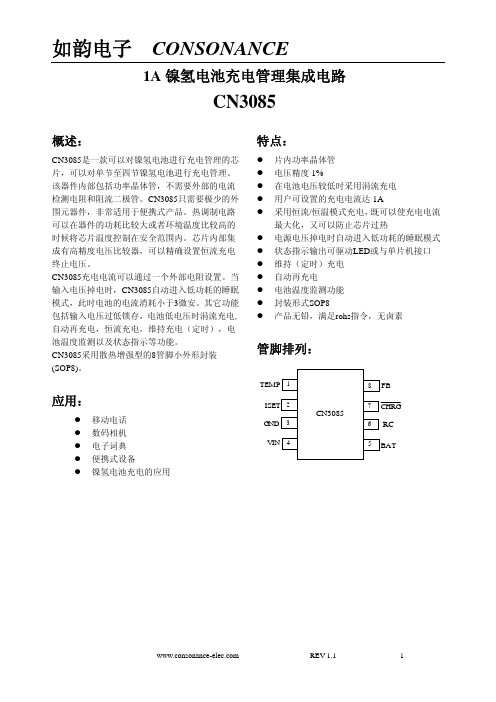
睡眠模式
CN3085内部有睡眠状态比较器,当输入电压VIN小于电池端电压+10mv时,充电器处于睡眠模式;只有 当输入电压VIN上升到电池端电压60mv以上时,充电器才离开睡眠模式,进入正常工作状态。
涓流充电状态
如果FB管脚电压低于0.84V,即电池电压低于电池端最高电压的69.4%,则CN3085处于涓流充电状态,充 电器以恒流充电电流的28.8%对电池进行充电。
3
1
TEMP
2
ISET
5
BAT
6
RC
其中, T(s)为定时时间,单位为“秒” R5单位为“欧姆”,应在20k至1M欧姆,否则定时不准确 C1单位为“法拉”,应大于1nF,否则定时不准确 7 漏极开路输出的充电状态指示端。 当CN3085处于涓充电状态, 恒流充电状 管脚被内部开关拉到低电平,表示充电正在进 态和维持充电状态时, 行;否则 管脚处于高阻态。 电池电压反馈输入端。电池电压通过此管脚反馈到CN3085,CN3085根据 FB管脚的电压决定充电状态。 FB管脚电压与电池端电压的对应关系为: VBAT=VFB×(1+R3/R4)
恒流充电状态
当FB管脚电压在0.84V和1.133V之间时, 即电池电压在电池端最高电压的69.4%和93.2%之间, , 则CN3085 处于恒流充电状态。充电电流公式为: ICH = 1216V / RISET 其中,ICH 表示充电电流,单位为安培 RISET 表示ISET管脚到地的电阻,单位为欧姆 例如,如果需要1安培的充电电流,则: RISET = 1216V/1A = 1.22kΩ 为了保证良好的稳定性和温度特性,RISET建议使用精度为1%的金属膜电阻。
REV 1.1 5
的28.8%;当FB管脚电压在0.84V和1.133V之间时,即电池电压在电池端最高电压的69.4%和93.2%之间, 充电器采用恒流模式对电池充电,充电电流由ISET管脚和GND之间的电阻确定;当FB管脚电压大于 1.133V时,即电池电压大于电池端最高电压的93.2%时,CN3085处于维持充电状态,维持充电电流为恒 流充电电流的28.8%,如果FB管脚电压达到1.216V,即电池电压接近电池端最高电压时,电池电压不再上 升,充电电流逐渐减小。在维持充电阶段,内部定时器启动,维持充电时间由第6管脚的电阻和电容决定 (图1中的R5和C1), 当定时结束时, 整个充电过程结束。 在充电结束状态, 当FB管脚电压下降到1.053V时, 即电池电压下降到电池端最高电压的86.6%时,CN3085进入再充电状态,开始新的充电周期。 当输入电压掉电或者输入电压低于电池电压时,充电器进入低功耗的睡眠模式,电池端消耗的电流 小于3uA,从而增加了待机时间。上述充电过程如图3所示:
六级能效充电器及适配器芯片TM0726_V1.0
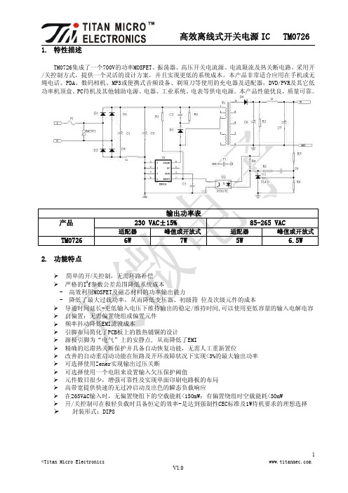
1.特性描述TM0726集成了一个700V的功率MOSFET、振荡器、高压开关电流源、电流限流及热关断电路。
采用开/关控制方式,提供一个灵活的设计方案,并且实现更低的系统成本。
本产品非常适合应用在手机或无绳电话、PDA、数码相机、MP3或便携式音频设备、剃须刀等使用的充电器及适配器,DVD/PVR及其它低功率机顶盒、PC待机及其他辅助电源、电器、工业系统、电表等供电电源。
本产品性能优良,质量可靠。
输出功率表产品230VAC±15%85-265VAC适配器峰值或开放式适配器峰值或开放式TM07266W7W5W 6.5W2.功能特点简单的开/关控制,无需环路补偿严格的I2f参数公差范围降低系统成本-高效利用MOSFET及磁芯材料的功率输出能力-降低了最大过载功率,从而降低变压器、初级箝位及次级元件的成本导通时间延长-更低输入电压下维持输出的稳定/维持时间,可以使用更低容量的输入电解电容 自偏置:无需偏置绕组或偏置元件频率抖动降低EMI滤波成本引脚布局简化了PCB板上的散热铺铜的设计源极引脚为“电气”上的安静点,从而降低了EMI精确的迟滞热关断保护并具备自动恢复功能,无需人工重新置位改善的自动重启动功能在短路及开环故障状况下实现<3%的最大输出功率可选择使用Zener实现输出过压关断可选择使用一个电阻来设置输入欠压保护阈值元件数目很少,增强可靠性及实现单面印刷电路板的布局高带宽提供快速的无过冲启动及出色的瞬态负载响应在265VAC输入时,无偏置绕组下的空载能耗<150mW;有偏置绕组时空载能耗<50mW开/关控制可在极轻负载时具备恒定的效率-是达到强制性CEC标准及1W待机要求的理想选择 封装形式:DIP83.内部结构框图SOURES管脚排列45362718DNCBP/MEN/UVSSSSTop View4.管脚功能引脚名称引脚序号I/O功能说明EN/UV1I具备两项功能:输入使能信号和输入线电压欠压检测。
RTL8305NB-CG_Datasheet_1.0_for Zycoo
RTL8305NB-CGSINGLE-CHIP 5-PORT 10/100M ETHERNETSWITCH CONTROLLERDATASHEET(CONFIDENTIAL: Development Partners Only)Rev. 1.016 October 2012Track ID: JATR-3375-16Realtek Semiconductor Corp.No. 2, Innovation Road II, Hsinchu Science Park, Hsinchu 300, TaiwanTel.: +886-3-578-0211. Fax: +886-3-577-6047Single-Chip 5-Port 10/100Mbps Ethernet Switch Controller ii Track ID: JATR-3375-16 Rev. 1.0COPYRIGHT©2012 Realtek Semiconductor Corp. All rights reserved. No part of this document may be reproduced, transmitted, transcribed, stored in a retrieval system, or translated into any language in any form or by any means without the written permission of Realtek Semiconductor Corp.DISCLAIMERRealtek provides this document ‘as is’, without warranty of any kind. Realtek may make improvements and/or changes in this document or in the product described in this document at any time. This document could include technical inaccuracies or typographical errors.TRADEMARKSRealtek is a trademark of Realtek Semiconductor Corporation. Other names mentioned in this document are trademarks/registered trademarks of their respective owners.USING THIS DOCUMENTThis document is intended for the software engineer’s reference and provides detailed programming information.Though every effort has been made to ensure that this document is current and accurate, more information may have become available subsequent to the production of this guide.REVISION HISTORYRevision Release Date Summary 1.0 2012/10/16 First release.Table of Contents1.GENERAL DESCRIPTION (1)2.FEATURES (2)3.SYSTEM APPLICATIONS (3)4.BLOCK DIAGRAM (4)5.PIN ASSIGNMENTS (5)5.1.P IN A SSIGNMENTS D IAGRAM (5)5.2.P ACKAGE I DENTIFICATION (5)5.3.P IN A SSIGNMENTS T ABLE (6)6.PIN DESCRIPTIONS (7)6.1.P IN A SSIGNMENT C ODES (7)6.2.M EDIA C ONNECTION P INS (7)6.3.M ISCELLANEOUS P INS (8)6.4.P ORT LED P INS (8)6.5.S TRAPPING P INS (9)6.6.R EGULATOR P INS (9)6.7.P OWER AND GND P INS (9)7.BASIC FUNCTION DESCRIPTIONS (10)7.1.S WITCH C ORE F UNCTION O VERVIEW (10)7.1.1.Flow Control (10)7.1.1.1IEEE 802.3x Full Duplex Flow Control (10)7.1.1.2Half Duplex Back Pressure (10)7.1.2.Address Search, Learning, and Aging (11)7.1.3.Half Duplex Operation (11)7.1.4.InterFrame Gap (11)7.1.5.Illegal Frame (11)7.2.P HYSICAL L AYER F UNCTIONAL O VERVIEW (12)7.2.1.Auto-Negotiation (12)7.2.2.10Base-T Transmit Function (12)7.2.3.10Base-T Receive Function (12)7.2.4.Link Monitor (12)7.2.5.100Base-TX Transmit Function (12)7.2.6.100Base-TX Receive Function (12)7.2.7.Power-Down Mode (13)7.2.8.Crossover Detection and Auto Correction (13)7.2.9.Polarity Detection and Correction (13)7.3.G ENERAL F UNCTION O VERVIEW (14)7.3.1.Power-On Sequence (14)7.3.2.Setup and Configuration (15)7.3.3.Serial EEPROM Example (16)7.3.3.1EEPROM Device Operation (16)7.3.3.2EEPROM Size Selection (18)7.3.4.SMI (18)7.3.5.Head-Of-Line Blocking (18)7.3.6.Filtering/Forwarding Reserved Control Frame (19)7.3.7.Loop Detection (19)7.3.8.Reg.0.14 PHY Digital Loopback Return to Internal (21)7.3.9.LDO for 1.0V Power Generation (22)7.3.10.Crystal/Oscillator (22)Single-Chip 5-Port 10/100Mbps Ethernet Switch Controller iii Track ID: JATR-3375-16 Rev. 1.08.ADVANCED FUNCTION DESCRIPTIONS (23)8.1.VLAN F UNCTION (23)8.1.1.VLAN Description (23)8.1.2.Port-Based VLAN (24)8.1.3.IEEE 802.1Q Tagged-VID Based VLAN (24)8.1.4.Insert/Remove/Replace Tag (24)8.1.5.Ingress and Egress Rules (25)8.2.IEEE802.1P R EMARKING F UNCTION (25)8.3.Q O S F UNCTION (26)8.3.1.Bandwidth Control (26)8.3.1.1Output (TX) Bandwidth Control (26)8.3.1.2Input (RX) Bandwidth Control (27)8.3.2.Priority Assignment (27)8.3.2.1Queue Number Selection (27)8.3.2.2Port-Based Priority Assignment (27)8.3.2.3IEEE 802.1p/Q-Based Priority Assignment (28)8.3.2.4DSCP-Based Priority Assignment (28)8.3.2.5IP Address-Based Priority (28)8.3.2.6Reassigned Priority (28)8.3.2.7RLDP-Based Priority (28)8.3.2.8Packet Priority Selection (29)8.4.L OOKUP T ABLE F UNCTION (30)8.4.1.Function Description (30)8.4.2.Address Search, Learning, and Aging (30)8.4.3.Lookup Table Definition (31)8.5.S TORM F ILTER F UNCTION (32)8.6.I NPUT AND O UTPUT D ROP F UNCTION (32)8.7.LED F UNCTION (33)8.8.E NERGY-E FFICIENT E THERNET (EEE) (34)8.9.C ABLE D IAGNOSIS (34)9.CHARACTERISTICS (35)9.1.E LECTRICAL C HARACTERISTICS/M AXIMUM R ATINGS (35)9.2.O PERATING R ANGE (35)9.3.DC C HARACTERISTICS (35)9.4.T HERMAL C HARACTERISTICS (36)9.4.1.Simulation Conditions (36)9.4.2.Thermal Characteristics Results (36)9.5.D IGITAL T IMING C HARACTERISTICS (37)9.5.1.LED Timing (37)9.5.2.Reception/Transmission Data Timing of SMI Interface (37)9.5.3.EEPROM Auto-Load Timing (38)10.MECHANICAL DIMENSIONS (39)10.1.M ECHANICAL D IMENSIONS N OTES (40)11.ORDERING INFORMATION (41)Single-Chip 5-Port 10/100Mbps Ethernet Switch Controller iv Track ID: JATR-3375-16 Rev. 1.0Single-Chip 5-Port 10/100Mbps Ethernet Switch Controller v Track ID: JATR-3375-16 Rev. 1.0List of TablesT ABLE 1.P IN A SSIGNMENTS T ABLE (6)T ABLE 2.M EDIA C ONNECTION P INS (7)T ABLE 3.M ISCELLANEOUS P INS (8)T ABLE 4.P ORT LED P INS (8)T ABLE 5.S TRAPPING P INS (9)T ABLE 6.R EGULATOR P INS (9)T ABLE 7.P OWER AND GND P INS (9)T ABLE 8.B ASIC SMI R EAD/W RITE C YCLES (18)T ABLE 9.E XTENDED SMI M ANAGEMENT F RAME F ORMAT (18)T ABLE 10.R ESERVED E THERNET M ULTICAST A DDRESSES (19)T ABLE 11.L OOP F RAME F ORMAT (20)T ABLE 12.C RYSTAL AND O SCILLATOR R EQUIREMENTS (22)T ABLE 13.VLAN T ABLE (23)T ABLE 14.VLAN E NTRY (23)T ABLE 15.L2T ABLE 4-W AY H ASH I NDEX M ETHOD (31)T ABLE 16.E LECTRICAL C HARACTERISTICS/M AXIMUM R ATINGS (35)T ABLE 17.O PERATING R ANGE (35)T ABLE 18.DC C HARACTERISTICS (35)T ABLE 19.PCB D ESCRIPTIONS (36)T ABLE 20.C ONDITION D ESCRIPTIONS (36)T ABLE 21.T HERMAL C HARACTERISTICS R ESULTS (36)T ABLE 22.LED T IMING (37)T ABLE 23.SMI T IMING (37)T ABLE 24.EEPROM A UTO-L OAD T IMING C HARACTERISTICS (38)T ABLE 25.O RDERING I NFORMATION (41)Single-Chip 5-Port 10/100Mbps Ethernet Switch Controller vi Track ID: JATR-3375-16 Rev. 1.0List of FiguresF IGURE 1.B LOCK D IAGRAM (4)F IGURE 2.P IN A SSIGNMENTS (5)F IGURE 3.C OLLISION-B ASED B ACKPRESSURE S IGNAL T IMING (10)F IGURE 4.P OWER-O N S EQUENCE (14)F IGURE 5.R ESET (15)F IGURE 6.S TART AND S TOP D EFINITION (17)F IGURE 7.O UTPUT A CKNOWLEDGE (17)F IGURE 8.R ANDOM R EAD (17)F IGURE 9.S EQUENTIAL R EAD (17)F IGURE 10.L OOP E XAMPLE (19)F IGURE 11.LED AND B UZZER C ONTROL S IGNAL FOR L OOP D ETECTION (20)F IGURE 12.L OOP E XAMPLE 2 (21)F IGURE 13.R EG.0.14L OOPBACK (21)F IGURE 14.P ACKET-S CHEDULING D IAGRAM (26)F IGURE 15.RTL8305NB P RIORITY A SSIGNMENT D IAGRAM (27)F IGURE 16.B ROADCAST I NPUT D ROP VS.O UTPUT D ROP (32)F IGURE 17.M ULTICAST I NPUT D ROP VS.O UTPUT D ROP (32)F IGURE 18.F LOATING AND P ULL-H IGH OF LED P INS FOR LED (33)F IGURE 19.R ECEPTION D ATA T IMING OF SMI I NTERFACE (37)F IGURE 20.T RANSMISSION D ATA T IMING OF SMI I NTERFACE (37)F IGURE 21.EEPROM A UTO-L OAD T IMING (38)Single-Chip 5-Port 10/100Mbps Ethernet Switch Controller 1Track ID: JATR-3375-16 Rev. 1.0 1.General DescriptionThe RTL8305NB is a 5-port 10/100M Ethernet switch controller that integrates memory, five MACs, and five physical layer transceivers for 10Base-T and 100Base-TX operation into a single chip.In order to accomplish diagnostics in complex network systems, the RTL8305NB provides a loopback feature in each port.The RTL8305NB supports several advanced QoS functions with four-level priority queues to improve multimedia or real-time networking applications, including:•Multi-priority assignment•Differential queue weight•Port-based rate limitation•Queue-based rate limitationThe RTL8305NB supports 16 VLAN groups. These can be configured as port-based VLANs and/or 802.1Q tag-based VLANs. The RTL8305NB also supports VLAN learning, with four Independent VLAN Learning (IVL) filtering databases.The RTL8305NB contains a 2K-entry address lookup table. A 4-way associative hash algorithm avoids hash collisions and maintains forwarding performance.Maximum packet length can be 2048 bytes. Three types of independent storm filter are provided to filter packet storms, and an intelligent switch engine prevents Head-of-Line blocking problems.The RTL8305NB supports Energy-Efficient Ethernet mode (EEE; defined in IEEE 802.3az) to minimize system power consumption. Energy-Efficient Ethernet (EEE) supports Low Power Idle Mode. When Low Power Idle Mode is enabled, systems on both sides of the link can disable portions of the functionality and save power during periods of low link utilization.To simplify the peripheral power circuit, the RTL8305NB integrates one LDO regulator to generate 1.0V from a 3.3V input power, and needs only one external diode.Single-Chip 5-Port 10/100Mbps Ethernet Switch Controller2Track ID: JATR-3375-16 Rev. 1.02. FeaturesBasic Switching Functions5-port switch controller with memory andtransceiver for 10Base-T and 100Base-TX Non-blocking wire-speed reception andtransmission and non-head-of-line-blocking forwardingComplies with IEEE 802.3/802.3u auto-negotiation Built-in high efficiency SRAM for packetbuffer, with 2K-entry lookup table and two 4-way associative hash algorithms 2048 byte maximum packet length Flow control fully supportedHalf duplex: Back pressure flow control Full duplex: IEEE 802.3x flow controlService QualitySupports high performance QoS function oneach portSupports 4-level priority queues Weighted round robin service Supports strict priorityInput/Output port bandwidth control Queue-based bandwidth control 1Q-based, Port-based, DSCP-based, IPaddress-based, and other types of priority assignmentsSupports IEEE 802.1p Traffic Remarking Security and ManagementSupports reserved control frame filtering Supports advanced storm filteringOptional EEPROM interface forconfiguration VLAN FunctionsSupports up to 16 VLAN groups Flexible 802.1Q port/tag-based VLAN Supports four IVLsLeaky VLAN forunicast/multicast/broadcast/ARP packets Power Saving FunctionsSupports Energy-Efficient Ethernet (EEE)function (IEEE 802.3az) Link Down Power Saving Mode Diagnostic FunctionsSupports hardware loop detection functionwith LEDs and buzzer to indicate the existence of a loop Supports cable diagnosis (RTCT function) Flexible LED indicatorsRTCT status indication Loop status indication LEDs blink upon reset for LEDdiagnosticsOther FeaturesOptional MDI/MDIX auto crossover forplug-and-play Physical layer port Polarity Detection andCorrection function Robust baseline wander correction forimproved 100Base-TX performanceSingle-Chip 5-Port 10/100Mbps Ethernet Switch Controller 3Track ID: JATR-3375-16 Rev. 1.0 25MHz crystal or 3.3V OSC inputSingle 3.3V power input can be transformedby integrating an LDO regulator to generate1.0V from 3.3V via a low-cost externaldiodeLow power, 1.0/3.3V, 55nm CMOStechnology48-pin QFN ‘Green’ package3.System Applications5-port switch (10Base-T & 100Base-TX)Single-Chip 5-Port 10/100Mbps Ethernet Switch Controller 4Track ID: JATR-3375-16 Rev. 1.0 4.Block DiagramFigure 1. Block DiagramSingle-Chip 5-Port 10/100Mbps Ethernet Switch Controller 5Track ID: JATR-3375-16 Rev. 1.0 5.Pin Assignments5.1.Pin Assignments DiagramFigure 2. Pin Assignments5.2.Package IdentificationGreen package is indicated by a ‘G’ in the location marked ‘TXXXX’ in Figure 2.Single-Chip 5-Port 10/100Mbps Ethernet Switch Controller 6 Track ID: JATR-3375-16 Rev. 1.05.3. Pin Assignments Table‘Type’ codes used in the following table: A=Analog, D=Digital, I=Input, O=Output, I/O=Input/Output,I PU =Input Pin with Pull-Up Resistor, I PD =Input Pin with Pull-Down Resistor. Table 1. Pin Assignments TableName Pin No. Type A VDDL 1 AP RXIP1 2 AI/O RXIN1 3 AI/O TXON1 4 AI/O TXOP1 5 AI/O A VDDH 6 AP DVDDL 7 P A VDDH 8 P TXOP2 9 AI/O TXON2 10 AI/O RXIN2 11 AI/O RXIP2 12 AI/O A VDDL 13 AP RXIP3 14 AI/O RXIN3 15 AI/O TXON3 16 AI/O TXOP3 17 AI/O A VDDH 18 AP TXOP4 19 AI/O TXON4 20 AI/O RXIN4 21 AI/O RXIP4 22 AI/O A VDDL 23 AP DVDDL 24 P SCL/MDC 25 I/O PUName Pin No. TypeSDA/MDIO 26 I/O PURESETB 27 I PULDIND/DIS_LD 28 I/O PUP0LED/DIS_EEE 29 I/O PDP1LED 30 I/O PDDVDDH 31 P P2LED/DIS_RST_BLNK 32 I/O PDP3LED 33 I/O PDP4LED 34 I/O PDDVDDL 35 P V10OUT 36 AO V33IN 37 AP A VDDHPLL 38 APXO 39 AO XI 40 AI A VDDLPLL 41 AP IBREF 42 AO A VDDL 43 AP RXIP0 44 AI/O RXIN0 45 AI/O TXON0 46 AI/O TXOP0 47 AI/O A VDDH 48 AP E-PAD E-PAD GSingle-Chip 5-Port 10/100Mbps Ethernet Switch Controller 7Track ID: JATR-3375-16 Rev. 1.0 6.Pin Descriptions6.1.Pin Assignment CodesI: Input Pin AI:Analog Input PinO: Output Pin AO:Analog Output PinI/O: Bi-Directional Input/Output Pin AI/O:Analog Bi-Directional Input/Output PinP: Digital Power Pin AP:Analog Power PinG: Digital Ground Pin AG:Analog Ground PinI PU: Input Pin With Pull-Up Resistor;(Typical Value is about 75KΩ)O PU:Output Pin With Pull-Up Resistor;(Typical Value is about 75KΩ)I PD: Input Pin With Pull-Down Resistor;(Typical Value is about 75KΩ)O PD:Output Pin With Pull-Down Resistor;(Typical Value is about 75KΩ) I/O PU: I PU and O PU I/O PD:I PD and O PD6.2.Media Connection PinsTable 2. Media Connection PinsPin Name Pin No. Type Drive (mA)DescriptionRXIP4/RXIN4RXIP3/RXIN3RXIP2/RXIN2RXIP1/RXIN1RXIP0/RXIN022, 2114, 1512, 112, 344, 45AI/O - Differential Receive Data Input.Port0~4 support 10Base-T, 100Base-TX.TXOP4/TXON4TXOP3/TXON3TXOP2/TXON2TXOP1/TXON1TXOP0/TXON019, 2017, 169, 105, 447, 46AI/O - Differential Transmit Data Output.Port0~4 support 10Base-T, 100Base-TX.Single-Chip 5-Port 10/100Mbps Ethernet Switch Controller 8Track ID: JATR-3375-16 Rev. 1.0 6.3.Miscellaneous PinsAs the output of the RTL8305NB is 3.3V, the serial EEPROM and external device must be 3.3V compatible.Table 3. Miscellaneous PinsPin Name Pin No. Type Drive (mA)DescriptionLDIND/DIS_LD 28 I/O PU10 Loop Indication Used by LED and Buzzer.SCL/MDC 25I/O PU 4 I2C Interface Clock for EEPROM Auto Load when Power On.After power on, this pin is MDC/MDIO Interface Clock for accessregisters.SDA/MDIO 26I/O PU 4 I2C Interface Data Input/Output for EEPROM Auto Load whenPower On.After power on, this pin is MDC/MDIO Interface DataInput/Output for access registers.RESETB 27I PU- System Pin Reset Input.XI 40 AI - 25MHz Crystal Clock Input.The clock tolerance is ±50ppm.XO 39 AO - 25MHz Crystal Clock Output Pin.When the pin of XI is using an oscillator this pin should befloating.IBREF 42 AO - Reference Resistor for PHY Bandgap.A 2.49KΩ (1%) resistor should be connected between IBREF andGND.6.4.Port LED PinsAll LED statuses are represented as active-low or high depending on input strapping.Those pins that are dual-function pins are output for LED, or input for strapping. Below are LED descriptions only.Table 4. Port LED PinsPin Name Pin No. Type Drive (mA)DescriptionP0LED/DIS_EEE 29 I/O PD10 LED for Port0 Status Indication.P1LED 30I/O PD10 LED for Port1 Status Indication.P2LED/DIS_RST_BLNK32 I/O PD10 LED for Port2 Status Indication.P3LED 33I/O PD10 LED for Port3 Status Indication.P4LED 34I/O PD10 LED for Port4 Status Indication.Single-Chip 5-Port 10/100Mbps Ethernet Switch Controller 9Track ID: JATR-3375-16 Rev. 1.0 6.5.Strapping PinsPins that are dual function pins are outputs for LED or inputs for strapping. Below are strapping descriptions only.Table 5. Strapping PinsPin Name Pin No.Type Default DescriptionDIS_LD/LDIND 28 I/O PU- Disable Loop Detection Function.0: Enable1: Disable (default)DIS_EEE/P0LED 29 I/O PD- Disable EEE Function.0: Enable EEE function (default)1: Disable EEE functionDIS_RST_BLNK/P2LED32 I/O PD- Disable LED Power on Blinking.0: Enable (default)1: Disable6.6.Regulator PinsTable 6. Regulator PinsPin Name Pin No.Type Drive (mA) DescriptionV10OUT 36 AO - Switch Regulator 1.0V Output.V33IN 37 AP - Switch Regulator 3.3V Input.6.7.Power and GND PinsTable 7. Power and GND PinsPin Name Pin No. Type DescriptionA VDDH 6, 8, 18, 48 AP Analog Power 3.3V.A VDDL 1, 13, 23, 43 AP Analog Power 1.0V.A VDDHPLL 38 AP Power 3.3V for PLL.A VDDLPLL 41 AP Power 1.0V for PLL.DVDDH 31 P Digital Power 3.3V for IO Pin.DVDDL 7, 24, 35 P Digital Power 1.0V for Core V oltage.GND E-PADGGroundforWholeChip.Single-Chip 5-Port 10/100Mbps Ethernet Switch Controller 10 Track ID: JATR-3375-16 Rev. 1.07. Basic Function Descriptions7.1. Switch Core Function Overview 7.1.1. Flow ControlThe RTL8305NB supports IEEE 802.3x full duplex flow control, force mode full duplex flow control, and optional half duplex backpressure.7.1.1.1IEEE 802.3x Full Duplex Flow Control For UTP with auto-negotiation ability, the pause ability of full duplex flow control is enabled by internalregisters via SMI on a per-port basis after reset. IEEE 802.3x flow control’s ability is auto-negotiated between the remote device and the RTL8305NB. If the auto-negotiation result of the IEEE 802.3x pause ability is ‘Enabled’, the full duplex 802.3x flow control function is enabled. Otherwise, full duplex IEEE 802.3x flow control function is disabled.7.1.1.2Half Duplex Back PressureThere are two mechanisms for half duplex backpressure; collision-based or carrier-based.Collision-Based Backpressure (Jam Mode) If the buffer is ready to overflow, this mechanism will force a collision. When the link partner detects thiscollision, the transmission is rescheduled.The Reschedule procedure is: •The RTL8305NB will drive TXEN to high and send the preamble; SFD and a 4-byte Jam signal(pattern is 0xAA). The RTL8305NB will then drive TXEN to low •When the link partner receives the Jam signal, it will feedback a 4-byte signal (pattern is CRC^0x01),it will then drive RXDV to low •The link partner waits for a random back-off time then re-sends the packet. The timing is shown inFigure 3Figure 3. Collision-Based Backpressure Signal TimingCarrier-Based Backpressure (Defer Mode)If the buffer is about to overflow, this mechanism will send an 0xAA pattern to defer the other station’s transmission. The RTL8305NB will continuously send the defer signal until the buffer overflow is resolved.7.1.2.Address Search, Learning, and AgingWhen a packet is received, the RTL8305NB will use the destination MAC address and FID to index the 2048-entry lookup table. If the indexed entry is valid, the received packet will be forwarded to the corresponding destination port. Otherwise, the RTL8305NB will broadcast the packet. This is the ‘Address Search’.The RTL8305NB then combines the source MAC address and the FID to index the 2048-entry lookup table. If the entry is not in the table it will record the source MAC address and add switching information. If this is an occupied entry, it will update the entry with new information when LRU is enabled. This is called ‘Learning’.Address aging is used to keep the contents of the address table correct in a dynamic network topology. The lookup engine will update the time stamp information of an entry whenever the corresponding source MAC address appears. An entry will be invalid (aged-out) if its time stamp information is not refreshed by the address learning process during the aging time period. The aging time of the RTL8305NB is between 200 and 400 seconds.7.1.3.Half Duplex OperationIn half duplex mode, the CSMA/CD media access method is the means by which two or more stations share a common transmission medium. To transmit, a station waits (defers) for a quiet period on the medium (that is, no other station is transmitting) and then sends the intended message in bit-serial form. If the message collides with that of another station, then each transmitting station intentionally transmits for an additional predefined period to ensure propagation of the collision throughout the system. The station remains silent for a random amount of time (backoff) before attempting to transmit again.When a transmission attempt has terminated due to a collision, it is retried until it is successful. A controlled randomization process called ‘truncated binary exponential backoff’ determines the scheduling of the retransmissions. At the end of enforcing a collision (jamming), the switch delays before attempting to retransmit the frame. The delay is an integer multiple of slot time (512 bit times). The number of slot times to delay before the n th retransmission attempt is chosen as a uniformly distributed random integer ‘r’ in the range:0 ≤ r < 2kwhere:k = min (n, backoffLimit). IEEE 802.3 defines the backoffLimit as 10.7.1.4.InterFrame GapThe InterFrame Gap is 9.6µs for 10Mbps Ethernet and 960ns for 100Mbps Fast Ethernet.7.1.5.Illegal FrameIllegal frames such as CRC error packets, runt packets (length < 64 bytes), and oversize packets (length > maximum length), will be discarded.Single-Chip 5-Port 10/100Mbps Ethernet Switch Controller 11Track ID: JATR-3375-16 Rev. 1.0Single-Chip 5-Port 10/100Mbps Ethernet Switch Controller 12Track ID: JATR-3375-16 Rev. 1.0 7.2.Physical Layer Functional Overview7.2.1.Auto-NegotiationThe RTL8305NB obtains the states of duplex, speed, and flow control ability for each port through the auto-negotiation mechanism defined in the IEEE 802.3 specifications. During auto-negotiation, each port advertises its ability to its link partner and compares its ability with advertisements received from its link partner. By default, the RTL8305NB advertises full capabilities (100Full, 100Half, 10Full, 10Half) together with flow control ability. The RTL8305NB also advertises the Energy Efficient Ethernet (EEE) capability to the link partner.7.2.2.10Base-T Transmit FunctionThe output 10Base-T waveform is Manchester-encoded before it is driven onto the network media. The internal filter shapes the driven signals to reduce EMI emissions, eliminating the need for an external filter.7.2.3.10Base-T Receive FunctionThe Manchester decoder converts the incoming serial stream to NRZ data when the squelch circuit detects the signal level is above squelch level.7.2.4.Link MonitorThe 10Base-T link pulse detection circuit continually monitors the RXIP/RXIN pins for the presence of valid link pulses. Auto-polarity is implemented to correct the detected reverse polarity of RXIP/RXIN signal pairs.7.2.5.100Base-TX Transmit FunctionThe 100Base-TX transmit function performs parallel to serial conversion, 4B/5B coding, scrambling, NRZ/NRZI conversion, and MLT-3 encoding. The 5-bit serial data stream after 4B/5B coding is then scrambled as defined by the TP-PMD Stream Cipher function to flatten the power spectrum energy such that EMI effects are significantly reduced.The scrambled seed is based on PHY addresses and is unique for each port. After scrambling, the bit stream is driven into the network media in the form of MLT-3 signaling. The MLT-3 multi-level signaling technology moves the power spectrum energy from high frequency to low frequency, which further reduces EMI emissions.7.2.6.100Base-TX Receive FunctionThe receive path includes a receiver composed of an adaptive equalizer and DC restoration circuits (to compensate for an incoming distorted MLT-3 signal), an MLT-3 to NRZI and NRZI to NRZ converter to convert analog signals to digital bit-stream, and a PLL circuit to clock data bits with minimum bit error rate. A De-scrambler, 5B/4B decoder, and serial-to-parallel conversion circuits are followed by the PLL circuit. Finally, the converted parallel data is fed into the MAC.7.2.7.Power-Down ModeThe RTL8305NB implements power-down mode on a per-port basis. Setting MII Reg.0.11 forces the corresponding port of the RTL8305NB to enter power-down mode. This disables all transmit/receive functions, except SMI (Serial Management Interface: MDC/MDIO, also known as MII Management Interface).7.2.8.Crossover Detection and Auto CorrectionDuring the link setup phase, the RTL8305NB checks whether it receives active signals on every port in order to determine if a connection can be established. In cases where the receiver data pin pair is connected to the transmitter data pin pair of the peer device and vice versa, the RTL8305NB automatically changes its configuration and swaps receiver/transmitter data pins as required. If a port is connected to a PC or NIC with MDI-X interface with a crossover cable, the RTL8305NB will reconfigure the port to ensure proper connection. This replaces the DIP switch commonly used for reconfiguring a port on a hub or switch.Note: IEEE 802.3 compliant forced mode 100M ports with Autoxover have link problems with NWay (Auto-Negotiation) ports. It is recommended to not use Autoxover for forced 100M.7.2.9.Polarity Detection and CorrectionFor better noise immunity and lower interference to ambient devices, the Ethernet electrical signal on a twisted-pair cable is transmitted in differential form. That is, the signal is transmitted on two wires in each direction with inverse polarities (+/-). If wiring on the connector is faulty, or a faulty transformer is used, the two inputs to a transceiver may carry signals with opposite but incorrect polarities. As a direct consequence, the transceiver will not work properly.When the RTL8305NB operates in 10Base-T mode, it automatically reverses the polarity of its two receiver input pins if it detects that the polarities of the incoming signals on the pins is incorrect. However, this feature is unnecessary when the RTL8305NB is operating in 100Base-TX mode.Single-Chip 5-Port 10/100Mbps Ethernet Switch Controller 13Track ID: JATR-3375-16 Rev. 1.0Single-Chip 5-Port 10/100Mbps Ethernet Switch Controller 14 Track ID: JATR-3375-16 Rev. 1.0 7.3. General Function Overview7.3.1. Power-On SequenceTwo power voltage types are required for RTL8305NB normal operation, 3.3V and 1.0V. The 1.0V is converted from 3.3V via the LDO of the RTL8305NB.• Ta is the moment when 3.3V power is higher than 2.6V (±5%). 3.3V power never falls lower than2.6V (±5%) after Ta• Tb is the moment when 1.0V power is higher than 0.71V (±10%). 1.0V power never falls lower than 0.71V (±10%) after Tb • Tc is the moment when both 3.3V and 1.0V power are stable (the voltage is always in the legal operating range) • Td is the moment that the pin reset signal is de-asserted •Te is the moment that the RTL8305NB device is ready to be accessed by an external CPUFigure 4. Power-On SequenceThe requirements are:• The time of Ta should be between 1ms and 20ms• The sequence of Ta is always less than Tb for the LDO of the RTL8305NB. In principle, the sequence of Td and Ta/Tb/Tc is also not required. The sequence of Td > Tc + 10ms is recommended• The time from Te to the later of Ta/Tb/Td is the sum of the time of the EEPROM loading + 30ms. The EEPROM loading time varies according to the autoloaded data bytes in the serial EEPROM• Reset。
2019充电器适配器方案DEMO 简介
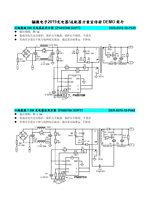
骊微电子2019充电器/适配器方案宣传册 DEMO 简介六级能效 5W 充电器应用方案(PN8570M SOP7) 输出规格:5V/1A 集成市电欠过压保护,保护点不振荡,保护后不锁死、不重启 有效区分雷击干扰与电网电压波动,通过雷击标准 A,不掉电DER-8570-18-P039六级能效 7.5W 充电器应用方案(PN8570H SOP7) 输出规格:5V/1.5A 集成市电欠过压保护,保护点不振荡,保护后不锁死、不重启 有效区分雷击干扰与电网电压波动,通过雷击标准 A,不掉电DER-8570-18-P042六级能效 6W 适配器应用方案(PN8366M SOP7) 输出规格:12V/0.5A 高压启动+多工作模式+专利谷底开通技术,满足 CoC V5 Tier 2 方案精简:节省启动电阻、Y 电容、输出共模DER-8366M-15-P051六级能效 10W 充电器应用方案(PN6370T SOP7)DER-6370T-18-P003 输入规格:85~420Vac 输出规格:5V/2A 高压启动+多工作模式+专利谷底开通技术+同步整流技术,满足 COC V5 Tier 2 集成市电欠过压保护,保护点不振荡,保护后不锁死、不重启 有效区分雷击干扰与电网电压波动,通过雷击标准 A,不掉电L NCE1 10uF/500VCE2 10uF/500VR5 R4 5.1M 5.1MC1 1nF/1kVR2 200K R18 20R CE3 470uF/6.3V R15 2K CE4 470uF/6.3VBD1 ABS210FR1 5R 2WF1 T3.15A/250VL1 1mH R1 NCT1R3 150Ω D1 A7 R5 2R D2 F7L2 3.3uH C2 10uF/ 50VR9 51kΩ100pF/ 50V C3R10 6.8kΩ C4 R1147pF/ 2.2R 50VR7 36K R8 1K17VDD GND2 OV/BO3 FB6 SW4 CS5 SWR121.6R PN6370TPN8306MSWVCCSWNC C6SW0.1uF/50V GNDSWGNDCY1 1nF/500V+5V GND六级能效 12W 充电器应用方案(PN8386F SOP8) 输出规格:5V/2.4A 高压启动+多工作模式 +同步整流技术,满足 COC V5 Tier 2DER-8386F-18-P044 PN8386F 独特 PFM 工作曲线,降低变压器体积,简化 EMC 设计六级能效 12W 适配器应用方案(PN8610 SOP7) 输出规格:12V/1A EMC 特性卓越:去 Y、去输入共模、去输出共模 方案精简:节省启动线路、VDD 供电二极管、FB 采样电路DER-8610-18-P045六级能效 15.5W 充电器应用方案(PN8386P DIP8) 输出规格:5V/3.1A 高压启动+多工作模式+同步整流技术,满足 COC V5 Tier 2 PN8386P 独特 PFM 工作曲线,降低变压器体积,简化 EMC 设计DER-8386P-17-P030六级能效 18W PD 快充应用方案(PN8161+PN8307H)DER-8161-18-P040 典型输出规格:12V1.5A、9V2A、5V3A 节省 10 颗以上外围:无启动电阻、无 CS 侦测网络,原副边均实现 SOP8 功率集成 满足 CoC V5 Tier 2: 30mW 待机功耗、平均效率裕量均大于 4 个点 EMC 性能卓越:抖频幅度随负载自适应,改善传导;DCM/QR 工作模式,改善辐射 3.3~12V 宽输出电压范围:PN8161/PN8307H 供电范围宽,无需额外 LDO 稳压 协议芯片任意搭:SSR 架构,方案易满足 PD3.0/Quick Charge 4+等快充规范六级能效 18W 适配器应用方案(PN8395 SOP8) 输出规格:12V/1.5A 高压启动+多工作模式,满足 COC V5 Tier 2 支持 DCM 和 CCM 模式恒流,减小变压器尺寸DER-8395-16-P017F1 LT5.0A/250V RV1 14D651N FR1 1Ω/2WBD1 ABS210LF1CE1 10uF/400V22uF/400VCE2 C1 1nFEE16WR1 470kΩT1 1R2 200Ω51Ω 1nF R10 C4R3D1200ΩM76 D310A/80VR4R510Ω 18kΩU12R8 2.0Ω PN8395CE4680uF CE5/16V 680uF7/16VD2 F1MR6 3kΩR7 3.9kΩR9 2.0ΩC2 27pFCE3 10uF/50VC3 100nFCSSWFBSWGND SW VCC SW5CY1 470pF12V1.5AR11 10kΩGND六级能效 24W 适配器应用方案(PN8395+PN8308L) 输出规格:12V/2A 高压启动+多工作模式+同步整流技术,满足 COC V5 Tier 2 方案精简:节省启动电阻、CS 采样电路、散热片、次级反馈网络DER-8395-16-P018LF1 T5.0A/250VRV1 10D561NFR1 1Ω/2WR4 10ΩD2 F1MBD1 ABS210CE2 LF1 33uF/400V 20mHC1 1nFR1 R1 1.5MΩ1.5MΩT1 1C5 R9 1nF/100V 51Ω 7+12VCE1 15uF/400VR5 22.6kΩ R82.0ΩR7 2.0ΩR6 3.9kΩC2 47pFCE3C310uF/50V 100nFR3 D1100Ω M7U1PN8395CSSWFBSWGND SWVCCSW3 26 5EE19WSWVCCSWNCSWGNDSWGNDU2PN8308LR10 10kC4 0.1uF/50VGNDCE4CE5680uF/16V 680uF/16VCY1 470pF六级能效 24W 适配器应用方案(PN8160T+PN8308M)DER-8308M-18-P025 输出规格:12V/2A 高压启动+多工作模式+同步整流技术,顺绕变压器即可满足 CoC V5 Tier 2 方案精简:节省启动电阻、CS 采样电路、散热片六级能效 27W 充电器应用方案(PN8235 SOP7) 输出规格:5V/5.4A 850V 高耐压启动管,高压脚与低压脚爬电距离大于 2.5mm,更高安全性 高压启动+多工作模式+同步整流技术,满足 CoC V5 Tier 2 PN8300 独有双供电技术,彻底解决异常工况下的 SR 供电问题DER-8235-16-P034六级能效 36W 适配器应用方案(PN8275+PN8308H) 输出规格:12V/3A 内置 850V 高压模块实现 X 放电功能(CB 证书编号:DK-76617-UL) HV 脚可实现精确市电异常保护:OVP、Brown in/out 高压启动+多工作模式+同步整流技术,满足 CoC V5 Tier 2DER-8308-18-P014六级能效 65W 适配器应用方案(AP8268 SOT23-6) 输出规格 19V/3.4A 高低压分频技术(65k/85k):减小变压器尺寸 谷底开通+混合工作模式提高全负载段转换效率 VDD 电压 8-40V,适合宽输出应用 DMG 监控市电及输出电压,精确输出 OVP 及输入电压 OCP 补偿(外部可调)DER-8268-17-P0315W/7.5W/10W 无线充方案(PN7724 ESOP8)DER-7724-18-P046 方案精简:集成驱动、4 颗功率管、高压 LDO 安全可靠:单芯片设计,防止直通,自适应死驱利于 FOD 侦测 ESOP8 封装:热阻小,散热好 集成无损自举电路:无需外置自举二极管,上管导通更充分,BS 电容仅需 10nF。
LN9T27PD+LN5S06B-65W 六级能效快充电源说明书
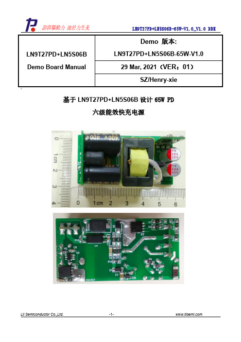
`基于LN9T27PD+LN5S06B 设计65W PD六级能效快充电源LN9T27PD+LN5S06B Demo Board ManualDemo 版本:LN9T27PD+LN5S06B-65W-V1.029Mar,2021(VER :01)SZ/Henry-xie主要特性:1、输入电压范围90VAC~265VAC2、输出特性:5V/3A,9V/3A,12V/3A,15V/3A,20V/3.25A3、输出总功率为65W4、符合“DOE&COC”6级能效标准5、通过EN55022ClassB的EMI测试标准6、通过EFT、urges4KV测试标准目录一DEMO参数信息 (3)二电源结构 (4)2.1原理图 (4)2.2材料清单 (5)2.3Demo板结构示意 (6)三、测试数据 (7)3.1输入特性 (7)3.1.1待机功耗 (7)3.1.2恒压效率..........................................................................................................................................7-103.1.3启动电压 (10)3.2输出特性 (11)3.2.1输出纹波 (11)3.2.2.1负载:5V3A (12)3.2.2.2负载:9V3A (11)3.2.2.3负载:12V3A (13)3.2.2.3负载:15V3A (13)3.2.2.4负载:20V3.25A (12)3.2.3输出同步整流管波形 (14)3.2.4MOS管漏端电压 (15)3.3可靠性测试 (15)3.3.1温度测试 (16)3.3.2关键点波形 (16)3.3.3高压测试 (17)3.4EMI测试 (17)3.4.1传导测试.........................................................................................................................................17-21一DEMO参数信息描述符号最小典型最大单位备注输入特性输入电压范围VIN90264Vac2相线输入频率范围FLINE4750/6063Hz待机功耗52mW230VAC输出特性1输出电压V OUT 4.95 5.1 5.25V输出电流I OUT03A输出特性2输出电压V OUT8.7899.27V输出电流I OUT03A输出特性3输出电压V OUT11.751212.36V输出电流I OUT03A输出特性4输出电压V OUT14.751515.36V输出电流I OUT03A输出特性5输出电压V OUT19.72020.2V输出电流I OUT0 3.25A性能描述平均效率1η89.17%V0=5V@230V AC 平均效率2η91.11%V0=9V@230V AC 平均效率3η91.98%V0=12V@230V AC 平均效率4η92.01%V0=15V@230V AC 平均效率5η92.22%V0=20V@230V AC 电压调整率±1%负载调整率±3%启动时间T ST_DELAY<3sEMI EN55022B保护特性短路保护输出关闭(打嗝模式),可自恢复过流保护输出关闭(监控模式),可自恢复环境特性工作温度040℃工作湿度20%90%R.H.储存温度-4060℃储存湿度0%95%R.H.二电源结构2.1原理图应用原理图2.2表1材料清单2.3Demo板结构示图2顶层布线元件图3底层布线元件三、测试数据3.1输入特性表4待机功耗数据3.1.2恒压效率3.1.2.1负载:5V3A备注:此效率数据为板端测试3.1.2.2负载:9V3A3.1.2.3负载:12V3A3.1.2.3负载:15V3A备注:此效率数据为板端测试4.1.2.4负载:20V3.25A备注:此效率数据为板端测试3.1.3启动电压表9启动电压数据图590VAC5V/3A启动波形3.2.2输出纹波3.2.2.1负载:5V3A带Tpye-c线1.5m,线端测试表11纹波数据90Vac,Full Load264Vac,Full Load 3.2.2.2负载:9V3A表12纹波数据90Vac,Full Load264Vac,Full Load3.2.2.3负载:12V3A表13纹波数据90Vac,Full Load264Vac,Full Load 3.2.2.4负载:15V3A表14纹波数据90Vac,Full Load264Vac,Full Load3.2.2.5负载:20V3.25A表14纹波数据90Vac,Full Load264Vac,Full Load3.2.3输出同步整流波形图14输出同步整流MOS管电压波形3.2.4MOS管漏端电压输入:265VAC;输出:20V3.25A。
Booster 430 630 30560, 30562快速充电器说明书

Manual de instruccionesDispositivo de carga rápidaBooster 430/63030560, 30562Imágenes similares, pueden variar según el modeloLea atentamente las instrucciones de funcionamiento e indicaciones de seguridad contenidas en este manual antes de usar por primera vez el dispositivo.Queda reservado el derecho a modificaciones técnicas.A través de un proceso de mejora continua, imágenes, pasos a seguir y datos técnicos pueden verse afectados y variar ligeramente.Las informaciones contenidas en este documento pueden ser en cualquier momento y sin previo avi-so modificadas. Ninguna parte de este documento puede ser, sin autorización previa y por escrito, co-piada o de otro modo reproducida. Quedan reservados todos los derechos.La empresa WilTec Wildanger Technik GmbH no asume ninguna responsabilidad sobre posibles erro-res contenidos en este manual de instrucciones o en el diagrama de conexión del dispositivo.A pesar de que la empresa WilTec Wildanger Technik GmbH ha realizado el mayor esfuerzo posible para asegurarse de que este manual de instrucciones sea completo, preciso y actual, no se descarta que pudieran existir errores.En el caso de que usted encontrara algún error o quisiera hacernos una sugerencia para ayudarnos a mejorar, estaremos encantados de escucharle.Envíenos un e-mail a:*******************o utilice nuestro formulario de contacto:https://www.wiltec.de/contacts/La versión actual de este manual de instrucciones disponible en varios idiomas la puede encontrar en nuestra tienda online:https://www.wiltec.de/docsearchNuestra dirección postal es:WilTec Wildanger Technik GmbHKönigsbenden 1252249 Eschweiler¿Desea hacer la recogida usted mismo? Nuestra dirección de recogida es:WilTec Wildanger Technik GmbHKönigsbenden 2852249 EschweilerPara acortar el tiempo de espera y garantizar una rápida atención in situ, le pedimos que se ponga previamente en contacto con nosotros o realice su pedido a través de la tienda online.E-Mail:*******************Tel: +49 2403 55592-0Fax: +49 2403 55592-15Para la devolución de su mercancía en caso de cambio, reparación u otros fines, utilice la siguiente dirección. ¡Atención! Para garantizar un proceso de reclamación o devolución libre de complicaciones, por favor, póngase en contacto con nuestro equipo de atención al cliente antes de realizar la devolu-ción.Departamento de devolucionesWilTec Wildanger Technik GmbHKönigsbenden 2852249 EschweilerE-mail: *******************Tel: +49 2403 55592-0Fax: (+49 2403 55592-15)IntroducciónMuchas gracias por haberse decidido a comprar este producto de calidad. Para minimizar el riesgo de lesiones, le rogamos que tome algunas medidas básicas de seguridad siempre que usted utilice este dispositivo. Por favor, lea detenidamente y al completo este manual de instrucciones y asegúrese de haberlo entendido.Guarde bien este manual de instrucciones.IndicacionesPonga el dispositivo cargador en “OFF” (apagado) antes de conectar el cable de conexión a la batería para evitar chispas peligrosas.Antes de quitar las pinzas de la batería, apague el dispositivo.Durante el proceso de carga pueden formarse gases explosivos, por ello evite el fuego, las chispas, etc.La pinza roja de la batería se conecta con el polo positivo y la pinza negra con el polo negati-vo. ¡NUNCA las intercambie!No utilice NUNCA el dispositivo cargador si los cables de carga o los bornes de la batería es-tuvieran dañados. Durante la carga, no lo golpee ni lo sacuda.No intente NUNCA cargar una batería congelada.Utilice los fusibles que se incluyen en el envío. NUNCA instale fusibles mayores.Limpie cuidadosamente la batería antes de la carga y compruebe su voltaje.Tenga en cuenta que la batería conectada debe tener mín. 50 Ah y máx. 750 Ah (Boos-ter 430) ó 800 Ah (Booster 630).Manejo seguro de las baterías•¡Utilice siempre gafas de seguridad y guantes de protección al manejar la batería! El contacto de la piel, los ojos o la ropa con el ácido de la batería debe ser evitado en todo caso, ya que el ácido es altamente corrosivo. Si el ácido de la batería entrara en contacto con los ojos, es-tos deben ser enjuagados inmediatamente con abundante agua, a continuación, póngase en contacto con un médico. Las salpicaduras de ácido en la piel deben ser eliminadas al momen-to con agua y jabón. Las salpicaduras de ácido en la ropa producen agujeros.•No coloque su cargador de baterías sobre materiales inflamables durante el proceso de car-ga. Durante su funcionamiento, el dispositivo se calienta. Coloque el cargador de manera que pueda ventilar adecuadamente. ¡Nunca cubra las ranuras de ventilación! El dispositivo de car-ga solo puede ser utilizado en espacios interiores. Proteja el dispositivo de humedad y humo.Si el dispositivo se mojara, existe el riesgo de sufrir una descarga eléctrica con peligro de muerte. Al cargar la batería, se liberan pequeñas cantidades de gas del ácido que esta contie-ne. Esto es normal. El gas de la batería se nota por la formación de burbujas. Tenga cuidado con las burbujas de gas que estallan, ya que causan salpicaduras de ácido alrededor. Para conectar la unidad es imprescindible seguir las recomendaciones, de lo contrario se podrían producir chispas que causen que los gases exploten (¡gas de oxígeno!). Del mismo modo, el dispositivo cargador no debe funcionar en las proximidades de llamas vivas. ¡No fume mien-tras manipule la batería! Asegure una buena ventilación, ya que el gas que la batería contiene es explosivo.•Preste atención: Cargue solamente baterías convencionales de plomo-ácido de 12 o 24 V.No cargue baterías no recargables. Cargue solo baterías intactas. El tiempo de carga depen-de del nivel de carga de la batería. Esto puede determinarse midiendo la densidad del ácido con un densímetro o areómetro, disponible en el mercado. Si tiene una batería permanente-mente cerrada y libre de mantenimiento, esta no debe ser abierta. En este caso, no es posible o necesario comprobar o corregir el nivel de ácido. Para cargar la batería, siempre que sea posible, deben quitarse en primer lugar todas las tapas de las células, como muestra la ilus-tración. Entonces, se debe comprobar el nivel de ácido en las células de la batería. Cuando la batería se descarga, el nivel de ácido debería estar todavía, aproximadamente, 0,5–1 cm por encima de las placas de plomo de las células de la batería. Si no fuera así, rellene con aguadestilada. Bajo ninguna circunstancia utilice agua del grifo. El nivel del ácido aumenta a medi-da que el estado de carga aumenta. Para evitar que con ello se desborde la batería, el ácido no debe rellenarse al comienzo del proceso de carga hasta la marca máxima. Los tapones de cierre solo pueden ser sustituidos una vez que el proceso de carga haya finalizado. Solo asíse permite que los gases que se hayan formado durante la carga escapen. El escape de pe-queñas cantidades de ácido a través de salpicaduras durante el proceso de carga es inevita-ble.Principio de funcionamientoCuando la batería se carga, la corriente de carga depende del tipo de batería. En general, la corriente de carga se sitúa alrededor de un 10 % por encima de la corriente máxima de la batería.Tiempo de cargaEl tiempo de carga depende de la batería. Una regla general es:tiempo de carga = capacidad de la batería ÷ corriente de cargaDurante el proceso de carga la corriente de carga irá disminuyendo cada vez más, de modo que el tiempo de carga calculado será como mínimo ¼ más largo. El cargador de baterías puede cargar una o más baterías al mismo tiempo. En este último caso, se sobrentiende que el tiempo de carga serámás largo.Si desea arrancar un vehículo con el Booster tenga en cuenta lo siguiente:1.Si se trata de un motor grande, es mejor realizar una carga rápida previa de 15 min antes dellevar a cabo un intento de arranque.2.En caso de que el motor que desee arrancar se trate de un motor diesel, deje que las bujíasde encendido se precalienten antes de intentar arrancar el motor.Para cargar, conecte la pinza roja de la batería al polo positivo y la pinza negra al polo negativo. ¡No las intercambie!Conecte los cables de conexión del dispositivo cargador a la batería. Conecte el cable rojo (+) con el polo positivo de la batería (+) y el cable negro (–) con el polo negativo de la batería (–). Si la batería todavía se encuentra en el vehículo, conecte el cable negro (–) al bloque del motor para que sirva de toma a tierra. Asegúrese de que la ignición y todas las piezas de equipación eléctrica estén apaga-das. (Si el coche tuviera una toma de tierra positiva, conecte el cable rojo (+) al bloque del motor).Funcionamiento del Booster 430En primer lugar, seleccione el voltaje de batería correcto (12 V o 24 V), entonces conecte las pinzas de la batería a los polos de la batería.Ponga el interruptor 4 en “CB” (carga batería), el interruptor 2 en “Min” o “Max” y el interruptor3 en “1” (carga normal) o “2” (carga rápida).Entonces encienda el booster poniendo el interruptor 5 en “I” (encendido), el dispositivo co-mienza a cargar.Si quiere arrancar el motor de un coche con el cargador rápido, ponga el interruptor4en “Start”, ponga el interruptor 5 en “I” y cargue la batería durante 2 min. Separe entonces el booster de la batería e intente arrancar el motor durante un máximo de 4–5 s. En caso de que el motor no arranque después de 3 o 4 intentos, lleve a cabo un proceso de carga rápida transcurridos 10 min.Elementos del panel de control y sus funcionesFuncionamiento del Booster 630Seleccione en primer lugar el voltaje de batería adecuado (12 V o 24 V), entonces conecte las pinzas de la batería a los polos de la batería.Ponga el interruptor de función 1 en “1”, “2” o “3” para una carga normal rápida.En los niveles “4”, “5” y “6” la carga es controlada por tiempo. Para ello, el temporizador es ajustado al tiempo deseado.Si quiere arrancar el motor de un coche con el cargador rápido, ponga el interruptor 1 a “Start”y cargue la batería durante 2 min. Entonces separe el booster de la batería e intente arran-car el motor durante un máximo de 4 a 5 s. Si el motor no arranca después de 3–4 intentos, lleve a cabo un proceso de carga rápida de nuevo transcurridos 10 min.Elementos del panel de controlEsquema eléctricoNormativa sobre la gestión de residuos de aparatos eléctricos y electrónicosLas directrices de la Unión Europea en materia de gestión de residuos de aparatos eléctricos y electrónicos (RAEE, 2012/19/EU) ya se aplican a lo establecido sobre este tipo de residuos.Todos aquellos equipos y dispositivos de WilTec afectados por esta normativa han sido marcados con el símbolo de un contenedor de basura tachado. Este símbolo indica que el aparato no debe ser desechado a través de los residuos domésticos.La empresa WilTec Wildanger Technik GmbH ha sido registrada bajo el número DE45283704 por el organismo competente alemán.La gestión de residuos de aparatos eléctricos yelectrónicos usados se realiza,en los países de laUnión Europea, a través de un sistema de recogidaespecial.El símbolo que usted encontrará en el producto, o ensu embalaje, señala que este no debe de ser dese-chado de manera normal a través de los residuos do-mésticos, sino que debe ser entregado para su reci-claje a través de un punto de recogida especial exis-tente para estos aparatos. A través de su contribucióncon una correcta gestión de este tipo de residuos us-ted está apoyando y favoreciendo la conservación del medio ambiente y contribuyendo a preservar la salud de sus semejantes. Precisamente, salud y medio ambiente están amenazados por una incorrec-ta gestión de los residuos.El reciclaje de materiales ayuda a reducir el consumo de materias primas.Usted puede encontrar otras informaciones relativas al reciclaje de este producto a través de puntos de información en su municipio, del organismo encargado de la gestión de residuos existente en el mismo, o de la tienda donde usted ha adquirido dicho producto.Domicilio social:WilTec Wildanger Technik GmbHKönigsbenden 12 / 28D-52249 Eschweiler AVISO IMPORTANTE:La reproducción total o parcial, así como cualquier uso comercial que se le pudiera dar a este manual, al todo o alguna de sus partes, solo mediante autorización escrita por parte de la empresa WilTec Wil-danger Technik GmbH.。
镍氢电池充电器资料

镍氢电池充电器资料(根据网络资料汇编)目录镍镉/镍氢充电电池的充电详细解释 (2)充电器深入分析 (4)一个优秀的镍氢镍镉充电器应该具备的条件 (7)NI‐MH电池充电后期的副反应阶段 (8)松下BQ830问题充电器的分析 (9)松下BQ‐830智能快速充电器测试报告 (10)松下BQ‐830充电器的改造:(网络上方法) (14)基准电压改造: (14)减小电流改造: (15)修改采样电阻: (19)修改热敏电阻: (20)增加指示灯: (20)三洋SANYO NC‐MQNO4C 充电器拆解及赏析 (22)sanyo三洋 NC‐MQS01 洋垃圾拆解 内部 (26)品胜快智充拆解评测 (37)充电器与电池之使用 (42)用什么充电器好+判断你的充电器类型 (43)2款充电器的对比 (44)极速充电器首选 SONY智能充电器 (53)DIY—自制高性能充电器 (55)17款智能充电器的优缺点比较 (58)关于充电器的推荐,我的建议:SONY BC‐CS2A (60)充电电池大伙都在用吧?来谈谈充电器吧 (61)镍镉/镍氢充电电池的充电详细解释充电是将充电电池恢复其原始容量的过程,为使电池达到长期使用的目的,必须通过适当的充电方法充电。
(1)快充电流: 1CmA(快充温度范围:0℃~40℃(32°F——104°F ).为了适当的控制快充,建议以0.5CmA~1CmA充电,超过1CmA充电可能会造成电池内压过高从而使电池安全阀开启,从而造成电池漏液.在开始充电时,当NTC(负温度系数热敏电阻)或其它温度检测元件检测电池温度低于0℃(32°F)或高于40℃(104°F)时,应进行涓流充电而不是快充.当以下所述(4)、(5)、(6), 及(11)达到预计标准时,停止充电.建议至少采取(5)(6)(7)中二项进行控制。
(2) 对于已过放电或深放电的电池,如果直接用大电流充电无法恢复电池的容量,需要先以小电流充电,等电压升高后再进行快充。
BL8335 V2.1规格书

Page 4
BL8335Datasheet V2.1
BL8335
高 PFC 降压 LED 恒流驱动器 PACKAGE OUTLINE
SOT 23-6
DIMENSIONS: MILLIMETERS ±0.1
Page 5
BL8335Datasheet V2.1
BL8335
高 PFC 降压 LED 恒流驱动器
应用信息
BL8335 是一款外接 500V 功率 MOSFET 的有源功率因数校正 LED 恒流控制芯片,用于非隔离降压 型电路,系统工作在电感电流临界连续模式,可以实现很低的总谐波失真、很高的功率因数和高效率。 1 启动 在系统上电后,母线电压通过启动电阻给 VCC 引脚的电容充电,当 VCC 电压上升到启动阈值电压后, 芯 片内部控制电路开始工作,COMP 电压被快速上拉到 1.5V。然后 BL8335 开始输出脉冲信号,系统刚开始 工作在 10kHz 开关频率,COMP 电压从 1.5V 开始逐渐上升,电感峰值电流随之上升,从而实现输出 LED 电流的软启动,有效防止输出电流过冲。当输出电压建立之后,VCC 电压经由输出电压通过二极管供电,从 而降低系统功耗。 2 恒流控制,输出电流设置 BL8335 采用专利的浮地构架,对电感电流进行全周期采样,工作于电感电流临界连续模式,可以实现 高精度输出恒流控制。 LED 输出电流计算方法:
1 2 3 4 5 6 管脚名称 VCC GND COMP GATE CS FB 描述 芯片电源 芯片信号和功率地 环路补偿点 外部功率MOSFET管栅极驱动 电流采样端,接采样电阻到地 反馈信号采样,过压和短路保护检测信号输入端
Internal Block Diagram
Page 2
TRACOPOWER全系列产品手册

3W
4.5-9, 9-18,
9-18,18-36, 36-75
18-36, 36-75
3.3, 5, 12, 15,
3.3, 5, 12,
±5, ±12, ±15
±12, ±15
±0.5 %
±0.3 %
±0.75 %
±1.0 %
50 mVpp
50 mVpp
1500
1500
-25 to+75°C
-40 to +71°C
DC/DC 电源模块
TMA、TME、TMR 系列
TSM、TES 系列
DC/DC模块 1到2W,SIP和SMD封装
• 单路和双路输出
• 满载时效率为 81%
• 工业标准脚位
Series Output Power Input Voltages (VDC) Output Voltages (VDC)
Regulation: -Line -Load max.
MHV 2W 12 (±10 %) 180, 350, 500, 1000, 1500, 2000 ± 0.03 % ± 0.08 % 0.05 %/8 h 30 mVpp -10 to +75 °C 80/110 x 12 x 19.8
PHV 5W 12 (±10 %) 350, 500, 1000, 2000 ±0.01 % ±0.1 % 0.05 %/8 h 100 mVpp -10 to +75 °C 60 x 40 x 15/20
DC /DC 大功率模块, 60W 到 22kW
• 工业专用
• 输入电压可达800VDC
• 多标准可用选项
• 标准输出电压可达800VDC
Series Output Power Input Voltage Ranges (VDC) Output Voltages (VDC) Output Currents up to Regulation: -Line max.
EMS防护电路设计规范

EMS防护电路设计规范篇一:EMC设计规范篇二:SPS电源安规设计规范1.目的为了规范SPS电源及类似产品的统一设计,能够符合国际标准,国家标准,行业标准,企业标准。
2. 范围适用于SPS研发部及相关部门对SPS电源及类似产品(家用/IT类/AV类等)的设计,检验及判定,并以此作为产品设计的依据,使产品在设计阶段就处于安全可靠的状态。
3.定义3.1. 额定参数,指公司依据产品的特性而制定的额定的电压,频率,功率,电流等参数或参数范围。
3.2. 绝缘等级,分为基本绝缘,附加绝缘,双重绝缘,加强绝缘,功能绝缘基本绝缘:依据本身的基本的电击防护措施的绝缘,只有一层介质的绝缘;附加绝缘:除基本绝缘以外的附加的独立的绝缘,基本绝缘外的另一层介质的绝缘;双重绝缘:由基本绝缘和附件绝缘构成的绝缘系统,从而达到防电击的要求,即含有两层介质的绝缘;加强绝缘:施加在带电零件上的单一绝缘体,其防护电击的要求相当于双重绝缘或以上的要求,它可能含有两层介质以上的绝缘,也可能是单一均质体。
功能绝缘:为了产品能够正常工作而在导电体之间施加的绝缘。
3.3. 器具类别,分为0类,0I类,I类,II类,III类O类:器具整体至少具有基本绝缘﹐并带有一个接地端子﹐但其电源线不带接地导线,插头也无接地片。
0I类:器具不仅带有基本绝缘,而且带有附加的安全防护措施﹐即将导电性可触及零件连接到设施固定线路中的接地保护导体﹐这样﹐万一基本绝缘失效,导电性可触及零件也不会带电。
I类:器具不仅带有基本绝缘,而且带有双重绝缘或加强绝缘之安全防护措施﹐但没有接地保护措施。
II类:器具的一部分依靠双重绝缘或加强绝缘提供电击防护措施,产品LOG上经常用“回”来表示。
III类:用安全特低电压来供电的器具,其内部不产生比安全特低电压高的电压。
3.4. 安全距离,分为爬电距离和电气间隙爬电距离:指两个导体间沿物体表面爬行的最小距离;电气间隙:指两个导体间空间直线的最小距离3.5 Class 2: 功率小于660W,输出电压不超过交流42.4VDC/60VAC,最大输出电流不超过5A,输出小于100VA3.6 限流电路:在正常工作或有单一的故障的情况下,其电路中是非危险的电流的电路3.7 一次电路,与交流电直接连接的并在变压器之前的电路二次电路,不与一次电路直接连接的电路,如变压器,电池等之后的电路3.8 功能接地:用于安全目的以外的接地,通常是电路原理需要的接地。
TP8305B 高效率恒流限流 WLED 驱动器说明书

南京拓品微电子有限公司DATASHEETTP8305B 高效率恒流/限流WLED驱动器TP8305B 高效率恒流限流WLED驱动产品简介TP8305B是一种输入电压范围宽(0.8~5.5V),可调恒定电流和限定电流两种模式来驱动白光LED而设计的升压型DC/DC变换器。
采用变频模式,逐周期限流,使输入输出电流随电源电压降低均匀变化。
该器件能利用单节或双节干电池驱动单颗大功率白光LED,同样可以利用一节锂电池驱动两颗、三颗或多颗WLED。
驱动WLED串联连接的方法可以提供相等的WLED电流,从而获得均匀的亮度。
46mV的低反馈电压最大限度地降低了电流调节电阻器的功耗,从而提高了效率。
46mV的限流反馈电压,可根据不同需求来设置限流值。
TP8305B与TP8305区别于在限流模式时,随着输入电压的降低,TP8305输入输出电流在某个点会突变,TP8305B采用了变频模式避免了这个现象。
其他功能均不变。
详见规格书最后说明。
产品特点·MOS管外置,输出电压可调,可驱动高压、大功率负载,如10V1A。
·驱动0.3W-7W的单颗白光LED·可驱动多颗WLED灯·效率高达90% ·0.8V极低的工作电压(V DD接V out)·恒流精度:±5%·限流精度±6%;超低限流电压46mV ·芯片VDD过压停机·温度保护功能(130℃保护点)应用范围·恒流源,如LED手电筒、背光模组等·恒压源,如蓝牙音箱、移动电源等·需要精确限定输入电流的场合,如限流方案的LED手电筒典型应用:方案1:恒流、限流功能驱动WLED 方案。
双节干电池或锂电池作为输入驱动多串或多串多并WLED 方案,具有恒流、限流功能。
典型应用电路如图1所示。
图1 驱动3颗WLED 的典型应用电路方案2:恒压、限流功能驱动负载方案。
基于PN8305的六级能效充电器套片方案

基于PN8305的六级能效充电器套片方案
芯朋微热门产品PN8305M/H同步整流转换器,与该公司PSR产品
PN8386配合使用,轻松实现5V3A六级能效电源方案。
•1.封装及脚位配置图•
PN8386封装及脚位配置图
PN8386集成超低待机功耗准谐振原边控制器及690V高雪崩能力智能功率MOSFET,用于高性能、外围元器件精简的充电器、适配器和内置电源。
PN8386为原边反馈工作模式,可省略光耦和TL431。
内置高压启动电路,可实现芯片空载损耗(264VAC)小于50mW。
PN8305封装及脚位配置图
PN8305包括同步整流控制器及N型功率MOSFET,用于在高性能反激系统中替代次级整流肖特基二极管。
PN8305内置电压降极低的功率MOSFET以提高电流输出能力,提升转换效率并降低芯片温度。
2.PCB及DEMO实物图•
3.方案典型应用图•
4.方案特性•
-PCBA尺寸:42.5mm*41.3mm*20mm
-输入电压:90~265Vac全电压
-输出电压:5V
-输出电流:3A
-平均效率:≥81.4%(满足六级能效要求)
-高压启动待机功耗75mW
-启动时间:200ms(90Vac)。
松下BQ830问题充电器的分析及有效改造(原创)
松下BQ830问题充电器的分析及有效改造(原创)松下BQ-830充电器完美改造方案的探讨看到网上关于松下BQ-830充电器的介绍很感兴趣,正好到上海虬江路二手货市场15元买了一个,用了三天测绘,三天检测、查资料,基本弄清了BQ-830的原理。
厂家声称的“国际标准的充电电路:负电压差微电脑控制及温度过热保护”纯属商业炒作,如此花样繁多,吸引眼球的直观功能,与美国那些质朴的智能充电器相比一定吸引了大量美国顾客,因此我们才看到如此之多的东洋垃圾。
松下BQ-830充电器的改造首先要遵从安全与简单实用的原则,安全第一,毕竟我们的电池每节都比BQ-830充电器的现价要贵,方法不简单普通人改造不了。
松下BQ-830充电器的改造有现实的意义,因为现在的电池容量已经在3600mA之上了,我们都迫切需要一个跟上时代步伐的大电流的快速充电器。
用市售几十元的充电器不但充电时间长,而且电池长期在C/10(容量的1/10)以下电流充电会产生枝晶效应,促使电池内部短路,因此电池厂家推荐在2-3小时充满电。
市场上现在一—至三百元的快速充电器充电电流在200-400mA左右,同样难满足要求,而且没有一个是微电脑智能控制。
很多厂家公开说假话早已经达到无耻的地步,中外如此。
毕竟精明的商人和高级骗子并无一步之遥。
能四槽独立充电控制的单片机智能充电器只在资料上看到过,市场上没有,估计太贵了。
真正的单片机智能充电器是根据什么来决定最完美的充电方法呢,了解了下列知识对于我们使用改造后的BQ-830充电器时,如何保护电池是相当重要的。
单片机智能充电器检测的项目,及充电方案:1. Vmin 及Vmax:镍铬(NiCd)电池放电终止电压,8小时放电率时为1.1V,1小时放电率为0.5V;镍氢(NiMH)电池一般认为是1V。
如果电池电压低于最低电压阈值(1V左右)则不能快速充电。
而是采用涓流充电进行修复,如果在规定时间仍达不到要求,则认定电池损坏,报警拒充。
MTL830系列产品:MTL830B系统与MTL830C系统替换指南说明书
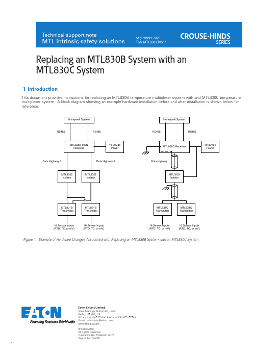
Eaton Electric Limited,Great Marlings, Butterfield, Luton Beds, LU2 8DL, UK.Tel: + 44 (0)1582 723633 Fax: + 44 (0)1582 422283E-mail:********************© 2020 EatonAll Rights ReservedPublication No. TSN838C Rev 2September 090920Replacing an MTL830B System with anMTL830C System1 Introd uctionThis document provides instructions for replacing an MTL830B temperature multiplexer system with and MTL830C temperaturemultiplexer system. A block diagram showing an example hardware installation before and after installation is shown below for reference.Figure 1: Example of Hardware Changes Associated with Replacing an MTL830B System with an MTL830C System(RTD, TC, or mV)(RTD, TC, or mV)(RTD, TC, or mV)(RTD, TC, or mV)2 Steps for replacing the MTL830B with the MTL830C system1. Record the settings if the exsiting MTL830B system.a. Record the channel configuration (thermocouple, mV, 2-wire RTD, 3-wire RTD or 4-wire RTD).b. Record the address of each MTL831B. The address is set by the positions of SW 100 switches1 and 2. NOTE: Only addresses 1 and2 are used.2. Power of the MTL830B system. This can be done by turning off or disconnecting the power to theMTL838B-HON units.3. Replace each MTL831B with an MTL831C (see the MTL831C Analog Transmitter Instruction Manual(INM MTL831C) for details).a. For hazardous area installations, confirm the Intrinsic Safety entity parameters of the sensorsare compatible with the entity parameters of the MTL831C.b. Move the wires from each MTL831B sensor input channel to the corresponding MTL831Csensor input channel.c. Each sensor input channel has 4 terminals labelled A, B, C, and D. The proper connections tothe terminals for each input type are shown in the drawing below.Figure 2: MTL 831C Terminal Connections for the Various Sensor Typesd. The extra components, terminal strips and wiring used to connect RTDs to the MTL831B arenot necessary on the MTL831C. The MTL831C supports direct connection 0f 2, 3 and 4-wireRTDs. Extra diodes for RTD measurements are not required with the MTL831C. Connect eachRTD to its own input channel port.e. Move the Data Highway cable from the MTL831B to the MTL831C. If two Data Highway cableswere used with the MTL830B system, select one of the two cables to use with the MTL830Csystem. The second Data Highway cable is not connected.f. On the MTL831C replacing the MTL831B with address 2 (if there is one), install a jumper wirebetween the ADDRESS terminals A and S (terminal numbers 7 and 8)Figure 3: Jumper Wire Between Address Terminals4. If an MTL3052 Isolator is installed in the Data Highway cable, replace the MTL3052 Isolator with theMTL5553 Isolator/Power Supplya. Shielded twisted pair Data Highway cable is highly recommended for noise immunity.b. The Isolator splits the Data Highway cable into 2 isolated sections. The shield of each section ofthe Data Highway cable must be grounded in only one location.i. Connect the shield of the section between the MTL5553 and the MTL831C to a cleaninstrument ground near the MTL5553.ii. The shield of the section between the MTL5553 and the MTL838C is grounded through the MTL838C when connections to the MTL838C are made as described below.iii. See Figure 1.c. Verify the load capacitance and inductance associated with your installation are compatible withthe MTL5553 intrinsic safety entity parameters.d. See the MTL5500 Series Instruction Manual (INM MTL5500) for details.5. Replace the MTL838B-HON with the MTL838C (see the MTL838C Receiver Instruction Manual (INMMTL838C) for details).a. Move the wires from the MTL838B-HON RS-485 ports to the corresponding terminals of theMTL838C.b. Move the wires from the MTL838B-HON Data Highway port to the corresponding terminalsof the MTL838C. If two Data Highway cables were used with the MTL830B system, connectthe same cable attached to the MTL831C Data Highway port(s) to the MTL838C Data Highwayport. The second Data Highway cable is not connected.c. Move the wires from the MTL838B-HON power port to the corresponding terminals of theMTL838C.d. A Shielded twisted pair Data Highway cable is highly recommended for noise immunity.Connect the shield to the MTL838C Data Highway connector S terminal.e. Connect one or both MTL838C GROUND terminals to a clean instrument ground.6. Apply DC power to the MTL830C system (turn on power to the MTL838C and MTL5553, if installed).7. Verify the MTL838C green POWER LED turns on.8. Verify the MTL838C green COMM LED is flashing. This indicates communication is established with theMTL831C(s). If not, verify proper connection of the Data Highway wiring.9. Install the MTL83xC Configurator software on a computer.10. Connect the computer to the MTL838C USB-C port.11. Use the software to configure the MTL838C to match the old MTL830B system settings you recorded(see the MTL83xC LLMUX Emulation manual (INM MTL83xC LLMUX) for details). On the MTL838C tab:a. Check for relevant firmware updates for the MTL831/MTL838Cb. Select LLMux as the Communication Protocol.c. Select the MTL831C transmitters that are connected (#1, #2, or both).d. Select the type of inputs connected to each MTL831C (mV/TC or RTD).e. Select the Line Frequency to 60Hz or 50Hz (frequency of power on site).f. Click the Download -> MTL838C button.Figure 4: Example MTL838C Configuration12. Use the software to configure the MTL831C(s) to match the old MTL830B system settings yourecorded.a. NOTE: The Honeywell system sends most of the channel configuration to the MTL830Csystem. However, the number of wires used for RTDs is not included in the configuration datasent by the Honeywell system. The default channel configuration for RTDs is 3-wire. If mV,thermocouple, and 3-wire RTD are the only channel configurations used then no MTL831Cconfiguration is required. If any channels are connected to 2- or 4-wire RTDs, set thosechannels using the software as described below.b. On each MTL831C tab where MTL831C is configured to measure RTDs, select the correctnumber of wires for the RTD for each channel. NOTE: this is only required for channelsconnected to 2- or 4-wire RTDs. Any channels connected to RTDs and left as “Not Configured”will be treated as 3-wire RTD when the Honeywell system enables them.c. Click the Download -> MTL831C button.d. NOTE: The MTL838C remembers the last way a channel was configured for RTD even if it islater unconfigured. if the Honeywell system then configures the channel for RTD, it will usethe number of wires that was last configured by the software. If you see unexpected behaviorwith RTDs use the software to configure the number of wires on ALL RTD channels so that you know they are correctly configured.Figure 5: Example MTL831C RTD Configuration13. Disconnect the computer from the MTL838C. NOTE: The Honeywell system will not be able to com-municate with the MTL830C system while the computer is connected to the MTL838C.14. Confirm the new system is operating properly using the Honeywell system.EUROPE (EMEA): +44 (0)1582 723633 ********************THE AMERICAS: +1 800 835 7075*********************ASIA-PACIFIC: +65 6 645 9888***********************The given data is only intended as a productdescription and should not be regarded as a legal warranty of properties or guarantee. In the interest of further technical developments, we reserve the right to make design changes.Eaton Electric Limited,Great Marlings, Butterfield, Luton Beds, LU2 8DL, UK.Tel: + 44 (0)1582 723633 Fax: + 44 (0)1582 422283E-mail:********************© 2020 EatonAll Rights ReservedPublication No. TSN MTL830x Transition Rev 2 090920September 20203 Frequently Asked Questions• Is the Data Highway cable between the transmitter and receiver required to be Fieldbus cable? No. Standard, twisted-pair instrumentation cable may be used. Shielded twisted pair is highly recommended for noise immunity.• Is there a seperate Honeywell version of the receiver, equivalent to MTL838B-HON?No. The MTL838C receiver is configurable for either standard (Modbus) or Honeywell (LLMUX) use •Can the MTL830C transmitter and receiver be used without the MTL5553 isolator, in non-IS applications?Y es. The isolator is only required for hazardous area applications •In Modbus applications, are changes needed to be programming of the Modbus master if an MTL838B is replaced by an MTL838C?No. The Modbus mapping of the MTL838C exactly the same as the MTL838B.。
6485型 皮安表
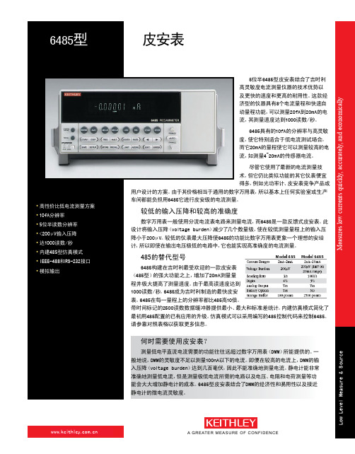
6485构建在吉时利最受欢迎的一款皮安表 (485型)的强大功能之上,增加了20mA测量量 程并极大提高了测量速度。由于最高读速度达到 1000读数/秒,6485成为吉时利制造的最快皮安 表。6485在每一量程上的分辨率都比485高10倍。 带时间标记的2500读数数据缓冲器提供最小、最大和标准差统计。内建仿真模式简化了 最初用485配置的已有应用的升级。仿真模式可以采用编写的485控制代码来控制6485。 请参靠对照表格以获取更多信息。
8501-2
8502
8503
可用到的附件:
提供的服务
低噪声BNC输入电缆,3米(10ft) 低噪声电缆套件 IEEE-488屏蔽电缆,1米(3.3ft) IEEE-488屏蔽电缆,2米(6.6ft) IEEE-488屏蔽电缆,4米(13.1ft) RS-232电缆 BNC至鳄鱼夹电缆,0.9米(3ft) 香蕉电缆组,用于模拟输出 触发链路电缆,两端接公Micro-DIN连接 器,1米(3.3ft) 触发链路电缆,两端接公Micro-DIN连接 器,2米(6.6ft) Micro-DIN至6 BNC适配盒。包含一个 8501-1 DIN至BNC触发电缆
6485-3Y-EW 从发货之日起1年工厂质保延长至3年 C/6485-3Y-ISO 从购买之日起3年内3次(符合ISO-17025
标准)校准 TRN-LLM-1-C 课程:准确进行低电平测量
*并非适用于所有国家
适配器
CS-565
BNC桶形适配器
7078-TRX-BNC 母BNC至3槽公三同轴适配器,用于连接
1.888.KEITHLEY (U.S. only) wwwww.wke.iktheliety.hcolme.cyn.c o m
- 1、下载文档前请自行甄别文档内容的完整性,平台不提供额外的编辑、内容补充、找答案等附加服务。
- 2、"仅部分预览"的文档,不可在线预览部分如存在完整性等问题,可反馈申请退款(可完整预览的文档不适用该条件!)。
- 3、如文档侵犯您的权益,请联系客服反馈,我们会尽快为您处理(人工客服工作时间:9:00-18:30)。
PN8386集成超低待机功耗准谐振原边控制器及690V高雪崩能力智能功率MOSFET,用于高性能、外围元器件精简的充电器、适配器和内置电源。
PN8386为原边反馈工作模式,可省略光耦和TL431。
内置高压启动电路,可实现芯片空载损耗(264VAC)小于50mW。
PN8305封装及脚位配置图
PN8305包括同步整流控制器及N型功率MOSFET,用于在高性能反激系统中替代次级整流肖特基二极管。
PN8305内置电压降极低的功率MOSFET以提高电流输出能力,提升转换效率并降低芯片温度。
2.PCB及DEMO实物图
3.方案典型应用图
4.方案特性
·PCBA尺寸:42.5mm*41.3mm*20mm
·输入电压:90~265Vac全电压
·输出电压:5V
·输出电流:3A
·平均效率:≥81.4%(满足六级能效要求)
·高压启动待机功耗<75mW
·启动时间:<200ms(90Vac)
·拥有输出短路保护,输出过流保护,输出欠压保护(PCB端3.1V以下),VDD过压保护,FB分压电阻开路短路保护,以及电流检测电阻Rcs开短路保护,过温保护。
5.测试数据
备注:在CC工作状态下且系统PCB电压低于3.1V时,PN8386会进入保护状态。
6.EMC测试
·EMI传导、辐射满足EN55022Class B标准要求,裕量均大于6.0dB
·ESD满足IEC61000-4-2,8kV/15kV等级要求
·EFT满足IEC61000-4-4:2004,4kV等级要求
·Surge满足IEC61000-4-5:2005,1kV等级要求
·交流绝缘满足3.75kV,60s,漏电流小于5mA要求
7.应用要点
PN8386工作在DCM模式,忽略传输瞬态Tr和Tf,导通时间、去磁时间和振荡时间分别为:
PN8386在T2时间内间接采样输出电压信号,为减小漏感振荡对采样的影响,最小T2时间应足够长(5V3A应用建议大于3.2us):
备注:电源在小负载工况下,PN8386的Vcs=0.17V以避免音频噪音。
PN8305须在T2时间内完成Trench MOSFET的开通和关断,其最小导通时间由RT电阻设定:
因此,RT电阻建议取值为:
本文由大比特资讯收集整理()。
