AW-BM1600-8A安装编程手册(经济实用增强型)
AW-BM1600大型总线网络报警控制管理主机
AW-BM1600大型总线网络报警控制管理主机重要特色●业内最大报警主机,单台主机最多1008个防区●32个子系统,32个自动布撤防工作表●60个时间表驱动180个事件自动执行●按系统/子系统/防区分别独立控制●多种可编程智能内部联动预案●可编程定时输出控制或手动输出控制●600多组用户密码●2944条详细的历史事件记录●全双工串行口多媒体在线设置与管理●按照专业标准设计的大型报警控制主机●通过国家安防产品认证中心3C认证●超大适应范围,灵活的扩充架构●独创的多用户多子系统控制管理机制●高度智能化和便利的综合集成控制与处理能力●整合报警、巡更于统一硬件系统平台●安装调试、使用、维护简便主要特性●采用纯硬件嵌入式系统设计,32位ARM7处理器,16K RAM,64K FLASH●具备4条防区扩展485总线接口和一个独立的RS232通信端口●可扩展一个RS485或以太网接口用于更多主机联网组建超大型报警系统●自带16个防区,可通过485总线扩充62个不同类型模块,共有16种总线扩充模块类型可供选择●独立显示每个子系统工作状态,每个子系统独立撤布防,每个子系统独立设置自动撤布防工作时间表段●带各种保护的超大负载能力辅助电源输出,适应不同环境下使用●支持对各种系统设备的监测与管理●64台AW-BM1600主机挂接在一条485总线上使用●可扩展以太网络双向数据通信控制管理,适应通过各种IP网络组建联网报警系统●系统采用多级密码管理机制,最多可设置602组用户密码●通过控制键盘独立完成所有功能操作与编程设置,允许一个主控键盘和多个分控键盘对系统进行控制●支持控制键盘与RS232串口同时独立控制,利用多媒体软件作为更加直观的辅助管理与控制手段●独特的分控键盘用户密码登陆机制,在同一分控键盘上通过登陆不同的分控密码分别操控相应的子系统●灵活的防区报警联动设置,支持每个防区任意设定2个模块的2个输出进行联动,满足各种智能化个性需求●支持子系统报警、未准备、布防、撤防、故障任意联动输出预案设置●可扩展电话线/GSM无线语音和ADEMCO CONTACT ID数据报警通信功能●超强事件记忆能力,自动详细记录最新发生的2944条事件,可通过键盘或管理软件读取查阅●完善的过流、过压保护措施,485总线采用三级桥式防雷保护电路设计,系统可靠性高●超强稳定性和各种环境适应性,两年免费质量保证,众多楼宇、文博、司法系统成功应用案例●便于第三方软件系统集成,免费提供完善的系统设置与各种控制管理SDK开发包技术参数电压输入:交流17V输入,配套变压器技术规格为17V输出、额定功率60W,带交流断电监视辅助电源输出:13.8V/ 最大2A,带输出短路保护措施主机板功耗:160mA外接电池:2组并联的备用电池接口,带过流保护,推荐使用12V/7AH电池,负载电流较大时建议连接2组电池电池充电电压:直流13.8V,带电池电压检测及过放电保护,电池放电保护电压10.5V警号输出:直流13.8V, 最大1.8A,带过流保护外部通信端口:一个RS232端口或扩充上行485/以太网络的扩展接口;4个485总线扩充设备端口485总线通信接口:2线半双工485通信协议:MODBUS工业控制器网络通信协议总线扩充设备数量:62个电话线通信:一个电话线通信扩充接口,支持语音/CID格式数据报警通信,2个语音/2个数据号码用户密码:安装员码1组,管理员码1组,系统操作员码78组,分控操作员码512组,胁迫码10组主机基础防区:16个带2K线末电阻的标准防区防区扩充数量:992个防区类型:出入、防拆、内部、周边、煤气、火警、锁定型/非锁定型锁匙、24小时无声/有声、医疗救护、非报警子系统数量:32个时间表数量:60个事件存储容量:2944条工作温度:-20℃-50℃工作湿度:不大于90%,非凝露机箱尺寸:380mm×320mm ×85mmAW-BK00C 中文LCD系统控制键盘●嵌入式系统设计,32位ARM7处理器,16K RAM,64K FLASH●直流10-28V供电,具备反接保护,50mA工作电流●超大中文LCD带文字信息和系统时间日期显示屏●灵巧的4个快捷功能键和5个导航操作键设计,各项操作灵活便捷●连接在扩充设备总线上,通过内部拨码开关地址区分主控或分控键盘●每台主机允许设置一个主控键盘和最多8个分控键盘●分控键盘采用用户登陆机制,通过登录不同的用户,分别控制相应的子系统●可分别按系统/子系统/模块/防区查看运行状态,并可分别按系统/子系统/模块/防区独立操作控制●系统报警信息显示与报警音频提示,系统内各设备运行状态显示与状态查询●系统设备故障状态显示与提示,对系统各种设备进行参数设置●系统各项事件记录信息查询AW-NC200M 网络通信接口模块●专门配套AW-BM1600使用的工业级网络通信接口●直接插入主机板相应插座即可扩充出一个以太网接口●利用AW-NC200M可以轻松实现报警管理主机接入网络,并可与SIMS2000综合安防集成管理软件进行各种数据的双向通信,解决多台主机通过各种IP网络联机的工作方式,通过SIMS2000软件对主机进行各种参数设定与在线实时控制管理特性描述硬件特性32位ARM7 CPU,64K RAM,128K FLASH网络参数100 Mbps以太网接口,1.5KV电磁隔离工作模式TCP Server、TCP Client、UDP和Real Com等,目标IP和端口均可设置工作环境-20ºC~50°C/不大于90%,非凝露外形尺寸50mm×38mmAW-BIX01/02单防区单输出/二防区总线通信模块●AW-BIX01是带1个2K线末电阻接线防区和1路集电极开路输出(不大于200mA)的总线扩充模块●AW-BIX02为带2个2K线末电阻标准接线防区的总线扩充模块●体积小巧, 可放置在诸如主动红外对射类型的探测器内,非常适合在周界报警系统中使用●硬件看门狗功能,防雷、过流、过压多重保护措施主要技术指标AW-BIX04/08/16四/八/十六防区总线通信模块主要技术指标模块类型AW-BIX04 AW-BIX08 AW-BIX16工作电源/电流10V-28V直流/25mA 10V-28V直流/40mA10V-28V直流/60mA防区数量4个带2K线末电阻接线防区8个带2K线末电阻接线防区16个带2K线末电阻接线防区防区类型出入、防拆、内部、周边、煤气、火警、锁定型锁匙、非锁定型锁匙、24小时无声/有声、医疗救护、非报警特性描述特性描述工作电源/电流10V-28V直流,具备反极性保护/20mA 485地址方式/范围六位拨码开关/01~63防区监控保护2KΩ±30%线末监控电阻工作温度/湿度-20ºC~50°C/不大于90%,非凝露防区类型出入、防拆、内部、周边、煤气、火警、锁定型锁匙、非锁定型锁匙、24小时无声/有声、医疗救护、非报警可编程输出AW-BIX01输出端口可编程对应自身输入防区实现报警输出,或编程为接收外部控制,实现中心手动控制或响应其它模块报警联动输出。
micro-motion(高准)1600 以太网变送器 - 安装手册 - 中文说明书
安装手册00825-0106-1600, Rev AC2022 年 10 月Micro Motion™(高准)1600 以太网变送器以太网安装安全信息本手册提供的安全信息用于保护人员和设备。
在进行下一步操作前,请仔细阅读每条安全信息。
安全和认证信息如按照本手册中的说明正确安装,则高准产品符合所有适用的欧洲指令。
请参阅 EU 符合性声明,以了解本产品适用了哪些指令。
附带以下文档:针对所有相关欧洲指令的 EU 符合性声明,以及全套 ATEX 安装图纸和说明书。
此外,还可以访问或通过您的当地高准支持中心,获取适用于欧盟以外地区安装的 IECEx 安装说明以及适用于北美地区安装的 CSA 安装说明。
符合压力设备指令的设备所附的信息可通过获取。
在欧洲的危险环境安装,如果本国没有相关标准,则可参考标准 EN 60079-14。
其他信息如需获得故障排查信息,请参阅组态手册。
产品样本和手册可从高准网站获取。
退货政策退回设备时必须遵循高准程序。
遵循这些程序可确保符合政府运输机构的法规要求,同时有助于为高准员工提供安全的工作环境。
如不遵守高准规程,高准将不会接受您退回的设备。
有关于返修程序和返修表格,请登录获取,或致电高准客户服务部门获取。
2安装手册内容00825-0106-16002022 年 10 月内容第章1开始之前 (5)1.1 关于本手册 (5)1.2 风险说明 (5)1.3 相关文档 (6)第章2安装准备 (7)2.1 安装检查表 (7)2.2 改装现有安装的其他注意事项 (8)2.3 电源要求 (9)2.4 以太网网络中的 1600 型变送器 (10)第章3安装和传感器接线 (13)3.1 一体化安装变送器安装和传感器接线 (13)3.2 安装变送器 (13)3.3 分体式变送器与传感器的接线 (13)3.4 仪表部件接地 (15)3.5 旋转传感器上的变送器(可选) (17)3.6 旋转变送器显示器 (17)3.7 旋转分体式变送器上的 1600 变送器外壳(可选) (18)第章4通道接线 (21)4.1 可用通道 (21)4.2 I/O 通道接线 (21)4.3 以太网通道接线 (27)第章5电源接线 (31)5.1 VDC 电源接线 (31)5.2 连接以太网供电 (PoE) 电源 (32)5.3 使用 M12 端头电缆(可选)进行电源接线 (33)第章6设置打印机 (35)6.1 通过更改打印机默认 IP 地址来设置打印机 (35)6.2 使用打印机默认 IP 地址来设置打印机 (37)6.3 复位接口设置 (38)6.4 功能检查失败 (38)第章7接通变送器电源 (39)第章8设置向导 (41)第章9变送器显示器的组件 (43)安装手册3内容安装手册2022 年 10 月00825-0106-16009.1 访问和使用显示菜单 (44)第章10可用服务端口连接 (49)附录 A将 1600 连接到 3100 继电器 (51)4 Micro Motion(高准)1600 以太网变送器1开始之前1.1关于本手册本手册提供有关高准 1600 以太网 变送器规划、安装、接线和初始设置的信息。
1600编程布防
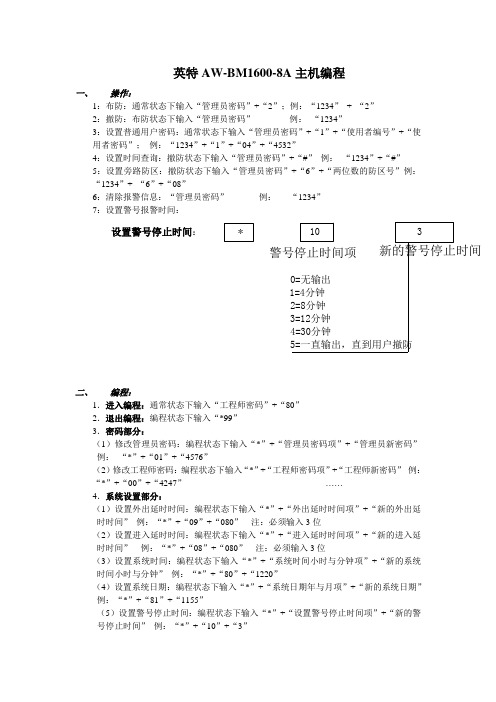
英特AW-BM1600-8A主机编程一、操作:1:布防:通常状态下输入“管理员密码”+“2”;例:“1234”+ “2”2:撤防:布防状态下输入“管理员密码”例:“1234”3:设置普通用户密码:通常状态下输入“管理员密码”+“1”+“使用者编号”+“使用者密码”;例:“1234”+“1”+“04”+“4532”4:设置时间查询:撤防状态下输入“管理员密码”+“#”例:“1234”+“#”5:设置旁路防区:撤防状态下输入“管理员密码”+“6”+“两位数的防区号”例:“1234”+ “6”+“08”6:清除报警信息:“管理员密码”例:“1234”7:设置警号报警时间:设置警号停止时间: * 10 3警号停止时间项新的警号停止时间0=无输出1=4分钟2=8分钟3=12分钟4=30分钟5=一直输出,直到用户撤防二、编程:1.进入编程:通常状态下输入“工程师密码”+“80”2.退出编程:编程状态下输入“*99”3.密码部分:(1)修改管理员密码:编程状态下输入“*”+“管理员密码项”+“管理员新密码”例:“*”+“01”+“4576”(2)修改工程师密码:编程状态下输入“*”+“工程师密码项”+“工程师新密码”例:“*”+“00”+“4247”……4.系统设置部分:(1)设置外出延时时间:编程状态下输入“*”+“外出延时时间项”+“新的外出延时时间”例:“*”+“09”+“080”注:必须输入3位(2)设置进入延时时间:编程状态下输入“*”+“进入延时时间项”+“新的进入延时时间”例:“*”+“08”+“080”注:必须输入3位(3)设置系统时间:编程状态下输入“*”+“系统时间小时与分钟项”+“新的系统时间小时与分钟”例:“*”+“80”+“1220”(4)设置系统日期:编程状态下输入“*”+“系统日期年与月项”+“新的系统日期”例:“*”+“81”+“1155”(5)设置警号停止时间:编程状态下输入“*”+“设置警号停止时间项”+“新的警号停止时间”例:“*”+“10”+“3”5.防区部分:。
FMA-1600A系列气体流量计说明书
Mass and Volumetric Gas Flow MetersFor Clean GasesU U p to 18 Hour Battery Charge on Portable“-B” Models U R anges of 0 to 0.5 SCCM Up to 0 to 3000 SLM U R eports Mass Flow, Volumetric Flow,Temperature, and Pressure U <10 ms Response Time—Field Adjustable U 130+ Gas Calibrations IncludingPure and Mixed Gases U P ressure, Temperature and Volumetric orMass Flow Simultaneously Displayed U N IST 5-Point Certificate Included U N o Straight Runs of Pipe Required U No Warm-Up TimeU Turndown Ratio of 200:1 (0.5% Maximum Flow)U RS232 StandardU Custom Live Gas Blend Programming U Store Up to 20 User Defined Gas BlendsThe FMA-1600A Series mass and volumetricflow meters use the principle of differential pressure within a laminar flow field to determine the mass flow rate. A laminar flow element (LFE) inside the meter forces the gas into laminar (streamlined) flow. Inside this region, the Poiseuille equation dictates that the volumetric flow rate be linearly related to thepressure drop. A differential pressure sensor is used to measure the pressure drop along a fixed distance of the LFE. This, along with the viscosity of the gas, is used to accurately determine the volumetric flow rate. Separate absolute temperature and pressure sensors are incorporated and correct the volumetric flow rate to a set of standard conditions. This standardized flow rate is commonly called the mass flow rate and is reported in units such as standard cubic feet per minute (SCFM) or standard liters per minute (SLM).Standard units include a 0 to 5V output (4 to 20 mA optional) and RS232 communications. The gas select feature can be adjusted from the front keypad or via RS232 communications. Volumetric flow, mass flow, absolute pressure, and temperature can all be viewed or recorded through the RS232 connection. It is also possible to multi-drop up to 26 units on the same serial connection to a distance of 38 m (125'). These flow meters are available in a portable version (“-B” option), the battery charge will last up to 18 hours.FMA-1600A SeriesSpecificationsAccuracy: ±(0.8% of rdg + 0.2% FS)Repeatability: ±0.2%Turndown Ratio: 200:1Response Time: 10 ms typical default response time for 63.2% of a step change. A variable register allows response time to be field adjustable to a certain extent via RS232 communications. The primary trade-off for response time is signal noiseOutput: 0 to 5 Vdc standardOperating Temperature: -10 to 50°C (14 to 122°F)Zero Shift: 0.02% FS/°C/atm Span Shift: 0.02% FS/°C/atmHumidity Range: 0 to 100% non-condensing Pressure (Maximum): 145 psig Measurable Flow Rate: 125% FSSupply Voltage: 7 to 30 Vdc (15 to 30 Vdc for 4 to 20 mA output)Supply Current: 35 mA typical current draw; 100 mA available supply recommended Cable Connection: 8-pin mini DINWetted Parts: 302 and 303 SS, FKM, heat cured silicone RTV, glass reinforced PPS, heat cured epoxy, aluminum, gold, brass, 430 FR stainless (416 stainless steel on large sizes), silicon, glassFMA-1603A includes 110 Vac power supply and a 1.8 m (6') cable 8-pin mini DIN connector,Shown smaller than actual size.Exploded View of InternalLaminar Flow Elements Absolute PressureSensorDifferential PressureSensor TemperatureSensorProgram Custom Mixed Calibrationsfor Bioreactors, Chromatography,Welding, Lasers, Stack/Flue, Fuel Gases and MoreComes complete with 24 Vdc universal power supply, 1.8 m (6') cable, 8-pin male Mini-DIN connector, operator’s manual, and NIST certificate. Units are calibrated to air @ 5 psig for 0 to 1 LPM, 15 psig for 2 to 10 LPM, 30 psig for 20 to 100 LPM, and 50 psig for 200 LPM and greater. Calibrations done at ambient 25ºC (77ºF) temperature only.To replace the standard RS232 communications with RS485, add suffix “-RS485” to the model number; for additional cost.Standard input is 0 to 5V, for optional 4 to 20 mA input add suffix “-IN” to the model number; no additional cost.Standard output is scaled to the mass flow rate. For volumetric flow rate as standard output add suffix “-VOL” to the model number; no additional cost. Standard output is 0 to 5V, for optional 4 to 20 mA output, add suffix, “-I” to model number; for additional cost.For two 4 to 20 mA output, add suffix “-I2” to model number; for additional cost.For two 0 to 5V output, add suffix “V2” to model number; for additional cost.**Optional secondary output are scaled the same as the primary output scale. For an alternate output scale add suffix “-T” to the model number for temperature or “-P” for pressure; no additional cost.For a portable version of the meter add suffix “-B” to the model number; for additional cost. Portable versions have an integral battery on the meter and come with one 9V battery installed. Option not available on “-I” or “I2” models where 4 to 20 mA is the chosen output.For units scaled in SCFH, add suffix “-SCFH” to model number; no additional cost. Please specify the desired range in SCFH.For totalizer option, add suffix “-TOT” to the model number; for additional cost. Please specify resolution.This is a 6-digit counter. Examples: For totalizing in liters with 1/100 liter resolution, the max count would be 9999.99. For totalizing in liters with 1 liter resolution, the max count would be 999999.Ordering Examples: FMA-1601A, 0.5 SCCM mass flow meter.FVL-1619A-VOL, 500 SCCM volumetric flow meter.。
英安特8-16防区主机.doc
AW-BM1600-8A/AW经济/实用型/增强型报警通信控制器可编程防区特性●主机具备4个/8个/16个标准接线防区,4个键盘紧急防区。
●每个接线防区均可设置为包括出入口、防拆、内部、周边、煤气、火警、24小时无声劫持、24小时有声紧急、医疗求助、锁定型锁匙布撤防防区、非锁定型锁匙布撤防防区、非报警输入、24小时盗警防区13种类型之一。
●可扩展无线防区,通过编程设置确定各防区是否启用无线接入,可与各种国产无线探测器配套使用。
AW-RC无线遥控匙扣AW-VOC语音及遥控模块AW-BRK分控读卡模块AW-ICK卡/匙扣(相当于CROW的CI卡)四建AW-OX08AW-OX16AW-GCRM AW-GCR实时监控电话线状态,当电话线发生故障或被剪断时,自动切换到GSM 工作模式取代电话线发送报警讯息AW-232I RS232接口扩展模块 AW-NC100M 网络通信接口扩展模块AW-RC 无线遥控匙扣返回●可配套8AW 无线型主机及BK04/08/16CW 无线型报警控制键盘使用,实现无线遥控功能 ●共有布防、撤防、无声紧急报警、有声紧急报警四个遥控按钮●良好的防水性能●采用SMT 进口贴片元件,声表面谐振器稳频AW-VOC 语音及遥控模块 返回 ●内置铃流检测与音频解调电路,接收远程电话键盘遥控命令,实现远程话机遥控主机撤布防●内置20秒固态语音存储芯片,实现报警语音录AW-BRK 分控读卡模块 可连接4个●四层电路板设计双面表贴,EMC 性能优良●设计紧凑体积小巧,读卡操作蜂鸣器声音提示返回AW-ICK IC 卡/匙扣返回●由ABS 外壳封装芯片和线圈并填充环氧树脂,通过超声波焊接组合 ●标准IC 卡或各种造型的异形卡可选●MF 系列芯片。
●蓝色,可定制其它颜色 ●可丝印图标、喷码 ●防水、防尘、抗震动 ●工作环境:-20ºC~50°C/不大于90%,非凝露 AW-OX08八路可编程输出控制模块返回 ●连接在8A 主机的键盘总线上,主机根据每一个端口的编程设置进行输出控制,最多可连接4个AW-OX16十六路可编程输出控制模块返回●连接在8A 主机的键盘总线上,主机根据每一个端口的编程设置进行输出控制,最多可连接4个 ●提供16路集电极开路可编程控制输出端AW-GCRMGSM 无线通信模块返回●AW 路板上即可工作,接受主机系统软件的统一管理与控制,并和电话线路传输通道一起按照编程设置的策略进行各种信息的传输报告(支持CONTACT ID 数据/语音/短信三种方式)。
CED1600 快速入门指南说明书
• Never connect speaker wires to the metal body or chassis
11 SUB-W OUT (Blue Sub-woofer socket)
12 REVERSE CAMERA Reverse camera (B+) (Purple wire)
13 PARKING BRAKE (Pink wire)
Parking brake (-)
14 OE SWC IR REMOTE OE SWC remote in IN (Brown wire)
• Make sure that all loose leads are insulated with electrical
tape.
• Make sure that the leads do not get caught under screws or
in parts that will move (e.g. seat rail).
• Consult a professional to connect wires as instructed below. • Before connection, check the car's wiring carefully.
1 Connect the ISO male connectors. (1-1)
ISO male connectors
Connect to
a Green strip, black- Rear left speaker edged green strip
单防区单输出总线通信模块 AW-BIX01 安装说明
AW-BIX01是连接在AW-BM1600大型总线报警主机扩充总线上使用的总线通信扩充模块,提供1个标准接线防区输入和一路集电极开路输出,输出端口可通过编程设定自身联动输出(即对应本身的输入防区实现报警联动)和外部控制输出两种工作模式,外部控制支持手动命令控制输出和可编程的报警联动输出控制模式。
其很小的体积足以直接放置在某些体积较大的探测器中,因此AW-BIX01更加适合在防区比较分散又需要一一对应进行现场联动的报警系统中使用。
另外,AW-BIX01使用和维护简单方便,只需通过拨码开关设置一个485地址接入总线系统中即可使用。
主要性能工作电源:直流10-28V,具备反极性保护工作电流:约20mA防区输入:1个带2K线末电阻标准接线防区防区类型:包括出入口、防拆、内部、周边、煤气、火警锁匙布撤防、24小时无声紧急、24小时有声紧急防区监控保护:2KΩ±30%线末监控电阻联动输出:单路集电极开路输出(驱动能力不大于200mA),实现一一对应现场联动通信接口:两线485总线通信接口通讯协议格式:MODBUS工业控制器网络通信协议485地址方式:六位拨码开关485地址范围:01~62LED通信状态指示体积小,可放置在某些探测器内无需编程,在主机中登记后即可使用工业级芯片,可适合户外使用支持防区旁路功能硬件看门狗功能防雷保护措施工作温度:-20ºC~50°C工作湿度:不大于90%,非凝露外形尺寸:60mm X 20mm警告:通电前一定要确保输出端不可裸露,否则容易导致输出短路而使内部电路永久损坏。
模块与管理主机接线规范请参照管理主机安装说明的相关章节。
附:485地址拨码表地址拨码 1 2 3 4 5 678910111213 14 15 1617181920211 On Off On off On Off On Off On Off On0ff0n 0ff 0n 0ff On Off On off On2 Off On On Off Off On On Off Off On On0ff0ff On 0n 0ff Off On On Off Off3 Off Off Off On On On On Off Off Off Off0n0n 0n 0n 0ff Off Off Off On On4 Off Off Off Off Off Off Off On On On On On0n 0n 0n 0ff Off Off Off Off Off5 Off 0ff Off Off Off Off Off Off Off Off Off0ff0ff 0ff 0ff 0n0n0n0n0n0n6 Off 0ff 0ff 0ff 0ff 0ff0ff0ff0ff0ff0ff0ff0ff 0ff 0ff 0ff Off0ff0ff0ff0ff 拨码22 23 24 26 26 2728293031323334 35 36 3738394041421 Off On Off On Off On0ff0n0ff0n0ff On Off On off On Off On Off On Off2 On On Off Off On On0ff0ff On0n0ff Off On On Off Off On On Off Off On3 On On Off Off Off Off0n0n0n0n0ff Off Off Off On On On On Off Off Off4 Off Off On On On On On0n0n0n0ff Off Off Off Off Off Off Off On On On5 0n 0n 0n 0n 0n 0n0n0n0n0n0ff Off0ff Off Off Off Off Off Off Off Off6 0ff 0ff 0ff 0ff 0ff 0ff0ff0ff0ff0ff0n On0n 0n 0n 0n0n0n0n0n0n 拨码43 44 45 46 47 4849505152535455 56 57 5859606162631 On 0ff 0n 0ff 0n 0ff On Off On off On Off On Off On Off On0ff0n0ff0n2 On 0ff 0ff On 0n 0ff Off On On Off Off On On Off Off On On0ff0ff On0n3 Off 0n 0n 0n 0n 0ff Off Off Off On On On On Off Off Off Off0n0n0n0n4 On On 0n 0n 0n 0ff Off Off Off Off Off Off Off On On On On On0n0n0n5 Off 0ff 0ff 0ff 0ff 0n On On On On On On On On On On On On On On On6 0n 0n 0n 0n 0n 0n On0n0n0n0n0n0n 0n 0n 0n0n0n0n0n0n。
威力巴 V150 VERIS 安装和维护手册说明书
V150 VERIS 威力巴®安装和维护手册164-CN请阅读并保存以下说明目录安全信息介绍产品信息 (3)第 1 节:适用范围本手册的目的 (3)第 2 节:收货检验收货检验威力巴® (3)第 3 节:安全预防 (3)第 4 节:安装前的准备 ...................................................................3-5安装位置 (3)安装方向 (4)水平管道 (4)垂直管道 (5)差压变送器/现场指示器位置 (5)安装图示和材料清单 (5)第 5 节:安装步骤..........................................................................6-9准备管道 (6)接头焊接............................................................................................................6-7弹簧锁定装置 (7)插入探头............................................................................................................7-8安装仪表阀门或阀组 (9)阀门 (9)阀组 (9)管道试压 (9)第 6 节:正确安装 (10)第 7 节:定期维护 (10)有限保修和补救措施 (11)2设计、材料、重量及性能等级为近似值,如有变更,恕不另行通知。
有关最新信息,请访问armstrong 。
3设计、材料、重量及性能等级为近似值,如有变更,恕不另行通知。
有关最新信息,请访问 armstrong 。
第 1 节 适用范围以下说明是 V150 型威力巴®流量探头的安装步骤。
INANTERSIMS帮助
INANTER-SIMS2000综合安防集成管理平台安装说明本用户手册没有任何形式的担保及承诺。
若因此用户手册或者是所提及的产品信息,而引起的直接或间接的数据丢失、利益损失或事业终止,或者是因任何安装使用不当造成的直接、间接、有意、无意损坏及隐患,英安特公司及所属员工恕不为其担负任何责任。
此外,本手册所提及的软件功能仅供参考,本手册可能包含技术上不准确的地方或印刷错误。
我们将会随时改进或更新本手册中描述功能或程序,本手册的内容也将做定期的版本更新,恕不另行通知,更新的内容将会在本手册的新版本中加入。
本手册涉及的各种名称仅做识别之用,这些名称可能属于其他公司的商标或版权。
目录INANTER-SIMS2000最终用户软件许可协议 (5)前言 (9)一、参考材料以及书目 (9)二、INANTER-SIMS2000软件运行环境要求 (9)三、数据库系统 (10)SIMS2000综合安防网络集成管理平台简介 (11)如何应用SIMS2000综合安防网络集成管理平台 (12)一、二级中心应用 (12)二、一级中心应用 (13)安装SIMS2000综合安防网络集成管理平台的条件 (13)第一章MS SQL Server 2000个人版数据库安装 (14)第二章MS SQL Server 2000 SP4补丁安装 (23)第三章MS SQL Server 2000 SP4 补丁安装后的网络测试 (32)3.1 看ping 服务器IP能否ping通 (32)3.2 在DOS或命令行格式下的测试 (32)3.3 检查客户端设置 (33)3.4 企业管理器或查询分析器连接测试 (34)3.5 错误产生的原因 (34)第四章INANTER-SIMS2000 软件安装 (35)第五章INANTER-SIMS2000 数据库安装 (41)5.1 自动安装数据库 (41)5.2 手动安装数据库 (42)第六章软件授权设备的安装 (45)第七章INANTER-SIMS2000 软件服务的安装 (46)7.1 安装及启动软件授权服务 (46)7.2 安装及启动安装语音服务器 (46)7.3 安装及启动SIMS2000-RMS注册服务器 (46)7.4 安装及启动SIMS2000-VBUS通讯服务器 (46)第八章INANTER-SIMS2000 平台软件操作使用说明 (47)8.1 运行前的准备 (47)8.2 SIMS2000-RMS注册服务器(仅在大联网时使用) (47)8.3 SIMS2000-Config设置管理系统 (48)8.3.1 站点授权 (49)8.3.2 电子地图 (50)8.3.3 报警管理 (55)8.3.4 模拟矩阵 (67)8.3.5 数字视频 (71)8.3.6 巡更管理 (76)8.3.7 门禁管理 (79)8.3.8 对讲管理 (81)8.3.9 系统用户 (84)8.4 SIMS2000-VBUS Service通讯服务器 (87)8.4.1 系统设置 (88)8.4.2 事件日志 (88)8.4.3 报警系统 (89)8.4.4 巡更系统 (90)8.4.5 模拟矩阵 (90)8.4.6 门禁系统 (91)8.4.7 对讲系统 (93)8.5 SIMS2000综合安防网络集成管理平台 (94)8.5.1 软件登录 (94)8.5.2 界面按钮介绍 (95)8.5.3 电子地图 (95)8.5.4 报警系统 (96)8.5.5 模拟矩阵 (97)8.5.6 数字视频 (98)8.5.7 扩展工具 (100)8.5.8 查询历史记录 (100)第九章系统故障珍断 (104)9.1 Generic Host Process for Win32 Services 错误 (104)9.2 Windows 安全警报 (106)(一) 关闭Windows XP的防火墙 (106)(二) 将应用程序添加到windows防火墙例外设置中 (110)第十章网络模块设置 (113)10.1 AW-NC100及AW-NC200M设置 (113)10.2 IP2000的编程及设置 (117)10.3 IPM的编程及设置 (119)10.4 DVSAlarm的设置与使用 (123)第十一章一级中心联网络系统安装 (123)11.1 安装概述 (123)11.2 一级中心与二级中心联网示意图 (124)11.3 二级中心的设置 (124)11.4 一级中心安装MS SQLSERVER数据库 (125)11.5 一级中心软件安装 (125)11.6 一级中心软件运行设置步骤 (132)INANTER-SIMS2000最终用户软件许可协议重要须知——请认真阅读本《最终用户许可协议》(一下称《协议》)是您(个人或单一机构团体)与南京英安特科技实业有限公司(以下简称英安特)之间有关上述INANTER-SIMS2000“软件产品”的法律协议。
LT800安装手册v2.0 20100916
LT800 安装手册
安装手册
本文介绍了 LT800 基站安装方法、规范等
工程技术部 重庆无线绿洲通信技术有限公司 2010-9-12
目录
目录........................................................................................................................................... 2 图表目录................................................................................................................................... 3 1 概述................................................................................................................................... 4 2 安装流程........................................................................................................................... 6 2.1 安装准备工作................................................................................................................... 6 2.2 安装工具准备........................
NC100M调试说明
设置网络模块
1、运行网络模块设置工具,出现如下界面
第一步、选择“新版NC200M”
第二步、点击“搜索”按纽
设置网络模块
找到网络模块了,双击列表中的IP地址
设置网络模块
网络模块的参数信息显示出来了
[1] [2] [3] [4] [5] [8] [7] [9]
[6]
一定要确认参数信息正确后再点击提交修改
如何关闭防火墙 在上图中将“启动类型(E)”改为“已禁止”,如果“服务状态”为“已启 动”,请点击“停止(T)”按纽,再点击“应用(A)”,最后点击“确定”退 出该服务属性设置。再找到“Windows Firewall/Internet Connection Sharing (ICS)”项,如下图:
编程工具
如上图所示,数据读取成功后,会将原来主机中设置过的 编程项一一显示出来
编程工具
如果需要修改报警主机中的某项编程项,只需要用鼠标选中 该项,然后在下拉列表中选择对应的数值或者输出需要的数 值即可。 需要修改的编程项修改完毕后,点击“提交数据”,输入工 程师密码,然后耐心等待进度条走完即可。 如果需要将设置好的参数保存下来,点击下方的“导出设置 “”
如何关闭防火墙 双击该项,弹出属性设置, 将“启动类型(E)”改为“已禁止” 。如 果“服务状态”为“已启动”,请点击“停止(T)”按钮,再点击“应 用(A)”,最后点击“确定”退出该服务属性设置。如下图:
Thanks
,弹出下图
如果发送数据和接受数据框中一直有数据在走,说明软件和报 警主机通讯一切正常,在此处可以判断出网络的通畅情况
编程工具
点击
,弹出下图
输入工程师密码(出厂默认1600),点击确定进入历史 记录查询界面,如下图:
PMA-1600NE - 操作说明书
PMA-1600NEINTEGRATED AMPLIFIER操作说明书可在单页纸张上打印多个PDF页面。
附件4安装电池5遥控器的操作范围5特点6高音效6高性能6部件名称与功能7前面板7后面板10遥控器12连接方法连接扬声器17扬声器连接19双线分音连接方法20连接播放设备21连接录音设备22连接带有数字音频输出端子的设备23连接计算机或Mac24连接电源线25播放开启电源27选择输入源28调节主音量28暂时关闭声音(静音)28调节音调28切换显示屏亮度29播放CD29连接和播放计算机(USB-DAC)31连接和播放数字设备(同轴/光纤)40录音41设置设置自动待机模式42开启自动待机模式42关闭自动待机模式42提示提示44故障诊断45保修和修理51附录数模转换器52术语解释52商标信息53规格54索引57感谢您购买本Denon产品。
为了确保正确操作,请在使用本品前认真阅读本操作说明书。
阅读之后,请务必妥善保管以备将来参考。
附件请检查并确认本产品附带下列部件。
安装电池1沿箭头所示方向抬起并取下后盖。
2按照指示将两节电池正确插入电池匣内。
3装上后盖。
注0为防止损坏电池或电池漏液 :0请勿将新旧电池混合使用。
0请勿使用两种不同类型的电池。
0如果打算长时间不使用遥控器,请取出遥控器中的电池。
0如果电池漏液,须仔细地擦去电池匣内的漏液,然后装入新电池。
遥控器的操作范围操作遥控器时应将其指向遥控感应窗。
特点高音效0高级UHC-MOS单推挽电路功率放大器输出级采用UHC-MOS FET。
稳态电流为30 A,瞬时电流为120 A。
通过使用双FET选择的第一阶段电压放大级,提高了受温度波动影响的操作稳定性。
此外,通过使用级联自举电路相性被稳定到高频。
0电源为了充分利用高级UHC-MOS单推挽电路,本强大电源由搭载双变压器的LC、具有高电流容量的肖特基势垒二极管以及用于高音质的定制块式电容器所组成。
0机械接地具有各信号电平屏蔽的6个离散块和由高密度材料构成的机箱脚的机箱追求机械接地的概念,消除了由外部振动引起的干扰,并可防止变压器的振动、内部振动源被传递到放大器电路。
PE51单片机增强型学习系统使用说明书
51单片机加强型学习系统i s o n e o f t h e p r a c t i c a l f o r m o f v a l u e s . T h e s o -c a l l e d v a l u e s r e f e r s t o t h e o b j e c t i v e t h i n g s a r e o f n o v a l u e a n d t h e v a l u e o f f u n d a m e n t a l p e r s p e c t i v e .D i f f e r e n t v a l u e s ,p e o p l e 's b e hav io ur ,a ttit ud es ,w ay sa re di ff er en t.P e o p l e -o r i e n t e d f o c u s o n h u m a n v a l u e a n d r e a l i t y ,w e n e e d t h e b r oa d e s t m a s s e s a s v a l u e s .A d h e r e t o p e o p l e -o r i e n t e d val ues ,is tom ake the eco nom ymo red eve l o p m e n t ,i m p r o v e d e m o c r a c y ,c u l t u r a l p r o s p e r i t y ,a n d l i v e a h a p p i e r ;i s d e e p l y c o n c e r n e d t h a t h u m a n d e v e l o p m e n t a n d h u m a n v a l u e s ,d e v e l o p m e n t o f s o c i a l a n d h u m a n d e v e l o p m e n t o f r a t i o n a l u n i f i e d ,i n s i s t e d i n t h e m a t e r i a l c i v i l i z a t i o n ,p o l i t i c a l c i v i l i z a t i o n a n d s p i r i t u a l c i v i l i z a t i o n i n t h e o v e r a l l a d v a n c e m e n t o f S ocia l i s t c i v i l i z a t i o n t o a h i g h e r l e v e l .A l s o w a n t t o s e e t h a t p e r s o n 's v a l u e i s no t o n l y m eet y o u rev al ua te pe rf or ma nc e,a n d s o o n .W h a t v a l u e s ,w h a t k i n d o f O u t l o o k .A d h e r e t o p e o p l e -o r i e n t e d O u t l o o k ,i s o n t h e p r e m i s e o f r e s p e c t i n g t h e i n t e r e s t s a nd po we ro fp eo pl e,cr ea ti n ga po pu la r,wa rm he ar ts ,s te ad y h e a r t p e r f o r m a n c e ,c r e a t i n g "s e r v e f o r o n e o f f i c e r ,t h e b e n e f i t o f "a c h i e v e m e n t s ,a n d o v e r a l l c on st ru ct io no fw el l-of fs oc ie ty a n d p r o m o t i n g t h e a l l -r o u n d d evel opme ntof peop le's perf orma nce.Achi evem ente val u a t i o n i n b o t h e c o n o m i c a c c o m p l ish m en t s ,t a k e a n o t he r l o o k a t t h e ef f e c t i v e n es s o f s o c i a l p r o g r e s s ;c h a n g e s i n b o t h u r b a n a n d r u r a l c h a n g e ; b o t h h a r d e n v i r o n m e n t t o s t r e n g t h e n a n d t a k e a n o t h e r l o o k a t t h e s o f t e n v i r o n m e n t i m p r o v e m e n t m o m e n t u m o f d e v e l o p m e n t a t p r e s e n t ,d e p e n d i n g o n t he p o ten t i a l f o r s u s t a i n a bl ed ev el op me nt .L ea ve pe o p l e t o ta lk ab ou t"va lu es "a re wo rt h l e s s a n d l e a v e p e o p l e t o t a l k a b o u t "Out l ook"isnotwhatthe performance.4.p e o p l e r e s p d t o t h e s t a r t i n g p o i n t o f t h eq u e s t i o n ,a n d p li ed to qu es ti on sp oi nt .Ms th es um of so ci al re la ti onn n o t l e a v e t h ec hic hua nyo ngd u,h ous ing ,to uri sma nden m e n t ,e n t e r t a i n i n g ,c e r t a i n p o l i t i c a l ,e c o n o m i c ,cu l t u r a l a n d sn v i r o n m e n t ,a n d s o on.D u e t o humann e e d s ,a l l w a l s o f l i f e w i l l cb e i n g . P e o p l ec r e a t e h e i r s u r v i v a l ,a nd co nt in ue en jo yi ng t h e r e s u l t s of to n .C o l or f u l i n t h e t ro n o f t h e p e o p l e o f t h e w o r ld,co mmu nit yvi tal ity int hec rea tio nof h e r e f o r e ,a n y w o r k w ed o,th es ta rt in gp oi nt is huw h a t a r e p e o p l s p e e d u p d e v e l o p m e n t ,t h e c o r e o f w hi c h i s t o m e e tn e e d s o f p e o p l e,i n c l u d i n g se d s ,e m o t i o n a e d s a n d s e lf -a c t u a l i o n n e e d s .I t s h d b e n o t e d t h a t p e o p l e ac h i n e s , n o t t h e s l a v e o f a n o b j e c t ,n o t t o c o n t r o l l ed .P o p le h a v e t h e i r o w n p e r s o n a l i t y ,o w np e r s o n a l i t y ,o n d e reaniships.Wecantertaiandevenocialek omeintofortheconstructiansformatiman.Tman,e.Ustheurvivalnelnezatioulrenotmabee hasitshasitsowan an im al"; "t he in fo rm at i o n s o c i e t y , r e t u r n目录第一章51单片机加强型学习系统简介⋯⋯⋯⋯⋯⋯⋯⋯⋯⋯2 1.1性能特色⋯⋯⋯⋯⋯⋯⋯⋯⋯⋯⋯⋯⋯⋯⋯⋯⋯⋯⋯⋯⋯⋯⋯⋯21.2功能概括⋯⋯⋯⋯⋯⋯⋯⋯⋯⋯⋯⋯⋯⋯⋯⋯⋯⋯⋯⋯⋯⋯⋯⋯21.2.1部分⋯⋯⋯⋯⋯⋯⋯⋯⋯⋯⋯⋯⋯⋯⋯⋯⋯⋯⋯⋯⋯⋯⋯21.2.2程/ISP部分⋯⋯⋯⋯⋯⋯⋯⋯⋯⋯⋯⋯⋯⋯⋯⋯⋯⋯⋯⋯⋯51.3系要求⋯⋯⋯⋯⋯⋯⋯⋯⋯⋯⋯⋯⋯⋯⋯⋯⋯⋯⋯⋯⋯⋯⋯⋯51.4品成⋯⋯⋯⋯⋯⋯⋯⋯⋯⋯⋯⋯⋯⋯⋯⋯⋯⋯⋯⋯⋯⋯⋯⋯5第二章硬件设置与安装⋯⋯⋯⋯⋯⋯⋯⋯⋯⋯⋯⋯⋯⋯⋯⋯⋯⋯6 2.1硬件构⋯⋯⋯⋯⋯⋯⋯⋯⋯⋯⋯⋯⋯⋯⋯⋯⋯⋯⋯⋯⋯⋯⋯⋯62.1.151片机增型学系的主要成部分与功能介⋯⋯⋯6 2.2安装⋯⋯⋯⋯⋯⋯⋯⋯⋯⋯⋯⋯⋯⋯⋯⋯⋯⋯⋯⋯⋯⋯⋯⋯⋯6件安装⋯⋯⋯⋯⋯⋯⋯⋯⋯⋯⋯⋯⋯⋯⋯⋯⋯⋯⋯⋯⋯⋯⋯6硬件安装⋯⋯⋯⋯⋯⋯⋯⋯⋯⋯⋯⋯⋯⋯⋯⋯⋯⋯⋯⋯⋯⋯⋯7第三章编程/ISP下载功能使用⋯⋯⋯⋯⋯⋯⋯⋯⋯⋯⋯⋯⋯⋯⋯83.1 程件Medwin 使用⋯⋯⋯⋯⋯⋯⋯⋯⋯⋯⋯⋯⋯⋯⋯⋯⋯⋯ 8 3.2ISP 下的使用⋯⋯⋯⋯⋯⋯⋯⋯⋯⋯⋯⋯⋯⋯⋯⋯⋯⋯⋯⋯11 第四章注意事项⋯⋯⋯⋯⋯⋯⋯⋯⋯⋯⋯⋯⋯⋯⋯⋯⋯⋯⋯⋯⋯⋯ 14 第五章技术支持与售后服务⋯⋯⋯⋯⋯⋯⋯⋯⋯⋯⋯⋯⋯⋯⋯⋯14 保修事宜⋯⋯⋯⋯⋯⋯⋯⋯⋯⋯⋯⋯⋯⋯⋯⋯⋯⋯⋯⋯⋯⋯⋯⋯⋯⋯⋯ 14 投/建/技支持⋯⋯⋯⋯⋯⋯⋯⋯⋯⋯⋯⋯⋯⋯⋯⋯⋯⋯⋯⋯⋯⋯ 14 品⋯⋯⋯⋯⋯⋯⋯⋯⋯⋯⋯⋯⋯⋯⋯⋯⋯⋯⋯⋯⋯⋯⋯⋯⋯⋯⋯14N o w ,w e a r e i n a ne w h i s t o r i c a l s t a g e of a l l -r o u n d c o n s t r u c t i on of aw el l-of fs oc ie ty . I n p e r f o r m d u t i e s ,a n d c a r r i e d o u t w o r k o f p r o c e s s i n t h e ,w e t o p u t p e o p l e a s ag u i d e p r i n c i p l e s ,an dat est sta nda rd,eff ort sfr omm ass esm ost hop edo oft hi n gsd oup ,fr omm ass esm ost car eof hot pro ble m gr ab be d,fr om ma ss es mo st n o t s a t i s f a c t i o n o f p l a c e m o d i f i e d u p , n otmakeno mi na lo ff or ma li sm ,n ot do gr an ds ta n d i n g o f c o s m e t i c ,t o s e e k i n g o f s t y l e ,h e l p m a s s e s s h a r e ,i s p e o p l e b e n e f i t .(C )t h e i n v e s t e e p e o p l e i s n o t o n l y a n i d e a ,i t i s a j o b r e q ui re me nt .P hi lo so ph yt hr ou gh to t h e p e o p l e -o r i e n t e d t h o u g h t i n t h e w o r k of t he Of f i c e ,m u s t b e c l e a r w o r k o b j e c t i v e s .P a r t y O f f i c e i n t h e c i t y t h i s y e a r r e m a i n s :A d v a n c e d c i v i l s t r i f e ,l o c a l b r a n d .T h e C ounty(Ci ty )P ar ty Co mm it te eo ff ic es a n d u n i t s d i r e c t l y u n d e r t h e O f f i c e t oh o l d h i g h th eb an ne ro ff ir st to ex ce ll en ce , p e o p l e -o r i e n te dr eq ui re me nt s,st re ng th en th e c o n s t r u c t i o n a n d m a n a g e m e n t o f t h e O f f i c e t o w a r d s t h e w o r k "a h i g h e r l e v e l ".I n v e s t e e 1. p o l i t i c a l p a r t i c i p a t i o n b a s e d o n c o n s p i r a cy t o a d h e r e t o p e o p l e -o r i ec o o r di na ti on De ve lo pm en te ve nt s ,g r eatsearc h i n g s.The16s e s s i o n o f t h e p a rs sc i e n t i f i c O u t l o oopm e n t ,i s t h e n e w C e n t r a l c o l l e c t i v e l e d e r s h i p t o t h e d e v e l o p m e n t o f c o n n o t a t i o n ,do p m e n t e s s e n t i a l s ,f u r t h e r d e e n theessenceofdev elo pme nta ndi nno vat ion ,is ourparty's r u l i n g i d e a a l e a p .s e n t ,e s t a b l i s h i n g a n d i m p l e m e n t i n g t h e s c i e n t i f i c c o nceptof d e v e l opmenth a s b e c o m e t hepartyp o r t a n t w o rk.Ast heO ffi ceo fpa rty Com mit tee ,wo rki n g p a r t y s h o u l d s e r v i c e c e n t e r ,i n i t i a t i v e t o c l a i m l e a d e r s h i p o f t h e d e cision,thecurrentfocu si st of oc us on promotingcomprehensive,cd i n a te d a n d s u s t a i n a b l e d e v e lo p m e n t w i t h m o r e s u go n s , d o m o r e re se ar ch ,s um ma ri ze dt he ty p i c a l . O neisdraf tedt orai seth elev elof your pres enta tion .You r p resentationis t h e mainOfficeof"s ",i s t h e b a s i c c a r r i e r s t a f f s es i m p o r t a n t t o m e a s u r e s e r v i c e l e v e l s .T h e q u a l i t y o f y o u r p r e s e n t a t i o n ,m a i n l y dep en ds on ho wm uc hw ed ra ft ed ado c u m e n t r e c o g n i z e d b y t h e l e a d e r s h i p ,h o w m a n y a r e l i s t et y ' k o n d e v e lae v e lp e A t p r e's i mo o rg e s t ip r o d u c t r v i c e ,id i v i de n d s i n t h e p r a c t i c a l w o r k .I m p r o v e p r e s e n t a t i o n d r af t i ng l e v e l ,r e q u i r e m e n t s w e a c c u r a t e g r a s p l e d i n t e n t ,G e n e r a l l e d c a r e o fw or ka re to as un de rs ta nd ,G en e r a l l e d on s i d e r o f p r o b l e m a r e t o i n -d ep t h t h i n k i n g ;r e q u i r e m e n t s w eh i g h l i g h t p l a c e f e a t u r e s , p u t s u p e r i o r a p p r o a c hp ol ic ya nd lo ca la ct ua lc om bi n e d u p , p u t p r e s e n t a t i o n o f t h e m e t h r u s t a n d m a s s e s o f b y t h o u g h t b y w a n t s t o c o m b i n e d u p ;r e q u i r e m e n t s w e s e e k s t o s t r e a m l i n e d c l e a r ,w i t h s i m p l e o f l a n g u a g e e x p r e s s i o n d e e p o f t h o u g h t ,w i t h s h o r t o f l e n g t h h o s t e d r i c h o f c o n n o t a t i o n .S e c o n d ,t h e s u r v e y r e s u l t s mo r e .I n v e s t i g a t i o n o f t h e b a s e ,t h e r o a d t o s u c c e s s i s s o m e t h i n g ,i s o u r f o r t h e Pa rt yC om mi tt ee 's po li cy d eci sio nag ood ide a,a nim por tan tpa rto fag ood st af f.Th is ye ar ,t of oc us ar o un di ndustria lX IN Gc it y,an df ar me rs in cr e a s e ,a n d a n d m a n p o w e r d e v e l o p m e n t ,a n d s e e k i n g ,m a j o r p r o b l e m a n d f o s t e r a d v a n t a g e i n d u s t r y ,a n d a d j u s t m e ta g ric u l t u r a l s t r u c t u r e ,and c a r r ie d 1i s o n e o f t h e p r a c t i c a l f o r m o f v a l u e s . T h e s o -c a l l e d v a l u e s r e f e r s t o t h e o b j e c t i v e t h i n g s a r e o f n o v a l u e a n d t h e v a l u e o f f u n d a m e n t a l p e r s p e c t ive .D if f e r e n t v a l u e s ,p e o p l e 's b e h avi our ,at tit ude s,w ays are dif fer ent . P e o p l e -o r i e n t e d f o c u s o n h u m a n v a l u e a n d r e a l i t y ,w e n e e d t h e b r o a d e s t m a s s e s a s v a l u e s .A d h e r e t o p eo p l e -o r i e n t e d val ues ,is tom ake the eco nom ymo red eve lo p m e n t ,i m p r o v e d e m o c r a c y ,c u l t u r a l p r o s p e r i t y ,a n d l i v e a h a p p i e r ;i s d e e p l y c o n c e r n e d t h a t h u m a n d e v e l o p m e n t a n d h u m a n v a l u e s ,d e v e l o p m e n t o f s o c i a l a n d h u m a n d e v e l o p m e n t o f r a t i o n a l u n i f i e d ,i n s i s t e d i n t h e m a t e r i a l c i v i l i z a t i o n ,p o l i t i c a l c i v i l i z a t i o n a n d s p i r i t u a l c i v i l i z a t i o n i n t h e o v e r a l l a d v a n c e m e n t o f S oc ial i s t c i v i l i z a t i o n t o a h i g h e r l e v e l .A l s o w a n t t o s e e t h a t p e r s o n 's v a l u e i s n o t o n l y m e e t y o u r n ee d s ,a l s ois t o m eev al ua te pe rf or ma nc e,a nd s o o n .W h a t v a l ue s ,w h a t k i n d of O u t l o o k .A d h e r e t o p e o p l e -o r i e n t e d O u t l o o k ,i s o n t h e p r e m i s e o f r e s p e c t i ng th ei n t e r e s t s a nd po we ro fp eo pl e,cr ea ti n ga po pu la r,wa rm he ar ts ,s te ad y h e a r t p e r f o r m a n c e ,c r e a t i n g "s e r v e f o r o n e o f f i c e r ,t h e b e n e f i t o f "a c h i e v e m e n t s ,a n d o v e r a l l c o n s t r uc ti o n o f w e l l -o f f s o c i e t y an d p r o m o t i n g t h e a l l -r o u n d d evel opme ntof peop le's perf orma nce.Achi evem ente val u a t i o n i n b o t h e c o n o m i c a c c o m p l i s h m en t s ,t a k e a n o t h e r l o o k a t t h e e f f e c t i v e n es s o f s o c i a l p r o g r e s s ;c h a n g e s i n b o t h u r b a n a n d r u r a l c h a n g e ; bo th ha rd en vi ro nm en tt o s t r e n g t h e n a n d t a k e a n o t h e r l o o k a t t h e s o f t e n v i r o n m e n t i m p r o v e m e n t m o m e n t u m o f d e v e l o p m e n t a t p r e s e n t ,d e p e n d i n g o n t hepo t e n t i a l f o r s u s t a i n a bl ed ev el op me nt .L ea ve pe o p l e t o ta lk ab ou t"va lu es "a re wo rt h l e s s a n d l e av e p e o p l e t o t a l k a b o u t "O u t l ook"isnotwhatthe performance.4.p e o p l e r e d t o t h e s t a r n g p o i n t o f t q u e s t i o n ,a p li ed to qu es ti on sp ois th es um of so ci al re lan n o t l e a v e t c hic hua nyo ngd u,h ous ing ,to urin m e n t ,e n t e r t a i n i n g,a n d e v e n c e r t a i n p o l i t i c a l ,e con o mic,c u l t u r a l a nn v i r o n m e n t ,a n d s o on.D u e t o humann e e d s ,a l l w s o f l i f e w i l being.P e o p l e c r e a h e i r s u r v i v ,a nd co nt in ue en jo yi ng h e r e s u l t s oo n .C o l o r f u l i n t h e t r a n s f o r o n o f t h e p e o p l e o f t h e w o r l d ,co mmu nit yvi tal ity int hec reahe r ef o r e ,a n y w o r k w ed o,th es ta rt in gp oi ntw h a t a r e p e o s p e e d u p d e v e l o p m e n t ,t h e c o r e o f w h i c h i s t o m en e e d s o f p e o p l e,i n c l u d i ne d s ,e m o t i o e d s a n d s e lf -a c t u a o n n e e d s .I t d b e n o t e d t h a t p e o p lc h i n e s , n o t t h e s l a v e o f a n o b j e c t ,n o t c o n t r o l l ed o p le h a v e t h e i r o w n p e r s o n a l i to w ns p o n d e tihendrent.Manitionships.Wecahesmandentertaidsocialealklcomeintotefortalt ftheconstructimatitionofman.Tishuman,ple.Usetthegsurvivalnenalnelizatishoulearenotmatobe.Pey,hasitsan an im al"; "t he in fo rm at i o n s o c i e t y , r e t u r n第一章51单片机加强型学习系统简介51单片机加强型学习系统是将实验板、编程器、ISP下载线集成在同一系统中,配合通用控制软件,能够直接支持51系列单片机的烧写和实验。
PAC 1600 安装和使用说明书
PAC 1600Installation and User’s manualAdvanced Battery ChargersTable of contents POWERFINN PAC 1600 (2)General (2)Installation (3)Operations (4)Safety Instructions (5)Troubleshooting and repair (6)Guarantee (6)Appendix A (6)Appendix B (7)Appendix C (7)Important Read this manual before installing, or operating the battery charger.PAC 1600 Powerfinn PAC 1600 battery chargers use modern switching technology. The intelligent micro controller extends the life of thebattery by supervising the charging process. The charger is compact,lightweight and meets the EU safety and EMC requirements.General PAC chargers are available for a variety of battery types. The charger type is indicated on the label attached to the side of the charger.Be sure to always use the correct type of charger. The charger typeshould correspond to the battery construction (sealed, vented, etc.)Attempting to charge a battery with the wrong type of charger mayresult in considerable damage.Check the battery to ascertain that the “five hour capacity” (in ampere-hours, Ah5) is between 5 and 14 times greater than the nominal current(in amperes) of the charger. E.g. a 10A charger is suitable for chargingbatteries with a 5 hours capacity of 50A-140A.Installation The following points must be respected when choosing a location for the charger.1.The location must be dry, dust-free and indoor. The acceptabletemperature range for operation is –20°C*) to +40°C. A higher ambienttemperature will limit the current supply, see appendix A on page 6.Caution: The charger is not waterproof. Keep the charger dry andaway from areas with high humidity in order to avoid the risk forelectrical shock and damage to the charger.2.The equipment may be installed horizontally or vertically. Thehorizontal position, however, is recommended with a height of 1meter above floor level.3.To ensure sufficient ventilation, leave a free space of at least 10 cmaround all sides of the charger. Do not cover the unit.4.The charging process generates explosive hydrogen gas. Keep thearea well ventilated. Never use an open flame and avoid sparks closeto the battery and charger.5.In case the charger is mounted vertically with the cable platedownwards, the floor and material below the charger must be fire–resistant. Vertical positioning is prohibited if this condition cannot bemet. Install the charger using the two mounting brackets, one at eachside of the charger as shown in the figure. Fasten the brackets to thewall using the mounting holes in the brackets. Fix the sticker (seeappendix C), if provided, to the top–side of the charger. Plug the mainpower cord into an earthed mains outlet.Operations Read these operating instructions before using the charger for the first time. Read the safety instructions in the next paragraph thoroughly.To charge a battery with the PAC charger, follow these instructions:1.Ensure that the charger is disconnected from the mains and that thework environment meets the conditions described in the previousparagraph.2.Connect the charger cables to the battery terminals: the positive (+)cable to the positive (+) terminal and the negative (–) cable to thenegative (–) terminal. The positive cable is red and has a yellow cablemarker with a + symbol. The negative cable is black. The positivebattery cable is commonly marked with red.Warning: Because some sparks can occur when the cables areconnected to the battery, the battery should be placed as far from thecharger as possible and the charger’s cables extended to reach thebattery.3.Turn the power on by plugging the power cord in a mains outlet withprotective earth. The fan will operate when the charger is turned on.The charger continuously monitors its own temperature level andreacts by controlling the charging current and fan speed. The chargerwill not overheat under normal conditions.4.Go to step 7 in case the charger is programmed for constant voltagecharging.5.During the charging process the STATUS LED will continuously lightorange. A constant red color indicates either a too low or too highvoltage, or that the battery is not connected to the charger. Turn thepower off by disconnecting the charger from the mains and makesure that the battery is suitable for the charger. The battery voltageshould be 8-16V for a 12V charger and 16-32 V for a 24V charger.Check the cable connections and return to step 3.6.The battery is fully charged, as soon the STATUS LED is green.7.The charger will switch to maintenance charging about 16 hours afterbeginning to charge the battery. The process will terminate and theSTATUS LED will flash intermittent red in case the battery is not fullycharged after PAC switches to maintenance charging. This may occurif the battery is defect, or if the charger and the battery areincompatible (see page 2 ‘General’).8.Step 8 applies only to chargers programmed for constant voltagecharging. During the charging process the STATUS LED lightscontinuously orange. The charger does not check the cableconnections and starts charging immediately after the power isswitched on.9.Always turn the supply power off before removing the charger cablesby disconnecting the unit from the mains. This avoids heavy sparking. Car use: Always refer to the user’s manual of the car before connecting the charger to the car battery (see step 2) and removing it after finishing charging (see step 5). The battery terminal not connected to the car chassis has to be connected first. The other connection is to be made to the chassis far away from fuel lines and from the fuel induction i.e. carburetor. After finishing charging (step 5), unplug the charger from the mains before removing the charger cables.Safety Instructions In addition to the safety measures mentioned under ‘Installation’ (page 3), the following personal precautions should be taken whenever charging batteries.1.For emergency situations ensure in advance that help is available intime of need.2.Batteries contain acid that is harmful to the eyes, skin and clothes.Always wear overalls and safety goggles. Never touch the eyes with unwashed hands after handling batteries.3.Ensure that a working, fresh water tap is available. If acid gets intothe eyes or on the skin, immediately flush the area with plenty of water for several minutes. If visible injury occurs, contact a physician immediately. In case of eye injuries, always contact a physician.4.The charging process generates explosive hydrogen gas. Do notsmoke or otherwise bring burning or sparking matter to the vicinity of the charger when it is in operation.5.If a short circuit occurs, the battery may explode or the item causingthe short may melt. Keep the work area clear from tools and debris.Remove jewelry, watches and etcetera before working with the battery.6.The power cord should be unplugged and the battery must bedisconnected from the charger in case the equipment is left unused for a longer period of time.7.The charger must be situated away from heat sources like radiatorsand heat registers and in such a way that no objects can fall or liquid can be spilled into the cabinet openings.8.Never attempt to recharge non-rechargeable batteries.Trouble–shootingand repair The most common faults are described under ‘Operations ’ (page 4). If the charger is not operating after the charger is connected to themains, there may be a fault in the internal fuse, the power cord, or mains plug. Check that the charger is plugged in. Call an electrician or service repair technician if there seems to be a problem with the power cord or with the plug.If the cause of malfunction cannot be found, contact your retailer or the manufacturer. Only authorized persons can repair the charger.Guarantee The charger has a guarantee of two year from the date of purchase.Guarantee covers manufacturing and component failures and is valid only if the equipment is installed and used according to the instructions in this manual.Keep the receipt as evidence of the date of purchase.Appendix A The following graphs show the effect of ambient temperature onoutput power and fan speed, as well as the effect of input voltage on output power.Output power100755025%-20-10010203040506070T/°CPout(W)Uin (V)46VSTARTAppendix B Example of the front panel label (varies per model).Appendix C Example of the top label (varies per model)Note:Constant voltage chargers do not have DISCONNECTED andREADY markings mentioned on the labelPerämiehenkatu 6 24100 Salotel +358 (0)2 777 290 fax +358 (0)2 777 2918 *****************www.powerfinn.fiKP012_00332.doc。
AW-BM1600-8A经济实用增强型报警通信控制器简介
AW-BM1600-8A经济/实用/增强型报警通信控制器重要特色功能更强大报警更精确传输更可靠运行更稳定专为新形势下金融行业报警联网量身定造的多网多中心报警主机重要特色●拥有多项创新设计●—内置万年历实时时钟电路,断电正常运行●—内置RS232通信扩展接口●—支持本地串口或IP网络联网进行全双工实时在线管理与控制●—黑匣子功能,系统所有事件详细记录●按照专业标准设计的报警联网控制主机●通过国家安防产品认证中心3C认证●超强稳定性及环境适应能力●众多人性化和直观便捷的控制管理方式●有线/无线兼容●多种报警通信信息形式●电话线/GSM移动通信网/IP网络多重互为备份的报警传输途径●多重保护及系统自检能力●功能强大,适用面广●2年质量保证期主要特性可编程防区特性●主机具备4个/8个/16个标准接线防区,4个键盘紧急防区。
●每个接线防区均可设置为包括出入口、防拆、内部、周边、煤气、火警、24小时无声劫持、24小时有声紧急、医疗求助、锁定型锁匙布撤防防区、非锁定型锁匙布撤防防区、非报警输入、24小时盗警防区13种类型之一。
●可扩展无线防区,通过编程设置确定各防区是否启用无线接入,可与各种国产无线探测器配套使用。
强大的系统控制能力●一个键盘总线接口,一个可插接RS232串口通信模块/IP网络通信模块/GSM无线通信模块的扩展接口,一个带限流输出的警号接口,一个带过流和短路保护的直流电源辅助输出。
●具备内部万年历日期时钟电路,并配备独立供电电池,不受主机断电影响,时钟通过键盘LCD显示。
●系统编程与查阅、撤布防等操作、各种报警和系统信息显示支持两种模式:●中文LCD控制键盘●中文可视化视窗软件●可扩展IC卡刷卡撤布防功能。
●可扩展无线按钮遥控撤布防功能。
●支持自动定时布撤防功能,通过管理软件设置,系统可每天设定4个时间段并按周循环,按计划时间区间对系统进行自动设防或撤防。
●可扩展通过电话机或手机远程遥控主机布撤防能力。
Sefram 8460-DAS1600 – DAS800-DAS801 说明手册说明书
RECORDERS8460-DAS1600 – DAS800-DAS801INSTRUCTION MANUALEdition May 2016 M1600001A/67Thank you for buying a SEFRAM recorder and for your trust in our company. The main goal of our various teams (engineering office, production, commercial, after sales…) is to meet your requests as much as possible while designing and updating high-tech products. You will find with a recorder a CD-ROM including:The instruction manual of the 8460/DAS1600 and DAS800/DAS801 recordersThe "SeframViewer" software for printing and treating record files under Windows®We ask you to read carefully this instruction manual for an optimal use of your recorder.For any additional information, our teams are at your disposal:+33(0)4 77 59 01 01Sales service e-mail: ***************After-sales service e-mail: *************Technical support e-mail: *****************Fax: +33 (0)4 77 57 23 23Web: www.sefram.frCopyright Sefram, 2016. All rights reservedAny copy of this document, total or partial, requires the authorization by Sefram.GUARANTEEYour instrument is guaranteed for two years for labor and parts against any manufacturing defect and/or functioning hazard. This guarantee extends from the delivery date and ends 730 calendar days later.In case of guarantee contract, this will cancel or replace these guarantee conditions here above.The guarantee conditions by SEFRAM are available on the website . The general guarantee conditions should prevail on the following conditions that they sum up.This guarantee does not cover the result of any abnormal use, handling mistake or mistake in the storage conditions outside the defined range.In case of application of the guarantee, the user shall return, at its own expenses, the relevant appliance to our factory:SEFRAM Instruments & SystèmesService Après-Vente32, Rue Edouard MARTELBP 5542009 SAINT-ETIENNE CEDEX 2And add a description of the observed breakdown to the appliance.The standard supplies provided with the appliance (cables, outlets…), the consumables (batteries …) and the optional supplies (suitcases…) are guaranteed for 3 months against any manufacturing defect.Such items as a LCD screen or a touchpad are guaranteed only for a normal use.The guarantee does not cover wearing, accidental breaks or consecutive to a shock or any abnormal use.The factory options integrated to the appliance are guaranteed for the same duration as the appliance itself.In case of replacement or repair of the product, the remaining guarantee duration shall be:-The remaining duration of the guarantee if the appliance is still under guarantee-If the guarantee duration is less than 90 days, the replaced part is guaranteed for 90 daysAny replacement part becomes the property of the user and the exchanged parts become the property of SEFRAM.In case of intervention by an insurance company, the product becomes the property of the insurance company upon its exclusive request. Else, it shall remain property of the user.The guarantee covers exclusively the materials manufactured and provided by SEFRAM.Any intervention by the user or any third party without prior authorization by the company voids the guarantee.The user shall be responsible for the return of its appliance to our site. Hence, it shall provide for a conditioning that shall correctly protect the appliance while shipping. It shall subscribe, at its own expenses, any insurance required for the transport.The SEFRAM company reserves the right to refuse any product wrongly conditioned and not to take in charge any break consecutive to the transport. Particular case of the battery: There is a Li-ion battery as a standard equipment of this appliance. It shall not be transported outside the appliance. In no case shall the user replace it. Its replacement in the factory is necessary to check the charge system and the protective securities.What to do in case of malfunction?In case of malfunction or for any advice for use, please contact the technical support by SEFRAM Instruments & Systèmes:A technician shall answer you and give you any information required to solve your problem.What to do in case of failure?In case of failure of your appliance, please contact the technical support:Some advice!Some technical help!SEFRAM Instruments & Systèmes commits itself to help you on the phone about the use of your appliance.Please call or Technical Support:Or e-mail:*****************We thank you for your trust.METROLOGYThe meteorological conditions of your measurement instrument are defined in the specifications of this notice. Climate and environmental conditions restrict the specifications of your recorder. SEFRAM checks the characteristics of each appliance one by one on an automatic bench during its manufacture. The adjustment and control are guaranteed under conditions of the ISO9001 certification by facilities in connection with the COFRAC (or equivalent in the context of ILAC reciprocity).The specified characteristics are considered stable for a period of 12 months from the first use under normal conditions of use.We recommend a check after 12 months and max. 24 months of use, then every 12 months after 24 months.For any check of the characteristics, the following average climate conditions shall be maintained (23°C+3°C – 50(+20)%RH). The recorder should have been working for 0,5 hour before check.We recommend that you have this control made by our after-sales service (Service Après-Vente) for the best service and preservation of the measuring quality of your instrument.When a recorder returns to SEFRAM, maximum service is provided with internal updating according to the required adjustments and software updates. In case of shift in the characteristics, your instrument shall be adjusted to recover its original characteristics.CONTENT1.IMPORTANT INFORMATION ........................................................................................................................................................................................................................... 1.11.1.P ARTICULAR PRECAUTION MEASURES .............................................................................................................................................................................................................1.11.2.S ECURITY INSTRUCTIONS.................................................................................................................................................................................................................................1.21.3.S YMBOLS AND DEFINITIONS.............................................................................................................................................................................................................................1.21.4.C ONFORMITY AND LIMITATIONS OF THE APPLIANCE........................................................................................................................................................................................1.32.PRESENTATION ................................................................................................................................................................................................................................................... 2.12.1.GENERAL ......................................................................................................................................................................................................................................................2.12.2.DESCRIPTION ...............................................................................................................................................................................................................................................2.22.2.1. Description of the screen ................................................................................................................................................................................................................................2.52.2.2. Bar graph patterns ..........................................................................................................................................................................................................................................2.62.3.SCREEN KEYS ..............................................................................................................................................................................................................................................2.72.4.UPDATING THE INTERNAL SOFTWARE ...............................................................................................................................................................................................2.10E OF THE8460STAND ..........................................................................................................................................................................................................................2.103.SET-UP AND PRECAUTIONS OF USE ............................................................................................................................................................................................................. 3.13.1.8460I NSTALLATION OF RECORD PAPER ...........................................................................................................................................................................................................3.13.2.POWER ..........................................................................................................................................................................................................................................................3.23.2.1.Turning on the instrument ..........................................................................................................................................................................................................................3.33.3.CONFIGURATION AT START-UP ..............................................................................................................................................................................................................3.43.4.CONNECTION TO THE MEASUREMENT NETWORKS ..........................................................................................................................................................................3.53.4.1.Connection: ................................................................................................................................................................................................................................................3.53.4.2.Voltage measurement .................................................................................................................................................................................................................................3.53.4.3.Temperature measurement with a thermocouple .......................................................................................................................................................................................3.63.4.4.Gauge strain measurement .........................................................................................................................................................................................................................3.63.4.5.Temperature measurement with PT100 and PT1000 .................................................................................................................................................................................3.83.4.6.Intensity measurement ................................................................................................................................................................................................................................3.93.4.7.Earth ...........................................................................................................................................................................................................................................................3.93.5.R OUTINE MAINTENANCE................................................................................................................................................................................................................................3.103.6.C ALIBRATION OF THE OFFSETS ......................................................................................................................................................................................................................3.113.7.D EFAULT SETUP.............................................................................................................................................................................................................................................3.113.8.U SER MODE....................................................................................................................................................................................................................................................3.123.9.K EYBOARD LOCKING .....................................................................................................................................................................................................................................3.12E .......................................................................................................................................................................................................................................................................... 4.14.1.“M ODE D IRECT” KEY.......................................................................................................................................................................................................................................4.14.2.« M ODE M EMORY » KEY .................................................................................................................................................................................................................................4.14.3.« M ODE F ILE » KEY .........................................................................................................................................................................................................................................4.24.6.« P OWER A NALYSIS » KEY ..............................................................................................................................................................................................................................4.24.7.« S ETUP A NALYZER » KEY ..............................................................................................................................................................................................................................4.24.8.« S ETUP » KEY .................................................................................................................................................................................................................................................4.34.9.C HANNEL KEY .................................................................................................................................................................................................................................................4.64.9.1. Analogical channels .......................................................................................................................................................................................................................................4.64.9.2. Functions between channels .........................................................................................................................................................................................................................4.104.10.« L OGIC CHANNELS » KEY .............................................................................................................................................................................................................................4.174.11.« V ALIDITY » KEY .........................................................................................................................................................................................................................................4.184.12.« F(T) » KEY..................................................................................................................................................................................................................................................4.194.13.« XY » KEY ...................................................................................................................................................................................................................................................4.234.14.« N UMERIC » KEY..........................................................................................................................................................................................................................................4.244.15.« T RIGGER » KEY...........................................................................................................................................................................................................................................4.254.16.« R EPLAY » KEY ............................................................................................................................................................................................................................................4.264.17.« S TART/S TOP » KEY .....................................................................................................................................................................................................................................4.274.18.« S CREEN COPY » KEY ...................................................................................................................................................................................................................................4.284.19.«H OME » KEY ...............................................................................................................................................................................................................................................4.285.TRIGGERS ............................................................................................................................................................................................................................................................. 5.15.1.T RIGGER WITH C OMBINATION A NALOG CHANNEL ..........................................................................................................................................................................................5.25.1.1.Analog channel (only one threshold) .........................................................................................................................................................................................................5.2bination Analog channel (several thresholds) ....................................................................................................................................................................................5.35.1.3.Threshold triggering ..................................................................................................................................................................................................................................5.55.1.4.Slope trigger ...............................................................................................................................................................................................................................................5.65.2.T RIGGER WITH L OGICAL C HANNELS................................................................................................................................................................................................................5.76.MATHEMATICAL CALCULATIONS ............................................................................................................................................................................................................... 6.16.1.D EFINITIONS ....................................................................................................................................................................................................................................................6.16.2.T YPES DE CALCULATIONS ................................................................................................................................................................................................................................6.27.DIRECT MODE ..................................................................................................................................................................................................................................................... 7.17.1.O UTLINE SETUP................................................................................................................................................................................................................................................7.17.2.O UTLINE TRIGGERING......................................................................................................................................................................................................................................7.27.3.R EARMAMENT OF THE OUTLINE.......................................................................................................................................................................................................................7.57.4.I NFORMATION WRITINGS..................................................................................................................................................................................................................................7.58.MEMORY MODE .................................................................................................................................................................................................................................................. 8.18.1.S ET-UP AND TRIGGERING OF THE DATA ACQUISITION ......................................................................................................................................................................................8.18.2.S AMPLING PERIOD ...........................................................................................................................................................................................................................................8.38.3.I NTERNAL MEMORY _ BLOCKS .........................................................................................................................................................................................................................8.38.4.T RIGGER POSITION...........................................................................................................................................................................................................................................8.48.5.D OUBLE T RIGGER M ODE .................................................................................................................................................................................................................................8.48.6.R ECORDING .....................................................................................................................................................................................................................................................8.58.7.M EMORY OUTPUT ............................................................................................................................................................................................................................................8.79.3.U SE OF THE CALIBER........................................................................................................................................................................................................................................9.310.FILE MODE ......................................................................................................................................................................................................................................................... 10.510.1.S ET-UP AND TRIGGERING OF THE DATA ACQUISITION ....................................................................................................................................................................................10.510.2.A NNOTATION.................................................................................................................................................................................................................................................10.710.3.C OMPARE FILES AND REFERENCE...................................................................................................................................................................................................................10.810.3.1.Reference file .......................................................................................................................................................................................................................................10.810.3.2.Texte File .............................................................................................................................................................................................................................................10.8pare with wall paper ..................................................................................................................................................................................................................10.1010.4.L IMITATION .................................................................................................................................................................................................................................................10.1111.POWER ANALYSER .......................................................................................................................................................................................................................................... 11.111.1.GENERAL ....................................................................................................................................................................................................................................................11.111.2.I NSTALLATION:"S ET-UP A NALYZER"M ENU .................................................................................................................................................................................................11.211.3.D ISPLAY OF THE SIGNAL: ...............................................................................................................................................................................................................................11.411.4.T RIGGER M ENU .............................................................................................................................................................................................................................................11.511.4.1.Parameter acquisition file ...................................................................................................................................................................................................................11.511.4.2.Acquisition file of the harmonics .........................................................................................................................................................................................................11.611.4.3.Recordable parameters .......................................................................................................................................................................................................................11.611.5.R ECORD.........................................................................................................................................................................................................................................................11.811.6.M EASUREMENT METHOD ...............................................................................................................................................................................................................................11.912.FILE MANAGEMENT ........................................................................................................................................................................................................................................ 12.112.1.G ENERAL.......................................................................................................................................................................................................................................................12.112.2.M ANAGING THE SET-UP FILES........................................................................................................................................................................................................................12.212.2.1.Saving set-up files ................................................................................................................................................................................................................................12.312.2.2.Loading set-up files .............................................................................................................................................................................................................................12.312.3.M ANAGING THE DATA ACQUISITION FILES.....................................................................................................................................................................................................12.412.3.1.Saving acquisition files ........................................................................................................................................................................................................................12.412.3.2.Loading acquisition files .....................................................................................................................................................................................................................12.512.4.R ECYCLE BIN .................................................................................................................................................................................................................................................12.513.PRINTING ............................................................................................................................................................................................................................................................ 13.113.1.S ET-UP AND START OF THE PLOT....................................................................................................................................................................................................................13.213.2.S ELECTION OF THE PRINTER...........................................................................................................................................................................................................................13.313.3.P RINTER FOR USB CONNECTION....................................................................................................................................................................................................................13.414.INPUT / OUTPUT ................................................................................................................................................................................................................................................ 14.114.1.A DDITIONAL I NPUT /O UTPUT C ONNECTOR ...................................................................................................................................................................................................14.114.2.L OGICAL INPUTS ............................................................................................................................................................................................................................................14.2e .......................................................................................................................................................................................................................................................14.214.3.A LARM OUTPUTS ...........................................................................................................................................................................................................................................14.3e .......................................................................................................................................................................................................................................................14.314.4.P OWER SUPPLY OUTPUT.................................................................................................................................................................................................................................14.3。
AW-BM1600-8A安装编程手册(经济实用增强型)
Avaya S8400 安装配置手册中文版R1.1 CM4
Avaya S8400安装配置手册中文版 R1.12007年5月适用于CM4.0第一章系统介绍 (4)第一节使用对象 (4)第二节准备工作 (4)第三节S8400媒体服务器(TN8400AP) (4)第四节S8400媒体服务器IP接口电路板(TN8412AP SIPI) (7)第五节G650媒体网关 (10)(一)技术规格 (10)第六节G650中常用电路板(TN)系列 (11)(一)TN2464CP数字中继板 (12)(二)TN429D 8路模拟中继板 (12)(三)TN2214CP 24路数字分机板 (13)(四)TN793CP24路模拟分机板 (14)(五)TN799DP 控制局域网接口板 (14)(六)TN2302AP IP 媒体处理器板 (15)(七)TN2501AP 局域网上的语音通知板 (16)(八)TN771DP 维护与测试板 (16)(九)TN744E 呼叫分类器与音频检测器板 (17)第二章安装硬件 (18)第一节安装步骤: (18)第二节G650安装 (18)(一)柜门拆卸 (18)(二)机架安装 (20)(三)机层地址设置 (20)(四)电源模块振铃开关设置 (26)(五)安装电路板 (28)(六)安装适配器 (29)(七)S8400媒体服务器安装 (29)第三节配线系统 (31)(一)25对电缆线序图 (31)(二)TN2464CP数字中继板线序图 (31)(三)TN429D 8路模拟中继板线序图 (31)(四)TN2214CP 24路数字分机板和TN793CP 24路模拟分机板线序图 . 32第三章如何登入系统 (32)第一节访问方式 (32)(一)直接访问 (32)(二)远程访问方式 (33)第二节维护软件 (33)(一)通用软件 (34)(二)专用软件 (34)第三节系统用户名和密码 (39)(一)初始化 (40)(二)安装完许可文件后初次录 (40)第四章安装操作系统和语音通信应用软件 (40)第五章配置媒体服务器 (41)第六章配置SIPI和CLAN卡 (45)第一节配置SIPI卡 (45)第二节配置CLAN卡 (47)第三节配置MED-PRO卡 (49)第七章安装确认测试系统 (49)第八章设置拨号方案表 (50)第九章设置分机 (52)第一节模拟分机 (52)第二节数字分机 (52)第三节IP硬电话 (52)第四节IP软电话 (53)第十章设置中继 (53)第一节模拟中继 (53)第二节数字中继 (54)第三节IP中继 (57)第十一章设置去话分析 (57)第十二章设置来话分析 (58)第一节BID (58)第二节DID (59)第十三章话机常用功能设置 (59)第一节转接电话 (59)第二节会议电话 (59)第三节热线电话 (61)第四节缩位拔号 (61)第五节代接 (61)第六节呼叫转移 (61)第十四章设置计费 (61)第十五章设置语音邮箱 (62)附录一常用命令 (71)附录二参考文档 (71)第一章系统介绍第一节使用对象本手册适用于具备一定语音数字程控交换机、计算机网络和VoIP基础知识的技术工程师,学习安装配置S8400。
上海亿立 NZ-7A 8A增强型电脑编程电动绕线机 说明书 V2.8
NZ-7A/8A增强型电脑编程电动绕线机V2.8版本 使用说明书上海亿立科技发展有限公司上海亿立电子设备制造有限公司上 海 绕 线 机 厂操 作 说 明一、概述NZ-7A/8A是本公司开发的一系列电脑编程电动绕线机之一,主要适用于电讯、电器、仪表行业,绕制各种电感线圈、仪表线圈、继电器、定时器、家用电器、低压电器的各种平绕线圈,特适用于小型变压器、微型小电机的定子线圈等多绕组线圈的绕制。
该机具有性能稳定、操作方便、工效高、计数准确,断电保护数据、操作简单、手退可逆计数等优点。
二、主要技术数据1、记忆容量: 0~30段(即30组,可扩展至100组)2、记忆保持: ≥100年3、圈数: 0~99999圈(或0~9999.9圈)任意设定4、滑行圈数: 0~999圈 (或0~99.9圈)任意设定5、启动模式:双启动(或单启动)任意设定6、计数模式;相对零点(或绝对零点)任意设定7、圈数自动校准功能;即自动设定滑行圈数8、电源电压: 220V±22V 50Hz三、数字显示器7位数字显示器的前二位显示段位(即绕组编号),后五位显示圈数或产量。
1、状态指示灯● 圈数:亮表示当前可进行圈数设定。
● 滑行圈数:亮表示当前可进行滑行圈数设定。
● 产量:亮表示显示当前产量,按《复位》键(或《清零》键)可 清除。
2、辅助状态指示● 圈数计数小于0,圈数闪烁显示。
四、键盘说明1、 《0》~《9》:共十键,用来输入数值之用。
2、 《设置》键:按一下进入圈数设定,再按一下退出圈数设定。
3、 《输入》键:在圈数设定时,输入已设定的圈数。
在待机状态下,显示器可切换为产量显示。
4、 《跳段》键:放弃本段绕组,跳到下一段绕组。
5、 《复位》键(或《清零》键):当前圈数置0。
在产量显示时,可清除产量。
6、 《启/停》键:待机状态下,按一下开始运转;运转中,按一下停止运转。
7、 外接脚踏开关:当设置为双启动时,按一下开始运转;再按一下 停止运转。
1600培训
布防与撤防
布防:“管理员或使用者密码”+“2”
管理员密码
撤防:“管理员或使用者密码”
管理员密码
确认/清除警报信息
系统发生报警后,需输入“管理员或使用者密码”确认 和清除报警信息,若“03”编程项编程内容为“1”,则输 入一次密码即完成终止警号并清除所有报警信息显示; 若03编程项编程内容为“2”,则第一次输入只能停止警 号,第二次输入则对系统进行撤防并清除键盘报警信息 显示。
编程-防区类型设置
以下均在进入编程状态后操作
设置为内部防区:
–内部防区
* 41 0 04
1号防区 有线
内部防区
42= 43= 44= 45 46=
2号防区 3号防区 4号防区 5号防区 6号防区
47= 48= 49= 50= 51=
7号防区 8号防区 9号防区 10号防区 11号防区
52= 53= 54= 55= 56=
12号防区 13号防区 14号防区 15号防区 16号防区
编程-防区类型设置
以下均在进入编程状态后操作
设置为24小时防拆防区: *
–24小时防拆防区
41 0 04
1号防区 有线
24小时防拆防区
42= 43= 44= 45 46=
2号防区 3号防区 4号防区 5号防区 6号防区
47= 48= 49= 50= 51=
主机与报警器的连接
DT6360
TAMPER EOL TAMPER TBL CMD NC COM EOL NO VV+
白
绿
蓝 黄
黑 红
编程
进入编程: 按“工程师密码+“8”+“0”(出厂工程师密码为1600例:顺序键入 160080)输入结束后有“嘀”“嗒”“嘀”三声提示。键盘显示:“P”
- 1、下载文档前请自行甄别文档内容的完整性,平台不提供额外的编辑、内容补充、找答案等附加服务。
- 2、"仅部分预览"的文档,不可在线预览部分如存在完整性等问题,可反馈申请退款(可完整预览的文档不适用该条件!)。
- 3、如文档侵犯您的权益,请联系客服反馈,我们会尽快为您处理(人工客服工作时间:9:00-18:30)。
客户服务支持中心信息
技术支持:025-52405540 传真:025-52882805 邮箱:sup@
安全性须知
电气方面的安全性 本机内有交流 220V 高电压接入,为避免可能的电击造成严重损害,在安装或需要维 护主机时,请务必先将主机引入的交流 220V 电源切断。 当您将 220V 交流电源线接入主机内的接线端子时,应保证不要将电线的金属部分裸 露出接线端子,更不能出现电线的金属部分触碰或存在可能触碰机箱壳体的可能。 应将主机标识有接地符号的端子按照要求进行可靠的接地处理,主机内部具有多重防 雷保护设计,但这需要系统可靠接地为前提,否则这些防护措施不能起到有效的保护作用。 必须严格参照随机接线图进行安装连线,不正确的安装和接线不仅会造成系统不能正 常工作,甚至可能导致本设备内部电路损坏。 操作方面的安全性 请通过专业技术人员安装此系统!在您准备通电以前,请务必详细阅读本手册所提供 的相关信息。 由于运输等不可预知的原因,可能会造成主机内硬件松动及脱落,在安装本产品以前, 请先打开机箱检查有无部件松动及脱落;如果是您不能解决的任何重大瑕疵,请尽速联络 您的经销商。 灰尘、湿气以及剧烈的温度变化都会影响主机的使用寿命,请尽量避免放置在这些地 方。 请尽可能把主机安装在较隐蔽或者长期受探测器保护的地方。系统的控制键盘也应安 装在有人值守或者长期受探测器保护的地方。 本系统内部参数众多,未经培训请谨慎操作。若在使用上有任何技术性问题,请和经 过检定或有经验的技术人员联络。 系统运行方面的安全性 系统需要安装工程师进行定期的维护及检测 (至少每年一次),推荐定期进行各种报警 测试(至少每周一次),以确保系统在所有时间正确有效地工作,保证系统的可操作性及 安全性。. 安装工程师应尽职尽责地为用户提供一个日常的系统维护编程,还应该将正确使用设 备、正确操作系统及系统的一些局限性与系统的组成的内容详细地告知用户,及让用户掌 握如何进行周期性报警测试。
安装一个报警系统也可能会使业主觉得可以减少保险的投入,但报警设备不是保险的 替代品。建议安装业主继续对其生命及财产进行必需的保险,以保证自身的最大利益。
本手册没有任何形式的担保及承诺。若因本手册或者是所提及的产品信息,所引起的 直接或间接的利益损失或事业终止,或者是因对本手册内容理解上的偏差和任何安装使用 不当造成的直接、间接、有意、无意损坏及隐患,本公司恕不为其担负任何责任。
请通过专业技术人员安装此系统!必须严格参照此手册中描述的方法进行正确的编 程、操作使用与日常维护,不正确的安装和接线不仅会造成系统不能正常工作,甚至可能 导致本设备内部电路损坏。
请不要擅自撕毁或涂改本机内施加的保修标志,未经授权也不要自行对本产品进行任 何改动或修理,否则会失去保修的权利。
免责声明
本手册可能包含技术上不准确的地方或印刷错误。我们将会随时改进或更新本手册中 所描述的产品或程序,本手册的内容也将做定期的版本更新,恕不另行通知,更新的内容 将会在本手册的新版本中加入。
联系技术支持
请您在联系技术支持之前,确认已做了下面工作: • 仔细阅读本产品手册 • 检查所有的连线 • 检测电源或后备电池供电是否正常 • 确认所连接设备已正确编程 • 检测各保险丝管是否熔断 • 注意产品的正确型号及版本级别(如果知道),以及与产品相关的说明书 • 留意您的公司名称及有效的通信联络方式
一、 AW-BM1600-8A 报警管理主机系统结构介绍.................................................................................1 二、 AW-BM1600-8A 报警管理主机性能特点.........................................................................................5 三、 AW-BM1600-8A 报警管理主机技术指标.........................................................................................7 四、AW-BM1600-8A 报警管理主机可选配件 ..........................................................................................8 五、系统应用结构图 ................................................................................................................................12 第二章 设备安装 ............................................................................................................................................13 一、硬件安装 ............................................................................................................................................13 二、主机安装接线图 ................................................................................................................................27 三、防区接线说明 ....................................................................................................................................28 第三章 使用 AW-BK00CA 键盘对系统编程.................................................................................................29 一、防区类型 ............................................................................................................................................29 二、编程概述 ............................................................................................................................................31 三、编程项说明 ........................................................................................................................................32 第四章 用户日常操作 ....................................................................................................................................44 一、基础知识 ............................................................................................................................................44 二、控制键盘说明 ....................................................................................................................................45 三、用户密码设置 ....................................................................................................................................48 四、用户日常操作 ....................................................................................................................................49
鉴于本产品运行所需要的环境(公共电话网、GSM 无线网络、TCP/IP 网络等)由第 三运营商提供,因此本公司对这些环境系统的可用性、覆盖范围、服务或服务范围以及因 这些环境不能胜任本系统工作带来的不良后果不承担任何责任。
虽然本系统是一个设计周密、功能先进、稳定可靠的报警系统,但它也不能在任何条 件下绝对地保障人们在盗窃、火灾及其它紧急情况下不受损害。下述种种原因出现报警失 误或者失效,都不在本公司所需承担责任之列: z 闯入者可能会从一个非保护区进入,或者他有技术能力将一个探测器旁路或者将一
希望这套先进的报警系统会给您的生活、工作带来安全与方便!
目录
前 言..............................................................................................................................................................8 目 录..............................................................................................................................................................1 第一章 系统概述 ..............................................................................................................................................1