帧中继-点到点配置
CISCO路由器配置手册----帧中继(Frame Relay)配置

CISCO路由器配置手册----Frame Relay1. 帧中继技术帧中继是一种高性能的WAN协议,它运行在OSI参考模型的物理层和数据链路层。
它是一种数据包交换技术,是X.25的简化版本。
它省略了X.25的一些强健功能,如提供窗口技术和数据重发技术,而是依靠高层协议提供纠错功能,这是因为帧中继工作在更好的WAN设备上,这些设备较之X.25的WAN设备具有更可靠的连接服务和更高的可靠性,它严格地对应于OSI参考模型的最低二层,而X.25还提供第三层的服务,所以,帧中继比X.25具有更高的性能和更有效的传输效率。
帧中继广域网的设备分为数据终端设备(DTE)和数据电路终端设备(DCE),Cisco 路由器作为 DTE设备。
帧中继技术提供面向连接的数据链路层的通信,在每对设备之间都存在一条定义好的通信链路,且该链路有一个链路识别码。
这种服务通过帧中继虚电路实现,每个帧中继虚电路都以数据链路识别码(DLCI)标识自己。
DLCI的值一般由帧中继服务提供商指定。
帧中继即支持PVC也支持SVC。
帧中继本地管理接口(LMI)是对基本的帧中继标准的扩展。
它是路由器和帧中继交换机之间信令标准,提供帧中继管理机制。
它提供了许多管理复杂互联网络的特性,其中包括全局寻址、虚电路状态消息和多目发送等功能。
2. 有关命令:端口设置任务命令设置Frame Relay封装encapsulationframe-relay[ietf] 1设置Frame Relay LMI类型frame-relay lmi-type {ansi | cisco | q933a}2设置子接口interface interface-typeinterface-number.subinterface-number[multipoint|point-to-point]映射协议地址与DLCI frame-relay map protocolprotocol-address dlci[broadcast]3设置FR DLCI编号frame-relay interface-dlcidlci [broadcast]注:1.若使Cisco路由器与其它厂家路由设备相连,则使用Internet工程任务组(IETF)规定的帧中继封装格式。
帧中继——点到点子接口(point-to-point)配置

帧中继概述:•是由国际电信联盟通信标准化组和美国国家标准化协会制定的一种标准。
•它定义在公共数据网络上发送数据的过程。
•它是一种面向连接的数据链路技术,为提供高性能和高效率数据传输进行了技术简化,它靠高层协议进行差错校正,并充分利用了当今光纤和数字网络技术。
帧中继的作用:•帧使用DLCI进行标识,它工作在第二层;帧中继的优点在于它的低开销。
•帧中继在带宽方面没有限制,它可以提供较高的带宽。
•典型速率56K-2M/s内选择 Frame Relay 拓扑结构:•全网结构:提供最大限度的相互容错能力;物理连接费用最为昂贵。
•部分网格结构:对重要结点采取多链路互连方式,有一定的互备份能力。
•星型结构:最常用的帧中继拓扑结构,由中心节点来提供主要服务与应用,工程费最省帧中继的前景:•一种高性能,高效率的数据链路技术。
•它工作在OSI参考模型的物理层和数据链路层,但依赖TCP上层协议来进行纠错控制。
•提供帧中继接口的网络可以是一个ISP服务商;也可能是一个企业的专有企业网络。
•目前,它是世界上最为流行的WAN协议之一,它是优秀的思科专家必备的技术之一。
子接口的配置:•点到点子接口–子接口看作是专线–每一个点到点连接的子接口要求有自己的子网–适用于星型拓扑结构•多点子接口(和其父物理接口一样的性质)–一个单独的子接口用来建立多条PVC,这些PVC连接到远端路由器的多点子接口或物理接口–所有加入的接口都处于同一的子网中–适用于 partial-mesh 和 full-mesh 拓扑结构中帧中继术语:•DTE:客户端设备(CPE),数据终端设备•DCE:数据通信设备或数据电路端接设备•虚电路(VC):通过为每一对DTE设备分配一个连接标识符,实现多个逻辑数据会话在同一条物理链路上进行多路复用。
•数字连接识别号(DLCI):用以识别在DTE和FR之间的逻辑虚拟电路。
•本地管理接口(LMI):是在DTE设备和FR之间的一种信令标准,它负责管理链路连接和保持设备间的状态。
帧中继---点到多点

帧中继 (实验详解)实验目的:用CISCO的路由器模拟帧中继交换机。
理解DLCI理解LMI理解PVC,SVC理解map实验拓扑:帧中继(点到多点)实验过程:R1配置如下:interface Serial1/0ip address 192.168.1.1 255.255.255.0 encapsulation frame-relayno frame-relay inverse-arpframe-relay lmi-type ciscono shutdowninterface Loopback0ip address 1.1.1.1 255.255.255.255R2配置如下:interface Serial1/0ip address 192.168.1.2 255.255.255.0 encapsulation frame-relayclockrate 64000no frame-relay inverse-arpframe-relay lmi-type ciscono shutdowninterface Loopback0ip address 2.2.2.2 255.255.255.255R3配置如下:interface Serial1/0ip address 192.168.1.3 255.255.255.0 encapsulation frame-relayno frame-relay inverse-arpframe-relay lmi-type ciscono shutdowninterface Loopback0ip address 3.3.3.3 255.255.255.255R4配置如下:interface Serial1/0ip address 192.168.1.4 255.255.255.0 encapsulation frame-relayclockrate 64000frame-relay lmi-type ciscono shutdowninterface Loopback0ip address 4.4.4.4 255.255.255.255帧中继交换机配置如下:interface Serial1/0encapsulation frame-relayserial restart-delay 0clockrate 64000frame-relay lmi-type ciscoframe-relay intf-type dceframe-relay route 102 interface Serial1/1 201frame-relay route 103 interface Serial1/2 301frame-relay route 104 interface Serial1/3 401interface Serial1/1encapsulation frame-relayserial restart-delay 0clockrate 64000frame-relay lmi-type ciscoframe-relay intf-type dceframe-relay route 201 interface Serial1/0 102interface Serial1/2encapsulation frame-relayclockrate 64000frame-relay lmi-type ciscoframe-relay intf-type dceframe-relay route 301 interface Serial1/0 103interface Serial1/3encapsulation frame-relayclockrate 64000frame-relay lmi-type ciscoframe-relay intf-type dceframe-relay route 401 interface Serial1/0 104测试路由器之间的连通性R1#ping 192.168.1.2Type escape sequence to abort.Sending 5, 100-byte ICMP Echos to 192.168.1.2, timeout is 2 seconds:!!!!!Success rate is 100 percent (5/5), round-trip min/avg/max = 16/42/72 ms R1#ping 192.168.1.3Type escape sequence to abort.Sending 5, 100-byte ICMP Echos to 192.168.1.3, timeout is 2 seconds:!!!!!Success rate is 100 percent (5/5), round-trip min/avg/max = 20/49/92 msR1#ping 192.168.1.4Type escape sequence to abort.Sending 5, 100-byte ICMP Echos to 192.168.1.4, timeout is 2 seconds:!!!!!Success rate is 100 percent (5/5), round-trip min/avg/max = 16/67/164 ms测试每台设备loopback之间的连通性(说明为什么无法 Ping通对方)R1#ping 192.168.1.1Type escape sequence to abort.Sending 5, 100-byte ICMP Echos to 192.168.1.1, timeout is 2 seconds: .....Success rate is 0 percent (0/5) (说明为什么无法 Ping通自己)R1#ping 2.2.2.2Type escape sequence to abort.Sending 5, 100-byte ICMP Echos to 2.2.2.2, timeout is 2 seconds:.....Success rate is 0 percent (0/5)R1#ping 3.3.3.3Type escape sequence to abort.Sending 5, 100-byte ICMP Echos to 3.3.3.3, timeout is 2 seconds:.....Success rate is 0 percent (0/5)R1#ping 4.4.4.4Type escape sequence to abort.Sending 5, 100-byte ICMP Echos to 4.4.4.4, timeout is 2 seconds:.....Success rate is 0 percent (0/5)如果在所有CPE配置frame-relay map上做这样的配置就可以Ping通对方(说明原因)。
实验三十五 帧中继点到多点配置(教师用)

实验三十五 帧中继点到点配置【实验名称】帧中继基本配置。
【实验目的】掌握帧中继的工作原理及配置。
【背景描述】假设你是公司的网络管理员,公司为了满足不断增长的业务需求,在全国各地成立了很多分公司,为了节省运营成本,需要申请帧中继线路。
【需求分析】通过公用帧中继网络互联局域网,在这种方式下,路由器只能作为用户设备工作在帧中继的DTE 方式,路由器的DLCI 号如图所示。
【实验设备】路由器2811 3台 Cloud-pt 1 PC 3台【实验拓扑】PC1PC2帧中继DLCI 17【实验原理】帧中继的标准可以为帧中继网络中可配置和管理的永久虚电路(PVC)进行编址,帧中继永久虚电路由数据链路连接标识符(DLCI)来标识。
当帧中继为多个逻辑数据会话提供多路复用时,ISP的交换设备首先要建立一个表,该表用来将不同的DLCI值映射到出站端口,其次,当接收到一个数据帧时,交换设备分析其连接标识符,并将该数据帧发送到相应的端口。
最后,在第一个数据帧发送之前,将建立一条通往目的地的完全路径。
【实验步骤】步骤1 路由器RT1基本配置。
RT1(config)#interface Fast Ethernet 0/0RT1(config-if)#ip address 192.168.1.1 255.255.255.0RT1(config-if)#exit步骤2 路由器RT2基本配置。
RT2(config)#interface serial 0/0/0RT2(config-if)#ip address 200.200.12.2 255.255.255.0RT2(config-if)#exitRT2(config)#interface Fast Ethernet 0/0RT2(config-if)#ip address 192.168.2.1 255.255.255.0RT2(config-if)#exit步骤3 路由器RT3基本配置。
点到多点帧中继的配置
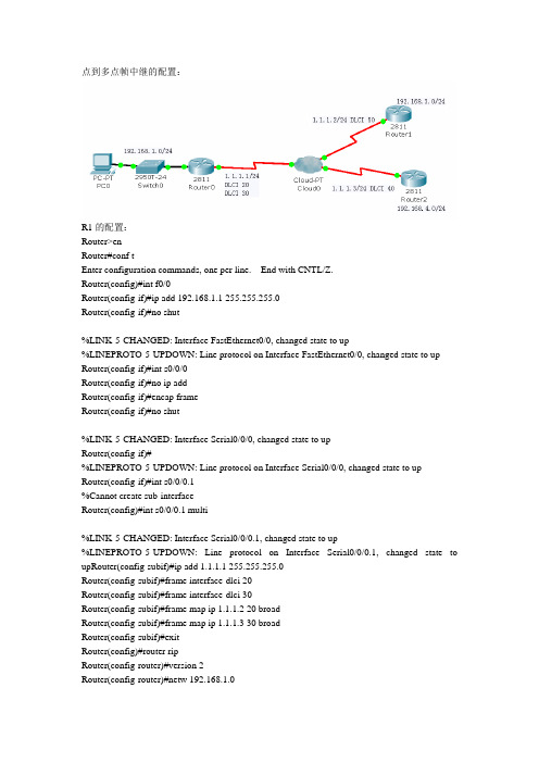
点到多点帧中继的配置:R1的配置:Router>enRouter#conf tEnter configuration commands, one per line. End with CNTL/Z.Router(config)#int f0/0Router(config-if)#ip add 192.168.1.1 255.255.255.0Router(config-if)#no shut%LINK-5-CHANGED: Interface FastEthernet0/0, changed state to up%LINEPROTO-5-UPDOWN: Line protocol on Interface FastEthernet0/0, changed state to up Router(config-if)#int s0/0/0Router(config-if)#no ip addRouter(config-if)#encap frameRouter(config-if)#no shut%LINK-5-CHANGED: Interface Serial0/0/0, changed state to upRouter(config-if)#%LINEPROTO-5-UPDOWN: Line protocol on Interface Serial0/0/0, changed state to upRouter(config-if)#int s0/0/0.1%Cannot create sub-interfaceRouter(config)#int s0/0/0.1 multi%LINK-5-CHANGED: Interface Serial0/0/0.1, changed state to up%LINEPROTO-5-UPDOWN: Line protocol on Interface Serial0/0/0.1, changed state to upRouter(config-subif)#ip add 1.1.1.1 255.255.255.0Router(config-subif)#frame interface-dlci 20Router(config-subif)#frame interface-dlci 30Router(config-subif)#frame map ip 1.1.1.2 20 broadRouter(config-subif)#frame map ip 1.1.1.3 30 broadRouter(config-subif)#exitRouter(config)#router ripRouter(config-router)#version 2Router(config-router)#netw 192.168.1.0Router(config-router)#netw 1.1.1.0Router(config-router)#end%SYS-5-CONFIG_I: Configured from console by consoleRouter#sh ip routeCodes: C - connected, S - static, I - IGRP, R - RIP, M - mobile, B - BGPD - EIGRP, EX - EIGRP external, O - OSPF, IA - OSPF inter areaN1 - OSPF NSSA external type 1, N2 - OSPF NSSA external type 2E1 - OSPF external type 1, E2 - OSPF external type 2, E - EGPi - IS-IS, L1 - IS-IS level-1, L2 - IS-IS level-2, ia - IS-IS inter area* - candidate default, U - per-user static route, o - ODRP - periodic downloaded static routeGateway of last resort is not set1.0.0.0/24 is subnetted, 1 subnetsC 1.1.1.0 is directly connected, Serial0/0/0.1C 192.168.1.0/24 is directly connected, FastEthernet0/0R 192.168.3.0/24 [120/1] via 1.1.1.2, 00:00:06, Serial0/0/0.1Router#sh ip routeCodes: C - connected, S - static, I - IGRP, R - RIP, M - mobile, B - BGPD - EIGRP, EX - EIGRP external, O - OSPF, IA - OSPF inter areaN1 - OSPF NSSA external type 1, N2 - OSPF NSSA external type 2E1 - OSPF external type 1, E2 - OSPF external type 2, E - EGPi - IS-IS, L1 - IS-IS level-1, L2 - IS-IS level-2, ia - IS-IS inter area* - candidate default, U - per-user static route, o - ODRP - periodic downloaded static routeGateway of last resort is not set1.0.0.0/24 is subnetted, 1 subnetsC 1.1.1.0 is directly connected, Serial0/0/0.1C 192.168.1.0/24 is directly connected, FastEthernet0/0R 192.168.3.0/24 [120/1] via 1.1.1.2, 00:00:19, Serial0/0/0.1Router#show ip routeCodes: C - connected, S - static, I - IGRP, R - RIP, M - mobile, B - BGPD - EIGRP, EX - EIGRP external, O - OSPF, IA - OSPF inter areaN1 - OSPF NSSA external type 1, N2 - OSPF NSSA external type 2E1 - OSPF external type 1, E2 - OSPF external type 2, E - EGPi - IS-IS, L1 - IS-IS level-1, L2 - IS-IS level-2, ia - IS-IS inter area* - candidate default, U - per-user static route, o - ODRP - periodic downloaded static routeGateway of last resort is not set1.0.0.0/24 is subnetted, 1 subnetsC 1.1.1.0 is directly connected, Serial0/0/0.1C 192.168.1.0/24 is directly connected, FastEthernet0/0R 192.168.3.0/24 [120/1] via 1.1.1.2, 00:00:11, Serial0/0/0.1R 192.168.4.0/24 [120/1] via 1.1.1.3, 00:00:05, Serial0/0/0.1Router#ping 192.168.3.1Type escape sequence to abort.Sending 5, 100-byte ICMP Echos to 192.168.3.1, timeout is 2 seconds:!!!!!R2的配置:Router>enRouter#conf tEnter configuration commands, one per line. End with CNTL/Z.Router(config)#int loop 0%LINK-5-CHANGED: Interface Loopback0, changed state to up%LINEPROTO-5-UPDOWN: Line protocol on Interface Loopback0, changed state to up Router(config-if)#ip add 192.168.3.1 255.255.255.0Router(config-if)#exitRouter(config)#int s0/0/0Router(config-if)#ip add 1.1.1.2 255.255.255.0Router(config-if)#no shut%LINK-5-CHANGED: Interface Serial0/0/0, changed state to upRouter(config-if)#encap frameRouter(config-if)#%LINEPROTO-5-UPDOWN: Line protocol on Interface Serial0/0/0, changed state to up Router(config-if)#frame map ip 1.1.1.1 50 broadRouter(config-if)#exitRouter(config)#router ripRouter(config-router)#version 2Router(config-router)#netw 192.168.3.0Router(config-router)#netw 1.1.1.0Router(config-router)#exitRouter(config)#exit%SYS-5-CONFIG_I: Configured from console by consoleRouter#R2的配置:Router>enRouter#conf tEnter configuration commands, one per line. End with CNTL/Z.Router(config)#int loop 2%LINK-5-CHANGED: Interface Loopback2, changed state to up%LINEPROTO-5-UPDOWN: Line protocol on Interface Loopback2, changed state to up Router(config-if)#ip add 192.168.4.1 255.255.255.0Router(config-if)#exitRouter(config)#int s0/0/0Router(config-if)#ip add 1.1.1.3 255.255.255.0Router(config-if)#no shut%LINK-5-CHANGED: Interface Serial0/0/0, changed state to upRouter(config-if)#encap frameRouter(config-if)#%LINEPROTO-5-UPDOWN: Line protocol on Interface Serial0/0/0, changed state to up Router(config-if)#frame map ip 1.1.1.1 40 broadRouter(config-if)#end%SYS-5-CONFIG_I: Configured from console by consoleRouter#conf tEnter configuration commands, one per line. End with CNTL/Z.Router(config)#router ripRouter(config-router)#version 2Router(config-router)#netw 192.168.4.0Router(config-router)#netw 1.1.1.0Router(config-router)#end%SYS-5-CONFIG_I: Configured from console by consoleRouter#writeBuilding configuration...[OK]Router#。
帧中继点到多点子接口
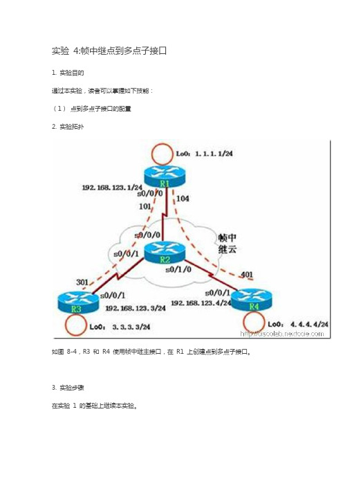
实验4:帧中继点到多点子接口1. 实验目的通过本实验,读者可以掌握如下技能:(1)点到多点子接口的配置2. 实验拓扑如图8-4,R3 和R4 使用帧中继主接口,在R1 上创建点到多点子接口。
3. 实验步骤在实验1 的基础上继续本实验。
(1) 对主接口进行配置R1(config)#interface serial0/0/0R1(config-if)#no ip address //注:主接口下不需要IP 地址R1(config-if)#encap frame-relay //注:封装帧中继R1(config-if)#no frame-relay inverse-arp //注:通常需要关闭主接口下的IARP R1(config-if)#no shutdown(2) 创建点到多点子接口R1(config)#int s0/0/0.1 multipoint //注:创建点到多点子接口R1(config-subif)#ip address 192.168.123.1 255.255.255.0R1(config-subif)#frame-relay map ip 192.168.123.3 103 broadcastR1(config-subif)#frame-relay map ip 192.168.123.4 104 broadcast//以上是配置帧中继映射(3) R1 上配置路由协议:R1(config)#router ripR1(config-router)#network 1.0.0.0R1(config-router)#network 192.168.123.0(4) R3、R4 完整的配置如下:R3(config)#interface serial 0/0/1R3(config-if)#ip address 192.168.123.3 255.255.255.0R3(config-if)#encapsulation frame-relayR3(config-if)#no frame-relay inverse-arpR3(config-if)#frame-relay map ip 192.168.123.1 301 broadcastR3(config-if)#no shutdownR3(config)#router ripR3(config-router)#network 3.0.0.0R3(config-router)#network 192.168.123.0R4(config)#interface serial 0/0/1R4(config-if)#ip address 192.168.123.4 255.255.255.0R4(config-if)#encapsulation frame-relayR4(config-if)#no frame-relay inverse-arpR4(config-if)#frame-relay map ip 192.168.123.1 401 broadcastR4(config-if)#no shutdownR4(config)#router ripR4(config-router)#network 4.0.0.0R4(config-router)#network 192.168.123.0【提示】可以使用“no interface s0/0/0.1”命令来删除子接口,然而需要重新启动路由器,该子接口才真正被删除。
点到点帧中继

点到点帧中继一.网络拓扑图二.实验要求1.根据网络拓扑图正确配置IP地址2.全网使用OSPF路由技术3.广域网链路之间使用点到点帧中继技术,LMI-TYPE为ANSI,根据拓扑图正确配置DLCI4.PC0 PING通PC1,PC0 PING 通PC2三.配置过程1.R1:Router>enaRouter#conf tEnter configuration commands, one per line. End with CNTL/Z.Router(config)#hos R1R1(config)#int f 0/0R1(config-if)#ip address 192.168.1.254 255.255.255.0R1(config-if)#no shutdownR1(config-if)#exiR1(config)#int s 2/0R1(config-if)#clo ra 64000 //封装时钟频率R1(config-if)#enc frame-relay ietf //封装帧中继协议,格式为ietfR1(config-if)#frame-relay lmi-type ansi //配置lmi-type为ansiR1(config-if)#ip ospf network point-to-point //配置OSPF传输为点到点模式R1(config-if)#no shutdownR1(config-if)#exiR1(config)#int s 2/0.1 point-to-point //进入S 2/0.1点到点子接口R1(config-subif)#ip address 10.1.1.1 255.255.255.0 //配置IP地址和子网掩码R1(config-subif)#frame-relay interface-dlci 20 //配置DLCIR1(config-subif)#no shutdownR1(config-subif)#ip ospf network point-to-pointR1(config-subif)#no shutdownR1(config-subif)#exiR1(config)#int s 2/0.2 point-to-pointR1(config-subif)#ip address 10.1.2.1 255.255.255.0R1(config-subif)#frame-relay interface-dlci 30R1(config-subif)#ip ospf network point-to-pointR1(config-subif)#no shutdownR1(config-subif)#exiR1(config)#router ospf 1R1(config-router)#network 10.1.1.0 0.0.0.255 ar 0R1(config-router)#network 10.1.2.0 0.0.0.255 ar 0R1(config-router)#network 192.168.1.0 0.0.0.255 ar 0R1(config-router)#exiR1(config)#do wrBuilding configuration...[OK]2.R2:Router>enaRouter#conf tEnter configuration commands, one per line. End with CNTL/Z.Router(config)#hos R2R2(config)#int f 0/0R2(config-if)#ip address 192.168.2.254 255.255.255.0R2(config-if)#no shutdownR2(config-if)#exiR2(config)#int s 2/0R2(config-if)#ip address 10.1.1.2 255.255.255.0 //配置IP地址和子网掩码R2(config-if)#clo ra 64000R2(config-if)#ip ospf network point-to-pointR2(config-if)#enc frame-relay ietf //封装帧中继R2(config-if)#frame-relay lmi-type ansi //配置lmi-typeR2(config-if)#frame-relay interface-dlci 21 //配置DLCIR2(config-if)#no shutdownR2(config-if)#exiR2(config)#router ospf 1R2(config-router)#network 10.1.1.0 0.0.0.255 ar 0R2(config-router)#network 192.168.2.0 0.0.0.255 ar 0R2(config-router)#exiR2(config)#do wrBuilding configuration...[OK]3.R3:Router>enaRouter#conf tEnter configuration commands, one per line. End with CNTL/Z.Router(config)#hos R3R3(config)#int f 0/0R3(config-if)#ip address 192.168.3.254 255.255.255.0R3(config-if)#no shutdownR3(config-if)#exiR3(config)#int s 2/0R3(config-if)#ip address 10.1.2.2 255.255.255.0 //配置IP地址和子网掩码R3(config-if)#clo ra 64000R3(config-if)#enc frame-relay ietf //封装帧中继R3(config-if)#frame-relay lmi-type ansi //配置lmi-typeR3(config-if)#frame-relay interface-dlci 31 //配置DLCIR3(config-if)#ip ospf network point-to-pointR3(config-if)#no shutdownR3(config-if)#exiR3(config)#router ospf 1R3(config-router)#network 10.1.2.0 0.0.0.255 ar 0R3(config-router)#network 192.168.3.0 0.0.0.255 ar 0R3(config-router)#exiR3(config)#do wrBuilding configuration...[OK]4.网络云四.配置文件1.R1:R1#sh runBuilding configuration...Current configuration : 1134 bytes!version 12.2no service timestamps log datetime msec no service timestamps debug datetime msec no service password-encryption!hostname R1!!!!!!!!!!!!!!!!!!interface FastEthernet0/0ip address 192.168.1.254 255.255.255.0 duplex autospeed auto!interface FastEthernet1/0no ip addressduplex autospeed autoshutdown!interface Serial2/0no ip addressencapsulation frame-relay ietf frame-relay lmi-type ansiip ospf network point-to-pointclock rate 64000!interface Serial2/0.1 point-to-pointip address 10.1.1.1 255.255.255.0 frame-relay interface-dlci 20clock rate 2000000!interface Serial2/0.2 point-to-pointip address 10.1.2.1 255.255.255.0 frame-relay interface-dlci 30clock rate 2000000!interface Serial3/0no ip addressclock rate 2000000shutdown!interface FastEthernet4/0no ip addressshutdown!interface FastEthernet5/0no ip addressshutdown!router ospf 1log-adjacency-changesnetwork 10.1.1.0 0.0.0.255 area 0 network 10.1.2.0 0.0.0.255 area 0 network 192.168.1.0 0.0.0.255 area 0 !ip classless!!!!!!!line con 0line vty 0 4login!!!End2.R2:R2#sh runBuilding configuration...Current configuration : 900 bytes!version 12.2no service timestamps log datetime msec no service timestamps debug datetime msec no service password-encryption!hostname R2!!!!!!!!!!!!!!!!!!interface FastEthernet0/0ip address 192.168.2.254 255.255.255.0 duplex autospeed auto!interface FastEthernet1/0no ip addressduplex autospeed autoshutdown!interface Serial2/0ip address 10.1.1.2 255.255.255.0 encapsulation frame-relay ietf frame-relay interface-dlci 21frame-relay lmi-type ansiip ospf network point-to-pointclock rate 64000!interface Serial3/0no ip addressclock rate 2000000shutdown!interface FastEthernet4/0no ip addressshutdown!interface FastEthernet5/0no ip addressshutdown!router ospf 1log-adjacency-changesnetwork 10.1.1.0 0.0.0.255 area 0 network 192.168.2.0 0.0.0.255 area 0 !ip classless!!!!!!!line con 0line vty 0 4login!!!End3.R3:R3(config)#do sh runBuilding configuration...Current configuration : 900 bytes!version 12.2no service timestamps log datetime msec no service timestamps debug datetime msec no service password-encryption!hostname R3!!!!!!!!!!!!!!!!!!interface FastEthernet0/0ip address 192.168.3.254 255.255.255.0 duplex autospeed auto!interface FastEthernet1/0no ip addressduplex autospeed autoshutdown!interface Serial2/0ip address 10.1.2.2 255.255.255.0 encapsulation frame-relay ietfframe-relay interface-dlci 31frame-relay lmi-type ansiip ospf network point-to-pointclock rate 64000!interface Serial3/0no ip addressclock rate 2000000shutdown!interface FastEthernet4/0no ip addressshutdown!interface FastEthernet5/0no ip addressshutdown!router ospf 1log-adjacency-changesnetwork 10.1.2.0 0.0.0.255 area 0 network 192.168.3.0 0.0.0.255 area 0 !ip classless!!!!!!!line con 0line vty 0 4login!!!End五.测试结果从PC0 PING 通PC1 PC2:。
帧中继配置(点到点)
帧中继是ISP提供的一种广域网服务,是一种网络与数据终端设备(DTE)接口标准,多用于公司总部与分支机构互连。
帧中继的主要特点是:使用光纤作为传输介质,因此误码率极低,能实现近似无差错传输,减少了进行差错校验的开销,提高了网络的吞吐量;帧中继是一种宽带分组交换,使用复用技术时,其传输速率可高达44.6Mbps。
但是,帧中继不适合于传输诸如话音、电视等实时信息,它仅限于传输数据。
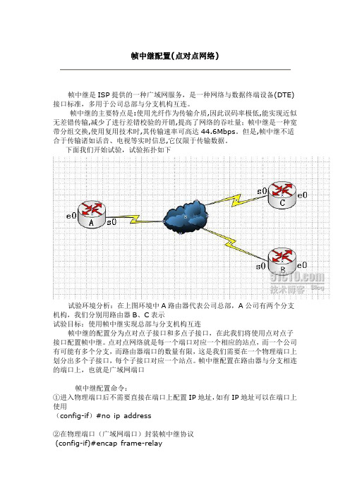
下面我们开始试验,试验拓扑如下试验环境分析:在上图环境中A路由器代表公司总部,A公司有两个分支机构,我们分别用路由器B、C表示试验目标:使用帧中继实现总部与分支机构互连帧中继的配置分为点对点子接口和多点子接口,在此我们将使用点对点子接口配置帧中继。
点对点网络就是每一个端口对应一个相应的站点,而一个公司有可能有多个分支,而路由器端口的数量有限,这是我们需要在一个物理端口上划分出多个子接口,每个子接口对应一个站点。
帧中继配置在路由器与分支相连的端口上,也就是广域网端口帧中继配置命令:①进入物理端口后不需要直接在端口上配置IP地址,如有IP地址可以在端口上使用(config-if)#no ip address②在物理端口(广域网端口)封装帧中继协议(config-if)#encap frame-relay③激活物理端口(config-if)#no shutdown④在物理端口上建立子接口,并指定接口类型(config-if)#interface 子接口point-to-point⑤给子接口配置IP地址和子网掩码(config-subif)#ip address IP地址子网掩码⑥给子接口配置DLCI值(config-subif)#frame-relay interface-dlci DLCI值⑦给子接口配置端口速率(config-sibif)#bandwidth 带宽DLCI值IP地址规划A:e0---192.168.10.1 B:e0---192.168.20.1 C:e0---192.168.30.1 s0.1--202.110.100.1 s0---202.110.100.2 s0---202.110.10 1.2s0.2--202.110.101.1一、配置A路由器A(config)#interface e0 进入局域网端口A(config-if)#ip address 192.168.10.1 255.255.255.0配置局域网I P和掩码A(config-if)#no shutdown激活局域网端口A(config-if)# interface s0 进入广域网端口A(config-if)#no ip address 删除广域网端口的IPA(config-if)#no shutdown 激活广域网A(config-if)#encap frame-relay封装帧中继协议A(config-if)#interface s0.1 point-to-point 在物理端口上建立子接口S0.1,指定端口类型A(config-subif)#ip address 202.110.100.1 255.255.255.0给子接口配置IP和掩码A(config-subif)#frame-relay interface-dlci 102 给S0.1子接口封装DLCIA(config-subif)#bandwidth 64给S0.1子接口配置A(config-subif)#interface s0.2 point-to-point 建立子接口S0.2,并指定子接口类型A(config-subif)#ip address 202.110.101.1 255.255.255.0 给子接口S0.2配置IP和掩码A(config-subif)#frame-relay interface-dlci 103给S0.2子接口封装DLCIA(config-subif)#bandwidth 64 给S0.2子接口配置端口速率A(config-subif)#exit 退出子接口A(config)#router eigrp 100 配置路由,协议为EIGRPA(config-router)#net 192.168.10.0A(config-router)#net 202.110.100.0A(config-router)#net 202.110.101.0二、配置B路由器B路由器上有两个端口,一个是局域网端口E0,一个是广域网端口S0,S0为连接A路由器的S0.1端口,不需要配置子接口,只需要配置IP地址然后封装帧中继协议即可B(config)#int e0B(config-if)#ip address 192.168.20.1 255.255.255.0B(config-if)#no shutdownB(config-if)#int s0B(config-if)#ip address 202.110.100.2 255.255.255.0B(config-if)#encap frame-relayB(config-if)#frame-relay interface-dlci 201B(config-if)#bandwidth 64B(config-if)#no shutB(config-if)#exitB(config)#router eigrp 100B(config-router)#net 192.168.20.0B(config-router)#net 202.110.100.0三、配置路由器CC路由器有两个端口,E0为局域网端口。
帧中继的配置

帧中继的配置一.帧中继帧中继协议是一个第二层协议,即数据链路层协议,它工作在OSI参考模型的物理层和数据链路层。
帧中继提供面向连接的数据链路层通讯,由于其可靠的性能,因此目前成为一种非常重要的广域网技术。
在学习帧中继的过程中,以下的几个术语及与其相关的技术是必须要重点掌握的内容:●虚电路(Virtual circuit):为保证两个DTE设备(如路由器)之间的双向通信而创建的逻辑链路称为虚电路(VC),帧中继用虚电路来提供端点之间的连接,用DLCI来标识;●永久虚电路(Permanent VC-PVC):由服务提供商预先设置,在需要经常通过帧中继网络进行数据传送的DTE设备之间建立的永久逻辑连接,称为永久虚电路(PVC);●交换虚电路(Switched VC-SVC):在只需要通过帧中继网络进行零星数据传送的DTE 设备之间建立的临时的逻辑连接,称为交换虚电路(SVC),它是动态设置的虚电路;●DLCI:数据链路连接标识符(Data-Link Connection Identifier),是帧中继帧头的地址字段中用来区分VC的10bits标识,该标识具有本地意义,只涉及到本地路由器和所连帧中继交换机之间的那一部分,只是路由器和帧中继交换机之间表示VC的数字,因此,远端设备可以用与本地设备相同或完全不同的DLCI表示同样一条逻辑连接,两端的DLCI互不相干。
帧中继交换机通过在一对路由器之间映射DLCI来创建虚电路;●本地访问速率(Local Access Rate):指连接到帧中继云团的连接(本地回路)的时钟速度(端口速度),是数据流入或流出网络的速率;●LMI:本地管理接口(Local Management Interface),是用户设备(DTE)和帧中继交换机(DCE)之间的信令标准,它负责管理设备之间的连接并维护设备之间的连接状态;●CIR:承诺信息速率(Committed Information Rate):申请帧中继服务时服务提供商(ISP)承诺提供的有保证的速率,CIR是在正常条件下帧中继网络保证为用户传送数据所提供的最大平均数据速率;●Inverse ARP:反向地址解析协议(Inverse Address Resolution Protocol),动态地把远端设备的网络层地址与本地DLCI相关联的方法,使本地路由器能自动发现与一个VC相关联的远端设备的网络层地址;●帧中继映射:作为第二层的协议,帧中继协议必须有一个与第三层协议之间建立关联的手段,才能用它来实现网络层的通信,帧中继映射即实现这样的功能,它把网络层地址和DLCI之间进行映射。
基于Cisco Packet Tracer仿真环境的帧中继点到点模式实验设计

基于Cisco Packet Tracer仿真环境的帧中继点到点模式实验设计一、实验目的本实验通过在Cisco Packet Tracer仿真环境中搭建帧中继网络,实际模拟帧中继网络中的点到点模式,以达到以下几个目的:1. 理解帧中继网络的基本工作原理;2. 掌握帧中继网络的配置方法;3. 了解帧中继网络的调试技术;4. 掌握帧中继网络的故障排除方法。
二、实验环境1. 软件环境:Cisco Packet Tracer;2. 硬件环境:模拟器;3. 实验设备:路由器、交换机。
三、实验内容1. 网络拓扑设计在Cisco Packet Tracer中创建一个新的项目,然后按照以下网络拓扑图搭建网络结构:```+------------------+| RouterA || Serial 0/0 |+--------|---------+| DCE+------+------+ +------+| Sw1 | | Sw2 |+------+------+ +------+| DTE+------+|+------+| RouterB || Serial 0/0 |+----------------+```2. 路由器配置我们需要配置两台路由器的基本信息,包括主机名、密码等。
然后配置两台路由器的串口接口,将它们连接到交换机上。
配置思路如下:- 配置路由器A的Serial 0/0接口,配置帧中继接口并配置DCE;- 配置路由器B的Serial 0/0接口,配置帧中继接口并配置DTE。
3. 交换机配置在交换机上,我们只需要简单的配置即可。
配置思路如下:- 在Sw1上,将连接路由器A的接口设置为Trunk模式;- 在Sw2上,将连接路由器B的接口设置为Trunk模式。
4. 网络地址分配为了方便管理,我们需要为路由器A和B的接口分配IP地址。
我们还需要配置帧中继接口的数据链路层参数。
5. 测试帧中继连接在完成上述配置之后,我们需要测试帧中继连接是否能够正常工作。
实验九 帧中继协议的配置

实验九帧中继协议的配置一、配置帧中继DTE实验拓扑图【实验步骤】1、路由器R0上的配置如下:二、配置帧中继DCE实验拓扑图【实验步骤】1、路由器R0上的配置如下:三、配置帧中继点对点子接口实验拓扑图【实验步骤】1、路由器R0上的配置如下:Router>enRouter#conf tRouter(config)#no ip domain-lookup //取消名称解析Router(config)#int f0/0Router(config-if)#ip add 172.16.1.1 255.255.255.0 //配置ip地址Router(config-if)#no shutRouter(config-if)#int s0/1/0Router(config-if)#encapsulation frame-relay //对串口serial0/1/0进行frame-relay封装Router(config-if)#no shutRouter(config-if)#int s0/1/0.1 point-to-point //进入串口的子接口配置模式Router(config-subif)#ip add 192.168.3.2 255.255.255.0Router(config-subif)#description link router2 dlci 41Router(config-subif)#frame-relay interface-dlci 20 //配置DLCIRouter(config-subif)#int s0/1/0.2 point-to-pointRouter(config-subif)#ip add 192.168.2.2 255.255.255.0Router(config-subif)#description link router1 dlci 31Router(config-subif)#frame-relay interface-dlci 21 //配置DLCIRouter(config-subif)#exitRouter(config)#exitRouter#conf tRouter(config)#router eigrp 100 //在路由器上启用EIGRP路由协议Router(config-router)#network 172.16.0.0 //通告与自己直接想连的网段Router(config-router)#network 192.168.3.0Router(config-router)#network 192.168.2.0Router(config-router)#exitRouter(config)#exitRouter#copy running-config startup-conifg2、路由器R1上的配置如下:Router>enRouter#conf tRouter(config)#no ip domain-lookup //取消名称解析Router(config)#int f0/0Router(config-if)#ip add 172.17.1.1 255.255.255.0 //配置ip地址Router(config-if)#no shutRouter(config-if)#int s0/1/0Router(config-if)#encapsulation frame-relay //对串口serial0/1/0进行frame-relay封装Router(config-if)#no shutRouter(config-if)#int s0/1/0.1 point-to-point //进入串口的子接口配置模式Router(config-subif)#ip add 192.168.1.2 255.255.255.0Router(config-subif)#description link to router2 dlci40Router(config-subif)#frame-relay interface-dlci 30 //配置DLCIRouter(config-subif)#int s0/1/0.2 point-to-pointRouter(config-subif)#ip add 192.168.2.1 255.255.255.0Router(config-subif)#description link to router0 dlci21Router(config-subif)#frame-relay interface-dlci 31 //配置DLCIRouter(config-subif)#exitRouter(config)#router eigrp 100 //在路由器上启用EIGRP路由协议Router(config-router)#network 192.168.1.0 //通告与自己直接想连的网段Router(config-router)#network 192.168.2.0Router(config-router)#network 172.17.0.0Router(config-router)#exitRouter(config)#exitRouter#copy running-config startup-config3、路由器R2上的配置如下:Router>en //进入特权配置模式Router#conf t //进入全局配置模式Router(config)#no ip domain-lookup //取消名称解析Router(config)#hostname Router2 //配置路由器的名字Router2(config)#int f0/0 //进入接口配置模式Router2(config-if)#ip add 172.18.1.1 255.255.255.0 //配置ip地址Router2(config-if)#no shut //激活端口Router2(config-if)#int s0/1/0Router2(config-if)#encapsulation frame-relay //对串口serial0/1/0进行frame-relay封装Router2(config-if)#no shutRouter2(config-if)#int s0/1/0.1 point-to-point //进入串口的子接口配置模式Router2(config-subif)#ip add 192.168.1.1 255.255.255.0 //为子接口配置IP地址Router2(config-subif)#description Link Router1 DLCI 30 //为子接口添加描述Router2(config-subif)#frame-relay interface-dlci 40 //配置DLCIRouter2(config)#int s0/1/0Router2(config-if)#int s0/1/0.2 point-to-pointRouter2(config-subif)#ip add 192.168.3.1 255.255.255.0Router2(config-subif)#description link to Router0 DLCI 20Router2(config-subif)#frame-relay interface-dlci 41Router2(config)#router eigrp 100 //在路由器上启用EIGRP路由协议Router2(config-router)#network 172.18.0.0 //通告与自己直接想连的网段Router2(config-router)#network 192.168.3.0Router2(config-router)#network 192.168.1.0Router2(config-router)#exitRouter2#copy running-config startup-config //保存配置4、配置Cloud0如下:【检测实验结果】用ping命令测试各pc机之间的连通性。
基于Cisco Packet Tracer仿真环境的帧中继点到点模式实验设计
基于Cisco Packet Tracer仿真环境的帧中继点到点模式实验设计一、实验目的1. 了解帧中继技术的基本概念和原理。
2. 掌握Cisco Packet Tracer仿真环境下帧中继点到点模式的配置和实现。
3. 学习如何在实验中进行帧中继点到点模式的故障排除和维护。
二、实验环境和工具三、实验内容和步骤1. 搭建实验网络在Cisco Packet Tracer中搭建一个简单的帧中继点到点模式的网络拓扑,包括两台路由器和一台交换机。
路由器1通过串口连接帧中继交换机,路由器2也通过串口连接帧中继交换机。
确保路由器1和路由器2之间可以通过帧中继交换机进行通信。
2. 配置帧中继交换机a. 在帧中继交换机上配置时钟同步和物理接口。
b. 配置数据链路连接标识符(DLCI)。
c. 启用帧中继接口并设置带宽。
d. 配置路由器到交换机的连接。
3. 配置路由器1和路由器24. 测试帧中继点到点模式配置完成后,进行测试,通过路由器1和路由器2之间的点到点链路进行数据通信测试,验证帧中继点到点模式的正常工作。
5. 故障排除和维护在测试过程中,如果出现问题,需要进行故障排除。
通过检查配置和日志信息等方式,找出故障原因,并进行调整和修复。
同时学习如何维护帧中继网络,确保网络的正常运行。
四、预期结果通过本实验,学生将能够了解帧中继技术的基本原理和工作方式,掌握帧中继点到点模式的配置和实现方法,并学会如何在实验中进行故障排除和维护。
通过实际操作的经验积累,加深对帧中继技术的理解和掌握。
五、实验总结。
实验 3:帧中继环境下的点到点模式
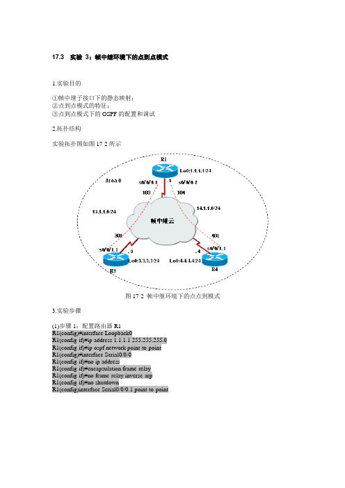
17.3 实验3:帧中继环境下的点到点模式1.实验目的①帧中继子接口下的静态映射;②点到点模式的特征;③点到点模式下的OSPF的配置和调试2.拓扑结构实验拓扑图如图17-2所示图17-2 帧中继环境下的点点到模式3.实验步骤(1)步骤1:配置路由器R1R1(config)#interface Loopback0R1(config-if)#ip address 1.1.1.1 255.255.255.0R1(config-if)#ip ospf network point-to-pointR1(config)#interface Serial0/0/0R1(config-if)#no ip addressR1(config-if)#encapsulation frame-relayR1(config-if)#no frame-relay inverse-arpR1(config-if)#no shutdownR1(config)interface Serial0/0/0.1 point-to-pointR1(config-subif)#ip address 13.1.1.1 255.255.255.0 R1(config-subif)#frame-relay interface-dlci 103R1(config)#interface Serial0/0/0.2 point-to-pointR1(config-subif)#ip address 14.1.1.1 255.255.255.0 R1(config-subif)#frame-relay interface-dlci 104R1(config)#router ospf 1R1(config-router)#router-id 1.1.1.1R1(config-router)#network 1.1.1.0 0.0.0.255 area 0 R1(config-router)#network 13.1.1.0 0.0.0.255 area 0 R1(config-router)#network 14.1.1.0 0.0.0.255 area 0 (2)步骤2:配置路由器R3R3(config)#interface Serial0/0/1R3(config-if)#no ip addressR3(config-if)#encapsulation frame-relayR3(config-if)#no franme-relay inverse-arpR3(config-if)#no shutdownR3(config)#interface Serial0/0/1.1 point-to-pointR3(config-subif)#ip address 13.1.1.3 255.255.255.0 R3(config-subif)#frame-relay interface-dlci 301R3(config)#router ospf 1R3(config-router)#router-id 3.3.3.3R3(config-router)#network 3.3.3.0 0.0.0.255 area 0 R3(config-router)#network 134.1.1.0 0.0.0.255 area 0 (3)步骤3:配置路由器R4R4(config)#interface Serial0/0/1R4(config-if)#no ip addressR4(config-if)#encapsulation frame-relayR4(config-if)#no franme-relay inverse-arpR4(config-if)#no shutdownR4(config)#interface Serial0/0/1.1 point-to-pointR4(config-subif)#ip address 14.1.1.4 255.255.255.0 R4(config-subif)#frame-relay interface-dlci 401R4(config)#router ospf 1R4(config-router)#router-id 4.4.4.4R4(config-router)#network 4.4.4.0 0.0.0.255 area 0 R4(config-router)#network 14.1.1.0 0.0.0.255 area 04.实验调试(1)show ip ospf interfaceR1#show ip ospf interface s0/0/0.1Serial0/0/0.1 is up,line protocol is upInternet Address 13.1.1.1/24,Area 0Process ID 1,Router ID 1.1.1.1,Network Type POINT_TO_POINT,Cost;64Transmit Delay is 1 sec,State POINT_TO_POINTTimer intervals configured,Hello 10,Dead 40,Wait 40,Retransmit 5 //POINT_TO_POINT模式下,Hello周期为10 soob-resync timeout 40Hello due in 00;00;09Index 2/2,flood queue length 0Next 0x0(0)/0x0(0)Last flood scan length is 1,maximum is 1Last flood time is 0 masec,maximum is 4 msecNeighbor Count is 1,Adjacent neighbor count is 1Adjacent with neighbor 3.3.3.3Suppress hello for 0 neighbor(s)(2)show ip ospf neighbor detailR1#show ip ospf neighbor detailNeighbor 4.4.4.4,interface address 14.1.1.4In the area 0 via interface Serial0/0/0.2Neighbor priority is 0,State is FULL,6 state changesDR is 0.0.0.0 BDR is 0.0.0.0Options is 0x52LLS Options is 0x1(LR)Dead timer due in 00;00;34Neighbor isup for 00;07;21Index 2/2,retransmission queue length 0,number of retransmission 1Fist 0x0(0)/0x0(0) Next 0x0(0)/0x0(0)Last retransmission scan length is 1,maximum is 1Last retransmission scan time is 0 msec,maximum is 0 msecNeighbor 3.3.3.3,interface address 13.1.1.3In the area 0 via interface Serial0/0/0.1Neighbor priority is 0,State is FULL,6 state changesDR is 0.0.0.0 BDR is 0.0.0.0Options is 0x52LLS Options is 0x1(LR)Dead timer due in 00;00;32Neighbor isup for 00;08;51Index 1/1,retransmission queue length 0,number of retransmission 1Fist 0x0(0)/0x0(0) Next 0x0(0)/0x0(0)Last retransmission scan length is 1,maximum is 1Last retransmission scan time is 0 msec,maximum is 0 msec以上输出表明路由器R1通过两个子接口分别与路由器R3和R4建立邻接关系【技术要点】①点倒点模式中的DR和BDR是”0.0.0.0”;②在点到点模式下,每个子接口需要配置不同的网络;③点到点模式下,Hello周期为10 s。
使用点对点子接口的方式配置帧中继

中心配置Central#configure terminalEnter configuration commands, one per line. End with CNTL/Z.Central(config)#interface Serial0Central(config-if)#description Frame-Relay host circuitCentral(config-if)#no ip addressCentral(config-if)#encapsulation frame-relayCentral(config-if)#exitCentral(config)#interface Serial0.1 point-to-pointCentral(config-subif)#description PVC to first branch - DLCI 101Central(config-subif)#ip address 192.168.1.5 255.255.255.252Central(config-subif)#frame-relay interface-dlci 101Central(config-fr-dlci)#exitCentral(config-subif)#exitCentral(config)#interface Serial0.2 point-to-pointCentral(config-subif)#description PVC to second branch - DLCI 102Central(config-subif)#ip address 192.168.1.9 255.255.255.252Central(config-subif)#frame-relay interface-dlci 102Central(config-fr-dlci)#exitCentral(config-subif)#exitCentral(config)#endCentral#边缘配置Branch1#configure terminalEnter configuration commands, one per line. End with CNTL/Z.Branch1(config)#interface Serial0Branch1(config-if)#description Frame-Relay circuitBranch1(config-if)#no ip addressBranch1(config-if)#encapsulation frame-relayBranch1(config-if)#exitBranch1(config)#interface Serial0.1 point-to-pointBranch1(config-subif)#description PVC to Central host - DLCI 50Branch1(config-subif)#ip address 192.168.1.6 255.255.255.252Branch1(config-subif)#frame-relay interface-dlci 50Branch1(config-fr-dlci)#exitBranch1(config-if)#exitBranch1(config)#endBranch1#注释点对点子接口方式应该是最简单的一种帧中继配置方式了。
Point-to-point帧中继 与mutipoint帧中继的配置
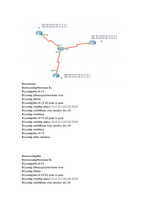
Router#conf tRouter(config)#hostname R1R1(config)#int s0/1/0R1(config-if)#encapsulation frame-relayR1(config-if)#exitR1(config)#int s0/1/0.102 point-to-pointR1(config-subif)#ip address 12.12.12.1 255.255.255.0 R1(config-subif)#frame-relay interface-dlci 102R1(config-subif)#exitR1(config)#int s0/1/0.103 point-to-pointR1(config-subif)#ip address 13.13.13.1 255.255.255.0 R1(config-subif)#frame-relay interface-dlci 103R1(config-subif)#exitR1(config)#int s0/1/0R1(config-if)#no shutdownRouter(config)#hoRouter(config)#hostname R2R2(config)#int s0/3/0R2(config-if)#encapsulation frame-relayR2(config-if)#exitR2(config)#int s0/3/0.201 point-to-pointR2(config-subif)#ip address 12.12.12.2 255.255.255.0 R2(config-subif)#frame-relay interface-dlci 201R2(config-subif)#exitR2(config)#int s0/3/0.203 point-to-pointR2(config-subif)#ip address 14.14.14.1 255.255.255.0 R2(config-subif)#frame-relay interface-dlci 203R2(config-subif)#exitR2(config)#int s0/3/0R2(config-if)#no shutdownRouter>enRouter#conf tRouter(config)#hostname R3R3(config)#int s0/3/0R3(config-if)#encapsulation frame-relayR3(config-if)#exitR3(config)#int s0/3/0.301 point-to-pointR3(config-subif)#ip address 13.13.13.2 255.255.255.0 R3(config-subif)#frame-relay interface-dlci 301R3(config-subif)#exitR3(config)#int s0/3/0.302 point-to-pointR3(config-subif)#ip address 14.14.14.2 255.255.255.0 R3(config-subif)#frame-relay interface-dlci 302R3(config-subif)#exitR3(config)#int s0/3/0R3(config-if)#no shutdownMutipointRouter(config)#hostname R1R1(config)#int s0/3/0R1(config-if)#encapsulation frame-relayR1(config-if)#exitR1(config)#int s0/3/0.1 multipointR1(config-subif)#ip address 12.12.12.1 255.255.255.0R1(config-subif)#frame-relay map ip 12.12.12.2 102 broadcast R1(config-subif)#frame-relay map ip 12.12.12.3 103 broadcast R1(config-subif)#exitR1(config)#int s0/3/0R1(config-if)#no shutdownR2(config)#int s0/3/0.1 multipointR2(config-subif)#ip address 12.12.12.2 255.255.255.0R2(config-subif)#frame-relay map ip 12.12.12.1 201 broadcast R2(config-subif)#frame-relay map ip 12.12.12.3 203 broadcastR3(config)#int s0/3/0.1 multipointR3(config-subif)#ip address 12.12.12.3 255.255.255.0R3(config-subif)#frame-relay map ip 12.12.12.1 301 broadcast R3(config-subif)#frame-relay map ip 12.12.12.2 302 broadcast。
基于Cisco Packet Tracer仿真环境的帧中继点到点模式实验设计

基于Cisco Packet Tracer仿真环境的帧中继点到点模式实验设计1. 引言1.1 介绍实验的背景帧中继是一种常用的网络传输技术,它通过将帧从一个物理网络传输到另一个物理网络来实现数据传输。
帧中继点到点模式则是在帧中继网络中建立点到点的连接,实现一对一的通信。
在网络通信领域中,帧中继点到点模式的实验是非常重要的,可以帮助学生深入了解帧中继技术的工作原理以及实际应用。
在实际网络环境中,帧中继点到点模式广泛应用于企业内部网络中,作为不同局域网之间的桥梁,实现数据的快速传输和通信的连通。
掌握帧中继点到点模式的配置和数据传输过程对于网络工程师来说至关重要。
通过基于Cisco Packet Tracer仿真环境进行帧中继点到点模式实验设计,可以帮助学生在虚拟的网络环境中进行实践操作,提升他们的实际操作能力和解决问题的能力。
实验可以帮助学生深入理解帧中继技术的工作原理和配置方法,为他们今后的工作和研究打下坚实的基础。
1.2 阐述实验的目的实验的目的是通过基于Cisco Packet Tracer仿真环境搭建帧中继点到点模式实验,并进行数据传输实验,从而深入了解帧中继技术的原理和实际应用。
通过配置和调试实验环境,掌握帧中继的配置方法和技巧。
通过实验结果的分析和总结,评估帧中继点到点模式在网络通信中的性能表现和优缺点。
通过探讨实验中遇到的问题及解决方案,提高网络故障排除能力和问题处理能力。
通过本次实验,目的是加深对帧中继技术的理解和应用,提高网络通信技术水平和实践能力,为今后在网络通信领域的进一步研究和应用奠定基础。
通过本次实验的开展,可以更好地理解和掌握帧中继技术的实际应用,为今后进一步的研究和探索提供实践基础和理论支持。
1.3 说明实验的重要性1. 实践能力培养:通过搭建帧中继点到点模式的实验环境,可以让学生有更多的机会动手实践,提高他们的操作技能和解决问题的能力。
这对于培养学生的实践能力非常重要。
基于Cisco Packet Tracer仿真环境的帧中继点到点模式实验设计

基于Cisco Packet Tracer仿真环境的帧中继点到点模式实验设计一、实验目的本实验旨在通过Cisco Packet Tracer仿真环境,设计帧中继点到点模式的网络实验,以帮助学生掌握帧中继技术的基本原理和配置方法。
通过该实验,学生将能够了解帧中继的工作原理、学会配置帧中继链路的基本参数以及了解帧中继的状态监测等内容。
二、实验环境1. 工具准备:Cisco Packet Tracer仿真软件2. 实验设备:两台路由器(Router)和两台交换机(Switch)三、实验内容1. 配置帧中继链路的基本参数2. 配置帧中继链路的状态监测3. 测试帧中继链路的连通性四、实验步骤1. 搭建实验网络拓扑在Cisco Packet Tracer中新建一个实验项目,然后依次拖拽两台路由器和两台交换机到画布中,将它们连接成如下拓扑结构:```Router1 ------ Switch1 ------ Switch2 ------ Router2```在此拓扑结构中,Router1和Router2分别代表两个不同的帧中继网络,Switch1和Switch2分别代表两个帧中继的交换机。
2. 配置帧中继链路的基本参数a) 配置Router1在Router1的命令行界面中,输入以下命令配置帧中继链路的基本参数:```Router1(config)# interface serial 0/0/0Router1(config-if)# encapsulation frame-relayRouter1(config-if)# frame-relay interface-dlci 102Router1(config-if)# ip address 192.168.1.1 255.255.255.0Router1(config-if)# no shutdown```上述命令中,配置了Router1的序列接口0/0/0为帧中继接口,并为其配置了帧中继的DLCI(Data Link Connection Identifier)号为102,IP地址为192.168.1.1。
- 1、下载文档前请自行甄别文档内容的完整性,平台不提供额外的编辑、内容补充、找答案等附加服务。
- 2、"仅部分预览"的文档,不可在线预览部分如存在完整性等问题,可反馈申请退款(可完整预览的文档不适用该条件!)。
- 3、如文档侵犯您的权益,请联系客服反馈,我们会尽快为您处理(人工客服工作时间:9:00-18:30)。
实验拓扑:
帧中继云配置:
一、IP地址规划
R1:
S0/3/0.2 192.168.1.253 /30
S0/3/0.3 192.168.3.254 /30
F0/0 192.168.1.14 /28
PC1 192.168.1.2 /28
PC2 192.168.1.3 /28
R2:
S0/3/0.1 192.168.1.254 /30
S0/3/0.3 192.168.2.253 /30
F0/0 192.168.2.14 /28
PC3 192.168.2.3 /28
PC4 192.168.2.4 /28
R3:
S0/3/0.1 192.168.3.253/30
S0/3/0.2 192.168.2.254/30
F0/0 192.168.3.14/28
PC5 192.168.3.5/28
PC6 192.168.3.6/28
R5:
F0/0 192.168.2.5/30
二、设备命令配置
R1配置:
R1(config)#int f0/0
R1(config-if)#ip add 192.168.1.14 255.255.255.240 //f0/0配置IP :192.168.1.14/28
R1(config-if)#no shut
R1(config)#int s0/3/0
R1(config-if)#no ip add //因为创建子接口所以不要IP
R1(config-if)#encapsulation frame-relay //封装为帧中继
R1(config-if)#no shut //开启接口
R1(config)#int s0/3/0.2 point-to-point //进入点到点帧中继子接口2(R2)
R1(config-subif)#frame-relay interface-dlci 112 //设置dlci(只有在点到点帧中继子接口才可以用命令:frame-relay interface-dlci)
R1(config-subif)#ip add 192.168.1.253 255.255.255.240 //设置IP。
注意掩码
R1(config)#int s0/3/0.2 point-to-point //进入点到点帧中继子接口2(R3)
R1(config-subif)#frame-relay interface-dlci 113 //设置dlci
R1(config-subif)#ip add 192.168.3.254 255.255.255.240 //设置IP
R1(config)#router eigrp 10 //进入设置eigrp 区域10 注意:不同区域不能通信R1(config)#network 192.168.1.0 //通告直连网段
R1(config)#network 192.168.1.252 //通告直连网段
R1(config)#network 192.168.3.252 //通告直连网段eigrp支持不连续子网、VLSM
R3配置
R3(config)#int f0/0
R3(config-if)#ip add 192.168.3.14 255.255.255.240
R3(config-if)#no shut
R3(config)#int s0/3/0
R3(config-if)#no ip add
R3(config-if)#encapsulation frame-relay
R3(config-if)#no shut
R3(config)#int s0/3/0.1 point-to-point
R3(config-subif)#frame-relay interface-dlci 311
R3(config-subif)#ip add 192.168.3.253 255.255.255.240
R3(config)#int s0/3/0.2 point-to-point
R3(config-subif)#frame-relay interface-dlci 312
R3(config-subif)#ip add 192.168.2.254 255.255.255.240
R3(config)#router eigrp 10
R3(config)#network 192.168.3.0
R3(config)#network 192.168.3.252
R3(config)#network 192.168.2.252
R2配置
1、帧中继和eigrep与R1/R3一样配置就好
自己试试
2、R2-设置静态NAT:
R2(config)#ip nat inside source static 192.168.2.5 192.168.2.253 //配置静态NAT R2(config)#int s0/3/0.3 //通过数据出去选择out
R2(config-subif)#ip nat outside
R2(config)#int f0/0
R2(config-if)#ip nat inside //注意接口选择,通过数据进入选择in
在R5上配置telnet
Router(config)#line vty 0 4 //选择线路
Router(config-line)#password cisco //设置密码
Router(config-line)#login //启用密码,不打login远程无效果Router(config-line)#exi
通过静态NAT我们可以直接telnet 192.168.2.253来远程控制R5
现实中:通过申请ISP的IP地址来配置静态NAT,以便远程访问公司内网
刚刚学习CCNA
有志同道合的可以加我QQ
一起学习。
