RDS-CL-05中文资料
CL2005
CL2005系列异步通讯屏控制系统工程手册使用CL2005系列通讯屏控制系统前请先仔细阅读本手册。
一、指标Ⅰ型卡:控制范围:1024列×128行(单色)或1024列×64行(双色)扫描场频:110HZ总存储量:4M位带温度输入、湿度输入支持1/16扫描工作模式提供遥控选择播放画面的专用版Ⅱ型卡:控制范围:1024列×256行(单色)或1024列×128行(双色)扫描场频:110Hz总存储量:8M位带温度输入、湿度输入8级亮度手动调节、自动调节(需外接传感器)支持1/16扫描、1/8扫描、1/4扫描、1/2扫描和静态工作模式提供遥控选择播放画面的专用版Ⅳ型卡:控制范围:2048列×128行(单色)或2048列×64行(双色)其它指标同Ⅱ型卡。
二、外型尺寸Ⅰ型卡外型和尺寸如下图所示:Ⅱ型、Ⅳ卡外型和尺寸如下图所示:三、电源控制卡使用5±5%V的直流电源。
电源接线柱旁标明了极性。
四、指示灯及外部电源控制标有‘LP’的是电源指示灯,接通控制卡的电源后该灯亮;标有‘LR’的是通讯接收指示灯,有数据发送给控制卡该灯亮;标有‘LT’的是通讯发送指示灯,当控制卡有数据发出时该灯亮;标有‘LS’的是外部电源开关指示灯,当外部电源被打开时该灯亮。
标有‘JSW’的插座是外部电源控制口,提供3V20mA左右的控制电流用于控制固态继电器。
五、通讯接口使用DB9的9针插座作为通讯口。
通讯波特率选择请参看(七、2)当U6插Max232(或兼容芯片),U7和U8位置不插芯片时,控制卡工作在RS232通讯方式:通讯口的Pin2为数据接收,一般接计算机9针串口的Pin3;通讯口的Pin3为数据发送,一般接计算机9针串口的Pin2;通讯口的Pin5是地线,一般接计算机9针串口的Pin5。
当U6不插芯片,U7和U8插入Max485(或兼容芯片)时,控制卡工作在RS422通讯模式:通讯口的Pin1是T-,接计算机串口RS232/422转换器的R-;通讯口的Pin2是T+,接计算机串口RS232/422转换器的R+;通讯口的Pin3是R+,接计算机串口RS232/422转换器的T+;通讯口的Pin4是R-,接计算机串口RS232/422转换器的T-;通讯口的Pin5是GND,接计算机串口RS232/422转换器的GNDRS422模式下,若将通讯口的Pin1和Pin4短路,将Pin2和Pin3短路,则控制卡工作在RS485模式。
朴素联系器(India)私有有限公司产品说明书:PT 5-HF-12 DC-ST保护插头
Extract from the onlinecatalogPT 5-HF-12 DC-ST Order No.: 2838775Protective plug PT with HF protective circuit for 4 signal wires. Nominal voltage: 12 V DChttp://Please note that the data givenhere has been taken from theonline catalog. For comprehensiveinformation and data, please referto the user documentation. TheGeneral Terms and Conditions ofUse apply to Internet downloads. Technical dataGeneralHousing material PAInflammability class acc. to UL 94V0Color blackStandards for air and creepage distances DIN VDE 0110-1IEC 60664-1: 1992-10Surge voltage category IIIPollution degree2Total surge current (8/20) µs20 kAAmbient temperature (operation)-40 °C ... 85 °CMounting type On base elementDesign DIN rail module, two-section, divisibleNumber of positions5Degree of protection IP20Direction of action Line-Line & Line-Signal Ground/Shield & optional Signal Ground/Shield-Earth GroundFrom SW rev. 1.00Arrester can be tested with CHECKMASTER fromsoftware version:Width17.70 mmHeight52.00 mmLength45.00 mmPitch unit 1 Div.Protective circuitIEC category C1C2C3D1VDE requirement class C1C2C3D1Nominal voltage U N12 V DCMax. operating voltage U max14 V DCArrester rated voltage U C14 V DC9.8 V ACArrester rated voltage U C (Core-Core)14 V DC9.8 V ACArrester rated voltage U C (Core-Earth)14 V DC (with PT 2x2-BE)Nominal current I N450 mA (45°C)Operating effective current I C at U C≤ 5 µADischarge current to PE at U C≤ 5 µA (with PT 2x2-BE)≤ 1 µA (with PT 2x2+F-BE)Nominal discharge surge current In (8/20) µs10 kA(Core-Core)10 kANominal discharge surge current I n (8/20) µs(Core-Earth)Total surge current (8/20) µs20 kA10 kAMax. discharge surge current Imax (8/20) µsmaximum (Core-Core)10 kAMax. discharge surge current Imax (8/20) µsmaximum (Core-Earth)Nominal pulse current Ian (10/1000) µs (Core-67 ACore)Lightning test current (10/350) µs, peak value l imp 2.5 kA≤ 25 VOutput voltage limitation at 1 kV/µs (Core-Core)spikeOutput voltage limitation at 1 kV/µs (Core-Earth)≤ 25 Vspike≤ 700 V (with PT 2x2+F-BE)≤ 25 VOutput voltage limitation at 1 kV/µs (Core-Core)static≤ 25 VOutput voltage limitation at 1 kV/µs (Core-Earth)static≤ 40 V (with PT 2x2+F-BE)Output voltage limitation at 1 kV/µs (Core-GND)staticResidual voltage at I n, (conductor-conductor)≤ 25 VResidual voltage at In, (conductor-ground)≤ 40 VResidual voltage at In, (conductor-GND)≤ 25 V (with PT 2x2-BE)≤ 25 VResidual voltage with Ian (10/1000)µs (conductor-conductor)Residual voltage with Ian (10/1000)µs (conductor-≤ 25 VGND)Response time tA (Core-Core)≤ 500 nsResponse time tA (Core-Earth)≤ 500 nsInput attenuation aE, sym.0.2 dB (≤ 5 MHz)Cut-off frequency fg (3 dB), sym. in 100 OhmTyp. 70 MHzsystemCapacity (Core-Core)Typ. 30 pFResistance in series 2.2 ΩMax. required back-up fuse500 mA (e.g. T in acc. with IEC 127-2/III) Connection dataType of connection Screw connection (in connection with the base element)Connection type IN PLUGTRAB plug-in systemConnection type OUT PLUGTRAB plug-in systemConductor cross section stranded min.0.2 mm²Conductor cross section stranded max. 2.5 mm²Conductor cross section solid min.0.2 mm²Conductor cross section solid max. 4 mm²Conductor cross section AWG/kcmil min.24Conductor cross section AWG/kcmil max12Connection, protective circuitStandards/regulations IEC 61643-21Certificates / ApprovalsCertification GOST, UL ListedCertification Ex:CUL-EX LIS, UL-EX LISAccessoriesItem Designation DescriptionMarking0811228X-PEN 0,35Marker pen without ink cartridge, for manual labeling of markers,labeling extremely wipe-proof, line thickness 0.35 mm0811228X-PEN 0,35Marker pen without ink cartridge, for manual labeling of markers,labeling extremely wipe-proof, line thickness 0.35 mm0811228X-PEN 0,35Marker pen without ink cartridge, for manual labeling of markers,labeling extremely wipe-proof, line thickness 0.35 mm0814717ZBF 15:SO/CMS Zack strip, flat, 10-section, divisible, special printing, markingaccording to customer requirements0808671ZBF 5,LGS:FORTL.ZAHLEN Zack strip, flat, printed horizontally: 10-section, with the numbers,1-10, 11-20 etc. up to 991-1000, color: White0810821ZBF 5,LGS:GERADE ZAHLEN Zack marker strip, flat, printed horizontally: 10-section, with evennumbers, printed with the numbers: 2-20, 22-40, etc. up to 82-1000810863ZBF 5,LGS:UNGERADEZAHLEN Zack strip, flat, printed horizontally: 10-section, with odd numbers, printed with the numbers: 1-19, 21-39 etc. up to 81-99Dimensioned drawingThe figure shows the complete module consisting of a baseelement and connectorCircuit diagramApproval logo (Ex area)。
PRMA1C05中文资料
-
108
1010
-
Ω
-
1.5
2
-
1.2
2
pF
3
4
-
3
4
pF
1400
-
-
2000
-
- VDC/Peak AC
I/O
1400
-
-
5600
-
- VDC/Peak AC
TOP
-
1.2
1.75
-
1.2
1.75
ms
TREL
-
1
1.50
-
1
1.50
ms
TA
-40
-
+105 -40
-
+105
°C
TO
-38
-
+75
-38
Carry Current PRMA/PRME/DSS7 PRMA Form C MSS2/MSS7 MVS2/MVS7
Switching Frequency PRMA/PRME/DSS7 PRMA Form C MSS2/MSS7/MVS2/MVS7
Contact Resistance PRMA/PRME/DSS7 PRMA Form C MSS2/MSS7/MVS2/MVS7
11±1ms, 1/2 Sine Wave
(1) Refer to life graphs
SYMBOL
MSS2 Molded 8 Pin All position Wetted contacts
MIN TYP MAX
MSS7 Molded 4 Pin All position Wetted contacts
英维克冷水列间空调XR030C及冷量分配单元CDU180机组用户手册--腾讯版
英飞凌 ICE5QRxx80BG 第五代准谐振集成电源IC 数据表
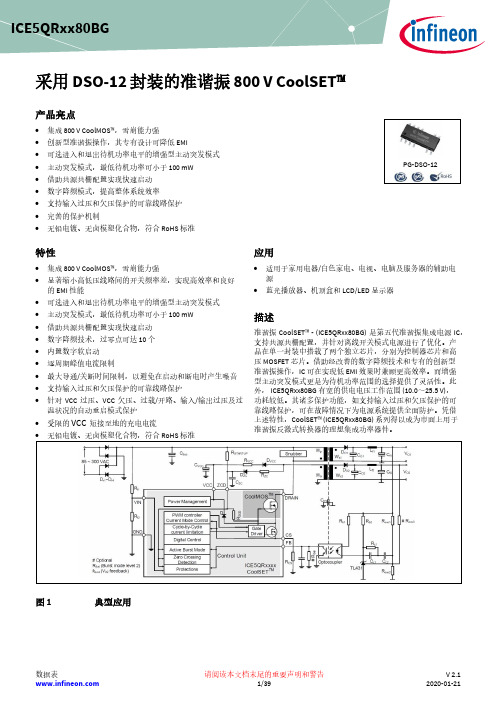
采用 DSO-12 封装的准谐振 800 V CoolSET ™产品亮点• 集成 800 V CoolMOS ™,雪崩能力强 • 创新型准谐振操作,其专有设计可降低 EMI• 可选进入和退出待机功率电平的增强型主动突发模式 • 主动突发模式,最低待机功率可小于 100 mW • 借助共源共栅配置实现快速启动 • 数字降频模式,提高整体系统效率 • 支持输入过压和欠压保护的可靠线路保护 • 完善的保护机制•无铅电镀、无卤模塑化合物,符合 RoHS 标准特性• 集成 800 V CoolMOS ™,雪崩能力强• 显著缩小高低压线路间的开关频率差,实现高效率和良好的 EMI 性能• 可选进入和退出待机功率电平的增强型主动突发模式 • 主动突发模式,最低待机功率可小于 100 mW • 借助共源共栅配置实现快速启动 • 数字降频技术,过零点可达 10 个 • 内置数字软启动 • 逐周期峰值电流限制• 最大导通/关断时间限制,以避免在启动和断电时产生噪音 • 支持输入过压和欠压保护的可靠线路保护•针对 VCC 过压、VCC 欠压、过载/开路、输入/输出过压及过温状况的自动重启模式保护• 受限的 VCC 短接至地的充电电流• 无铅电镀、无卤模塑化合物,符合 RoHS 标准应用• 适用于家用电器/白色家电、电视、电脑及服务器的辅助电源• 蓝光播放器、机顶盒和 LCD/LED 显示器描述准谐振 CoolSET ™ - (ICE5QRxx80BG) 是第五代准谐振集成电源 IC ,支持共源共栅配置,并针对离线开关模式电源进行了优化。
产品在单一封装中搭载了两个独立芯片,分别为控制器芯片和高压 MOSFET 芯片。
借助经改善的数字降频技术和专有的创新型准谐振操作,IC 可在实现低 EMI 效果时兼顾更高效率。
而增强型主动突发模式更是为待机功率范围的选择提供了灵活性。
此外, ICE5QRxx80BG 有宽的供电电压工作范围 (10.0~25.5 V), 功耗较低。
人民电器 RDS5系列电动机保护断路器 使用说明书

目 录RDS5-32(X)系列电动机保护断路器RDS5-80系列电动机保护断路器2 18…………………………………………………………………………SERIESR D S5-32(X)系列电动机保护断路器符合标准:G B/T14048.4 GB/T 14048.21、用途与适用范围RDS5-32(X )系列电动机保护断路器,适用于交流电压至690V 额定频率50Hz /60Hz ,额定电流从0.1到32A 的电路中,作为三相鼠笼型异步电动机的过载、断相、短路保护及不频繁的起动控制之用,也可用作配电线路保护和不频繁的负载转换,还可作隔离器使用。
产品符合:GB /T 14048.2、GB /T 14048.4、IEC60947-2 、IEC60947-4-1标准。
2、正常工作和安装条件2.1 安装地点的海拔一般不超过2000m ;2.2 周围空气温度下限一般不低于-5℃,上限一般不高于+40℃;2.3 空气相对湿度在温度为+40℃时相对湿度不大于50%,在最湿月的月平均最低温度在25℃时月平均最大相对湿度不大于90%;2.4 周围环境污染等级为3级;2.5 起动器的安装类别为Ⅱ、Ⅲ(负载水平等级及配电水平等级)2.6 安装面与垂直面倾斜度不大于±5°2.7 额定工作制:不间断工作制。
,RD S 5 - 32 (X) /无:按钮式 X :旋钮式壳架等级额定电流设计序号电动机保护断路器企业代号脱扣器整定电流(A)3、型号及含义1.合闸按钮(旋钮)2.指示件12挂锁孔图14、工作原理及结构特点RDS5-32(X )电动机保护断路器是将隔离器、断路器、热继电器功能集于一身的一体化电器,具有隔离、过载、温度补偿、断相、短路保护等功能。
RDS5-32(X )结构:通过热元件接入主回路内,它流过电动机的电流。
当电动机过载时,双金属片加热到动作温度使保护断路器动作。
当电动机断相时,由于断相一相双金属片冷却回复,通过差动机构的放大作用,使保护断路器动作。
Emaux SSC Mini盐水氯化器快速用户指南说明书
Clorador salinoSSC MiniGuía rápida de usuarioApreciado cliente:Gracias por elegir este sistema de cloración salina SSC Mini.En la siguiente página, al pulsar sobre cada sección encontrará la información principal sobre este equipo.Permítanos invitarle a conocer con más detalle toda nuestra gama de productos.Si pulsa en el logo Emaux más abajo, un enlace URL le llevará a nuestra página web.Esperamos que le guste!Índice1.Advertencias de seguridad2.Características principales3.Esquema de instalación4.Guía de montaje5.Operación del equipo6.Mantenimiento7.Diagnóstico de averías1.Advertencias de seguridadAntes de instalar este producto, lea y siga las siguientes notas e instrucciones:•Toda la instalación, procedimientos de operación y mantenimiento debe ser realizado por un profesional cualificado, o bien por una persona que ha sido instruida adecuadamente.•Desconecte siempre la unidad de control cuando realice cualquier labor sobre el equipo.•Asegúrese cablear el equipo de tal modo que el clorador de sal funcione cuando la bomba de filtración esté funcionando.•Después del mantenimiento periódico, verifique que el sistema no tiene fugas.•Si los componentes eléctricos del aparato se mojan, desenchúfelo inmediatamente.•El aumento de la cantidad de sal en la piscina de agua aumenta la probabilidad de sufrir corrosión u otros procesos de deterioro dentro del equipo de su piscina.•Puede generarse cloro gas si el clorador se activa cuando la bomba de filtración no funciona correctamente.•Para la limpieza química, use el equipo de seguridad adecuado y consulte las instrucciones del producto químico sobre cómo manejar y desechar dichos productos.2.Características principales Datos técnicos del equipoModeloSSC Mini 230V, 50 –60Hz Caudal máximo25 m 3/h Producción máx.20 g/h Presión máxima 2.5 barEntrada/Salida 50 mm 1 ½’’ BSP 60 mm 2’’ BSPSalinidad3000 ppm Temperatura10 to 45 ºC Vol. piscina máx.90 m 3Balance químico recomendado AlimentaciónLeyenda1 Bomba de filtraci6n2 Filtro3 Bomba de calor*4 V. antiretorno5 Sonda de pH*Opcional...2l6 Bomba dosificadora7 Tanque de pH -8 lnyección pH -9 Unidad de control SSCMini10 Celcula electrolitica SSCMini11 By-pass de celula...1t693 741 5// 8lA p iscina3.Esquema de instalaciónA d esagüe De p iscinaIr a Índice Ir a guía de instalaciónPara una instalación correcta, siga lasrecomendaciones que se enumeran a continuación:4.Guía de instalaciónUnidad de control•Elija un área bien ventilada, respetando siempre la longitud del cable de la celda, así como las características principales del equipo SSC Mini.•La unidad de control debe mantenerse alejada de la luz solar, de cualquier fuente de calor o de cualquier almacenamiento de productos químicos.•Fije la unidad de control verticalmente a 1,5metros sobre el nivel del suelo y al menos 3metros de la piscina.•Conecte la bomba de manera que la unidad de control funcione siempre y cuando el sistema SSC lo haga, como se comenta en 1. Advertencias de seguridad .•Vigile con la parte posterior del equipo: puede alcanzar temperaturas elevadas.•Si está instalando este sistema en una piscina de yeso, espere al menos 1 mes después de haber construido la piscina para poner en marcha la unidad. De esta manera el yeso podrá curar adecuadamente.•Se recomienda instalar un ánodo de sacrificio y unirlo, así como los otros componentes metálicos de la piscina, a la tierra principal, para así evitar corrosión galvánica.Célula electrolítica•La célula debe colocarse horizontalmente, cerca del retorno de la piscina.•Para optimizar la eficacia del cloro, la celda debe ser canalizada como se muestra en el 3.Esquema de instalación.•Debe instalarse respetando el sentido de flujo de en la carcasa de la celda.•Se recomienda un by-pass en la celdaelectrolítica.•Si hay un sistema de calefacción o UV, es muy recomendable instalar una válvula de retención después de estos componentes.•Antes de conectar o manipular los conectoreseléctricos de la celda, asegúrese de que la fuente de alimentación no esté conectada.•Conecte el cable de acuerdo con la númeración que aparecen en los conectores, como se ve en las imagen inferior.•Antes de probar el sistema hidráulico, espere 24 horas después de haber pegado la tubería para asegurar el secado de la cola.Conexión de la célula a5.Operación del equipoPara lograr la instalación correcta, siga las recomendaciones que se detallan a continuación:•Añada la sal antes de encender el sistema. Elclorador SSC Mini debe estar apagado. Esperehasta que la sal se disuelva haciendo funcionar la bomba y colocando la válvula de 6 vías en modo de recirculación.•Agregue la sal en distintas veces y lugares parafacilitar su disolución.•Los principales parámetros químicos debenmantenerse en torno a los siguientes valoresmostrados en la sección 2.Característicasprincipales•No mantener es e balance químic o puede:•Dañar y reducir la vida útil de la célula.•Inactivar la eficacia del cloro.•Deteriorar los componentes de la piscina.•El balance de agua y un buen ambiente deoperación deben estar asegurados para garantizar una piscina segura.•En caso de calor extremo o muchos bañistas,aumente la potencia de salida del sistema SSC oagregar cloro sólido / líquido.Panel de controlLEDs1.Baja vida de célula:deterioro de la célula.2.Sin flujo:no hay agua en la célula.3.Alarma general: Ver 7.Solución de problemas4.Modo stand-by: La unidad no produce acorde con el horario establecido.5.Operación normal: La unidad estáproduciendo acorde con el horario establecido de filtración.6.Supercloración: La unidad estáproduciendo durante24 horas sin interrupción.9.Potencia: Cada LED representsa6 min de producción. Ejemplo: 3 LEDs equivale a 18 min, 4 LEDs equivale a 24 min, etc.Botones7.Supercloración:produce cloro24 horas seguidas.8.Control de potencia: Alarga(+) o acorta(-) el tiempo de producción.6.Mantenimiento•En función de la dureza del agua, la célula debe ser revisada periódicamente para evitar un aumento de incrustación.•Como se dijo en 5. Operación del equipo, es obligatorio mantener el balance químico en el rango especificado. De no hacerlo, la garantía de la célula podría quedar anulada.•Para limpiar la celda, proceda de la siguiente manera:1.Desconecta la unidad de control.2.Retire la célula de su carcasa después dehaber drenado la tubería donde está.3.Enjuague con agua fresca la célula paraeliminar cualquier residuo u otra partícula.4.Siguiendo las instrucciones de seguridadmencionadas en 1. Advertencias deseguridad, mezcle 1 parte de ácidomuriático con 4 de agua dulce en un balde.Siempre agregue ácido al agua,nunca alrevés.5.Introduzca la célula en esta solución. Repitadespués de haber enjuagado con aguafresca. No frote con un cepillo de metal.6.Luego, enjuague la celda con agua frescay vuelva a ensamblarla.7.Antes de volver a encender el equipo, dejeque la célula se llene de agua.•Una dureza del agua muy alta puede causar incrustación excesiva. Para evitarlo, drene un poco de agua y vuelva a llenar con agua descalcificada.•Al lavar y vaciar el filtro, desconecte la unidad de control para no producir cloro sin que pueda ser evacuado del sistemaPROBLEMA POSIBLE CAUSA POSIBLE SOLUCIÓNBaja producción de cloroUnidad de controlno conectadaRevise la alimentacióneléctrica y el cablehacia la célulaInsuficienteproducción de cloroIncremente las horasde funcionamientoFusible fundido Desconécte el equipoy cambie el fusible pH alto Ajústelo entre 7.0 y 7.6Incrustamiento encélulaLea la sección6.Mantenimiento Falta de agua en lacélulaRevise la instalaciónhidráulicaBajo nivel de salAñada sal acorde lasección5.Operacióndel equipo Alto nivel deestabilizanteDrene el agua y rellenecon agua fresca Baja temperatura deaguaEncienda elcalentador7.Solución de problemasPROBLEMA POSSIBLE CAUSA POSSIBLE SOLUCIÓNFalta de caudal Válvulas cerradas Revise la posición delas válvulasLa bomba notrabajacorrectamenteRevise elfuncionamiento de labombaFiltro sucio Limpie el filtroAire en el sistema Revise entradas deaire y nivel de aguaIncorrecto voltaje deentrada Bajo nivel de sal y/o incrustación en célula Error en cable/célula Indicadores de displayAlto nivel de sal Temperatura del agua fuera de rango Revise los parámetros eléctricos de alimentación Compruebe el estado del cable o célula Revise el nivel de sal y/o el estado de la célula Desagüe un poco la piscina y añada agua fresca Ajuste la temperatura acorde los rangos de 2.Características principales POSIBLE SOLUCIÓN SIGNIFICADO。
RDS-CL-08资料

Installation Instructions for the ISSUE 3Sensing and ControlWARNING PERSONAL INJURY• DO NOT USE this product in applications where product failure could result in personal injury or death.• Improper installation of this device can cause personal injury. STRICTLY FOLLOW the instructions below.MECHANICAL SPECIFICATIONSOperating Temperature-40 °C to +85 °C (-40 °F to +185 °F)Shock 500 g, halfsine 1.6 msec (IEC68-2-27)Vibration Sinusoidal 10-2000 Hz, 20 G, (IEC68-2-6) 30minutes each axis for temperatures-40 °C, +25 °C, +85 °C Mounting Torque Bracket mounting bolts: 33,9 N m (35 ft lb) Sensor clamp mounting bolts: 9,5 N m (7 ft lb)MOUNTING INSTRUCTIONS (see Figures 1-3) 1. Select sensor mounting location.2. Grind all overflow from top and sides of rail.3. Drill two holes exactly 84,1 (3.31 in) from top of rail and 351,8 mm (13.85 in) apart. Distance H must be 42 mm to 48 mm (1.65 in to 1.89 in).4. Mount bracket using two 3/8 in bracket mounting bolts, two 3/8 in lockwashers, and two 3/8 in hex nuts. Torque to 33,9 N m (35 ft lb).5. To install one sensor (Single Mount): Positionsensor between the two holes marked 1 on top ofthe bracket so that distance X is 32,0 mm (1.26 in). Place two 5/16 in sensor clamp mounting bolts, threaded end up, through the two holes marked 1. Place two sensor clamp mounting brackets, two 5/16 in lockwashers, and two 5/16 incastlenuts on the bolts and torque to 9,5 N m (7 ft lb). Install two 3/64 in cotter pins in holes provided and secure. 6. To install two sensors (Dual Mount): Position thesensors above the two outside holes marked 2 on top of the bracket so that distance X is 32,0 mm (1.26 in). Place three 5/16 in sensor clamp mounting bolts, threaded ends up, through the three holes marked 2. Place three sensor clampmounting brackets, three 5/16 in lockwashers, and three 5/16 in castlenuts on the bolts and torque to 9,5 N m (7 ft lb). Install three 3/64 in cotter pins inholes and secure.7. As rail wears, use mounting slots on bracket to readjust sensor assembly.RDS-CL-08 Railwheel Sensor Bracket ISSUE 3 PK 80101Sensing and Control Honeywell Inc.11 West Spring Street Freeport, Illinois 61032/sensingWARRANTY/REMEDYHoneywell warrants goods of its manufacture as being free of defective materials and faultyworkmanship. Contact your local sales office forwarranty information. If warranted goods are returned to Honeywell during the period of coverage,Honeywell will repair or replace without charge those items it finds defective. The foregoing is Buyer’s sole remedy and is in lieu of all other warranties, expressed or implied, including those of merchantability and fitness for a particular purpose.Specifications may change without notice. The information we supply is believed to be accurate and reliable as of this printing. However, we assume no responsibility for its use.While we provide application assistancepersonally, through our literature and the Honeywell web site, it is up to the customer to determine the suitability of the product in the application.For application assistance, current specifications, or name of the nearest Authorized Distributor, contact a nearby sales office. Or call: 1-800-537-6945 USA 1-800-737-3360 Canada 1-815-235-6847 International FAX1-815-235-6545 USA INTERNET/sensing info.sc@。
CL5 说明书

CL 5操作手册标识号 021-002-296版本 01版本 01,2005 年 4 月发布,适用于软件版本 XX.04.XX目录1一般信息............................................1-11.1给 CL 5 供电..........................................1-21.2开关仪器................................................1-41.3CL 5 的主要功能...................................1-4CL 5 高精度测厚仪基本仪器.....................1-5仪器选件..................................................1-61.4本手册内容............................................1-6 2了解小键盘、菜单系统和显示屏幕........................2-12.1小键盘功能............................................2-22.2解释显示屏幕........................................2-22.3使用配置显示屏幕...............................2-10 3设置 CL 5...........................................3-13.1连接探头并加载设置文件....................3-33.2配置仪器................................................3-63.2.1设置仪器增益................................3-83.2.2设置更新率...................................3-83.2.3设置标称厚度................................3-83.3仪器校准................................................3-93.4设置最大和最小厚度警报....................3-93.5创建和删除自定义设置文件...............3-113.6锁定和解锁仪器设置...........................3-14 4测量厚度............................................4-14.1选择显示视图........................................4-24.2正常测量模式(无A扫描)...............4-34.3最小扫描和最大扫描测量模式............4-64.4差值/缩减率测量模式...........................4-8Krautkramer CL 5 版本 01,2005 年 4 月0-1目录4.5厚度 + A 扫描测量模式(可选).......4-104.6速度测量模式(可选)........................4-8 5使用可选数据记录器........................5-15.1创建新数据记录器文件........................5-25.2调用和删除已存储数据记录器文件....5-45.3将厚度测量值和速度测量值记录到数据记录器文件中........................................5-55.3.1将 A 扫描结果记录到数据记录器文件中................................5-65.3.2浏览数据记录器文件.....................5-65.4打印报告................................................5-6 6I/O 特性...............................................6-16.1将厚度读数传送到外部设备................6-26.2设置通信速度(波特率)和连接到 PC..........................................6-46.3远程命令................................................6-4 7规格7.1仪器规格................................................7-27.2A扫描选件特性....................................7-57.3速度测量选件特性................................7-57.4速度测量选件特性连接和使用数字千分尺................................7-67.5CL 5 探头/传感器规格..........................7-6 8维护仪器保养.........................................................8-20-2版本 01,2005 年 4 月Krautkramer CL 5目录9附录....................................................9-19.1重置操作软件........................................9-29.2升级操作软件........................................9-29.3EMC 文档...............................................9-39.4制造商/维修地址...................................9-510索引..................................................10-1Krautkramer CL 5 版本 01,2005 年 4 月0-3重要声明重要声明Krautkramer 超声波测厚仪的任何用户都必须阅读并了解下列信息。
酒店对电气要求

一般而言,一、二星级酒店是规模比拟小的建筑,在照明电气设计方面,与其它公共建筑相像而没有特别的地方,三星级及以上的酒店,除平房式建筑和度假村外,多为高层建筑,除具有高层民用建筑共同特点外,还有其特别性。
参照明电气专业而言,大致有如下的一些要求:I、根本要求:一、供电电源和负荷估算:1.酒店的电源进线宜有两路高压,且来自不同的高压配电站。
2.为了保证重要负荷供电,酒店必需设柴油发电机组作为应急备用电源,且当市电失电后,发电机必需马上启动并在15s内能投入正常带负荷运行,机组应与电力系统联锁,不得与其并列运行,当市电复原时,机组应自动退出工作并延时停机。
柴油发电机组的容量应满意以下重要负荷的用电要求:消防负荷及保安负荷、生活水泵、全部或局部客梯、厨房动力、餐厅1/4-1/3照明、锅炉房、客房照明(至少应有一个灯)、电话交换机、有线电视机房、计算机房、冷库(总仓)等。
二、照明系统:1.以下场所的照光明度必需是可调光的和可改变的(详细方案可由灯光设计师拟定):全部的餐厅、酒吧、会议室、宴会厅、大堂、多功能厅、包房。
2.煤气房、日用油箱间及危急品仓库的灯具开关,应采纳防爆型的产品。
3.酒店的公共大厅、门厅、休息厅、大楼梯厅、公共走道、客房层走道、户外庭院、消防楼梯及前室、疏散通道、地下层走道等非封闭场所的照明限制开关,可设在效劳台(总效劳台或相应层效劳台)等处集中限制或采纳BA限制。
三、播送音响系统:⒈走道、电梯内、大堂、餐厅、咖啡厅、公共卫生间、酒吧、包房、员工餐厅、更衣室、效劳间、各后台区域以及其他公共场所都必需设背景音乐播送,且应能分区域限制音量。
⒉多功能大厅等场所宜设独立式扩声系统。
⒊客房内应设有可收听不少于4套节目的播送接收设备:2套音乐、2套当地的播送节目(FM)。
播送节目可设在电视频道上,通过酒店内部的电视线路传送,或者采纳专用的播送传输线路。
⒋有线播送系统宜兼作火灾应急播送,此时应按火灾应急播送的要求确定系统。
电路板级别控制器 CL 型号说明书

1Mounting Ordering no. Ordering no.Ordering no. Supply: 24 VAC/DC Supply: 115 VAC Supply: 230 VAC11-p circular plug CLP2ES1BM24 CLP2ES1B115CLP2ES1B230Conductive Sensors2-point Basic Level Controller Type CL with Teach-in• Conductive level controller• Teach-in of sensitivity – operating resistance from 3.5K Ωto 50 K Ω• For filling or emptying applications • Low-voltage AC electrodes• Easy installation with 11 pin circular plug • Rated operational voltage:24 VAC/DC, 115 VAC or 230 VAC • Output 8A/250 VAC SPDT relay• LED indication for: Calibration, faulty operation and relay status• Possibility of serial connectionProduct De s crip t ionsensitivity is adjustable by means of the teach-in function. µ-Processor based level controller.Max./min. control of charging/discharging of liquids. TheType SelectionSpecifications2Connection cable2 or3 conductor PVC cable,normally screened. Cable length: max. 100 m. The resistance between the cores and the ground must be at least 50k. Normally, it is re c ommended to use a screened cable between probe and controller, e.g.where the cable is placed in parallel to the load cables (mains). The screen has to be connected to pin 7 (refer-ence).Teach-in:Make sure that the refe rence electrode and one of the other electrodes are in con-tact with the liquid –approxi m ately 1 cm. Press the “teach” pushbutton at the front of the controller for approximately 2 seconds,until the green LED turns OFF . The controller will now auto-adjust itself ac c ord i ng to the res istance of the measuring liquid. If theresistance of the liquid is outside the maximum range handled by the controller,the green LED will flash quickly for a period of 2 seconds, indicating a wrong teach-in.Function settingThe controller works perdefaultas discharge. Connect pin 7 to pin 8 for charge.CascadeIf more than 2 levels are required, up to 7 amplifiers can be cascaded, as shown in the example below.Connect pin 9 of the master controller to ground and pin 11 of the master controller to pin 11 of the next controllers, the slave con-trollers (see drawing). Pin 9of the slave controllers must be left open!The connections must bemade by screened cable to achieve optimal operation,e.g. in cable pits or trays where the cable is close topower cables. Connect the screen to pin 7, and be sure that the distance between two systems is max 3m.Fill the tank with the liquid tobe measured and teach inthe master controller. If the teach in is performed cor-rectly, the green power LED of the slave controller(s) will switch off and indicate:ready for teach in.Teach in the slave con-trollers one by one, until all the green powerLED’s are on again. The system is now in run-mode.Example 1The diagram shows the level control connected as max. and min. con-trol. The re l ay react to the low alternating cur-rent created when the elec-trodes are in contact with the liquid. The reference (Ref) must be connected to the container or if the container consists of a non-conductive mater i al,to an additional electrode.(To be connected to pin 7). (In the diagram this electrode is shown by the dotted line)..Mode of OperationCLP2ES1BM24ChargingDischargingTime3Operating ScheduleSituation Teach-inFailure indicationThe following schedule provides an overview of the setup and failure situationsCondition Fill the tank with the liquid to be measured until thesecond longest electrode is immersed approx. 1cmThe Green lamp isflashing fast for approx. 2seconds after a teach-in operationAction Press the Teach button in front of the controller for approx. 2 seconds until the green control lamp turn off continuously. Release the teach buttonControl the electrode for short-cut connections.Control that the resistance of the measured liquid is within the specified rangeGreen Control lampTeach button Green lampTeach button Green lampCLP2ES1BM24Wiring DiagramDimension DrawingsAccessoriesDelivery Contents• 11 pole corcular socket ZVD11• Mounting rackSM13• Amplifier• Packaging: Carton box • Manual。
LUCD05FU 产品数据表特性说明书

LUCD05FUProduct datasheetCharacteristicsLUCD05FUAdvanced control unit, TeSys U, 1.25-5A, 3P motors, protection & diagnostic, class 20, coil 110-240V AC/DCMainRange of product TeSys U Range TeSys Product name TeSys U Device short name LUCDProduct or component type Advanced control unit Device application Motor control Motor protectionProduct specific application Basic protection and advanced functions, communication Main function availableManual resetProtection against phase failure and phase imbalance Earth fault protectionProtection against overload and short-circuit Product compatibilityPower base LUB12Power base LUB32Power base LUB38Power base LUB120Power base LUB320Power base LUB380Reversing contactor breaker LU2B12FU Reversing contactor breaker LU2B32FU Reversing contactor breaker LU2B38FU [Ue] rated operational voltage 690 V AC Network frequency 40...60 HzLoad type3-phase motor - cooling: self-cooled Utilisation categoryAC-44AC-41AC-43Motor power kW1.5 kW at 400...440 V AC 50/60 Hz2.2 kW at 500 V AC 50/60 Hz 3 kW at 690 V AC 50/60 Hz Rated motor current adjustment range1.25…5 Ai s c l a i m e r : T h i s d o c u m e n t a t i o n i s n o t i n t e n d e d a s a s u b s t i t u t e f o r a n d i s n o t t o b e u s e d f o r d e t e r m i n i n g s u i t a b i l i t y o r r e l i a b i l i t y o f t h e s e p r o d u c t s f o r s p e c i f i c u s e r a p p l i c a t i o n sThermal overload class Class 20 - frequency limit: 40…60 Hz - temperature compensation: -25…70 °C conforming to IEC60947-6-2Class 20 - frequency limit: 40…60 Hz - temperature compensation: -25…70 °C conforming to UL 508 Tripping threshold14.2 x Ir +/- 20 %Phase failure sensitivity Yes[Uc] control circuit voltage110...240 V AC110...220 V DCComplementaryControl circuit voltage limits88...264 V for AC circuit 110...240 V in operation88...242 V for DC circuit 110...220 V in operation55 V for AC circuit 110...240 V drop-out55 V for DC circuit 110...220 V drop-outTypical current consumption280 mA at 110...240 V AC I maximum while closing with LUB12280 mA at 110...240 V AC I maximum while closing with LUB32280 mA at 110...240 V AC I maximum while closing with LUB38280 mA at 110...220 V DC I maximum while closing with LUB12280 mA at 110...220 V DC I maximum while closing with LUB32280 mA at 110...220 V DC I maximum while closing with LUB3835 mA at 110...240 V AC I rms sealed with LUB1225 mA at 110...240 V AC I rms sealed with LUB3225 mA at 110...240 V AC I rms sealed with LUB3835 mA at 110...220 V DC I rms sealed with LUB1225 mA at 110...220 V DC I rms sealed with LUB3225 mA at 110...220 V DC I rms sealed with LUB38Heat dissipation2 W for control circuit with LUB123 W for control circuit with LUB323 W for control circuit with LUB38Operating time35 ms opening with LUB12 for control circuit35 ms opening with LUB32 for control circuit35 ms opening with LUB38 for control circuit50 ms closing with LUB12 for control circuit50 ms closing with LUB32 for control circuit50 ms closing with LUB38 for control circuitReset Manual resetStandards EN 60947-6-2IEC 60947-6-2UL 60947-4-1, with phase barrierCSA C22.2 No 60947-4-1, with phase barrierProduct certifications CEULCSACCCEACASEFAATEXMarine[Ui] rated insulation voltage690 V conforming to IEC 60947-6-2600 V conforming to UL 60947-4-1600 V conforming to CSA C22.2 No 60947-4-1[Uimp] rated impulse withstand voltage6 kV IEC 60947-6-2Safe separation of circuit400 V SELV between the control and auxiliary circuits conforming to IEC 60947-1400 V SELV between the control or auxiliary circuit and the main circuit conforming to IEC 60947-1 Fixing mode Plug-in (front face)Width45 mmHeight66 mmDepth60 mmCompatibility code LUCDEnvironmentIP degree of protection IP20 front panel and wired terminals conforming to IEC 60947-1IP20 other faces conforming to IEC 60947-1IP40 front panel outside connection zone conforming to IEC 60947-1Protective treatment TH conforming to IEC 60068Ambient air temperature for operation-25…70 °CAmbient air temperature for storage-40…85 °COperating altitude2000 mFire resistance960 °C parts supporting live components conforming to IEC 60695-2-12650 °C conforming to IEC 60695-2-12Shock resistance10 gn power poles open conforming to IEC 60068-2-2715 gn power poles closed conforming to IEC 60068-2-27Vibration resistance 2 gn, 5…300 Hz, power poles open conforming to IEC 60068-2-64 gn, 5…300 Hz, power poles closed conforming to IEC 60068-2-6Resistance to electrostatic discharge8 kV level 3 in open air conforming to IEC 61000-4-28 kV level 4 on contact conforming to IEC 61000-4-2Non-dissipating shock wave1 kV serial mode conforming to IEC 60947-6-22 kV common mode conforming to IEC 60947-6-2Resistance to radiated fields10 V/m 3 conforming to IEC 61000-4-3Resistance to fast transients2 kV class 3 serial link conforming to IEC 61000-4-44 kV class 4 all circuits except for serial link conforming to IEC 61000-4-4Immunity to radioelectric fields10 V conforming to IEC 61000-4-6Immunity to microbreaks3 msImmunity to voltage dips70 % / 500 ms conforming to IEC 61000-4-11Offer SustainabilitySustainable offer status Green Premium productEU RoHS Directive CompliantEU RoHS DeclarationMercury free YesRoHS exemption information YesChina RoHS Regulation China RoHS declarationProduct out of China RoHS scope. Substance declaration for your informationEnvironmental Disclosure Product Environmental ProfileCircularity Profile End of Life InformationWEEE The product must be disposed on European Union markets following specific waste collection andnever end up in rubbish binsContractual warrantyWarranty18 monthsLUCD05FU。
cc1150中文
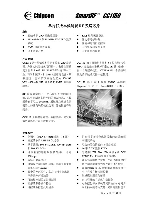
第 - 2 - 页 共 46 页
目录 1 缩写词 ......................................................................................................................................... 2 2 绝对最大等级 ............................................................................................................................. 5 3 工作条件 ..................................................................................................................................... 5 4 电气规范 ..................................................................................................................................... 5 5 常规特性 ..................................................................................................................................... 6 6 RF 传输环节 .............................................................
LS05-13BxxR3(-F)Series Mornsun高效绿色输入100~500V交流 直流变

5W,DIY AC/DC converterReportCB RoHSUL62368-1EN62368-1IEC62368-1BS EN 62368-1FEATURES●Ultra-wide 85-305VAC and 70-430VDC input voltage range ●Accepts AC or DC input (dual-use of same terminal)●Operating ambient temperature range -40℃to +85℃●Multi application,flexible layout●Compact size,high power density,green power ●Controllable life and adjustable cost ●No-load power consumption 0.1W●Output short circuit,over-current protection●UL/EN/IEC62368safety approval (LS05-13BxxR3series)●EN62368safety approval (LS05-13BxxR3-F series)LS05-13BxxR3(-F)series is one of Mornsun’s highly efficient green power AC-DC Converter series.They feature wide input range accepting either AC or DC voltage,high reliability,low power consumption and reinforced isolation.All models are particularly suitable for industrial control,electric power,instrumentation and smart home applications which have high requirement for dimension and don’t have high requirement on EMC.For extremely harsh EMC environment,we recommend using the application circuit show in Design Reference of this datasheet.Input SpecificationsItemOperating Conditions Min.Typ.Max.Unit Input Voltage Range AC input 85--305V AC DC input70--430VDC Input Frequency 47--63HzInput Current 115V AC ----0.2A 230V AC ----0.1Inrush Current115V AC --20--230V AC--40--Recommended External Input Fuse 1A,slow-blow,required(The actual use needs to be selected according to the application environment)Hot PlugUnavailableSelection GuideCertificationPart No.*Output PowerNominal Output Voltage and Current (Vo/Io)Efficiency at 230V AC(%)Typ.Capacitive Load(uF)Max.UL/EN/IECLS05-13B03R3 3.3W3.3V/1000mA 692200LS05-13B05R35W 5V/1000mA 761500LS05-13B09R39V/560mA 77680LS05-13B12R312V/420mA 79470LS05-13B15R315V/340mA 79330LS05-13B24R324V/210mA 81100ENLS05-13B03R3-F 3.3W 3.3V/1000mA 692200LS05-13B05R3-F5W 5V/1000mA 761500LS05-13B09R3-F 9V/560mA 77680LS05-13B12R3-F 12V/420mA 79470LS05-13B15R3-F 15V/340mA 79330LS05-13B24R3-F24V/210mA81100Note:1.The nominal output voltage refers to the voltage applied to the load terminal after adding external circuits.2.If the product is used in a severe vibration application,it needs to be glued and fixed.3.*An “-F”suffix designates horizontal package vs.standard vertical mounting.Output SpecificationsItem Operating Conditions Min.Typ.Max.Unit Output Voltage Accuracy10%-100%load--±5--% Line Regulation Rated load--±1.5--Load Regulation10%-100%load--±3--Ripple&Noise*20MHz bandwidth(peak-to-peak value),10%-100%load--80150mVTemperature Coefficient--±0.15--%/°C Stand-by Power Consumption230V AC--0.100.15W Short Circuit Protection Hiccup,continuous,self-recovery Over-current Protection≥110%Io,self-recovery Minimum Load10----% Note:1.*The“parallel cable”method is used for ripple and noise test,please refer to AC-DC Converter Application Notes for specific information;2.The product is able to work with0%-10%load and with stable output.General SpecificationsItem Operating Conditions Min.Typ.Max.UnitIsolation Input-output Electric Strength Test for1min.,leakage current<5mA3600----VAC5000----VDCOperating Temperature-40--+85℃Storage Temperature-40--+105Storage Humidity----95%RHSoldering Temperature Wave-soldering260±5℃;time:5-10s Manual-welding360±10℃;time:3-5sPower Derating +55℃to+85℃ 1.67----%/℃85V AC-100VAC 1.33----%/V AC 277V AC-305V AC0.72----Safety Standard LS05-13BxxR3seriesIEC/UL62368-1Safety Approval&BS EN/EN62368-1(Report);Design refer to IEC/EN60335-1,IEC/EN61558-1LS05-13BxxR3-F series BS EN/EN62368-1(Report)Safety Approval;Design refer to IEC/EN60335-1,IEC/EN61558-1Safety Class CLASS IIMTBF MIL-HDBK-217F@25℃>1,000,000h Mechanical SpecificationsDimension LS05-13BxxR326.40x14.73x11.00mm LS05-13BxxR3-F27.84x11.60x17.60mmWeight LS05-13BxxR3 5.2g(Typ.) LS05-13BxxR3-F 5.6g(Typ.)Cooling method Free air convection Electromagnetic Compatibility(EMC)Emissions CECISPR32/EN55032CLASS A(Application circuit1,4)CISPR32/EN55032CLASS B(Application circuit2,3) RECISPR32/EN55032CLASS A(Application circuit1,4)CISPR32/EN55032CLASS B(Application circuit2,3)Immunity ESD IEC/EN61000-4-2Contact±6KV perf.Criteria B RS IEC/EN61000-4-310V/m perf.Criteria AEFTIEC/EN61000-4-4±2KV(Application circuit1,2)perf.Criteria BIEC/EN61000-4-4±4KV(Application circuit3,4)perf.Criteria BSurge IEC/EN61000-4-5line to line ±1KV (Applicationcircuit 1,2)perf.Criteria B IEC/EN61000-4-5line to line ±2KV (Application circuit 3,4)perf.Criteria B CSIEC/EN61000-4-610Vr.m.sperf.Criteria A Voltage dip,shortinterruption and voltage variationIEC/EN61000-4-110%,70%perf.Criteria BProduct CharacteristicCurveNote:①With an AC input between 85-100VAC/277-305VAC and a DC input between 70-120VDC/390-430VDC,the output power must be derated as per temperature derating curves;②This product is suitable for applications using natural air cooling;for applications in closed environment please consult Mornsun FAE.Additional Circuits Design ReferenceLS series additional circuits design referenceLS05(-F)series additional components selection guide (No EMC devices)Part No.C1(required)C2(required)L1(required)C3(required)C4CY1(required)TVSLS05-13B03R3(-F)10uF/450V(-25℃to +85℃,85-305VAC input;-40℃to +85℃,165-305VAC input)22uF/450V(-40℃to +85℃,85-305VAC input)820uF/6.3V(solid-state capacitor)4.7uH/60m Ω/2.2A100uF/35V0.1uF/50V1.0nF/400V ACSMBJ7.0A LS05-13B05R3(-F)470uF/16V(solid-state capacitor)LS05-13B09R3(-F)270uF/16V(solid-state capacitor)47uF/35VSMBJ12A LS05-13B12R3(-F)SMBJ20A LS05-13B15R3(-F)220uF/35VLS05-13B24R3(-F)SMBJ30ANote:1.C1is used as filter capacitor with AC input (must be connected externally)and as EMC filter capacitor with DC input (must be connected),and it is recommended to use the capacitor with ripple current >200mA@100KHz .2.We recommend using an electrolytic capacitor with high frequency and low ESR (ESR of C3at low temperature of -40℃≤1.1Ω)rating for C3(refer tomanufacture’s datasheet),electrolytic capacitor can be used for C2when applied in normal and high temperature bined with C2,L1,they form a pi-type filter circuit.Choose a capacitor voltage rating with at least 20%margin,in other words not exceeding 80%.C4is a ceramic capacitor,used for filtering high frequency noise.3.A suppressor diode (TVS)is recommended to protect the application in case of converter failure and specification should be 1.2times of the output voltage.4.LDM (1.2mH,P/N:12050373;4.7mH,P/N:12050305),L1(4.7uH,P/N:12050181)Mornsun quotation is available.Environmental Application EMC SolutionLS series environmental application EMC solution selection tableRecommendedcircuitApplication environmental Typical industryInput voltagerangeEnvironment temperature Emissions Immunity 1Basic application None85-305V AC-40℃to +85℃Class A Level 32Indoor civil environment Smart home/Home appliances(2Y)-25℃to +55℃Class BLevel 3Indoor general environment Intelligent building/Intelligentagriculture 3Indoor industrial environment Manufacturing workshop -25℃to +55℃Class B Level 44Outdoor general environmentITS/Video monitoring/Charging point/Communication/Securityand protection-40℃to +85℃Class ALevel 4Immunity design circuits for referenceEmissions design circuits for referenceLevel 3Level 4Class AClass BElectromagnetic Compatibility Solution--Recommended Circuit1.Application circuit 1——Basic applicationrecommended circuit 1Application environmentalAmbient temperature rangeImmunity LevelEmissions ClassBasic application-40℃to +85℃Level 3Class AFUSE (required)1A/300V ,slow-blowR1(wire-wound resistor,required)12Ω/3WLDM4.7mH/Max:15Ω/Min:0.2ANote:R1is the input plug-in resistor,this resistor needs to be a wire-wound resistor (required),please do not select SMD resistor or carbon film resistor.2.Application circuit2——Indoor civil/Universal system recommended circuits for general environmentRecommended circuit2Application environmental Ambient temperature range Immunity Level Emissions Class Indoor civil/general-25℃to+55℃Level3Class BComponent Recommended valueR1(wire-wound resistor,required)12Ω/3WLDM 1.2mH/Max:4.0Ω/Min:0.2ACX0.1uF/310VACFUSE(required)1A/300V,slow-blow Note1:In the home appliance application environment,the two Y capacitors of the primary and secondary need to be externally connected (CY1/CY2,value at2.2nF/250VAC),which can meet the EN60335certification.Note2:According to the certification requirements,the X capacitor needs to be connected in parallel with the bleeder resistance,therecommended resistance value is less than3.8MΩ,and the actual need to be selected according to the certification standard.Note3:R1is the input plug-in resistor,this resistor needs to be a wire-wound resistor(required),please do not select SMD resistor or carbon film resistor. 3.Application circuit3——Universal system recommended circuits for indoor industrial environmentRecommended circuit3Application environmental Ambient temperature range Immunity Level Emissions ClassIndoor industrial-25℃to+55℃Level4Class BComponent Recommended valueMOV S14K350CX0.1uF/310V ACLDM 1.2mH/Max:4.0Ω/Min:0.2AR1(wire-wound resistor,required)12Ω/3WFUSE(required)2A/300V,slow-blow Note1:According to the certification requirements,the X capacitor needs to be connected in parallel with the bleeder resistance,the recommended resistance value is less than3.8MΩ,and the actual need to be selected according to the certification standard.Note2:R1is the input plug-in resistor,this resistor needs to be a wire-wound resistor(required),please do not select SMD resistor or carbon film resistor.4.Application circuit4——Universal system recommended circuits for outdoor generalenvironmentRecommended circuit4Application environmental Ambient temperature range Immunity Level Emissions ClassOutdoor general-40℃to+85℃Level4Class AenvironmentComponent Recommended valueMOV S14K350LDM 4.7mH/Max:15Ω/Min:0.2AR1(wire-wound resistor,required)12Ω/2WFUSE(required)2A/300V,slow-blow Note:R1is the input plug-in resistor,this resistor needs to be a wire-wound resistor(required),please do not select SMD resistor or carbon film resistor.5.For additional information please refer to LS-R3DIY AC-DC Converter Application Guide And Design Reference.LS05-13BxxR3Dimensions and Recommended LayoutLS05-13BxxR3series dimensionsLS05-13BxxR3series recommended padNote:There is a slot(non-metallic hole)between pin4/5,which the side pad were being cut off.For details,please refer to the recommended dimensions or pad.LS05-13BxxR3-F Dimensions and Recommended LayoutLS05-13BxxR3-F series dimensionsLS05-13BxxR3-F series recommended padNote:There is a slot(non-metallic hole)between pin4/5,which the side pad were being cut off.For details,please refer to the recommended dimensions or pad.Note:1.For additional information on Product Packaging please refer to .Packaging bag number:58220084(LS05-13BxxR3);58220093(LS05-13BxxR3-F);2.External electrolytic capacitors are required to modules,more details refer to typical applications;3.This part is open frame,at least6.4mm creepage distance between the primary and secondary external components of the module isneeded to meet the safety requirement,refer to the recommended welding hole design in the external dimension drawing;4.Unless otherwise specified,parameters in this datasheet were measured under the conditions of Ta=25℃,humidity<75%,nominal inputvoltage(115V and230V)and rated output load;5.All index testing methods in this datasheet are based on our company corporate standards;6.We can provide product customization service,please contact our technicians directly for specific information;7.Products are related to laws and regulations:see"Features"and"EMC";8.If product involves multi-brand materials and there are differences in color etc,please refer to the standards of each manufacturer;9.Our products shall be classified according to ISO14001and related environmental laws and regulations,and shall be handled byqualified units.Mornsun Guangzhou Science&Technology Co.,Ltd.Address:No.5,Kehui St.1,Kehui Development Center,Science Ave.,Guangzhou Science City,Huangpu District,Guangzhou,P.R.China Tel:86-20-38601850Fax:86-20-38601272E-mail:***************。
Bosch Rexroth Canada 罗克沙 雪花盐控制器 CS-520 技术手册 05.201

Compu-Spread CS 520 Solids Controller05.2018CS-520_datasheet,Bosch Rexroth Canada▶Two function programmable controller, available Manual, Closed or Open loop mode, for the controlled application of granular solids in snow and ice control.Features•5.5” organic light emitting diode (OLED) display •On-screen display of storm and season totals •2 frequency inputs (ground speed, conveyor) •2 proportional, current compensated PWM outputs (programmable dither frequency) for spinner & conveyor •1 digital output (reverse, air gate or ground speed) •USB key or password-protected calibration values •Operating parameters and event data can be retrieved by USB memory stick•Automatic nulling and material calibration (with Closed Loop version only)•Remote Pause and Blast with detachable cable •Adjustable Blast setting•Solenoid and cable failure detection •Firmware upgradable via USBThe CS-520 controller is designed for two axis spreader applications, with manual control of one axis (Spinner) and manual, ground speed triggered manual, open or closed loop regulation of the other. It has a large high contrast solid state OLED display. Two heavily detented knobs are for the Conveyor and Spinner functions, each with 9 settings. The push buttons integral to the control knobs are for Blast and Pause functions. Five touch pads below the display are used in the setup mode.System setup and calibrations are easily accomplished with on-screen text defined parameters, and separate selection buttons. Vehicle speed and material calibration are quickly setup with on-screen prompts. Four materials can be set-up. Error messages are text defined, and are augmented by an audible alarm. The USB port provides controlled access to event logging and calibration, as well as any firmware upgrades. A serial port for diagnostics and AVL interface is standard.The CS-520 is built around a high performance 32 bit processor with many advanced features. All components, connectors and operating devices are industry proven, fitted into a rugged extrusion made to withstand the rigours – and temperatures – of winter.The CS-520 complements the Compu-Spread family of snow and ice control products and solutions from Bosch Rexroth. It is ideally suited for the control of the large range of Rexroth hydraulic valves and modules, which find broad usage in these demanding applications.2Compu-Spread CS 520 Solids ControllerBosch Rexroth Canada , CS-520_datasheetBosch Rexroth Canada490 Prince Charles Drive S Welland, ON L3B 5X7Phone: (905) 735-0510Toll Free: 1-877-COMPU-11********************www.boschrexroth.ca/cs© Bosch Rexroth Canada Corp. This document, as well as the data, specifications and other information set forth in it, are the exclusive property of Bosch Rexroth. It may not be reproduced or given to thirdparties without its consent. The data specified above only serve to describe the product. No statements concerning a certain condition or suitability for a certain application can be derived from our information. The information given does not release the user from the obligation of own judgement and verification. it must be remembered that our products are subject to anatural process of wear and aging. Subject to change.GeneralMechanical Mounting“Ram Bracket”, size 1-½”Technical DataEnvironmental* The charts above are for reference and provided as general information only.Electrical VibrationISO 16750-3 10-2000 Hz at 58m/s; IEC 60068-2-72 40G for 11 ms。
克罗韦尔CompactLogix 5380和Compact GuardLogix5380控制器说明书

CompactLogix 5380 和 Compact GuardLogix 5380 控制器产品目录号 5069-L306ER 、5069-L306ERM 、5069-L310ER 、5069-L310ERM 、5069-L310ER-NSE 、5069-L310ERS2、5069-L320ER 、5069-L320ERM 、5069-L330ER 、5069-L330ERM 、5069-L340ER 、5069-L340ERM 、5069-L350ERM 、5069-L380ERM 、5069-L3100ERM 、5069-L306ERS2、5069-L306ERMS2、5069-L310ERS2、5069-L310ERMS2、5069-L320ERS2、5069-L320ERS2K 、5069-L320ERMS2、5069-L320ERMS2K 、5069-L330ERS2、5069-L330ERS2K 、5069-L330ERMS2、5069-L330ERMS2K 、5069-L340ERS2、5069-L340ERMS2、5069-L350ERS2、5069-L350ERS2K 、5069-L350ERMS2、5069-L350ERMS2K 、5069-L380ERS2、5069-L380ERMS2、5069-L3100ERS2、5069-L3100ERMS2用户手册原版说明书的中文译本重要用户须知在安装、配置、操作或维护本产品前,请仔细阅读本文档以及其他资源部分列出的文档,以了解有关此设备的安装、配置和操作信息。
用户需熟悉所有适用准则、法律及标准要求以及安装和接线说明。
安装、调节、投入使用、操作、装配、拆卸和维护等活动均要求由经过适当培训的人员遵照适用法规执行。
如果未按照制造商指定的方式使用设备,其提供的保护可能会受影响。
对于由于使用或应用此设备而导致的任何间接损失或连带损失,罗克韦尔自动化在任何情况下都不承担任何责任。
cl-5

b.电压表后接 电压表后接
Ux R Rx V ′′ = Rx = I R + Rx V
R′′ − Rx -Rx x γ′′ = = Rx R + Rx V
方法误差为负。 方法误差为负。适用于 Rx << RV 。 测量较 小电阻 伏安法测电阻的实用意义: 伏安法测电阻的实用意义: 在被测电阻的工作状态下进行测量。 在被测电阻的工作状态下进行测量。
第三节 直流双电桥
一、双电桥电路构成
直流双电桥也是由检流计、比率臂和比较臂组成。比率 臂为两对可同步调节的可调电阻,电流接头 C1 、 CS2 之间 用一条的粗母线连接。
用于测量 小电阻。 小电阻。
平衡时,检流计两端等电位。关于三个回路列方程: 平衡时,检流计两端等电位。关于三个回路列方程:
I1R1 = Rs Is + R1′I3 I1R2 = R2′I3 + Rx Is I3R1′ + I3R2′ = R0 (Is -I3 )
注 意 例
测量前应估计待测电阻的数值, 测量前应估计待测电阻的数值,以选择合适的 比率,使比较臂的电阻位数能全部用到。 比率,使比较臂的电阻位数能全部用到。 QJ23型单电桥,比例臂分七个档位,分别为 型单电桥,比例臂分七个档位, 型单电桥
10−3、 −2、 −1、10、 2、 3 。比较臂电阻范围是 10 10 1 10 10 、
练习1 练习 伏安法测200Ω的电阻,若电压表内阻 的电阻, 伏安法测 的电阻 2kΩ,电流表内阻 ,电流表内阻0.03Ω。分别计算电压表前 。 后接时的测量误差。 接、后接时的测量误差。
比较法) 4、直流单电桥(又称惠斯登电桥) (比较法 、直流单电桥(又称惠斯登电桥) 比较法
cl2005说明

CL2005通讯屏管理系统使用说明(V1.3)12006年3月2目录第一章概述 (5)第二章安装与运行 (5)第一节安装 (5)第二节运行 (6)第三章系统设置 (8)第一节通讯设置 (8)第二节显示屏规格、自动开关屏时间设置 (8)第四章节目制作 (9)第一节选择要播放的图片 (9)第二节设定图片的播放顺序 (10)第三节设计图片的播放效果 (11)第四节编辑原始文件 (12)第五章通讯 (12)第一节发送数据 (12)第二节控制显示屏电源 (13)第三节汉字点阵库 (13)第六章时钟版面设计 (14)第一节显示时钟 (15)第二节显示“安全天数” (16)第七章多屏信息管理、多用户管理及日志 (17)第一节多屏信息管理 (17)3第二节多用户管理 (18)第三节日志 (19)4第一章概述CL2005通讯屏管理系统是一套全新的节目制作管理系统。
用户使用它制作节目时简单直接。
节目的数据来源可以是图片、文本文件或Word文档,更可以直接输入颜色字体可变化的文本信息。
CL2005系统可播放安全天数,可实现精确到分的定时播放,还可以实现每天的定时开关显示屏。
对已经上载到显示屏的图片或文字信息,CL2005还提供点播功能,即只播放其中的部分节目内容。
CL2005系统支持RS232通讯模式和RS422、RS485通讯模式。
通过外接的扩展设备,CL2005系统还支持调制解调器、以太网等有线远程通讯模式和GPRS无线远程通讯模式。
运行CL2005系统需要Microsoft Office 2000或Microsoft Office XP 的支持。
推荐在Windows XP以及Office XP环境下运行。
第二章安装与运行第一节安装在计算机上运行CL2005Setup.exe程序,屏幕上出现如下的画面:56点击[开始]即可将CL2005通讯屏管理系统安装到计算机上。
第二节 运行在[开始]菜单中,选择[程序]->[CL2005通讯屏管理系统]->[CL2005]即可启动CL2005通讯屏管理系统。
