OTE9120-9140说明书-V1.0
奥斯恩智能科技产品手册说明书

目录ATALOG01企业简介company profileP0402技术研发团队Technical research and development teamP0503生产实力production abilityP06P11声环境监测系列P24智慧环境监测系列P42粉尘颗粒物监测系列P46自然生态环境系列01P72安全应急监测系列P84走航环境监测系列P86便携式手持式监测系列P87A I智能识别系列P61水文水质监测系列04荣誉资质Honor QualificationP0705产品中心Product centerP1002P96大数据服务P97O E M /O D M定制化服务P94物联网传感器P96信息化软件平台06SolutionP98解决方案08合作伙伴招募Partner recruitmentP10007项目业绩Project performanceP99奥斯恩2012年创立于深圳宝安区,国家高新技术企业,深圳市高新技术企业,创新型中小企业,科技型中小企业,AIOT智能互联整体解决方案提供商。
奥斯恩是一家依托AIOT智能互联技术感知,融合物联网、云计算、大数据、人工智能AI、区块链、遥感技术、移动互联网等新一代信息技术,专注于声学环境、智慧环境、应急安全、自然生态、水文水质、AI视觉识别领域仪器设备研发制造、销售与安装运维,跨领域信息化软件平台开发,环境综合应用服务的研发制造型企业。
奥斯恩以市场需求为研发导向,以技术创新为发展驱动,业务始终围绕“产品+应用解决方案+数据服务”展开,产品定位于中高端市场,广泛应用于生态环境、安全,应急监测、城市管理、智慧工地、声环境监测、电力、垃圾焚烧、水泥、钢铁、空分、石油化工、园林水利、智慧农业、畜牧业及科研院校等领域。
03由生态环境和跨界领域资深研发型技术负责人牵头,奥斯恩组建了一支软件开发、嵌入式开发、单片机开发、光学电子、仪器仪表、结构设计、AI算法、环境气象学背景组成的核心研发团队,擅长AIOT领域硬件产品研发,大数据软件平台开发和项目技术攻克。
TOP9140M-20E电动机保护控制器使用说明书(v2[1].01)OK
![TOP9140M-20E电动机保护控制器使用说明书(v2[1].01)OK](https://img.taocdn.com/s3/m/20ece13783c4bb4cf7ecd142.png)
2.6 机械性能
振 动: 冲 击: 碰 撞:
测控仪能承受IEC标准规定的严酷等级为I 级的振动耐久能力试验 测控仪能承受IEC标准规定的严酷等级为I 级的冲击耐久能力试验 测控仪能承受IEC标准规定的严酷等级为I 级的碰撞耐久能力试验
2.7 抗电磁干扰(EMC)性能
测控仪能够通过以下几种国家、国际标准的抗电磁干扰实验:
交流输入电流: 250A 以内,采用内置 CT(6.3A/25A/100A /250A 等); (2 倍过载连续工作,10 倍过载 20S) 250A 以上,采用标准 CT(二次侧额定 5A 或 1A);(10 倍过载连续工作)
开关量输入: 共 12 路,可全部采用干接点输入或 有源输入,有源输入电源可以是 DC220V/110V/48/24V 或 AC220V/110V
2
TOP9140M-20E 使用说明书
第二章 技术指标
2.1 环境要求指标
工作环境:
海拔: 抗震:
工作温度:-10℃~55℃ 贮存温度:-20℃~75℃ 相对湿度: <95%, 可达 2000 米 10g/5ms
2.2 技术参数
装置电源:
频 率: 功率消耗:
85~265VAC 或 88V~346VDC (订货时请注明) 对于比较重要的电动机可以选择配置双电 源模块输入(两路电源均交直流通用) 50Hz(额定) 电源回路不大于 8W(正常运行) /12W(保护动作) 交流电压回路不大于 0.5VA/相 交流电流回路不大于 0.5VA/相
3
第一章 概
TOP9140M-20E 使用说明书
述
1.1 概 述
TOP9140M-20E 电动机保护控制器是一种数字式智能型电动机 保护控制设备,直接针对一台低压电动机设计,能够完成一台低压 电动机的测量、控制及辅助保护功能,具有很高的性能价格比。
MOTEC α系列伺服使用手册v1.1
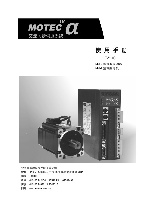
使用手册
(V1.0)
SED 型伺服驱动器 SEM 型伺服电机
北京意美德科技发展有限公司 地址: 北京市东城区东中街 58 号美惠大厦 B 座 703A 邮编: 100027 电话: 010-65542170、65546546、65542692 传真: 010-65546721 65547015 网址:
α系列伺服电机系统使用手册
章 节:
第 1 章. 伺服电机与驱动器型号 第 2 章. 安装和配线 第 3 章. 驱动器 JP2 接口(I/O 控制信号)功能说明 第 4 章. 面板操作操作说明 第 5 章. 性能调整功能说明 第 6 章. 控制模式 第 7 章. 监视项 第 8 章. 伺服驱动器工作时序图 第 9 章.驱动器 JP3/JP4(通信端口)定义、接线及通信协议 附录 1: 驱动器参数列表 附录 2:故障信息、故障原因及处理措施 附录 3:SEM 电机电气参数
1. 伺服电机与驱动器型号 ................................................................. 5 1.1 伺服电机型号定义 ................................................................. 5 1.2 伺服驱动器型号定义 ............................................................... 6 1.3 α系列驱动器与电机组合 ........................................................... 6 1.4 α系列驱动器外形及安装尺寸图 ..................................................... 8
FOSS官方资料 FT120中文操作手册
MilkoScan FT-120乳品分析仪中文操作手册北京福斯杰科技有限公司F os s C hi na Se r vi c e Ce n te r2000年6月目录第1章简介 (5)§1。
1FT—120乳品分析仪 (5)§1。
2关于这本手册 (6)§1。
3福斯电子的校准模块 (6)§1。
4FT—120仪器可选择的模块 (7)§1。
4。
1自动清洗和调零模块(ACZ) (7)§1。
4。
2 应用模块 (7)§1。
4。
3 天平选项 (7)§1。
4。
4 高级性能模块 (7)§1。
4。
5高级校准模块 (8)§1。
4。
6 输入选择模块 (8)§1。
4。
7 数据交换选择模块(DDE) (8)§1。
4。
8 品质确认模块 (8)§1。
5窗口系统 (9)§1。
5。
1 菜单栏 (9)§1。
5。
2 功能键 (10)§1。
5。
3 按钮栏 (10)§1。
5。
4 滚动栏 (10)§1。
5。
5 状态栏 (10)§1。
6定义自己的窗口 (10)§1。
7仪器语言支持 (10)§1。
7。
1 怎样使用当地语言 (11)§1。
8激光的保险装置 (11)第2章FT—120乳品分析仪用户界面 (11)§2。
1FT—120乳品分析仪插图屏幕说明 (12)§2。
2按钮板 (13)§2。
3功能键 (13)§2。
4快捷键 (14)§2。
5其它菜单 (14)§2。
6菜单概要 (15)§2。
6。
1 菜单中的基本模块 (15)§2。
6。
2 应用模块菜单 (16)§2。
7物理连接与转换 (16)第3章操作 (18)§3。
1调零和实验样品 (18)§3。
SENNHEISER e 914 使用说明书

e 914使用说明书供货范围供货范围• e 914• 个话筒夹 MZQ 800• 防风屏MZW 64• 个话筒包• 简要说明•安全提示本款麦克风与K6电源转换插头不匹配。
产品总览1. 收音头2. XLR-3 插孔3. 调整灵敏度4. 调整低音开关安装固定麦克风f将话筒夹 拧在三脚架上。
f将麦克风的末端插在话筒夹上。
f调整麦克风与话筒夹 对齐。
连接麦克风f将麦克风电缆的XLR-3 插头插 (选配附件) 入麦克风的XLR-3 插头内。
使用防风罩f装上 MZW 64 (选配附件) 防风屏。
操作定位麦克风: 打击/敲击乐器注意:合闭踩镲时会产生强烈的气流!如麦克风距离边缘太近,可能由于气流产生干扰噪音。
f务请遵守下列提示:位置注释A将麦克风向下对准踩镲,距离边缘数厘米。
通过高通滤波消除不需要的声音部分。
B现场拾音时良好的起始位置。
如高架式麦克风只用于铙钹录音,不需要的声音部分可通过高通滤波消除。
为避免邻近声源串扰,尝试调整麦克风位置,使干扰声源位于最大抵消角度范围(180°,见极性特征图)内。
定位显示器扬声器f将显示器扬声器定位于最大抵消角度范围内(约 180°),以避免声音回馈和串扰。
前置衰减和灵敏度e 914配有可开关集成前置衰减(灵敏度)和低音滤波器。
调整灵敏度麦克风灵敏度的设置可以选择不改变(0)、降低10 dB或降低20 dB。
如存在麦克风或后接麦克风输入端过调的危险,比如由打击或金属管乐器的高声压级导致,则推荐这一调整。
在插拔麦克风线、接通和关闭幻象电源及操作开关(见图)前,建议在混音器上将相应的麦克风通道静音。
.调整低音开关e 914针对生动的低音再现而设计。
乐器的现场或近距离拾音有时会出现低频过强的现象。
这可以通过6 dB/Oct.的滚降滤波器消除。
低频风噪可通过低切滤波器按照18 dB/Oct.进行校正。
E 914 的清洁和保养E 914 的清洁和保养注意液体会损坏产品的电子线路!如果液体流入产品外壳,则会导致电路短路。
HEDS-9140中文资料
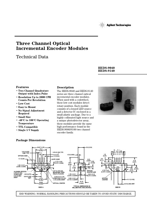
The HEDS-9040 and 9140 provide sophisticated motion control detection at a low cost, making them ideal for high volume applications. Typical applications include printers, plotters, tape drives, and industrial and factory automation equipment.
2.16 (0.085) DEEP
1.78 ± (0.070 ± 0.004)
2.92 ± 0.10 (0.115 ± 0.004)
OPTICAL CENTER
10.16 (0.400)
OPTICAL CENTER LINE
5.46 ± 0.10 (0.215 ± 0.004)
TYPICAL DIMENSIONS IN MILLIMETERS AND (INCHES)
元器件交易网
Three Channel Optical Incremental Encoder Modules
Technical Data
HEDS-9040 HEDS-9140
Features
• Two Channel Quadrature Output with Index Pulse
1.52 (0.060)
DATE CODE
3.73 ± 0.05 (0.147 ± 0.002)
20.8 (0.82)
11.7 (0.46)
2.21 (0.087) 2.54
(0.100)
2.67 (0.105) DIA. MOUNTING THRU HOLE 2 PLACES
EXFO RTU-2 基于OTDR的远端测试单元产品说明书

规格书基于OTDR 的远端测试单元RTU-2测试接入模块(TAM )套装可靠性高的1XN MEMS 光开关MPO 16纤芯连接器 有多个型号,分别配备32、64、128和256个端口体积小——仅有1/2U 高端口密度高:最高可达512个端口/1U 在支持高端口数的同时,其插损极低使用寿命超过25亿次 能耗极低PON/FTTx 机房内远程测试和监测大规模节点或边缘节点光纤测试和监测大纤芯数据中心互连和园区监测RTUe-9120外接光开关提供非常高的光开关端口密度,适用于基于OTDR 的远程光纤测试系统和光纤监测应用。
端口密度非常高的1XN MEMS 型光开关RTUe-9120如欲了解最新的专利标识标注信息,敬请访问/patent 。
EXFO 产品已获得ISO 9001认证,可确保产品质量。
EXFO 始终致力于确保本规格书中所包含的信息的准确性。
但是,对其中的任何错误或遗漏,我们不承担任何责任,而且我们保留随时更改设计、特性和产品的权利。
本文档中所使用的测量单位符合SI 标准与惯例。
此外,EXFO 制造的所有产品均符合欧盟的WEEE 指令。
有关详细信息,请访问/zh/corporate/social-responsibility 。
如需了解价格和供货情况,或查询当地EXFO 经销商的电话号码,请联系EXFO 。
如需获得最新版本的规格书,请访问EXFO 网站,网址为/specs 。
如打印文献与Web 版本存在出入,请以Web 版本为准。
扫描EXFO 二维码, 获取通信网络优化解决方案EXFO 公司总部 电话:+1 418 683-0211 免费电话:+1 800 663-3936(美国和加拿大)EXFO 中国 北京市海淀区中关村南大街12号天作国际中心写字楼1号楼A座第二十五层(邮编:100081) 电话:+86 10 89508858EXFO 为100多个国家的2000多家客户提供服务。
如欲了解当地分支机构联系详情,敬请访问/zh/contact 。
9.8 A3000技术规格说明书V1.0
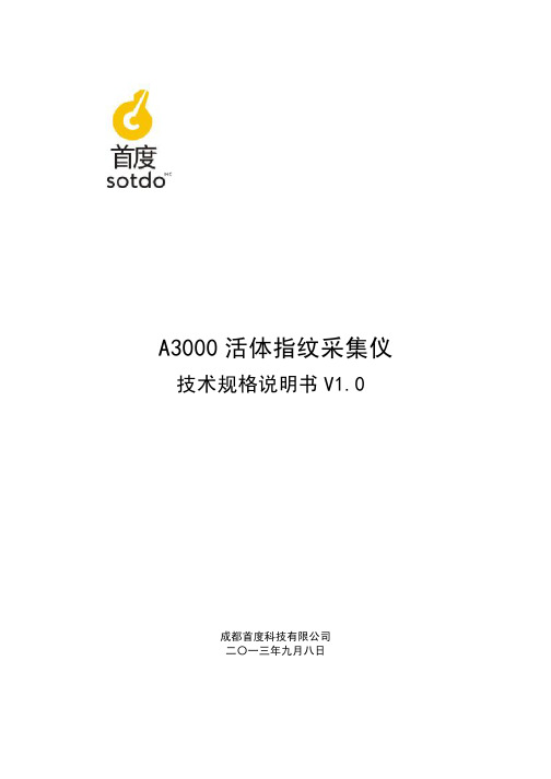
A3000活体指纹采集仪技术规格说明书V1.0成都首度科技有限公司二〇一三年九月八日目录1.产品介绍 (3)2.产品图片 (3)3.产品功能 (4)4.技术参数 (4)1.产品介绍A活体指纹采集仪由东方金指自主研发并制造的高质量、成熟的光学成像方式指纹采集仪,广泛应用于公安刑侦三面指纹采集、公安出入境指纹采集与验证、民用身份证件和安全防范等领域的指纹采集和验证。
现已拥有百分之三十以上的市场份额。
通过“公安部安全与警用电子产品质量检测中心”检测,以及“中国安全技术防范认证中心”认证,具备GA认证标志。
完全符合《公安出入境管理用指纹采集设备接口规范》和《公安出入境管理电子旅行证件指纹采集设备技术规范》要求。
首批通过公安部第一研究所居民身份证指纹采集器检验合格的产品。
应用领域及用户:公安刑侦领域:配合活体指纹采集软件采集三面指纹,江西、山东、上海、新疆、辽宁等省市一万多套活体指纹采集系统。
在全国,至少有两万多个派出所使用东方金指的警用活体指纹采集系统。
公安出入境领域:山东、上海、黑龙江、江苏、安徽、新疆、内蒙等省市电子护照项目2500余套。
2.产品图片3.产品功能l指纹图像采集:拼接采集三面滚动指纹或平面指纹自动提示、有效控制指纹图像质量指纹图像自动切割、旋正方向指纹图像特征提取与压缩采用高分辨率的单色光电转换芯片,保证指纹图像的细节清晰提供标准接口程序l指纹比对认证:指纹图像采集、特征提取、比对验证指纹特征值小,比对速度快干、脱皮、粘连、老年人等差指纹仍可比对提供标准接口程序4.技术参数项目描述采集窗口尺寸36mm×36mm有效图像尺寸32.5mm×32.5mm图像像素640像素×640像素图像分别率500dpi图像畸变≤1%图像灰度级256级采集速度≥20帧/s接口USB2.0操作系统WINDOWS 7/XP畸变矫正光学物理矫正成像原理暗背景采集窗口材质光学石英玻璃固定支架合金铝支架成像芯片单色光电转换芯片。
IT9121 用户指南

请勿使用已损坏的设备。在使用设备之前,请先检查其外壳。检查是否存在 裂缝或缺少塑胶。请勿在含有易爆气体、蒸汽或粉尘的环境中操作本设备。 功率表的电压和电流测量端子可测试电压最大为 600V、 电流为 20A, 请勿接 入过高的电压和电流,否则会烧坏设备! 请始终使用所提供的电缆连接设备。 在连接设备之前,请观察设备上的所有标记。 在连接 I/O 端子之前,请关闭设备和应用系统的电源。 请勿自行在仪器上安装替代零件,或执行任何未经授权的修改。 请勿在可拆卸的封盖被拆除或松动的情况下使用本设备。 请勿在进行自测试之前连接任何电缆和端子块。 请仅使用制造商提供的电源适配器以避免发生意外伤害。 严禁将本设备使用于生命维持系统或其他任何有安全要求的设备上。
安全声明
手册部件号
IT9121-402145
版本
第2版, 2015 年 2月 27 日 发布 Itech Electronics, Co., Ltd.
小心标志表示有危险。它要求在 执行操作步骤时必须加以注意, 如果不正确地执行或不遵守操作 步骤,则可能导致产品损坏或重 要数据丢失。在没有完全理解指 定的条件且不满足这些条件的情 况下,请勿继续执行小心标志所 指示的任何不当操作。
安全标志
直流电 交流电 既有直流也有交流电 保护性接地端子
ON(电源合) OFF(电源断) 电源合闸状态 电源断开状态
接地端子 危险标志 警告标志(请参阅本手册了解 具体的“警告”或“小心”信息) 地线连接端标识 -
SPS-9140WG资料

Optoway SPS-9140WG********************************************************************************************************************************************************************************************************************************************************************************************************************************************OPTOWAY TECHNOLOGY INC. No .38, Kuang Fu S. Road, Hu Kou, Hsin Chu Industrial Park, Hsin Chu, Taiwan 303Tel: 886-3-5979798 Fax: 886-3-597973712/1/2005 V2.0 1SPS-9140WG / SPS-9140BWG (RoHS Compliant)3.3V / 1310 nm / 2.5 Gbps Digital Diagnostic SFP LC SINGLE-MODE TRANSCEIVER *********************************************************************************************************************************************************************FEATURESl Hot-Pluggable SFP Footprint LC Optical Transceiver l Small Form-Factor Pluggable (SFP) MSA compatible l Compliant with SONET OC-48 (LR-1) / SDH STM-16 (L-16.1)l Compliant with Fibre Channel 1x/2x SM-LC-L FC-PI l Compliant with IEEE 802.3z 1000BASE l SFF-8472 Digital Diagnostic Function l 1310 nm DFB LD Transmitter l APD High Sensitivity Receiver l 26 dB Power Budget at Leastl AC/AC Coupling according to MSA l Single +3.3 V Power Supply l RoHS Compliantl 0 to 70o C Operation : SPS-9140WG l -10 to 85o C Operation : SPS-9140BWGl Class 1 Laser International Safety Standard IEC-60825 CompliantAPPLICATIONSl ATM Switches and Routersl SONET / SDH Switch Infrastructure l XDSL Applications l Metro Edge SwitchingDESCRIPTIONThe SPS-9140WG series single mode transceivers is small form factor pluggable module for bi-directional serial optical data communications such as SONET OC-48 / SDH STM-16, Gigabit Ethernet 1000BASE and Fibre Channel 1x/2x SM-LC-L FC-PI. It is with the SFP 20-pin connector to allow hot plug capability. Digital diagnostic functions are available via an I 2C. This module is designed for single mode fiber and operates at a nominal wavelength of 1310 nm. A guaranteed minimum optical link budget of 26 dB is offered which can correspond to a link distance of over 40 km (assuming worst case fiber loss of 0.45 dB/km). The transmitter section uses a multiple quantum well 1310 nm DFB laser and is a class 1 laser compliant according to International Safety Standard IEC-60825. The receiver section uses an integrated InGaAs detector preamplifier (IDP) mounted in an optical header and a limiting post-amplifier IC.LASER SAFETYThis single mode transceiver is a Class 1 laser product. It complies with IEC-60825 and FDA 21 CFR 1040.10 and 1040.11. The transceiver must be operated within the specified temperature and voltage limits. The optical ports of the module shall be terminated with an optical connector or with a dust plug.ORDER INFORMATIONP/No.Bit Rate (Gb/s)SONET /SDH Distance (km) Wavelength (nm) Package Temp. (oC) TX Power (dBm) RX Sens. (dBm) RoHSCompliant SPS-9140WG 2.488 LR-1/L-16.1 40 1310DFB LC SFP with DMI 0 to 70 3 to -2 -28 Yes SPS-9140BWG 2.488LR-1/L-16.1 40 1310DFB LC SFP with DMI -10 to 85 3 to -2 -28 YesAbsolute Maximum RatingsParameterSymbol Min Max Units NotesStorage TemperatureTstg -40 85 o COperating Case Temperature Topr 0 -10 70 85 o C SPS-9140WG SPS-9140BWG Power Supply VoltageVcc-0.53.6VRecommended Operating ConditionsParameterSymbol Min Typ Max Units / NotesPower Supply VoltageVcc 3.1 3.3 3.5 VOperating Case Temperature Topr 0 -10 70 85 oC / SPS-9140WG oC / SPS-9140BWGPower Supply Current I CC (TX+RX)230 300 mA Data Rate62224882670Mb/s / 11. OC-48, Gigabit Ethernet and 1x/2x Fibre Channel compliant.Transmitter Specifications (0o C < Topr < 70o C, 3.1V < Vcc < 3.5V)Parameter Symbol Min Typ Max Units NotesOpticalOptical Transmit Power Po -2 --- 3 dBm 1Output Center Wavelength λ1280 1310 1335 nmOutput Spectrum Width ∆λ--- --- 1 nm -20 dB WidthSide Mode Suppression Ratio SMSR 30 dBExtinction Ratio E R8.2 --- --- dBOutput Eye Compliant with Telecordia GR-253-GORE and ITU-T Recommendation G.957Optical Rise Time t r150 ps 20 % to 80% Values Optical Fall Time t f150 ps 20 % to 80% Values Relative Intensity Noise RIN -120 dB/HzElectricalData Input Current – Low I IL-350 µAData Input Current – High I IH350 µADifferential Input Voltage V IH - V IL0.5 2.4 V Peak-to-PeakTX Disable Input Voltage – Low T DIS, L0 0.5 V 2TX Disable Input Voltage – High T DIS, H 2.0 Vcc V 2TX Disable Assert Time T ASSERT10 µsTX Disable Deassert Time T DEASSERT 1 msTX Fault Output Voltage -- Low T FaultL0 0.5 V 3TX Fault Output Voltage -- High T FaultH 2.0 Vcc+0.3 V 31. Output power is power coupled into a 9/125 µm single mode fiber.2. There is an internal 4.7K to 10K ohm pull-up resistor to VccTX.3. Open collector compatible,4.7K to 10K ohm pull-up to Vcc (Host Supply Voltage).Receiver Specifications(0o C < Topr < 70o C, 3.1V < Vcc < 3.5V)Parameter Symbol Min Typ Max Units NotesOpticalSensitivity Sens -28 dBm 4,5Maximum Input Power Pin -9 dBm 4,5Signal Detect -- Asserted Pa --- -28 dBm Transition: low to high Signal Detect -- Deasserted Pd -40 --- --- dBm Transition: high to low Signal detect -- Hysteresis 1.0 --- dBOptical Path Penalty 1 dBWavelength of Operation 1100 --- 1600 nmElectricalDifferential Output Voltage V OH– V OL0.6 2.0 VOutput LOS Voltage -- Low V OL0 0.5 V 6Output LOS Voltage -- High V OH 2.0 Vcc+0.3 V 64. Measured at 2-1 PRBS at BER 1E-10 @ 1300 nm.5. Measured at 27-1 PRBS at BER 1E-12 @ 1300 nm for 2.125 Gb/s, 1.25Gb/s, and 1.063 Gb/s.6. Open collector compatible, 4.7K to 10K ohm pull-up to Vcc (Host Supply Voltage).**************************************************************************************************************************************************************************** OPTOWAY TECHNOLOGY INC. No.38, Kuang Fu S. Road, Hu Kou, Hsin Chu Industrial Park, Hsin Chu, Taiwan 303****************************************************************************************************************************************************************************OPTOWAY TECHNOLOGY INC. No .38, Kuang Fu S. Road, Hu Kou, Hsin Chu Industrial Park, Hsin Chu, Taiwan 303PINSignal NameDescriptionPINSignal Name Description1 TX GND Transmitter Ground11 RX GND Receiver Ground2 TX Fault Transmitter Fault Indication12 RX DATA OUT- Inverse Receiver Data Out 3 TX Disable Transmitter Disable (Module disables on high or open)13 RX DATA OUT+ Receiver Data Out 4 MOD-DFE2 Modulation Definition 2 – Two wires serial ID Interface14 RX GND Receiver Ground5 MOD-DEF1 Modulation Definition 1 – Two wires serial ID Interface15 Vcc RX Receiver Power – 3.3V ±5% 6 MOD-DEF0 Modulation Definition 0 – Ground in Module16 Vcc TX Transmitter Power – 3.3V ±5% 7 N/C Not Connected 17 TX GNDTransmitter Ground 8 LOS Loss of Signal 18 TX DATA IN+ Transmitter Data In9 RX GND Receiver Ground 19 TX DATA IN- Inverse Transmitter Data In 10RX GNDReceiver Ground20TX GNDTransmitter GroundModule DefinitionModule DefinitionMOD-DEF2 PIN 4 MOD-DEF1 PIN 5 MOD-DEF0 PIN 6 Interpretation by Host 4SDASCLLV-TTL LowSerial module definitionprotocolModule Definition 4 specifies a serial definition protocol. For this definition, upon power up, MOD-DEF(1:2) appear as no connector (NC) and MOD-DEF(0) is TTL LOW. When the host system detects this condition, it activates the serial protocol. The protocol uses the 2-wire serial CMOS E 2PROM protocol of the ATMEL AT24C01A/02/04 family of components.**************************************************************************************************************************************************************************** OPTOWAY TECHNOLOGY INC. No.38, Kuang Fu S. Road, Hu Kou, Hsin Chu Industrial Park, Hsin Chu, Taiwan 303。
T91安装说明书
2
ૡपᆍ
Tele Thermo Top ᇹޘອࡼܪᓰ ૡपᆍ
1
23
4
ଝᓤݝୈૡपᆍ
1
23
5
6
6
1 T91 发送器 2 1 个 3.3V 电池 3 安装支架 4 T91 接收器 5 I 形适配器 6 天线
1 T91 发送器 2 1 个 3.3V 电池 3 安装支架 4 T91 接收器 5 Y 形适配器 6 天线
! !
I 形适配器 定时器插头
5
Telestart T91
ଝᓤ Telestart T91
ڔᓤ Y ተး
定时器插头 定时器
ᄋာǖ 不得拉动导线!
-把 4 芯插头从定时器上拔下
6
接收器 Y 形适配器
ᓖፀǖ Y 形适配器的作用是连接按钮开关或定时 器! 在使用按钮开关时,通过 Y 形适配器的黑色 导线,控制按钮开关里面安装的运行状态指 示灯。
-把 I 形适配器连接到 4 芯插头 -把 I 适配器插到 Telestart 接收器上
GSM 双工器
适配 线
-把现有的 D 网天线电缆连接到 GSM 双工器的输入端
-把适配线(长度190 mm)连接到GSM 双 工 器的 Telestart 的 输 入端 和 Telestart 接收器
- 把电话线连接到 GSM 双工器的电话输 出端
ᓖፀǖ 定时器和按钮开关向Telestart接收器发送不 同的信号! 输入信号必须与加热器的控制器相适应! 缺省时,Telestart 接收器的输入信号被调整 到与定时器的信号一致!
ࢾဟ
加热器启动时(通过按下立即加热按钮或者 预设的加热器运行开始时间的到达),在整 个运行时间内,Telestart 从定时器接收到持 续的信号。 加热器关闭时(通过按下立即加热按钮或者 预设的加热器运行终止时间的到达),电源 被切断,加热器被关闭。
DS-912FDS-914F 中文说明书
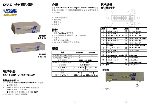
DVI分配器(DS-912F)1进 2 出(DS-914F)1 进 4 出用户手册DS-912F / DS-914F包装盒内包括—▪ 1 Smart View DS-912F或DS-914F DVI分配器▪1本用户手册▪DS-912F为1个DC 12V 600mA电源变压器,DS-914F为DC 12V 1.25A▪2条支架, 8个螺丝钉,仅附于DS-914F以上如有缺少,请与经销商联系。
介绍通过DS-912F/DS-914F DVI (Digital Visual Interface)分配器,你可以将一台主机的图像同时显示在2,4甚至更多台的显示器上。
DVI分配器适用场合:▪测试机房▪数据中心▪咨询台特性▪采用PanelLink数字技术。
▪支持的最高显示分辨率达UXGA(25-165MHz)。
▪可串联。
▪符合DVI 1.0标准。
▪DS-914F符合机架规范1U的高度。
规格-1-技术规格输入/输出信号前视图1. 电源灯-2-后视图1.电源输入接口2.“Video In”端口3.“DVI Out”端口* DS-912F / DS-914F分别有2/4个输出端。
安装1.关闭主机和显示器。
2.用DVI公头对公头的延长线把分配器的“video in”端口和主机连接起来。
3.用DVI公头对公头的延长线把分配器的“DVI out”和显示器连接起来。
4.接上电源,打开分配器。
5.打开主机和显示器。
注意:如果连接在分配器的其中有一台DDC显示器,其他的显示器也必须同DDC显示器有一样的分辨率。
串接操作:1.若要将同一个图像显示在多台显示器上时,可以另外串接分配器。
2.用DVI公头对公头的延长线,将前端分配器的“DVI Out 1”端口连接到后端分配器的“video In”端口上。
注意:虽然允许多级分配器的串接,但是如果串接级数太多可能会使显示图像不稳定。
-3-附注:上图例为串接2端口和4端口的分配器;不过,你可以随意串接不同端口数的DVI分配器,从而达到需求。
ZL_TXJK1101.0701 PCS-912(913)型继电保护专用收发信机 技术和使用说明书

附录一 电平的概念...................................................................................................................... 23
ZL_TXJK1101.0701
PCS-912/913 型 继电保护专用收发信机
技术和使用说明书
南瑞继保电气有限公司版权所有 V1.02 本说明书和产品今后可能会有小改动,请注意核对实际产品与说明书的版本是否相符。 更多产品信息,请访问互联网:
目录
第一章 PCS-912 型收发信机 ......................................................................................................... 1
1 装置简介 ................................................................................................................................ 1 2 装置特点 ................................................................................................................................ 1 3 技术参数 ................................................................................................................................ 2
罗宾康说明书5

.
.
PA 保护参数........................7 PB 通讯参数............................................................ 102 PC 高级功能参数及性能参数.............................................. 103 PE 面板功能设置及参数管理(PD 组保留) ................................. 108 PF 厂家参数............................................................ 110 第五章通讯协议............................................................. 111 5.1 RTU 模式及格式 ..................................................... 111 5.2 A600 的寄存器地址及功能码 .......................................... 111 5.3 其它寄存器地址功能说明:........................................... 117 5.4 变频器故障代码表:................................................. 118 5.5 变频器预告警代码表:............................................... 119 5.6 控制命令字格式(见写功能码 06H 实例):.............................. 119 5.7 参数属性表:....................................................... 119 5.8 从机回应异常信息的错误码含义:..................................... 120 5.9 A600 所有参数对应的通讯地址: ...................................... 120 第六章异常诊断与排除....................................................... 121 6.1 故障信息及排除方法 ................................................. 122 6.2 异常处理........................................................... 124 第七章保养与维护........................................................... 125 7.1 日常保养及维护 ..................................................... 125 7.2 定期保养及维护..................................................... 126
北京聚英翱翔电子有限公司气象百叶盒产品说明书V1.0

气象百叶盒采集器说明书V1.0北京聚英翱翔电子有限责任公司2021年5月目录一、产品介绍 (1)1、产品概述 (1)2、产品特点 (1)3、产品功能 (1)4、型号说明 (1)二、主要参数 (2)三、接口说明 (3)1、RS485接线 (3)2、4-20mA/0-10V接线 (3)四、通讯接线说明 (4)1、RS485级联接线方式 (4)2、模拟量接线方式 (4)五、开发资料说明 (5)1、通讯协议说明 (5)2、Modbus寄存器说明 (5)3、指令列表 (6)5、指令详解 (7)六、测试软件说明 (10)1、软件下载 (10)2、软件界面 (10)3、模拟量数据输入说明 (10)七、参数及工作模式配置 (12)1、设备地址 (12)2、波特率的读取与设置 (12)八、安装尺寸 (13)九、常见问题与解决方法 (13)十、技术支持联系方式 (14)一、产品介绍1、产品概述气象百页盒是针对气象站设计的一款环境数据信息采集设备,可以同时监测空气温湿度、光照度、二氧化碳基本参数,还可以扩展大气压、紫外线、PM2.5等参数采集,使用RS485回传到PLC或其他上位机,实现一体化采集。
本产品位百叶盒外壳形式,可防止户外防淋雨,多应用与农业监测,气象站等设施,用于数据分析。
2、产品特点●DC7-30V宽压供电;●RS485通讯光电隔离;●长寿命、高精度、高重复性、高稳定性;●可同时支持7种环境参数。
3、产品功能●温湿度采集;●光照度采集;●二氧化碳采集;●可拓展大气压、紫外线、PM2.5采集;●支持4-20mA或0-10V信号输出;●0-255设备地址可通过软件设置;●支持波特率:2400,4800,9600,19200,38400,115200(默认9600)。
4、型号说明JY-BYH-WS7-RSAO1:0-10VAO2:4-20mARS:485通讯环境参数7合一气象百叶盒产品厂商标志型号RS4854-20MA/0-10V描述JYBYH-WS2-RS●温湿度-RS485JYBYH-WS2-AO2●温湿度-4-20MAJYBYH-WS4-RS●温湿度、光照、二氧化碳-RS485 JYBYH-WS6-RS●温湿度、光照、二氧化碳、大气压、紫外线JYBYH-WS7-RS●温湿度、光照、二氧化碳、大气压、紫外线、PM2.5二、主要参数参数说明数据接口隔离RS485额定电压DC7-40V二氧化碳范围:0~5000ppm(默认)精度:±(50ppm+3%读数值)光照度范围:0~18.8万Lux 精度:1Lux(25℃)温度范围:-40℃到120℃精度:±0.3℃湿度范围:0-100%RH 精度:±2.0%RH大气压强范围:300-1100HPa 精度:±1HPa紫外线范围范围:0~300mW/cm2PM2.5范围范围:0-1000ug/m 3精度:±10%模拟量输出4-20mA对应-40-120℃0-100%(仅温湿度套餐)0-10V对应-40-120℃0-100%尺寸直径138*高78重量g默认通讯格式9600,n,8,1波特率2400,4800,9600,19200,38400软件支持配套配置软件、控制软件;支持各家组态软件、支持Labviewd等三、接口说明1、RS485接线供电正供电负485A+485B-红色黑色/黄色绿色蓝色2、4-20mA/0-10V接线供电正供电负信号输出信号负红色黑色/黄色绿色蓝色四、通讯接线说明1、RS485级联接线方式电脑自带的串口一般是RS232,需要配232-485转换器(工业环境建议使用有源带隔离的转换器),转换后RS485为A、B两线,A接板上A端子,B接板上B端子,485屏蔽可以接隔离地。
DEMO9S12PFAME 快速入门指南 Rev. 1.0说明书

DEMO9S12PFAMEQuick Start GuideRev. 1.00. IntroductionThis quick start guide will walk you through setting up your demo board, connecting it to the PC, and launching the provided example. For more information, please read the demo board’s user’s manual.1. Run the Factory Programmed Example (Standalone Mode)1. Ensure that the light sensor “ENA” jumper is inserted.2. Ensure that all of the “LED ENA” jumpers are inserted.3. Ensure that the two push-button “ENA” jumpers are inserted.4. Ensure that the “RS-232/LIN SEL” jumper selects the “RS-232” position.5. Ensure that the “POWER SEL” jumper selects the “UNREG” position.6. Power on the Demonstration Board through the 12 V DC plug-in power supply.7. The green “POWER” LED on the board should turn on.8. Press the “PP0” push-button. Rotate the potentiometer. Its value will be shown on the LEDs.9. Press the "PP1" push-button. The output of the light sensor will be displayed on the LEDs.10. The value of the potentiometer or the light sensor is also sent to the RS-232 port(baud rate = 9600, data bits = 8, parity = N, stop bits = 1).2. Host ModeThe same example above can be run from the host PC. To do this, the CodeWarrior Development Tools and the SofTec Microsystems Additional Components must be installed first.Install CodeWarrior Development StudioTo install the CodeWarrior Development Studio Special Edition, insert the CodeWarrior CD-ROM into your computer’s CD-ROM drive. A startup window will automatically appear. Follow the on-screen instructions.Install SofTec Microsystems Additional ComponentsThe SofTec Microsystems “System Software” CD-ROM contains other required components to your hard drive. These components include:SofTec Microsystems DLL for DEMO9S12PFAME support;Examples;Demonstration Board’s user’s manual;Demonstration Board’s schematic;Additional documentation.To install the required components, do the following:1. Insert the SofTec Microsystems “System Software” CD-ROM into your computer’s CD-ROM drive. A startupwindow will automatically appear.2. Choose “Install Instrument Software” from the main menu.3. Click on the “Copy SofTec Microsystems DLL to \CodeWarrior for HCS12 V4.7\Prog\gdi” option. An Explorerwindow will open. Copy the “SofTec_BDM12.dll” file to your PC in the “\CodeWarrior for HCS12V4.7\Prog\gdi” folder, relative to the CodeWarrior installation path.4. Click on the “Copy examples for CodeWarrior for HCS12 V.4.7” option. An Explorer window will open. Copythe “DEMO9S12PFAME” folder to your PC, in a location of your choice. These are the examples specific for the demonstration board, and will be used later in the step-by-step tutorial.Note: to install the Additional Components on Windows 2000 or Windows XP, you must log in asAdministrator.First Connection with the PCNote: before to connect the board to the PC, it is important that you install the required system software asdescribed in the previous section.The Evaluation Board connects to a host PC through a USB port. Connection steps are listed below in therecommended flow order:1.Install all the required system software as described in the previous section. 2.Make sure the “POWER SEL” jumper is in the “USB” position. 3.Insert one end of the USB cable into a free USB port. 4.Insert the other end of the USB cable into the USB connector on the Demonstration Board. 5. The first time the Demonstration Board is connected to the PC, Windows recognizes the instrument and starts the“Found New Hardware Wizard” procedure, asking you to specify the driver to use for the instrument. Follow the wizard steps, choosing to install the software automatically when requested.The Evaluation Board’s USB driver is now installed on your system.Step-By-Step Tutorial1. Make sure that the “POWER SEL” jumper selects the “USB” position.2. Ensure that the Demonstration Board is connected to the PC (via the USB cable) and that the board is powered.3. Start CodeWarrior by selecting it in the Windows Start menu.4.From the CodeWarrior main menu, choose “File > Open” and choose the“DEMO9S12PFAME\C\Demo\Demo.mcp” file. This is the board example you copied from the SofTecMicrosystems “System Software” CD-ROM.5. Click “Open”. The Project window will open.6. The C code of this example is contained in the “main.c” file. Double click on it to open it.7. From the main menu, choose “Project > Debug”. This will compile the source code, generate an executable fileand download it to the demo board.8. A new debugger environment will open. From the main menu, choose “Run > Start/Continue”. The programwill be executed in real-time.9. From the main menu, choose “Run > Halt”. The program execution will stop. The next instruction to beexecuted is highlighted in the Source window.10. From the main menu, choose “Run > Single Step”. The instruction highlighted in the Source window will beexecuted, and the program execution will be stopped immediately after.11. From the main menu, choose “Run > Start/Continue”. The application will restart from where it was previouslystopped.TrademarksSMH Technologies is the licensee of the SofTec Microsystems trademark.Freescale™ and the Freescale logo are trademarks of Freescale Semiconductor, Inc.Copyright © 2008 SMH Technologies DC10008Microsoft and Windows are trademarks or registered trademarks of Microsoft Corporation.PC is a registered trademark of International Business Machines Corporation.Other products and company names listed are trademarks or trade names of their respective companies.。
INTERSIL EL9110 说明书
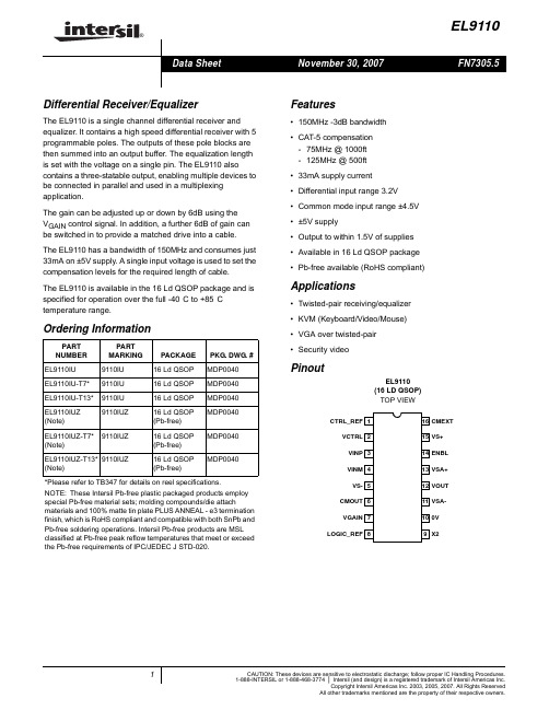
®EL9110Differential Receiver/EqualizerThe EL9110 is a single channel differential receiver and equalizer. It contains a high speed differential receiver with 5 programmable poles. The outputs of these pole blocks are then summed into an output buffer. The equalization length is set with the voltage on a single pin. The EL9110 also contains a three-statable output, enabling multiple devices to be connected in parallel and used in a multiplexing application.The gain can be adjusted up or down by 6dB using theV GAIN control signal. In addition, a further 6dB of gain can be switched in to provide a matched drive into a cable.The EL9110 has a bandwidth of 150MHz and consumes just 33mA on ±5V supply. A single input voltage is used to set the compensation levels for the required length of cable.The EL9110 is available in the 16 Ld QSOP package and is specified for operation over the full -40°C to +85°C temperature range.Features•150MHz -3dB bandwidth•CAT-5 compensation-75MHz @ 1000ft-125MHz @ 500ft•33mA supply current •Differential input range 3.2V •Common mode input range ±4.5V •±5V supply•Output to within 1.5V of supplies •Available in 16 Ld QSOP package •Pb-free available (RoHS compliant) Applications•Twisted-pair receiving/equalizer •KVM (Keyboard/Video/Mouse)•VGA over twisted-pair•Security videoPinoutEL9110(16 LD QSOP)TOP VIEWOrdering InformationPART NUMBERPARTMARKING PACKAGE PKG. DWG. #EL9110IU9110IU16 Ld QSOP MDP0040 EL9110IU-T7*9110IU16 Ld QSOP MDP0040 EL9110IU-T13*9110IU16 Ld QSOP MDP0040EL9110IUZ (Note)9110IUZ16 Ld QSOP(Pb-free)MDP0040EL9110IUZ-T7* (Note)9110IUZ16 Ld QSOP(Pb-free)MDP0040EL9110IUZ-T13* (Note)9110IUZ16 Ld QSOP(Pb-free)MDP0040*Please refer to TB347 for details on reel specifications.NOTE:These Intersil Pb-free plastic packaged products employ special Pb-free material sets; molding compounds/die attach materials and 100% matte tin plate PLUS ANNEAL - e3 termination finish, which is RoHS compliant and compatible with both SnPb and Pb-free soldering operations. Intersil Pb-free products are MSL classified at Pb-free peak reflow temperatures that meet or exceed the Pb-free requirements of IPC/JEDEC J STD-020.12341615141356712111089CTRL_REFVCTRLVINPVINMVS-CMOUTVGAINLOGIC_REFCMEXTVS+ENBLVSA+VOUTVSA-0VX2IMPORTANT NOTE:All parameters having Min/Max specifications are guaranteed. Typ values are for information purposes only. Unless otherwise noted, all tests are at the specified temperature and are pulsed tests, therefore: T J = T C = T AAbsolute Maximum Ratings (T A = +25°C)Thermal InformationSupply Voltage between V S + and V S -. . . . . . . . . . . . . . . . . . . . .12V Maximum Continuous Output Current. . . . . . . . . . . . . . . . . . . 30mA Pin Voltages. . . . . . . . . . . . . . . . . . . . . . . . . V S - -0.5V to V S + +0.5VPower Dissipation . . . . . . . . . . . . . . . . . . . . . . . . . . . . . See Curves Storage Temperature. . . . . . . . . . . . . . . . . . . . . . . .-65°C to +150°C Ambient Operating Temperature . . . . . . . . . . . . . . . .-40°C to +85°C Die Junction Temperature . . . . . . . . . . . . . . . . . . . . . . . . . . .+150°C Pb-free reflow profile . . . . . . . . . . . . . . . . . . . . . . . . . .see link below /pbfree/Pb-FreeReflow.aspCAUTION: Do not operate at or near the maximum ratings listed for extended periods of time. Exposure to such conditions may adversely impact product reliability and result in failures not covered by warranty.Electrical SpecificationsV SA + = V A + = +5V, V SA - = V A - = -5V, T A = +25°C, Unless Otherwise SpecifiedPARAMETER DESCRIPTIONCONDITIONSMIN (Note 1)TYPMAX (Note 1)UNITAC PERFORMANCE BW Bandwidth (See Figure 1)150MHz SR Slew RateV IN = -1V to +1V, V G = 0.35, V C = 0, R L = 75 + 75Ω 1.5V/ns THDTotal Harmonic Distortion10MHz 1V P-P out, V G = 0.35V, X2 gain, V C = 0-50dBcDC PERFORMANCE V OSOffset Voltage (bin #1)X2 gain, no equalization-250-10+250mV Offset Voltage (bin #2)CPI9049mVINPUT CHARACTERISTICS CMIR Common-mode Input Range Common-mode extension off -4/+3.5V CMIRx Extended CMIR Common-mode extension on±4.5V O NOISE Output NoiseV G = 0.35, X2 gain, 75 + 75Ω load, V C = 0.625mV RMS CMRR Common-mode Rejection Ratio Measured at 10kHz 60dB CMRR+Common-mode Rejection Ratio Measured at 10MHz 50dB CMBW CM Amplifier Bandwidth 10K || 10pF load 50MHz CM SLEW CM Slew RateMeasured @ +1V to -1V 100V/µs C INDIFF Differential Input Capacitance Capacitance V INP to V INM 600fF R INDIFF Differential Input Resistance Resistance V INP to V INM12.4M ΩC INCM CM Input Capacitance Capacitance V INP = V INM to ground 1.2pF R INCM CM Input Resistance Resistance V INP = V INM to ground 1 2.8M Ω+I IN Positive Input Current DC bias @ V INP = V INM = 0V 1µA -I IN Negative Input Current DC bias @ V INP = V INM = 0V1µA V INDIFFDifferential Input RangeV INP - V INM when slope gain falls to 0.92.53.2VOUTPUT CHARACTERISTICS V O Output Voltage Swing R L = 150Ω±3.5V I OUT Output Drive Current R L = 10Ω, V INP = 1V, V INM = 0V, X2 = gain, V G = 0.355060mA R OUTCM CM Output Resistance at 100kHz30ΩDiffGain Differential GainV C = 0, V G = 0.35, X2 = 5, R L = 75 + 75Ω0.85 1.01.1SUPPLY I SON Supply Current V ENBL = 5, V INM = 02738mA I SOFFSupply CurrentV ENBL = 0, V INM = 00.40.8mAPSRRPower Supply Rejection RatioDC to 100kHz, ±5V supply60dBLOGIC CONTROL PINS V HI Logic High Level V IN - V LOGIC ref for guaranteed high level 1.35V V LOW Logic Low Level V IN - V LOGIC ref for guaranteed low level 0.8V I LOGICH Logic High Input Current V IN = 5V, V LOGIC = 0V 50µA I LOGICL Logic Low Input CurrentV IN = 0V, V LOGIC = 0V15µANOTE:1.Parts are 100% tested at +25°C. Over-temperature limits established by characterization and are not production tested.Electrical SpecificationsV SA + = V A + = +5V, V SA - = V A - = -5V, T A = +25°C, Unless Otherwise Specified (Continued)PARAMETER DESCRIPTIONCONDITIONSMIN (Note 1)TYP MAX (Note 1)UNIT Pin DescriptionsPIN NUMBERPIN NAME PIN TYPE PIN FUNCTION1CTRL_REF Input Reference voltage for V GAIN and V CTRL pins 2VCTRL Input Control voltage (0 to 1V) to set equalization 3VINP Input Positive differential input 4VINM Input Negative differential input 5VS-Power -5V to core of chip6CMOUT Output Output of common mode voltage present at inputs 7VGAIN Input Control voltage to set overall gain (0V to 1V)8LOGIC_REFInput Reference voltage for all logic signals 9X2Logic InputLogic signal; low - gain = 1, high - gain = 2100V 0V reference for output voltage 11VSA-Power -5V to output buffer12VOUT Output Single-ended output voltage reference to pin 1013VSA+Power +5V to output buffer14ENBL Logic Input Logic signal to enable pin; low - disabled, high - enabled 15VS+Power +5V to core of chip16CMEXTLogic Input Logic signal to enable CM range extension; active highTypical Performance CurvesFIGURE 1.FREQUENCY RESPONSE FIGURE 2.TOTAL HARMONIC DISTORTIONFIGURE 3.RISE TIME FIGURE MON MODE REJECTIONFIGURE 5.CM AMPLIFIER BANDWIDTH FIGURE 6.PSRR vs FREQUENCY531-1-3-51M10M100M FREQUENCY (Hz)G A I N (d B )V GAIN = 0V V CTRL = 0V R LOAD = 150ΩX2 = OFF-40-45-50-55-60-650.1M1M 10M 100MFREQUENCY (Hz)T H D (d B c )V GAIN = 0V V CTRL = 0V V SS = +5V V EE = -5VR LOAD = 150ΩX2 = OFFINPUT = 0dBm2ns/DIV200mV/DIVV CTR = 0V V GAIN = 0.35V X2 = ON-20-40-60-80-100100k1M 10M 100MFREQUENCY (Hz)C M R R (d B c )420-2-4-6100k1M 10M 100MFREQUENCY (Hz)G A I N (d B )V GAIN = 0.35V V CTRL = 0V R LOAD = 150ΩX2 = ON-20-40-60-80-100-1201010k 10M 100MFREQUENCY (Hz)-P S R R (d B )100100k 1k 1M V EE = -5V V CTRL = 0V V GAIN = 0VINPUTS ON GNDFIGURE 7.PSRR vs FREQUENCYFIGURE 8.GAIN AS THE FUNCTION OF V CTRLFIGURE 9.GROUP DELAY AS THE FUNCTION OF THEFREQUENCY REPONSE CONTROL VOLTAGE (V CTRL )FIGURE 10.PACKAGE POWER DISSIPATION vs AMBIENTTEMPERATUREFIGURE 11.PACKAGE POWER DISSIPATION vs AMBIENT TEMPERATURETypical Performance Curves (Continued)0-20-40-60-80-1001010k10M100MFREQUENCY (Hz)+P S R R (d B )100100k1k1MV CC = 5V V CTRL = 0V V GAIN = 0VINPUTS ON GND10dB/DIV1MFREQUENCY (Hz)10M 100MG A I N (d B )100mV STEPV CTRL = 0mVV CTR = 800mV-20-100102030405060100mV STEPV CTRL = 0mVV CTRL = 900mV1M100M FREQUENCY (Hz)10M200M503010-10-30-50G R O U P D E L A Y (n s )10ns/DIV791mWθJA =158°C /WQ S O P 161.41.210.80.60.200255075100150AMBIENT TEMPERATURE (°C)P O W E R D I S S I P A T I O N (W )12585JEDEC JESD51-3 LOW EFFECTIVE THERMAL CONDUCTIVITY TEST BOARD0.41.116W θJA =112°C /WQ SO P 161.81.610.80.60.200255075100150AMBIENT TEMPERATURE (°C)P O W E R D I S S I P A T I O N (W )12585JEDEC JESD51-7 HIGH EFFECTIVE THERMAL CONDUCTIVITY TEST BOARD0.41.41.2Applications InformationLogic ControlThe EL9110 has three logical input pins, Chip Enable (ENBL), Common Mode Extend (CMEXT), and Switch Gain (X2). The logic circuits all have a nominal threshold of 1.1V above the potential of the logic reference pin. In most applications it is expected that this chip will run from a +5V, 0V, -5V supply system with logic being run between 0V and +5V. In this case the logic reference voltage should be tied to the 0V supply. If the logic is referenced to the -5V rail, then the logic reference should be connected to -5V. The logic reference pin sources about 60µA and this will rise to about 200µA if all inputs are true (positive).The logic inputs all source up to 10µA when they are held at the logic reference level. When taken positive, the inputs sink a current dependent on the high level, up to 50µA for a high level 5V above the reference level.The logic inputs, if not used, should be tied to the appropriate voltage in order to define their state.Control Reference and Signal ReferenceAnalog control voltages are required to set the equalizer and contrast levels. These signals are voltages in the range 0V to 1V, which are referenced to the control reference pin. It is expected that the control reference pin will be tied to 0V and the control voltage will vary from 0V to 1V. It is; however, acceptable to connect the control reference to any potential between -5V and 0V to which the control voltages are referenced.The control voltage pins themselves are high impedance. The control reference pin will source between 0µA and200µA depending on the control voltages being applied.The control reference and logic reference effectively remove the necessity for the 0V rail and operation from ±5V (or 0V and 10V) only is possible. However we still need a further reference to define the 0V level of the single ended output signal. The reference for the output signal is provided by the 0V pin. The output stage cannot pull fully up or down to either supply so it is important that the reference is positioned to allow full output swing. The 0V reference should be tied to a 'quiet ground' as any noise on this pin is transferred directly to the output. The 0V pin is a high impedance pin and draws dc bias currents of a few µA and similar levels of AC current.Common Mode ExtensionThe common mode extension circuitry extends the range of input common mode voltage before the input differential amplifier is overloaded. It does this by reducing the voltage equally at both inputs of the first differential amplifier as the common mode signal rises towards the supply. Similarly, when the common mode input signal goes low, the inputs to the first differential amplifier are raised whilst preserving the differential signal and maintain the amplifier within its common mode operating range.This operation may not always be desirable. A problem occurs because the EL9110 sinks or sources a common mode current though its input pins to create the common mode offset voltage. Assuming the system has been set up so that the differential line has a well-balanced impedance, then a problem will only occur when the common mode impedance to ground is not low. This will occur in systems where the inputs to the EL9110 are AC coupled. In such systems it is recommended that the common mode extension be disabled. In systems where the differential input signal is directly coupled and has its common mode level defined by a low impedance line driver, the common mode extension circuitry can extend the total common mode range by 2V to 3V.EqualizingWhen transmitting a signal across a twisted pair cable, it is found that the high frequency (above 1MHz) information is attenuated more significantly than the information at low frequencies. The attenuation is predominantly due to resistive skin effect losses and has a loss curve which depends on the resistivity of the conductor, surface condition of the wire and the wire diameter. For the range of high performance twisted pair cables based on 24awg copper wire (Cat 5 etc.) these parameters vary only a little between cable types, and in general cables exhibit the same frequency dependence of loss. (The lower loss cables can be compared with somewhat longer lengths of their more lossy brothers.) This enables a single equalizing law equation to be built into the EL9110.With a control voltage applied between pins 2 and 1, the frequency dependence of the equalization is shown in Figure8. The equalization matches the cable loss up to about 100MHz. Above this, system gain is rolled off rapidly to reduce noise bandwidth. The roll-off occurs more rapidly for higher control voltages, thus the system (cable + equalizer) bandwidth reduces as the cable length increases. This is desirable, as noise becomes an increasing issue as the equalization increases.The cable loss for 100m, 200m, and 300m of CAT 5 cable, based on manufacturer's loss curves is shown in Figure 14.Thus:•100m requires V C = 0.2V•200m requires V C = 0.6Vand:•300m requires V C = 1.0V approximatelyContrastBy varying the voltage between pins 7 and 1, the gain of the signal path can be changed in the ratio 4:1. The gain change varies almost linearly with control voltage. For normaloperation it is anticipated the X2 mode will be selected and the output load will be back matched. A unity gain to the output load will then be achieved with a gain control voltage of about 0.35V. This allows the gain to be trimmed up or down by 6dB to compensate for any gain/loss errors that affect the contrast of the video signal. Figure 12 shows an example plot of the gain to the load with gain control voltage.Circuit and Layout RecommendationThe interconnection cable is a transmission line therefore for proper function it should be treated like transmission line, a refection-free termination is necessary.A reflection-free termination is a real "ohmic" resistor with as less as possible reactive parasitic.The traces of the layout, up to the point where of thetermination resistor placed, are part of the transmission line which also includes the cable's connector. A connector with a better controlled impedance is an obligation for good picture quality. The termination resistor should be placed close to the inputs of the device's pins (pin 3 and pin 4.) The small capacitance differential and common modecapacitance of the input pins of the device makes it possible to connect parallel to the termination resistor.The cable will work as an antenna for all the RF spectrum which is "in the air" where the cable is used. The spectrum, particularly its common mode components, could and will contain high energy level of transients which are above the built-in protection level of the device and easily could damage its inputs. Using a transient protection circuit according to the given application is recommended. Since the used signal's bandwidth is in the range of 100MHz, for layout and power supply bypassing the roles of RF design should be applied.The following picture is taken from the DB9110 demo-board's layout. For better visibility the ground plain is removed.The ground plane is shown in Figure 14.0.8V GAIN0.41.02.01.81.41.00.60.4G A I N (V )0.60.21.61.20.8FIGURE 12.VARIATION OF GAIN WITH GAIN CONTROLVOLTAGE102030405060700.01M0.10M 1M10M 100MFREQUENCY (Hz)A T T E N U A T I O N (dB )FIGURE 13.CAT-5 CABLE ATTENUATION CHARACTERISTICS300M200M100M 50MThe accompanying circuit diagram is shown in Figure 15.Block Diagram12341615141356712111089CTRL_REFVCTRLVINPVINMVS-CMOUTVGAINLOGIC_REFCMEXTVS+ENBLVSA+VOUTVSA-0VX2R11330ΩC51µFR6R7R9R5C101µFR12330ΩC91µFC81nFC111nFC71µFC61nFTP7FIGURE 15.CIRCUIT DIAGRAMV S- & V SA- connected to -5VV S+ & V SA+ connected to +5VGAINASPCONTROLASP+BIASCIRCUITRYTypical ApplicationV CTRL0.1µF100-5V0.1µFCM OUT+5V0.1µF+5V-5V750.1µF+5V 12341615141356712111089CTRL_REFVCTRLVINPVINMVS-CMOUTVGAINLOGIC_REFCMEXTVS+ENBLVSA+VOUTVSA-0VX2All Intersil U.S. products are manufactured, assembled and tested utilizing ISO9000 quality systems.Intersil Corporation’s quality certifications can be viewed at /design/qualityIntersil products are sold by description only. Intersil Corporation reserves the right to make changes in circuit design, software and/or specifications at any time without notice. Accordingly, the reader is cautioned to verify that data sheets are current before placing orders. Information furnished by Intersil is believed to be accurate and reliable. However, no responsibility is assumed by Intersil or its subsidiaries for its use; nor for any infringements of patents or other rights of third parties which may result from its use. No license is granted by implication or otherwise under any patent or patent rights of Intersil or its subsidiaries.For information regarding Intersil Corporation and its products, see Quarter Size Outline Plastic Packages Family (QSOP)0.010C A BSEATING PLANE DETAIL XE E11(N/2)(N/2)+1NPIN #1I.D. MARKb0.004C cASEE DETAIL "X"A24°±4°GAUGE PLANE 0.010LA1DB HCeA0.007C A BL1MDP0040QUARTER SIZE OUTLINE PLASTIC PACKAGES FAMILYSYMBOL INCHESTOLERANCE NOTESQSOP16QSOP24QSOP28A 0.0680.0680.068Max.-A10.0060.0060.006±0.002-A20.0560.0560.056±0.004-b0.0100.0100.010±0.002-c 0.0080.0080.008±0.001-D 0.1930.3410.390±0.0041, 3E0.2360.2360.236±0.008-E10.1540.1540.154±0.0042, 3e 0.0250.0250.025Basic -L 0.0250.0250.025±0.009-L10.0410.0410.041Basic -N162428Reference-Rev. F 2/07NOTES:1.Plastic or metal protrusions of 0.006” maximum per side are not included.2.Plastic interlead protrusions of 0.010” maximum per side are not included.3.Dimensions “D” and “E1” are measured at Datum Plane “H”.4.Dimensioning and tolerancing per ASME Y14.5M-1994.。
欧真喷水织机系统集成电控使用说明书-V2.2

欧真喷水织机集成电控使用说明书(简易版)V2.2欧真自动化科技(上海)有限公司OG‐WS100喷水电控是集成化、一体化电控系统,可模块化配置电子卷取、电子送经、电子双送经,以及单喷、双喷电子储纬器。
系统核心采用高速ARM芯片,数字化管理各子系统,集成化程度高,实时控制能力强,并采用高精度编码器,精确同步和协调各系统工作,达到精准化控制。
系统电气优化布局,采用先进的电源管理技术,温升大大降低,同时使用的大量抑制电磁干扰和抗干扰措施,减小各系统间的电磁干扰,系统稳定性强。
系统采用统一的7寸彩色液晶屏,各子系统所有参数和设置都可以通过一个屏幕解决,简化了操作过程,提高了使用效率。
OG‐WS100集成化电控真正做到一体化、数字化、模块化,是一套稳定、可靠、高效的系统化产品。
一、 使用须知在使用之前,请您详细阅读本说明书,以确保正确使用本产品。
请将本说明书妥善保管,以便随时查阅。
1.在使用之前,请注意以下事项:输入电源:规格1:AC380V±15%, 50/60HZ;规格2:AC415V±15%, 50/60HZ;两种规格内部接线稍微不同。
请务必安全接地。
使用环境温度:0~45℃。
使用环境湿度:20~90%(无结露)存放环境温度:‐10~60℃。
存放环境湿度:20~90%(无结露)带慢速功能的电控,请按本说明书正确接入变频电源。
2.在使用时,请注意以下事项:通电状态,请勿打开电箱,请勿触摸电箱内部部件,以免烫伤或触电。
断电后5分钟内,请勿打开电箱,请勿触摸电箱内部部件,以免触电。
30分钟内请勿触摸带有发热标志的部件,以免烫伤。
非专业人员请勿擅自拆卸和维修电箱内部部件。
有故障无法排除或需要维修,请联系厂家。
二、 接口说明1.电箱布局(图2.1)说明:a)电子卷取伺服驱动器、电子送经1伺服驱动器和电子送经2伺服驱动器,根据需要进行配置,和当前图示可能有所不同。
b)图示为带变频慢速功能的电控,如无变频慢速功能,则接触器MSH及配套线束不安装。
- 1、下载文档前请自行甄别文档内容的完整性,平台不提供额外的编辑、内容补充、找答案等附加服务。
- 2、"仅部分预览"的文档,不可在线预览部分如存在完整性等问题,可反馈申请退款(可完整预览的文档不适用该条件!)。
- 3、如文档侵犯您的权益,请联系客服反馈,我们会尽快为您处理(人工客服工作时间:9:00-18:30)。
MIC
MIC
MIN MAX
1
2
3
4
5
6
1 电源开关 I 位置按下为打开电源,O 位置按下为关闭电源。
2 电源指示灯 打开电源时指示灯亮,关闭电源时指示灯不亮。
3 内置监听喇叭监听音量控制旋钮 顺时针旋转为增大音量,逆时针旋转为减小音量。
4 显示屏/触摸板 显示屏显示系统的所有信息动态,同时也是操作触摸屏。
USB
INTELLIGENT PUBLIC ADDRESS CENTRE OTE 9120
FULL ALARMING
EMERGENCY MIC
POWER
I O
MONITOR MIN MAX
MIC
MIC
MIN MAX
MODEL: CB-100
2
* 消防/公共广播系统
微型智能广播媒体矩阵系统
7 USB 接口
微型智能广播媒体矩阵
公共广播系统
OTE9120 OTE9140
PUBLIC ADDRESS DEVICE
USB
INTELLIGENT PUBLIC ADDRESS CENTRE OTE 9120
FULL ALARMING
EMERGENCY MIC
POWER
I O
MONITOR MIN MAX
MIC
MIC
13 分区 1-20 报警信号输入接口
输入来自消防中心的信号。
14 分区 21-40 报警信号输入接口(OTE9120 无该接口)
输入来自消防中心的信号。
15 内置收音的收音头模块
收音头模块,其详细说明请参照“收音模块连接说明”部分。
16 电话接口
IN 接口将电信通讯信号连接到本机器;OUT 接口链接其他电话机。
内部 MP3、内置 AM/FM、2 路电源、外部 4 种周边音源(CD、调谐器、卡座、MP3 节目播放器)。5 套定时方 案可方便切换。 3、八路普通音源输入,内置 MP3、AM/FM 收音,一路本机航空话筒输入(有第一优先功能),一路警报信号输 入(有第二优先功能),一路远程寻呼话筒信号输入(有第三级优先功能),四十路输出的大型音频矩阵。 4、 四十路消防紧急输入(短路信号),一路消防联动输出(短路信号,用于扩展,可连接警报发生器、时序电 源等)。(每一路紧急输入可以触发分区可编程,可以触发任意分区) 5、通过局域网接口能外接电脑通过软件对主机进行控制。(实现电脑远程设置定时、定点、定节目自动播发) (该项功能需另购远程控制软件方可实现)。 6、能通过 9 针口扩展远程寻呼话筒。 7、所有定时程序可随时简易的手动干预。 8、可实时监听各分区,带音量调节功能。(机械音量调节)。 9、采用 ARM9 平台,5.6 英寸彩屏+触摸板。 10、有 USB 接口,USB 口可将 U 盘的歌曲直接拷贝到主机里播放。 11、100 米范围无线遥控,有 12 个可编程按键,可定制一键打开/关闭分区,选音源,选曲等。 12、带 3 种钟声信号输出功能(机械音量调节)。 13、带警报信号输出功能(机械音量调节)。 14、带电话分区寻呼功能(机械音量调节,可修改密码、全区寻呼、自选寻呼、编组寻呼等功能)。 15、可定时控制外部音源的播放状态。 16、具有触摸屏触摸点校准功能。
2
* 消防/公共广播系统
外观功能介绍
微型智能广播媒体矩阵系统
6. 前面板说明
7
8
9
PUBLIC ADDRESS DEVICE
USB
INTELLIGENT PUBLIC ADDRESS CENTRE OTE 9120
FULL ALARMING
EMERGENCY MIC
POWER
I O
MONITOR MIN MAX
这些端子的操作需由经过指导的人员来6完6 成。
67
当意识到异常情况时
68
• 若电源线出现磨损或损坏,使用设备过程中声
音突然中断或因此而发出异常气味或冒烟时,请立 即断开电源,并请专业人员对设备进行检修。
操作处理注意事项 • 请勿将手指插入本设备的任何间隙或开口。 • 避免任何异物( 纸张、塑料或金属等) 插入或 落入本设备的任何间隙或开口,万一发生这种情 况,请立即断开电源。 • 请勿将身体压在本设备上,或在其上放置重物, 操作按钮、开关或连接机器时要避免过分用力。
本广播系统依据控制分区的数量,分为 OTE9120 和 OTE9140 两种机型,OTE9120 可控制 20 个分区; OTE9140 可控制 40 个分区。为用户提供了多种选择。
性能特点
1、集播放、智能定时控制、音频矩阵、分区控制、等功能于一身的公共广播控制器。 2、有 5 套定时方案,每套定时方案有 500 个定时点,按 7 天循环。每个定时点可控制分区的音源选择、钟声、
1
* 消防/公共广播系统
系统概述
微型智能广播媒体矩阵系统
微型智能广播媒体矩阵系统是集播放、智能定时控制、音频矩阵、分区控制、智能消防联动、远程电 脑控制、电话寻呼和远程寻呼等功能于一身的智能化公共广播系统。
本广播系统以其完整的公共广播功能和人性化的智能控制功能,更适用于中小型广播系统用户的需求。 如:中小学校园,中小型ห้องสมุดไป่ตู้厂、公园、广场等公共场合的广播扩声。
电源/电源线
39
• 拔出电源线插头时,请抓住插头而不40是电源线。
直接拽拉电源线可能会导致损坏。 41
• 请勿将电源线放在热源附近。不要过42分弯折电
源线,不要将其放在可能被踩踏或引起4绊3 倒的地
方。
44
• 本设备是通过电源线插头和电网电源45连接,当 设备发生故障或危险时,拔出电源线插4头6 即可断开
设备与电网的连接,故要求将电源插座4置7 于可方便
进行电源线拔插操作的地方。
48
• 本设备的电源开关在“关”状态时,49机器并未
与电网断开,为安全起见,在不使用本5设0 备时请将
电源线插头拔出电网插座。
51
52
安放位置
53
• 移动本设备之前,请断开电源。 54
• 为了避免面板发生变形或损坏内部组55件,请勿
MIN MAX
TUNER OUT
FM(75Ω)
GND AM
ANTENNA
TEL
IN
OUT
TUNER IN
NET
DATA OUT (MP88/99)
TIMING OUTLET
PWR 1 (~220V/50Hz/500W) PWR 2 (~220V/50Hz/500W)
~AC IN F1AL250V
F10AL250V
2 四十个音频矩阵输出接口(OTE9120 为 20 个) 每个音频输出接口对应一个分区,连接该分区功放的音频输入接口。
3 内置收音音量调节旋钮 用该旋钮可以机械调节内置收音的音量大小。
4 内置 MP3 音量调节旋钮 用该旋钮可以机械调节内置 MP3 的音量大小。
5 电话寻呼音量调节旋钮 用来调节电话寻呼的输出音量大小。
MIN MAX
使用说明书
欢迎使用迪士普播系统。为了您能更好的使用本设备,使用前请仔细阅读本说明书。
广州市迪士普音响科技有限公司
说明书信息提示
本说明书包含了微型智能广播媒体矩阵系统 OTE9120 和 OTE9140 两个型号机型的内 容,包括产品功能介绍、外观介绍、连接图例、设置操作、使用说明、安全注意事项、售后 服务事宜及产品的性能规格等,在连接使用前务必详细阅读本说明书。
6 钟声音量调节旋钮 用来调节内置钟声输出的音量大小。
7 外设警报信号输入接口 1
3
* 消防/公共广播系统
微型智能广播媒体矩阵系统
可连接警报发生器,将其警报信号输入到本机器中,自动打开对应的分区进行报警。该接口的信号具有 二级优先功能,其优先级仅次于前面板上的航空话筒。
8 报警音量调节旋钮
用来调节警报发生器输入的报警信号的音量大小。
9 无线遥控接收天线接口
将无线遥控天线连接与该接口。详细介绍请参阅“无线遥控功能说明”部分。
10 远程寻呼器连接口
9 针 D 型数据串口,可直接连接远程寻呼器设备,也可连接寻呼集线器以扩展多个远程寻呼器。
11 远程寻呼器音量调节旋钮
可机械调节远程寻呼器的音量大小。
12 短路信号输出接口
输出短路信号给其他需要激活的设备。
用来连接存储有 MP3 节目的 U 盘,移动硬盘等存储器设备,为内置的 MP3 播放器拷贝节目,也可插 带有 USB 插头的鼠标。
8 全告警按键
系统全告警按钮,按下该按钮可同时对所有分区发送报警信号。正在发送报警信号时按钮灯亮,按一次 按钮,关闭报警时按钮灯不亮,且按键弹起。
9 话筒挂扣
在不使用话筒时,将话筒背部的挂纽放进该孔内。
将本设备放在有大量灰尘、震动、极端5寒6 冷或炎热
的环境中。
57
• 本设备不能遭受水滴或水溅,且不能58将装满水
的花瓶之类的物品放置在设备上。 59
60
连接
61
• 将本设备连接到其它设备之前,请先62将这些设
备的电源断开。在打开或关闭设备的电6源3 开关之
前,请将所有音量都调到最小。
64
• 设备中标有 符号的端子表示危险6带5电,连接
ZONE 8
TUNER TEL ZONE 9 ZONE 10
ZONE 11 ZONE 12 ZONE 13 ZONE 14 ZONE 15 ZONE 16 ZONE 17 ZONE 18 ZONE 19 ZONE 20 ZONE 21 ZONE 22 ZONE 23 ZONE 24 ZONE 25 ZONE 26 ZONE 27 ZONE 28 ZONE 29 ZONE 30
ZONE 31 ZONE 32 ZONE 33 ZONE 34 ZONE 35 ZONE 36 ZONE 37 ZONE 38 ZONE 39 ZONE 40
