AP-MK7-0024-V1.0-mk7a23 adc[1]
韩国凯昆KACON蜂鸣器大全

讯响器&蜂鸣器&程控语音警报器&电铃
HRB 系列带LED灯蜂鸣器
9
10
HRB-PS □ □ □ □
安装尺寸
52: Ф25mm
额定电压
D12: AC/DC12V;
5声0音: 类Ф型30mm I : 间断音
产品特点
➢带超高亮LED电子式蜂鸣器。 ➢Ф25mm/Ф30mm两种安装尺寸。 ➢可选间断音和连续音,两种音型。 ➢耐长时间工作,无电磁干扰和抗干
性形式之一)。
➢耐长时间工作、电气寿命长、温升稳定。
➢悦耳的音质,新颖的式样,已获得实用新型专利。
➢具有表面安装型(N80)和面板埋入安装型(P80)。
➢升级版产品→ 电子式,开关电源降压驱动。
适用于KSP-6系列、KSP-4系列、
带LED工作状态指示灯(间断闪亮)。
KSP-8系列、KMB-P80系列进行表
讯响器&蜂鸣器&程控语音警报器&电铃
K16 系列蜂鸣器
13
14
NEW
15
16
齐平型仅圆形,附件另售。
产品特点
➢Ф16mm用微型电子式蜂鸣器。 ➢具有圆形和长方形,带LED指示灯声
光报警型。 ➢具有齐平安装型,铝合金安装圈,
露出面板仅2mm。 ➢获得CE, UL, c-UL, CCC认证。 ➢可选连续音和间断音。
讯响器&蜂鸣器&程控语音警报器&电铃
1
2
3
4
KSP-61S KSP-62S 5
KSP-61L KSP-62L 6
KSP-41S KSP-41T K7SP-42S KSP-42T
Bracket 安装支架 8
MK7-3型阻拦装置定长冲跑控制阀结构特点及控制规律

MK7-3型阻拦装置定长冲跑控制阀结构特点及控制规律MK7-3型阻拦装置定长冲跑控制阀是一种用于飞机起落架的阻拦装置,它主要可完成飞机起落架的抬起和放下,并且可以精确控制飞机行进的力度和速度。
其结构特点和控制规律如下。
1. 结构特点MK7-3型阻拦装置定长冲跑控制阀采用的是液压控制系统,主要由定长冲跑控制阀、三通阀、单向阀、减压阀、液压缸与液压泵组成。
定长冲跑控制阀具有精密密封性,通过开关控制,可以实现准确的冲跑长度和速度控制。
在起落架抬升时,阀门关闭隐藏在机体内部,从而防止起落架掉落。
当起落架降落到一定高度时,阀门会打开,从而实现起落架下降。
三通阀的作用是控制液压泵的流向,从而控制液压油向上油缸和下油缸的流动方向。
单向阀可防止液压油倒回液压泵,从而保证环路的稳定性。
减压阀可根据系统的压力,调节起落架上下的力度和速度,从而保证起落架的安全性。
液压缸是起落架的主要载荷,它能够承受飞机起飞和降落时的大荷载,并提供足够的支撑力。
液压泵是装置的动力源,它通过内部的液压传动系统,来为整个装置提供足够的液压动力。
2. 控制规律MK7-3型阻拦装置定长冲跑控制阀的控制规律主要是通过周期性开关来实现的。
在起落架运动过程中,控制阀的开启和关闭决定了起落架的运动速度和力度。
开关的控制信号是通过飞机上的电路系统来控制的。
在起落过程中,控制阀的关闭可以阻止起落架下降,从而确保起落架的稳定性。
当飞机降落时,控制阀会打开,以保证起落架的缓慢下降,从而避免起落架的损坏。
同时,控制阀的周期性开关还可以调节起落架上下的力度和速度,从而使起落架运动更加稳定流畅,确保飞机起飞和降落的安全性。
综上所述,MK7-3型阻拦装置定长冲跑控制阀具有结构紧凑、性能优良、控制灵活、可靠性高等特点,它在飞机起落架的控制方面发挥着关键作用。
通过不断的技术创新和优化,该装置的性能和安全性将不断提高,为飞机的起降提供更加稳定可靠的保障。
相关数据是在研究或者实践中获取的关于某些现象或者事件的数据。
MK7A23P,MK7A25P,MK6A12P,MK9A35P,MK9A50P,MK6A20P
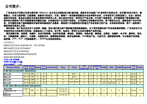
公司简介:广州龙启电子有限公司是台湾芯睿(Mikkon)总公司正式授权的大陆A级代理,是较早在内地推广MK系列单片机的公司。
在芯睿8位单片机中,规模最大、开发力度和推广力度最强;是集单片机设计、开发、销售于一体的新型高新技术企业和软件企业,公司设有专门的研发部门,以及一系列先进的开发设备,配备多名极具专业高水准的开发研究人员,现已成功开发出一系列电子产品方案,可为客户直接采用,并可根据客户要求提供方案、软件设计或按客户的不同意愿增加和删改功能,以体现出客户自身的产品特色。
公司坚持以市场需求为导向,客户需求为己任,视每位客户为合作伙伴,尽可能的为客户提供最新的市场咨询和最佳的产品服务,帮助客户以创新的技术快速生产出有竞争力的产品,以争取和供应商、客户一起取得三赢的局面为追求之目标。
我们信奉:客户是企业生存下去的唯一根源。
因此,我们将为客户提供最完善的配套服务。
为了更好的满足客户和市场发展的需要,广州龙启电子公司逐步向多元化经营方向发展,快速地切入了小家电、电子秤、电动车、草坪灯以及其它数码产品的市场。
现有成熟方案:电饭煲、电磁炉、电动车控制器、电动车防盗器、游戏机、消毒柜、电热水器、咖啡壶、豆浆机、电磁炉、电子秤、搅拌机、面包机、万能遥控器、感应大、小便器、无线麦克风、按摩浴缸控制器、家用电器控制、USB周边产品、卫星开关、遥控器系列等。
可以提供开发系统,烧录器,OTP、QTP(代客烧程序)、MASK以及相应的样品。
同资源型号:MK6A12P管脚兼容EM78P153、PIC12F508MK7A25P管脚兼容HT46R47MKA23P管脚兼容S3F9454MK8A03P-EM78P680/HT82A523RMK9A35P-EM78P468开发工具:仿真器 RMB1200(除LCD型号外全通用) LCD型号上板 RMB600 烧写器 RMB350MK9A80P <MK9A80P AP Note> MK8A03BP 8K*16192B 840X X X X V V X X X V 48 pin P以上产品均提供O TP DICE 郭秀莉Sally Guo广州市龙启电子有限公司Tel :139******** Fax :0755-******** 020-********Mobile:深圳015816858482/ 广州188********Email:xiuli122@ 、longqiguo@Add:广州市越秀区寺右南一街一巷9号广日大厦506室 /深圳岗厦福田彩田路彩天名苑红荔轩15F 贸易通:gzlqdzmcu QQ:137990408 Skype :longqiguo8K*161088B 839+1*8comx50seg 1/2,1/3,1/4,1/5,1/6,1/7,1/8X 76 pin X X X V USB Controller DatasheetsX X X X。
Motorola 3.5 kHz 产品说明书

RVN4126 3.59100-386-9100-386/T DEVICERVN41772-CD2-3.5MCS/MTSRVN41821-CD2-3.5XTS3000/SABER PORTABLE YES RKN4046KHVN9085 3.51-20 R NO HLN9359 PROG. STAND RVN4057 3.532 X 8 CODEPLUG NO3080385B23 & 5880385B30 MDVN4965 3.59100-WS/T CONFIG KITRVN4053 3.5ASTRO DIGITAL INTERFACE NO3080385B23RVN41842-CD RKN4046A (Portable) 2-3.5ASTRO PORTABLE /MOBILE YES3080369B73 or0180300B10 (Mobile) RVN41831-CD3080369B732-3.5ASTRO SPECTRA MOBILE YES(Low / Mid Power)0180300B10 (High Power) RVN4185CD ASTRO SPECTRA PLUS MOBILE NO MANY OPTIONS; SEESERVICE BRIEF#SB-MO-0101RVN4186CD ASTRO SPECTRA PLUS MANY OPTIONS;MOBILE/PORTABLE COMB SEE SERVICE BRIEF#SB-MO-0101RVN4154 3.5ASTROTAC 3000 COMPAR.3080385B23RVN5003 3.5ASTROTAC COMPARATORS NO3080399E31 Adpt.5880385B34RVN4083 3.5BSC II NO FKN5836ARVN4171 3.5C200RVN4029 3.5CENTRACOM SERIES II NO VARIOUS-SEE MANUAL6881121E49RVN4112 3.5COMMAND PLUS NORVN4149 3.5COMTEGRA YES3082056X02HVN6053CD CT250, 450, 450LS YES AAPMKN4004RVN4079 3.5DESKTRAC CONVENTIONAL YES3080070N01RVN4093 3.5DESKTRAC TRUNKED YES3080070N01RVN4091 3.5DGT 9000 DESKSET YES0180358A22RVN4114 3.5GLOBAL POSITIONING SYS.NO RKN4021AHVN8177 3.5GM/GR300/GR500/GR400M10/M120/130YES3080070N01RVN4159 3.5GP60 SERIES YES PMLN4074AHVN9128 3.5GP300 & GP350RVN4152 3.5GP350 AVSRVN4150 3.5GTX YES HKN9857 (Portable)3080070N01(Mobile) HVN9025CD HT CDM/MTX/EX SERIES YES AARKN4083/AARKN4081RiblessAARKN4075RIBLESS NON-USA RKN4074RVN4098H 3.5HT1000/JT1000-VISAR YES3080371E46(VISAR CONV)RVN4151 3.5HT1000 AVSRVN4098 3.5HT1000/ VISAR CONV’L.YES RKN4035B (HT1000) HVN9084 3.5i750YES HLN-9102ARVN4156 3.5LCS/LTS 2000YES HKN9857(Portable)3080070N01(Mobile) RVN4087 3.5LORAN C LOC. RECV’R.NO RKN4021ARVN4135 3.5M100/M200,M110,M400,R100 includesHVN9173,9177,9646,9774YES3080070N01RVN4023 3.5MARATRAC YES3080070N01RVN4019 3.5MAXTRAC CONVENTIONAL YES3080070N01RVN4139 3.5MAXTRAC LS YES3080070N01RVN4043 3.5MAXTRAC TRK DUPLEX YES3080070N01RVN4178CD MC SERIES, MC2000/2500DDN6124AW/DB25 CONNECTORDDN6367AW/DB9 CONNECTOR RVN41751-CD Rib to MIC connector 1-3.5MCS2000 RKN4062BRVN41131-3.5MCS2000RVN4011 3.5MCX1000YES3000056M01RVN4063 3.5MCX1000 MARINE YES3000056M01RVN4117 3.5MDC/RDLAP DEVICESRVN4105 3.5MOBILE PROG. TOOLRVN4119 3.5MOBITEX DEVICESRVN4128 3.5MPT1327-1200 SERIES YES SEE MANUALRVN4025 3.5MSF5000/PURC/ANALOG YES0180355A30RVN4077 3.5MSF5000/10000FLD YES0180355A30RVN4017K 3.5MT 1000YES RTK4205CRVN4148 3.5MTR 2000YES3082056X02RVN4140 3.5MTRI 2000NORVN41761-CD MTS2000, MT2000*, MTX8000, MTX90001-3.5*programmed by DOS which is included in the RVN4176RVN4131 3.5MTVA CODE PLUG FIXRVN4142 3.5MTVA DOCTOR YES3080070N01RVN4131 3.5MTVA3.EXERVN4013 3.5MTX800 & MTX800S YES RTK4205CRVN4097 1-CD MTX8000/MTX9000,MTS2000,MT2000*,* programmed by DOS which is included in the RVN4176HVN9067CD MTX850/MTX8250MTX950,MTX925RVN4138 3.5MTX-LS YES RKN4035DRVN4035 3.5MX 1000YES RTK4203CRVN4073 3.5MX 800YES RKN4006BHVN9395 P100, P200 LB, P50+, P210, P500, PR3000RVN4134 3.5P100 (HVN9175)P200 LB (HVN9794)P50+ (HVN9395)P210 (HVN9763)P500 (HVN9941)PR3000 (HVN9586)YES RTK4205HVN9852 3.5P110YES HKN9755A/REX1143 HVN9262 3.5P200 UHF/VHF YES RTK4205RVN4129 3.5PDT220YVN4051 3.5PORTABLE REPEATER Portable rptr.P1820/P1821AXRVN4061C 3.5PP 1000/500NO3080385B23 & 5880385B30 RVN5002 3.5QUANTAR/QUANTRO NO3O80369E31RVN4135 3.5R100 (HVN9177)M100/M200/M110/M400YES0180358A52RVN4146 3.5RPM500/660RVN4002 3.5SABER YES RTK4203CRVN4131 3.5SETTLET.EXEHVN9007 3.5SM50 & SM120YESRVN4039 3.5SMART STATUS YES FKN5825AHVN9054 3.5SOFTWARE R03.2 P1225YES3080070N01HVN9001 3.5SOFTWARE R05.00.00 1225LS YES HLN9359AHVN9012 3.5SP50RVN4001N 3.5SPECTRA YES3080369B73 (STANDARD)0180300B10 (HIGH POWER) RVN4099 3.5SPECTRA RAILROAD YES3080369B73RVN4110 3.5STATION ACCESS MODULE NO3080369E31RVN4089A 3.5STX TRANSIT YES0180357A54RVN4051 3.5SYSTEMS SABER YES RTK4203BRVN4075 3.5T5600/T5620 SERIES NO3080385B23HVN9060CD TC3000, TS3000, TR3000RVN4123 3.5VISAR PRIVACY PLUS YES3080371E46FVN4333 3.5VRM 100 TOOLBOX FKN4486A CABLE &ADAPTORRVN4133 3.5VRM 500/600/650/850NORVN4181CD XTS 2500/5000 PORTABLES RKN4105A/RKN4106A RVN41002- 3.5XTS3000 ASTRO PORTABLE/MOBILERVN4170 3.5XTS3500YES RKN4035DRIB SET UPRLN4008E RADIO INTERFACE BOX (RIB)0180357A57RIB AC POWER PACK 120V0180358A56RIB AC POWER PACK 220V3080369B71IBM TO RIB CABLE (25 PIN) (USE WITH XT & PS2)3080369B72IBM TO RIB CABLE (9 PIN)RLN443825 PIN (F) TO 9 PIN (M) ADAPTOR (USE W/3080369B72 FOR AT APPLICATION) 5880385B308 PIN MODULAR TO 25 PIN ”D” ADAPTOR (FOR T5600 ONLY)0180359A29DUPLEX ADAPTOR (MOSTAR/TRAXAR TRNK’D ONLY)Item Disk Radio RIB Cable Number Size Product Required Number Item Disk Radio RIB Cable Number Size Product Required NumberUtilizing your personal computer, Radio Service Software (RSS)/Customer Programming Software (CPS)/CustomerConfiguration Software (CCS) enables you to add or reprogram features/parameters as your requirements change. RSS/CPS/CCS is compatible with IBM XT, AT, PS/2 models 30, 50, 60 and 80.Requires 640K RAM. DOS 3.1 or later. Consult the RSS users guide for the computer configuration and DOS requirements. (ForHT1000, MT/MTS2000, MTX838/8000/9000, Visar and some newer products —IBM model 386, 4 MEG RAM and DOS 5.0 or higher are recommended.) A Radio Interface Box (RIB) may be required as well as the appropriate cables. The RIB and cables must be ordered separately.Licensing:A license is required before a software (RVN) order is placed. The software license is site specific (customer number and ultimate destination tag). All sites/locations must purchase their own software.Be sure to place subsequent orders using the original customer number and ship-to-tag or other licensed sites; ordering software without a licensed customer number and ultimate tag may result in unnecessary delays. To obtain a no charge license agreement kit, order RPX4719. To place an order in the U.S. call 1-800-422-4210. Outside the U.S., FAX 847-576-3023.Subscription Program:The purchase of Radio ServiceSoftware/Customer Programming/Customer ConfigurationSoftware (RVN & HVN kits) entitles the buyer/subscriber to three years of free upgrades. At the end of these three years, the sub-scriber must purchase the same Radio Service Software kit to receive an additional three years of free upgrades. If the sub-scriber does not elect to purchase the same Radio Service Software kit, no upgrades will be sent. Annually a subscription status report is mailed to inform subscribers of the RSS/CPS/CCS items on our database and their expiration dates.Notes:1)A subscription service is offered on “RVN”-Radio Service Software/Customer Programming/Customer Configuration Software kits only.2)“RVN” software must only be procured through Radio Products and Services Division (RPSD). Software not procured through the RPSD will not be recorded on the subscription database; upgrades will not be mailed.3)Upgrades are mailed to the original buyer (customer number & ultimate tag).4)SP software is available through the radio product groups.The Motorola General Radio Service Software Agreement is now available on Motorola Online. If you need assistance please feel free to submit a “Contact Us” or call 800-422-4210.SMART RIB SET UPRLN1015D SMART RIB0180302E27 AC POWER PACK 120V 2580373E86 AC POWER PACK 220V3080390B49SMARTRIB CABLE (9 PIN (F) TO 9 PIN (M) (USE WITH AT)3080390B48SMARTRIB CABLE (25 PIN (F) TO 9 PIN (M) (USE WITH XT)RLN4488ASMART RIB BATTERY PACKWIRELESS DATA GROUP PRODUTS SOFTWARERVN4126 3.59100-386/9100T DEVICES MDVN4965 3.59100-WS/T CONFIG’TN RVN41173.5MDC/RDLAP DEVICESPAGING PRODUCTS MANUALS6881011B54 3.5ADVISOR6881029B90 3.5ADVISOR ELITE 6881023B20 3.5ADVISOR GOLD 6881020B35 3.5ADVISOR PRO FLX 6881032B30 3.5BR8506881032B30 3.5LS3506881032B30 3.5LS5506881032B30 3.5LS7506881033B10 3.5LS9506881035B20 3.5MINITOR III8262947A15 3.5PAGEWRITER 20008262947A15 3.5PAGEWRITER 2000X 6881028B10 3.5TALKABOUT T3406881029B35 3.5TIMEPORT P7308262947A15 3.5TIMEPORT P930NLN3548BUNIVERSAL INTERFACE KITItem Disk Radio NumberSize Product。
芯睿MK单片机各类型号常用选型表(最新版)
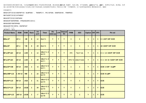
MK9A35EP-LCD 3.5K*16 96B 8
20
16bit*2/8 bit*3
V
V
V
X
X
V
X V DICE/64LQFP
MK9A50P-LCD 5K*16 192B 8
31
16bit*2/8 bit*3
V
V
V
V
X
V
X V DICE
MK9A81P-LCD 8K*16 1088B 8
39
16bit*3/8 bit*3
MK6A20P-PIC16F54、EM78P447 开发工具:仿真
器1200元,烧录
Product Name
ROM
RAM Stack
I/O port
Timer
Pin wake-up
LVR
Internal RC
PWM
ADC
Capture SPI RFC
Pin out
MK6A12P
1K*14 48B 6
、各类控制板、USB相关产品等在市
备注 8 位倒计时定时器/计数器 带自动重复加载功能 替代EM78P447,无中断
USB 2.0 and USB1.1 full speed/SPI serial communication LCD Driver:7comx27seg 1/4,1/5,1/6 ,1/7 LCD Driver:8comx42seg 1/4,1/5,1/6 ,1/7,1/8 LCD Driver: 8comx50seg 1/2,1/3,1/4 ,1/5,1/6,1/7,1/8 LCD Driver: 16comx64seg 1/2,1/3,1/4 ,1/5,1/6,1/7,1/8,1/10,1 /12,1/16
位(11bit 4bit)AD
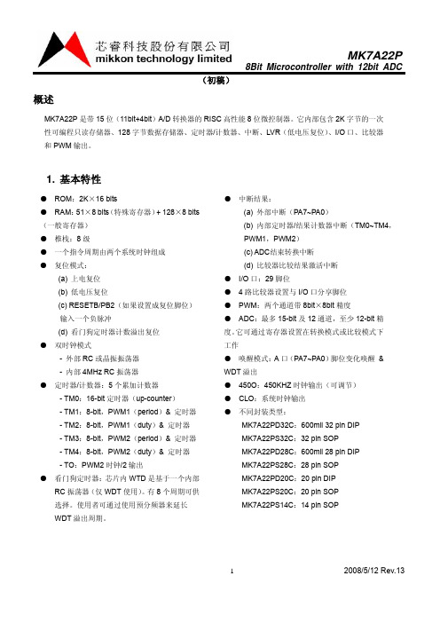
8Bit Microcontroller with 12bit ADC(初稿)12008/5/12 Rev.13概述MK7A22P 是带15位(11bit+4bit )A/D 转换器的RISC 高性能8位微控制器。
它内部包含2K 字节的一次性可编程只读存储器、128字节数据存储器、定时器/计数器、中断、LVR (低电压复位)、I/O 口、比较器和PWM 输出。
1. 基本特性● ROM :2K ×16 bits● RAM :51×8 bits (特殊寄存器)+ 128×8 bits (一般寄存器) ● 椎栈:8级● 一个指令周期由两个系统时钟组成 ● 复位模式:(a) 上电复位 (b) 低电压复位(c) RESETB/PB2(如果设置成复位脚位)输入一个负脉冲(d) 看门狗定时器计数溢出复位 ● 双时钟模式- 外部RC 或晶振振荡器 - 内部4MHz RC 振荡器 ● 定时器/计数器:5个累加计数器- TM0:16-bit 定时器(up-counter ) - TM1:8-bit ,PWM1(period )& 定时器 - TM2:8-bit ,PWM1(duty )& 定时器 - TM3:8-bit ,PWM2(period )& 定时器 - TM4:8-bit ,PWM2(duty )& 定时器 - TO :PWM2时钟/2输出● 看门狗定时器:芯片内WTD 是基于一个内部RC 振荡器(仅WDT 使用)。
有8个周期可供选择。
使用者可通过使用预分频器来延长WDT 溢出周期。
● 中断结果:(a) 外部中断(PA7~PA0)(b) 内部定时器/结果计数器中断(TM0~TM4,PWM1,PWM2) (c) ADC 结束转换中断 (d) 比较器比较结果激活中断 ● I/O 口:29脚位● 4路比较器设置与I/O 口分享脚位 ● PWM :两个通道带8bit ×8bit 精度● ADC :最多15-bit 及12通道,至少12-bit 精度。
MK7-3型拦阻装置滑轮运动特性分析
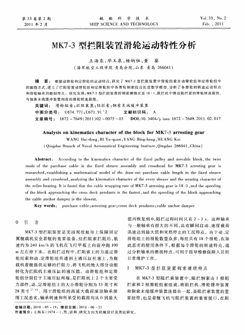
Absr c t a t:
Ac o d n o t e i e ai s c a a t r o h ie ul y a d m o a l b o k,te wit c r i g t h k n m tc h r ce f t e fx d p l n v b e lc e h t s
和 滑 轮 轴 承 的 磨 损 特 点 。研 究 发 现 : 73型 拦 阻 装 置 的 钢 索 缠 绕 比是 1 1 阻拦 机 中靠 近 阻拦 索 的 滑 轮转 速最 快 , MK — 8: ,
与钢 索末 端 缓 冲 装 置 相 连 词 : 滑轮 组 索 ; 阻 装 置 ; 拦 阻拦 索 ; 索 末 端 缓 冲 装 置 钢 中 图 分 类 号 : U 7 .7 ; 6 1 9 2 647 1 U 7 .1 文献 标识 码 : A
mo e o t e u c a e a l i t e ix d h a e s e l a c o s e d o M K7— a r sig e r s d f h p r h s c b e n h f e s e v a s mb y nd r s h a f r 3 re tn g a i rs a c d, sa ls n ah ma ia o e f t e drw— u u c s c bl lngh n h x d h a e e e r he e t b ihi g a m t e t lm d lo h a o t p r ha e a e e t i t e f e s e v c i a s m by a d c o s e d, n l zn he k n m ai sc r c e ft e e e y s e v nd t e we rn ha a t ro s e l n r s h a a ay i gt i e tc ha a tro h v r h a e a h a i g c r c e f t e r le e rng I i o n h tt e c b ewr p i g r t fM K7— re tn e ri : a d t p e i g h o lrb a i . t sf u d t a h a l a p n ae o 3 a r si g g a s1 1, n he s e d n 8 o h o k a p o c i g t e c o s d c e d n s i h a t s , n h p e i g o he b o k a p o c n ft e blc p r a h n h r s e k p n a t s t e fse t a d t e s e d n ft l c p r a hig t e c be a h rd mpe s t e so s . h a l nc o a ri h lwe t K e r s: y wo d pu c a e c b e; re t g g a ; R S e k p n a s c b e a c o a p r r h s a l a r si e r C O S d c e d nt ; a l n h r d m e n
指令集说明
mikkon technology limited
Veห้องสมุดไป่ตู้1.2
2006 年 10 月 25 日
Application
Note
AP-MK7-00001
8. 清零测试 格式: BTSC M, bn 操作: 当M的第n位为0时, 跳过下一条指令 影响状态位: 无 指令周期: 1 + (skip) 例:NOW: BTSC flag,b0 FALSE: LGOTO PROCESS TURE: ………… ………………… 指令执行前 PC=address(NOW) 指令执行后 if flag<b0>=0 PC= address(TURE) if flag<b0>=1 PC= address(FALSE) 9. 置位测试 格式: BTSS M, bn 操作: 当M的第n位为1时, 跳过下一条指令 影响状态位: 无 指令周期: 1 + (skip) 例: NOW: BTSS flag,b0 FALSE: LGOTO PROCESS TURE: ………… ………………… 指令执行前 PC=address(NOW) 指令执行后 if flag<b0>=1 PC= address(TURE) if flag<b0>=0 PC= address(FALSE) 10. 清 A 寄存器 格式: CLRA 操作: 清A寄存器 影响状态位:Z 指令周期:1 例: CLRA 指令执行前 A=68H 指令执行后 A=00H 11. 清寄存器 格式: CLR M 操作: 清M寄存器 影响状态位:Z 指令周期:1 第3页
mikkon technology limited
Ver1.2
2006 年 10 月 25 日
交流220 V同步方式通信电路的灯光控制系统

交流220 V同步方式通信电路的灯光控制系统引言直流电的三线控制方式由于线路简单、成本低,广泛用于各种照明系统的控制场合[1,2],但交流系统中无法提供稳定的参考点[3],实际应用中通常使用电力线载波通信方式或无线通信方式进行控制,因此存在电路复杂、可靠性低、待机功耗较大、维护难等问题[4]。
为此,本文提出与交流电50 Hz同步方式工作的教室灯光控制系统,这种电路采用三线工作方式,分别为2根220 V交流电源线和一根公用信号线,主机和分机只通过一根公用信号线传送信号。
1 通信电路工作原理设计交流220V同步方式工作的通信电路由一个主机和N个分机组成,可进行双向通信,主机呼叫分机后发送各种操作命令,分机响应后发送本机的状态。
1.1 主机和分机的参考点设计图1为主机和分机之间形成参考地的电路示意图。
山西省日前创新市场化机制,引入中交疏浚(集团)股份有限公司作为战略投资方,组建汾河流域投资公司,统筹项目资金,以市场化方式满足工程建设需求,对汾河进行全流域系统治理。
图1 参考地的形成电路Fig.1 Ground formation circuitR0为线路的等效电阻,R1和R2保证交流电的整个周期中整流桥D1、D2始终处于微导通状态。
当正半周时L线为正极性N线为负极性,整流桥D1的D11、D13导通,整流桥D2的D21、D23导通,A点经过D13、R0、D23连接到B点,当负半周时L线为负极性N线为正极性,整流桥D1的D12、D14导通,整流桥D2的D22、D24导通,A点经过D14、R0、D24连接到B点。
因此不管是正半周还是负半周A点与B点之间的电压UAB取决于式(1),式中i为线上的交流电流,UD为整流桥中每个二极管的正向压降。
UBA=|iR0+UD|-UD=|iR0|(1)可知整流桥D1、D2导通时压降互相抵消。
由于每个集中控制区的线路电阻较小,电流分布也是离散方式,因此最远的2个装置之间的电压UBA可以控制在30 V以内。
安培克 APW7302B 2A 24V 340kHz 同步降压转换器 数据手册说明书

ANPEC reserves the right to make changes to improve reliability or manufacturability without notice, and advise customers to obtain the latest version of relevant information to verify before placing orders.FeaturesGeneral Description•Wide Input Voltage from 4.5V to 24V •2A Continuous Output Current•Adjustable Output Voltage from 0.92V to 20V •Intergrated N-MOSFET•Fixed 340kHz Switching Frequency •PFM/PWM mode Operation •Stable with Low ESR Capacitors •Power-On-Reset Detection •Programmable Soft-Start •Over-Temperature Protection •Over-Voltage Protection•Current-Limit Protection with Frequency Foldback •Enable/Shutdown Function •Small SOP-8P Package•Lead Free and Green Devices Available(RoHS Compliant)Applications•LCD Monitor/TV •Set-Top Box• DSL, Switch HUB• Notebook ComputerAPW7302B is a 2A synchronous buck converter with inte-grated power MOSFETs. The APW7302B design with a current-mode control scheme, can convert wide input voltage of 4.5V to 24V to the output voltage adjustable from 0.92V to 20V to provide excellent output voltage regulation.The APW7302B is equipped with an automatic PFM/PWM mode operation. At light load, the IC operates in the PFM mode to reduce the switching losses. At heavy load, the IC works in PWM.The APW7302B is also equipped with Power-on-reset,soft- start, and whole protections (over-temperature, and current-limit) into a single package.This device, available SOP-8P, provides a very compact system solution external components and PCB area.Simplified Application CircuitPin ConfigurationBS VIN LX GNDSS EN COMP FBAPW7302BSOP-8P(Top View)Exposed PadThe pin 4 must be connected to the pin 9 (Exposed Pad)V INNote: ANPEC lead-free products contain molding compounds/die attach materials and 100% matte tin plate termination finish; which are fully compliant with RoHS. ANPEC lead-free products meet or exceed the lead-free requirements of IPC/JEDEC J -STD-020D for MSL classification at lead-free peak reflow temperature. ANPEC defines “Green” to mean lead-free (RoHS compliant) and halogen free (Br or Cl does not exceed 900ppm by weight in homogeneous material and total of Br and Cl does not exceed 1500ppm by weight).(Note 1)stress ratings only and functional operation of the device at these or any other conditions beyond those indicated under "recom-mended operating conditions" is not implied. Exposure to absolute maximum rating conditions for extended periods may affect device reliabilityThermal CharacteristicsNote 2: θJA is measured with the component mounted on a high effective thermal conductivity test board in free air.Recommended Operating Conditions (Note 3)Recommended Operating Conditions (Cont.) (Note 3)Note 3: Refer to the typical application circuit.Electrical CharacteristicsUnless otherwise specified, these specifications apply over V IN =12V, V OUT = 3.3V, V EN =3V and T A =25o C.Electrical Characteristics (Cont.)Note 4: Guarantee by design.Unless otherwise specified, these specifications apply over V IN =12V, V OUT = 3.3V, V EN =3V and T A =25o C.Typical Operating CharacteristicsR e f e r e n c e V o l t a g e , V R E F (V )Reference Voltage vs. JunctionTemperatureJunction Temperature, T J (o C)0.90.9050.910.9150.920.9250.930.9350.94-50-25255075100125150Oscillator Frequency vs. JunctionTemperatureJunction Temperature, T J (¢X C)300310320330340350360-50-250255075100125150O s c i l l a t o r F r e q u e n c yV I N I n p u t C u r r e n t , I V I N (m A )VIN Supply Voltage , V IN (V)11.21.41.61.8204812162024VIN Input Current vs. Supply VoltageRefer to the “Typical Application Circuit” The test conditions are V IN =12V, V OUT =3.3V, L1=10µH, C2=22µF, T A = 25o C unless otherwise specified.E f f i c i e n c y (%)Output Current vs. Efficiency2030405060100100.0110Output Current (A)0.110.001708090Operating WaveformsPower OffCH1: V IN , 5V/Div, DC CH2: V OUT , 2V/Div, DC TIME: 5ms/DivCH3: I L1, 2A/Div, DC V INV OUTI L1I OUT =2ATIME: 50µs/DivLoad Transient ResponseCH1: V OUT , 200mV/Div, offset=3.3V CH2: I L1, 1A/Div, DC I OUT =0.5A-2A-0.5A,rise/fall time=10µsI OUTV OUTRefer to the “Typical Application Circuit” The test conditions are V IN =12V, V OUT =3.3V, L1=10µH, C2=22µF, T A = 25o C unless otherwise specified.Power OnCH1: V IN , 5V/Div, DC CH2: V OUT , 2V/Div, DC TIME: 5ms/DivCH3: I L1, 2A/Div, DC I OUT =5AV INV OUTI L1I OUT =2A Load Transient ResponseCH1: V OUT , 200mV/Div, offset=3.3V CH2: I L1, 1A/Div, DC TIME: 50µs/DivI OUTV OUTI OUT =0A -2A -0A ,rise /fall time =10µsSwitching WaveformCH1: V LX , 5V/Div, DC CH2: I L1, 2A/Div, DC TIME: 1µs/DivI OUT =2AV LXShort CircuitCH1: V OUT , 1V/Div, DC CH2: I L1, 2A/Div, DC TIME: 1s/DivV OUT is shorted to GND by a short wireV OUTI L1Operating Waveforms (Cont.)Refer to the “Typical Application Circuit” The test conditions are V IN =12V, V OUT =3.3V, L1=10µH, C2=22µF, T A = 25o C unless otherwise specified.CH1: V OUT , 1V/Div, DC TIME: 50ms/DivCH2: I L1, 2A/Div, DCV OUTI L1I OUT =0~4AOver CurrentSwitching WaveformI LCH1: V LX , 5V/Div, DC TIME: 10µs/DivV LXCH2: I L , 0.5A/Div, DC I OUT =100mALine Transient ResponseV OUTCH1: V IN , 5V/Div, DCTIME: 50µs/DivCH2: V OUT , 50mV/Div, offset=3.3V V IN =12 to 20V, rise/fall time=10µsV INV OUT Operating Waveforms (Cont.)Refer to the “Typical Application Circuit” The test conditions are V IN =12V, V OUT =3.3V, L1=10µH, C2=22µF, T A = 25o C unless otherwise specified.Block DiagramLXVINBSTypical Application CircuitV INRecommended Feedback Compensation ValueFunction DescriptionMain Control LoopThe APW7302B is a constant frequency current modeswitching regulator. During normal operation, the inter-nal N-channel power MOSFET is turned on each cycle when the oscillator sets an internal RS latch and would be turned off when an internal current comparator (ICMP) resets the latch. The peak inductor current at which ICMP resets the RS latch is controlled by the voltage on the COMP pin, which is the output of the error amplifier (EAMP). An external resistive divider connected between VOUT and ground allows the EAMP to receive an output feedback voltage VFBat FB pin. When the load currentincreases, it causes a slight decrease in VFBrelative to the 0.92V reference, which in turn causes the COMP volt-age to increase until the average inductor current matches the new load current.VIN Power-On-Reset (POR) and EN Under-voltage LockoutThe APW7302B keep monitoring the voltage on VIN pin to prevent wrong logic operations which may occur when VIN voltage is not high enough for the internal control circuitry to operate. The VIN POR has a rising threshold of 4.1V (typical) with 0.5V of hysteresis.An external under-voltage lockout (UVLO) is sensed at the EN pin. The EN UVLO has a rising threshold of 2.5V with 0.2V of hysteresis. The EN pin should be connected a resistor divider from VIN to EN.After the VIN and EN voltages exceed their respective voltage thresholds, the IC starts a start-up process and then ramps up the output voltage to the setting of output voltage.Over-Temperature Protection (OTP)The over-temperature circuit limits the junction tempera-ture of the APW7302B. When the junction temperatureexceeds TJ= +160o C, a thermal sensor turns off the power MOSFET, allowing the devices to cool. The thermal sen-sor allows the converter to start a start-up process and regulate the output voltage again after the junction tem-perature cools by 50o C.The OTP is designed with a 50o C hysteresis to lower the average TJduring continuous thermal overload conditions, increasing lifetime of the lC.Current-Limit ProtectionThe APW7302B monitors the output current, flowing through the N-Channel power MOSFET, and limits the IC from damages during overload, short-circuit and over-voltage conditions.Frequency FoldbackThe foldback frequency is controlled by the FB voltage. When the FB pin voltage is under 0.6V, the frequency of the oscillator will be reduced to 110kHz. This lower fre-quency allows the inductor current to safely discharge, thereby preventing current runaway. The oscillator’s fre-quency will switch to its designed rate when the feedback voltage on FB rises above the rising frequency foldback threshold (0.6V, typical) again.Over-Voltage ProtectionThe over-voltage function monitors the output voltage by FB pin. When the FB voltage increase over 120% of the reference voltage, the over-voltage protection compara-tor will force the low-side MOSFET gate driver high. This action actively pulls down the output voltage. As soon as the output voltage is within regulation, the OVP compara-tor is disengaged. The chip will restore its normal operation.Enable / ShutdownDriving EN to ground places the APW7302B in shutdown. When in shutdown, the internal power MOSFET turns off, all internal circuitry shuts down.Application InformationSetting Output VoltageInductor Capacitor Selectionwhere D is the duty cycle of the power MOSFET .For a through hole design, several electrolytic capacitors may be needed. For surface mount designs, solid tanta-lum capacitors can be used, but caution must be exer-cised with regard to the capacitor surge current rating.)A ()D 1(D I I OUT RMS ⋅−×=)V (ESR I V OUT ⋅×∆=∆OUTOSC COUT C F 8IV ××∆=∆The regulated output voltage is determined by:Use small ceramic capacitors for high frequency decoupling and bulk capacitors to supply the surge cur-rent needed each time the N-channel power MOSFET (Q1) turns on. Place the small ceramic capacitors physi-cally close to the VIN and between the VIN and GND.The important parameters for the bulk input capacitor are the voltage rating and the RMS current rating. For reliable operation, select the bulk capacitor with voltage and current ratings above the maximum input voltage and largest RMS current required by the circuit. The capacitor voltage rating should be at least 1.25 times greater than the maximum input voltage and a voltage rating of 1.5times is a conservative guideline. The RMS current (IRMS)of the bulk input capacitor is calculated as the following equation:An output capacitor is required to filter the output and sup-ply the load transient current. The filtering requirements are the function of the switching frequency and the ripple current (DI). The output ripple is the sum of the voltages,having phase shift, across the ESR and the ideal output capacitor. The peak-to-peak voltage of the ESR is calcu-ated as the following equations:)V ()R R 1(92.0VOUT 21⋅+×=To prevent stray pickup, please locate resistors R1 and R2 close to APW7302B.ESRI V LF )D 1(V I V V D ESR OSC OUT INOUT ×∆=−=∆=××The peak- to-peak voltage of the ideal output capacitor iscalculated as the following equations:For the applications using bulk capacitors, the ∆V COUT is much smaller than the V ESR and can be ignored. Therefore,the AC peak-to-peak output voltage(∆V OUT ) is shown below:Output Capacitor SelectionFor the applications using bulk capacitors, the V ESR is much smaller than the ∆V COUT and can be ignored.Therefore, the AC peak-to-peak output voltage(∆V OUT ) is to ∆V COUT .Figure 1. Converter WaveformsI OUTVLXI LI Q1I COUTI OUTV OUT (1) (2) (3) (4) (5)INV OUTApplication Information(Cont.)Output Capacitor Selection (Cont.)The load transient requirements are the function of the slew rate (di/dt) and the magnitude of the transient load urrent. These requirements are generally met with a mix of capacitors and careful layout. High frequency ca-pacitors initially supply the transient and slow the current load rate seen by the bulk capacitors. The bulk filter ca-pacitor values are generally determined by the ESR (Effective Series Resistance) and voltage rating require-ments rather than actual capacitance requirements.High frequency decoupling capacitors should be placed as close to the power pins of the load as physically possible. Be careful not to add inductance in the circuit board wiring that could cancel the usefulness of these low inductance components. An aluminum electrolytic capacitor’s ESR value is related to the case size with lower ESR available in larger case sizes. However, the Equiva-lent Series Inductance (ESL) of these capacitors increases with case size and can reduce the usefulness of the ca-pacitor to high slew-rate transient loading.The operating frequency and inductor selection are inter-related in that higher operating frequencies permit the use of a smaller inductor for the same amount of inductorripple current. However, this is at the expense of efficiency due to an increase in MOSFET gate charge losses. The equation (2) shows that the inductance value has a direct effect on ripple current.Accepting larger values of ripple current allows the use of low inductances, but results in higher output voltage ripple and greater core losses. A reasonable starting point for setting ripple current is ∆I< 0.4 x I OUT (max). Please be no-ticed that the maximum ripple current occurs at the maxi-mum input voltage. The minimum inductance of the in-uctor is calculated by using the following equation:Inductor Value Calculationwhere (6)IN(MAX)IN V V = 1.2V · L · 340000)V -(V · V IN OUT IN OUT ≤(H)V · 408000)V -(V · V L INOUT IN OUT ≥Application Information (Cont.)Thermal ConsiderationLayout ConsiderationIn high power switching regulator, a correct layout is important to ensure proper operation of the regulator. In general, interconnecting impedance should be minimized by using short, wide printed circuit traces. Signal and power grounds are to be kept separating and finally combined using the ground plane construction or single point grounding. Figure 3 illustrates the layout, with bold lines indicating high current paths. Components along the bold lines should be placed close together. Below is a checklist for your layout:1. Begin the layout by placing the power components first.Orient the power circuitry to achieve a clean power flow path. If possible, make all the connections on one side of the PCB with wide, copper filled areas.2. In Figure 3, the loops with same color bold lines con-duct high slew rate current. These interconnecting im-pedances should be minimized by using wide and short printed circuit traces.3. Keep the sensitive small signal nodes (FB, COMP)away from switching nodes (LX or others) on the PCB and it should be placed near the IC as close as possible.Therefore, place the feedback divider and the feedback compensation network close to the IC to avoid switching noise. Connect the ground of feedback divider directly to the GND pin of the IC using a dedicated ground trace.The APW7302B maximum power dissipation depends on the thermal resistance and temperature difference between the die junction and ambient air. The power dis-sipation P D across the device is:P D = (T J - T A ) / θJAwhere (T J -T A ) is the temperature difference between the junction and ambient air. θJA is the thermal resistance between Junction and ambient air.For normal operation, do not exceed the maximum junc-tion temperature rating of T J = 125o C. The calculated power dissipation should less than:P D = (125-25)/50= 2(W)4. Place the decoupling ceramic capacitor C1 near the VIN as close as possible. Use a wide power ground plane to connect the C1, C2, and Schottky diode to provide a low impedance path between the components for large and high slew rate current.Figure 2. Current Path DiagramFigure 3. Recommended Layout DiagramSensitive node (FB, COMP) should be away from switching node(LX) and it should be placed nearthe thermal pad to thedissipation11.52255075100125Ambient Temperature, T A (o C)M a x i m u m P o w e r D i s s i p a t i o n , P D (W )V OUTVPackage InformationSOP-8PoSEE VIEW AVIEW AGAUGE PLANE SEATING PLANENote : 1. Followed from JEDEC MS-012 BA.2. Dimension "D" does not include mold flash, protrusions or gate burrs. Mold flash, protrusion or gate burrs shall not exceed 6 mil per side .3. Dimension "E" does not include inter-lead flash or protrusions. Inter-lead flash and protrusions shall not exceed 10 mil per side.0.0200.0100.0200.0500.0060.063MAX.0.40L 00o C E e h E10.25D c b 0.170.310.0161.278o C0o C8o C 0.501.27 BSC0.510.250.050 BSC0.0100.0120.007MILLIMETERS MIN.S Y M B O L A1A2A 0.001.25SOP-8PMAX.0.151.60MIN.0.0000.049INCHESD1 2.500.0982.000.079E2 3.503.000.1380.1184.805.000.1890.1973.80 4.000.1500.1575.806.200.2280.244(mm)Carrier Tape & Reel DimensionsSECTION B-BSECTION A-ATaping Direction InformationSOP-8PUSER DIRECTION OF FEEDClassification ProfileClassification Reflow ProfilesTable 1. SnPb Eutectic Process – Classification Temperatures (Tc)Table 2. Pb-free Process – Classification Temperatures (Tc)Reliability Test ProgramCustomer ServiceAnpec Electronics Corp.Head Office :No.6, Dusing 1st Road, SBIP,Hsin-Chu, Taiwan, R.O.C.Tel : 886-3-5642000Fax : 886-3-5642050Taipei Branch :2F, No. 11, Lane 218, Sec 2 Jhongsing Rd.,Sindian City, Taipei County 23146, TaiwanTel : 886-2-2910-3838Fax : 886-2-2917-3838。
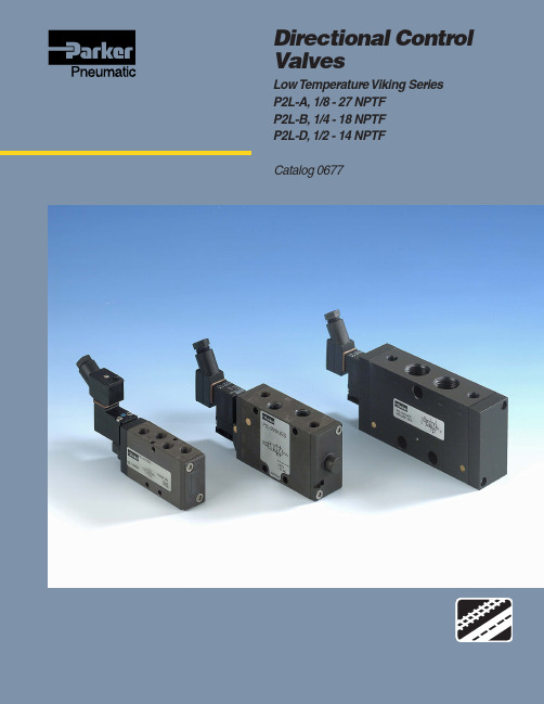
Parker Hannifin Corporation 零温度方向控制阀Viking系列P2L-A、
Directional Control ValvesLow Temperatu re Viking SeriesP2L-A, 1/8 - 27 NPTFP2L-B, 1/4 - 18 NPTFP2L-D, 1/2 - 14 NPTFCatalog 0677!WARNINGFAILURE OR IMPROPER SELECTION OR IMPROPER USE OF THE PRODUCTS AND/OR SYSTEMS DESCRIBED HEREIN OR RELATED ITEMS CAN CAUSE DEATH, PERSONAL INJURY AND PROPERTY DAMAGE.This document and other information from Parker Hannifin Corporation, its subsidiaries and authorized distributors provide product and/or system options for further investigation by users having technical expertise. It is important that you analyze all aspects of your application including consequences of any failure, and review the information concerning the product or system in the current product catalog. Due to the variety of operating conditions and applications for these products or systems, the user, through its own analysis and testing, is solely responsible for making the final selection of the products and systems and assuring that all performance, safety and warning requirements of the application are met.The products described herein, including without limitation, product features, specifications, designs, availability and pricing, are subject to change by Parker Hannifin Corporation and its subsidiaries at any time without notice.Offer of SaleThe items described in this document are hereby offered for sale by Parker Hannifin Corporation, its subsidiaries or its authorized distributors. This offer and its acceptance are governed by the provisions stated on the separate page of this document entitled “Offer of Sale”.© Copyright 2004, Parker Hannifin Corporation. All Rights Reserved.2Directional control valvesVikingSummary Page General information (5)Order key (6)Flow characteristics (7)Technical data............................................................................................7-8 Main data, pneumatically actuated.. (9)Dimensions, pneumatically actuated.......................................................10-11 Main data, electrically actuated, complete valves for 24 V AC/DC. (12)Main Data, electrically actuated (supplied without solenoid valves) (13)Dimensions, electrically actuated............................................................14-15 Main data, hand operated, lever 90° to ports (16)Dimensions, hand operated, lever 90° to ports........................................17-18 Main data, hand operated, lever in line with ports.. (19)Dimensions, hand operated, lever in line with ports (20)Main data, hand operated, manual locking (21)Dimensions, hand operated, manual locking (22)Solenoid valves order key (23)Solenoids 15mm NC, mobile (24)Cable plugs (25)Solenoid dimensions (26)Offer of sale (27)Conversion factors1 kg= 2.2046 lb1 N= 0.22481 lbf1 bar= 14.504 psi1 l= 0.21997 UK gallon1 l= 0.26417 US gallon1 cm3= 0.061024 in31 m= 3.2808 feet1 mm= 0.03937 in9/5 °C + 32 = °F34Directional control valvesVikingThe Viking valve range is robust, versatile and combines high performance with compact installation dimensions. Large flow capacity, short change-over times and low change-over pressure are important characteristics of this valve range.Viking valve rangeP2L-A, dimension 1/8 - 27 NPTF, P2L-B, dimension 1/4 - 18 NPTF, P2L-D, dimension 1/2 - 14 NPTFThe P2L-A, P2L-B and P2L-D have a wide range of hand, foot,pneumatic and electrically operated valves in both 5/2 and 5/3configurations.The Viking range is available in both standard and low temperature versions.5Directional control valvesVikingCompact dimensions, direct body porting and integral mounting holes are all features of the Viking range In addition to simple single installation, the Viking range may be installed in very compact blocks.Rust and corrosion resistant designs.Viking valves are made entirely of anodized aluminium, forcorrosion resistance. The smooth design, with no dirt-collecting pockets, makes the valve suitable for most environments,including applications with stringent hygiene requirements. The valve has stainless steel screws for the end covers, to withstand aggressive environments.Mobile applicationsCommission and service is facilitated by the generously sized,ergonomically designed buttons for manual operation on the P2L-B valve range, which are a standard feature. These make it very easy to see the valve spool position during fault finding.A wide range of solenoid valvesA robust anodized aluminium valve housing, standard and low-temperature versions, hand lever with built-in catch for reliable retention in position, variants designed for a special NO (normally open) mobile solenoid valve, and several varieties of specialmobile (NC) solenoid valves make the valve an excellent choice in mobile applications.High reliabilityManual override - indication on the P2L-BA number of different versions of our solenoid valves P2E with 15 mm DIN 43650 form C enclosures are available to suit justabout any application. The valve has small installation dimensions,low energy consumption, large flow diameter, large flow capacity,a robust valve body, high reliability and long service life. With or without flush locking, extended non locking manual override, with long or short arm, spring biased or indexing.Low noise levelThe exhaust air from the pilot valves is exhausted through a silencer located in the end cover or body, to give the lowest possible noise level. This is particularly important for industries where low noise levels are required. The silencers make it possible for the valves to comply with the EU Machinery Directive,Noise 1.5.8.CertificationThe solenoid valves are protection class IP65 with the standard cable plug. The cable plug with reinforced protection raises the protection standard to IP67.Several types of cable plugsCompact installation dimensions - flexible installationValves easily comply with the requirements for componentreliability in accordance with the EU Machinery Directive standards EN292-2 and EN983.In the P2L-A: few moving parts combined with short spoolmovement give a valve with high reliability and long service life. It is designed for use with, or without supplementary lubrication.In the P2L-B and P2L-D: high molecular weight plastics with self-lubricating properties make it suitable for use with, or without supplementary lubrication.MaintenanceSize A and B spare parts = new valve.With or without suppression, LED and rectifier. For connection to your own cables or with molded cable. A large selection allows you to choose cables to meet your requirements.Insensitive to dirty airThanks to large flow passage areas and the large flow diameter of 1.0 in the pilot valves, the P2L-A, P2L-B and P2L-D can be used in normal industrial or mobile environments without any problems of sticking. However, the service life of the valve depends on thecleanliness of the air. Please refer to ISO 8573.Directional control valves Viking Order key67Flow characteristicsFlow capacities in accordance with ISO6358.All pressures = effective pressureThe curves in the diagram below are typical only.P2L-AP2L-BDirectional control valvesVikingP2L-DTechnical dataP2L-ADimension1/8 - 27 NPTFOperating pressure, max 145 psi (10 bar)* Also see “Operating pressure”.Operating temperature range for directional control valves low temp. version-40 to 86 °F (–40 to +30 °C)Operating temperature range for P2E solenoid valves mobile version -40 to 158 °F (–40 to +70 °C)FlowCv=0.76(Flow acc. to ISO 6358)(C=3,0 Nl/s x bar)(b=0.3)(Qn=12.7 l/s)(Qmax=21.0 l/s)P2L-BDimension1/4 - 18 NPTFOperating pressure, max 145 psi (10 bar)* Also see “Operating pressure”.Operating temperature range for directional control valves low temp. version-40 to 86 °F (–40 to +30 °C)Operating temperature range for P2E solenoid valves mobile version -40 to 158 °F (–40 to +70 °C)FlowCv=1.0(Flow acc. to ISO 6358)(C=4.2 Nl/s x bar)(b=0.2)(Qn=17.0 l/s)(Qmax=29.4 l/s)P2L-DDimension1/2 - 14 NPTFOperating pressure, max 145 psi (10 bar)* Also see “Operating pressure”.Operating temperature range for directional control valves low temp. version-22 to 86 °F (–30 to +30 °C)Operating temperature range for P2E solenoid valves mobile version -40 to 158 °F (–40 to +70 °C)FlowCv=2.9(Flow acc. to ISO 6358)(C=12 Nl/s x bar)(b=0.2)(Qn=48.0 l/s)(Qmax=84.0 l/s)3003x1056006x1059009x105120012x105150015x105180018x105210021x105Flow [l/s][l/min][Sccm]6001200180024003000[l/min]Flow[l/s]6x10512x10518x10524x10530x105[Sccm]1200240036004800600072008400[l/min]Flow[l/s]12x10524x10536x10548x10560x10572x10584x105[Sccm]8Material specificationP2L-A ValveValve body Anodized aluminium End coversAnodized aluminium or Reinforced thermoplasticLever housing Acetal plastic Spool Aluminium + nitrile rubber Piston Acetal plastic/ Anodized aluminium U-rings, O-rings Nitrile rubber End cover sealings Nitrile rubber End cover screws Stainless steel Springs Dacromet® - processed steel,Stainless steelLever Reinforced polyamid plastic Panel mounting nut Polycarbonate plastic Gaiter Chloroprene rubber Mounting screws for solenoid Stainless steelP2L-B ValveValve body Anodized aluminium Spool Acetal plastic/ Anodized aluminiumPistonAcetal plastic /Anodized aluminiumLiningReinforced thermoplastic End covers Anodized aluminium Sliding seals Thermoplastic U-rings, O-rings Nitrile rubber End cover sealings Nitrile rubberPush button for manual changeoverAcetal plastic End cover screws Stainless steel Springs Stainless steel LeverZinc-plated steel Catch for lever Stainless steelKnob Phenolic plastic/Anodized aluminium Gaiter Chloroprene rubber Foot pedalAluminiumMounting screws for solenoidZinc-plated steelDirectional control valvesVikingP2L-D ValveValve body Anodized aluminium Spool Anodized aluminium Piston Brass LiningBrassEnd covers Anodized aluminium Sliding seals Thermoplastic U-rings, O-rings Nitrile rubber End cover sealings Nitrile rubber End cover screws Stainless steel Springs Stainless steel LeverStainless steel Catch for lever Zinc-plated steel Knob Thermoplastic GaiterNitrile rubber Distance ringThermoplasticMounting screws for solenoidZinc-plated steelDimensions* Operating pressureFrom 0 to 145 psi (10 bar) connectable in all portsThis is valid with the following exceptions:Electrically actuated valves•If supply pressure is connected to any other port than port 1 [port 1 also provides supply pressure to solenoid(s)] or if the air supply pressure is lower than minimum signal pres-sure it is necessary to use valves with external air supply to solenoid(s。
PADAUK Technology Co. Ltd PMC232 PMS232系列 12位ADC双核
PMC232/PMS232系列带12位ADC、采用FPPA TM技术双核心8位单片机数据手册第0.03版2017年3月27日Copyright 2017 by PADAUK Technology Co., Ltd., all rights reserved10F-2, No. 1, Sec. 2, Dong-Da Road, Hsin-Chu 300, Taiwan, R.O.C.重要声明应广科技保留权利在任何时候变更或终止产品,建议客户在使用或下单前与应广科技或代理商联系以取得最新、最正确的产品信息。
应广科技不担保本产品适用于保障生命安全或紧急安全的应用,应广科技不为此类应用产品承担任何责任。
关键应用产品包括,但不仅限于,可能涉及的潜在风险的死亡,人身伤害,火灾或严重财产损失。
应广科技不承担任何责任来自于因客户的产品设计所造成的任何损失。
在应广科技所保障的规格范围内,客户应设计和验证他们的产品。
为了尽量减少风险,客户设计产品时,应保留适当的产品工作范围安全保障。
提供本文档的中文简体版是为了便于了解,请勿忽视文中英文的部份,因为其中提供有关产品性能以及产品使用的有用信息,应广科技暨代理商对于文中可能存在的差错不承担任何责任,建议参考本文件英文版。
目录1. 单片机特点 (8)1.1. 系列特点 (8)1.2. 高性能RISC CPU架构 (8)1.3. 系统功能 (8)1.4. 封装信息 (9)2. 系统概述和方框图 (10)3. PMC232系列引脚功能描述 (11)4. PMS232系列引脚功能描述 (12)5. 器件电气特性 (15)5.1. 直流/交流特性 (15)5.2. 最大范围 (17)5.3. ILRC频率与VDD、温度关系的曲线图 (18)5.4. IHRC频率与VDD、温度关系的曲线图 (19)5.5. 工作电流量测值@系统时钟=ILRC÷N (20)5.6. 工作电流量测值@系统时钟=IHRC÷N (20)5.7. 工作电流量测值@系统时钟=4MH Z晶振EOSC÷N (21)5.8. 工作电流量测值@系统时钟=32K H Z晶振EOSC÷N (21)5.9. IO引脚输出驱动电流(I OH)和灌电流(I OL)曲线图 (22)5.10. 测量的IO输入阈值电压(V IH/V IL) (22)5.11. IO引脚拉高阻抗曲线图 (22)5.12. 输出(VDD/2)偏置电压与VDD关系的曲线图 (23)5.13. 开机时序图 (23)6. 功能概述 (24)6.1. 处理单元 (24)6.1.1程序计数器 (25)6.1.2 堆栈指针 (25)6.1.3 一个处理单元工作模式 (26)6.2. OTP程序存储器 (27)6.2.1 程序存储器分配 (27)6.2.2 两个处理单元工作模式下程序存储器分配例子 (27)6.2.3 一个处理单元工作模式下程序存储器分配例子 (28)6.3 程序结构 (29)6.3.1 两个处理单元工作模式下程序结构 (29)6.3.2 一个处理单元工作模式下程序结构 (29)6.4 启动程序 (30)6.5 数据存储器 (31)6.6 算术和逻辑单元 (31)6.7 振荡器和时钟 (32)6.7.1 内部高频振荡器(IHRC)和低频振荡器(ILRC) (32)6.7.2 单片机校准 (32)6.7.3 IHRC频率校准和系统时钟 (32)6.7.4 晶体振荡器 (34)6.7.5 系统时钟和LVR水平 (35)6.7.6 系统时钟切换 (36)6.8 16位定时器(T IMER16) (37)6.9 8位PWM定时器(T IMER2) (39)6.9.1 使用Timer2产生定期波形 (40)6.9.2 使用Timer2产生8位PWM波形 (41)6.9.3 使用Timer2产生6位PWM波形 (43)6.10 看门狗定时器 (44)6.11 中断 (45)6.12 掉电模式 (47)6.12.1 省电模式(stopexe) (47)6.12.2 掉电模式(stopsys) (48)6.12.3 唤醒 (49)6.13 IO端口 (50)6.14 复位和LVR (51)6.14.1 复位 (51)6.14.2 LVR (51)6.15 VDD/2偏置电压 (51)6.16 数字转换(ADC)模块 (52)6.16.1 AD转换的输入要求 (53)6.16.2 ADC分辨率选择 (54)6.16.3 ADC 时钟选择 (54)6.16.4 AD转换 (54)6.16.5 模拟引脚的配置 (54)6.16.6 使用ADC (54)7. IO寄存器 (55)7.1 算术逻辑状态寄存器(FLAG),IO地址=0X00 (55)7.2 FPP单元允许寄存器(FPPEN),IO地址=0X01 (55)7.3 堆栈指针寄存器(SP),IO地址=0X02 (55)7.4 时钟控制寄存器(CLKMD),IO地址=0X03 (56)7.5 中断允许寄存器(INTEN),IO地址=0X04 (56)7.6 中断请求寄存器(INTRQ),IO地址=0X05 (56)7.7 T IMER16控制寄存器(T16M),IO地址=0X06 (57)7.8 通用数据输入/输出寄存器(GDIO),IO地址=0X07 (57)7.9 外部晶体振荡器控制寄存器(EOSCR),IO地址=0X0A (57)7.10 内部高频RC振荡器控制寄存器(IHRCR,只写),IO地址=0X0B (58)7.11 中断边沿选择寄存器(INTEGS,只写),IO地址=0X0C (58)7.12 端口A数字输入禁止寄存器(PADIER,只写),IO地址=0X0D (58)7.13 端口B数字输入禁止寄存器(PBDIER,只写),IO地址=0X0E (59)7.14 端口A数据寄存器(PA),IO地址=0X10 (59)7.15 端口A控制寄存器(PAC),IO地址=0X11 (59)7.16 端口A上拉控制寄存器(PAPH),IO地址=0X12 (59)7.17端口B数据寄存器(PB),IO地址=0X14 (59)7.18端口B控制寄存器(PBC),IO地址=0X15 (59)7.19 端口B上拉控制寄存器(PBPH),IO地址=0X16 (60)7.20 端口C数据寄存器(PC),IO地址=0X17 (60)7.21 端口C控制寄存器(PCC),IO地址=0X18 (60)7.22 端口C上拉控制寄存器(PCPH),IO地址=0X19 (60)7.23 ADC控制寄存器(ADCC),IO地址=0X20 (60)7.24 ADC模式控制寄存器(ADCM,只写),IO地址=0X21 (61)7.25 ADC数据高位寄存器(ADCRH,只读),IO地址=0X22 (61)7.26 ADC数据低位寄存器(ADCRL,只读),IO地址=0X23 (61)7.27 杂项寄存器(MISC),IO地址=0X3B (62)7.28 T IMER2控制寄存器(TM2C),IO地址=0X3C (63)7.29 T IMER2计数寄存器(TM2CT),IO地址=0X3D (63)7.30 T IMER2分频器寄存器(TM2S),IO地址=0X37 (63)7.31 T IMER2上限寄存器(TM2B),IO地址=0X09 (64)8. 指令 (65)8.1 数据传输类指令 (65)8.2 算术运算类指令 (69)8.3 移位运算类指令 (71)8.4 逻辑运算类指令 (72)8.5 位运算类指令 (74)8.6 条件运算类指令 (75)8.7 系统控制类指令 (77)8.8 指令执行周期综述 (79)8.9 指令影响标志的综述 (80)9. 特别注意事项 (81)9.1 警告 (81)9.2 使用IC时 (81)9.2.1 IO使用与设定 (81)9.2.2 中断 (82)9.2.3 切换系统时钟 (82)9.2.4 掉电模式、唤醒以及看门狗 (83)9.2.5 TIMER溢出时间 (84)9.2.6 ADC使用注意事项 (84)9.2.7 LVR (84)9.2.8 IHRC (84)9.2.9 单/双核模式下指令周期差异 (85)9.3 使用ICE时 (85)9.3.1 PMC232/PMS232系列于仿真器PDK3S-I-001/002/003上仿真时 (85)9.3.2 使用PDK3S-I-001/002/003仿真PMC232/PMS232系列功能時注意事項 (86)修订历史:修订日期描述0.01 2015/8/1 初版。
多种电源管理芯片代换

1200AP40 1200AP60、1203P60200D6、203D6 DAP8A 可互代203D6/1203P6 DAP8A2S0680 2S08803S0680 3S08805S0765 DP104、DP7048S0765C DP704加24V的稳压二极管ACT4060 ZA3020LV/MP1410/MP9141ACT4065 ZA3020/MP1580ACT4070 ZA3030/MP1583/MP1591MP1593/MP1430 ACT6311 LT1937ACT6906 LTC3406/AT1366/MP2104AMC2576 LM2576AMC2596 LM2596AMC3100 LTC3406/AT1366/MP2104AMC34063A AMC34063AMC7660 AJC1564AP8012 VIPer12AAP8022 VIPer22ADAP02 可用SG5841 /SG6841代换DAP02ALSZ SG6841DAP02ALSZ SG6841DAP7A、DP8A 203D6、1203P6DH321、DL321 Q100、DM0265RDM0465R DM/CM0565RDM0465R/DM0565R 用cm0565r代换(取掉4脚的稳压二极管)DP104 5S0765DP704 5S0765DP706 5S0765DP804 DP904FAN7601 LAF0001LD7552 可用SG6841代(改4脚电阻)LD7575PS 203D6改1脚100K电阻为24KOB2268CP OB2269CPOB2268CP SG6841改4脚100K电阻为20-47KOCP1451 TL1451/BA9741/SP9741/AP200OCP2150 LTC3406/AT1366/MP2104OCP2160 LTC3407OCP2576 LM2576OCP3601 MB3800OCP5001 TL5001OMC2596 LM2596/AP1501PT1301 RJ9266PT4101 AJC1648/MP3202PT4102 LT1937/AJC1896/AP1522/RJ9271/MP1540SG5841SZ SG6841DZ/SG6841DSM9621 RJ9621/AJC1642SP1937 LT1937/AJC1896/AP1522/RJ9271/MP1540STR-G5643D STR-G5653D、STR-G8653DTEA1507 TEA1533TEA1530 TEA1532对应引脚功能接入THX202H TFC719THX203H TFC718STOP246Y TOP247YVA7910 MAX1674/75 L6920 AJC1610VIPer12A VIPer22A[audio01]ICE2A165(1A/650V.31W);ICE2A265(2A/650V.52W);ICE2B0565(0.5A/650V.23W):ICE2B165(1A/650V.31W);ICE2B265(2A/650V.52W);ICE2A180(1A/800V.29W);ICE2A280(2A/800.50W).KA5H0365R, KA5M0365R, KA5L0365R, KA5M0365RN# u) t! u1 W1 B) R, PKA5L0365RN, KA5H0380R, KA5M0380R, KA5L0380R1、KA5Q1265RF/RT(大小两种体积)、KA5Q0765、FSCQ1265RT、KACQ1265RF、FSCQ0765RT、FSCQ1565Q这是一类的,这些型号的引脚功能全都一样,只是输出功率不一样。
安捷伦示波器探头选型指南1

1.5 m
10:1 500 MHz
1 MΩ, 6-15 pF
400 V CAT II
5000 系列 (500 MHz) 6000 (300 MHz-1 GHz)、 7000、5464x、54830 和 8000 系列
1.5 m
10:1 150 MHz
1 MΩ, 9-17 pF
400 V CAT II
单端有源探头特性
型号 N2795A N2796A 1157A 1158A
衰减 10:1 10:1 10:1 10:1
探头带宽 1 GHz 2 GHz 2.5 GHz 4 GHz
输入动态范围 0 至 ±8 V 0 至 ±8 V 0 至 ±2.5 V 0 至 ±2.5 V
应用和使用 对数字系统和模拟系统设计执行通用、高速探测
10076B N2771B
电缆长度 衰减 典型探头带宽 补偿示波器输入 最大输入电压 推荐示波器
1.5 m
1:1 20 MHz
高阻抗
400 V CAT II
1000、3000、2000 X、3000 X、5000、6000、 7000、8000、54600 系列
1.3 m
1:1 35 MHz
1 MΩ
衰减
要根据测试信号的幅度和示波 器 垂 直 灵 敏 度 范 围, 选 择 探 头 的 衰 减比 (1:1、10:1、100:1、1000:1)。
带宽 (BW)
探头的额定带宽应与示波器相 匹 配, 并 保 有 对 测 试 信 号 的 裕 量。 但 在 较 高 频 率 时, 地 线 电 感 和 输 入 电容对系统性能的影响比探头带宽 的影响更大。
最大输入电压 (Vmax)
为了确保用户安全,同时帮助用 户保护示波器输入不会受到破坏性电 压的影响及避免探头损坏,所选探头 的额定电压必须高于被测信号。
MK7-3型拦阻装置缓冲系统动力学分析
MK7-3型拦阻装置缓冲系统动力学分析MK7-3型拦阻装置是一种用于必要情况下快速制动飞机的航空器设备。
它可以被认为是一种机械缓冲系统,其原理类似于汽车的刹车。
在使用拦阻装置制动时,引擎的推力将被很快地减少,直到飞机全身被压在机载拦阻装置上。
这可以有效地防止飞机跑到跑道的另一端或撞上别的飞机或障碍物。
MK7-3型拦阻装置的缓冲系统包括的主要配件有过渡摆臂、滑车、缓冲桩和冲击装置。
其中,冲击装置可以是液压、气压或机械式的。
液压冲击装置是最常见的一种类型,因为它能够提供最优的动力学表现。
液压冲击装置可以提供多种不同的阻尼和缓冲力度,可以针对不同的需要进行调整。
MK7-3型拦阻装置的缓冲系统动力学分析主要涉及到四个方面的内容:动能、动量、速度和力。
动能是指飞机在着陆时的全部能量。
这个能量可以携带飞机几百吨的重量,因此需要被完全消耗掉。
动能的消耗是由拦阻装置的缓冲系统来完成的,主要靠挡板、阻力板和绷缩装置等来完成刹车过程。
这些部件需要经常维修和更换,以确保它们的性能始终如一。
动量是指飞机在垂直方向上的运动量。
它是通过拦阻装置的过渡摆臂来控制的。
过渡摆臂有两个作用:一方面,它可以将飞机从高速运动转换成减速和停止;另一方面,它可以控制飞机的下降速率,使飞机尽可能平缓地接触地面。
速度是指飞机在水平面上的运动速度。
在拦阻过程中,飞机的速度必须被迅速减少,因此大量的制动力度必须被施加。
这种制动力度是通过滑车和缓冲桩来完成的。
滑车具有很强的摩擦力,可以将飞机快速减速;而缓冲桩则可以在终止移动时吸收大量的能量。
力是指拦截装置对飞机的制动力。
制动力由引擎的减速、滑车的摩擦和缓冲桩的弹性组成。
这些力需要相互合作,以确保能够将飞机都制动和停止于跑道上。
总的来说,MK7-3型拦阻装置的缓冲系统动力学分析是一个复杂的过程,需要考虑到许多不同的因素。
这些因素包括飞机重量、飞机速度、拦截装置的阻力、摩擦力和弹性以及缓冲器的配置等。
爱华AIWA磁带随身听型号鉴

爱华AIWA磁带随身听型号鉴单放:PX,P,PL,PS,GS,GM。
PX是单方的轻触电控机器,最高档的,P一般是机械铁机心,PS一般是最抵挡的塑料机心机器,PL 也非常老,也是电控轻触,但是他面板一般有点透明部分,而px一般看不到带,GS也非常抵挡的单方,GM很少,只是用点金属壳的抵挡机器。
收放:TX,RX,T,RL,TA。
RX是收方的轻触电控机器收音是数字,属高档机器,T是机械铁机器比较老,TX是一般带数字收音机,RL非常老,而且是超博的电控机器,但是收音是机械的,TA是非常抵挡的收方收录放:JX,J,JL,JS,EX(只有个EX50,EX3000都是针对日本的纪念)。
JX是收录放的轻触电控机器收音一般是数字,也少的是机械的,但是都不能看到磁带,J是机械铁机心,JS是J的接班,但是只有厚机器,JL也非常老,收音机械,轻触电控,能看到带子。
1980年推出TP-S30。
是世界首台最轻最小专业立体声录音随身听。
1981年推出HS-P1。
从外形看几乎与TP-S30如出一辙,但是取消了录音功能,耳机的型号也发生了变动。
是首台单放随身听。
是爱华成立30周年纪念机型。
1982年推出HS-M2。
外形非常漂亮。
是1982年时的世界最小最轻随身听,虽然从今天的眼光看它仍然是款“板砖机”,外形非常漂亮。
1983年推出HS-P5。
是一款很顶级的机器, 当时世界上最轻最小的磁带随身听,使用两节7号电池。
具有真实且华丽的强大解析力和浑厚有味妙不可言的音色能够轻易打败同时期的所有SONY WALKMAN。
几乎是那时甚至后来的大部分机型所无法比拟的梦幻机型。
1985年推出HS-R8。
其线控跟耳塞是分开设计的。
是世界上第一款使用线控的随身听。
1986年推出HS-UV9。
是世界第一款具有TV(VHF/UHF)收音功能的随身听。
1986年推出HS-P9。
高频飘逸,音质超绝。
推出HS-F7。
是录音功能媲美SONY的专业WALKMAN WM-D6C的AIWA录放随身听,音质大大超过D6C。
- 1、下载文档前请自行甄别文档内容的完整性,平台不提供额外的编辑、内容补充、找答案等附加服务。
- 2、"仅部分预览"的文档,不可在线预览部分如存在完整性等问题,可反馈申请退款(可完整预览的文档不适用该条件!)。
- 3、如文档侵犯您的权益,请联系客服反馈,我们会尽快为您处理(人工客服工作时间:9:00-18:30)。
2008年8月9日Application Note AP-MK7-0024
产品名称
z MK7XXXXX系列芯片
例案标题
z MK7XXXXX系列芯片MK7A22P 转换成 MK7A23P
使用说明
MK7A22P与 MK7A23P 只有在A/D(AD_CTL3)设定有差异, 如果只使用
一个A/D Channel input, 那么程序不须作修改就可Compatible, 要注意的 是此A/D Channel input 如果不是设在ADC0(PA0), 那么未使用的Analog Input就须设为Output, 才不会耗电(input floating).
例子1 : 只使用一个A/D channel in
A.
MK7A22P
MOVLA 00H
MOVAM AD_CTL1 ; ADC0为Channel in;
MOVLA 01H
MOVAM AD_CTL3 ; ADC0 analog input ;
如果只使用ADC0, 程序不须作修改就可直接当作MK7A23P使用.
B.
MK7A22P :
MOVLA 03H
MOVAM AD_CTL1 ; ADC3为Channel in;
MOVLA 04H
MOVAM AD_CTL3 ; ADC0~ADC3为analog input ;
改成MK7A23P :
MOVLA 03H
MOVAM AD_CTL1 ; ADC3为Channel in;
MOVLA 04H
MOVAM AD_CTL3 ; ADC3为analog input ;
ADC0(PA0), ADC1(PA1), ADC2(PA2) 会变成正常I/O, 所以要设成output BC PA_DIR,0 ;PA0=output ;
BC PA_DIR,1 ;PA1=output ;
第1頁
2008年8月9日Application Note AP-MK7-0024 BC PA_DIR,2 ;PA2=output ;
例子2 : 使用2个以上A/D channel in
MK7A22P
ADC0 :
MOVLA 00H
MOVAM AD_CTL1 ; ADC0为Channel in;
MOVLA 04H
MOVAM AD_CTL3 ; ADC0~ADC3为 analog input ;
:
:
:
:
ADC1
MOVLA 01H
MOVAM AD_CTL1 ; ADC1为Channel in;
:
:
:
:
改成MK7A23P :
ADC0 :
MOVLA 00H
MOVAM AD_CTL1 ; ADC0为Channel in;
MOVLA 01H
MOVAM AD_CTL3 ; ADC0为 analog input ;
:
:
:
ADC1
MOVLA 01H
MOVAM AD_CTL1 ; ADC1为Channel in;
第2頁
2008年8月9日Application Note AP-MK7-0024
MOVLA 02H
MOVAM AD_CTL3 ; ADC1为 analog input ;
:
:
:
第3頁。
