BS 7371-1-2009 金属紧固件涂层.一般要求和选择指南规范
金属件涂装通用技术条件讲解
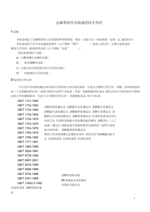
金属零部件涂装通用技术条件1范围本标准规定了金属零部件上的涂装的种类和等级、要求、试验方法、检验规则、包装、运输及贮存。
本标准适用于在不同金属底材零件(以下简称“零件”)表面上进行的、主要以装饰及防腐蚀为目的的一般装饰用涂装(以下简称“涂装”)。
本标准适用如下涂装:a)以酸洗磷化处理的金属;b)真空镀膜的涂装;c)以指向性反射或萤光性为目的的涂装;d)电绝缘性为目的涂装。
2规范性引用文件下列文件中的条款通过本标准的引用而成为本标准的条款。
凡是注日期的引用文件,其随后所有的修改单(不包括勘误的内容)或修订版均不适用于本标准,然而,鼓励根据本标准达成协议的各方研究是否可使用这些文件的最新版本。
凡是不注日期的引用文件,其最新版本适用于本标准。
GB/T 1731-1993GB/T 1732-1993GB/T 1733-1993GB/T 1734-1993GB/T 1735-1979GB/T 1743-1979GB/T 1763-1979GB/T 1764-1979GB/T 1766-1995GB/T 1771-1991GB/T 1865-1989GB/T 2828-1987GB/T 6739-1996GB/T 6807-2001GB/T 9276-1996GB/T 9286-1988GB/T 9754-1988GB/T 9761-1988GB/T 13452.2-1992色漆和清漆漆膜厚度的测定漆膜柔韧性测定法漆膜耐冲击性测定法漆膜耐水性测定法漆膜耐汽油性测定法漆膜耐热性测定法漆膜光泽测定法漆膜耐化学试剂性测定法漆膜厚度测定法色漆和清漆涂层老化评级方法色漆和清漆耐中性盐雾性能的测定漆膜老化(人工加速)测定法逐批检查计数抽样程序及抽样表(适用于连续批次的检查)漆膜硬度铅笔测定法钢铁工件涂装前磷化处理技术条件漆层自然气候曝露试验方法色漆和清漆色漆和清漆色漆和清漆漆膜的划格试验60度镜面光泽的测定色漆的目视比色GB/T 13893-1992色漆和清漆耐湿性的测定3术语下列术语和定义适用于本标准。
钢铁表面处理标准说明及各标准比较
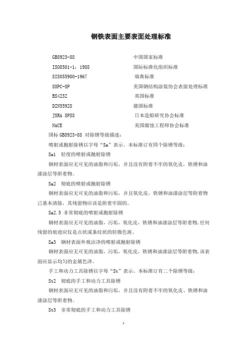
钢铁表面主要表面处理标准GB8923-88 中国国家标准ISO8501-1:1988 国际标准化组织标准SIS055900-1967 瑞典标准SSPC-SP 美国钢结构涂装协会表面处理标准 BS4232 英国标准DIN55928 德国标准JSRA SPSS 日本造船研究协会标准NACE 美国腐蚀工程师协会标准国标GB8923-88 对除锈等级描述:喷射或抛射除锈以字母“Sa”表示。
本标准订有四个除锈等级:Sa1 轻度的喷射或抛射除锈钢材表面应无可见的油脂和污垢,并且没有附着不牢的氧化皮,铁锈和油漆涂层等附着物。
Sa2 彻底的喷射或抛射除锈钢材表面应无可见的油脂和污垢,并且氧化皮,铁锈和油漆涂层等附着物已基本清除,其残留物应该是附着牢固的。
Sa2.5 非常彻底的喷射或抛射除锈钢材表面应无可见的油脂,污垢,氧化皮,铁锈和油漆涂层等附着物,任何残留的痕迹应仅是点状或条纹状的轻微色斑。
Sa3 钢材表面外观洁净的喷射或抛射除锈钢材表面应无可见的油脂,污垢,氧化皮,铁锈和油漆涂层等附着物,该表面应显示均匀的金属色泽。
手工和动力工具除锈以字母“St”表示。
本标准订有二个除锈等级:St2 彻底的手工和动力工具除锈钢材表面应无可见的油脂和污垢,并且没有附着不牢的氧化皮、铁锈和油漆涂层等附着物。
St3 非常彻底的手工和动力工具除锈钢材表面应无可见的油脂和污垢,并且没有附着不牢的氧化皮、铁锈和油漆涂层等附着物。
除锈应比St2更为彻底,底材显露部分的表面应具有金属光泽。
我国的除锈标准与相当的国外除锈标准对照表注:SSPC中的Sp6比Sa2.5 略为严格,Sp2为人工钢丝刷除锈,Sp3为动力除锈。
表面粗糙度及其评定喷砂、抛丸、手工和动力除锈,其目的除达到前述一定的表面清洁度外,还会对钢铁表面造成一定的微观不平整度,即表面粗糙度。
对于涂漆前钢铁表面的粗糙度通常以一些主要的波峰和波谷间的高度值来表示。
钢铁表面粗糙度对漆膜的附着力,防腐蚀性能和保护寿命有很大影响。
msj1-7351标准
msj1-7351标准一、总则本标准规定了本公司生产的相关产品检测的规范和要求,以确保产品质量符合相关法规和标准。
二、适用范围本标准适用于本公司所有生产的产品,包括但不限于电子设备、机械设备、医疗器械等。
三、检测方法与流程1.外观检测:a.对产品外观进行全面检查,包括尺寸、颜色、表面质量等。
b.使用适当的测量工具和设备进行尺寸测量,确保产品符合设计要求。
c.检查表面是否有划痕、凹陷、凸起等明显缺陷。
2.结构检测:a.对产品结构进行检测,确保其符合设计要求,并能够满足产品功能要求。
b.对关键部件进行检查,确保其连接紧密、牢固。
c.检查产品是否有明显的松动或损坏。
3.材料检测:a.对产品所使用的材料进行检测,包括材料种类、质量、成分等。
b.对材料进行化学分析,确保其符合相关标准和质量要求。
c.检查材料是否有明显的损坏或变质。
4.性能检测:a.对产品性能进行测试,包括但不限于电气性能、机械性能、安全性能等。
b.使用适当的测试设备和工具进行性能测试,确保产品符合相关标准和质量要求。
c.对产品的环境适应性进行测试,包括温度、湿度、震动、冲击等。
具体检测流程如下:1.样品接收:供应商将样品送至检测部门,检测部门对样品进行登记和确认。
2.初步检测:对样品进行初步检查,包括外观和结构检测。
3.实验室测试:根据检测方法与标准,对样品进行实验室测试,包括材料和性能测试。
4.结果评估:根据测试结果,对产品进行评估,确定是否符合相关标准和质量要求。
若不符合,则需进行返工或报废处理。
若符合要求,则将报告提交给相关部门负责人进行审批。
5.出具报告:将检测结果以报告形式呈现,提交给上级领导和客户。
同时,对于返工或报废的产品,需及时通知相关部门并做好相应的记录和反馈工作。
6.不合格品处理:对于不合格品,相关部门应立即停止使用,并采取相应措施进行整改和返工,直至合格为止。
同时,应将不合格品的情况上报上级主管部门并采取相应的预防措施,防止类似问题再次发生。
航空钣金维修-紧固件

3.1盲钉的分类
1.Cherry系列,如cherry lock(cr2)、cherry Max(cr3)、cherry maxibolt(cr7) 2.NAS系列,NAS1921XX(凸头)、NAS1919XX 3.BACR15XX系列 4.MS9035XXX系列 (工作中用的最多的主要是cherry系列以及NAS系列,下面主要讲述一下这两个件
2.Rivet(铆钉)
2.1、Rivet(铆钉)
一般对于铆钉材质,可以根据铆钉头上面的标志来判断区分,可以参照下面图
说明一下,DD钉经过了热处理,使用时在低温状态下取出来,在短时 间内尽早使用完
2.1、Rivet(铆钉)
2.1、Rivet(铆钉)
接下来说一下铆钉的件号规律特点,件号主要是规范不同,后面的几乎大同小异没 啥区别。先举几个列子:
航空紧固件
接下来我将逐步介绍一下本人在航空领域所使用频率高的紧固件,包括紧固件安装拆除 以及相应件号规律等,定义性的东西网上有大把就不说了。(以下均是本人靠经验总结, 仅供参考学习)
董汪同学 2020-05-11
一、紧固件的种类(包括但不局限以下)
1. Screw、Bolt、Nut plate 2. Rivet 3.Blind rivets 4.ASP 5.JO-BOLT 6.HI-LOK和HI-LITE 7、其他
③.NAS10976AD8
这种美国通用标准规范的铆钉不多,会在盲钉中常见到,NAS1097和NAS1200代表小 埋,后面的标码位置跟前面的表示的一样。不过需要注意的是对于小埋,它的特性是 shear 即抗剪力,而对于大埋的特性是tension即抗拉。
2.2、铆钉的安装
①、对于件号的选取主要参照手册,不过如果手册中对于长度的选取说以实际为主的话, 这时候就需要用勾尺勾长度来选择件号长度。
紧固件检验规范
紧固件检验规范1.适用范围:适用于外购输电线路铁塔、输电线路附件及通讯塔用紧固件的检验。
2.引用标准:GB/T2694《输电线路铁塔制造技术条件》GB5780《六角头螺栓--C级》GB90《紧固件验收检查、标志与包装》GB/T2828.1《按接收质量限(AQL)检索的逐批检验抽样计划》GB/T41《六角头螺母--C级》GB/T3098.1《紧固件机械性能螺栓、螺钉和螺柱》GB/T3098.2《紧固件机械性能螺母粗牙螺纹》GB/T5779.1《紧固件表面缺陷螺栓、螺钉和螺柱》一般要求GB/T5779.2《紧固件表面缺陷螺母》GB/T90.1《紧固件验收检查》DL/T764.4《输电线路铁塔及电力金具紧固用冷镦热浸镀锌螺栓与螺母》GB95《平垫圈C级》3.职责质量管理部负责本规程的实施。
4.检验模式批量检验一般外购产品是在30000--150000件时,在批量中进行随机抽样检查,抽样样本单位为80件。
结构部分5.抽样项目5.1螺栓抽样项目及检验方法见表55.2螺母抽样项目及检验方法见表65.3脚钉抽样项目及检验方法见表75.4平垫圈抽样项目及检验方法见表86.质量等级产品批量检查应判定质量等级。
6.1螺栓质量等级判定按表1规定执行表1 螺栓质量等级判定表n--样本大小 c--合格判定数6.2螺母质量等级判定按表2规定执行表2 螺母质量等级判定表n--样本大小 c--合格判定数6.3脚钉质量等级判定按表3规定执行表3 脚钉质量等级判定表n--样本大小 c--合格判定数6.4平垫圈质量等级判定按表4规定执行表4平垫圈质量等级判定表n--样本大小 c--合格判定数7.检验程序7.1在批量中随机抽取样本。
7.2外观检查7.3尺寸精度检查7.4机械性能试验7.5质量等级判定8.检查8.1对样本进行逐项检查,并分项记录其缺陷数.若某项缺陷数大于该项的判定数c,则该项抽查不合格;若某项缺陷数小于或等于其判定数c,则该项抽查符合其质量等级。
铝合金阳极氧化膜及有机聚合物膜用JJF(有色金属) 0004─2020_0_split
引言
本规范依据国家计量技术规范 JJF 1071—2010《国家计量校准规范编写规则》、JJF 1001-2011《通用计量术语及定义》和 JJF 1059.1-2012《测量不确定度评定与表示》编制。
本规范是首次制定。
II
JJF(有色金属1 )0004-2020
铝合金阳极氧化膜及有机聚合物膜用喷磨试验仪校准规范
1 范围 本规范适用于新生产、使用中、修理后的铝合金阳极氧化膜及有机聚合物膜用喷磨
试验仪(以下简称喷磨仪)的校准。 2 规范性引用文件
本规范引用了下列文件: JJF 1059.1 测量不确定度评定与表示 GB/T 4957 非磁性基体金属上非导电覆盖层覆盖层厚度测量涡流法 凡注日期的引用文件,仅注日期的版本适用于本规范;凡是不注日期的引用文件, 其最新版本(包括所有的修改单)适用于本规范。 3 术语和计量单位 3.1 供料漏斗 供料漏斗用于储存磨料,能以(20g/min~30g/min)±1g/min的速度供料。 3.2 计量单位 微米(μm),秒(s),毫米(mm),千帕(kPa) 4 概述 喷磨仪包括管路系统、控制系统、测量系统,用于铝合金阳极氧化膜和有机聚合物 膜的耐磨性能试验,包括A型和B型两种。利用稳定的空气压力将磨料冲击到膜层表面, 通过测量将膜层磨破或磨痕尺寸达到规定长度时所用的磨料质量或时间来表征膜层的 耐磨性。图1给出了A型喷磨仪构造示意图,图2给出了B型喷磨仪构造示意图,图3给出 了喷磨仪喷嘴的结构示意图,可以根据设备设计使用合理的结构尺寸。
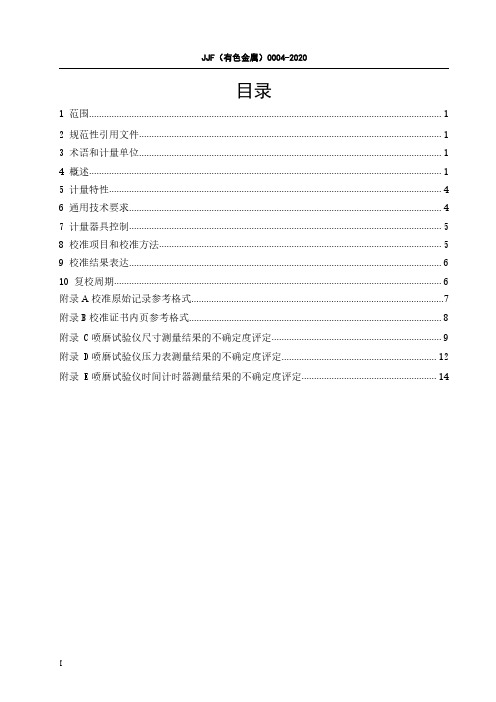
JJF(有色金属I )0004-2020
目录
1 范围............................................................................................................................................. 1 2 规范性引用文件......................................................................................................................... 1 3 术语和计量单位......................................................................................................................... 1 4 概述............................................................................................................................................. 1 5 计量特性..................................................................................................................................... 4 6 通用技术要求............................................................................................................................. 4 7 计量器具控制............................................................................................................................. 5 8 校准项目和校准方法................................................................................................................. 5 9 校准结果表达............................................................................................................................. 6 10 复校周期................................................................................................................................... 6 附录 A 校准原始记录参考格式.....................................................................................................7 附录 B 校准证书内页参考格式..................................................................................................... 8 附录 C 喷磨试验仪尺寸测量结果的不确定度评定.................................................................... 9 附录 D 喷磨试验仪压力表测量结果的不确定度评定.............................................................. 12 附录 E 喷磨试验仪时间计时器测量结果的不确定度评定...................................................... 14
紧固件表面处理标准新技术要求
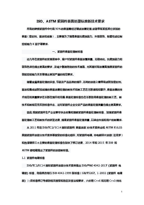
ISO、ASTM紧固件表面处理标准新技术要求所有的碳钢紧固件中约有90%的表面需经过镀或涂履处理,或者带有某些其它添加的表面(密封剂、面涂和润滑),主要是为了提高表面抗腐蚀能力、外观装饰、耐磨性或控制扭矩轴力K因子等要求.一、紧固件表面处理新标准近几年在紧固件的贸易接单中,客户对紧固件表面涂覆质量、无铬钝化、抗腐蚀能力和装饰色泽也提出更高的要求,及减少氢脆危险的技术措施,尤其是对有涂履高强度紧固件的装配扭矩轴力关系等提出更加严谨的规范要求。
随着金属表面处理的环保、节能及产品品质的提升,不同的涂层上需带有或附加密封剂、面涂和集成或附加润滑的表面涂履处理的新技术和新工艺在不断涌现和攀升,表面涂履的技术规范和质量要求在不断在提升和完善,表面处理标准也在不断地将表面处理的新工艺、新技术和新规范充实到标准中去,这对紧固件企业交货产品的表面处理质量也提出更高要求。
因此,我国紧固件生产企业要尽快去收集和理解紧固件表面处理新标准,加强紧固件表面处理新工艺和新技术的研发进度,提高紧固件表面处理质量,以适应市场和用户的新需求.从2011年后ISO/TC2/ SC14国际紧固件(表面涂层)分技术委员会和ASTM F16.03美国紧固件涂层分技术委员等国家的标准化组织,对紧固件电镀、非电解锌片涂层(达克罗)和热浸镀锌三个主要的表面处理标准也加快了修订进度,2014年和2015 年ISO 和ASTM都相继推出了紧固件的涂层新标准。
1.1 紧固件电镀标准ISO/TC2/SC14国际紧固件涂层分技术委员推出ISO/PWI 4042-2017《紧固件电镀层》标准,彻底修改现行ISO 4042-1999版标准(GB/T5267。
1-2002《紧固件电镀层》);该标准修订考虑到相关国家和地区环保法规要求,六价铬Cr+6和无铬Cr+3钝化的技术发展,增添涂层密封剂、面漆和附加润滑新技术条款,以满足涂层紧固件防腐蚀、外观装饰及装配功能要求,及最大限度地减少氢脆危险及相关去氢技术措施。
紧固件检测标准有哪些
紧固件检测标准有哪些
紧固件检测标准通常由国际、国家、行业标准或企业内部标准制定,目的是确保紧固件的质量和性能。
以下是一些可能涉及到紧固件检测的标准:
1.ISO标准:
•ISO 898 - 机械性能的高强度和普通强度六角头螺栓、螺钉和螺柱的技术交付条件。
•ISO 965 - 六角头螺栓和螺钉的一般尺寸。
•ISO 10683 - 镀层螺栓、螺钉和螺柱的防腐性。
•ISO 4014、ISO 4017 - 六角头螺栓的尺寸和技术交付条件。
2.ASTM标准:
•ASTM F606 - 高强度紧固件的机械性能测试。
•ASTM F788 - 镀层螺栓、螺钉和螺柱的防腐性测试。
3.DIN标准:
•DIN 931、DIN 933 - 六角头螺栓的尺寸和技术交付条件。
•DIN EN 20898 - 六角头螺栓的一般尺寸。
4.GB标准(中国国家标准):
•GB/T 5782、GB/T 5783 - 六角头螺栓的尺寸和技术交付条件。
•GB/T 3098.1 - 六角头螺母的类型和尺寸。
5.紧固件检测方法标准:
•根据不同类型的紧固件,可能还有一些特定的检测方法标准,如拉伸测试、硬度测试、扭矩测试等。
请注意,具体的检测标准会因紧固件类型(如螺栓、螺母、螺钉等)、用途和国家/地区而有所不同。
在实际应用中,建议参考所在地区的相关标准或者具体项目的技术规范。
钢铁产品表面涂装及检测的技术标准(精选五篇)
钢铁产品表面涂装及检测的技术标准(精选五篇)第一篇:钢铁产品表面涂装及检测的技术标准钢铁产品表面涂装及检测的技术标准本标准主要适用于钢铁产品表面涂装。
凡合同文件无非凡要求,其产品表面涂装均应符合本标准规定。
一、涂装前表面处理:所有用于设备制造钢铁原材料,涂漆前均需进行表面除锈处理。
并规定时间范围内涂保养底漆(车间底漆)。
1、喷射除锈前,厚锈层应铲除。
并清除油脂污垢。
喷射或除锈后,钢材表面必须清除浮灰碎屑。
2、对于喷射除锈钢材表面规定两个除锈等级。
其文字叙述如下:Sa2彻底喷射除锈:钢材表面无可见油脂污垢,并且氧化皮、铁锈油漆涂层等附着物已基本清除,其残留物应牢固附着。
Sa21/2非常彻底喷射除锈。
钢材表面无可见油脂、污垢,氧化铁油漆层等附着物,任何残留痕迹应仅点状或条纹状稍微色斑。
(网上钢材集散地 )3、对于手工动力工具除锈钢材表面,规定有一个除锈等级,其文字叙述如下:St3非常彻底手工动力工具除锈。
钢材表面无可见油脂污垢,并且没有附着不牢氧化皮、铁锈油漆涂层附着物。
除锈后底材显露部分表面应具有金属光泽。
4、“附着物”这个术语可包括焊渣、焊接飞溅物,可溶性盐类等。
当氧化皮、铁锈或油漆层能以金属腻子刮刀从钢材表面剥离时,均应看成附着不牢。
5、待检查钢材表面应与相应照片进行目视比较。
照片应靠近钢材表面。
评定应良好散射日光下或照度相当人工照明条件下进行。
6、预处理时漆膜厚度及涂料选择如下:a)漆膜(干膜)厚度:15~25μm。
b)涂料品种:无机硅酸锌(车间)底漆、环氧底漆、环氧富锌底漆、磷酸锌底漆、铁红环氧脂底漆等。
c)所用底漆必须产品配套漆系品种或与配套漆系底漆相适应漆种。
二、技术要求:1、涂装前,必须达到规定除锈等级标准后,才答应涂装。
2、轻度腐蚀环境,预备涂刷常规涂料时,其表面除锈等级标准为Sa2级。
3、受化工大气腐蚀、海水侵蚀、高温氧化以及无机富锌涂料为底漆时,表面除锈等级标准为Sa21/2级。
紧固件(螺栓、螺钉、螺柱和螺母)检验规范

标准修订记录表QJ紧固件(螺栓、螺钉、螺柱和螺母)检验规范XXXXXXXXXXXXXXX有限公司发布精选文档,欢迎下载目次前言 ............................................................................................................................................................... I I1 范围 (1)2 规范性引用文件 (1)3 技术要求及试验方法 (1)4 检验规则 (3)5 标志、包装、运输和贮存 (4)附录 A (规范性附录)检验报告模板 (5)附录 B (规范性附录)头部坚固性试验 (6)精选文档,欢迎下载前言发布的标准,作为公司内部使用的技术法规性文件。
本精选文档,欢迎下载紧固件(螺栓、螺钉、螺柱和螺母)检验规范1 范围本标准规定了螺栓、螺钉、螺柱和螺母的技术要求及试验方法,标志、包装、运输和贮存。
本标准适用于公司产品用螺栓、螺钉、螺柱和螺母的检验。
2 规范性引用文件下列文件对于本文件的引用是必不可少的,凡是注日期的引用文件,仅注日期的版本适用于本文件。
凡是不注日期的引用文件,其最新版本(包括所有的修改单)适用于本文件。
GB/T 90.2 紧固件标志与包装GB/T 3098.1 紧固件机械性能螺栓、螺钉和螺柱GB/T 3098.2 紧固件机械性能螺母粗牙螺纹GB/T 3098.3 紧固件机械性能紧定螺钉GB/T 3098.4 紧固件机械性能螺母细牙螺母GB/T 3098.6 紧固件机械性能不锈钢螺栓、螺钉、螺柱和螺母GB/T 3098.15 紧固件机械性能不锈钢螺母GB/T 3098.16 紧固件机械性能不锈钢紧定螺钉GB/T 4334 金属和合金的腐蚀不锈钢晶间腐蚀试验方法GB/T 6478 冷镦和挤压用钢GB/T 17880.6 铆螺母技术条件Q 04 环保标识使用管理规定(试行)Q 1.001 静电粉末喷涂涂膜质量检验要求Q 1.011 外协外购件入厂验收通则Q 99.003 金属零部件涂(镀)层表面质量的检验规范Q 001 环保产品中有害物质控制管理规定3 技术要求及试验方法3.1 外观3.1.1 技术要求产品应消除污垢及金属屑,不应有任何部位上的淬火裂缝、凹痕、皱纹和损伤,表面不应有锈斑,表面镀层应光滑、色泽均匀,锐边倒钝。
紧固件企业标准
紧固件企业标准紧固件企业标准1.范围:本标准规定本公司所有外购紧固件产品/设计/制造与检验标准.2.引⽤标准:GB192 普通螺纹基本⽛型GB193 普通螺纹公称直径与螺距系列GB9144 商品紧固件的普通螺纹选⽤系列GB196 粗⽛普通螺纹和商品紧固件选⽤的细⽛普通螺纹的基本尺⼨ GB9145、9146 商品紧固件常⽤精度普通螺纹的极限尺⼨GB3-79 普通螺纹的螺纹收尾、肩距、退⼑槽和倒⾓GB3103.1、3103.3 紧固件公差GB5779.1 螺栓、螺钉和螺柱表⾯缺陷的⼀般要求GB5779.2 螺母表⾯缺陷的⼀般要求GB5779.3 螺栓、螺钉和螺柱表⾯缺陷的特殊要求GB5267 螺纹紧固件电镀层GB1237 紧固件的标记⽅法GB90 紧固件验收检验、标志与包装GB5276 螺栓、螺钉、螺母的尺⼨代号与标注内容GB2 螺栓、螺柱和机器螺钉的末端型式与尺⼨GB3104 六⾓产品的对边宽度GB3106 普通螺栓的螺纹长度GB3098.1 碳钢与合⾦钢螺栓、螺钉和螺柱的机械性能GB3098.6 不锈钢螺栓、螺钉、螺柱和螺母的机械性能GB5781 六⾓头螺栓-全螺纹-C级GB944.1 螺钉⽤⼗字槽GB3098.3 碳钢与合⾦钢紧定螺钉的机械性能GB818 ⼗字槽盘头螺钉GB70 内六⾓园柱头螺钉GB79 内六⾓圆柱端紧定螺钉GB3098.2 碳钢与合⾦钢螺母的机械性能GB41 1型六⾓螺母-C级GB62 蝶形螺母GB809 嵌装园螺母GB6172 六⾓薄螺母-A和B级-倒⾓GB5280 ⾃攻螺钉⽤螺纹GB3098.5 ⾃攻螺钉的机械性能GB3098.7 ⾃攻锁紧螺钉-粗⽛普通螺纹系列的机械性能GB845 ⼗字槽盘头⾃攻螺钉GB/T13806.2 精密机械⽤⼗字槽⾃攻螺钉-刮削端GB6560 ⼗字槽盘头⾃攻锁紧螺钉-全螺纹GB94.1 弹簧垫圈技术条件GB94.2 齿形、锯形锁紧垫圈技术条件GB95 平垫圈-C级GB96 ⼤垫圈-A和C级GB93 标准型弹簧垫圈GB862.1 外齿锁紧垫圈GB116 铆钉技术条件GB12619 抽芯铆钉技术条件GB/T15855.3 击芯铆钉技术条件GB109 平头铆钉GB873 扁园头半空⼼铆钉GB1013 平锥头半空⼼铆钉GB12618 开⼝型扁圆头抽芯铆钉GB/T15855.1 扁圆头击芯铆钉⾮标准件螺栓、螺钉、⾃攻螺钉、螺母、平垫圈、弹簧垫圈、外齿垫圈、铆钉等可引⽤相关的标准.3.普通螺纹直径和系列要求:(1).普通螺纹公称直径与螺距系列,引⽤ GB193标准.(2).商品紧固件的普通螺纹选⽤系列引⽤ GB9144标准.4.螺栓、螺钉、⾃攻螺钉、螺母、垫圈、铆钉的基本尺⼨:(1). 六⾓头螺栓-全螺纹-C级的基本尺⼨引⽤ GB5781(2). ⼗字槽盘头螺钉的基本尺⼨引⽤ GB818(3). 内六⾓园柱头螺钉的基本尺⼨引⽤GB70(4). 1型六⾓螺母-C级的基本尺⼨引⽤GB41(5). 蝶形螺母的基本尺⼨引⽤GB62(6). 嵌装园螺母的基本尺⼨引⽤GB809(7). 六⾓薄螺母-A和B级-倒⾓的基本尺⼨引⽤ GB6172(8). ⼗字槽盘头⾃攻螺钉的基本尺⼨引⽤GB845(9). 精密机械⽤⼗字槽⾃攻螺钉-刮削端1.材质的基本尺⼨引⽤GB/T13806.2(10). ⼗字槽盘头⾃攻锁紧螺钉-全螺纹的基本尺⼨引⽤ GB6560(11).内六⾓圆柱端紧定螺钉GB79(12). 平垫圈-C级的基本尺⼨引⽤ GB95(13). ⼤垫圈-C级的基本尺⼨引⽤ GB96(14). 标准型弹簧垫圈的基本尺⼨引⽤ GB93(15). 外齿锁紧垫圈的基本尺⼨引⽤ GB862.1(16). 平头铆钉的基本尺⼨引⽤ GB109(17). 扁园头半空⼼铆钉的基本尺⼨引⽤ GB873(18). 平锥头半空⼼铆钉的基本尺⼨引⽤ GB1013(19). 开⼝型扁圆头抽芯铆钉的基本尺⼨引⽤ GB12618(20). 扁圆头击芯铆钉的基本尺⼨引⽤ GB/T15855.15.螺栓、螺钉、⾃攻螺钉、螺母、垫圈、铆钉等的检验要求:(1). 普通螺纹基本⽛型引⽤ GB192(2). 粗⽛普通螺纹的基本尺⼨引⽤ GB196(3). 粗⽛普通螺纹和商品紧固件选⽤的细⽛普通螺纹的基本尺⼨引⽤GB196(4). 商品紧固件常⽤精度普通螺纹的极限尺⼨引⽤ GB9145、9146(5). 普通螺纹的螺纹收尾、肩距、退⼑槽和倒⾓引⽤ GB3(6). 紧固件公差引⽤ GB3103.1、3103.3(7). 紧固件的标记⽅法引⽤ GB1237(8). 螺栓、螺钉、螺母的尺⼨代号与标注内容引⽤ GB5276(9). 螺栓、螺柱和机器螺钉的末端型式与尺⼨引⽤ GB2(10). 六⾓产品的对边宽度引⽤ GB3104(11). 普通螺栓的螺纹长度引⽤ GB3106(12).粗、细⽛碳钢和合⾦钢螺栓、螺钉的最⼩拉⼒载荷和保证载荷引⽤GB3098.1(13).铜螺钉的最⼩拉⼒载荷或铜螺母的保证载荷引⽤GB/T3098.10(14)碳钢和合⾦钢螺母的公称和实际保证应⼒引⽤GB3098.2(15)⼗字槽盘头⾃攻螺钉GB845C型和⼗字槽盘头⾃攻螺钉刮削端- GB/T13806.2 A型的扭矩等机械性能均引⽤GB3098.5; ⼗字槽盘头⾃攻锁紧螺钉GB6560B级的拧⼊⼒矩、拉⼒载荷等其它机械性能引⽤GB3098.7(16)弹簧垫圈的弹性试验等引⽤GB94.1(17) 齿形、锯齿锁紧垫圈弹性试验等引⽤GB94.2(18)抽芯铆钉的抗剪和抗拉最⼩载荷引⽤GB12619(19)击芯铆钉的抗剪和抗拉最⼩载荷等引⽤GB/T15855.3(20)其它未规定铆钉的机械性能,由供需双⽅协议,可对铆钉进⾏可铆性及剪切强度试验.6.螺栓、螺钉、⾃攻螺钉、螺母表⾯镀层和表⾯质量的技术要求:(1). 螺纹紧固件电镀层引⽤ GB5267(2). 螺栓、螺钉和螺柱表⾯缺陷的⼀般要求引⽤ GB5779.1(3). 螺母表⾯缺陷的⼀般要求引⽤ GB5779.2(4). 螺栓、螺钉和螺柱表⾯缺陷的特殊要求引⽤ GB5779.37.螺栓、螺钉、⾃攻螺钉、螺母、垫圈、铆钉的机械性能和技术要求:(1)碳钢螺栓的机械性能为:4.8,表⾯镀锌;不锈钢螺栓的机械性能为:A2-70,(D≤20)(2)碳钢螺钉的机械性能为:4.8,表⾯镀锌;不锈钢螺钉的机械性能为:A2-70不经处理(3)⼗字槽盘头⾃攻螺钉GB845选C型;⼗字槽盘头⾃攻螺钉-刮削端GB/T13806.2选A型;⼗字槽盘头⾃攻锁紧螺钉GB6560选B级,上述各规格的材料均为15号渗碳钢.螺钉的表⾯硬度HRC]45. 表⾯镀锌.或特殊说明.(4)铜螺钉、螺母和平垫圈的机械性能为:CU2,材料为:H63.(5)碳钢螺母的机械性能为:5,表⾯镀锌;不锈钢螺母的机械性能为:A2-70不经处理;碳钢薄螺母的机械性能为:04,表⾯镀锌;不锈钢薄螺母的机械性能为:A2-70不经处理;碳钢蝶形螺母的材料为:Q215表⾯镀锌;嵌装园螺母材料1Cr18Ni9Ti.(6)碳钢平垫圈的机械性能为100HV,表⾯镀锌;不锈钢平垫圈的机械性能为:A140不经处理.(7)碳钢弹簧垫圈的材料为:65Mn,HRC42~50;不锈钢弹簧垫圈的材料为:1Cr18Ni9Ti(8)齿形、锯齿锁紧垫圈材料为:65Mn,HRC40~50,表⾯镀锌.(9)抽芯铆钉的机械性能为:10,钉体材料LF2,钉芯材料15;不锈钢抽芯铆钉的机械性能为:51, ,钉体材料1Cr18Ni9,钉芯材料1Cr18Ni9.型式均为:开⼝型.(10)扁园头击芯铆钉, ,钉体材料为:LF5-1, 钉芯材料为:2Cr13.(11) 扁园头半空⼼铆钉、平锥头半空⼼铆钉的材料均为:铝合⾦,不经处理.(12)螺栓/螺钉/⾃攻螺钉/螺母/垫圈/铆钉等未规定时均为C级.如有特殊要求可在BOM中或图纸上予以说明,⽽且须写上国标代码GB----.8.⾮标准紧固件:对于特殊材料和镀层的螺栓、螺钉、⾃攻螺钉、螺母、垫圈、铆钉等,除可按图要求定制检验外,还可引⽤相关国家标准和本企业标准的第4、5、6、7、9条进⾏定制和检验。
涂层机械性能检测相关国家标准
(GB/T 13891-2008)
《镜面光泽试验方法》(ASTM D523—08)
21
耐沾污性
《建筑涂料涂层耐沾污性试验方法》(GB/T 9780-2013)
22
漆膜颜色
《涂膜颜色的测量方法第一部分:原理》(GB/T 11186.1—1989)、《涂膜颜色的测量方法第二部分:颜色测量》(GB/T 11186.2—1989)、《涂膜颜色的测量方法第三部分:色差计算》(GB/T 11186。3—1989)
37
绝缘漆吸水率
《绝缘漆漆膜吸水率测定法》(HG/T 3856-2006)
38
涂层耐冻融循环性
《建筑涂料涂层耐冻融循环性测定法》(JG/T 25—1999)
39
耐溶剂擦拭性
《用溶剂擦拭法测定硅酸乙酯(无机)富锌底漆的耐MEK擦拭性》(ASTM D4752-10(2015))
《采用溶剂擦拭法测定有机涂料耐溶剂擦拭性》
49
耐干擦性
JC/T 423—91中5.12
50
透水性
GB/T 9779-2005中5。9
51
不粘胎干燥时间
GA/T 298-2001中6.1.5
52
玻璃珠撒布试验
GA/T 298-2001中6。1。13
53
玻璃珠牢固附着率
GA/T 298—2001中6.1。14
54
动态抗开裂性
JG/T 157-2004中附录B
79
覆盖裂缝能力
《表面被覆材抗裂拉伸性试验方法》(JSCE-K532-2007)
80
抗压强度
GB 14907—2002中6.4.7
GB/T 22374-2008中6。4。7
jis f7371标准
jisf7371标准JISF7371标准是日本工业标准中对紧固件的一种规定,该标准详细说明了紧固件的尺寸、性能、材料等方面的要求。
该标准在日本的工业领域得到了广泛的应用,成为了紧固件生产、设计、使用等方面的重要参考依据。
一、标准的适用范围JISF7371标准适用于日本工业领域中使用的各种紧固件,包括螺栓、螺钉、螺母、铆钉、销钉等。
该标准规定了这些紧固件的尺寸、性能、材料、表面处理等方面的要求,适用于各种机械、建筑、车辆、船舶、电子等领域的紧固需求。
二、标准的内容JISF7371标准包括了以下几部分内容:1.紧固件的基本要求:包括紧固件的尺寸、形状、表面处理等方面的规定,以确保其在应用中的安全性和稳定性。
2.紧固件的强度要求:根据不同的使用环境和使用要求,规定了紧固件的抗拉强度和屈服强度等指标,以确保紧固件在使用中能够满足强度要求。
3.紧固件的材质要求:规定了紧固件所使用的材料种类和性能要求,以确保紧固件的质量和可靠性。
4.紧固件的生产和检验要求:规定了紧固件的制造过程和检验方法,以确保生产出的紧固件符合标准要求。
5.紧固件的标记和标识要求:规定了不同种类和规格的紧固件应该如何标记和标识,以便于识别和使用。
三、标准的实施和监督JISF7371标准的实施和监督由日本工业标准化组织负责。
该组织负责对紧固件的生产、设计、使用等方面进行监督和指导,确保紧固件的质量和性能符合标准要求。
同时,该组织还会定期对紧固件的生产企业和使用单位进行抽查和检验,以确保标准的执行效果。
四、标准的意义和影响JISF7371标准的制定和实施,对于日本工业领域中的紧固件生产和应用具有重要的意义和影响。
该标准规范了紧固件的生产和使用,提高了紧固件的质量和性能,保证了工业产品的安全性和稳定性,促进了日本工业的发展和进步。
同时,该标准也成为了其他国家紧固件生产和应用的重要参考依据,对于推动全球紧固件产业的标准化和规范化具有积极的作用。
涂镀国际及国外先进标准
涂镀国际及国外先进标准1.国际标准:ISO 1459-73金属覆盖层热镀锌防腐蚀层指导原则ISO 4999-78工业用连续热镀铅锡(铅合金)冷轧碳钢薄板及其深冲性ISO 5000-80工业用连续热镀铝硅层的冷轧碳钢薄板及其深冲性标准号:ISO 16163-2000... 中文标题:连续热浸镀钢薄板产品.尺寸和形状公差...标准号:ISO 3575-1996... 中文标题:工业联锁成型和拉伸性的连续热浸镀锌碳素薄钢板...标准号:ISO 1460-1992... 中文标题:金属镀层.铁类材料的热浸镀锌涂层.用重量测定法测定单位面积重量...标准号:ISO 1461-1999... 中文标题:加工的钢铁制品的热镀锌层.规范和试验方法...标准号:ISO 4998-1996... 中文标题:连续热镀锌碳钢结构件薄钢板...标准号:ISO 14788-1998... 中文标题:连续热浸5%锌铝合金涂覆钢薄板和卷材...2.日本:JIS G 3314-77(90)热浸镀铝钢板和钢带JIS H 8641-82(88)热浸镀锌JIS H 8642-72(88)热浸镀铝JIS H 8672-72(88)热浸镀铝的试验方法JIS H 9124-87热浸镀锌操作规程JIS H 9126-68 (88)热浸镀铝操作规程. 标准号:JIS H8641-1999... 中文标题:热浸镀锌...标准号:JIS H9124-1999... 中文标题:热浸镀锌的推荐规程...标准号:JIS H0401-1999... 中文标题:热浸镀锌涂覆的试验方法...标准号:JIS G3318-1994... 中文标题:涂漆热浸镀锌5%铝合金镀层钢板和钢带...标准号:JIS G3317-1994... 中文标题:热浸镀锌5%铝合金镀层钢板和钢带...标准号:JIS G3548-1994... 中文标题:镀锌钢丝绳...标准号:JIS G3302-1998... 中文标题:镀锌薄钢板...3.德国:DIN 1616-84镀锡钢板和极薄钢板;种类、尺寸和允许偏差DIN 2444-84钢管镀锌层安装用管热镀锌质量标准DIN 17162T2-80钢质扁制品热镀锌带材与板材交货技术条件普通结构钢DIN 20578-63运输矿车的锌镀层车厢的热镀锌DIN 50976-80防腐;零件的热镀锌涂层要求和检验DIN 50979-89防腐零件的热镀锌要求和检验DIN 59232-78扁钢制品软性非合金钢制和一般结构钢制热镀锌的宽带材料与板材,尺寸、允许尺寸和形状偏差标准号:DIN EN 10147-2000... 中文标题:连续热浸镀锌结构钢带材和薄板.交货技术条件...标准号:DIN EN 10142-2000... 中文标题:冷加工用连续热浸镀锌低碳钢带材和薄板.交货技术条件...标准号:DIN EN 50189-2000... 中文标题:架空导线.镀锌钢丝...标准号:DIN EN 10143-1993... 中文标题:连续热镀钢板和钢带.极根尺寸和形状公差...标准号:DIN EN 10284-2000... 中文标题:聚乙烯(PE)管系统用带压缩端的可锻铸铁配件...标准号:DIN EN 10215-1995... 中文标题:连续热浸镀调质带铝锌覆层的钢带和薄板.交货技术条件...标准号:DIN EN 746-4-2000... 中文标题:工业热加工设备.第4部分:热浸电镀热加工设备的特殊安全要求...标准号:DIN EN 10292-2000... 中文标题:冷加工用高屈服强度的连续热浸镀层钢带材和薄板.交货技术条件...标准号:DIN 50978-1985... 中文标题:金属镀层的检验.热镀锌产生的涂层附着性能...标准号:DIN VDE 0212-54-1986... 中文标题:架空线和配电装置用配件.热镀锌...标准号:DIN 50930-3-1993... 中文标题:金属的腐蚀.由于管槽和装置内的水造成的内部金属腐蚀.热镀锌铁材料腐蚀可能性判定...标准号:DIN V 11535-2-1994... 中文标题:暖房.钢和铝结构1280米宽纵向网格尺寸3065米长...标准号:DIN 267-10-1988... 中文标题:紧固件.交货技术条件.热镀锌零件...标准号:DIN EN ISO 1460-1995... 中文标题:金属镀层.铁类材料的热浸镀锌涂层.用重量测定法测定单位面积重量...标准号:DIN EN 10214-1995... 中文标题:连续热浸镀调质带锌铝覆层的钢带和薄板.交货技术条件...标准号:DIN EN 10154-1996... 中文标题:连续热浸镀调质铝硅涂层(AS)钢带和薄板.交货技术条件...标准号:DIN EN 10240-1998... 中文标题:钢管用内部和/或外部防护涂层.通过在自动设备中热浸镀锡进行的涂层的规定...标准号:DIN EN 10152-1993... 中文标题:电解镀锌冷轧扁钢制品.交货技术条件...标准号:DIN EN 1123-2-1999... 中文标题:排水管道用带插接套的长焊缝焊接热镀锌钢管制管道和管件.第2部分:尺寸...标准号:DIN EN 1123-1-1999... 中文标题:排水管道用带插接套的长焊缝焊接热镀锌钢管制管道和管件...标准号:DIN EN ISO 1461 Bb.1-1999... 中文标题:通过钢上热镀锌产生的锌镀层(块镀锌).要求和检验...标准号:DIN EN ISO 1461-1999... 中文标题:通过钢上热镀锌产生的锌镀层(块镀锌).要求和检验...4.原苏联:TOCT 9.307-89 EC3KC 热锌镀层符号、技术要求验收规则与检验方法5.英国:BS 443-82(90)钢丝镀锌层检验及其质量要求BS 129-71(86)钢铁件热浸镀锌层1. 标准号:BS 2858-1957... 中文标题:制造镀锌罐用钢板规范...2. 标准号:BS 7371-6-1998... 中文标题:金属紧固件涂层.热浸镀锌涂层的规范...3. 标准号:BS 6497-1984... 中文标题:施加并焙固于热浸镀锌的热轧型钢和预成型钢(窗及其外部建筑用)的粉末有机涂层和带有粉末有机涂层的镀锌型钢和预成型钢的精饰规范...4. 标准号:BS EN 1123-1-1999... 中文标题:污水系统用带套管的纵向焊接热浸镀锌钢管及配件.要求、试验和质量控制...5. 标准号:BS EN 10240-1998... 中文标题:钢管内或外保护覆层.用于自动车间的热浸电动覆膜规范...6. 标准号:BS EN 61284-1998... 中文标题:架空线.装配要求和试验...7. 标准号:BS EN ISO 1460-1995... 中文标题:金属镀层.铁类材料的热浸镀锌涂层.用重量测定法测定单位面积重量...8. 标准号:BS EN ISO 1461-1999... 中文标题:加工钢铁制品的热镀锌层.规格和试验方法...9. 标准号:BS ISO 965-5-1999... 中文标题:ISO普通米制螺纹. 公差.第5部分:与镀锌前最大公差位置为H的热浸镀锌外螺纹相匹配的内螺纹的尺寸极限值...10. 标准号:BS ISO 965-4-1999... 中文标题:ISO普通米制螺纹.公差.第4部分:与由镀锌后公差位置为H或G攻出的内螺纹相匹配的热浸镀锌外螺纹的尺寸极限值...11. 标准号:BS EN 746-4-2000... 中文标题:工业热处理设备.热浸电镀热处理设备的特殊安全要求...12. 标准号:BS EN 10147-2000... 中文标题:连续热浸镀锌结构薄钢板和带材.交货技术条件...13. 标准号:BS 3083-1988... 中文标题:普通热浸涂锌和热浸涂铝锌波纹钢板规范...14. 标准号:BS EN ISO 12944-6-1998... 中文标题:涂料和清漆.防护涂层系统对钢结构的腐蚀防护.实验室性能试验方法...15. 标准号:BS EN ISO 14713-1999... 中文标题:铁和钢结构的防腐.锌和铝涂层.指南...6.美国:NF A 46-320-55钢铁产品。
BS 7371-12-2008 金属紧固件涂层.英制紧固件的要求
BS 7371-12:2008 BRITISH STANDARDCoatings on metal fasteners –Part 12: Requirements for imperial fastenersICS 25.220.40; 21.060.10NO COPYING WITHOUT BSI PERMISSION EXCEPT AS PERMITTED BY COPYRIGHT LAWBS 7371-12:2008Publishing and copyright informationThe BSI copyright notice displayed in this document indicates when thedocument was last issued.© BSI 2008ISBN 978 0 580 60930 5The following BSI references relate to the work on this standard:Committee reference FME/9/1Draft for comment 08/30173610 DCPublication historyFirst published July 2008Amendments issued since publicationAmd. no.Date Text affectedBS 7371-12:2008ContentsForeword ii1Scope 12Normative references 13Terms and definitions 14Screw thread dimensions 15Coating thickness 26Application and type of coating 27Measurement of coating thickness 2AnnexesAnnex A (informative) Strip and weigh method for the determination of group and sample average plating thickness of silver 8 Bibliography 9List of tablesTable 1 – Plating thickness 2Table 2 – Screws and bolts: B.S.W. and B.S.F. threads 3Table 3 – Screws and bolts: UNC and UNF threads 4Table 4 – Screws and bolts: B.A. threads 5Table 5 – Screws and bolts: B.S.C. and B.S.P. threads 5Table 6 – Nuts: B.S.W. and B.S.F. threads 6Table 7 – Nuts: B.A. threads 6Table 8 – Nuts: UNC and UNF threads 7Summary of pagesThis document comprises a front cover, an inside front cover, pages i and ii, pages 1 to 9 and a back cover.© BSI 2008•iBS 7371-12:2008ii•© BSI 2008ForewordPublishing informationThis British Standard is published by BSI and came into effecton 31 July 2008. It was prepared by Technical Committee FME/9/1, Coatings on threaded components and accessories. A list of organizations represented on this committee can be obtained on request to its secretary.Information about this documentThis standard supersedes all parts of BS 3382, which are withdrawn. Presentational conventionsThe provisions of this standard are presented in roman (i.e. upright) type. Its requirements are expressed in sentences in which the principal auxiliary verb is “shall”.Commentary, explanation and general informative material is presented in smaller italic type, and does not constitute a normative element.Contractual and legal considerationsThis publication does not purport to include all the necessary provisions of a contract. Users are responsible for its correct application. Compliance with a British Standard cannot confer immunity from legal obligations.BS 7371-12:2008 1ScopeThis standard gives thickness requirements for coatings on imperialmetal fasteners and can be used in conjunction with all parts ofBS 7371.NOTE 1 For information on coating materials, see the relevant part of BS 7371.This standard does not cover components such as self-tapping screws and wood screws.This standard includes area tables (in square inch units) for imperial fasteners, and factors for thickness determination (see Table 2 toTable 8).NOTE 2 Details concerning cadmium have not been included in thisstandard due to the restrictions placed on the marketing and use ofcadmium and its compounds contained in national and internationalregulations.2Normative referencesThe following referenced documents are indispensable for theapplication of this document. For dated references, only the editioncited applies. For undated references, the latest edition of thereferenced document (including any amendments) applies.BS 919-1:2007, Screw gauge limits and tolerances –Part 1: Specification for gauges for screw threads of unified form BS 7371-1, Coatings on metal fasteners – Specification for general requirements and selection guidelinesBS 7371-3, Coatings on metal fasteners – Part 3: Specification for electroplated zinc coatingsBS 7371-4, Coatings on metal fasteners – Part 4: Specification for electroplated nickel, nickel/chromium and copper/nickel/chromium coatings3Terms and definitionsFor the purposes of this British Standard, the terms and definitionsgiven in BS 7371-1 apply.4Screw thread dimensionsThread dimensions of components supplied for plating and after plating shall conform to the relevant screw thread standards.NOTE See BS 919-1:2007, Annex D for the gauging procedure to be used.After plating, thread dimensions of components shall be in accordance with the appropriate clauses of BS 919-1:2007, Annex D.© BSI 2008•1BS 7371-12:20082•© BSI 20085Coating thicknessThe thickness to be applied to imperial fasteners made to standarddimensions shall be in accordance with Table 1, however, if themaximum batch average thickness exceeds that specified in Table 1, theparts can be accepted if they conform when tested with the appropriateGO gauge.6Application and type of coatingZinc electroplating shall be applied in accordance with BS 7371-3.Nickel or nickel plus chromium on steel or copper alloy (includingbrass) components shall be applied in accordance with BS 7371-4.NOTE 1 Thicker coatings are also dealt with in the above parts.NOTE 2 For tin on steel, copper and copper alloy components,see BS 1872.NOTE 3 For silver on steel, copper and copper alloy components,see BS 2816.7Measurement of coating thickness Coating thickness shall be calculated in accordance with BS 7371-3 forzinc coatings, and BS 7371-4 for nickel and copper coatings.NOTE 1See Table 2 to Table 8 for surface areas of imperial fastenerswith areas in square inches.NOTE 2The value of K for areas in square inches (K″) is as follows:•for zinc, K″ = 219, assuming a density of 7.1 g/cm3;•for nickel and copper, K″ = 174, assuming a densityof 8.8 g/cm3;•for tin (see BS 1872:1984, B.2.5) K″ = 212, assuming a density of 7.3 g/cm3.These values will give thickness in microns.•For silver, see BS 2816, but for average thickness use the stripand weigh method (see Annex A). To convert inch dimensions tomicrons, multiply by 2.54 × 10³.Table 1Plating thicknessBasic major diameter of screw threadinBatch average thicknessμOver Up to and including Minimum Maximum0.0600.126 3.8 5.10.1260.250 5.1 6.40.2500.500 6.47.60.5000.7507.68.9NOTE It is recommended that components with threads of basic majordiameters greater than in be plated to the requirements of BS EN 12329.34---© BSI 2008•3BS 7371-12:2008Table 2Screws and bolts: B.S.W . and B.S.F . threadsArea per inch length of shanksquare inchesArea of head square inchesNominal size inThreaded shankUnthreaded shankCountersunk head Raised countersunk headRound headPan headCheese head Raised cheeseheadMushroom headHexagon head Nominal diameterRolling diameterB.S.W or B.S F .B.S.W . B.S.F . B.S W . or B.S.F . B.S.W .B.S.F .BS 450BS 450BS 450BS 450BS 450BS 450BS 450BS 450 (below in) and BS 10830.579—0.3900.339—0.0990.1080.1180.1510.1170.1440.1660.138 0.725—0.4870.425—0.1550.1690.1840.2380.1830.237—0.1830.8570.8940.5840.5020.5230.2240.2420.2650.3510.2650.3390.3900.301—1.0460.682—0.6120.3060.3310.3620.4510.3620.452—0.472 1.1641.2050.7820.6820.7050.4020.4360.4740.6050.4730.5990.6460.6251.480 1.5160.9770.8670.8870.6290.6980.7410.9490.7420.9240.9600.8631.792 1.835 1.175 1.049 1.0740.9050.989 1.0671.3481.0671.343 1.332 1.1662.0962.151 1.370 1.228 1.2591.235— 1.455 1.851 1.456 1.431— 1.659 2.3912.463 1.565 1.400 1.442 1.614— 1.901 2.414 1.905 1.922— 2.2112.726 2.798 1.762 1.596 1.638 2.043— 2.406 2.703 2.414—— 2.8283.0353.103 1.957 1.778 1.817 2.522— 2.970 3.239 2.982—— 3.433 3.6753.7322.3502.1522.1853.634—4.2764.1134.295——4.92214--18--532------316------732------14--516------38--716------12--916------58--34--来源:河北美德钢管制造有限公司 4•© BSI 2008BS 7371-12:2008Table 3Screws and bolts: UNC and UNF threadsArea per inch length of shanksquare inchesArea of head square inchesNominal size Threaded shankUnthreaded shank Countersunk (flat) head Raised countersunk (oval)head Pan head Raised cheese (fillister)head Hexagon headNominal diameterRolling diameter UNC or UNF UNC UNF UNCor UNF UNC UNF BS 1981BS 1981BS 1981BS 1981BS 17680—0.2750.187—0.1630.0250.0280.0350.031—10.3330.3390.2270.1980.2010.0380.0440.0520.046—20.3950.4030.2680.2340.2380.0540.0590.0700.0630.04730.4540.4640.3090.2690.2750.0730.0810.0930.0840.09340.5080.5230.3490.2980.3090.0960.1040.1210.1080.09750.5780.5860.3900.3420.3460.1190.1290.1520.1360.10360.6260.6470.4300.3670.3830.1470.1600.1840.1660.18480.7640.7770.5120.4480.4590.2090.2270.2610.2360.199100.8670.9030.5940.5090.5300.2810.3050.3490.3180.29312 1.006 1.0270.6750.5930.6060.3680.3860.4500.4140.330in1.158 1.2090.7820.6800.7090.4890.5310.6050.5580.5631.473 1.5220.9770.8650.8930.7720.8410.9520.8750.7831.783 1.856 1.175 1.047 1.090 1.113 1.215 1.355 1.2650.9992.086 2.161 1.370 1.226 1.269 1.236— 1.855 1.333 1.2842.401 2.495 1.5651.411 1.466 1.409—2.423 1.816 1.7782.712 2.810 1.762 1.594 1.651 1.851—— 2.182 2.1523.020 3.144 1.957 1.775 1.847 2.383— 3.252 2.583 2.7803.6573.7892.3502.1492.2263.629—4.1323.4284.00514--516------38--716------12--916------58--34--来源:河北美德钢管制造有限公司 © BSI 2008•5BS 7371-12:2008Table 4Screws and bolts: B.A. threadsArea per inch length of shanksquare inchesArea of head square inchesNominal size B.A.Threaded shankUnthreaded shank Cheese head Round head Countersunk head Raisedcountersunk head Hexagon head Nominal diameterRolling diameter BS 57BS 57BS 57BS 57BS 570 1.1140.7380.6650.5340.4230.3390.3670.53910.9810.6500.5860.4180.3320.2680.2880.42020.8680.5780.5180.3180.2530.2050.2200.33130.7540.5030.4500.2480.1970.1630.1810.25140.6590.4430.3930.1970.1570.1310.1390.19350.5850.3930.3490.1500.1200.1010.1100.15260.5090.3420.3030.1160.0930.0780.0850.11770.4530.3050.2700.0920.0730.0630.0700.09380.3970.2670.2370.0750.0600.0510.0560.07290.3400.2320.2030.0500.0400.0340.0370.053100.3030.2070.1810.0380.0310.0260.0290.042Table 5Screws and bolts: B.S.C. and B.S.P. threadsDimensions in inchesArea per inch length of shankNominal size B.S.C. threads to BS 811B.S.C. fastening threads to BS EN ISO 228Threaded shank Unthreaded shank Threaded shank Unthreaded shankNominal diameterRolling diameter Nominal diameter Rolling diameter 0.5370.3900.348 1.929 1.1971.1280.6720.4870.436———0.8240.5840.534———0.9570.6820.620———1.1080.7820.718 2.596 1.621 1.5181.2600.8800.816———1.4110.9770.914———1.714 1.175 1.111 3.337 2.055 1.9522.017 1.370 1.307———2.320 1.565 1.503———2.623 1.762 1.700———2.926 1.957 1.896———3.229 2.152 2.092———3.5332.3502.289———18--532------316------732------14--932------516------38--716------12--916------58--1116------34--BS 7371-12:20086•© BSI 2008Table 6Nuts: B.S.W. and B.S.F. threadsArea of nutsquare inchesNominal sizeB.S.W or B.S F.inOrdinary Thin Slotted CastleBS 450(below in)and BS 1083BS 450(below in)and BS 1083BS 1083BS 10830.170.14——0.210.18——0.360.31——0.560.47——0.640.530.800.810.920.76 1.05 1.121.26 1.03 1.34 1.491.78 1.45 1.912.192.38 1.94 2.56 2.893.03 2.46 3.25 3.763.69 3.00 3.954.515.29 4.29 5.656.48 Table 7Nuts: B.A. threadsArea of nutsquare inchesNominal size, B.A.Ordinary ThinBS 57BS 5700.590.5110.460.4020.360.3130.280.2440.220.1850.170.1460.130.1170.10—80.080.0790.06—100.05—14--14--18--532------316------732------14--516------38--716------12--916------58--34--© BSI 2008•7BS 7371-12:2008Table 8Nuts: UNC and UNF threadsArea of nut square inchesNominal size UNC or UNF Ordinary (precision)Thin Slotted Thick slotted Hexagon machine screw nut (pressed)Square machine screw nut (pressed)BS 1768BS 1768BS 1768BS 1768BS 1981 BS 1981 0 ————0.070.081 ————0.070.082 ————0.100.123 ————0.100.124 ————0.190.225 ————0.290.346 ————0.290.348 ————0.360.4210 ————0.410.4812 ————0.580.66in0.660.560.720.810.620.720.890.740.95 1.050.99 1.141.180.95 1.24 1.39 1.23 1.421.71 1.40 1.82 2.01——2.10 1.76 2.21 2.55——2.78 2.33 2.96 3.35——3.272.693.454.04—— 4.723.814.975.59——14--516------38--716------12--916------58--34--BS 7371-12:20088•© BSI 2008Annex A (informative)Strip and weigh method for the determination of group and sample average plating thickness of silverA.1 Thoroughly clean and free each group of items from grease.A.2 Thoroughly dry each group of items.A.3 Weigh each group of items together or in such small groups as are appropriate to the maximum capacity of the balance to an accuracy of 1 mg on each weighing.A.4 Totally immerse each group of items in the following stripping solution, and turn each item over in the solution to permit free access of the liquid to all surfaces:a)sulphuric acid (d 1.84): 19 parts by volume;b)nitric acid (d 1.42): 1 part by volume;c)temperature: 60 °C −70 °C.A.5 Remove items from the stripping solution immediately the coating is completely dissolved, then totally immerse in sulphuric acid (d 1.84) for a few seconds. This operation minimizes attack on the base metal during the early stages of the final rinsing.A.6 Remove items from the sulphuric acid, wash well with cold running water, wipe and immerse in clean acetone to remove any trapped water. Dry each item, and reweigh each group exactly as before.A.7 Deduce the weight of plating for each group by subtraction of the results of the weighings, or evaluate it from the stripping solutions by a normal method of chemical estimation (e.g. potentiometric titration with a standard sodium chloride solution).A.8 Calculate the areas of coatings of the ten or more items in the group from the data given in Table 2 to Table 8.A.9 Calculate the group average thickness (assuming a relative density of 10.5 for the silver deposit, i.e. 172 g/in 3) from:Group average thickness =weight of coating (g)area of coating in 2()172×---------------------------------------------------------------------------in weight of coating (g)area of coating (cm 2)10.5×-------------------------------------------------------------------------------- cm.=BS 7371-12:2008BibliographyFor dated references, only the edition cited applies. For undated references, the latest edition of the referenced document (including any amendments) applies.BS 57, Specification – B.A. screws bolts and nutsBS 450, Specification for machine screws and machine screw nuts (B.S.W. & B.S.F. threads)BS 811, Specification for cycle (B.S.C.) threads (formerly known as C.E.I. threads)BS 1083, Specification for precision hexagon bolts, screws and nuts (B.S.W. & B.S.F. threads)BS 1768, Specification for unified precision hexagon bolts, screws, & nuts (UNC & UNF threads) – Normal seriesBS 1872:1984, Specification for electroplated coatings of tinBS 1981, Specification for unified machine screws and machine screw nutsBS 2816, Method for specifying electroplated coatings of silver and silver alloys for engineering purposesBS EN 12329, Corrosion protection of metals – Electrodeposited coatings of zinc with supplementary treatment on iron or steel BS EN ISO 228, Pipe threads where pressure-tight joints are not made on the threads© BSI 2008•9BSI – British Standards InstitutionBSI is the independent national body responsible for preparing British Standards. It presents the UK view on standards in Europe and at the international level. It is incorporated by Royal Charter.RevisionsBritish Standards are updated by amendment or revision. Users of British Standards should make sure that they possess the latest amendments or editions.It is the constant aim of BSI to improve the quality of our products and services. We would be grateful if anyone finding an inaccuracy or ambiguity while using this British Standard would inform the Secretary of the technical committee responsible, the identity of which can be found on the inside front cover. Tel:+44(0)2089969000 Fax:+44(0)2089967400BSI offers members an individual updating service called PLUS which ensures that subscribers automatically receive the latest editions of standards.Buying standardsOrders for all BSI, international and foreign standards publications should be addressed to Customer Services. Tel:+44(0)2089969001 Fax:+44(0)2089967001 Email:*******************You may also buy directly using a debit/credit card from the BSI Shop on the Website /shop.In response to orders for international standards, it is BSI policy to supply the BSI implementation of those that have been published as British Standards, unless otherwise requested.Information on standardsBSI provides a wide range of information on national, European and international standards through its Library and its Technical Help to Exporters Service. Various BSI electronic information services are also available which give details on all its products and services. Contact the Information Centre. Tel:+44(0)2089967111 Fax:+44(0)2089967048 Email:*****************Subscribing members of BSI are kept up to date with standards developments and receive substantial discounts on the purchase price of standards. For details of these and other benefits contact Membership Administration. Tel:+44(0)2089967002 Fax:+44(0)2089967001 Email:***********************Information regarding online access to British Standards via British Standards Online can be found at /BSOL.Further information about BSI is available on the BSI website at .CopyrightCopyright subsists in all BSI publications. BSI also holds the copyright, in the UK, of the publications of the international standardization bodies. Except as permitted under the Copyright, Designs and Patents Act 1988 no extract may be reproduced, stored in a retrieval system or transmitted in any form or by any means – electronic, photocopying, recording or otherwise – without prior written permission from BSI.This does not preclude the free use, in the course of implementing the standard, of necessary details such as symbols, and size, type or grade designations. If these details are to be used for any other purpose than implementation then the prior written permission of BSI must be obtained.Details and advice can be obtained from the Copyright & Licensing Manager. Tel:+44(0)2089967070 Email:**********************BS 7371-12:2008BSI Group Headquarters 389 Chiswick High Road,London W4 4AL, UK Tel +44 (0)20 8996 9001Fax +44 (0)20 8996 /standards。
名企金属件粉末喷涂技术规范与要求(精品推荐)
金属零(组)件的粉末喷涂质量要求目录1.工艺鉴定要求 (3)1.1.总则 (3)1.2.设计要求 (3)1.3.喷涂设施要求 (3)1.4.喷涂操作要求 (4)1.5.工艺鉴定 (4)1.5.1.鉴定程序 (4)1.5.2.试验及试样要求 (4)1.5.3.试验方法及质量指标 (5)1.6.鉴定状态的保持 (6)2.批生产质量要求 (7)2.1.工艺及材料要求 (7)2.2.产品涂层质量要求 (7)2.2.1.外观 (7)2.2.2.涂层厚度 (11)2.2.3.附着力 (11)2.2.4.抗冲击性 (11)2.2.5.铅笔硬度 (11)2.2.6.耐溶剂(无水乙醇)性 (11)2.2.7.防铁杂质污染及耐盐雾性能 (12)2.2.8.抗二氧化硫盐雾腐蚀 (12)3.参考文献 ......................................................................................................................... 错误!未定义书签。
表目录表1.工艺鉴定用试验项目及试样数量 (4)表2.各种颜色涂层所对应的色差和光泽要求 (5)图目录图1.杂物去除后的痕迹 (7)图2.内角处有针孔 (8)图3.毛边 (8)图4.焊渣 (8)图5.涂层边缘有多余毛刺的情况 (9)图6.拉手条正面喷涂情况 (10)图7.密孔板要求正面喷涂的情况 (10)图8.孔内壁不允许有涂层的单面喷涂情况(喷涂面) (11)图9.盐雾试验中试样放置方位示意图 (12)金属零(组)件的粉末喷涂质量要求范围:本规范规定了金属零件或组合件进行粉末喷涂的工艺要求及其质量要求。
本文件适用于喷粉加工工艺鉴定和批生产质量检验。
简介:本规范分两部分,第一部分“工艺鉴定要求”规定了加工商必须保证的技术管理、工艺设施及产品质量水平要求,用作对供应商进行技术资格认证和首样质量鉴定,是本公司对喷粉工艺和喷粉零件进行质量鉴定的依据;第二部分规定了正常批生产条件下产品质量要求,是生产方控制批生产涂层质量的标准依据,也是产品验收的质量依据。
钣金表面涂装标准
钣金表面涂装标准1.适用范围本标准适用于产品及零部件的防锈、维持商品价值及机能的表面涂装。
2.涂装的种类加热干燥(烤漆涂装)4.涂装前的表面处理1)关于铁制品,进行磷酸亚铅保护膜处理(磷酸盐被膜防锈法处理)。
2)关于铝制品(铸造品),进行阳极氧化被膜处理(软质铝阳极氧化处理)5.磷酸亚铅被膜处理(磷酸盐被膜防锈法处理)后的处理1)将磷酸亚铅被膜处理后的产品迅速涂底漆进行防锈。
(1日以内)2)在磷酸亚铅被膜处理之前必须用钢丝刷将焊接飞溅物、切粉等有害物质去除。
3)将经过磷酸亚铅被膜处理过的产品空烧后(140ºC、15分钟)6.阳极氧化被膜处理(软质铝阳极氧化处理)后的涂装1)阳极氧化被膜处理后是否涂装参照第8项。
2)铝铸造物及铝板金空烧后(140ºC、15分钟)涂装。
8.5 附着性试验有棋盘网格法、棋盘网格粘接带法及X型切断带法。
8.5.1 棋盘网格法(1)要旨整个试件上涂膜,在试件上至镀层表面作棋盘格状的切口,通过目视观察涂膜的附着状态。
(2)装置及材料装置及材料如下:(a)割刀按照7.2(2)(e)。
(b)刀具导承使用具有试件产品标准中规定的缝隙间隔的刀具导承。
例子如图51所示。
杰出品质检验员QC培训班下载报名表内训调查表【课程描述】☆☆ 企业需要大批优秀的质量检验员——IQC、PQC、IPQC、QA、OQC!在生产型企业中,质量检验是客观需要,不论过去、现在和将来,严格质量检验制度,加强质量检验和质量监督工作是保证产品质量不容忽视、不可缺少的重要环节。
质量检验和质量监督人员担负着把好产品质量关的重要任务,不断对他们进行技术培训,提高他们的技术素质,是把好产品质量关的前提。
而目前质量检验队伍的生力军多数由熟练工人提升而来,工作实践经验少,技术素质跟不上质量检验工作发展的需要。
因此,对他们进行质量教育和技术培训,提高他们的技术素质,就成为企业的当务之急。
德信诚为了提升质量检验员的适用能力,做好真正意义上的质量检验员,特常年举办质量检验员的实战运作训练营。
紧固件表面处理
紧固件一般都需要经过表面处理,紧固件表面处理的种类很多,一般常用的有电镀、氧化、磷化、非电解锌片涂层处理等。
但是,电镀紧固件在紧固件的实际使用中占有很大的比例。
尤其在汽车、拖拉机、家电、仪器仪表、航天航空、通讯等行业和领域中使用更为广泛。
然而,对于螺纹紧固件来说,使用中不仅要求具有一定的防腐能力,而且,还必须保证螺纹的互换性,在这里也可称之为旋合性。
为了同时满足螺纹紧固件在使用中要求的“防腐”和“互换”双重使用性能,制定专门的电镀层标准是非常必要的。
GB/T5267.1-2002[螺纹紧固件电镀层]标准是国家标准“紧固件表面处理”系列标准之一,该标准包括:GB/T5267.1-2002 [紧固件电镀层];GB/T5267.2-2002 [紧固件非电解锌片涂层] 两标准。
本标准等同采用国际标准ISO4042;1999 [螺纹紧固件电镀层]。
本标准代替GB/T5267-1985 [螺纹紧固件电镀层]标准。
一、GB/T5267.1-2002 [紧固件电镀层]标准介绍本标准规定了钢和钢合金电镀紧固件的尺寸要求、镀层厚度,并给出了高抗拉强度或硬化或表面淬硬紧固件消除氢脆的建议。
本标准适用于螺纹紧固件或其他紧固件电镀层,对于自攻螺钉、木螺钉、自钻自攻螺钉和自挤螺钉等可切削或碾压出与其相配的内螺纹的紧固件也是基本适用的。
本标准的规定也适用于非螺纹紧固件,如:垫圈和销等。
本标准与GB/T5267-1985相比主要变化如下:调整了术语和定义内容;取消了电镀层的使用条件;增加了螺距P=0.2~0.3mm的镀层厚度上偏差值的规定,并调整部分其他螺距的镀层上偏差值的规定;取消了旧标准有关镀层厚度验收检查的规定,采用GB/T90.1的规定;调整并补充有关去除氢脆的资料;取消局部厚度的测量方法;增加螺纹零件电镀层的代码标记制度;调整对“可容纳的金属镀层厚度的指导程序;增加镀层标记示例。
本标准的附录D“批平均镀层厚度的测量方法”和附录E“螺纹零件电镀层A类代号标记方法”两附录为规X性附录,附录A“去除氢脆措施”、附录B“金属镀层盐雾腐蚀的防护性能”、附录C“可容纳的金属镀层厚度的指导程序”、附录F“镀层标记示例”、及附录G“螺钉和螺母的表面积”为资料性附录。
- 1、下载文档前请自行甄别文档内容的完整性,平台不提供额外的编辑、内容补充、找答案等附加服务。
- 2、"仅部分预览"的文档,不可在线预览部分如存在完整性等问题,可反馈申请退款(可完整预览的文档不适用该条件!)。
- 3、如文档侵犯您的权益,请联系客服反馈,我们会尽快为您处理(人工客服工作时间:9:00-18:30)。
BS 7371-1:2009BRITISH STANDARDPublishing and copyright informationThe BSI copyright notice displayed in this document indicates when thedocument was last issued.© BSI 2009ISBN 978 0 580 55382 0ICS 21.060.01, 25.220.01The following BSI references relate to the work on this standard:Committee reference FME/9Draft for comment 08/30133813 DCPublication historyFirst published January 1992Second (present) edition, August 2009Amendments issued since publicationDate Text affectedBRITISH STANDARD © BSI 2009 • iBS 7371-1:2009 ContentsForeword iii1 Scope 12 Normative references 13 Terms and definitions 14 Selection of coatings 15 Preparation before coating 26 Hydrogen embrittlement 27 Thickness and coating weight 38 Sampling for inspection 39 Delivery conditions 410 Information to be supplied to the coater and designation 4AnnexesAnnex A (informative) Selection guidelines 5Annex B (informative) Avoidance of hydrogen embrittlement 9Annex C (informative) Surface areas of bolts, screws and nuts 10Annex D (informative) Delivery conditions 14Bibliography 15List of figuresFigure C.1 – Constituent surface areas of a bolt or screw 11List of tablesTable A.1 – Protective value and service condition number 5Table A.2 – Coating selection 6Table A.3 – Coating recommendations for parallel threads 8Table C.1 – Surface areas of screws and bolts 11Table C.2 – Surface areas of nuts for electroplated coatings 12Table C.3 – Surface areas of nuts for non-electroplated coatings 12Summary of pagesThis document comprises a front cover, an inside front cover,pages i to iv, pages 1 to 16, an inside back cover and a back cover.BS 7371-1:2009 ii• © BSI 2009BRITISH STANDARD This page deliberately left blankBRITISH STANDARD © BSI 2009 • iiiBS 7371-1:2009 ForewordPublishing informationThis part of BS 7371 is published by BSI and came into effect on31 August 2009. It was prepared by Subcommittee FME/9/1, Mechanicalproperties of fasteners , under the authority of Technical CommitteeFME/9, Fasteners . A list of organizations represented on this committeecan be obtained on request to its secretary.SupersessionThis part of BS 7371 supersedes BS 7371-1:1991, which is withdrawn.Relationship with other publicationsOther published Parts of BS 7371 are as follows:•BS 7371-2, Coatings on metal fasteners – Part 2: Specification for torque/clamping force relationship ;•BS 7371-3, Coatings on metal fasteners – Part 3: Specifications for electroplated zinc ; 1)• BS 7371-4, Coating on metal fasteners – Part 4: Specificationfor electroplated nickel, nickel/chromium and copper/nickel/chromium coatings ;• BS 7371-6, Coatings on metal fasteners – Part 6: Specification forhot dipped galvanized coatings ;• BS 7371-7, Coatings on metal fasteners – Part 7: Specification formechanically applied zinc and zinc based coatings ;• BS 7371-8, Coatings on metal fasteners – Part 8: Specification forsherardized coatings ;• BS 7371-9, Coatings on metal fasteners – Part 9: Specification forphosphate or phosphate and oil coatings ;• BS 7371-10, Coatings on metal fastenings – Part 10: Specificationfor organic coatings ;• BS 7371-11, Coatings on metal fasteners – Part 11: Specificationfor zinc flake non-electrolytically applied cured coatings ; 2)•BS 7371-12, Coatings on metal fasteners – Part 12: Requirementsfor imperial fasteners .The Parts of BS 7371 listed describe coatings for:a) corrosion protection;b) appearance;c) electrical conductivity;d) controlled lubricity;e) identification; andf) avoidance of hydrogen embrittlement.Attention is drawn to Clause 4 and Annex A which provides advice on the suitability and limitations of the coatings for these purposes.1)Being reviewed, replaced by BS EN ISO 4042 but remains current.2) Obsolescent, replaced by BS EN ISO 10683 but remains current.BS 7371-1:2009 iv• © BSI 2009BRITISH STANDARDInformation about this documentThis is a full revision of the standard, and introduces the following principal changes:• Change to Figure C.1.• Exclusion of cadmium.• General revision.Product certification/inspection/testing. Users of this British Standard are advised to consider the desirability of third-party certification/ inspection/testing of product conformity with this British Standard. Users seeking assistance in identifying appropriate conformity assessment bodies or schemes may ask BSI to forward their enquiries to the relevant association.Presentational conventionsThe provisions of this standard are presented in roman (i.e. upright) type. Its requirements are expressed in sentences in which the principal auxiliary verb is “shall”.Commentary, explanation and general informative material is presented in smaller italic type, and does not constitute a normative element. Contractual and legal considerationsThis publication does not purport to include all the necessary provisions of a contract. Users are responsible for its correct application. Compliance with a British Standard cannot confer immunity from legal obligations.The attention of the user of this Part of BS 7371 is drawn tothe restrictions placed on the use and supply of hexavalent chromium-containing substances by ECC Directive 2000/53/EC onEnd of Life Vehicles [1] and amendment of Annex II by Commission Decision June 2002 [Document No. C(2002) 2238] [2], and Non-Use on Motor Vehicles marketed after July 2007.Attention is drawn to The Waste Electrical and ElectronicEquipment (WEEE) Directive (2002/96/EC) [3], which came intoforce on 31 December 2006.Attention is drawn to the restrictions placed on the marketingand use of cadmium and its compounds by in the Environmental Protection (Controls on Injurious Substances) (No. 4) Regulations 1992 [4]. Cadmium has thus been excluded from this Specification.BRITISH STANDARD © BSI 2009 • 1BS 7371-1:2009 1 ScopeThis Part of BS 7371 specifies general requirements that apply tocoatings covered by all other Parts of BS 7371, including:a) preparations before coating;b) hydrogen embrittlement avoidance;c) sampling for inspection;d) thickness testing;e) area tables for metric parallel threaded fasteners (area tables forimperial fasteners can be found in BS 7371-12); andf) selection of coatings (including the opportunity to selectnon-hexavalent chromium-containing coatings).Specific requirements are given in each Part of BS 7371.2 Normative referencesThe following references are indispensable for the application of thisdocument. For dated references, only the edition cited applies. Forundated references, the latest edition of the referenced document(including any amendments) applies.BS 6041:1981+A1:1981, Method of sampling of electrodeposited metalliccoatings and related finishes: procedures for inspection by attributes3 Terms and definitions3.1 significant surfaces areas visible on a part when assembled3.2 batch average thickness average thickness of the coating on all components of a batch 3.3 production runbatches of parts processed continuously without any changes incoating techniques or constituents within a single working day4 Selection of coatingsThe coating shall be selected with regard to:a) corrosion resistance;b) appearance;c) shape and size;d) embrittlement;e) conductivity;f) lubricity;g) application limitations;h) colour (if applicable); andi) whether hexavalent chromium can be tolerated.NOTE Annex A provides guidance on suitable coatings for specificcomponents.BS 7371-1:2009 2• © BSI 2009BRITISH STANDARD 5 Preparation before coatingPrior to coating, fastener parts shall be free of oil, grease, scale, oxides and other foreign matter.NOTE 1 The cleaning process should not induce hydrogen embrittlement (see Clause 6).NOTE 2 It is essential that the cleaning process is not detrimental to thesubstrate.6 Hydrogen embrittlement6.1 Cleaning processesFastener parts heat-treated or cold-worked to a surface hardness of320 HV to 390 HV, and also property classes3) 9.8, 10.9, and 10.9, shall be cleaned with an inhibited acid, alkaline or mechanical process.NOTE 1 The time during which parts are immersed in inhibited acidcleaning agents increases the risk of the introduction of potential hydrogen embrittlement. Immersion time in the inhibited acid should therefore be of minimum duration. Cathodic cleaning processes should be avoided.Special cleaning processes using non-acidic methods such as dryhoning, abrasive blasting or alkali derusting shall be used to cleanparts which have been heat-treated or cold-worked to a surfacehardness greater than 390 HV or property class 12.9 and above.NOTE 2 Hydrogen embrittlement might cause premature failure ofparts which are heat-treated or cold-worked to a surface hardness of320 HV and above when subjected to stress. The property classes affected include 9.8 and above. Although baking after coating will minimize therisk of failure, the process can never be guaranteed to be completelyeffective. Annex B includes a more detailed explanation.6.2 Coating processesFastener parts shall be coated in accordance with the appropriateParts of BS 7371.NOTE The risk of hydrogen-embrittlement failure of parts with asurface hardness greater than 390 HV, and also property class 12.9 andabove, cannot be precluded unless coating processes are used which donot involve electrolysis from aqueous solutions. Only high-efficiency,non-cyanide type electroplating solutions or alternative non-embrittlingcoatings should be used (see Annex B).6.3 De-embrittlement processesNOTE 1 Although property class 8.8 might marginally exceed 320 HVsurface hardness, it is not neccessary to take these precautions providedthat the surface hardness of this particular property class does notexceed 350 HV.Except for those parts described in Note 1, parts heat-treated orcold-worked to a surface hardness greater than 320 HV (and alsoproperty classes 9.8 and above which have been electroplated)shall be de-embrittled by baking. Parts shall not be heated to atemperature above that at which they were originally tempered.3)Property classes are designated in BS EN ISO 898-1.BRITISH STANDARD © BSI 2009 • 3BS 7371-1:2009The baking process specified shall apply to the parts within the scopeof this standard with the exception of:a) parts tempered below 180 °C;b) parts susceptible to hydrogen embrittlement;c) parts with coatings adversely affected by a temperature of180 °C to 210 °C; andd) parts adversely affected by a temperature of 180 °C to 210 °C.The heating process shall commence within 1 h after the completionof electroplating.Except for those parts listed in a) to d), parts shall be heated toachieve a temperature of 180 °C to 210 °C within 4 h (maximum)after the completion of electroplating and shall be maintained at thistemperature for the appropriate time as given in 1) to 6) below. Thesetimes shall be treated as minimum times at temperature.1) Bolts and screws of property classes 9.8, 10.9 and 10.94 h.2) Bolts and screws of property class 12.9 (see 6.1)6 h.3) Spring steel parts hardness range 400 HV to 500 HV8 h.4) Spring steel parts hardness range 500 HV to 600 HV12 h.5) Case-hardened tapping screws2 h.6) Case-hardened thread rolling screws 6 h.NOTE 2 It should not be assumed that the specified baking process will completely remove hydrogen embrittlement in all cases. Other conditions of duration and temperature can be used if they have been shown to be effective for the parts listed in a) to d). Parts which have been tempered at temperatures below 180 °C need baking at a lower temperature. Generally, parts baked at lower temperatures require longer times at that temperature. Some types of steel are more susceptible to hydrogen embrittlement than others and the baking times given might be inadequate in some circumstances. Certain coatings, e.g. tin, and the physical properties of some parts might be adversely affected by a temperature of 180 °C to 210 °C. In such cases, lower temperatures and longer times will be required.7 Thickness and coating weight Thickness and coating weight shall be evaluated using the appropriatemethods specified in each Part of BS 7371, which include:a) local thickness;b) batch average thickness; andc) mass per unit area.NOTE To assist in calculations, areas of standard metric bolts, screws andnuts are defined in Annex C.8 Sampling for inspectionSampling for thickness measurement shall be in accordance withBS 6041:1981+A1.Sampling for corrosion testing or torque/clamping force measurementshall be in accordance with BS 6041:1981+A1, Table 3.BS 7371-1:2009 4• © BSI 2009BRITISH STANDARD 9 Delivery conditionsAll requirements of the coating specifications shall be conformed toat the time of delivery of the fasteners or accessories to the locationspecified by the purchaser (see Annex D).NOTE The purchaser should state the location in the enquiry or order. 10 Information to be supplied to the coaterand designationThe following information shall be supplied to the coater.a) The number of this British Standard, i.e. BS 7371-1:2009.b) The Part of BS 7371 appropriate to the coating required.c) The coating grade or thickness as applicable.d) The requirement for lubrication, if applicable.e) The requirement, if any, for stress relieving before coating, andthe stress relieving conditions.f) Special requirements, e.g. additional protection for storage (seeClause 9 and Annex D).g) The requirements of subsequent operations such as theapplication of adhesives.The coating shall be specified using at least the following designation (see footnote A) to Table A.2):“Coating in accordance with BS 7371-X:20XX: Grade ”.The lubricated condition shall be designated by the letter “L” afterthe grade identification (see Annex A).EXAMPLEAn electroplated zinc coating of grade Zn8C with added lubrication isdesignated thus:BS 7371-3:2009: Grade Zn8CL.Annex A (informative)Selection guidelinesA.1 Guidelines on the selection of coatingsA.1.1 Protective value and service condition numberThe protective value and service life of a coating will vary accordingto the type of coating, its thickness, the use of a chromate conversiontreatment (or other coating where appropriate), and so on.For the purpose of this standard, degrees of severity are defined inTable A.1 and equated to a service condition number.A.1.2 Coating selectionCoatings should be selected using the data in Table A.2 and Table A.3in accordance with the criteria defined in Clause 4 and in conjunctionwith the appropriate Part of BS 7371.NOTE Increased thicknesses may be specified to extend resistance to rustprovided that thread dimensions before plating are adjusted.All coatings except phosphate and oil coatings will not substantiallydeteriorate when stored in a good storage environment for a periodof 3 months.Table A.1Protective value and service condition numberDesignation number and service condition Description and application examplesVery mild Exposure to indoor atmospheres and not subject to condensation, wear or abrasionExample: a product with temporary protective coating for storage1 Mild Exposure to indoor atmospheres with rare condensation and subject to minimum wear or abrasionExample: domestic furniture screws2 Moderate Exposure mostly to dry indoor atmospheres but subject to occasional condensation, wear or abrasionExamples: fasteners for motor vehicle interiors, industrial machinery3 Severe Exposure to condensation, perspiration, infrequent wetting by rain, and cleanersExamples: fasteners for window fittings, washing machines, bicycles4Very severe Exposure to harsh conditions or subject to frequent exposure to moisture, cleaners and saline solutions, plus likely damage by denting, scratching or abrasive wear Examples: plumbing, motor vehicle underbody fastenersNOTE For exceptionally severe service conditions for outdoor use (for example, electrical transmission towers, buildings and bridges, etc.) where very long service is required, consider hot dip galvanizing to BS 7371–6 or mechanical galvanizing to BS 7371-7 or sheradizing to BS 7371-8. For the extra thread tolerances required, see ISO 965-5:1998, thread tolerance 6AZ.Table A.2Coating selectionCoating Grade A)Embrittlement B)Galvanic C)Conductive D)Lubricity E)Appearanceandchromiumcontent F)Service condition numberElectroplated zinc G)Zn5A ✗✗✗—Silver6+1 Zn5B ✗✗✗—Silver6+1 Zn5C ✗✗✗—Yellow6+2 Zn5D✗✗✗—Olive drab6+3 Zn5V✗✗✗—Silver-blue3+1 Zn5W✗✗✗—Silver-irid.3+1 ZN8A ✗✗✗—Silver6+1 Zn8B ✗✗✗—Silver6+1 Zn8C ✗✗✗—Yellow6+2 Zn8D✗✗✗—Olive drab6+3 Zn8V✗✗✗—Silver-blue3+1 Zn8W✗✗✗—Silver-irid.3+1 Zn12A ✗✗✗—Silver6+1 Zn12B ✗✗✗—Silver6+2 Zn12C ✗✗✗—Yellow6+3 Zn12D✗✗✗—Olive drab6+4 Zn12V✗✗✗—Silver-blue3+1 Zn12W✗✗✗—Silver-irid.3+2Mechanically plated zinc G)Zn5AM —✗✗✗Silver6+1 Zn5BM —✗✗✗Silver6+1 Zn5CM —✗✗✗Yellow6+2 Zn5DM—✗✗✗Olive drab6+3 Zn5VM—✗✗✗Silver-blue3+1 Zn5WM—✗✗✗Silver-irid.3+1 Zn8AM —✗✗✗Silver6+1 Zn8BM —✗✗✗Silver6+1 Zn8CM —✗✗✗Yellow6+2 Zn8DM—✗✗✗Olive drab6+3 Zn8VM—✗✗✗Silver-blue3+1 Zn8WM—✗✗✗Silver-irid.3+1Table A.2Coating selection (continued)Coating Grade A)Embrittlement B)Galvanic C)Conductive D)Lubricity E)Appearanceandchromiumcontent F)Service condition numberZn12AM —✗✗✗Silver6+1Zn12BM —✗✗✗Silver6+2Zn12CM —✗✗✗Yellow6+3Zn12DM—✗✗✗Olive drab6+4Zn12VM—✗✗✗Silver-blue3+1Zn12WM—✗✗✗Silver-irid.3+2 Organic OA ———✗Coloured H)1 OB ———✗Coloured 2OC ———✗Coloured 3OD———✗Coloured4Zinc flake A—✗✗✗Silver grey c3 B—✗✗✗Silver grey c4Hot dipgalvanized——✗✗✗Silver/grey4NOTE 1 The use of cadmium is severely restricted, cadmium has been removed from this table.NOTE 2 For exceptionally severe service conditions for outdoor use (for example, electrical transmission towers, buildings and bridges, etc.) where very long service is required, consider hot dip galvanizing toBS 7371-6 or mechanical galvanizing to BS 7371-7 or sheradizing to BS 7371-8. For the extra thread tolerances required, see BS ISO 965-5:1998, thread tolerance 6AZ.A)The designation can be extended to include requirements such as lubricity, colour, etc., in accordance with theappropriate Part of BS 7371 applicable to the specific coating.B)✗ indicates the potential for embrittlement of parts during the coating process, see Clause 6.C)✗ indicates that the method of protection is galvanic.D)✗ indicates an ability to form part of an electrically conductive assembly at voltages of 12 V and greater with littleresistance.E)✗ indicates that lubricity is, or can be, incorporated in the coating without the application of an additionallubricant.F)6+ represents hexavalent-chromium containing. 3+ represents tri-valent chromium-containing, c represents mightcontain hexavalent chromium, see BS 7371-11.G) A 3 μm thickness can be specified, which is only suitable for service condition 0.H)Grade OA is also available as a clear coating to enhance the corrosion resistance of other coatings withoutsignificant change in appearance.Table A.3Coating recommendations for parallel threadsCoating Nominal thickness or grade Thread pitch A)Nominal thickness μm Grade Coatedmalefastener B)Coatedfemalefastener C)Male/femaleboth coatedElectroplated zinc 3 — 0.2 0.2 0.85 — 0.45 0.45 1.258 — 1.5 1.5 312—33None Electroplated cadmium 3 — 0.2 0.2 0.85 — 0.45 0.45 1.258 — 1.5 1.5 312—33None Mechanically plated zinc 3 — 0.2 0.2 0.85 — 0.45 0.45 1.258 — 1.5 1.5 312—33None Mechanically plated cadmium 3 — 0.2 0.2 0.85 — 0.45 0.45 1.258 — 1.5 1.5 312—33None Organic— OA 1 (0.7) D) 2 (1) D) 3 D)— OB 1 (0.7) D) 2 (1) D) 3 D)— OC 1 2 None—OD2 2 E)NoneZinc flake— A 0.75 0.75 0.8—B2 2.53A)The thread pitch quoted in the table will accept the designated coating on male threads of tolerance class 6g andfemale threads of tolerance class 6H.B)Female thread not coated.C)Male thread not coated.D)If electrophoretically applied.E)If applied by spraying techniques.Annex B (informative)Avoidance of hydrogen embrittlementB.1 IntroductionFasteners and accessories will absorb hydrogen if subjected to processeswhich produce nascent hydrogen in the cleaning, pretreatment orcoating process. This condition might cause premature failure of partsheat-treated or cold-worked to a surface hardness of 320 HV and abovewhen subjected to stress. Property classes affected include 9.8 andabove. Generally, the higher the surface hardness, the greater is the riskof failure.Most electrolytic and acidic processes are liable to produce hydrogenand, though baking after coating will minimize the risk of failure, theprocess can never be guaranteed to be completely effective.There is no known test procedure which can satisfactorily guaranteethat the heat treatment process has successfully eliminated all traces ofhydrogen embrittlement from all parts in a processed batch. If the riskof failure is unacceptable, cleaning and coating specifications which donot involve electrolysis from aqueous solutions should be used.B.2 Non-embrittling coatingsCoatings that do not give any risk of the liberation of hydrogenduring the coating process are not embrittling. The use of heat forcuring certain coatings also helps to remove any embrittlement thatcould have been induced by cleaning or pretreatment processes.Notwithstanding this, the information given in the notes of Clause 6should be considered.Non-embrittling coatings are covered by further Parts of this BritishStandard as follows:• Part 7: Specification for mechanically applied zinc coatings• Part 10: Specification for organic coatings• Part 11: Specification for zinc flake non-electrolytically appliedcured coatingsAnnex C (informative)Surface areas of bolts, screws and nutsC.1 Bolts and screwsTable C.1 gives values for the calculation of surface areas of commonlyused bolts and screws in square centimetres.To obtain the total surface area of a bolt or screw the followingparameter values are necessary (see Figure C.1).a) the surface area, b, of a length of 1 cm of the threaded shank ofthe bolt or screw;b) the surface area, a, of a length of 1 cm of the unthreaded shankof the bolt or screw;c) the surface area, c, of the head to which has been added thesurface area of the end of the shank.NOTE If the thread is cut, the unthreaded shank will be approximatelyequal to the basic major diameter (nominal diameter). If the thread isrolled, the unthreaded shank will be approximately equal to either thethread effective (pitch) diameter or the basic major diameter. Surfacearea values for both basic major diameter and rolling diameter are, whereappropriate, given in Table C.1.The total surface area of a bolt or screw in square centimetres may becalculated from the following formula:Total area = (length of threaded shank in cm × b) +(length of unthreaded shank in cm × a) + cTable C.1Surface areas of screws and boltsThread size Area per centimetre length Area of head, ccm2Unthreaded shank, a Threadedshank, bFlatcountersunkheadRaisedcountersunkheadPanheadCheeseheadHexagonhead NominaldiametercmRolling shankdiameter,coarse pitchthreadscmCoarsepitchthreadscmM1.6 0.503 0.432 0.734 0.204 0.221 — 0.193 0.297 M2 0.627 0.544 0.931 0.326 0.355 — 0.320 0.471 M2.2 0.691 0.599 1.021 0.378 0.409 — 0.373 —M2.5 0.785 0.691 1.181 0.499 0.541 0.564 0.470 0.722 M3 0.942 0.836 1.432 0.667 0.722 0.783 0.728 0.910 M3.5 1.100 0.975 1.665 0.858 0.930 1.104 0.914 —M4 1.257 1.110 1.897 1.188 1.286 1.449 1.203 1.529 M4.5 1.415 1.255 2.149 1.281 1.386 1.822 1.621 —M5 1.570 1.402 2.398 1.677 1.816 2.252 1.841 2.977 M6 1.885 1.671 2.862 2.418 2.612 3.196 2.583 3.122 M8 2.515 2.243 3.348 4.298 4.646 5.779 4.394 5.413 M10 3.142 2.817 4.831 6.715 7.258 9.018 6.660 9.058 M12 3.763 3.398 5.814 9.905 10.64 — 8.64 11.51 M14 4.399 3.945 6.797 12.57 13.57 — 11.58 15.23 M16 5.027 4.567 7.869 17.20 18.59 — 15.09 18.30 M18 5.654 5.0888.76320.7522.40—19.1323.85Figure C.1Constituent surface areas of a bolt or screwC.2 NutsTable C.2 and Table C.3 give the surface areas of commonly used nuts. Table C.2Surface areas of nuts for electroplated coatingsThread size Area of nutcm2Ordinary hexagon Pressed hexagon Pressed square M1.6 0.322 0.289 0.333M2 0.497 0.442 0.512M2.2 — 0.538 0.621M2.5 0.774 0.713 0.820M3 0.959 0.837 0.957M3.5 — 1.035 1.200M4 1.632 1.337 1.540M4.5 — — —M5 2.213 1.794 2.080M6 3.458 2.760 3.200M8 5.858 4.725 5.460M10 9.710 7.938 9.180M12 12.82 — —M14 16.76 — —M16 20.78 — —M1826.78——Table C.3Surface areas of nuts for non-electroplated coatingsThread size Area of nutcm2Ordinary hexagon Pressed hexagon Pressed square M1.6 0.376 0.317 0.352M2 0.589 0.472 0.542M2.5 0.922 0.762 0.869M3 1.221 0.911 0.987M3.5 1.145 1.310 —M4 1.998 1.465 1.668M5 2.779 2.000 2.286M6 4.266 3.054 3.494M8 6.998 5.059 5.794M10 11.972 8.783 10.025M12 16.193 — —M14 21.294 — —M16 26.83 — —M1834.308——The effective surface area of a nut for the purposes of electroplated coating application is normally less than its actual geometrical area because of the difficulty in attaining uniform distribution of the coating over the internal threads, the majority of the coating being on the first thread at each end.For the purposes of this standard, therefore, the calculation of the surface area of a nut has been based on the following:a) A solid of the shape of the nut but neither drilled nor tapped forelectroplated coatings.b) The full area for other coatings.Annex D (informative)Delivery conditionsAfter application, coatings will deteriorate with regard to corrosionresistance and mechanical performance according to time, handling,shipping and storage conditions. The rate of deterioration will varyaccording to the type of finish, exposure to corrosive atmospheresand packaging. A purchaser of coated fasteners or accessories willnormally request the coating required from this British Standardand expect the specification requirements to be satisfied when thefasteners or accessories are delivered to the location agreed at thetime of ordering. The coater has no control over the suitability of theselected coating or over many of the factors which will subsequentlyaffect its ability to satisfy the specification requirements at the pointof final delivery (see Clause 9).It is therefore the responsibility of the fastener or accessory supplier(manufacturer, distributor or stockist) to ensure that the instructionsto the coater, and the packaging, allow for those factors whichmight generate failure of the coating to conform to the specificationrequirements at the point of final delivery.Techniques for avoiding deterioration will vary and can include:a) increasing the performance requirements or coating thickness;b) special packaging; andc) an additional coating.If an additional coating is used, care should be taken to ensure that itdoes not interfere with any of the requirements of the basic coating,such as colour or torque/clamping force performance.Information to be provided by the purchaser of the fasteners oraccessories should include all of the requirements defined in Clause 10of this Part of BS 7371, together with the delivery location.。
