PayPal_NVP_Guide集成指南_V1.0
PayPal测试环境(Sandbox)使用指南

文档下载
Express Checkout Integration Guide https:///cms_content/US/en_US/files/developer/PP_ExpressCheckout_IntegrationGuide.pdf Name-Value Pair API Developer Guide and Reference https:///cms_content/US/en_US/files/developer/PP_NVPAPI_DeveloperGuide.pdf
选择一个目标销售国家 选择 账户类型为 "Buyer"
可以在这设置一个简单的密码, 如" 12345678" 点击"Show Advanced Options" 显示更多设置
Confidential and Proprietary
11
输入相关信息并点击"Create Account"创建账户
可以在这输入一定金额为该虚 拟账户充值 点击"Create Account"创建该 虚拟的买家账户
Confidential and Proprietary
9
创建PayPal测试账户
点击"Create manually" 手动创 建一个中国的卖家账户
点击 "Preconfigured" 创建一 个预设置的买家账户
Confidential and Proprietary
10
点击 "Preconfigured "后, 创建一个预设置的买家账户
*The requires .NET Framework 1.1 from Microsoft.
AS5115_360度磁角度编码器芯片

支付方式接口、费用、申请条件

支付宝
ASP、PHP、JAV A、
单笔阶梯费率
1. 国内付款:5%+0.05美金 2. 跨国付款:6%+0.05美金
PayPal
NVP和SOAP
一般每周结算一次。于约定时间,先由银行和Chinapay结算, 1.签订《网上银行卡支付接入服务协议》,填写 然后Chinapay将交易款项在扣除交易手续费后划入商户指定的 《加入网关登记表》并支付相关费用;2.提交营 银行账户中【商户端软件费: 4000元(一次性收 业执照正本复印件及组织机构代码证复印件;3. 费) PHP、JAVA、Ser 更新购物页面和查询页面并获取商户端软件;4. vlet、CGI、ASP 安装软件,与ChinaPay进行系统调试;5.开通使 ChinaPay会员年费: 3000元/年 银联在线 等 用网上银行卡支付功能 每笔交易手续费: 1.8%,单笔最低0.2元】
ቤተ መጻሕፍቲ ባይዱ
页 1
支付方式接口、费率、申请条件 接口 服务名称 单笔阶梯费率 预付费 交易流量 费率 0-6万元 6万元-50万元 50万元-100万 元 100万元-200 万元 200万元以上 0元 申请条件 服务期限 1.20% 1.00% 0.90% 0.80% 0.70% 1年 1. 网站必须建设完成且已开始运营; 2.商户申 请前必须拥有通过认证的支付宝账号,并且支付 宝会对认证进行人工审核; 3.商户需确保提交 的材料真实合法,申请提交后支付宝将对商户资 料的资质审核; 4.由于目前团购类网站有一定 特殊性,我们暂不提供即时到账收款服务,推荐 您使用担保交易收款。 1、下载示例代码 2、Sandbox创建注册账号 3、登陆Sandbox,获取API凭证,然后填入 Constants文件或者第三方的购物车的控制台 4、请参考快速结账集成指南,作相应的修改 5、请参考即时付款通知指南(IPN),做相应的修 改 6、请参考最佳集成指南,作相应的修改 7、执行Sandbox测试 8、把API以及支付相关 URL换成真实的信息 9、执行真实环境测试 正式上线
PLX SDK User Manual
User’s Manual
Version 4.40 March 2006
© 2006, PLX Technology, Inc. All rights reserved.
PLX Technology, Inc. retains the right to make changes to this product at any time, without notice. Products may have minor variations to this publication. PLX assumes no liability whatsoever, including infringement of any patent or copyright, for sale and use of PLX products.
PLX Technology and the PLX logo are registered trademarks of PLX Technology, Inc.
Other brands and names are the property of their respective owners.
PLX SOFTWARE LICENSE AGREEMENT
LICENSE Copyright © 2006 PLX Technology,
Inc.
This PLX Software License agreement is a legal agreement between you and PLX Technology, Inc. for the PLX Software, which is provided on the enclosed PLX CD-ROM. PLX Technology owns this PLX Software. The PLX Software is protected by copyright laws and international copyright treaties, as well as other intellectual property laws and treaties, and is licensed, not sold. If you are a rightful possessor of the PLX Software, PLX grants you a license to use the PLX Software as part of or in conjunction with a PLX chip on a per project basis. PLX grants this permission provided that the above copyright notice appears in all copies and derivatives of the PLX Software. Use of any supplied runtime object modules or derivatives from the included source code in any product without a PLX Technology, Inc. chip is strictly prohibited. You obtain no rights other than those granted to you under this license. You may copy the PLX Software for backup or archival purposes. You are not authorized to use, merge, copy, display, adapt, modify, execute, distribute or transfer, reverse assemble, reverse compile, decode, or translate the PLX Software except to the extent permitted by law.
惠威HR70遥控器使用说明书
HR070 Series Remote Control Programming Guide
6. Repeat steps 1 to 5 for the other components you want to control. For future reference, write down each working component code below:
HR Series Remote Control Programming
Assigned Push-button Component Program Code
TV
CBL
SAT
AUX
DVR
Push-buttons available for Programming
Flashes during Programming
4
Used to activate Programming Mode
with the most popular code first. If the component
responds, go to step 7.
6. If the component does not respond, press LEVEL+
Push-button and the Remote Control will test
The HR70 Series Remote Controls have stored in permanent memory the necessary information to send the correct commands to the component to be controlled. By entering a five digit numeric code the commands for controlling the component is activated.
G.984.4标准补充修订
I n t e r n a t i o n a l T e l e c o m m u n i c a t i o n U n i o n ITU-T G.984.4TELECOMMUNICATION STANDARDIZATION SECTOR OF ITU Amendment 1(06/2009)SERIES G: TRANSMISSION SYSTEMS AND MEDIA, DIGITAL SYSTEMS AND NETWORKSDigital sections and digital line system – Optical line systems for local and access networksGigabit-capable passive optical networks (G-PON): ONT management and control interface specificationAmendment 1Recommendation ITU-T G.984.4 (2008) – Amendment 1ITU-T G-SERIES RECOMMENDATIONSTRANSMISSION SYSTEMS AND MEDIA, DIGITAL SYSTEMS AND NETWORKSINTERNATIONAL TELEPHONE CONNECTIONS AND CIRCUITS G.100–G.199GENERAL CHARACTERISTICS COMMON TO ALL ANALOGUE CARRIER-G.200–G.299TRANSMISSION SYSTEMSG.300–G.399INDIVIDUAL CHARACTERISTICS OF INTERNATIONAL CARRIER TELEPHONESYSTEMS ON METALLIC LINESGENERAL CHARACTERISTICS OF INTERNATIONAL CARRIER TELEPHONE SYSTEMSG.400–G.449ON RADIO-RELAY OR SATELLITE LINKS AND INTERCONNECTION WITH METALLICLINESCOORDINATION OF RADIOTELEPHONY AND LINE TELEPHONY G.450–G.499TRANSMISSION MEDIA AND OPTICAL SYSTEMS CHARACTERISTICS G.600–G.699DIGITAL TERMINAL EQUIPMENTS G.700–G.799DIGITAL NETWORKS G.800–G.899DIGITAL SECTIONS AND DIGITAL LINE SYSTEM G.900–G.999General G.900–G.909Parameters for optical fibre cable systems G.910–G.919Digital sections at hierarchical bit rates based on a bit rate of 2048 kbit/s G.920–G.929Digital line transmission systems on cable at non-hierarchical bit rates G.930–G.939Digital line systems provided by FDM transmission bearers G.940–G.949Digital line systems G.950–G.959Digital section and digital transmission systems for customer access to ISDN G.960–G.969Optical fibre submarine cable systems G.970–G.979Optical line systems for local and access networks G.980–G.989Access networks G.990–G.999G.1000–G.1999MULTIMEDIA QUALITY OF SERVICE AND PERFORMANCE – GENERIC AND USER-RELATED ASPECTSTRANSMISSION MEDIA CHARACTERISTICS G.6000–G.6999DATA OVER TRANSPORT – GENERIC ASPECTS G.7000–G.7999PACKET OVER TRANSPORT ASPECTS G.8000–G.8999 ACCESS NETWORKS G.9000–G.9999For further details, please refer to the list of ITU-T Recommendations.Recommendation ITU-T G.984.4Gigabit-capable passive optical networks (G-PON): ONT managementand control interface specificationAmendment 1SummaryAmendment 1 to Recommendation ITU-T G.984.4 contains various updates to ITU-T G.984.4 (2008). A number of editorial corrections and clarifications are included, along with the following substantive changes and extensions to G-PON OMCI.• OMCI for reach extenders• PM extensions for Ethernet bridge ports and circuit emulation services (pseudowires)• Update of OMCI to align with Recommendation ITU-T G.997.1 (2009)• Revision of the VLAN tagging filter data managed entity• A managed entity to control out-of-band file transfer through OMCI• Extended descriptions and OMCI extensions on traffic management and quality of service • A number of additional minor extensions to OMCISourceAmendment 1 to Recommendation ITU-T G.984.4 (2008) was approved on 6 June 2009 by ITU-T Study Group 15 (2009-2012) under Recommendation ITU-T A.8 procedures.Rec. ITU-T G.984.4 (2008)/Amd.1 (06/2009) iFOREWORDThe International Telecommunication Union (ITU) is the United Nations specialized agency in the field of telecommunications, information and communication technologies (ICTs). The ITU Telecommunication Standardization Sector (ITU-T) is a permanent organ of ITU. ITU-T is responsible for studying technical, operating and tariff questions and issuing Recommendations on them with a view to standardizing telecommunications on a worldwide basis.The World Telecommunication Standardization Assembly (WTSA), which meets every four years, establishes the topics for study by the ITU-T study groups which, in turn, produce Recommendations on these topics.The approval of ITU-T Recommendations is covered by the procedure laid down in WTSA Resolution 1.In some areas of information technology which fall within ITU-T's purview, the necessary standards are prepared on a collaborative basis with ISO and IEC.NOTEIn this Recommendation, the expression "Administration" is used for conciseness to indicate both a telecommunication administration and a recognized operating agency.Compliance with this Recommendation is voluntary. However, the Recommendation may contain certain mandatory provisions (to ensure e.g., interoperability or applicability) and compliance with the Recommendation is achieved when all of these mandatory provisions are met. The words "shall" or some other obligatory language such as "must" and the negative equivalents are used to express requirements. The use of such words does not suggest that compliance with the Recommendation is required of any party.INTELLECTUAL PROPERTY RIGHTSITU draws attention to the possibility that the practice or implementation of this Recommendation may involve the use of a claimed Intellectual Property Right. ITU takes no position concerning the evidence, validity or applicability of claimed Intellectual Property Rights, whether asserted by ITU members or others outside of the Recommendation development process.As of the date of approval of this Recommendation, ITU had received notice of intellectual property, protected by patents, which may be required to implement this Recommendation. However, implementers are cautioned that this may not represent the latest information and are therefore strongly urged to consult the TSB patent database at http://www.itu.int/ITU-T/ipr/.© ITU 2010All rights reserved. No part of this publication may be reproduced, by any means whatsoever, without the prior written permission of ITU.ii Rec. ITU-T G.984.4 (2008)/Amd.1 (06/2009)CONTENTSPage1)Clause 2, References (1)2)Clause 3, Definitions (1)3)Clause 4, Abbreviations (1)4)Clause 8.1, Managed entities (2)5)Clause 8.2, Managed entity relation diagrams (3)6)Clause 8.2.4, xDSL service (6)7)New clause 8.2.10 (7)8)Clause 9.1.1, ONT-G (9)9)Clause 9.1.2, ONT2-G (10)10)Clause 9.1.5, Cardholder (10)11)Clause 9.1.10, Protection data (11)12)Clause 9.2.1, ANI-G (12)13)Clause 9.2.3, GEM port network CTP (12)14)Clause 9.2.4, GEM interworking termination point (14)15)Clause 9.2.6, GEM port performance monitoring history data (16)16)Clause 9.3, Layer 2 data services (17)17)Clause 9.3.10, 802.1p mapper service profile (18)18)Clause 9.3.11, VLAN tagging filter data (19)19)Clause 9.3.12, VLAN tagging operation configuration data (22)20)Clause 9.3.13 , Extended VLAN tagging operation configuration data (22)21)Clause 9.3.27, Multicast operations profile (25)22)New clauses 9.3.30 and 9.3.31 (26)23)Clause 9.7, xDSL services (28)24)Clause 9.7.3, xDSL line configuration profile part 1 (28)25)Clause 9.7.5, xDSL line configuration profile part 3 (30)26)Clause 9.7.6, VDSL2 line configuration extensions (32)27)Clause 9.7.7, xDSL channel configuration profile (34)28)Clause 9.7.12, xDSL line inventory and status data part 1 (35)29)Clause 9.7.16, VDSL2 line inventory and status data part 1 (36)30)Clause 9.7.17, VDSL2 line inventory and status data part 2 (37)31)Clause 9.7.19, xDSL channel downstream status data (37)32)Clause 9.7.20, xDSL channel upstream status data (38)33)Clause 9.7.21, xDSL xTU-C performance monitoring history data (38)34)Clause 9.7 (38)Rec. ITU-T G.984.4 (2008)/Amd.1 (06/2009) iiiPage35)Clause 9.8, TDM services (48)36)Clause 9.8.1, Physical path termination point CES UNI (49)37)Clause 9.8.4, CES physical interface performance monitoring history data (51)38)Clause 9.8 (53)39)Clause 9.11.1, Priority queue-G (56)40)Clause 9.11.3, GEM traffic descriptor (58)41)Clause 9.12 (60)42)New clause 9.14 (62)43)Clause 11.1.6, Message identifier (75)44)Clause I.1.1, MIB data sync increase (76)45)Clause I.1.4, Alarm audit and resynchronization (76)46)Clause I.1.5, Table attributes (76)47)Clause I.1.9, Performance monitoring (76)48)Clause I.2.7, Software image download (77)49)Clause II.2.33, End software download (79)50)Clause II.2.27, Test (79)51)Clause II.2.45, Test result (79)52)Appendix III (81)53)Bibliography (83)iv Rec. ITU-T G.984.4 (2008)/Amd.1 (06/2009)Recommendation ITU-T G.984.4Gigabit-capable passive optical networks (G-PON): ONT managementand control interface specificationAmendment 11) Clause 2, Referencesa) Modify the following reference as shown:[ITU-T G.997.1] Recommendation ITU-T G.997.1 (2009), Physical layer management for digital subscriber line (DSL) transceivers.b) Add the following references:[ITU-T G.704] Recommendation ITU-T G.704 (1998), Synchronous frame structures used at 1544, 6312, 2048, 8448 and 44 736 kbit/s hierarchical levels.[ITU-T G.826] Recommendation ITU-T G.826 (2002), End-to-end error performanceparameters and objectives for international, constant bit-rate digital paths andconnections.[ITU-T G.984.6] Recommendation ITU-T G.984.6 (2008), Gigabit-capable passive opticalnetworks (GPON): Reach extension.2) Clause 3, DefinitionsAdd the following clause:3.5 shaping and policing: A shaper causes a flow of input packets to conform to a given PIR/PBS by controlling the release rate/burst size of output packets. This typically results in queuing delay; packets may be dropped if there is a queue overflow because the input rate or burst size is too great.A policer causes a flow of input packets to conform to a given PIR/PBS by immediately dropping packets that exceed PIR/PBS. This typically results in packet loss; packets may be further marked as drop eligible if they exceed CIR/CBS.3) Clause 4, AbbreviationsAdd the following acronyms in alphabetic order:ACL Access Control ListCBS Committed Block SizeDMT Discrete MultitoneFDL Facility Data LinkLBO Line BuildoutBlockSizePBS PeakPCP Priority Code PointR'/S' Reach extender interface to optical trunk lineRAD Rate Adaptation DownshiftRec. ITU-T G.984.4 (2008)/Amd.1 (06/2009) 1RAU Rate Adaptation UpshiftRE ReachExtenderS'/R' Reach extender interface to optical distribution network SRA Seamless Rate Adaptation4) Clause 8.1, Managed entitiesAdd the following entries in alphabetic order to Table 8-1:Table 8-1 – Managed entities of the OMCIManaged entity Required/OptionalDescription ClauseRE ANI-G CR Used for mid-span PON reach extender ANI 9.14.1 Physical path termination pointRE UNICR Used for mid-span PON reach extender UNI 9.14.2RE upstream amplifier CR Used for mid-span PON reach extender upstreamoptical amplifier9.14.3RE downstream amplifier CR Used for mid-span PON reach extenderdownstream optical amplifier9.14.4RE config portal CR Used for non-OMCI configuration method onmid-span PON reach extenders9.14.5RE common amplifier parameters CR Used for monitoring and maintenance of PONreach extender optical amplifiers9.14.6File transfer controller O Used to control out-of-band file transfers 9.12.13 CES physical interfaceperformance monitoringhistory data 2O Used for PM of DS1, E1 and similar CESs 9.8.12CES physical interfaceperformance monitoringhistory data 3O Used for PM of DS1, E1 and similar CESs 9.8.13Ethernet frame performance monitoring history data upstream O Used for PM of upstream Ethernet flows on abridge port9.3.30Ethernet frame performance monitoring history data downstream O Used for PM of downstream Ethernet flows on abridge port9.3.31VDSL2 line configurationextensions 2O Used to configure additional VDSL2 parameters 9.7.26xDSL impulse noise monitorperformance monitoringhistory dataO Used for impulse noise monitoring PM 9.7.27xDSL line inventory and status data part 5 CR Additional xDSL test parameters for G.992.3,G.992.5 Annex C9.7.28xDSL line inventory and status data part 6 CR Additional xDSL test parameters for G.992.3,G.992.5 Annex C9.7.29xDSL line inventory and status data part 7 CR Additional xDSL test parameters for G.992.3,G.992.5 Annex C9.7.302Rec. ITU-T G.984.4 (2008)/Amd.1 (06/2009)5) Clause 8.2, Managed entity relation diagramsa) Throughout clause 8.2, replace the indicated figures with the following:GEM portnetwork CTPFigure 8.2.2-6 − Illustration of N:M bridge-mappingRec. ITU-T G.984.4 (2008)/Amd.1 (06/2009) 3GEM port network CTPGEM portnetwork CTPFigure 8.2.2-7 − Illustration of 1:MP map-filtering4Rec. ITU-T G.984.4 (2008)/Amd.1 (06/2009)Figure 8.2.2-10 − Illustration of multicast serviceb) Add the following figure at the end of clause 8.2.2:GEM portnetwork CTPFigure 8.2.2-11 − Illustration of downstream broadcast configuration6) Clause 8.2.4, xDSL serviceReplace Figure 8.2.4-1 with the following:7) New clause 8.2.10Add the following new clause at the end of clause 8.2:8.2.10 Mid-span PON reach extendersThe PON reach extender is modelled as an ONT (the management entity) containing cardholders and circuit packs whose functions are to extend the reach of one or more PONs. The PON reach extender's own management ONT is understood to exist as a member of one of the extended PONs.Figure 8.2.10-1 – Mid-span PON reach extender core (repeater)NOTE 1 – In many cases, the RE ANI-G and PPTP RE UNI will be implemented on the same circuit pack. If so, the port mapping package can be used to create the hybrid line card.Figure 8.2.10-2 – Mid-span PON reach extender core (optical amplifier)NOTE 2 – In many cases, the RE upstream amplifier and RE downstream amplifier will be implemented on the same circuit pack. If so, the port mapping package can be used to create the hybrid line card.Figure 8.2.10-3 – Mid-span PON reach extender core (hybrid)Figure 8.2.10-4 – Mid-span PON reach extender core (hybrid)Figure 8.2.10-5 – In-band management for mid-span PON reach extender8) Clause 9.1.1, ONT-Ga) Replace:Traffic management option:This attribute identifies the upstream traffic management function implemented in the ONT. There are two options:0 Priority controlled and flexibly scheduled upstream traffic. The trafficscheduler and priority queue mechanism are used for upstream traffic.1 Rate controlled upstream traffic. The maximum upstream traffic ofeach individual connection is guaranteed.With:Traffic management option:This attribute identifies the upstream traffic management function implemented in the ONT. There are three options:0 Priority controlled and flexibly scheduled upstream traffic. The trafficscheduler and priority queue mechanism are used for upstream traffic.1 Rate controlled upstream traffic. The maximum upstream traffic ofeach individual connection is guaranteed by shaping.2 Priority and rate controlled. The traffic scheduler and priority queuemechanism are used for upstream traffic. The maximum upstream traffic of each individual connection is guaranteed by shaping.b) Add the following new attribute:ONT survival time:This attribute indicates the minimum guaranteed time in milliseconds between the loss of external power and the silence of the ONT. This doesnot include survival time attributable to a backup battery. The value zeroimplies that the actual time is not known. (R) (optional) (1 byte)9) Clause 9.1.2, ONT2-GReplace:OMCC version: This attribute identifies the version of the OMCC protocol being used by the ONT. This allows the OLT to manage a network with ONTs that supportdifferent OMCC versions. Release levels of this Recommendation may besupported with the following code points:0x80 G.984.4 (06/04).NOTE – For historic reasons, this codepoint may also appear in ONTs that supportlater versions of G.984.4.0x81 G.984.4 Amd.1 (06/05)0x82 G.984.4 Amd.2 (03/06)0x83 G.984.4 Amd.3 (12/06)0x84 G.984.4 (02/2008)(R) (mandatory) (1 byte)With:OMCC version:This attribute identifies the version of the OMCC protocol being used by the ONT. This allows the OLT to manage a network with ONTs that supportdifferent OMCC versions. Release levels of this Recommendation may besupported with the following code points:0x80 G.984.4 (06/04).NOTE – For historic reasons, this codepoint may also appear in ONTs that supportlater versions of G.984.4.0x81 G.984.4 Amd.1 (06/05)0x82 G.984.4 Amd.2 (03/06)0x83 G.984.4 Amd.3 (12/06)0x84 G.984.4 (02/08)0x85 G.984.4 (2008) Amd.1 (06/09)(R) (mandatory) (1 byte)10) Clause 9.1.5, CardholderWhere Table 9.1.5-1 presently reads:Table 9.1.5-1 − Circuit pack typesCoding Content Description224..242 ReservedModify it to read:Table 9.1.5-1 – Circuit pack types Coding Content Description 224..238 Reserved239 Mid-span PON reachextender UNI The UNI of a mid-span PON reach extender, 2488 Mbit/s downstream and 1244 Mbit/s upstream240 Mid-span PON reachextender ANI The ANI of a mid-span PON reach extender, 2488 Mbit/s downstream and 1244 Mbit/s upstream241 Mid-span PON reachextender upstream opticalamplifierThe 1310 nm wavelength optical amplifier242 Mid-span PON reachextender downstreamoptical amplifierThe 1490 nm wavelength optical amplifier11) Clause 9.1.10, Protection dataModify the description of this managed entity to read as follows:This managed entity models the capability and parameters of PON protection. An ONT that supports PON protection automatically creates an instance of this managed entity.NOTE 1 – Equipment protection is modelled with the equipment protection profile and cardholder managed entities.NOTE 2 – For ONTs that implement reach extender functions, this ME can be used to describe OMCI protection, reach extender R'/S' protection, or both. For reach extender R'/S' protection, the protection type must be 1:1 without extra traffic, because the switching is done on a link-by-link basis, and the protection link is in cold stand-by mode. The instance that pertains to OMCI protection has ME ID = 0. RelationshipsOne instance of this managed entity is associated with two instances of the ANI-G, RE ANI-G or RE upstream amplifier. One of the ANI managed entities represents the working side; the other represents the protection side.AttributesManaged entity id:This attribute uniquely identifies each instance of this managed entity.This ME is numbered in ascending order from 0. (R) (mandatory)(2 bytes)Working ANI-G pointer:This attribute points to the ANI-G, RE ANI-G or RE upstream amplifier managed entity that represents the working side of PON protection. (R) (mandatory) (2 bytes)Protection ANI-G pointer:This attribute points to the ANI-G, RE ANI-G or RE upstream amplifier managed entity that represents the protection side of PON protection.(R) (mandatory) (2 bytes)(Remainder of description remains unchanged)12) Clause 9.2.1, ANI-G Replace:Piggyback DBA reporting:This attribute indicates the ONT's piggyback DBA reporting format capabilities. [ITU-T G.984.3] defines three possible piggyback reporting modes. For reporting mode 0, the single field is the entire report. For reporting mode 1, the DBA report is two fields long. For reporting mode 2, the DBA report is four fields long. Mode 0 is mandatory for ONTs that utilize the piggyback DBA reporting method; modes 1 and 2 are optional. The following coding indicates the ONT's piggyback DBA reporting mode capabilities:0 Mode 0 only1 Modes 0 and 12 Modes 0 and 23 Modes 0, 1 and 24 Piggyback DBA reporting not supported(R) (mandatory) (1 byte)Whole ONT DBA reporting:This attribute indicates that the ONT supports whole ONT DBA reporting (1) as specified in [ITU-T G.984.3], or that it does not (0). (R) (mandatory) (1 byte)With:Piggyback DBA reporting:This attribute indicates the ONT's piggyback DBA reporting format capabilities. [ITU-T G.984.3] defines two possible piggyback reporting modes. For reporting mode 0, the single field is the entire report. For reporting mode 1, the DBA report is two fields long. Mode 0 is mandatory for ONTs that utilize the piggyback DBA reporting method; mode 1 is optional. The following coding indicates the ONT's piggyback DBA reporting mode capabilities:0 Mode 0 only1 Modes 0 and 12 Deprecated3 Deprecated4 Piggyback DBA reporting not supported(R) (mandatory) (1 byte)Whole ONT DBA reporting:This attribute is deprecated. It should be set to 0 by the ONT and ignored by the OLT. (R) (mandatory) (1 byte)13) Clause 9.2.3, GEM port network CTPa) Replace:Port id value:This attribute is the port ID of the GEM port associated with this CTP.(R, W, Set-by-create) (mandatory) (2 bytes)Port id value:This attribute is the port ID of the GEM port associated with this CTP.NOTE 1 – While nothing forbids the existence of several GEM port networkCTPs with the same port id value, downstream traffic is modelled as beingdelivered to all such GEM port network CTPs. Be aware of potential difficultiesassociated with defining downstream flows and aggregating PM statistics.(R, W, Set-by-create) (mandatory) (2 bytes)b) Replace:Traffic management pointer for upstream:If the traffic management option attribute in the ONT-G ME is 0 (priority controlled), this pointer specifies the priority queue-G ME serving this GEM port network CTP. If the traffic management option attribute is 1 (rate controlled), this attribute redundantly points to the T-CONT serving this GEM port network CTP. (R, W, Set-by-create) (mandatory) (2 bytes)Traffic descriptor profile pointer:This attribute points to the instance of the GEM traffic descriptor managed entity that contains the traffic parameters used for this GEM port network CTP ME. This attribute is used when the traffic management option attribute in the ONT-G ME is 1 (rate controlled). (R, W, Set-by-create) (optional) (2 bytes)See also Appendix III.With:Traffic management pointer for upstream:If the traffic management option attribute in the ONT-G ME is 0 (priority controlled) or 2 (priority and rate controlled), this pointer specifies the priority queue-G ME serving this GEM port network CTP. If the traffic management option attribute is 1 (rate controlled), this attribute redundantly points to the T-CONT serving this GEM port network CTP. (R, W, Set-by-create) (mandatory) (2 bytes)Traffic descriptor profile pointer for upstream:This attribute points to the instance of the GEM traffic descriptor managed entity that contains the upstream traffic parameters used for this GEM port network CTP ME. This attribute is used when the traffic management option attribute in the ONT-G ME is 1 (rate controlled), specifying the PIR/PBS to which the upstream traffic is shaped. This attribute is also used when the traffic management option attribute in the ONT-G ME is 2 (priority and rate controlled), specifying the CIR/CBS/PIR/PBS to which the upstream traffic is policed. (R, W, Set-by-create) (optional) (2 bytes) See also Appendix III.c) Replace:Priority queue pointer for downstream:This attribute points to the instance of the priority queue-G used for this GEM port network CTP in the downstream direction. (R, W, Set-by-create) (mandatory) (2 bytes)Priority queue pointer for downstream:This attribute points to the instance of the priority queue-G used for this GEM port network CTP in the downstream direction. It is the responsibility of the OLT to provision the downstream pointer in a way that is consistent with bridge and mapper connectivity. If the pointer is undefined, downstream queueing is determined by other mechanisms in the ONT. (R, W, Set-by-create) (mandatory) (2 bytes)NOTE 3 – If the GEM port network CTP is associated with more than one UNI (downstream multicast), the downstream priority queue pointer defines a pattern (e.g., queue number 3for a given UNI) to be replicated (i.e., to queue number 3) at the other affected UNIs.d) Add the following additional attribute:Traffic descriptor profile pointer for downstream:This attribute points to the instance of the GEM traffic descriptor managed entity that contains the downstream traffic parameters used for this GEM port network CTP ME. This attribute is used when the traffic management option attribute in the ONT-G ME is 2 (priority and rate controlled), specifying the CIR/CBS/PIR/PBS to which the downstream traffic is policed. (R, W, Set-by-create) (optional) (2 bytes)See also Appendix III.14) Clause 9.2.4, GEM interworking termination pointa) Replace:Interworking option:This attribute identifies the type of non-GEM function that is being interworked. The options are:0 UnstructuredTDM1 MAC bridge LAN2 Reserved for future use3 IP data service4 Video return path5 802.1pmapper(R, W, Set-by-create) (mandatory) (1 byte)Service profile pointer:This attribute points to an instance of a service profile, such as:CES service profile-G if interworking option = 0MAC bridge service profile if interworking option = 1IP router service profile if interworking option = 3Video return path service profile if interworking option = 4802.1p mapper service profile if interworking option = 5(R, W, Set-by-create) (mandatory) (2 bytes)Interworking option:This attribute identifies the type of non-GEM function that is being interworked. The options are:0 UnstructuredTDM1 MAC bridge LAN2 Reserved for future use3 IP data service4 Video return path5 802.1pmapper6 Downstreambroadcast(R, W, Set-by-create) (mandatory) (1 byte)Service profile pointer:This attribute points to an instance of a service profile, such as:CES service profile-G if interworking option = 0MAC bridge service profile if interworking option = 1IP router service profile if interworking option = 3Video return path service profile if interworking option = 4802.1p mapper service profile if interworking option = 5Null pointer if interworking option = 6(R, W, Set-by-create) (mandatory) (2 bytes)b) Replace:GAL profile pointer:This attribute points to an instance of the GAL profile. The relationship between the interworking option and the related GAL profile is:Interworking option GAL profile type0 GAL TDM profile1 GAL Ethernet profile2 Reserved for future use3 GAL Ethernet profile for data service4 GAL Ethernet profile for video returnpath5 GAL Ethernet profile for 802.1pmapper(R, W, Set-by-create) (mandatory) (2 bytes)GAL loopback configuration:This attribute sets the loopback configuration when using GEM mode: 0 Noloopback.1 Loopback of downstream traffic after GAL.The default value of this attribute is 0. (R, W) (mandatory) (1 byte)GAL profile pointer:This attribute points to an instance of the GAL profile. The relationship between the interworking option and the related GAL profile is:Interworking option GAL profile type0 GAL TDM profile1 GAL Ethernet profile2 Reserved for future use3 GAL Ethernet profile for data service4 GAL Ethernet profile for video returnpath5 GAL Ethernet profile for 802.1pmapper6 Nullpointer(R, W, Set-by-create) (mandatory) (2 bytes)GAL loopback configuration:This attribute sets the loopback configuration when using GEM mode:0 Noloopback1 Loopback of downstream traffic after GALThe default value of this attribute is 0. When the interworking option is 6 (downstream broadcast), this attribute is not used. (R, W) (mandatory) (1 byte)15) Clause 9.2.6, GEM port performance monitoring history dataReplace:Lost packets:This attribute counts background GEM frame loss. It does notdistinguish between packets lost because of header bit errors or bufferoverflows; it records only loss of information. (R) (mandatory)(4 bytes)Misinserted packets:This attribute counts GEM frames misrouted to this GEM port. (R)(mandatory) (4 bytes)Received packets:This attribute counts GEM frames that were received correctly at themonitored GEM port. (R) (mandatory) (5 bytes)Received blocks:This attribute counts GEM blocks that were received correctly at themonitored GEM port. (R) (mandatory) (5 bytes)Transmitted blocks:This attribute counts GEM blocks originated by the transmitting endpoint (i.e., backward reporting is assumed). (R) (mandatory) (5 bytes) Impaired blocks:This severely errored data block counter is incremented whenever oneof the following events takes place: the number of misinserted packetsreaches its threshold, the number of bipolar violations reaches itsthreshold, or the number of lost packets reaches its threshold.Threshold values are based on vendor-operator negotiation. (R)(mandatory) (4 bytes)。
斑马技术公司DS8108数字扫描仪产品参考指南说明书
IBAN工具安装指南说明书

Quick reference guide: Installation instructions for the IBAN toolGeneral noteThe information in this document corresponds to the latest state of development. SIX Interbank Clearing Ltd reserves the right to modify this document as needed at any time without prior notification.All rights are reserved for this document, including photomechanical reproduction, the saving in electronic media and translations into foreign languages.The manual has been painstakingly created, however errors and discrepancies cannot be completely ruled out. Swiss Interbank Clearing Ltd cannot assume legal responsibility or liability of any sort for errors and the consequences thereof.If you discover errors in this document or if you have improvement suggestions, then we would be grateful if you would report these to SIX Interbank Clearing:per e-mail to ************************* or per phone to +41 58 399 4420.IntroductionUsing the IBAN tool, customary account numbers of the participating financial institutions can be converted into the IBAN format (IBAN = I nternational B ank A ccount N umber). It functions as a tool for the updating of account numbers saved in the master data. This enhances data quality and accelerates payment traffic. The IBAN tool comes in both a Java and a Windows version. Both versions, along with the corresponding documentation, are available for downloading at www.iban.ch.Tips for usage▪For the conversion of individual account numbers the use of the online IBAN query from SIX Interbank Clearing is recommended. This tool is available at www.iban.ch.▪The IBAN tool is installed locally and can be used for mass conversions using file input and output as well as for individual queries through a GUI.▪For a mass conversion it is necessary to prepare the data in an input file in the specified format. The data needed to do so is to be exported from the master data of the ERP system and the updated data is to be subsequently imported.▪The IBAN can only be generated by the IBAN tool if the conventional account and the bank clearing number (BC no.) are correct. If the IBAN tool cannot generate an IBAN, the data is to be updated directly with the account holder or the IBAN and BC no. are to be requested.▪To ensure the regular updating of the participating financial institutions and the individual bank algorithms, the IBAN tool has a limited lifespan of six months, after which it must be reloaded.▪More extensive information about the IBAN tool can be found in the document entitled "Installation and usage instructions for the IBAN tool" and “IBAN generation and the IBAN tool: inter face description and usage possibilities for software companies and financial institutions” can be found at www.iban.ch (both documents are available only in German and French).Java versionJava version: InstallationCheck the Java (JRE/JAVA Runtime Environment) version on the PC:1.Open the Windows input window: Start → Execute → enter « cmd »2.Check the Java version: enter « java -version »3.Requirement: JRE Version 1.5 or higher (for Input-File in XML format: JRE Version 1.4.2._17 or _18).Updates can be obtained through the following link: /en/download/Downloading the IBAN tool:4.It is recommended that the following directories by created for the IBAN tool:In «C:\Programme» the directory «IBAN» and the two sub-directories «In» and «Out». The directory structure and naming can be set up individually. The following examples, however, are based upon this directory structure:5.Download the Java version of the IBAN tool at www.iban.ch and copy into the directory«C:\Programme\IBAN»6.It is recommended that the file names for the IBAN tool be changed from«dl_tkicch_standardisierung_ibantool.jar» to «ibantool.jar». This simplifies subsequent access.Java version: Queries in the IBAN toolMass processing using the input file:Further information on the format and processing using ASCII or XML file can be found in the corresponding documents at www.iban.ch.Preparation of input files using the example of an ASCII file using Excel:1.Download the necessary information (e.g. the beneficiaries account in conventional format) from themaster data of the ERP system.2.Create an Excel file*): Format cells according to the following structure:*) Please note: When setting up an Excel file in advance please note the mandatory leading zeroes in the sequence number.3.Save the csv file with the file name «input.csv» under «C:\Programme\IBAN\In».Bulk processing:4.Open the Windows input window: Start → Execute → enter «cmd»5.Start the bulk processing with the following order:java -jar C:\Programme\IBAN\ibantool.jar -a -i C:\Programme\IBAN\In\input.csv -oC:\Programme\IBAN\Out\output.csv6.An output file with the file name «output.csv» is to be created in «C:\Programme\IBAN\Out»7.The correctly created IBAN can now again be placed in the master data of the ERP system.8.Unconverted account numbers are to be updated with the account holder.Individual query through GUI:1.Open the Windows input window: Start → Execute → enter « cmd »2.Start the individual query: java -jar C:\Programme\IBAN\ibantool.jar -g3.In the GUI for the individual query enter the individual input data (BC/Post account numbers / SWIFT BICand conventional account numbers or ES encoding lines or segment or encoding lines with the account relevant-data) and start the IBAN generation.Windows versionWindows version: InstallationThe technical requirement is Windows 98 or higher as the operating system.1.Download the Windows version of the IBAN-Tool at www.iban.ch.2.Decompress IBANKernel.zip in a directory of your choice (e.g. «C:\Programme\IBAN») and call upIBANTest.exe.3.Subsequent integration in an application:∙Copy IBANKernel.DLL in a directory of your choice.∙Load DLL using LoadLibrary(...) or an equivalent function.Individual query through GUI:There is no GUI assessment from bulk processing - only individual queries are possible.4.In the GUI for the individual query enter the individual input data (BC/Post account numbers / SWIFT BICand conventional account numbers or ES encoding lines or segment or encoding lines with the account relevant-data) and start the IBAN generation.Quick reference guide: Installation instructions for the IBAN toolFeedback or questions regarding the IBAN toolFeedback or questions regarding the IBAN toolPlease direct any feedback or questions regarding use of the IBAN tool to the following address:SIX Interbank Clearing AGIBAN-SupportHardturmstrasse 2018021 ZürichTel: +41 58 399 4420E-Mail: *************************。
waters质谱masslynx软件使用说明

Copyright Notice
Micromass UK Limited believes that the information in this publication is accurate. However the information is subject to change without notice and should not be construed as a contractual undertaking by Micromass UK Limited. Despite the care that has been given to the preparation of this publication, Micromass UK Limited accepts no responsibility for any loss or any other matter that may arise from any error or inaccuracy that may inadvertently have been included. Copyright 1993-2002 Micromass Ltd. All Rights Reserved. No part of this publication may be copied without the express written permission of Micromass UK Limited.
Page ii
MassLynx NT Users Guide
Contents
MassLynx NT User’s Guide............................................................................
实验记录管理台账

SMP.R10-02-014-02-01 SMP.R10-01-016-10-01 SMP.R03-02-001-03-01 SOP.R05-01-03-01-040-01-00 SOP.R05-01-03-01-040-01-00 SMP.R05-03-001-03-01 SMP.R05-03-001-03-01 SOP.R10-02-02-017-01-00 SMP.R10-01-001-01-01 SOP.R05-01-02-01-007-01-01 SMP.R05-03-001-03-01 SOP.R05-01-03-01-008-01-01 SMP.R10-02-004-02-02 SOP.R10-02-02-012-01-03 SOP.R05-01-013-01-004-01-01
下续
记录本
26 27 28 29 30 31 32 33 34 35 36 37 38 39 40
序号
41 42 43 44 45 46 47 48 49 50 51 52
偏差处理报告 对照品 、标准品销毁申请、审批及执行记录 员工培训签到表 高效液相色谱仪日常维护记录 高效液相色谱仪日常维护记录 分析仪器设备使用、维护记录 分析仪器设备使用、维护记录 容量法卡尔费休水分仪校准记录 物料取样通知书 多功能流化床一步制粒记录 分析仪器设备使用、维护记录 pH计日常校正记录 物料放行审核表(二) 电子天平日常校准记录 电子天平使用、维护保养记录
记录名称
记录编号
分析仪器设备使用、维护记录 会议签到表 文件制定、审核、批准记录 中间产品、成品检验报告发放记录 供应商审计、评估报告 (标签、包材料)入库总账 易制爆化学品验收记录 易制爆化学品收发、使用记录 易制爆化学品专用物料卡 分析仪器设备使用、维护记录 (标签、包材料)发放分类帐 紫外-可见分光光度计校准记录
EFLOW用户指南 Release 12.3说明书
Path
:
Online
: True
RestartNeeded : False
2. Set execution policy and verify.
Set-ExecutionPolicy -ExecutionPolicy AllSigned -Force
Get-ExecutionPolicy AllSigned
5
EFLOW User's Guide, Release 12.3
3. Download and install EFLOW.
$msiPath = $([io.Path]::Combine($env:TEMP, 'AzureIoTEdge.msi')) $ProgressPreference = 'SilentlyContinue' Invoke-WebRequest "https:∕∕aka.ms∕AzEFLOWMSI_1_4_LTS_X64" -OutFile $msiPath
▶ The Windows host OS with virtualization enabled ▶ A Linux virtual machine ▶ IoT Edge Runtime ▶ IoT Edge Modules, or otherwise any docker-compatible containerized application (runs on
Paypal付款问题描述文档,可做集成付款的参考
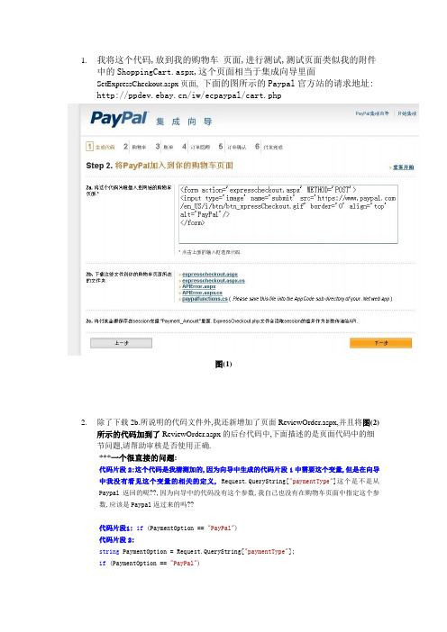
1.我将这个代码,放到我的购物车页面,进行测试,测试页面类似我的附件中的ShoppingCart.aspx,这个页面相当于集成向导里面SetExpressCheckout.aspx页面,下面的图所示的Paypal官方站的请求地址: /iw/ecpaypal/cart.php图(1)2.除了下载2b.所说明的代码文件外,我还新增加了页面ReviewOrder.aspx,并且将图(2)所示的代码加到了ReviewOrder.aspx的后台代码中,下面描述的是页面代码中的细节问题,请帮助审核是否使用正确.***一个很直接的问题:代码片段2:这个代码是我猜测加的,因为向导中生成的代码片段1中需要这个变量,但是在向导中我没有看见这个变量的相关的定义, Request.QueryString["paymentType"]这个是不是从Paypal返回的呢??,因为向导中的代码没有这个参数,我自己也没有在购物车页面中指定这个参数,应该是Paypal返过来的吗??代码片段1: if (PaymentOption == "PayPal")代码片段2:string PaymentOption = Request.QueryString["paymentType"];if (PaymentOption == "PayPal")图(2)3.根据说明这个Revieworder.aspx被调用了两次,第一次是客户提交购物车的时候,第二次是通过Token值,回取客户的详细运输地址的时候,所以我将如下代码写在了后台中,如果有Token值的条件分支中:如下代码,集成向导中的代码截图如图(3)示;这个送货物地址是不是需要用Write()方法将信息全部写到或者添加到Revieworder.aspx这个页面供用户核对呢?另外如果是免运费的是不是不需要指定运费的那个参数就可以了,还是说需要指定一个特定的值呢图(3)if (PaymentOption == "PayPal"){NVPAPICaller test = new NVPAPICaller();string retMsg = "";string token = "";string payerId = "";string shippingAddress = "";token = Session["token"].ToString();bool ret = test.GetShippingDetails(token, ref payerId, ref shippingAddress, ref retMsg); if (ret){Session["payerId"] = payerId;Response.Write(shippingAddress);}else{Response.Redirect("APIError.aspx?" + retMsg);}}4.我增加了一个新页面: DoExpressCheckoutPayment.aspx,确认付款页面,请问放置客户的收货地址是在这个页面,还是在上面的ReviewOrder.aspx页面呢,向导代码截图如图(4),在这个确定付款页面,写定单信息到数据库合适吗?如果我使用IPN来处理,那么和通用的付款方式会有区别那么我可以通过参数<input type="hidden"name="notify_url" value="/PaypalValide.aspx" />设置不同的通知地址,这样来分别处理不同的结帐方式,而来操作数据库的定单信息吗图(4)附件的代码是我根据向导猜测写的一个测试网站,请帮助核对是否有问题,非常谢谢,顺祝工作愉快!。
3GPP协议-36521-1-e40_s00-s05
3GPP TS 36.521-1 V14.4.0 (2017-09)Technical Specification3rd Generation Partnership Project; Technical Specification Group Radio Access Network; Evolved Universal Terrestrial Radio Access (E-UTRA);User Equipment (UE) conformance specification;Radio transmission and reception;Part 1: Conformance Testing(Release 14)The present document has been developed within the 3rd Generation Partnership Project (3GPP TM) and may be further elaborated for the purposes of 3GPP.KeywordsUMTS LTE3GPPPostal address3GPP support office address650 Route des Lucioles - Sophia AntipolisValbonne - FRANCETel.: +33 4 92 94 42 00 Fax: +33 4 93 65 47 16InternetCopyright NotificationNo part may be reproduced except as authorized by written permission.The copyright and the foregoing restriction extend to reproduction in all media.© 2017, 3GPP Organizational Partners (ARIB, ATIS, CCSA, ETSI, TSDSI, TTA, TTC).All rights reserved.UMTS™ is a Trade Mark of ETSI registered for the benefit of its members3GPP™ is a Trade Mark of ETSI registered for the benefit of its Members and of the 3GPP Organizational Partners LTE™ is a Trade Mark of ETSI registered for the benefit of its Members a nd of the 3GPP Organizational Partners GSM® and the GSM logo are registered and owned by the GSM AssociationContentsForeword (92)Introduction (92)1Scope (93)2References (94)3Definitions, symbols and abbreviations (96)3.1Definitions (96)3.2Symbols (98)3.3Abbreviations (100)4General (103)4.1Categorization of test requirements in CA, UL-MIMO, ProSe, Dual Connectivity, UE category 0, UEcategory M1, UE category 1bis, UE category NB1 and V2X Communication (104)4.2RF requirements in later releases (105)5Frequency bands and channel arrangement (106)5.1General (106)5.2Operating bands (106)5.2A Operating bands for CA (108)5.2B Operating bands for UL-MIMO (116)5.2C Operating bands for Dual Connectivity (116)5.2D Operating bands for ProSe (117)5.2E Operating bands for UE category 0 and UE category M1 (118)5.2F Operating bands for UE category NB1 (118)5.2G Operating bands for V2X Communication (118)5.3TX–RX frequency separation (119)5.3A TX–RX frequency separation for CA (120)5.4Channel arrangement (120)5.4.1Channel spacing (120)5.4.1A Channel spacing for CA (121)5.4.1F Channel spacing for UE category NB1 (121)5.4.2Channel bandwidth (121)5.4.2.1Channel bandwidths per operating band (122)5.4.2A Channel bandwidth for CA (124)5.4.2A.1Channel bandwidths per operating band for CA (126)5.4.2B Channel bandwidth for UL-MIMO (171)5.4.2B.1Channel bandwidths per operating band for UL- MIMO (171)5.4.2C Channel bandwidth for Dual Connectivity (171)5.4.2D Channel bandwidth for ProSe (171)5.4.2D.1Channel bandwidths per operating band for ProSe (171)5.4.2F Channel bandwidth for category NB1 (172)5.4.2G Channel bandwidth for V2X Communication (173)5.4.2G.1Channel bandwidths per operating band for V2X Communication (173)5.4.3Channel raster (174)5.4.3A Channel raster for CA (175)5.4.3F Channel raster for UE category NB1 (175)5.4.4Carrier frequency and EARFCN (175)5.4.4F Carrier frequency and EARFCN for category NB1 (177)6Transmitter Characteristics (179)6.1General (179)6.2Transmit power (180)6.2.1Void (180)6.2.2UE Maximum Output Power (180)6.2.2.1Test purpose (180)6.2.2.4Test description (182)6.2.2.4.1Initial condition (182)6.2.2.4.2Test procedure (183)6.2.2.4.3Message contents (183)6.2.2.5Test requirements (183)6.2.2_1Maximum Output Power for HPUE (185)6.2.2_1.1Test purpose (185)6.2.2_1.2Test applicability (185)6.2.2_1.3Minimum conformance requirements (185)6.2.2_1.4Test description (185)6.2.2_1.5Test requirements (186)6.2.2A UE Maximum Output Power for CA (187)6.2.2A.0Minimum conformance requirements (187)6.2.2A.1UE Maximum Output Power for CA (intra-band contiguous DL CA and UL CA) (189)6.2.2A.1.1Test purpose (189)6.2.2A.1.2Test applicability (189)6.2.2A.1.3Minimum conformance requirements (189)6.2.2A.1.4Test description (189)6.2.2A.1.5Test Requirements (191)6.2.2A.2UE Maximum Output Power for CA (inter-band DL CA and UL CA) (192)6.2.2A.2.1Test purpose (192)6.2.2A.2.2Test applicability (192)6.2.2A.2.3Minimum conformance requirements (192)6.2.2A.2.4Test description (192)6.2.2A.2.5Test Requirements (194)6.2.2A.3UE Maximum Output Power for CA (intra-band non-contiguous DL CA and UL CA) (196)6.2.2A.4.1UE Maximum Output Power for CA (intra-band contiguous 3DL CA and 3UL CA) (196)6.2.2A.4.1.1Test purpose (196)6.2.2A.4.1.2Test applicability (196)6.2.2A.4.1.3Minimum conformance requirements (196)6.2.2A.4.1.4Test description (196)6.2.2A.4.1.5Test Requirements (198)6.2.2A.4.2UE Maximum Output Power for CA (inter-band 3DL CA and 3UL CA) (198)6.2.2A.4.2.1Test purpose (199)6.2.2A.4.2.2Test applicability (199)6.2.2A.4.2.3Minimum conformance requirements (199)6.2.2A.4.2.4Test description (199)6.2.2A.4.2.5Test Requirements (201)6.2.2B UE Maximum Output Power for UL-MIMO (201)6.2.2B.1Test purpose (201)6.2.2B.2Test applicability (202)6.2.2B.3Minimum conformance requirements (202)6.2.2B.4Test description (204)6.2.2B.4.1Initial condition (204)6.2.2B.4.2Test procedure (205)6.2.2B.4.3Message contents (205)6.2.2B.5Test requirements (205)6.2.2B_1HPUE Maximum Output Power for UL-MIMO (207)6.2.2B_1.1Test purpose (207)6.2.2B_1.2Test applicability (207)6.2.2B_1.3Minimum conformance requirements (207)6.2.2B_1.4Test description (207)6.2.2B_1.5Test requirements (208)6.2.2C 2096.2.2D UE Maximum Output Power for ProSe (209)6.2.2D.0Minimum conformance requirements (209)6.2.2D.1UE Maximum Output Power for ProSe Discovery (209)6.2.2D.1.1Test purpose (209)6.2.2D.1.2Test applicability (209)6.2.2D.1.3Minimum Conformance requirements (209)6.2.2D.2UE Maximum Output Power for ProSe Direct Communication (211)6.2.2D.2.1Test purpose (211)6.2.2D.2.2Test applicability (211)6.2.2D.2.3Minimum conformance requirements (211)6.2.2D.2.4Test description (211)6.2.2E UE Maximum Output Power for UE category 0 (212)6.2.2E.1Test purpose (212)6.2.2E.2Test applicability (212)6.2.2E.3Minimum conformance requirements (212)6.2.2E.4Test description (212)6.2.2E.4.3Message contents (213)6.2.2E.5Test requirements (213)6.2.2EA UE Maximum Output Power for UE category M1 (215)6.2.2EA.1Test purpose (215)6.2.2EA.2Test applicability (215)6.2.2EA.3Minimum conformance requirements (215)6.2.2EA.4Test description (216)6.2.2EA.4.3Message contents (217)6.2.2EA.5Test requirements (217)6.2.2F UE Maximum Output Power for category NB1 (218)6.2.2F.1Test purpose (218)6.2.2F.2Test applicability (218)6.2.2F.3Minimum conformance requirements (218)6.2.2F.4Test description (219)6.2.2F.4.1Initial condition (219)6.2.2F.4.2Test procedure (220)6.2.2F.4.3Message contents (220)6.2.2F.5Test requirements (220)6.2.2G UE Maximum Output Power for V2X Communication (221)6.2.2G.1UE Maximum Output Power for V2X Communication / Non-concurrent with E-UTRA uplinktransmission (221)6.2.2G.1.1Test purpose (221)6.2.2G.1.2Test applicability (221)6.2.2G.1.3Minimum conformance requirements (221)6.2.2G.1.4Test description (222)6.2.2G.1.4.1Initial conditions (222)6.2.2G.1.4.2Test procedure (222)6.2.2G.1.4.3Message contents (222)6.2.2G.1.5Test requirements (223)6.2.2G.2UE Maximum Output Power for V2X Communication / Simultaneous E-UTRA V2X sidelinkand E-UTRA uplink transmission (223)6.2.2G.2.1Test purpose (223)6.2.2G.2.2Test applicability (223)6.2.2G.2.3Minimum conformance requirements (223)6.2.2G.2.4Test description (224)6.2.2G.2.4.1Initial conditions (224)6.2.2G.2.4.2Test procedure (225)6.2.2G.2.4.3Message contents (226)6.2.2G.2.5Test requirements (226)6.2.3Maximum Power Reduction (MPR) (226)6.2.3.1Test purpose (226)6.2.3.2Test applicability (226)6.2.3.3Minimum conformance requirements (227)6.2.3.4Test description (227)6.2.3.4.1Initial condition (227)6.2.3.4.2Test procedure (228)6.2.3.4.3Message contents (228)6.2.3.5Test requirements (229)6.2.3_1Maximum Power Reduction (MPR) for HPUE (231)6.2.3_1.1Test purpose (231)6.2.3_1.4Test description (232)6.2.3_1.5Test requirements (232)6.2.3_2Maximum Power Reduction (MPR) for Multi-Cluster PUSCH (232)6.2.3_2.1Test purpose (232)6.2.3_2.2Test applicability (232)6.2.3_2.3Minimum conformance requirements (233)6.2.3_2.4Test description (233)6.2.3_2.4.1Initial condition (233)6.2.3_2.4.2Test procedure (234)6.2.3_2.4.3Message contents (234)6.2.3_2.5Test requirements (234)6.2.3_3Maximum Power Reduction (MPR) for UL 64QAM (235)6.2.3_3.1Test purpose (236)6.2.3_3.2Test applicability (236)6.2.3_3.3Minimum conformance requirements (236)6.2.3_3.4Test description (236)6.2.3_3.4.1Initial condition (236)6.2.3_3.4.2Test procedure (237)6.2.3_3.4.3Message contents (237)6.2.3_3.5Test requirements (238)6.2.3_4Maximum Power Reduction (MPR) for Multi-Cluster PUSCH with UL 64QAM (240)6.2.3_4.1Test purpose (240)6.2.3_4.2Test applicability (240)6.2.3_4.3Minimum conformance requirements (240)6.2.3_4.4Test description (241)6.2.3_4.4.1Initial condition (241)6.2.3_4.4.2Test procedure (242)6.2.3_4.4.3Message contents (242)6.2.3_4.5Test requirements (242)6.2.3A Maximum Power Reduction (MPR) for CA (243)6.2.3A.1Maximum Power Reduction (MPR) for CA (intra-band contiguous DL CA and UL CA) (243)6.2.3A.1.1Test purpose (243)6.2.3A.1.2Test applicability (243)6.2.3A.1.3Minimum conformance requirements (244)6.2.3A.1.4Test description (245)6.2.3A.1.5Test Requirements (248)6.2.3A.1_1Maximum Power Reduction (MPR) for CA (intra-band contiguous DL CA and UL CA) for UL64QAM (250)6.2.3A.1_1.1Test purpose (251)6.2.3A.1_1.2Test applicability (251)6.2.3A.1_1.3Minimum conformance requirements (251)6.2.3A.1_1.4Test description (252)6.2.3A.1_1.5Test requirement (254)6.2.3A.2Maximum Power Reduction (MPR) for CA (inter-band DL CA and UL CA) (255)6.2.3A.2.1Test purpose (255)6.2.3A.2.2Test applicability (255)6.2.3A.2.3Minimum conformance requirements (255)6.2.3A.2.4Test description (256)6.2.3A.2.5Test Requirements (260)6.2.3A.2_1Maximum Power Reduction (MPR) for CA (inter-band DL CA and UL CA) for UL 64QAM (263)6.2.3A.2_1.1Test purpose (263)6.2.3A.2_1.2Test applicability (263)6.2.3A.2_1.3Minimum conformance requirements (263)6.2.3A.2_1.4Test description (264)6.2.3A.2_1.5Test Requirements (266)6.2.3A.3Maximum Power Reduction (MPR) for CA (intra-band non-contiguous DL CA and UL CA) (267)6.2.3A.3.1Test purpose (267)6.2.3A.3.2Test applicability (267)6.2.3A.3.3Minimum conformance requirements (268)6.2.3A.3.4Test description (268)6.2.3A.3_1Maximum Power Reduction (MPR) for CA (intra-band non-contiguous DL CA and UL CA) forUL 64QAM (270)6.2.3A.3_1.1Test purpose (270)6.2.3A.3_1.2Test applicability (270)6.2.3A.3_1.3Minimum conformance requirements (270)6.2.3A.3_1.4Test description (271)6.2.3A.3_1.5Test Requirements (272)6.2.3B Maximum Power Reduction (MPR) for UL-MIMO (272)6.2.3B.1Test purpose (272)6.2.3B.2Test applicability (272)6.2.3B.3Minimum conformance requirements (273)6.2.3B.4Test description (273)6.2.3B.4.1Initial condition (273)6.2.3B.4.2Test procedure (274)6.2.3B.4.3Message contents (275)6.2.3B.5Test requirements (275)6.2.3D UE Maximum Output Power for ProSe (277)6.2.3D.0Minimum conformance requirements (277)6.2.3D.1Maximum Power Reduction (MPR) for ProSe Discovery (278)6.2.3D.1.1Test purpose (278)6.2.3D.1.2Test applicability (278)6.2.3D.1.3Minimum conformance requirements (278)6.2.3D.1.4Test description (278)6.2.3D.1.4.1Initial condition (278)6.2.3D.1.4.2Test procedure (279)6.2.3D.1.4.3Message contents (279)6.2.3D.1.5Test requirements (280)6.2.3D.2Maximum Power Reduction (MPR) ProSe Direct Communication (281)6.2.3D.2.1Test purpose (282)6.2.3D.2.2Test applicability (282)6.2.3D.2.3Minimum conformance requirements (282)6.2.3D.2.4Test description (282)6.2.3D.2.4.1Initial conditions (282)6.2.3D.2.4.2Test procedure (282)6.2.3D.2.4.3Message contents (282)6.2.3D.2.5Test requirements (282)6.2.3E Maximum Power Reduction (MPR) for UE category 0 (282)6.2.3E.1Test purpose (282)6.2.3E.2Test applicability (282)6.2.3E.3Minimum conformance requirements (282)6.2.3E.4Test description (282)6.2.3E.4.1Initial condition (282)6.2.3E.4.2Test procedure (283)6.2.3E.4.3Message contents (283)6.2.3E.5Test requirements (283)6.2.3EA Maximum Power Reduction (MPR) for UE category M1 (284)6.2.3EA.1Test purpose (284)6.2.3EA.2Test applicability (284)6.2.3EA.3Minimum conformance requirements (284)6.2.3EA.4Test description (285)6.2.3EA.4.1Initial condition (285)6.2.3EA.4.2Test procedure (287)6.2.3EA.4.3Message contents (287)6.2.3EA.5Test requirements (287)6.2.3F Maximum Power Reduction (MPR) for category NB1 (290)6.2.3F.1Test purpose (290)6.2.3F.2Test applicability (290)6.2.3F.3Minimum conformance requirements (290)6.2.3F.4Test description (291)6.2.3F.4.1Initial condition (291)6.2.3F.5Test requirements (292)6.2.3G Maximum Power Reduction (MPR) for V2X communication (292)6.2.3G.1Maximum Power Reduction (MPR) for V2X Communication / Power class 3 (293)6.2.3G.1.1Maximum Power Reduction (MPR) for V2X Communication / Power class 3 / Contiguousallocation of PSCCH and PSSCH (293)6.2.3G.1.1.1Test purpose (293)6.2.3G.1.1.2Test applicability (293)6.2.3G.1.1.3Minimum conformance requirements (293)6.2.3G.1.1.4Test description (293)6.2.3G.1.1.4.1Initial condition (293)6.2.3G.1.1.4.2Test procedure (294)6.2.3G.1.1.4.3Message contents (294)6.2.3G.1.1.5Test Requirements (294)6.2.3G.1.2 2956.2.3G.1.3Maximum Power Reduction (MPR) for V2X Communication / Power class 3 / SimultaneousE-UTRA V2X sidelink and E-UTRA uplink transmission (295)6.2.3G.1.3.1Test purpose (295)6.2.3G.1.3.2Test applicability (295)6.2.3G.1.3.3Minimum conformance requirements (295)6.2.3G.1.3.4Test description (295)6.2.3G.1.3.4.1Initial conditions (295)6.2.3G.1.3.4.2Test procedure (296)6.2.3G.1.3.4.3Message contents (297)6.2.3G.1.3.5Test requirements (297)6.2.4Additional Maximum Power Reduction (A-MPR) (297)6.2.4.1Test purpose (297)6.2.4.2Test applicability (297)6.2.4.3Minimum conformance requirements (298)6.2.4.4Test description (310)6.2.4.4.1Initial condition (310)6.2.4.4.2Test procedure (339)6.2.4.4.3Message contents (339)6.2.4.5Test requirements (344)6.2.4_1Additional Maximum Power Reduction (A-MPR) for HPUE (373)6.2.4_1.2Test applicability (374)6.2.4_1.3Minimum conformance requirements (374)6.2.4_1.4Test description (375)6.2.4_1.5Test requirements (376)6.2.4_2Additional Maximum Power Reduction (A-MPR) for UL 64QAM (378)6.2.4_2.1Test purpose (378)6.2.4_2.2Test applicability (378)6.2.4_2.3Minimum conformance requirements (378)6.2.4_2.4Test description (378)6.2.4_2.4.1Initial condition (378)6.2.4_2.4.2Test procedure (392)6.2.4_2.4.3Message contents (392)6.2.4_2.5Test requirements (392)6.2.4_3Additional Maximum Power Reduction (A-MPR) with PUSCH frequency hopping (404)6.2.4_3.1Test purpose (404)6.2.4_3.2Test applicability (404)6.2.4_3.3Minimum conformance requirements (405)6.2.4_3.4Test description (405)6.2.4_3.5Test requirements (406)6.2.4A Additional Maximum Power Reduction (A-MPR) for CA (407)6.2.4A.1Additional Maximum Power Reduction (A-MPR) for CA (intra-band contiguous DL CA and ULCA) (407)6.2.4A.1.1Test purpose (407)6.2.4A.1.2Test applicability (407)6.2.4A.1.3Minimum conformance requirements (407)6.2.4A.1.3.5A-MPR for CA_NS_05 for CA_38C (411)6.2.4A.1.4Test description (413)6.2.4A.1.5Test requirements (419)6.2.4A.1_1Additional Maximum Power Reduction (A-MPR) for CA (intra-band contiguous DL CA and ULCA) for UL 64QAM (425)6.2.4A.1_1.1Test purpose (425)6.2.4A.1_1.2Test applicability (425)6.2.4A.1_1.3Minimum conformance requirements (426)6.2.4A.1_1.3.5A-MPR for CA_NS_05 for CA_38C (429)6.2.4A.1_1.3.6A-MPR for CA_NS_06 for CA_7C (430)6.2.4A.1_1.3.7A-MPR for CA_NS_07 for CA_39C (431)6.2.4A.1_1.3.8A-MPR for CA_NS_08 for CA_42C (432)6.2.4A.1_1.4Test description (432)6.2.4A.1_1.5Test requirements (437)6.2.4A.2Additional Maximum Power Reduction (A-MPR) for CA (inter-band DL CA and UL CA) (443)6.2.4A.2.1Test purpose (443)6.2.4A.2.2Test applicability (444)6.2.4A.2.3Minimum conformance requirements (444)6.2.4A.2.4Test description (444)6.2.4A.2.4.1Initial conditions (444)6.2.4A.2.4.2Test procedure (457)6.2.4A.2.4.3Message contents (458)6.2.4A.2.5Test requirements (461)6.2.4A.3Additional Maximum Power Reduction (A-MPR) for CA (intra-band non-contiguous DL CAand UL CA) (466)6.2.4A.3.1Minimum conformance requirements (466)6.2.4A.2_1Additional Maximum Power Reduction (A-MPR) for CA (inter-band DL CA and UL CA) forUL 64QAM (466)6.2.4A.2_1.1Test purpose (466)6.2.4A.2_1.2Test applicability (466)6.2.4A.2_1.3Minimum conformance requirements (467)6.2.4A.2_1.4Test description (467)6.2.4A.2_1.4.1Initial conditions (467)6.2.4A.2_1.4.2Test procedure (479)6.2.4A.2_1.4.3Message contents (480)6.2.4A.2_1.5Test requirements (480)6.2.4B Additional Maximum Power Reduction (A-MPR) for UL-MIMO (484)6.2.4B.1Test purpose (484)6.2.4B.2Test applicability (485)6.2.4B.3Minimum conformance requirements (485)6.2.4B.4Test description (485)6.2.4B.4.1Initial condition (485)6.2.4B.4.2Test procedure (508)6.2.4B.4.3Message contents (508)6.2.4B.5Test requirements (508)6.2.4E Additional Maximum Power Reduction (A-MPR) for UE category 0 (530)6.2.4E.1Test purpose (530)6.2.4E.2Test applicability (531)6.2.4E.3Minimum conformance requirements (531)6.2.4E.4Test description (531)6.2.4E.4.1Initial condition (531)6.2.4E.4.2Test procedure (535)6.2.4E.4.3Message contents (535)6.2.4E.5Test requirements (536)6.2.4EA Additional Maximum Power Reduction (A-MPR) for UE category M1 (542)6.2.4EA.1Test purpose (542)6.2.4EA.2Test applicability (542)6.2.4EA.3Minimum conformance requirements (543)6.2.4EA.4Test description (544)6.2.4EA.4.1Initial condition (544)6.2.4EA.4.2Test procedure (552)6.2.4G Additional Maximum Power Reduction (A-MPR) for V2X Communication (562)6.2.4G.1Additional Maximum Power Reduction (A-MPR) for V2X Communication / Non-concurrentwith E-UTRA uplink transmissions (562)6.2.4G.1.1Test purpose (562)6.2.4G.1.2Test applicability (562)6.2.4G.1.3Minimum conformance requirements (563)6.2.4G.1.4Test description (563)6.2.4G.1.4.1Initial condition (563)6.2.4G.1.4.2Test procedure (564)6.2.4G.1.4.3Message contents (564)6.2.4G.1.5Test Requirements (564)6.2.5Configured UE transmitted Output Power (564)6.2.5.1Test purpose (564)6.2.5.2Test applicability (564)6.2.5.3Minimum conformance requirements (564)6.2.5.4Test description (594)6.2.5.4.1Initial conditions (594)6.2.5.4.2Test procedure (595)6.2.5.4.3Message contents (595)6.2.5.5Test requirement (596)6.2.5_1Configured UE transmitted Output Power for HPUE (596)6.2.5_1.1Test purpose (596)6.2.5_1.2Test applicability (597)6.2.5_1.3Minimum conformance requirements (597)6.2.5_1.4Test description (597)6.2.5_1.4.1Initial conditions (597)6.2.5_1.4.2Test procedure (597)6.2.5_1.4.3Message contents (597)6.2.5_1.5Test requirement (598)6.2.5A Configured transmitted power for CA (599)6.2.5A.1Configured UE transmitted Output Power for CA (intra-band contiguous DL CA and UL CA) (599)6.2.5A.1.1Test purpose (599)6.2.5A.1.2Test applicability (599)6.2.5A.1.3Minimum conformance requirements (599)6.2.5A.1.4Test description (601)6.2.5A.1.5Test requirement (602)6.2.5A.2Void (603)6.2.5A.3Configured UE transmitted Output Power for CA (inter-band DL CA and UL CA) (603)6.2.5A.3.1Test purpose (603)6.2.5A.3.2Test applicability (603)6.2.5A.3.3Minimum conformance requirements (603)6.2.5A.3.4Test description (605)6.2.5A.3.5Test requirement (606)6.2.5A.4Configured UE transmitted Output Power for CA (intra-band non-contiguous DL CA and ULCA) (607)6.2.5A.4.1Test purpose (607)6.2.5A.4.2Test applicability (607)6.2.5A.4.3Minimum conformance requirements (607)6.2.5A.4.4Test description (608)6.2.5A.4.5Test requirement (610)6.2.5B Configured UE transmitted Output Power for UL-MIMO (611)6.2.5B.1Test purpose (611)6.2.5B.2Test applicability (611)6.2.5B.3Minimum conformance requirements (611)6.2.5B.4Test description (612)6.2.5B.4.1Initial conditions (612)6.2.5B.4.2Test procedure (612)6.2.5B.4.3Message contents (613)6.2.5B.5Test requirement (613)6.2.5E Configured UE transmitted Output Power for UE category 0 (614)6.2.5E.4.1Initial conditions (614)6.2.5E.4.2Test procedure (614)6.2.5E.4.3Message contents (614)6.2.5E.5Test requirement (615)6.2.5EA Configured UE transmitted Power for UE category M1 (615)6.2.5EA.1Test purpose (615)6.2.5EA.2Test applicability (615)6.2.5EA.3Minimum conformance requirements (615)6.2.5EA.4Test description (616)6.2.5EA.4.1Initial condition (616)6.2.5EA.4.2Test procedure (617)6.2.5EA.4.3Message contents (617)6.2.5EA.5Test requirements (617)6.2.5F Configured UE transmitted Output Power for UE category NB1 (618)6.2.5F.1Test purpose (618)6.2.5F.2Test applicability (618)6.2.5F.3Minimum conformance requirements (618)6.2.5F.4Test description (619)6.2.5F.4.1Initial conditions (619)6.2.5F.4.2Test procedure (620)6.2.5F.4.3Message contents (620)6.2.5F.5Test requirement (620)6.2.5G Configured UE transmitted Output Power for V2X Communication (620)6.2.5G.1Configured UE transmitted Output Power for V2X Communication / Non-concurrent with E-UTRA uplink transmission (621)6.2.5G.1.1Test purpose (621)6.2.5G.1.2Test applicability (621)6.2.5G.1.3Minimum conformance requirements (621)6.2.5G.1.4Test description (622)6.2.5G.1.4.1Initial conditions (622)6.2.5G.1.4.2Test procedure (622)6.2.5G.1.4.3Message contents (622)6.2.5G.1.5Test requirements (622)6.2.5G.2Configured UE transmitted Output Power for V2X Communication / Simultaneous E-UTRAV2X sidelink and E-UTRA uplink transmission (622)6.2.5G.2.1Test purpose (623)6.2.5G.2.2Test applicability (623)6.2.5G.2.3Minimum conformance requirements (623)6.2.5G.2.4Test description (625)6.2.5G.2.4.1Initial conditions (625)6.2.5G.2.4.2Test procedure (626)6.2.5G.2.4.3Message contents (626)6.2.5G.2.5Test requirements (626)6.3Output Power Dynamics (627)6.3.1Void (627)6.3.2Minimum Output Power (627)6.3.2.1Test purpose (627)6.3.2.2Test applicability (627)6.3.2.3Minimum conformance requirements (627)6.3.2.4Test description (627)6.3.2.4.1Initial conditions (627)6.3.2.4.2Test procedure (628)6.3.2.4.3Message contents (628)6.3.2.5Test requirement (628)6.3.2A Minimum Output Power for CA (629)6.3.2A.0Minimum conformance requirements (629)6.3.2A.1Minimum Output Power for CA (intra-band contiguous DL CA and UL CA) (629)6.3.2A.1.1Test purpose (629)6.3.2A.1.4.2Test procedure (631)6.3.2A.1.4.3Message contents (631)6.3.2A.1.5Test requirements (631)6.3.2A.2Minimum Output Power for CA (inter-band DL CA and UL CA) (631)6.3.2A.2.1Test purpose (631)6.3.2A.2.2Test applicability (632)6.3.2A.2.3Minimum conformance requirements (632)6.3.2A.2.4Test description (632)6.3.2A.2.4.1Initial conditions (632)6.3.2A.2.4.2Test procedure (633)6.3.2A.2.4.3Message contents (633)6.3.2A.2.5Test requirements (633)6.3.2A.3Minimum Output Power for CA (intra-band non-contiguous DL CA and UL CA) (634)6.3.2A.3.1Test purpose (634)6.3.2A.3.2Test applicability (634)6.3.2A.3.3Minimum conformance requirements (634)6.3.2A.3.4Test description (634)6.3.2A.3.4.1Initial conditions (634)6.3.2A.3.4.2Test procedure (635)6.3.2A.3.4.3Message contents (635)6.3.2A.3.5Test requirements (635)6.3.2B Minimum Output Power for UL-MIMO (636)6.3.2B.1Test purpose (636)6.3.2B.2Test applicability (636)6.3.2B.3Minimum conformance requirements (636)6.3.2B.4Test description (636)6.3.2B.4.1Initial conditions (636)6.3.2B.4.2Test procedure (637)6.3.2B.4.3Message contents (637)6.3.2B.5Test requirement (637)6.3.2E Minimum Output Power for UE category 0 (638)6.3.2E.1Test purpose (638)6.3.2E.2Test applicability (638)6.3.2E.3Minimum conformance requirements (638)6.3.2E.4Test description (638)6.3.2E.4.1Initial conditions (638)6.3.2E.4.2Test procedure (639)6.3.2E.4.3Message contents (639)6.3.2E.5Test requirement (639)6.3.2EA Minimum Output Power for UE category M1 (639)6.3.2EA.1Test purpose (639)6.3.2EA.2Test applicability (640)6.3.2EA.3Minimum conformance requirements (640)6.3.2EA.4Test description (640)6.3.2EA.4.1Initial condition (640)6.3.2EA.4.2Test procedure (641)6.3.2EA.4.3Message contents (641)6.3.2EA.5Test requirements (641)6.3.2F Minimum Output Power for category NB1 (641)6.3.2F.1Test purpose (641)6.3.2F.2Test applicability (641)6.3.2F.3Minimum conformance requirements (642)6.3.2F.4Test description (642)6.3.2F.4.1Initial conditions (642)6.3.2F.4.2Test procedure (643)6.3.2F.4.3Message contents (643)6.3.2F.5Test requirements (643)6.3.3Transmit OFF power (643)6.3.3.5Test requirement (644)6.3.3A UE Transmit OFF power for CA (644)6.3.3A.0Minimum conformance requirements (644)6.3.3A.1UE Transmit OFF power for CA (intra-band contiguous DL CA and UL CA) (645)6.3.3A.1.1Test purpose (645)6.3.3A.1.2Test applicability (645)6.3.3A.1.3Minimum conformance requirements (645)6.3.3A.1.4Test description (645)6.3.3A.1.5Test Requirements (645)6.3.3A.2UE Transmit OFF power for CA (inter-band DL CA and UL CA) (646)6.3.3A.2.1Test purpose (646)6.3.3A.2.2Test applicability (646)6.3.3A.2.3Minimum conformance requirements (646)6.3.3A.2.4Test description (646)6.3.3A.2.5Test Requirements (646)6.3.3A.3UE Transmit OFF power for CA (intra-band non-contiguous DL CA and UL CA) (646)6.3.3A.3.1Test purpose (646)6.3.3A.3.2Test applicability (646)6.3.3A.3.3Minimum conformance requirements (647)6.3.3A.3.4Test description (647)6.3.3A.3.5Test Requirements (647)6.3.3B UE Transmit OFF power for UL-MIMO (647)6.3.3B.1Test purpose (647)6.3.3B.2Test applicability (647)6.3.3B.3Minimum conformance requirement (647)6.3.3B.4Test description (647)6.3.3B.5Test requirement (648)6.3.3C 6486.3.3D UE Transmit OFF power for ProSe (648)6.3.3D.0Minimum conformance requirements (648)6.3.3D.1UE Transmit OFF power for ProSe Direct Discovery (648)6.3.3D.1.1Test purpose (649)6.3.3D.1.2Test applicability (649)6.3.3D.1.3Minimum Conformance requirements (649)6.3.3D.1.4Test description (649)6.3.3D.1.5Test requirements (650)6.3.3E UE Transmit OFF power for UE category 0 (650)6.3.3E.1Test purpose (650)6.3.3E.2Test applicability (650)6.3.3E.3Minimum conformance requirement (650)6.3.3E.4Test description (651)6.3.3E.5Test requirement (651)6.3.3EA UE Transmit OFF power for UE category M1 (651)6.3.3EA.1Test purpose (651)6.3.3EA.2Test applicability (651)6.3.3EA.3Minimum conformance requirements (651)6.3.3EA.4Test description (651)6.3.3EA.5Test requirements (652)6.3.3F Transmit OFF power for category NB1 (652)6.3.3F.1Test purpose (652)6.3.3F.2Test applicability (652)6.3.3F.3Minimum conformance requirement (652)6.3.3F.4Test description (652)6.3.3F.5Test requirement (652)6.3.4ON/OFF time mask (652)6.3.4.1General ON/OFF time mask (652)6.3.4.1.1Test purpose (652)6.3.4.1.2Test applicability (653)。
IBM Cognos 软件开发工具包版本 11.0.0 混搭服务开发人员指南说明书
Java samples..............................................................................................................................................11 Java sample file locations.................................................................................................................... 11 Running the Java samples................................................................................................................... 12
Chapter 2. Overview of the Mashup Service............................................................ 7
Programming interfaces...............................................................................................................................7 Identifying reports....................................................................................................................................... 8 Output formats.............................................................................................................................................9 Sample programs.......................................................................................................................................10
BulkOnly协议

Universal Serial Bus Mass Storage Class Bulk-Only TransportRevision 1.0September 31, 1999Change HistoryRevision Issue Date Comments0.7September 23, 1998Initial draft, pre-release0.8October 6, 1998Revisions made at the Mass Storage DWG review – Irvine, CA0.9October 21, 1998Revisions made at the Mass Storage DWG review – Plano, TX0.9a January 5, 1999Revisions made at the Mass Storage DWG review – Tigard, OR0.9b February 1, 1999Additions of LUN support - Milpitas, CA1.0[RC1]March 5, 1999RR review - Midway, UT1.0[RC2]March 23, 1999Revisions from reflector review comments1.0[RC3]March 29, 1999Specification line by line review – Milpitas, CA1.0[RC4]June 21, 1999Specification line by line review – RR21 – Milpitas, CA1.0September 31, 1999Final Revision edits for Released Document – SLC, UTUSB Device Class Definition for Mass Storage DevicesCopyright © 1998, 1999, USB Implementers Forum.All rights reserved.INTELLECTUAL PROPERTY DISCLAIMERTHIS SPECIFICATION IS PROVIDED “AS IS” WITH NO WARRANTIES WHATSOEVER INCLUDING ANY WARRANTY OF MERCHANTABILITY, FITNESS FOR ANY PARTICULAR PURPOSE, OR ANY WARRANTY OTHERWISE ARISING OUT OF ANY PROPOSAL, SPECIFICATION, OR SAMPLE.A LICENSE IS HEREBY GRANTED TO REPRODUCE AND DISTRIBUTE THIS SPECIFICATION FOR INTERNAL USE ONLY. NO OTHER LICENSE, EXPRESS OR IMPLIED, BY ESTOPPEL OR OTHERWISE, TO ANY OTHER INTELLECTUAL PROPERTY RIGHTS IS GRANTED OR INTENDED HEREBY.AUTHORS OF THIS SPECIFICATION DISCLAIM ALL LIABILITY, INCLUDING LIABILITY FOR INFRINGEMENT OF PROPRIETARY RIGHTS, RELATING TO IMPLEMENTATION OF INFORMATION IN THIS SPECIFICATION. AUTHORS OF THIS SPECIFICATION ALSO DO NOT WARRANT OR REPRESENT THAT SUCH IMPLEMENTATION(S) WILL NOT INFRINGE SUCH RIGHTS.ContributorsAl Rickey, Phoenix TechnologiesAlan Haffner, Lexar MediaBill Stanley, AdaptecCalaimany Bhoopathi, Shuttle TechnologyCurtis E. Stevens, Phoenix TechnologiesDarrell Redford , Iomega CorporationDave Gilbert, In-System DesignDavid G. Lawrence, Global Technology Development David L. Jolley, Iomega CorporationDavid Luke, In-System DesignEric Luttman, In-System DesignGlen Slick, Microsoft CorporationHiromichi Oribe, Hagiwara Sys-ComCoJan Matejica, PIMC/PhilipsJim Blackson, Y-E Data, IncJim Quigley, Iomega CorporationJohan Craeybeckk, PIMC/PhilipsJordan Brown, Sun MicrosystemsKenny Chu, Hagiwara Sys-ComCoKenichi Hamada, Y-E Data, IncMark Williams, Microsoft CorporationMasayuki Kitagawa, MitsumiMike Chen, CMD Technology Mike Glass, Microsoft Corporation Mike Liebow, eTEK LabsMike Nguyen, TEACMike Poulsen, Iomega Corporation Moto Watanabe, HagiwaraN.R. Devanathan, Shuttle Technology Paramita Das, Sun MicrosystemsPat LaVarre, Iomega Corporation Peter S'Heeren, PIMC/PhilipsRyota Okazaki, NEC Corporation Sadao Yabuki, TEACShigeyoshi Hashi, NEC Corporation Shing F. Lin, AdaptecSteve Bayless, Hewlett-Packard Steve Kolokowsky, Anchor Chips Steven Smith, eTEK LabsTerry Moore, MCCITim Bradshaw, Iomega Corp Toyoko Shimizu, Y-E Data, Inc Trenton Henry, SMSCTroy Davidson, Iomega Corporation Tsuyoshi Osawa, TEACYuji Oishi, Hagiwara Sys-Com Co LtdTable of Contents1Specification Overview and Scope (5)1.1Scope (5)2Terms and Abbreviations (6)2.1Conventions (6)2.2Definitions (6)3Functional Characteristics (7)3.1Bulk-Only Mass Storage Reset (class-specific request) (7)3.2Get Max LUN (class-specific request) (7)3.3Host/Device Packet Transfer Order (8)3.4Command Queuing (8)3.5Bi-Directional Command Protocol (8)4Standard Descriptors (9)4.1Device Descriptor (9)4.1.1Serial Number (9)4.1.2Valid Serial Number Characters (10)4.2Configuration Descriptor (10)4.3Interface Descriptors (11)4.4Endpoint Descriptors (11)4.4.1Bulk-In Endpoint (11)4.4.2Bulk-Out Endpoint (12)5Command/Data/Status Protocol (13)5.1Command Block Wrapper (CBW) (13)5.2Command Status Wrapper (CSW) (14)5.3Data Transfer Conditions (15)5.3.1Command Transport (15)5.3.2Data Transport (15)5.3.3Status Transport (16)5.3.4Reset Recovery (16)6Host/Device Data Transfers (17)6.1Overview (17)6.2Valid and Meaningful CBW (17)6.2.1Valid CBW (17)6.2.2Meaningful CBW (17)6.3Valid and Meaningful CSW (17)6.3.1Valid CSW (17)6.3.2Meaningful CSW (17)6.4Device Error Handling (17)6.5Host Error Handling (18)6.6Error Classes (18)6.6.1CBW Not Valid (18)6.6.2Internal Device Error (18)6.6.3Host/Device Disagreements (18)6.6.4Command Failure (18)6.7The Thirteen Cases (18)6.7.1H n - Host expects no data transfers (19)6.7.2H i - Host expects to receive data from the device (20)6.7.3H o - Host expects to send data to the device (21)List of TablesTable 3.1 – Bulk-Only Mass Storage Reset (7)Table 3.2 –Get Max LUN (7)Table 4.1 - Device Descriptor (9)Table 4.2 - Example Serial Number Format (10)Table 4.3 - Valid Serial Number Characters (10)Table 4.4 - Configuration Descriptor (10)Table 4.5 – Bulk-Only Data Interface Descriptor (11)Table 4.6 - Bulk-In Endpoint Descriptor (11)Table 4.7 – Bulk-Out Endpoint Descriptor (12)Table 5.1 - Command Block Wrapper (13)Table 5.2 - Command Status Wrapper (14)Table 5.3 - Command Block Status Values (15)Table 6.1 - Host/Device Data Transfer Matrix (19)List of FiguresFigure 1 - Command/Data/Status Flow (13)Figure 2 - Status Transport Flow (15)1 Specification Overview and Scope1.1ScopeA familiarity with the USB1.0 and 1.1Specifications and the USB Mass Storage Class Specification Overview is assumed.This specification addresses Bulk-Only Transport, or in other words, transport of command, data, and status occurring solely via Bulk endpoints (not via Interrupt or Control endpoints). This specification only uses the default pipe to clear a STALL condition on the Bulk endpoints and to issue class-specific requests as defined below. This specification does not require the use of an Interrupt endpoint.This specification defines support for logical units that share common device characteristics. Although this feature provides the support necessary to allow like mass storage devices to share a common USB interface descriptor, it is not intended to be used to implement interface bridge devices.2 Terms and Abbreviations2.1ConventionsNumbers without annotation are decimal -----------------------------------------------1, 17, 23Hexadecimal numbers are followed by an ‘h’-------------------------------------------1Fh, FCh, 38hBinary numbers are followed by a ‘b’----------------------------------------------------011b, 101b, 01110010b Words in italics indicate terms defined by USB or by this specification-----------bRequest, dCSWTag2.2DefinitionsCommand Block Wrapper (CBW)A packet containing a command block and associated information.Command Status Wrapper (CSW)A packet containing the status of a command block.Data-InIndicates a transfer of data IN from the device to the host.Data-OutIndicates a transfer of data OUT from the host to the device.Device RequestRequests from the host to the device using the default pipe.Phase ErrorAn error returned by the device indicating that the results of processing further CBWs will beindeterminate until the device is reset.ProcessedData received and controlled internally by the device to the point that the host need no longer beconcerned about it.RelevantThe amount of the data sent to the host by the device that is significant.Reset RecoveryAn error recovery procedure by which the host prepares the device for further CBWs.Thin DiagonalCases where the host and device are in complete agreement about the data transfer. See Chapter 6 -Host/Device Data Transfers, for additional information regarding error cases and the "thin diagonal."3 Functional Characteristics3.1Bulk-Only Mass Storage Reset (class-specific request)This request is used to reset the mass storage device and its associated interface.This class-specific request shall ready the device for the next CBW from the host.The host shall send this request via the default pipe to the device. The device shall preserve the value of its bulk data toggle bits and endpoint STALL conditions despite the Bulk-Only Mass Storage Reset.The device shall NAK the status stage of the device request until the Bulk-Only Mass Storage Reset is complete. To issue the Bulk-Only Mass Storage Reset the host shall issue a device request on the default pipe of:•bmRequestType: Class, Interface, host to device•bRequest field set to 255 (FFh)•wValue field set to 0•wIndex field set to the interface number•wLength field set to 0Table 3.1 – Bulk-Only Mass Storage ResetbmRequestType bRequest wValue wIndex wLength Data00100001b11111111b0000h Interface0000h none3.2Get Max LUN (class-specific request)The device may implement several logical units that share common device characteristics. The host uses bCBWLUN (see 5.1 Command Block Wrapper (CBW)) to designate which logical unit of the device is the destination of the CBW. The Get Max LUN device request is used to determine the number of logical units supported by the device. Logical Unit Numbers on the device shall be numbered contiguously starting from LUN 0 to a maximum LUN of 15 (Fh).To issue a Get Max LUN device request, the host shall issue a device request on the default pipe of:•bmRequestType: Class, Interface, device to host•bRequest field set to 254 (FEh)•wValue field set to 0•wIndex field set to the interface number•wLength field set to 1Table 3.2 –Get Max LUNbmRequestType bRequest wValue wIndex wLength Data10100001b11111110b0000h Interface0001h 1 byteThe device shall return one byte of data that contains the maximum LUN supported by the device. For example, if the device supports four LUNs then the LUNs would be numbered from 0 to 3 and the return value would be 3. If no LUN is associated with the device, the value returned shall be 0. The host shall not send a command block wrapper (CBW) to a non-existing LUN.Devices that do not support multiple LUNs may STALL this command.3.3Host/Device Packet Transfer OrderThe host shall send the CBW before the associated Data-Out, and the device shall send Data-In after the associated CBW and before the associated CSW. The host may request Data-In or CSW before sending the associated CBW.If the dCBWDataTransferLength is zero, the device and the host shall transfer no data between the CBW and the associated CSW.3.4Command QueuingThe host shall not transfer a CBW to the device until the host has received the CSW for any outstanding CBW. If the host issues two consecutive CBWs without an intervening CSW or reset, the device response to the second CBW is indeterminate.3.5Bi-Directional Command ProtocolThis specification does not provide for bi-directional data transfer in a single command.4 Standard DescriptorsThe device shall support the following standard USB descriptors:•Device. Each USB device has one device descriptor (per USB Specification).•Configuration. Each USB device has one default configuration descriptor, which supports at least one interface.•Interface. The device shall support at least one interface, known herein as the Bulk-Only Data Interface. Some devices may support additional interfaces, to provide other capabilities.•Endpoint. The device shall support the following endpoints, in addition to the default pipe that is required of all USB devices:(a)Bulk-In endpoint(b)Bulk-Out endpointSome devices may support additional endpoints, to provide other capabilities. The host shall use thefirst reported Bulk-In and Bulk-Out endpoints for the selected interface.•String. The device shall supply a unique serial number as detailed in 4.1.1 - Serial Number.This specification defines no class-specific descriptors.The rest of this section describes the standard USB device, configuration, interface, endpoint, and string descriptors for the device. For superseding information about these and other standard descriptors, see Chapter 9, “USB Device Framework,” of the USB Specification.4.1Device DescriptorEach USB device has one device descriptor (per USB Specification). The device shall specify the device class and subclass codes in the interface descriptor, and not in the device descriptor.Table 4.1 - Device DescriptorOffset Field Size Value Description0bLength Byte12h Size of this descriptor in bytes.1bDescriptorType Byte01h DEVICE descriptor type.2bcdUSB Word????h USB Specification Release Number in Binary-Coded Decimal(i.e. 2.10 = 210h). This field identifies the release of the USBSpecification with which the device and is descriptors arecompliant.4bDeviceClass Byte00h Class is specified in the interface descriptor.5bDeviceSubClass Byte00h Subclass is specified in the interface descriptor.6bDeviceProtocol Byte00h Protocol is specified in the interface descriptor.7bMaxPacketSize0Byte??h Maximum packet size for endpoint zero. (only 8, 16, 32, or 64are valid (08h, 10h, 20h, 40h)).8idVendor Word????h Vendor ID (assigned by the USB-IF).10idProduct Word????h Product ID (assigned by the manufacturer).12bcdDevice Word????h Device release number in binary-coded decimal.14iManufacturer Byte??h Index of string descriptor describing the manufacturer.15iProduct Byte??h Index of string descriptor describing this product.16iSerialNumber Byte??h Index of string descriptor describing the device’s serial number.(Details in 4.1.1 below)17bNumConfigurations Byte??h Number of possible configurations.NOTE:Information in this table is from the USB Specification version 1.1 table 9-7. Bold text has been added for clarifications when using these descriptors with this specification.4.1.1Serial NumberThe iSerialNumber field shall be set to the index of the string descriptor that contains the serial number. The serial number shall contain at least 12 valid digits, represented as a UNICODE string. The last 12 digits of the serial number shall be unique to each USB idVendor and idProduct pair.The host may generate a globally unique identifier by concatenating the 16 bit idVendor, the 16 bit idProduct and the value represented by the last 12 characters of the string descriptor indexed by iSerialNumber.The field iSerialNumber is an index to a string descriptor and does not contain the string itself. An example format for the String descriptor is shown below.Table 4.2 - Example Serial Number FormatOffset Field Size Value Description0bLength Byte??h Size of this descriptor in bytes - Minimum of 26 (1Ah)1bDescriptorType Byte03h STRING descriptor type2wString1Word00??h Serial number character 14wString2Word00??h Serial number character 26wString3Word00??h Serial number character 3: :Word: :: :Word: :n x 2wStringn Word00??h Serial number character nShall be at least 12 characters long4.1.2Valid Serial Number CharactersThe following table defines the valid characters that the device shall use for the serial number.Table 4.3 - Valid Serial Number CharactersNumeric ASCII0030h through 0039h"0" through "9"0041h through 0046h"A" through "F"4.2Configuration DescriptorTable 4.4 - Configuration DescriptorOffset Field Size Value Description0bLength Byte09h Size of this descriptor in bytes.1bDescriptorType Byte02h CONFIGURATION Descriptor Type.2wTotalLength Word????h Total length of data returned for this configuration. Includesthe combined length of all descriptors (configuration, interface,endpoint, and class- or vendor-specific) returned for thisconfiguration.4bNumInterfaces Byte??h Number of interfaces supported by this configuration. Thedevice shall support at least the Bulk-Only Data Interface.5bConfigurationValue Byte??h Value to use as an argument to the SetConfiguration() requestto select this configuration.6iConfiguration Byte??h Index of string descriptor describing this configuration.7bmAttributes Byte?0h Configuration characteristics:Bit Description7Reserved (set to one)6Self-powered5Remote Wakeup4..0Reserved (reset to zero)Bit 7 is reserved and must be set to one for historical reasons.For a full description of this bmAttributes bitmap, see theUSB 1.1 Specification.8MaxPower Byte??h Maximum power consumption of the USB device from the busin this specific configuration when the device is fullyoperational. Expressed in 2mA units (i.e. 50 = 100mA) NOTE:Information in this table is from the USB Specification version 1.1 table 9-8. Bold text has been added for clarifications when using these descriptors with this specification.4.3Interface DescriptorsThe device shall support at least one interface, known herein as the Bulk-Only Data Interface. The Bulk-Only Data Interface uses three endpoints.Composite mass storage devices may support additional interfaces, to provide other features such as audio or video capabilities. This specification does not define such interfaces.The interface may have multiple alternate settings. The host shall examine each of the alternate settings to look for the bInterfaceProtocol and bInterfaceSubClass it supports optimally.Table 4.5 – Bulk-Only Data Interface DescriptorOffset Field Size Value Description0bLength Byte09h Size of this descriptor in bytes.1bDescriptorType Byte04h INTERFACE Descriptor Type.2bInterfaceNumber Byte0?h Number of interface. Zero-based value identifying the indexin the array of concurrent interfaces supported by thisconfiguration.3bAlternateSetting Byte??h Value used to select alternate setting for the interfaceidentified in the prior field.4bNumEndpoints Byte??h Number of endpoints used by this interface (excludingendpoint zero). This value shall be at least 2.5bInterfaceClass Byte08h MASS STORAGE Class.6bInterfaceSubClass Byte0?h Subclass code (assigned by the USB-IF). Indicates whichindustry standard command block definition to use.Does not specify a type of storage device such as a floppydisk or CD-ROM drive.(See USB Mass Storage Overview Specification) 7bInterfaceProtocol Byte50h BULK-ONLY TRANSPORT.(See USB Mass Storage Overview Specification) 8iInterface Byte??h Index to string descriptor describing this interface.NOTE:Information in this table is from the USB Specification version 1.1 table 9-9. Bold text has been added for clarifications when using these descriptors with this specification.4.4Endpoint DescriptorsThe device shall support at least three endpoints: Control, Bulk-In and Bulk-Out.Each USB device defines a Control endpoint (Endpoint 0). This is the default endpoint and does not require a descriptor.4.4.1Bulk-In EndpointThe Bulk-In endpoint is used for transferring data and status from the device to the host.Table 4.6 - Bulk-In Endpoint DescriptorOffset Field Size Value Description0bLength Byte07h Size of this descriptor in bytes.1bDescriptorType Byte05h ENDPOINT Descriptor Type.2bEndpointAddress Byte8?h The address of this endpoint on the USB device. The address isencoded as follows.Bit Description3..0The endpoint number6..4Reserved, set to 071=In3bmAttributes Byte02h This is a Bulk endpoint.4wMaxPacketSize Word00??h Maximum packet size. Shall be 8, 16, 32 or 64 bytes (08h,10h, 20h, 40h).6bInterval Byte00h Does not apply to Bulk endpoints.4.4.2Bulk-Out EndpointThe Bulk-Out endpoint is used for transferring command and data from the host to the device.Table 4.7 – Bulk-Out Endpoint DescriptorOffset Field Size Value Description0bLength Byte07h Size of this descriptor in bytes.1bDescriptorType Byte05h ENDPOINT descriptor type.2bEndpointAddress Byte0?h The address of this endpoint on the USB device. This address isencoded as follows:Bit Description3..0Endpoint number6..4Reserved, set to 070=Out3bmAttributes Byte02h This is a Bulk endpoint.4wMaxPacketSize Word00??h Maximum packet size. Shall be 8, 16, 32 or 64 bytes (08h,10h, 20h, or 40h).6bInterval Byte00h Does not apply to Bulk endpoints.5 Command/Data/Status ProtocolFigure 1 - Command/Data/Status Flow shows the flow for Command Transport, Data-In, Data-Out and Status Transport.The following sections define Command and Status Transport.Figure 2 - Status Transport Flow shows a detailed diagram of Status Transport. The following sections outline the various conditions for host/device communication, possible errors, and recovery procedures.5.1 Command Block Wrapper (CBW)The CBW shall start on a packet boundary and shall end as a short packet with exactly 31 (1Fh) bytes transferred. Fields appear aligned to byte offsets equal to a multiple of their byte size. All subsequent data and the CSW shall start at a new packet boundary. All CBW transfers shall be ordered with the LSB (byte 0) first (little endian). Refer to the USBSpecification Terms and Abbreviations for clarification.Table 5.1 - Command Block Wrapperbit Byte 76543210-3dCBWSignature 4-7dCBWTag8-11(08h-0Bh)dCBWDataTransferLength12(0Ch)bmCBWFlags13(0Dh)Reserved (0)bCBWLUN14(0Eh)Reserved (0)bCBWCBLength15-30(0Fh-1Eh)CBWCBdCBWSignature:Signature that helps identify this data packet as a CBW. The signature field shall contain the value 43425355h (little endian), indicating a CBW.dCBWTag:A Command Block Tag sent by the host. The device shall echo the contents of this field back to the host in the dCSWTag field of the associated CSW. The dCSWTag positively associates a CSW with the corresponding CBW.dCBWDataTransferLength:The number of bytes of data that the host expects to transfer on the Bulk-In or Bulk-Out endpoint (as indicated by the Direction bit) during the execution of this command. If this field is zero, the device and the host shall transfer no data between the CBW and the associated CSW, and the device shall ignore the value of the Direction bit in bmCBWFlags .Figure 1 - Command/Data/Status FlowReady Command Transport(CBW)Data - Out(from host)Data - In(to host)Status Transport(CSW)55 53 42 43 ("USBC")bmCBWFlags:The bits of this field are defined as follows:Bit 7Direction - the device shall ignore this bit if the dCBWDataTransferLength field iszero, otherwise:0 = Data-Out from host to the device,1 = Data-In from the device to the host.Bit 6Obsolete. The host shall set this bit to zero.Bits 5..0 Reserved - the host shall set these bits to zero.bCBWLUN:The device Logical Unit Number (LUN) to which the command block is being sent. For devices thatsupport multiple LUNs, the host shall place into this field the LUN to which this command block isaddressed. Otherwise, the host shall set this field to zero.bCBWCBLength:The valid length of the CBWCB in bytes. This defines the valid length of the command block. Theonly legal values are 1 through 16 (01h through 10h). All other values are reserved.CBWCB:The command block to be executed by the device. The device shall interpret the first bCBWCBLength bytes in this field as a command block as defined by the command set identified by bInterfaceSubClass.If the command set supported by the device uses command blocks of fewer than 16 (10h) bytes inlength, the significant bytes shall be transferred first, beginning with the byte at offset 15 (Fh). Thedevice shall ignore the content of the CBWCB field past the byte at offset (15 + bCBWCBLength - 1). 5.2Command Status Wrapper (CSW)The CSW shall start on a packet boundary and shall end as a short packet with exactly 13 (0Dh) bytes transferred. Fields appear aligned to byte offsets equal to a multiple of their byte size. All CSW transfers shall be ordered with the LSB (byte 0) first (little endian). Refer to the USB Specification Terms and Abbreviations for clarification.Table 5.2 - Command Status WrapperbitByte7654321055 53 42 53 ("USBS")0-3dCSWSignature4-7dCSWTag8-11dCSWDataResidue(8-Bh)12bCSWStatus(Ch)dCSWSignature:Signature that helps identify this data packet as a CSW. The signature field shall contain the value53425355h (little endian), indicating CSW.dCSWTag:The device shall set this field to the value received in the dCBWTag of the associated CBW.dCSWDataResidue:For Data-Out the device shall report in the dCSWDataResidue the difference between the amount of data expected as stated in the dCBWDataTransferLength, and the actual amount of data processed by the device. For Data-In the device shall report in the dCSWDataResidue the difference between theamount of data expected as stated in the dCBWDataTransferLength and the actual amount of relevant data sent by the device. The dCSWDataResidue shall not exceed the value sent in thedCBWDataTransferLength.bCSWStatus:bCSWStatus indicates the success or failure of the command. The device shall set this byte to zero if the command completed successfully. A non-zero value shall indicate a failure during commandexecution according to the following table:Table 5.3 - Command Block Status ValuesValue Description00h Command Passed ("good status")01h Command Failed02h Phase Error03h and 04h Reserved (Obsolete)05h to FFh Reserved5.3Data Transfer ConditionsThis section describes how the host and device remainsynchronized.The host indicates the expected transfer in the CBW using the Direction bit and the dCBWDataTransferLength field. The device then determines the actual direction and data transfer length. The device responds as defined in 6 - Host/Device Data Transfers by transferring data, STALLing endpoints when specified, and returning the appropriate CSW. 5.3.1Command TransportThe host shall send each CBW, which contains a command block, to the device via the Bulk-Out endpoint. The CBW shall start on a packet boundary and end as a short packet with exactly 31 (1Fh) bytes transferred.The device shall indicate a successful transport of a CBW by accepting (ACKing) the CBW. If the CBW is not valid see 6.6.1 - CBW Not Valid. If the host detects a STALL of the Bulk-Out endpoint during command transport, the host shall respond with a Reset Recovery (see 5.3.4 - Reset Recovery).5.3.2Data TransportAll data transport shall begin on a packet boundary. The host shall attempt to transfer the exact number of bytes to or from the device as specified by the dCBWDataTransferLength and the Direction bit. The device shall respond as specified in 6 - Host/Device Data Transfers.Attempt to read CSWfrom Bulk-In endpointSTALL Bulk-In- OR -Bulk Error?Clear the STALLconditionYesAttempt to read CSWfrom Bulk-In endpointBulk-IN endpointSTALLed?CSW Valid?NoPhase Error Status?Perform Reset RecoveryYesNoYesYesDevice ready toprocess next CBWNoEnterNoFigure 2 - Status Transport FlowTo report an error before data transport completes and to maximize data integrity, the device may terminate the command by STALLing the endpoint in use (the Bulk-In endpoint during data in, the Bulk-Out endpoint during data out).5.3.3 Status TransportThe device shall send each CSW to the host via the Bulk-In endpoint. The CSW shall start on a packet boundary and end as a short packet with exactly 13 (Dh) bytes transferred. Figure 2 - Status Transport Flow defines the algorithm the host shall use for any CSW transfer.The CSW indicates to the host the status of the execution of the command block from the corresponding CBW. The dCSWDataResidue field indicates how much of the data transferred is to be considered processed or relevant. The host shall ignore any data received beyond that which is relevant.5.3.3.1Phase ErrorThe host shall perform a Reset Recovery when Phase Error status is returned in the CSW.5.3.4Reset RecoveryFor Reset Recovery the host shall issue in the following order: :(a) a Bulk-Only Mass Storage Reset(b) a Clear Feature HALT to the Bulk-In endpoint(c) a Clear Feature HALT to the Bulk-Out endpoint。
达芬奇DAQNavi SDK软件开发包说明书
FeaturesDAQNavi/SDKSoftware Development Package for Advantech DAQ Products IntroductionDAQNavi is a comprehensive software package, for programmers to develop their application programs using Advantech DAQ boards or devices. This integrated software package includes drivers, SDK, tutorial and utility. With the user-friendly design, even the beginner can quickly get familiar with how to utilize DAQ hardware and write programs through the intuitive "Advantech Navigator" utility environment. Many example codes for different development environment dramatically decrease users’ programming time and effort. You can go to /daqnavi for more information about Advantech DAQNavi.Feature DetailsMultiple Operating System SupportDAQNavi supports many popular operating systems (OS) used in automation applications. For different OSs, API functions will be the same, so users can simply install the driver without modifying their program again when migrating between two different OSs. DAQNavi supports latest Windows system up to Windows 10. (both 32-bit and 64-bit). Besides Windows operating system, Linux is famous for its openness and flexibility. DAQNavi software package also supports Linux OS distributions including Ubuntu, Fedora, Debian and, Redhat. For other distributions, please contact Advantech local branch/support for more information..NET SupportDAQNavi offers a series of .NET Component objects, that you can benefit from platform-unified feature with the latest .NET technology. Users can simply drag and drop the .NET Components within .NET programming environment, such as Microsoft Visual C# and VB .NET. An intuitive window (called "DAQNavi Wizard") will pop-up, and user can perform all configurations by sequence. Programmers also can choose writing code manually with the .NET Component, to have a more flexible object calling. With Advantech CSCL technology, engineers can do the similar programming in Native environment such as Visual C++.LabVIEW SupportLabVIEW is one popular graphical development environment used for measurement and automation. For LabVIEW user, DAQNavi offer two options for programming: Express VI and Polymorphic VI. DAQNavi Express VI for LabVIEW helps user quickly complete his LabVIEW without extra wiring. When the user drags the Express VI on LabVIEW Block Diagram, a pop-up intuitive wizard window will appear and user can perform hardware parameter configurations. After that, the programming is done. So it is similar to the .NET control used in Microsoft Visual Studio environment, suitable for programming beginners. As for the Polymorphic VI, users can use several VIs and wiring to build more complex program.C/C++, Qt, ActiveX and Java SupportDAQNavi also offers C++ Class Library (for VC++ and Borland C++ Builder) and ActiveX (for Visual Basic, Delphi and BCB) for Native programming environment with the same calling interface as .NET Class Library. With DAQNavi Java Class Library, user can develop Java program to across different platforms (including Windows and Linux) by means of Java engine.Device SupportDAQNavi supports all Advantech PCI Express, PCI, PC-104, and PCI-104 cards, as well as all USB DAQ devices.Intuitive UtilityDAQNavi delivers one integrated easy-to-use and powerful utility, called Advantech Navigator. Within the Navigator, engineers can quickly start configuration and function testing for all Advantech DAQ devices, without any programming. Related user manuals are also displayed in the same environment. Besides, to help shorten development time, Advantech offers a series of DAQ applications examples (called "scenarios" in the Advantech Navigator). So programmers can refer to its source code and develop their application based on it, as well as the wiring information. Without a DAQ device at hand, engineers can generate a simulated device and use that device for programming and testing. Except for device testing, Navigator also offers complete documentation to describe how to use DAQNavi SDK to program in various development environments. Moreover, video tutorials for how to create applications in different development environments are available.Supports multiple operating systems including Windows (32-bit and 64-bit), LinuxSupports common-used development environment including Visual C/C++, Borland C Builder, Visual Basic .NET, Visual C#, Delphi, Java, VB, LabVIEW Supports Advantech PCI Express, PCI, PC/104, PCI-104, USB DAQ devices Integrated utility environment (Advantech Navigator) for device functionality testing without programmingAble to generate a simulator device in utility to program and run application without real hardware devicePre-defined scenario application examples with source code to shorten programming learning and development timeExpress VI and Polymorphic VIs for both beginner and advanced programming in LabVIEW environmentComprehensive documentations and tutorials for hardware specifications,wiring, example code and SDK programmingAll product specifications are subject to change without st updated: 20-Mar-2020。
cardPresso 卡片制作软件说明说明书

• Its user friendly interface, its built-in card templates and creation wizard allow anyone to use the software without much training.
ADVANCED FEATURES
USER-FRIENDLY SOFTWARE
• cardPresso is designed to make card production easy. Graphic design and personalization tools are included, both in PC or Mac environments.
• Front & back side design and printing • Printing through printer’s SDK • Ethernet printers support • Overlay and UV panel management • UV panel management with variable data • Autoprint and conditional printing • Web print server
Minimum system requirements: 512MB of RAM, 500MB hard disk free space, 1024x768 monitor resolution, 1 USB port
Windows® (32 or 64 bits): XP SP3, Vista, 7, 8 or 10, Server 2003, 2008 or 2012 Intel® Pentium 800MHz processor
- 1、下载文档前请自行甄别文档内容的完整性,平台不提供额外的编辑、内容补充、找答案等附加服务。
- 2、"仅部分预览"的文档,不可在线预览部分如存在完整性等问题,可反馈申请退款(可完整预览的文档不适用该条件!)。
- 3、如文档侵犯您的权益,请联系客服反馈,我们会尽快为您处理(人工客服工作时间:9:00-18:30)。
PayPal快速支付 NVP API开发指南目录概览 (3)PayPal NVP API 简介 (3)NVP格式 (3)请求格式 (4)响应格式 (5)错误响应 (5)URL编码 (6)开始集成PayPal快速支付 (7)PayPal 快速支付流程 (7)使用示例代码进行开发 (10)附录A “NVP API方法和字段参考” (15)请求和参数的一般特点 (15)SetExpressCheckout请求 (16)SetExpressCheckout响应 (21)GetExpressCheckoutDetails请求 (22)GetExpressCheckoutDetails响应 (22)DoExpressCheckoutPayment请求 (24)DoExpressCheckoutPayment响应 (28)附录B“错误消息参考” (31)错误响应格式 (31)验证错误 (31)常见API错误 (34)快速结账API错误 (35)概览PayPal NVP API 简介PayPal NVP API是简单的编程接口,允许您(商家)使用PayPal的业务功能来执行以下操作:●使用“快速支付”功能在您的网站上接受PayPal结账。
●使用“直接付款”功能向信用卡收费。
●捕获先前通过“快速结账”、“直接付款”或“网站付款标准版”授权的付款。
●重新授权或作废以前的授权。
●使用“集中付款”功能向一位或多位收款人付款。
●发放全额退款或多笔部分退款。
●使用开始日期或其他条件搜索交易。
●查看特定交易的明细。
PayPal NVP API能够简化向网络应用程序添加PayPal的过程。
您构建NVP字符串并使用HTTPS 将其发布到PayPal服务器。
然后PayPal发回一个NVP格式的响应。
NVP格式NVP是指定字符串中的名称和值的一种方法。
NVP是表示URI规范中的查询的非正式名称。
NVP字符串附加到URL上。
NVP字符串符合以下准则:●名称和值用等号(=)分隔。
例如:FIRSTNAME=Robert●名称/值对用与号(&)分隔。
例如:FIRSTNAME=Robert&MIDDLENAME=Herbert&LASTNAME=Moore●NVP字符串中每个字段的值已经过URL编码。
每个NVP请求都由必需的和可选的参数及其值组成。
参数名称不区分大小写。
本文档中的示API凭证重要信息:您必须在实施过程中保护USER、PWD和SIGNATURE的值。
可考虑将这些值存储在安全的位置(而不是存储在Web服务器的文档根目录),并设置文件权限,以便只有执行您的电子商务应用程序的系统用户才能够访问。
要访问PayPal API,您需要可标明您身份的API凭证(API签名或API证书)。
获取API的方法请参照文档。
在运行于PayPal Sandbox测试环境的示例程序中使用以下示例API签名和密码。
注意:如果使用示例代码,则该签名已存在于代码中的配置文件中(文件名类似Constants.*)。
本节描述PayPal NVP API所用技术的细节。
响应格式每个响应都包含ACK 字段。
如果ACK 字段的值是Success 或SuccessWithWarning ,您就应处理API 响应字段。
对于成功的响应,您可忽略BUILD 字段之前的所有字段(包括BUILD 字段)。
重要字段在BUILD 字段之后开始。
有关每种方法可能的成功响应字段,请参阅附录A “NVP API 方法和字段参考”。
如何处理这些字段取决于您调用的特定API 方法,例如为用户填写表格、更新数据库,等等。
对于可能的出错原因以及如何纠正,请参阅附录B “错误消息参考”中关于特定错误代码、短消息及长消息的说明。
ACK 参数值下表列出了ACK 参数的值。
URL编码请求和响应已经过URL编码。
URL编码确保您可传输特殊字符、URL中不允许的字符以及在URL 中具有特殊含义的字符,例如等号和与号。
例如,以下NVP字符串:NAME=Robert Moore&COMPANY=R. H. Moore & Associates是按如下方式进行URL编码的:NAME=Robert+Moore&COMPANY=R%2E+H%2E+Moore+%26+Associates开始集成PayPal快速支付PayPal 快速支付流程从流程图上可以看出整个付款过程中调用了三次API,分别为1.SetExpressCheckout该方法请求PayPa使用“快速支付”从您的客户处获取付款。
2.GetExpressCheckoutDetails该方法返回客户的信息,包括在PayPal上存储的姓名和地址。
3.DoExpressCheckoutDetails该方法请求获取付款。
1.使用SetExpressCheckout开始结账SetExpressCheckout请求方法通知PayPal您正使用“快速结账”从您的客户处获取付款。
SetExpressCheckout请求中必须始终包含以下参数:●AMT●RETURNURL●CANCELURL表3.1 开始快速结账请求[requiredSecurityParameters]&METHOD=SetExpressCheckout&AMT=10.00&RETURNURL=https:///orderprocessing/orderreview.html&CANCELURL=https:///orderprocessing/shippinginfo.html响应[successResponseFields]&TOKEN=EC-3DJ78083ES565113B注意:PAYMENTACTION没有指定的值,所以该参数默认为Sale。
请保存TOKEN,以便用于其余的“快速结账”调用。
在SetExpressCheckout响应中,您可获得一个唯一地标识该三步交易的TOKEN。
您将请求中的该TOKEN传递给GetExpressCheckoutDetails和DoExpressCheckoutPayment。
GetExpressCheckoutDetails和DoExpressCheckoutPayment都会在响应中返回该TOKEN。
该示例演示使用最少参数的基本结账。
将客户的浏览器跳转至PayPal登录页面您从SetExpressCheckout收到成功响应后,请将SetExpressCheckout响应中的TOKEN作为名称/值对添加到以下URL,并将您客户的浏览器跳转至该URL:https:///cgi-bin/webscr?cmd=_express-checkout&token=value_from_SetExpressCheckoutResponse要将客户的浏览器跳转至PayPal登录页面2.使用GetExpressCheckoutDetails获取付款人详细信息GetExpressCheckoutDetails方法返回客户的信息,包括在PayPal上存储的姓名和地址。
GetExpressCheckoutDetails中必须始终包含以下参数:TOKEN:使用来自SetExpressCheckout响应的值该响应包含该TOKEN和客户详细信息。
表3.2 获取付款人详细信息请求[requiredSecurityParameters]&METHOD=GetExpressCheckoutDetails&TOKEN=EC-3DJ78083ES565113B响应[successResponseFields]&TOKEN=EC-3DJ78083ES565113B&EMAIL=abcdef@any&PAYERID=95HR9CM6D56Q2&PAYERSTATUS=verified&FIRSTNAME=John& LASTNAME=Smith&COUNTRYCODE=US&SHIPTONAME=JohnSmith&SHIPTOSTREET=144+Main+St.&SHIPTOCITY=San+Jose&SHIPTOSTATE=CA&SHIPTOCOUNTRYCODE=US& SHIPTOZIP=99221&ADDRESSID=PayPal&ADDRESSSTATUS=Confirmed请确保TOKEN与SetExpressCheckout响应中的值匹配。
保存PAYERID,以便用于下一次调用。
3.使用DoExpressCheckoutPayment获取付款使用DoExpressCheckoutPayment请求,通过PayPal快速结账获取付款。
默认情况下,使用DoExpressCheckoutPayment请求进行最终销售。
DoExpressCheckoutPayment请求中必须始终包含以下参数:TOKEN:使用来自GetExpressCheckoutDetails响应的值PAYERID:使用来自GetExpressCheckoutDetails响应的值PAYMENTACTION:设置为Sale。
这是SetExpressCheckout中的默认值。
AMT:使用SetExpressCheckout请求中的相同值表3.3 获取付款请求[requiredSecurityParameters]&METHOD=DoExpressCheckoutPayment& TOKEN=EC-0E881823PA052770A&AMT=10.00&PAYERID=95HR9CM6D56Q2&PAYMENTACTION=Sale响应[successResponseFields]&TOKEN=EC-0E881823PA052770A&TRANSACTIONID=8SC56973LM923823H&TRANSACTIONTYPE=expresscheckout&PAYMENTTYPE=instant&ORDERTIME=2006-08-22T20:16:05Z&AMT=10.00&CURRENCYCODE=USD&FEEAMT=0.59&TAXAMT=0.00&PAYMENTSTATUS=Completed&PENDINGREASON=None&REASONCODE=None使用示例代码进行开发示例代码下载Java.zip.zip*Ruby.zipClassic ASP.zipPHP.zipColdFusion.zip* 在.NET Framework 1.1下开发.在更高版本环境下可通过集成向导获取兼容的示例代码示例代码讲解PHP1.下载压缩文件2.解压缩到您选择的目录3.阅读README文件4.修改配置文件Constants.php修改API 用户名密码签名等ASP1.下载压缩文件2.解压缩到您选择的目录3.阅读README文件4.修改配置文件Constants.asp修改API 用户名密码签名等Asp .net(C#)1.下载压缩文件2.解压缩到您选择的目录3.运行\PayPal NVP SDK\Samples\AspNet\InstallSample.bat在安装过程中可能会遇到运“'winhttpcertcfg' 不是内部或外部命令”这样的错误解决方法如下下载安装winhttpcertcfg 下载地址:/downloads/details.aspx?familyid=c42e27ac-3409-40e9-8667-c7 48e422833f&displaylang=en安装好之后到安装目录中可以找到winhttpcertcfg.exe将此文件复制到system32目录下面4.修改配置文件\samples\ASPNET\Constants.cs修改API 用户名密码签名等5.访问示例项目http://localhost/PayPalAspNetNvpSamples默认页中的ExpressCheckout -JSP1.下载压缩文件2.复制\samples\JSP\dist\paypaljsp.war到Tomcat webapps 目录、3.重启Apache Tomcat4.修改配置文件\samples\ASPNET\Constants.is修改API 用户名密码签名等5.访问示例项目http://localhost:8080/paypaljsp默认页中的ExpressCheckout - Sale附录A “NVP API方法和字段参考”请求和参数的一般特点参数请求参数字符串遵循“统一资源标识符(URI):一般语法”中定义的查询组件语法:参数名称和值可以大写或小写。
