ACTR3006中文资料
安捷伦光时域反射仪使用方法及原理介绍

可视光源子模块
-faultlocationonnear-end terminalequipment
多模模块
-LAN/datacomapplications
33
高性能
. Noiselevel(Peak)
Initialbackscatterlevel
Measurement
range
Dynamicrange
断裂
光纤 尾端
机械固定连 接头
相对光功率
脉冲发生器 光监测器
数据分析及其显示
OTDR测试显示
OTDR是基本的光纤链路安装和 维护的测试工具
.
4
背向散射
熔接
弯折 活动连
机械固
断裂
光纤尾端
ZOOM
MODIFY/ENTER
接器
定接头
OTDR测量显示
背向散射是由于光纤的瑞利散射现象而引起的 部分光信号返回OTDR的现象 5
11
测量范围
背向散射电平初始点
噪声电平(峰值)
动态范围 (峰值)
测量范围
与动态范围的一般关系
动态范围 (信噪比=1)
熔接衰耗(0.5dB熔接点): 衰减系数:
(SNR=1) 范围-6.0dB 范围-6.0dB
非反射光纤尾端:
范围-4.0dB
反射光纤尾端:
范围-2.5dB
~1.8dB
噪声电平 (均方根值)
全功能的光仪表--集光源、光功率计、可视光源、
OTDR功能于一体
28
AgilentE6000C:前视图
Handle
Run/Stop Cursor Select
Batterychargingred Poweronlight(green)
美国AEMC公司高端和可移动数字弱电阻抗度计6550和6555产品说明书

Technical Assistance (800) 343-1391 110kV and 15kV DigitalMegohmmetersModels 6550 & 6555► Insulation measurementup to 30T Ω► Test voltages up to 15,000V► Step, ramp & fixed voltagetesting► Multiple test modes: voltageramp and step with “Burn-In”, “Early-Break” and “I-Limit” modes► 3 filter choices to optimize measurement stability► Selectable voltage from40V to 10,000 / 15,000V ► Storage of up to 80,000 measurements► Optically-isolated USBcommunication for data transfer to PC and report generation using DataView ® softwareExpert tools for testing insulation safely & accuratelyIP 54Our products are backed by over 130 years of experience in test and measurement equipment, and encompass the latest international standards for quality and safety.Technical Hotline: (800) 343-13912 Technical Assistance (800) 343-1391Models 6550 & 6555HIGH-END & PORTABLEThe Megohmmeter Models 6550 and 6555 are high-end portable instruments intended for measuring a wide variety of electrical insulation resistance values oncables and devices operating at high voltage. They are packaged in a rugged case that is IP54 rated (cover closed). Test results and configuration information is provided on a graphical LCD screen, as well as exportable throughthe use of the DataView ® software provided. TheMegohmmeters can operate on battery or AC power while testing.These Megohmmeters contribute to the safety ofelectrical installations and equipment. Their operation is managed by microprocessors that acquire, process, display and store the measurements.The Model 6550 makes insulation measurements at voltages up to 10,000 V , the Model 6555 up to 15,000 V .Main Functions:• Detection and measurement of input voltage, frequency, and current prior to running a test.• Quantitative and qualitative insulation measurements.• Measurements at a fixed test voltage of 500, 1000, 2500, 5000, 10,000 or 15,000 V dc .• Measurements at an adjustable test voltagebetween 40 and 15,000 V dc preselected by the user prior to the test. Three preselected test voltages can be stored in the instrument and can be modified as needed prior to starting a test.IP 54• Ramp voltage measurements with a ramp from 40 to 10,000 V or 15,000 V , model dependent. Three ramp profiles can be stored in the instrument. Each ramp profile includes the starting and ending test voltage and the ramp time between the two.• Step voltage measurements with steps from 40 to 10,000 V or 15,000 V , model dependent.Three step voltage profiles can be stored in the instrument. Each contains up to 10 steps that include test voltage and duration.• Three test current choices: Burn-In, Early-Break and I-Limit provide qualitative analysis tools for detection breaks in insulation.• Quality ratio calculations for DAR, PI, and DD are calculated and displayed.• Temperature correction of the measured resistance to a reference temperature.• Capacitance measurement of the device tested.• Residual current measurement.Model 6555 checking insulation resistance on feed cables to a three-phase motor.Technical Assistance (800) 3►► SELECTABLE VOLTAGE FROM 40V TO 10kV / 15kV MODELSINSULATION TESTSTest VoltageAPPLICATIONS► Acceptance testing and preventive maintenance ► Test motors, cables, switchgears and wiring installations4 Technical Assistance (800) 343-1391CONTROL FEATURESFront Panel Features for Models 6550 & 6555Socket for connection to the ACpower and recharging of thebuilt-in batteriesmeasurementbuttonsUSB connector forcommunicationto a PC Seven position access to the fixed voltage, adjustable voltage,ramp and stepLarge, digital, backlit, Models 6550 and 6555 have the same front panel with differences in the display only .5Measurement Results Display AreaDisplay ofResultsTechnical Assistance (800) 5FUNCTIONSModels 6550 & 65556 Technical Assistance (800) 343-1391bargraphterminalsExample of display during measurement.resistanceresistance referred to the reference temperature.cursor Resistance versus time graph.This curve is useful primarily in the case of a measurement in V-RAMP mode.When Timed Run (test with programmed duration) or Timed Run + DD is selected, the duration of the measurement (m:s) can be set.The number of measurements that can be recorded depends on the number of samples stored for each measurement.quality ofof memory white).indicated.T est with programmed durationExample of display before measurement.FUNCTIONAL DISPLAYSSOFTWARE & ANALYSIS SCREENSEasy identification of all stored test results.Real-time display of measurement results.Step voltage set up screen.Technical Assistance (800) 7ORDERING INFORMATION M egohmmeter Model 6550 Ramp, StepV , Variable, Auto DAR/PI/DD, USB w/DataView Megohmmeter Model 6555 Ramp, StepV , Variable, Auto DAR/PI/DD, USB w/DataView AEMC ® Instruments • 15 Faraday Dr. • Dover, NH 03820 USA • (800) 343-1391•Fax(603)742-2346•E-mail:**************Export Department: +1 (603) 749-6434 x520 • Fax +1(603)742-2346•E-mail:***************© Chauvin Arnoux ®, Inc. d.b.a. AEMC ®Instruments Call the AEMC ® Instruments Technical Assistance Hotline for immediate consultation with an applications engineer: (800) 343-1391950.BR-6550-6555_0323 • Printed in the USA M u lt i-p u r p o s e C la m p -O n M e t e r s ca o tl in M E G O H MM E T E R SFo r a ll of y ou r I ns ul at io n Te st in g ne ed s...ch ni ca l H o tl in e: (800) 343-1391.a em c.co mP O W E R Q U A L I T Y Fo rA ll Y ou r Po w er Q ua li ty N ee ds ...Te 43-1391w w w ( Fo r a ll of yo ur G ro un d In te gr ity T es tin g ne ed s...G R O U N D R E S IS TA N C E T E S TE R S Te ch ni ca l H ot lin e: (800) 343-1391w w w .a em c.co mTEST & MEA SUREM ENT INSTR UMEN TSVOLUM E 23WWW.AEM TECHNICA L HOTLINE : (800) 343-1391Family of ProductsTo learn more, visit 。
超米特电子有限公司产品说明书

1US Headquarters TEL +(1) 781-935-4850FAX +(1) 781-933-4318 • Europe TEL +(44) 1628 404000FAX +(44) 1628 404090Asia Pacific TEL +(852) 2 428 8008FAX +(852) 2 423 8253South America TEL +(55) 11 3917 1099FAX +(55) 11 3917 0817Superior elongation and tensilestrength help to prevent tearing in use due to mishandling. Typical properties for CHO-SEAL 1310 and 1273 materi-al are shown on pages 33 and 32respectively.High Shielding PerformanceCHO-SEAL 1310 material provides more than 80 dB of shielding effectiv-ness from 100 MHz to 10 GHz, while CHO-SEAL 1273 material provides more than 100 dB.Low Volume ResistivityBoth materials have exceptionally low volume resistivity, which makes them well suited for grounding appli-cations in which a flexible electrical contact is needed.Low Compression GasketSpacer gaskets are typicallydesigned to function under low deflec-tion forces. Chomerics uses design tools such as Finite Element Analysis (FEA) to accurately predict compres-sion-deflection behavior of various cross section options. Refer to page16.LCP Plastic SpacerLiquid crystal polymer (LCP)spacers, including those made with Vectra A130 material, provide aCHO-SEAL ®1310 or 1273Conductive ElastomersWith EMI spacer gaskets, shielding and grounding are provided by Chomerics’CHO-SEAL 1310 and 1273 conductive elastomers, specifi-cally formulated for custom shape molded parts. They provide excellent shielding and isolation against electro-magnetic interference (EMI), or act as a low impedance ground path between PCB traces and shielding media. Physically tough, these elas-tomers minimize the risk of gasket damage, in contrast to thin-walled extrusions or unsupported molded gaskets.Silicone-based CHO-SEAL 1310and 1273 materials offer excellent resistance to compression set over a wide temperature range, resulting in years of continuous service. CHO-SEAL 1310 material is filled with silver-plated-glass particles, while 1273 utilizes silver-plated-copper filler to provide higher levels of EMI shielding effectiveness.EMI Spacer GasketsThe unique design of Chomerics’EMI spacer gaskets features a thin plastic retainer frame onto which a conductive elastomer is molded. The elastomer can be located inside or outside the retainer frame, as well as on its top and bottom surface. EMI spacer gaskets provide a newapproach to designing EMI gaskets into handheld electronics such as dig-ital cellular phones. Board-to-board spacing is custom designed to fit broad application needs. Customized cross sections and spacer shapes allow for very low closure forcerequirements and a perfect fit in any design or device.Robotic InstallationSpacer gaskets can be installed quickly by robotic application. Integral locater pins in the plastic spacer help ensure accuratepositioning in both manual and pick-and-place assembly. Benefits include faster assembly and lower labor costs.The integrated conductive elastomer/plastic spacer gasket is a low cost,easily installed system for providing EMI shielding and grounding in small electronic enclosures.Figure 1Single Piece EMI Gasket/Locator PinsCHO-SEAL 1310 or 1273 Conductive Elastomer (Inside)Plastic Spacer Around Outsideor InsideApplications for EMI Spacer GasketsThe spacer gasket concept is especially suited to digital and dual board telephone handsets or other handheld electronic devices. It provides a low impedance path between peripheral ground traces on printed circuit boards and components such as:•the conductive coating on a plastic housing•another printed circuit board •the keypad assemblyTypical applications for EMI spacer gaskets include:•Digital cellular, handyphone and personal communications services (PCS) handsets •PCMCIA cards•Global Positioning Systems (GPS)•Radio receivers•Other handheld electronics, e.g.,personal digital assistants (PDAs)•Replacements for metal EMI shield-ing “fences” on printedcircuit boards in wireless tele-communications devicesstable platform for direct, highprecision molding of conductive elas-tomers. The Vectra A130 material described in Table 1 has excellent heat deflection temperature character-istics (489°F, 254°C). For weight con-siderations, the LCP has aspecific gravity of only 1.61. This plas-tic is also 100% recyclable.Typical EMI Spacer Gasket Design ParametersThe EMI spacer gasket concept can be considered using the design parameters shown in Table 2. Some typical spacer gasket profiles are shown below.Figure 2Typical Spacer Gasket Profiles3US Headquarters TEL +(1) 781-935-4850FAX +(1) 781-933-4318 • Europe TEL +(44) 1628 404000FAX +(44) 1628 404090Asia Pacific TEL +(852) 2 428 8008FAX +(852) 2 423 8253South America TEL +(55) 11 3917 1099FAX +(55) 11 3917 0817Finite Element AnalysisChomerics, a division of the Parker Hannifin Corporation’s Seal Group, is the headquarters of Parker Seal’s Elastomer Simulation Group. This unit specializes in elastomer finite element analysis (FEA) using MARC K6 series software as a foundation for FEA capability.Benefits of FEA include:•Quickly optimizing elastomer gasket designs•Allowing accurate predictions of alternate elastomer design concepts •Eliminating extensive trial and error prototype evaluationTypical use of FEA in EMI spacer gasket designs is to evaluate the force vs. deflection requirements of alternate designs.For example, onespacer design features a continuous bead of con-ductive elastomer molded onto a plastic spacer. An alternative designemploys an “interrupted bead,” where the interrup-tions (gaps left on the plastic frame) are sized to maintain the requiredlevel of EMI shielding. Figure 4illustrates these alternative designs.Gasket DeflectionFigure 5 compares the effect of continuous and interrupted elastomer gasket designs in terms of the force required to deflect the conductive elastomer. This actual cellular handset application required a spacer gasket with interrupted bead to meet desired deflection forces.Chomerics Designand Application ServicesChomerics will custom design a spacer for your application. Advice,analysis and design assistance will be provided by Chomerics Applications and Design engineers at no additional fee. Contact Chomerics directlyat the locations listed at the bottom of the page.Figure 3FEA Example of an EMISpacer Gasket Cross SectionFigure 4Continuous (top) and InterruptedElastomer GasketsFigure 5Typical Spacer Gasket Deflection。
Spike Aerator 3pt 60 产品说明书

3pt 60” Spike AeratorOWNER’S MANUALWARNING:Carefully read and understand all ASSEMBLY AND OPERATION INSTRUCTIONS before operating. Failure to follow the safety rules and other basic safety precautions may result in serious personal injury.Thank you very much for choosing this p roduct! For future reference, please complete the owner’s record below:Model: _______________ Purchase Date: _______________Save the receipt, the warranty, and these instructions. It is important that you read the entire manual to become familiar with this product before you begin using it.This product is designed for certain applications only. The manufacturer cannot be responsible for issues arising from modification. We strongly recommend that this product not be modified and/or used for any application other than that for which it was designed. If you have any questions relative to a particular application, DO NOT use the product until you have first contacted us to determine if it can, or should, be performed on the product.For technical questions, please call 1-218-943-6296.INTENDED USEIdeal for aerating your compact soil and lawns, allowing nutrients in and keeping your soil and lawns healthy and performing well.TECHNICAL SPECIFICATIONSGENERAL SAFETY RULESWARNING: Read and understand all instructions. Failure to follow all instructions listed below may result in serious injury.CAUTION: Do not allow persons to operate or assemble this Spike Aerator until they have read this manual and have developed a thorough understanding of how the Spike Aerator works.WARNING:The warnings, cautions, and instructions discussed in this instruction manual cannot cover all possible conditions or situations that could occur. It must be understood by the operator that common sense and caution are factors that cannot be built into this product, but must be supplied by the operator.SAVE THESE INSTRUCTIONSWORK AREA•Keep work area clean, free of clutter, and well-lit.Cluttered and dark work areas can cause accidents.•Keep children and bystanders away while operating a Spike Aerator. Distractions can cause you to lose control, so visitors should remain at a safe distance from the work area.•Be alert of your surroundings. Using a Spike Aerator in confined work areas may put you dangerously close to sharp tools and rotating parts.PERSONAL SAFETY•Stay alert, watch what you are doing, and use common sense when using a Spike Aerator. Do not use a Spike Aerator while you are tired or under the influence of drugs, alcohol, ormedication. A moment of inattention while operating a Spike Aerator may result in serious personal injury.•Dress properly. Do not wear loose clothing, dangling objects, or jewelry. Keep your hair, clothing, and gloves away from moving parts. Loose clothes, jewelry, or long hair can be caught in moving parts.•Use safety apparel and equipment. Use safety goggles or safety glasses with side shields that comply with current national standards or, when needed, a face shield. Use a dust mask ifworking in dusty work conditions. This applies to all persons in the work area. Also use non-skid, safety shoes, hard hats, gloves, dust collection systems, and hearing protection whenappropriate.Spike Aerator USE AND CARE•Do not modify the Spike Aerator in any way. Unauthorized modification may impair the function and/or safety and could affect the life of the equipment. There are specific applications for which the Spike Aerator was designed.•Always check for damaged or worn-out parts before using the Spike Aerator. Broken parts will affect the Spike Aerator’s operation. Replace or repair damaged or worn parts immediately.•Do not exceed the Spike Aerator load capacity.•Distribute the load evenly. Uneven loads may cause the Spike Aerator to tip, resulting in personal injury to the operator or others.•Use the Spike Aerator on flat and level surfaces capable of supporting the Spike Aerator and its maximum load. Pulling or pushing a load on a slanted or uneven surface can result in loss of control.•Store idle Spike Aerator. When Spike Aerator is not in use, store it in a secure place out of the reach of children. Inspect it for good working condition prior to storage and before re-use.ASSEMBLY INSTRUCTIONSStep 1: Attach pillow block bearing (#11) to the axle of the spike aerator, then insert gasket (#12) and cotter pin Ø5x50 (#17).Step 2: Attach frame (#10) to the pillow block bearing (#11) using hex bolt M12x80 (#13), flat washer Ø12 (#6), and nylon lock nut M12 (#7) to tighten, also tight the set screw in the collar make sure the shaft will not loose.Step 3: Insert drive pin (#3) to the support leg (#14), then insert support leg (#14) to the frame (#10) and tighten with hex bolt M10x45 (#15) and nylon lock nut M10 (#16).Step 4: Attach 3-point bracket (#5) to the frame (#10) using hex bolt M12x80 (#13), flat washer Ø12 (#6), and nylon lock nut M12 (#7).OPERATION•Connect the aerator to the category 1 tractor. Lift the aerator. Remove the pin (#3) from the support leg (#14), raise the support leg, and insert pin (#3) back in the raised leg during aerator use.MAINTENANCE•Maintain your Spike Aerator. It is recommended that the general condition of any Spike Aerator be examined before it is used. Keep your Spike Aerator in good repair by adopting a program of conscientious repair and maintenance. If any abnormal vibrations or noise occurs, have the problem corrected before further use. Have necessary repairs made by qualified service personnel.PARTS DIAGRAMPARTS LISTFor replacement parts and technical questions, please call 1-218-943-6296.WARRANTYOne-year limited parts warranty.TGPO BOX 203Miltona, MN 56354Made in China。
日本理学射线机说明书
Cat. No. 6061/6062/6063A202 理学理学、、工业用便携式工业用便携式XX射线检测设备(使用陶瓷使用陶瓷XX射线管射线管))Radioflex RF-200/250/300EGM2使用说明书Manual No. MC16046A01目录1.概要 (1)2.规格 (2)3.构成 (3)3.1X射线发生器 (3)3.2 控制器 (4)3.3附件 (5)4.保安电路 (6)5.设置和使用方法 (7)5.1 设置 (7)5.2 与门开关的联动 (7)5.3连接电缆 (8)5.4 X射线的发生和停止 (8)5.5 老化(X射线管的试运转) (10)5.6错误码和错误内容的说明 (11)6.使用注意事项和维护 (12)6.1 控制器和电缆类 (12)6.2设备的停用时间和使用后的冷却 (12)6.3发生器 (12)7.故障排除 (13)7.1 打开电源开关,定时器也不亮灯、或冷却扇不动作 (13)7.2“READY”指示灯不亮灯 (13)7.3“X-RAY ON”之后和其它故障 (13)7.4 老化动作的故障 (14)8.消耗品 (15)8.1 控制器和电缆类 (15)8.2发生器 (15)9.设备的搬运和有关运输包装的注意事项 (16)9.1 用车辆搬运 (16)9.2 运输包装 (16)10.标准曝光线图....................................................................................................................错误!未定义书签。
初版::2007. 7. 17初版本设备是为了提高操作性而新设计的控制器。
本全自动式X射线透射检测设备采用气体绝缘阳极接地方式,特别适合于现场的X射线透射检测,比传统机型更小更轻,实现了操作自动化和节能化。
只要设定好管电压和曝光时间,操作人员只需按下按钮,就能方便地反复进行拍摄。
3906;中文规格书,Datasheet资料
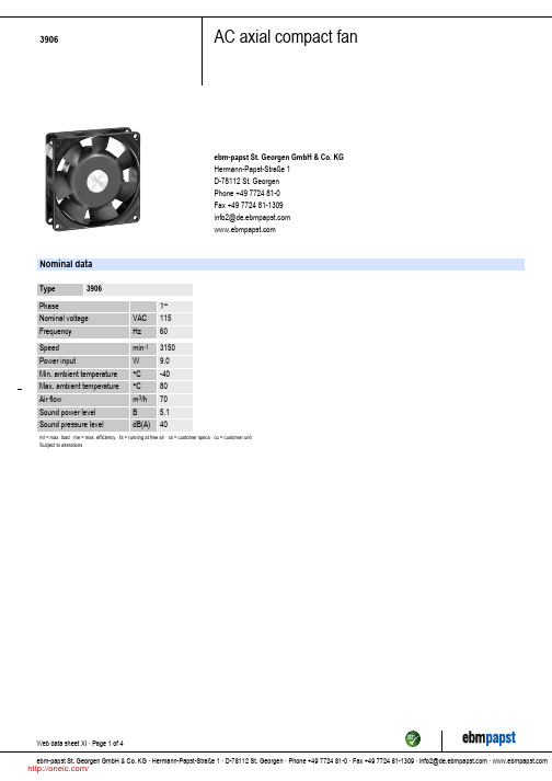
Mass Dimensions Material of impeller Housing material Direction of air flow Direction of rotation Bearing Lifetime L10 at 40 °C Lifetime L10 at maximum temperature Connection line Motor protection Approval
3906
AC axial compact fan
ebm-papst St. Georgen GmbH & Co. KG Hermann-Papst-Straße 1 D-78112 St. Georgen Phone +49 7724 81-0 Fax +49 7724 81-1309 info2@
Web data sheet XI · Page 2 of 4 ebm-papst St. Georgen GmbH & Co. KG · Hermann-Papst-Straße 1 · D-78112 St. Georgen · Phone +49 7724 81-0 · Fax +49 7724 81-1309 · info2@ ·
/
3906
AC axial compact fan
Charts: Air flow
(in H ² O) 0,05 0,10 0,15 0,20
∆ pf ä
60 50 40 30 20 10
0
10
20
30
CFM
Vä
•
10
20
30
40
50
60
m³/h
雷泰红外说明书
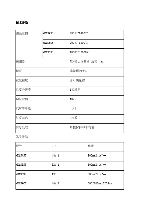
技术参数光学参数95%能量时,CF=近焦,SF=标准焦距最小焦距时的最小光点尺寸最小的光点尺寸直径=最小焦距/最小的D:S 一般参数电气参数仪器特点Marathon FA红外测温仪技术参数:1、温度测量范围: 250℃到 3000℃482°F to 5432°F2、光学分辨率最高可达 100:13、特别适用于现场安装空间狭小的安装条件4、精度高,测量值的± %5、更快速响应时间 10 毫秒,可选到10秒6、提供模拟量和数字量输出技术参数Marathon FA 红外测温仪介绍雷泰马拉松 FA 系列红外测温仪使用光纤技术可克服测量过程中各种极端的环境条件;FA 系列红外测温仪由电子盒和光纤探头、光缆组成,探测器和信号处理部分集成在一电子盒中,此电子盒可远距离放置,光纤探头和光缆可安装在强电磁场中的环境中,并且可耐的最高环温达200℃;雷泰马拉松FA 系列光纤测温仪的测温范围为250℃到3000℃482°F to 5432°F ,FA 光纤探头由耐用光缆将光学探头连接到电路盒上,电路盒包括:探测器、电子线路、内置用户接口、LED 显示及连接电缆的接线端子;FA1 和FA2 系列尤其适用于目标不能接近的、恶劣的工业环境,安装空间狭小的现场测温应用;雷泰 FA 系列单色光纤式测温仪的固定焦距的光学探头包括一个小的不锈钢圆柱形外壳和透镜,其可承受的环境温度高达200℃ ,并且符合NEMA-4的标准;雷泰 FA 系列的光纤探头可装一空气吹扫器以防止透镜被污染,光缆由金属套保护,并由VITON 保护套所密封,以防止水和油的流入,这种装配可使光缆以很小的半径弯曲以便其方便地穿过狭小的空间;雷泰 FA 系列单色光纤式测温仪还提供可在PC 上使用的WINDOWS下的马拉松软件,以实现远程进行参数设置、数据读取、数据的图形显示及RS485的多点网络配置;雷泰 FA 系列单色光纤式测温仪主要应用于以下行业:1、冶金及金属加工、热处理2、玻璃加工3、半导体加工等仪器特点Marathon FR红外测温仪技术参数:1、测温范围: 500°C 到2500°C 932°Fto 4532°F2、光学分辨率最高可达 60:13、使用光纤技术克服测量过程中的各种极端环境条件4、独特的"脏镜头"报警功能5、光缆可在现场更换,无需用黑体标定;马拉松FR1光纤双色测温仪测温范围为500~2500°C;这种测温仪可测量处于十分恶劣的工业环境中的目标,包括难以接近的,处于高温的以及靠近强磁场的目标;小巧焦距可选的光学头,由柔软可变形的光纤将其连接到安装在远处的电子盒上;Marathon FR红外测温仪特点:1、光缆可现场更换2、光缆组装系统可承受200°C 392°F高温,密封等级NEMA-43、粗糙的光缆可防水或油4、小于38mm 英寸的光缆弯曲半径5、高光学分辨率>60:1可测小目标6、单色或双色工作方式可选独有性能7、可聚焦的光学头8、快速响应时间可达10毫秒9、双向RS-485通讯可组成多头网络10、一个多点网络支达持多32个马拉松传感头11、同时模拟和数字输出并带用户报警设定12、独有的不洁窗口报警功能13、马拉松软件可遥控设置和监测14、现场标定和传感头诊断软件技术参数测量参数光学参数90%能量时,CF=近焦,SF=标准焦距可选激光瞄准电气参数产品详情雷泰MM在线式红外测温仪1、高光学分辨率,最高可达70:12、实时背景环境温度补偿、3、简单易用的操作界面4、光学和激光或视频瞄准方式5、坚固的不锈钢外壳6、模拟量和数字同步输出7、现场标定软件8、Windows操作系统下的datatemp多探头操作软件可以显示和分析测量到的数据9、传感头可以很容易的设置为标准单头运行模式,所有的MARATHOR MM系列探头又具有易于对准目标的光学瞄准和激光瞄准方式,MARATHON MM 还具有可选的视频瞄准方式;MARATHON系列测温仪包括双向485串口通讯能在工厂现场的单个探头或多探头测量网络与中控室的计算机之间进行通讯,这使得能对探头进行远程设置,监视,标定与维护,特别适合将探头安装在不易接近目标的位置;技术参数① 2ML型精度为±读数的%+2℃下②精度在环温23℃±5℃73°F± 9°F③在聚焦点处的光学系数电气性能概述环境参数概述更宽的测温范围:1、-40°C 到3000°C-40°F到5432°F2、光学分辨率最高可达 300:13、提供精确可变焦镜头4、可选择彩色视频瞄准模式5、配备光学瞄准和激光瞄准模式6、坚固的不锈钢外壳7、简单易用的操作界面8、实时视频监控和记录功能9、集单镜头反光式取景器TTL和视频或激光瞄准等多种观察方式于一身新型 Marathon MM 系列平台,温度测量范围为 -40℃ ~ 3000℃-40℉ ~ 5432℉,由 6 种红外线IR温度传感器组成,每一种传感器都可以测量一定范围的波长,并分别可以测量低温-40℃~800℃/-40℉~1472℉、中温250℃~1100℃/482℉~2012℉,或者高温300℃~3000℃/572℉~3273℉等温度范围的物体; 所有传感器均采用相同的安装硬件和雷泰RaytekDataTemp Multidrop 软件,安装、组态和数据采集方便、准确,用途广泛:1、钢铁和金属加工锻造和热处理2、新MM3M特别适用于低发射率的物体如铜、铝的金属加工3、玻璃热弯、成型、回火、退火,以及密封4、纸加工行业油墨干燥/固化和成型5、塑料加工和热力塑型;以及半导体加工等6、为满足多种行业的需求并扩大产品的应用范围,雷泰提供有六种 MM 传感器:型号温度范围光谱响应响应时间95% 响应LT-40°C - 800°C-40°F - 1472°F8 - 14 μm120 ms G5L250°C - 1650°C482°F - 3002°F5 μm60 ms450°C - 2250°CG5H5 μm60 ms232°F - 1322°F250°C - 1100°Cμm120 ms MT482°F - 2012°F100°C - 600°Cμm 2 ms 3ML212°F - 1112°F300°C - 1100°C2MLμm 2 ms572°F - 2012°F350°C - 2250°Cμm 2 ms 2MH852°F - 4082°F450°C - 1740°C1ML1 μm2 ms842°F - 2732°F650°C - 3000°C1 μm2 ms1MH1202°F - 5432°F特点:1、IP65 密封标准,可以防止安装、设置和使用过程中的污染和损伤2、标准模拟量、数字量和分布式继电器输出,可以同时传输数据、报警触发和控制信号3、内置 RS485 接口,可以以多分支multi-drop连接方式连接多达 32 个传感器4、使用雷泰软件,通过一台 PC,即可以进行远程监控、传感器控制,以及数据采集5、实时视频监控和记录功能6、更宽的温度测量范围: -40 ~ 3000℃/-40 ~ 5432℉7、集单镜头反光式取景器TTL和视频或激光瞄准等多种观察方式于一身8、高达 300:1 的高分辨率光学系统9、不锈钢外壳10、操作界面简单易用产品详情仪器特点XR系列为工业生产过程的工业控制提供持续的温度监测,秉承雷泰产品坚固、耐用的风格,其一体化的产品设计将可以帮助你在更多的应用环境下进行温度测量;雷泰XR系列特别适用较小目标或是使用较长瞄准管的温度测量,此外,直观的内置用户操作界面大大减少了产品设置时间,并且增加了强大的现场问题处理能力;雷泰XR系列使用最通用的安装配件和软件,极大降低了设备安装和调整的成本,可被安装在任何已经存在或运行的系统中,为生产过程提供持续的温度监测,从而精确控制温度变化,帮助客户降低能源损耗;性能亮点:1、提供多种温度的测量范围2、内置电子操作面板3、提供数字和模拟量输出4、高光学分辨率5、符合NEMA-4密封标准技术参数可选附件产品描述:雷泰 XR 系列为工业生产过程的工艺控制提供持续的温度监测;XR 系列秉承雷泰产品坚固、耐用的风格,符合 NEMA-4 密封标准,其一体化的产品设计将可以帮助您在更多的应用环境下进行温度测量;雷泰XR 系列提供多种温度的测量范围,高光学分辨率, RS485数字输出,简单易于使用的电子操作面板可以帮助您解决工业生产中所遇到的测温难点;具备激光瞄准方式可选和高光学分辨率的雷泰 XR 系列特别适用于较小目标或是使用较长的瞄准管的温度测量;此外,直观的用户操作界面大大减少了产品设置时间并且增加了强大的问题处理能力;雷泰XR 系列使用最通用的安装配件和软件,极大降低了设备安装和调整的成本;此外,雷泰XR 系列可提供模拟量输出,这种方式使 XR 系列可被安装在任何已经存在或运行的系统中;雷泰 XR 系列为生产过程提供持续的温度监测,从而精确控制温度变化,帮助客户降低能源消耗;响应波长光学分辨率型号温度范围-40°C到600°CLT 低温型8到14 μm33:1-40°F to 1112°F-40°C到600°CLTHSF 低温型8到14 μm50:1-40°F to 1112°F250°C到1200°CMT 中温型μm30:1482°F to 2190°F250°C到1650°Cμm33:1 G5 玻璃专用型482°F to 3002°F10°C到360 °CP7 塑料专用型μm30:150°F to 680 °F产品详情仪器特点TX/SX系列集成式传感头提供精确的温度测量从适于多变的过程控制应用,通过双通道的数字通道;1、简单的双线安装2、坚实耐用的传感头符合IP65NEMA4标准3、款温度范围:-18~2000度4、在单一多头网络上安装可多达15个传感头5、Windows下软件以远程探头设置和监测6、通过透镜或激光瞄准7、4-20mA和数字同时输出8、信号处理9、焦距多种可选10、玻璃和塑料的特殊型号TX系列红外测温仪集高性能的非接触温度测量和标准二线技术于一体;用户可选择基本型或智能型;LT:印刷、造纸、层压、干燥/加工、食品、纺织、制药MT:冶金、窑炉、平板玻璃、耐火材料、加热炉HT:感应加热、加热炉、金属冶炼G5:玻璃表面测量如回火、退火、热成型、封接、弯曲等P7:氟塑料、特氟龙、丙烯酸、尼龙、聚乙烯、聚氯乙烯薄膜和复合材料的生产技术参数可选附件1、瞄准镜2、空气吹扫器3、NIST/DKD标定证书4、空气/冷却套可选5、直角反射镜6、热保护套7、℃/℉适用于基本型8、本证安全型表示订货时必须说明Thermalert TX红外线温度传感头现有两种配置可选:1. TX基本型传感头单探头使用时提供优良性能.2. TX智能型传感头, 具有远程寻址功能,可以方便安装在多点网络上如监测玻璃和塑料的工艺生产线;TX系列智能型传感头在简单的二线回路上采用HART通讯协议进行通讯;输出信号同时包括工业标准的4-20mA和数字信号;Thermalert TX一般性能指标:1、简单的二线安装2、温度范围宽,从-18° 到2000°C -0° to 3600°F3、对于TX智能型传感头可同时有4-20 mA和数字输出4、耐用的传感头符合NEMA-4 IP 65标准5、先进的信号处理6、点对点或者多点安装最多安装15个传感头7、Windows操作系统软件,可进行远程设置和显示8、多种焦距范围可选9、有玻璃和塑料的专用型号10、DataTemp TX软件专门为PC机上的运行而编写的DataTemp TX软件大大简化了Thermalert TX的操作;DataTemp TX软件允许你设定温度和输出范围、发射率、报警点,而且在实时图形显示上,可以从一个点或者多个传感头监测温度数据;你可以记录和保存这些数据并导入总分析表和数据库程序;程序还有下拉菜单、友好用户界面,外加在线提示信息和帮助;产品详情仪器特点雷泰在线红外测温仪中国一级代理提供Raytek MI3 红外测温仪报价咨询,欢迎选购;Raytek MI3是一款功能强大的分体式红外线温度测量系统,具有微型传感头和独立的通讯电子盒;该传感器体积小巧,几乎可安装于任何地方,其性能却远远优于大型系统;Raytek MI3是一款功能强大的分体式红外线温度测量系统,具有微型传感头和独立的通讯电子盒;该传感器体积小巧,几乎可安装于任何地方,其性能却远远优于大型系统;同时具有坚固的金属铸造电子盒外壳,创新的DIN安装的多通道连接盒或低廉的OEM配置供选择;MI3提供其它昂贵的传感器所不具备的大量高级信号处理功能;为OEM设计的MI3可以直接和主机控制器进行数字通信而无需另外的通信盒;创新的8个传感头设计,可独立寻址,降低红外测温成本,简化测温设置和方案实施的故障率,并且测量点成本更为低廉;MI3 也可实现在封装测试中实现USB和RS485数字通信;技术参数应用:工业OEM;印刷,纸业,纺织,锻造, 干燥和固化;沥青和建筑材料;制塑,热成形,制模,焊接,密封;固化烘箱和工业干燥箱;食品加工,制药业;设备检测与保养;导线和开关检测 ;电气技电气技术指标MI3COMM电气技术指标MI3MCOMM感应头技术指标产品详情仪器特点雷泰GP红外测温仪产品特点:1、温度范围是从-18 到538°C 0 到1000°F2、最新GPS激光瞄准头3、耐用的1/8 DIN 数字显示表,4位数字大窗口4、监视器和传感器功能设置位于前面板5、具有许多只有在大系统上才有的数据处理能力6、发射率和环温参数可调7、全球统一的110-220 V交流电源8、用户设置的4-20 mA或者热电偶输出J, K, E, N, R, S, T9、可调的双设置点和死区报警输出10、根据不同应用,可接多种探头11、标准或近焦距可选12、冷却和空气吹扫附件13现场可更换探头技术参数测量参数电参数探头参数产品详情仪器特点raytek 在线红外测温仪中国一级代理提供raytek cm在线红外测温仪报价咨询,欢迎选购;雷泰新一代CM 高性能迷你型红外测温仪, 专为工业设备用户的多种应用需求选择. CM红外测温仪温度范围广、精度高、体积小、多种输出模式、性价比高,是系统集成商、设备配套Raytek CM红外线测温仪特点:OEM用户的最佳选择1、测温范围: -20 ~ 500 ℃ -4 to 932°F2、光学分辨率: 13:13、响应时间:150 毫秒4、机身为不锈刚外壳,密封等级: NEMA-4X, IP655、输出:0-5 V 输出, J 型或K型输出, RS232, 报警输出6、LED 探头故障自检功能7、RS232 数字通讯,可远程控制、设置探头参数8、信号处理可调9、WINDOWS 下DataTemp 多探头专用温度监控软件10、多种附件可选:空气吹扫器及镜头保护附件技术参数性能描述:雷泰新一代CM 高性能迷你型红外测温仪, 专为工业设备用户的多种应用需求选择. CM红外测温仪温度范围广、精度高、体积小、多种输出模式、性价比高,是系统集成商、设备配套商的最佳选择;C M探头自带J型或K型热偶输出,可以很容易地替代设备中已使用的传统热偶, 此外,CM还提供0-5伏的输出方式;CM 新一代迷你型红外测温仪采用不锈钢机身,仪器的密封等级达到“IP 65 NEMA-4 ”,使得CM探头在即使没有水冷套的情况下,依然可以在最高70°C 160°F 的环境温度下正常工作;CM新一代红外测温仪是目前市场上同类产品中,功能最强大的一款小尺寸产品; CM 的RS232 数字通讯接口、专用的WINDOWS下操作软件为操作者远程设置参数、探头远程监控可同时监控多个探头提供极大的方便; 此外,CM 还内置LED 故障指示灯,当探头在非常状态下时,该指示灯会提示不同灯光信号提示,用户可根据操作手册的上面的灯光指示对应的状态来实时了解仪器的工作状态;电参数物理性能产品详情仪器特点雷泰MID系列红外测温仪由很小的传感头和电路盒组成,电路盒内置LCD温度显示和设置按键,具有多种信号处理功能和输出方式,还具有环温补偿、报警、传感头可换等特点;技术参数美国RAYTEK MID系列在线式产品介绍:雷泰MID系列红外测温仪由很小的传感头和电路盒组成,电路盒内置LCD温度显示和设置按键,具有多种信号处理功能和输出方式,还具有环温补偿、报警、传感头可换等特点;主要应用:OEM、塑料、造纸、印刷、铁路、烟草、食品加工及包装机械等;美国雷泰RAYTEK MID系列在线式红外测温仪主要特性1、输出:4~20mA,0~20mA,0~5V 三种标准信号 J 或 K 型热偶,10mV/℃传感头环温信号,2、RS232/RS485可选3、光谱响应:LT/G5/MTP:8~14μm/5μm/~4μm4、响应时间:150ms5、重复性:±1% 或±1 ℃,取最大值6、发射率可调:~,步长7、尺寸:传感头:28 x 14mm;8、电路盒:80 x 60 x 25mm9、重量:传感头带1m 电缆50g;电路盒270g10、美国雷泰RAYTEK MID系列在线式红外测温仪技术参数:。
3006热工仪表校验仪

CST3006热工仪表校验仪主要用途: 热工仪表校验仪主要参数: 全数字,智能化,高可靠性CST3006热工仪表校验仪产品介绍:CST3006热工仪表校验仪概述:CST3006热工仪表校验仪是专门为校验热工仪表和DCS系统而设计的,全数字化操作,使用极其方便。
CST3006热工仪表校验仪可输出电流、电压(10V、100mV)、电阻、频率信号,也可以模拟热电偶(S、R、B、K、N、E、J、T)输出设定温度对应的电压信号,也可以模拟热电阻(Pt100、Pt10、Cu100、Cu50)输出设定温度对应的电阻信号。
CST3006热工仪表校验仪可测量电流、电压(±30V、±150mV)、电阻、频率以及通断信号。
还可以配接热电偶(S、R、B、K、N、E、J、T)或热电阻(Pt100、Pt10、Cu100、Cu50)作为高精度温度测量使用。
CST3006热工仪表校验仪特点:◆输出、测量与DC24V电源输出全部隔离,相互独立,互不影响;CST3006热工仪表校验仪主要用途: 热工仪表校验仪主要参数: 全数字,智能化,高可靠性CST3006热工仪表校验仪产品介绍:CST3006热工仪表校验仪概述:CST3006热工仪表校验仪是专门为校验热工仪表和DCS系统而设计的,全数字化操作,使用极其方便。
CST3006热工仪表校验仪可输出电流、电压(10V、100mV)、电阻、频率信号,也可以模拟热电偶(S、R、B、K、N、E、J、T)输出设定温度对应的电压信号,也可以模拟热电阻(Pt100、Pt10、Cu100、Cu50)输出设定温度对应的电阻信号。
CST3006热工仪表校验仪可测量电流、电压(±30V、±150mV)、电阻、频率以及通断信号。
还可以配接热电偶(S、R、B、K、N、E、J、T)或热电阻(Pt100、Pt10、Cu100、Cu50)作为高精度温度测量使用。
CST3006热工仪表校验仪特点:◆输出、测量与DC24V电源输出全部隔离,相互独立,互不影响;尺寸:245mm×295mm×50mm;重量:2.5kg。
3006p电位器参数

3006p电位器参数## Potentiometer 3006P.English Answer:The 3006P potentiometer is a high-performance, precision potentiometer that offers excellent linearity and low noise. It is widely used in various applications, including audio, industrial, and medical equipment.Key features of the 3006P potentiometer include:Resistive element: Conductive plastic.Resistance range: 10 ohms to 10 megohms.Linearity: Up to 0.1%。
Power rating: 0.15 watts.Operating temperature range: -25°C to +70°C. Dimensions: 9mm (diameter) x 12mm (length)。
Advantages of using the 3006P potentiometer: Excellent linearity.Low noise.High stability.Long life.Cost-effective.Applications of the 3006P potentiometer:Audio equipment.Industrial machinery.Medical devices.Aerospace and defense.Precision instruments.## 电位器 3006P.中文回答:3006P电位器是一款高性能精密电位器,具有出色的线性度和低噪音。
RadiPower 产品手册说明书

Models: RPR3006W RadiPower ®Product ManualRF Power MetersPage 2 of 19RadiPower® product manualThis product manual pertains to the RadiPower®.Models: RPR3006W - RPR3008W - By Raditeq 16/08/21All trademarks used in this manual are the property of their respective ownersSupplier InformationRaditeq B.V.Vijzelmolenlaan 33447 GX, WoerdenThe NetherlandsTel.: +31 (0)348 200 100Internet: Email: *****************Read this manual carefully before operating the product and make sure all the safety instructions are strictly followed.For your convenience, a Quick Start Guide has been added to this product. This Quick Start Guide contains the basic start-up steps and the safety warnings.Please keep the Quick Start Guide (and this regular manual) close at hand when you operate your new Raditeq product(s).Please contact your local reseller if you have any questions.Table of contentsWARNINGS & PRECAUTIONS 4 Introduction 5 The RadiPower® Series 6 Product characteristics 6 Functional description 7 The RadiPower® 3000 Series 8 Model RPR3006W 8 RadiPower® Installation 9 Stand-alone Configuration 9 Software Configuration 10 How to configure the RadiPower® in RadiMation® 10 How to connect the RadiPower® to the RadiCentre® 11 How to check whether the RadiPower® is properly connected to RadiMation® 11 Adding coupler values in RadiMation®12 Theory of operation in burst mode 13 Prefix & Communication example: 13 Remarks about the general commands 14 Stand-alone command set 14 Burst Mode 15 Specifications RPR3006W16 Warranty Conditions18Page 3 of 19WARNINGS & PRECAUTIONSRead the contents of this product manual carefully and become familiar with the safety markings, the product instructions and the handling of the system. Please refer to the applicable product manual(s) for further information regarding the operation and control of the product(s).Only Raditeq qualified maintenance personnel is allowed to perform maintenance and/or repair service on the equipment.This product® contains materials that can be recycled and reused to minimize material waste. At the ‘end-of-life’, specialized companies can dismantle the discarded system to collect the reusable and recyclable materials. If your product is at its ‘end-of-life’, please return it to your local reseller or to Raditeq for recycling.For cleaning, use a clean, dry cloth (or a damp cloth where needed) and wipe the surface of equipment.This product contains no hazardous substances as described in the RoHS Directive (2015/863/EU).This product contains embedded software, which is field upgradeable.For more information contact your local reseller or go to Page 4 of 19IntroductionThis manual contains information about the RadiPower® RPR3006W RF power meters.An accurate power meter is indispensable to perform reliable EMC measurements. The RadiPower® is a RF power meter especially designed for power measurements during EMC tests. The RadiPower® is an affordable, accurate and fast power meter. It provides accurate measurements over a wide frequency range, which enables effective measurements in accordance with the latest EMC standards.Please read this manual carefully and make sure to pay special attention to the chapters regarding your new product(s).RadiCentre® SystemThe RadiCentre® is a modular EMC/RF test system that serves as the interface between user and computer for all the RadiCentre® plug-in cards and modules.RadiMation® SoftwareRadiMation ® is the EMC software package from Raditeq used for remote controland automated testing of the RadiCentre® plug-in cards and modules and is sold separately. RadiField® Electric Field GeneratorThe patented RadiField® Triple A is no less than a revolution in EMC immunity testing.A complete paradigm shift involves a combination of high-level integration anda field combining technique, making several discrete components like combiner,coupler, power meters and cabling superfluous. This product is sold separately.RadiMationShielded USB cable Model: USB A male to USB mini B5 male.To connect the RF power sensor to a USB connector.The RadiPower® 3000 SeriesMMCX Trigger cable For measurements on multiple ports.RadiPower® RF power sensor Model: RPR3006W.Supporting documentation is supplied on a USB stick containing:•The (digital) User Manual and Quick Start Guide.•The installation of RadiMation® Free software and drivers.• Optional - The calibration certificate for the power meter.The RadiPower® RF power sensor is optimized for EMC measurements, where a high dynamic range, together with fast measurements, are required even at low power levels. Where most power sensors require long measurement times at low RF levels, the RadiPower® RF power sensor is able to perform accurate power measurements, with a high measurement speed, at power levels close to the noise floor, without the need for zero adjustment!Fast - EMC immunity measurements are time consuming. This is mainly dependent on the number of frequency points, the dwell time and the speed of the power meter. As the first two parameters are generally prescribed by standards, the only one that can be optimized is the speed of the power meter. The unprecedented detector technology of Raditeq’s power meters makes extremely fast and accurate power measurements a reality, even at low power levels.Accurate - Accuracy is another concern in addition to speed, when performing EMC measurements. The RadiPower® allows for high precision EMC measurements with a large dynamic range. Because the RadiPower® has a high accuracy over the complete band, it is suitable for measurements in accordance to automotive, military, telecom and EMC basic standards such as the IEC61000-4-3/6 standards.Simultaneous power measurements on multiple ports - The RadiPower®RPR3006W has two trigger ports (MMCX) which can be used to synchronizemultiple power meters. These power meters connected through a daisy chaintrigger each other to make time synchronized measurements. Due to this functionmeasurements of WLAN and/or MIMO devices according to the EN 300 328 andEN 301 893 standards.All necessary parameters can be set and calculated by RadiMation® Free (or ahigher version) making the setup and measurements effortless.Low measurement uncertainties - Impedance mismatches contribute to themeasurement uncertainty. The RadiPower® has a very low Standing Wave Ratio(SWR) and as a result, measurement uncertainties are low compared to othercontributions in the EMC measurement setups.Robust housingThe RadiPower® RF power sensor is mounted in a rugged metal housing to ensure a long life and excellent RF shielding. The power sensor is equipped with an N-type precision RF input connector and a mini USB-B connector for communication with a computer.Easy to use - With the USB interface the RadiPower® is easy to use. In addition, the RadiPower® can be controlled by both the RadiMation® integral EMC measurement software and any other EMC measurement packages, because all the software commands needed to control the unit are available. For ‘stand-alone use’ of the RadiPower®, RadiMation® Free measurement software is delivered with the power meters. The RadiPower® 3000 SeriesProduct characteristicsFunctional descriptionThe RadiPower® uses a high speed power detector to measure the RF signal, independent of the crest factor of the input signal waveform. The detected signal is sampled, at high speed, by a high speed ADC and the samples are processed by a powerful DSP. The sophisticated software enables unique functions, such as envelope tracing and burst logging. The table below shows which models support the different measurement modes.0 : CW1 : Peak √√2 : Envelope tracing√3 : Burst√CW modeThe RadiPower® performs RMS power measurements of CW-signals. In RMS mode the RadiPower® samples the signal at high speed. The RMS value of the power is calculated over the number of samples defined by the filter setting and can be read by a simple command. Due to the high sampling speed the number of readings is high, even at large filter settings. This mode is supported for all the RadiPower® models.Peak modePeak mode keeps track of the maximum power that is measured during a specific time interval. In PEAK mode, the “power?”-command will return the highest value that was measured since the last “power?”-command. After each cycle of the command the previous peak value is cleared,Burst modeIn burst mode, the RadiPower can measure a burst of RF power. It is even possible to measure a burst on multiple powermeters at the sime time (using the MMCX trigger ports). The power readings of each powermeter can be combined to a total power by RadiMation according to the EN 300 328 and EN 301 893 standards..In this mode the sample speed can be set to either 1 MS/s or 5 MS/s. The RadiPower can store a total of 100.000 bursts and is independent of the observation time. The stored data of a single burst consists of the RMS power and the start/stop-time of the burst. The start and stop time are defined by how long the power was higher than the threshold value. The threshold value can be set in RadiMation.The RMS power of a burst is calculated according to the following formula:Where m is the number of RMS power samples within the start and stop time. When measuring on a MIMO device with more than one port. It is possible to use multiple power meters. The burst values of each power meter can be combined to a single RF power using RadiMaiton. This can also be done manual by using the following formula:i is the number of power metersIt is also possible to add corrections for the coupler, beamforming gain (Y) and the assembly gain (G) of the DUT. RadiMation can compensate for these values.Connect the RadiPower® sensor to a Windows computer with a USB port for ‘stand-alone’ use. Use the supplied USB cable to connect the sensor to your computer. Windows will prompt that new hardware has been found. The USB-driver for the RadiPower® is Windows certified and will be loaded automatically from the Windows update. If the drivers are not loaded automatically, these can be installed manually from the supplied USB-key. Follow the normal instructions from Windows to install the drivers manually.Once the drivers are loaded successfully, the RadiPower® will be shown in the device list.RadiPower® InstallationStand-alone Configuration Connect the RadiPower® sensor to a Windows computer with a USB 2.0 compatible port. Use the supplied USB cable to connect the RadiPower® sensor. The hardware installation for the RadiPower® sensor is now complete.Software ConfigurationIn order to control the RadiPower® from a computer, the RadiMation® EMC software package can be used. RadiMation® from Raditeq is sold separately. A free version of RadiMation® is available on: https://www. /automated-emc-software/radimation-free/.If the RadiPower® is operated manually, this chapter can be skipped.The RadiPower® device driver is part of the Power Meter Device Driver familyHow to configure the RadiPower® in RadiMation®1. Start the latest version of RadiMation®; https:///radimation-download/2. Select the button ‘Device’ at the top menu bar, followed by clicking ‘Configure’;3. In the configuration screen select ‘Device Drivers’ and Select ‘Power meter’ or any of the otherdrivers as driver type;4. Click the ‘Add’ button to open the selection of available drivers in RadiMation®;5. Enter ‘RadiPower’ in the search bar which will show all available RadiPower® drivers;6. Select the correct driver, double click it (Optional, rename it) and press ‘OK’.2354How to check whether the RadiPower® is properly connected to RadiMation®1. Select ‘Devices’ in the top menu bar2. Open ‘Device Drivers’ and select device driver type: ‘Power Meter’3. Double click the recently configured RadiPower® or click ‘Edit’.4. Finally select the ‘Check’ button on the right side of the opened screen.5. When correctly configured, RadiMation® will notify you that the device is correctly installed.23Adding coupler values in RadiMation®In a MIMO test setup, power measurements are often performed using a coupler on the antenna port. Coupling factors can be compensated by RadiMation® using a correction file. If no couplers or additional attenuators are used in the setup, there is no need to create and apply these correction files.To create a correction file, select “File” – “New” – “Correction” from the menu bar.Press “Colums/units” to create to columns for Frequency and Attenuation.To create a constant correction versus frequency:• Press “Add Row” and enter the lowest frequency with the corresponding attenuation.• Press “Add Row” again and enter the highest frequency with the corresponding attenuation.If calibration data of the coupler is available, this data can be used to create an accurate correction for the coupler.After all data has been entered, select “File” – “Save Correction As” to save the data.Next, the correction data of the coupler has to be added to the correct power meter. Select “Configuration” and “Configuration” again. In the Configuration window select the “Device drivers” tab and select the power meter for which the correction has to be added. Press “Edit”.Press the “file open”- button in de Correction Files area to select the correction file. Perform this procedure for each power meter for which a coupler correction has to be added. RadiMation® will now automatically calculate the power values, including the coupler values.Stand-alone command setCommunication with the RadiPower® sensor is possible using a virtual COM-port (VCP)For more information see chapter ‘stand alone configuration’.NOTE: All commands can be found in the RadiCentre® Manual under the programming manual.Specifications RPR3006W & RPR3008W1. In burst mode only 1 and 5 MS/s can be set and used.• All specifications are measured after 10 minutes warm-up time and 0dBm unless specified otherwise.• T ypical specifications indicate that the measured values a re met on at least 80% of the points.• Three years warranty will be granted only after you register the product at . Without registration, a 1 year warranty period applies.For more information about the current and new Raditeq products at:T:+31348200100M:*****************W: Warranty ConditionsRaditeq B.V. offers a standard warranty term of three (3) years on their products, calculated from the shipping date, under the condition that the product is registered on . For registration of the product, the customer should provide the product model, serial number and the responsible reseller (if applicable). If the product is not registered, a limited warranty term of one (1) year will be applicable.Return Material Authorization (RMA) & Warranty repairIf a defect occurs to our product within the warranty term, a Return Material Authorization (RMA) ‘Warranty Repair’ request can be issued using the RMA link at /support. Upon receipt of the request, an RMA number will be provided. Please do not send the product without this RMA number! The defective product should be shipped to our service department at the following address:Raditeq B.V. – Service DepartmentVijzelmolenlaan 33447GX WOERDENThe NetherlandsThere will be no charge for repair services (materials or labour) within the (extended) warranty term.These warranty terms are not applicable to:• Normal wear and tear• Fibre optic cables• Products that have been improperly used• Products that have been used outside their specified range• Products that have been improperly installed and/or maintained• Products that have been modified without approval of Raditeq• Calibration and/or re-calibration of the productRepair services on products that are not covered by the Raditeq warranty will be charged to the customer.Repairs outside warrantyIf a defect is not covered under warranty, an RMA fixed-repair can be ordered on the RMA link: /support If a re-calibration is needed after repair, this calibration should be ordered separately. The calibration will be performed at the ISO17025 accredited calibration laboratories of DARE!! Calibrations, based on the applicable service code / prices. Warranty after repairFor repairs outside the original warranty period, a limited warranty of six months is applicable on the performed repair. Shipping conditions are the same as with repairs that are covered within the original warranty period.ShippingThe customer will need to arrange shipping and cover for the costs (like e.g. transportation costs, duties, taxes) for sending the defect product the service department of Raditeq in The Netherlands. Raditeq will arrange the courier and cover for the costs for the return shipment after repair.EU Declaration of Conformity WeRaditeq B.V.ofVijzelmolenlaan 3NL-3447GX WoerdenThe Netherlandsdeclare under our sole responsibility that theProduct: RadiPower® Seriesmodels: RPR3006Ware in accordance with the European directives:EMC Directive 2014/30/EULow Voltage Directive 2015/35/EURoHS Directive: 2015/863/EUper the provisions of the applicable requirements of the following harmonized standards: Emission: EN 61326-1:2013, Class A1Electrical equipment for measurement, control and laboratory use.Immunity:EN 61326-1:2013, Industrial level, performance criteria AElectrical equipment for measurement, control and laboratory use.Safety:EN 61010-1:2010, Safety requirements for electrical equipmentfor measurement, control, and laboratory useThe technical construction files are maintained at the adress specified above.Date of issue:16/08/21Place of issue:Woerden, The NetherlandsAuthorized by:P.W.J. DijkstraTitle of authority: DirectorRaditeq B.V. | Vijzelmolenlaan 3 | 3447GX Woerden | The Netherlands | T:+31 348 200 100。
A3P060中文资料

ProASIC3 Devices
ARM-Enabled ProASIC3 Devices
A3P030 A3P060 A3P125
A3P250 3
A3P400 3
M7A3P250 3, 4 M7A3P400 3 I/O Type
A3P600 M7A3P600
A3P1000 M7A3P1000
Single-Ended I/O Single-Ended I/O Single-Ended I/O Single-Ended I/O2 Differential I/O Pairs Single-Ended I/O2 Differential I/O Pairs Single-Ended I/O2 Differential I/O Pairs Single-Ended I/O2 Differential I/O Pairs
BTS3006C培训胶片

2023/5/19
BTS3006C培训胶片
前言
• 本课程介绍了M900/1800 BTS3006C的硬件 结构、硬件配置、单板功能以及操作维护 和系统的工作过程
BTS3006C培训胶片
Page 2
参考资料
• BTS3006C技术手册 • BTS3006C性能描述手册 • BTS3006C单板手册
DAFM DDPM DDCM DSCM DATM DPSM DSEM
模块英文全称 Main Control Module for DDRM BTS BTS3006C Module Backplane Double transceivers Digital and Radio frequency Module
MSC/VLR
BTS3006C
MAP
MS BTS3006C
MS: Mobile Station HLR: Home Location Register MSC: Mobile Switching Center VM: Voice Mailbox
BTS OMC
HLR/AUC/EIR
SMC/VM
BTS: Base Transceiver Station
FAN
SMA型母头 SMA型母头 SMA型母头 SMA型母头 防水型圆形插头
载波1主集接收口或载波1第一分集接收口。 载波1分集接收口或载波1第二分集接收口。 载波2主集接收口或载波1第三分集接收口。 载波2分集接收口或载波1第四分集接收口。 风扇供电和风扇控制。
BTS3006C培训胶片
Page 19
第1章 BTS3006C产品概述 第2章 BTS3006C硬件结构 第3章 BTS3006C典型配置
英斯特朗试验机3300系列产品手册

非洲,见 网站 奥地利 +49 6151 3917 444 比利时 +32 3 454 0304 芬兰 +44 1494 456815 法国 +33 1 39 30 66 30 德国 +49 6151 3917 444 爱尔兰 +44 1494 456815 意大利 +39 02 390 9101 卢森堡 +32 3 454 0304 中东,见 网站 荷兰 +32 3 454 0304 挪威 +44 1494 456815 西班牙和葡萄牙 +34 93 594 7560 瑞典 +44 1494 456815 瑞士 +0800 561 550 英国 +44 1494 456815
保持材料科学领先地位
• 可在现场或地区性培训中心提供培训课程 •利 用我们的应用工程实验室或定制工程解决方案组,获取材料试验方面的最新技术进展 •我 们一流的标定实验室保证所有的标定满足最新的 ASTM 或 ISO 技术指标
期待完善的售后服务和支持?
12
“使用英斯特朗, 有更多的产品通过 了我们的失效分析 试验。这意味着缩 短了试验所用的时 间,减少产品浪费 并可以及时交付我 们的客户。”
双立柱
3365 3366 3367 3369 5 10 30 50 500 1,000 3,000 5,000 1,125 2,250 6,750 11,250 1,000 500 500 500 40 20 20 20 1,200 600 600 500 48 24 24 20 1,122 1,122 1,122 1,122 44.2 44.2 44.2 44.2 1,193 1,193 1,193 1,193 47 47 47 47 420 420 420 420 16.5 16.5 16.5 16.5 1,582 1,582 1,582 1,582 62.3 62.3 62.3 62.3 756 756 756 756 29.8 29.8 29.8 29.8 707 707 707 707 27.8 27.8 27.8 27.8 110 110 121 141 242 242 266 312
ER 系列 EMI 测试接收机快速指南说明书
ER系列EMI测试接收机(ER300/ER2000/ER3600)快速指南一般性检查●请检查运输包装如运输包装已损坏,请保留被损坏的包装或防震材料,直到货物经过完全检查且仪器通过过电性和机械测试。
因运输造成仪器损坏,由发货方和承运方联系赔偿事宜。
●请检查整机若存在机械损坏或缺失,或者仪器未通过电性和机械测试,请您联系发货方。
●请检查随机附件请根据发货清单检查随机附件,如有损坏或缺失,请您联系发货方。
一般安全概要了解下列安全性预防措施,以避免受伤,并防止损坏本产品或与本产品连接的任何产品。
为避免可能造成的危险,请务必按照规定使用本产品。
请使用所在国家认可的本产品专用电源线请将产品可靠接地请查看并核对所有终端额定值请使用合适的过压保护请勿开盖操作请勿在潮湿环境下操作请勿在易燃易爆的环境下操作请保持产品表面的清洁和干燥请注意防静电保护请保护射频输入端口请勿使输入端过载请勿将异物插入风扇的排风口请注意搬运安全ER 系列接收机简介ER 系列EMI 接收机符合CISPR 16-1-1标准,集成了CISPR-AVG 、CISPR-RMS 、QPK 检波器,根据CISPR 、EN 、FCC 和MIL 等标准进行电磁干扰测量,适用于家电、照明、汽车电子、医疗等行业的EMI 测试。
结合ETR 上位机测量软件、丰富的测试选配件,可进行精确的自动化测试。
全系标配频谱分析模块和跟踪信号发生器,满足不同领域用户的测试需求。
前面板①②③④⑤⑥⑦⑧⑨⑩⑪⑫⑬⑭⑮图1 前面板视图编号说明编号说明① 电源键⑪ 下方向键 ② USB HOST 2.0接口 ⑫ 上方向键 ③ 射频输出 ⑬ 撤销键&LOCAL ④ 射频输入 ⑭ 退格键 ⑤ TFT-LCD ⑮ 数字键区 ⑥ 功能键区 ⑯ ⑦ 菜单键 ⑰ ⑧ 单位键区⑱⑨ 确认键⑲ ⑩ 脉冲旋钮⑳前面板功能键图2 前面板功能键设置接收、中心、起始和终止频率,弹出与频率相关的软菜单EMI 接收机模式下无效,频谱仪模式下激活频率扫宽,设置频谱分析仪为中心频率扫宽模式,弹出对扫宽进行设置的软菜单激活参考电平功能,设置参考电平、射频衰减器、刻度等参数 设置分辨率带宽和视频带宽相关参数 设置扫描模式、扫描时间等参数 设置触发选项设置扫频信号的迹线相应参数设置检波方式通过光标读取迹线上各点幅度、频率或扫描时间等。
Ariete NS3006 高压泵说明书
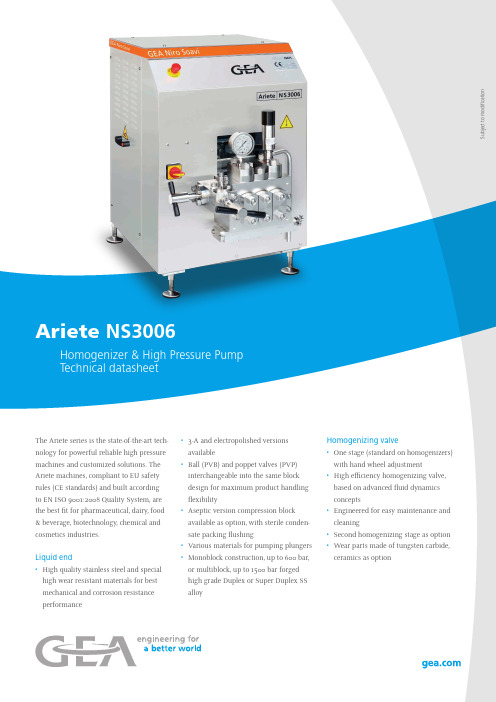
NS3006The Ariete series is the state-of-the-art tech-nology for powerful reliable high pressure machines and customized solutions. The Ariete machines, compliant to EU safety rules (CE standards) and built according to EN ISO 9001:2008 Quality System, are the best fit for pharmaceutical, dairy, food & beverage, biotechnology, chemical and cosmetics industries.Liquid end• High quality stainless steel and special high wear resistant materials for best mechanical and corrosion resistance performance • 3-A and electropolished versionsavailable• Ball (PVB) and poppet valves (PVP)interchangeable into the same blockdesign for maximum product handlingflexibility• Aseptic version compression blockavailable as option, with sterile conden-sate packing flushing• Various materials for pumping plungers• Monoblock construction, up to 600 bar,or multiblock, up to 1500 bar forgedhigh grade Duplex or Super Duplex SSalloyHomogenizing valve• One stage (standard on homogenizers)with hand wheel adjustment• High efficiency homogenizing valve,based on advanced fluid dynamicsconcepts• Engineered for easy maintenance andcleaning• Second homogenizing stage as option• Wear parts made of tungsten carbide,ceramics as optionSubjecttomodificationAriete NS3006Homogenizer & High Pressure PumpPower end• Cast iron power frame• Heavy duty and reliable power frame housing the transmission elements • AC motor drive• Splash type lubrication system, forced as option • “V” belts direct drive• Polished SS machine casing on stainless steel frame Casing• Polished stainless steel with removable panels for easy access and maintenance• Stainless steel AISI 304 base frame on adjustable legs Plungers• Chrome coated stainless steel • Tungsten carbide coated stainless steel • Solid ceramic• HCR Chromium Carbide coated stainless steel Tools and spare parts• Ordinary maintenance tools and one set of emergency spare parts supplied with the machine• O&M manual and spare part list on CD-ROM Pump valves• High wear resistant Stellite™ alloy removable seats • Ball type (PVB) or poppet type (PVP) in solid Stellite™• Ceramic or tungsten carbide materials available as option Pressure measurement & control • Sanitary design analog high pressure gauge• Pressure transmitters and transducers available as option • Overpressure relief valve installed on compression block Product line connections• DIN 11851, Tri-Clamp™, GEA Tuchenhagen Varivent™• Others as option upon requestT h e i n f o r m a t i o n c o n t a i n e d i n t h i s b r o c h u r e m e r e l y s e r v e s a s a n o n -b i n d i n g d e s c r i p t i o n o f o u r p r o d u c t s a n d i s w i t h o u t g u a r a n t e e . B i n d i n g i n f o r m a t i o n , i n p a r t i c u l a r r e l a t i n g t o c a p a c i t y d a t a a n d s u i t a b i l i t y f o r s p e c i fi c a p p l i c a t i o n s , c a n o n l y b e p r o v i d e d w i t h i n t h e f r a m e w o r k o f c o n c r e t e i n q u i r i e s . S u b j e c t t o m o d i fi c a t i o n · R E V 04-2016Main options on request • High pressure pump version • 2nd stage homogenizing valve• Electric power board for fixed or variable capacity • Machine automation and remote controls • Aseptic execution• 3-A execution, FDA approved gasket and cGMP documentationDesign features Number of plungers 3Stroke40 – 50 mm Max. motor power 5.5 kW Net weight 500 kg Gross weight650 kg Lubricating and cooling water 60 l/h Lubricating oil ISO VG 1503 lDimensional drawingPerformance Pressure (bar)Max Flow Rate (l/h)Pressure (bar)Max Flow Rate (l/h)150100060022018075010001202007501200120250600150050400350Available up to 1500 bar, suitable for CIP and SIP, the Ariete ma-chines can be supplied with all necessary customizations for easy integration in any process line, sanitary or aseptic. The wide range of available materials, the low running speed and linear plunger velocity allow Ariete machines to perform at their best also on abrasive and viscous product.GEA ItalyGEA Mechanical Equipment Italia S.p.A.Via A.M. Da Erba Edoari, 2943123 Parma, ItalyTel +39 0521 965 411 Fax +39 0521 242 819************Each line refers to a different machine, which is designed for the specific maximum pressure and the specific maximum capacity.Overall dimensions (mm)。
STTA3006CW;中文规格书,Datasheet资料
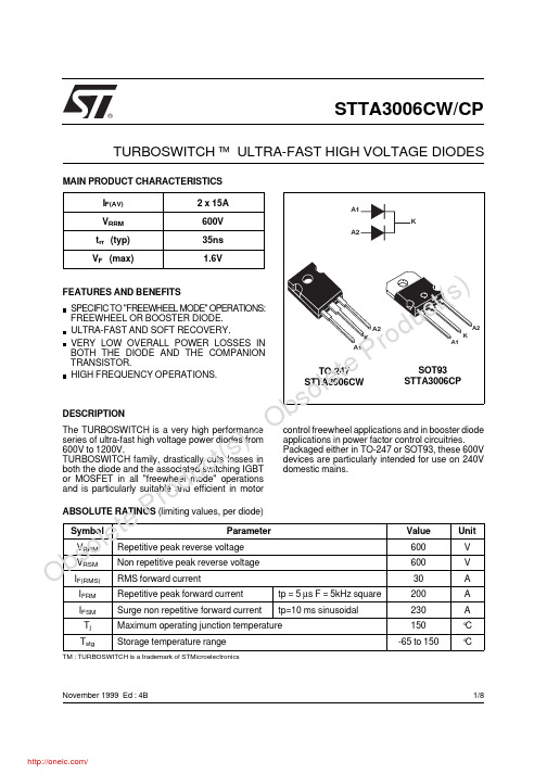
SPECIFIC TO "FREEWHEEL MODE" OPERATIONS:FREEWHEEL OR BOOSTER DIODE.ULTRA-FAST AND SOFT RECOVERY.VERY LOW OVERALL POWER LOSSES IN BOTH THE DIODE AND THE COMPANION TRANSISTOR.HIGH FREQUENCY OPERATIONS.FEATURES AND BENEFITSThe TURBOSWITCH is a very high performance series of ultra-fast high voltage power diodes from 600V to 1200V.TURBOSWITCH family, drastically cuts losses in both the diode and the associated switching IGBT or MOSFET in all "freewheel mode" operations and is particularly suitable and efficient in motor control freewheel applications and in booster diode applications in power factor control circuitries.Packaged either in TO-247 or SOT93, these 600V devices are particularly intended for use on 240V domestic mains.DESCRIPTIONI F(AV) 2 x 15A V RRM 600V t rr (typ)35ns V F (max)1.6VMAIN PRODUCT CHARACTERISTICSSymbolParameter Value Unit V RRM Repetitive peak reverse voltage 600V V RSM Non repetitive peak reverse voltage 600V I F(RMS)RMS forward current30A I FRM Repetitive peak forward current tp = 5 µs F = 5kHz square 200A I FSM Surge non repetitive forward current tp=10 ms sinusoidal230A T jMaximum operating junction temperature150°C T stgStorage temperature range-65 to 150°CTM : TURBOSWITCH is a trademark of STMicroelectronicsABSOLUTE RATINGS (limiting values, per diode)STTA3006CW/CP®TURBOSWITCH ™ ULTRA-FAST HIGH VOLTAGE DIODESA1A2K TO-247STTA3006CWA1A2KNovember 1999 Ed : 4B A1A2KSOT93STTA3006CP1/8Ob s ol e t ePr od u c t (s ) -O bs o l e t eP r od u c t (s)Ob so l e t ePr od u c t (s ) -O bs o l e t eP r od u c t (s) Symbol ParameterTest conditions Min Typ Max UnitV F *Forward voltage drop I F =15A Tj = 25°C Tj = 125°C 1.3 1.81.6VV I R **Reverse leakage current V R =0.8 x V RRM Tj = 25°C Tj = 125°C 21005µA mA V to Threshold voltage Ip < 3.I AVTj = 125°C1.06V rdDynamic resistance177m ΩTest pulse :* tp = 380 µs, δ < 2%** tp = 5 ms, δ < 2%STATIC ELECTRICAL CHARACTERISTICS (per diode)Symbol ParameterTest conditions Value Unit R th(j-c)Junction to casePer diode Total Coupling1.91.00.1°C/WP 1Conduction power dissipation Per diodeI F(AV) = 30A δ =0.5Tc= 110°C 20.5WP maxTotal power dissipationPmax = P1 + P3 (P3 = 10% P1)Per diode Tc=105°C22.5WTHERMAL AND POWER DATASymbol Parameter Test conditionsMinTyp Max Unit t rrReverserecovery timeTj = 25°CI F = 0.5 A I R = 1A Irr = 0.25A I F = 1A dI F /dt =-50A/µs V R = 30V3565nsI RMMaximumreverse recovery current Tj = 125°C V R = 400V I F = 15A dI F /dt = -120 A/µs dI F /dt = -500 A/µs 17.512.5AS factorSoftness factorTj = 125°C V R = 400V I F = 15AdI F /dt = -500 A/µs0.5/DYNAMIC ELECTRICAL CHARACTERISTICS (per diode)TURN-OFF SWITCHINGSymbolParameter Test conditionsMinTypMax Unit t frForwardrecovery time Tj = 25°CI F = 15A, dI F /dt = 120 A/µs measured at, 1.1 × V F max 500nsV FpPeak forward voltageTj = 25°CI F = 15A, dI F /dt = 120 A/µs9VTURN-ON SWITCHINGTo evaluate the maximum conduction losses use the following equation :P = V to x I F(AV) + rd x I F 2(RMS)STTA3006CW/CP2/8Ob s ol e t ePr od u c t (s )- O bs o l e t eP r od u c t (s) 0246810121416180510152025IF(av) (A)P1(W)δ= 1δ= 0.5δ= 0.2δ= 0.1Tδ=tp/TtpFig. 1: Conduction losses versus average current.1E-41E-31E-21E-11E+00.00.20.40.60.81.0K Single pulseδ= 0.1δ= 0.2δ= 0.5K=Zth(j-c) (tp,)δRth(j-c)tp(s)Tδ=tp/TtpFig. 3: Relative variation of thermal transient impedance junction to case versus pulse duration.0.00.5 1.0 1.5 2.0 2.5 3.0 3.5 4.0110100200VFM(V)Tj=125°CIFM(A)Fig. 2: Forward voltage drop versus forward current (maximum values).1002003004005006007008009001000051015202530354045IRM(A)VR=400VTj =125°CIF=IF(av)IF=2*IF(av)IF=0.5*IF(av)dIF/dt(A/µs)Fig. 4: Peak reverse recovery current versus dIF/dt (90% confidence).100200300400500600700800900100020406080100120140160180200trr(ns)VR=400V Tj=125°CIF=0.5*IF(av)IF=2*IF(av)IF=IF(av)dIF/dt(A/µs)Fig. 5: Reverse recovery time versus dIF/dt (90%confidence).S factor10020030040050060070080090010000.00.20.40.60.81.0dIF/dt(A/µs)VR=400V Tj=125°CIF<2*IF(av)Fig. 6: Softness factor (tb/ta) versus dIF/dt (typical values).STTA3006CW/CP3/8Ob so l e t ePr od u c t (s ) -O bs o l e t eP r od u c t (s) 2550751001250.70.80.91.01.1Tj(°C)IRMS factorFig. 7: Relative variation of dynamic parameters versus junction temperature (reference Tj=125°C).10020030040050060070080090010000510152025VFP(V)Tj=125°CIF=IF(av)dIF/dt(A/µs)Fig. 8: Transient peak forward voltage versus dIF/dt (90% confidence).100200300400500600700800900100050100150200250300tfr(ns)Tj=125°CVFR=1.1*VF max.IF=IF(av)dIF/dt(A/µs)Fig. 9: Forward recovery time versus dIF/dt (90%confidence).STTA3006CW/CP4/8Ob s o l e t ePr od u c t (s ) -O bs o l e t eP r od u c t (s) Fig. A : "FREEWHEEL" MODE.TOTAL LOSSES due to the diodeP = P1+ P2+ P3+ P4+ P5 WattsSWITCHING LOSSES in the diode SWITCHING LOSSES in the tansistorCONDUCTION LOSSES in the diode REVERSE LOSSES in the diode The TURBOSWITCH is especially designed to provide the lowest overall power losses in any "FREEWHEEL Mode" application (Fig.A)considering both the diode and the companiontransistor, thus optimizing the overall performance in the end application.The way of calculating the power losses is given below:APPLICATION DATADIODE:TURBOSWITCHILLOADTRANSISTORSWITCHING t TF =1/T =t/TV RSTTA3006CW/CP5/8Ob so l e t ePr od u c t (s )- O bs o l e t eP r od u c t (s) Turn-on losses :(in the transistor, due to the diode)P5 =V R × I RM 2 × ( 3 + 2 × S ) × F6 x dI F ⁄ dt+V R × I RM × I L × ( S + 2 ) × F 2 x dI F ⁄ dtTurn-off losses (in the diode) :P3 =V R × I RM 2 × S × F6 x dI F ⁄ dtP3 and P5 are suitable for power MOSFET and IGBTI I FRdI RV RV tOV FVFig. B: STATIC CHARACTERISTICSVIILtTRANSISTORdI /dtF dI /dtR tbta I RMVRDIODEIVt trr =ta +tbS =tb /taFig. C: TURN-OFF CHARACTERISTICSI F V FV Fp1.1V FV F F dI /dt00ttI FmaxtfrFig. C: TURN-ON CHARACTERISTICSConduction losses :P1 = V t0 . I F(AV) + R d . I F 2(RMS)Reverse losses :P2 = V R . I R . (1 - δ)Turn-on losses :P4 = 0.4 (V FP - V F ) . I Fmax . t fr . FAPPLICATION DATA (Cont’d)STTA3006CW/CP6/8Ob so l e t ePr od u c t (s ) - O bs o l e t eP r od u c t (s) PACKAGE DATA TO-247 PlasticREF.DIMENSIONSMillimeters InchesMin.Typ.Max.Min.Typ.Max.A 4.85 5.150.1910.203D 2.20 2.600.0860.102E 0.400.800.0150.031F 1.001.400.0390.055F13.000.118F2 2.000.078F3 2.00 2.400.0780.094F4 3.003.400.1180.133G 10.900.429H15.4515.750.6080.620L 19.8520.150.7810.793L1 3.704.300.1450.169L218.500.728L314.2014.800.5590.582L434.60 1.362L5 5.500.216M 2.003.000.0780.118V 5°5°V260°60°Dia.3.553.650.1390.143F2F1V2L4L2L1L3DLL5MEHVVADia.F3F4G = =F(x3)Cooling method : by conduction (C).Recommended torque value : 0.8 m.N Maximum torque value : 1 m.NSTTA3006CW/CP7/8Ob so l e t ePr od u c t (s ) -O bs o l e t eP r od u c t (s) Information furnished is believed to be accurate and reliable. However, STMicroelectronics assumes no responsibility for the consequences of use of such information nor for any infringement of patents or other rights of third parties which may result from its use. No license is granted by implication or otherwise under any patent or patent rights of STMicroelectronics. Specifications mentioned in this publication are subject to change without notice. This publication supersedes and replaces all information previously supplied.STMicroelectronics products are not authorized for use as critical components in life support devices or systems without express written ap-proval of STMicroelectronics.The ST logo is a registered trademark of STMicroelectronics © 1999 STMicroelectronics - Printed in Italy - All rights reserved.STMicroelectronics GROUP OF COMPANIESAustralia - Brazil - China - Finland - France - Germany - Hong Kong - India - Italy - Japan - MalaysiaMalta - Morocco - Singapore - Spain - Sweden - Switzerland - United Kingdom - U.S.A.Cooling method : by conduction (C).Recommended torque value : 0.8 m.N Maximum torque value : 1 m.N PACKAGE DATA SOT93 PlasticREF.DIMENSIONSMillimeters Inches Min.Typ.Max.Min.Typ.Max.A 4.70 4.90 1.1850.193C 1.902.100.0750.083D 2.500.098D1 2.000.078E 0.500.780.0200.031F 1.101.300.0430.051F3 1.750.069F4 2.100.083G 10.8011.100.4250.437H 14.7015.200.2790.598L 12.200.480L216.200.638L318.00.709L5 3.95 4.150.1560.163L631.001.220O4.00 4.100.1570.161Ordering type MarkingPackage Weight Base qty Delivery modeSTTA3006CW STTA3006CW TO247 4.36g 30Tube STTA3006CPSTTA3006CPSOT933.97g30TubeEpoxy meets UL94,V0STTA3006CW/CP8/8分销商库存信息: STMSTTA3006CW。
IC测试设备
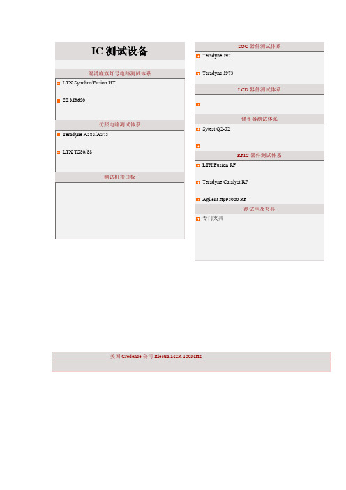
IC测试设备混淆旌旗灯号电路测试体系LTX Synchro/Fusion HTSZ M3650仿照电路测试体系Teradyne A585/A575LTX TS80/88测试机接口板SOC器件测试体系Teradyne J971Teradyne J973LCD器件测试体系储备器测试体系Sytest Q2-52RFIC器件测试体系LTX Fusion RFTeradyne Catalyst RFAgilent Hp93000 RF测试座及夹具专门夹具美国Credence公司Electra MSR 100MHz美国Credence公司Electra MSR 100MHz概述·100MHz量测速度的功能验证性设备,具有Funtional Pattern产生、仿真、测试,DC参数量测等功能。
·专门合适IC设计公司进行样片芯片验证性测试及分析特点:·4M的向量储备深度/通道完全的功能Pattwen和DC参数测试体系·UNIX体系的操作软件,可视化友爱界面·Shmoo Plot对象, 用于器件特点分析 ·可连接LABVIEW关心性对象·直截了当连接到工作站办事器体系规格·时钟频率:100 Mhz·数据速度:200 Mbits/Sec·1.5 ns的上升和降低时刻(ECL、CMOS 电路)·每个管脚的电压和负载可编程·每个管脚可编程边沿辨论率50 ps·7 bits per Channel for Simultaneous Real-time ·Compare and Data Acquisition·时钟线形稳固,误差≦±100 ps ·体系误差≦±1ns (ATS1)·每个管脚可选用直流周详测量单位·Window、Edge和Dual-Edge 采样·128个I/O管脚(ATS1) ·APMU:直流周详测量单位·2.1 Gb扩大图形储备器·PCI-GPIB 和PCI-VXI接口板·Sun Ultra 10 工作站体系软体功能·TestEnv:基于Xwindows的测试软件情形,包含·IMS Screens、IMS-Shmoo、TestLITE和·MATSS测试办事器·IMS-Link:供给脱机向量转换软件编辑才能和通用仿真器支撑·TestVIEW (V7.2e) :图形测试编程说话体系模组Module·Control Module x1 ·Timing module x1 · Data module x8 ·Analytical DC PMU module x1Socket Card 种类及数量·DIP Auto Socket Card 40 *1·ATS1/MSTS1 Anolog Interface Board *1 ·Force Autocal Interface Board *1 ·Open Custom DUT Interface Board *13·ATS1/MSTS Fixture Board *1·Force Autocal *1·Compare Autocal *1·IMS Adapter Board *1台湾德律TR-6010 逻辑器件测试机概述:·专为10MHz逻辑IC测试机, 具有Function Pattern测试, Dc 参数量测等功能硬件构造:特点:·2M的向量储备器深度·可4组并行测试·完全的功能Pattwen和DC参数测试·驱动电压:+-8V,比较电压:6V ·具有Shmoo Plot对象, 用于器件特点分析·测试法度榜样调试对象·完美的测试诊断申报和柱状图·TTL和GPIB接口, 可直截了当连接至prober和handler ·紧凑小型,易安装资本设备:·测试操纵器:奔驰III以上PC ·体系软件:MS-DOS ·电源要求:(1)单订交换,AC 110V 10A /50-60Hz (2)单订交换,AC 220V 6A /50-60Hz机能参数:·测试频率:10MHz·周期速度:100nS-1.31mS ·周期辨论率:20nS·测试通道:最大年夜128个·多组测试:2/4组并行测试·准时器:4Pins/TG·准时器辨论率:10nS ·闸门模式:边沿式·测试向量深度:2M·驱动器:VIH:+-8V 辨论率:5mV ·VIL:+-8V 辨论率:5mV·比较器:VOH:+-8V 辨论率:5mV ·VOL:+-8V 辨论率:5mVPMU:1组/板卡,最大年夜8组施加电压/ 测量电流范畴:级别电压精确度辨论率0 10V +%+-5mV 2.5mV1 10V +%+-5mV 2.5mV2 10V +%+-5mV 2.5mV3 10V +%+-5mV 2.5mV 施加电流/ 测量电压范畴:HVPMU:2组/板卡,最大年夜16组施加电压/ 测量电流范畴:施加电流/ 测量电压范畴:日本VTT公司V777大年夜范畴集成电路逻辑测试体系(一)概述·10MHz的测试频率,128个测试通道,4M字节向量深度的大年夜范畴LSI测试体系体系尺寸·主框架:580(W),750(D),1200(H)或1850(H)毫米·测试头:580(W),340(D),250(H)毫米·电缆长度:4 米测试器操纵器·处理器AMD-K6-500 ·操作体系MS/DOSV ·内存32MB·硬盘4.0GB·软盘3.5英寸1.44MB接口板·标准接口板针对探针机和机械手·GPIB 接口板选项PIN电子机能·标准64 PIN·全体系128 PIN 或64PIN*2DUTS软件包·说话 C (库: TURBO C)·对象软件SCHMOOHISTOGRAMWAFERMAP ·测试法度榜样转换器ANDO-SUMMIT 至V7100 (主法度榜样和波形法度榜样) SENTRY 至V7100 (波形法度榜样)CREDENCE-SC212 至V7100 (波形法度榜样)ADVANTEST-MOSPL 至V-7100 (波形法度榜样)驱动器·输出电压VIH 0V 至+11V VIL -2V 至+8V ·电压摆幅100mVp-p 至11Vp-p·精度0.5% + 5mV·辨论率2.7mV·最大年夜DC 电流输出="H"±20mA 输出= "L"±20mA·阻抗50 ± 5%ohm·升/ 降时刻驱动器模式< 5ns/5Vp-p(20% 至80%) I/O 模式< 5ns/5Vp-p ·总时钟精度 (NRZ 格局) ±5ns ( 最大年夜 ) ·时滞 (NRZ 格局 ) 有关PINS ±5ns ( 最大年夜 )·有关TGS ±4ns ( 最大年夜 )·上突波 / 下突波 3%+50mV· VIH/VIL 级别 4 级别·驱动器模式 FIX-HI, FIX-LO, NRZ, /NRZ, RZ, /RZ, R1, EXOR, /EXOR,·无调制·时钟的限制参照图 1前提: 10Mohm 和 15pF 载荷安捷伦83000 数字电路测试体系描述:特点和用处:·用于Credence的Electra MSR 100MHz机台上,依照客户器件封装尺寸设计制造专用的定制型测试接口板,有效解决高速旌旗灯号干扰之问题。
- 1、下载文档前请自行甄别文档内容的完整性,平台不提供额外的编辑、内容补充、找答案等附加服务。
- 2、"仅部分预览"的文档,不可在线预览部分如存在完整性等问题,可反馈申请退款(可完整预览的文档不适用该条件!)。
- 3、如文档侵犯您的权益,请联系客服反馈,我们会尽快为您处理(人工客服工作时间:9:00-18:30)。
In keeping with our ongoing policy of product evolvement and improvement, the above specification is subject to change without notice.ISO9001: 2000 Registered - Registration number 6830/2 For quotations or further information please contact us at:3 The Business Centre, Molly Millars Lane, Wokingham, Berks, RG41 2EY, UKThe ACTR3006/310.0/QCC4A is a true one-port, surface-acoustic-wave (SAW ) resonator in a surface-mount ceramic QCC4A case. It provides reliable, fundamental-mode, quartz frequency stabilization i.e. in transmitters or local oscillators operating at 310.000 MHz.1.Package Dimension (QCC4A)3.Equivalent LC Model and Test Circuit4.Typical Application Circuits1) Low-Power Transmitter Application 2) Local Oscillator ApplicationPinConfiguration 1 Input / Output 3 Output / Input 2/4Case GroundSign Data (unit: mm)Sign Data (unit: mm)A 1.2 D 1.4B 0.8 E 5.0 C0.5F3.5Issue : 1 C1 Date : SEPT 04In keeping with our ongoing policy of product evolvement and improvement, the above specification is subject to change without notice.ISO9001: 2000 Registered - Registration number 6830/2 For quotations or further information please contact us at:3 The Business Centre, Molly Millars Lane, Wokingham, Berks, RG41 2EY, UK5.Typical Frequency Response6.Temperature Characteristics7.Performance7-1.Maximum RatingsRatingValueUnitsCW RF Power Dissipation 0 dBm DC Voltage Between Terminals ±30V VDC Case Temperature -40 to +85 °C Soldering Temperature+250°C7-2.Electronic CharacteristicsCharacteristicSymMinimumTypicalMaximumUnitsAbsolute Frequency f C 309.925310.075MHz Centre Frequency(+25°C ) Tolerance from 310.000MHz∆f C ±75 kHz Insertion Loss IL 1.1 1.8 dB Unloaded Q Q U 15,150 Quality Factor50 Ω Loaded Q Q L 1,800 Turnover TemperatureT 0 25 55 °CTurnover Frequencyf 0 f C kHz Temperature StabilityFrequency Temperature CoefficientFTC 0.03 ppm/ °C 2 Frequency Aging Absolute Value during the First Year |f A | ≤10 ppm/yr DC Insulation Resistance Between Any Two Terminals1.0 M Ω Motional ResistanceR M 13.5 23 Ω Motional Inductance L M 104.9414 µH Motional Capacitance C M 2.5143 fF RF Equivalent RLC ModelShunt Static Capacitance C 02.42.73.0pFi CAUTION: Electrostatic Sensitive Device. Observe precautions for handling!Issue : 1 C1 Date : SEPT 04In keeping with our ongoing policy of product evolvement and improvement, the above specification is subject to change without notice.ISO9001: 2000 Registered - Registration number 6830/2 For quotations or further information please contact us at:3 The Business Centre, Molly Millars Lane, Wokingham, Berks, RG41 2EY, UK1. The centre frequency, f C , is measured at the minimum IL point with the resonator in the 50Ω test system.2. Unless noted otherwise, case temperature T C = +25°C±2°C.3. Frequency aging is the change in f C with time and is specified at +65°C or less. Aging may exceed thespecification for prolonged temperatures above +65°C. Typically, aging is greatest the first year after manufacture, decreasing in subsequent years.4. Turnover temperature, T 0, is the temperature of maximum (or turnover) frequency, f 0. The nominal frequency atany case temperature, T C , may be calculated from: f = f 0 [1 - FTC (T 0 - T C )2].5. This equivalent RLC model approximates resonator performance near the resonant frequency and is providedfor reference only. The capacitance C 0 is the measured static (non-motional) capacitance between the two terminals. The measurement includes case parasitic capacitance.6. Derived mathematically from one or more of the following directly measured parameters: f C , IL, 3 dB bandwidth,f C versus T C , and C 0.7. The specifications of this device are based on the test circuit shown above and subject to change orobsolescence without notice.8. Typically, equipment utilizing this device requires emissions testing and government approval, which is theresponsibility of the equipment manufacturer.9. Our liability is only assumed for the Surface Acoustic Wave (SAW) component(s) per se, not for applications,processes and circuits implemented within components or assemblies.Issue : 1 C1 Date : SEPT 04。
