T-7700调试手册
安捷伦 7700 中文版

非凡设计无双性能令人耳目一新的ICP-MSAgilent 7700系列ICP-MSOur measure is your success.产品|应用|软件|服务Agilent 7700系列ICP-MS推动ICP-MS技术发展,简化痕量元素分析无论您是想以最快的速度分析成百上千个基体复杂的样品,还是想要获得高纯试剂中超痕量杂质的最可信结果,安捷伦7700 系列ICP-MS都能助您满足当前以及未来的分析需求。
安捷伦7700系列ICP-MS– ICP-MS仪器的新面孔– 是世界上最小的商品化ICP-MS。
作为最畅销的安捷伦7500系列ICP-MS的继承者,7700性能在各方面更胜一筹:分析速度更快、操作更简便、灵敏度更高、背景噪音更低、消干扰效果更佳、应用面更广、维护更方便。
7700系列ICP-MS不但配置了新的软件平台,而且在仪器硬件方面也进行了革新设计,包括全新数字控制式射频匹配的RF 发生器和第三代八极杆碰撞/反应池系统(ORS3)。
7700x具有适应多种样品类型、应用范围广泛、性能稳定耐用的特点,是大多数常规实验室和分析大批量样品的商业实验室的最优选择。
7700s则是专为半导体行业应用而设计,具有半导体针对性的强大功能。
这两种型号都具有无可比拟的性能和易于使用的优点,即使您面对的是最棘手的样品基体,它们都能为您获取值得信赖的分析结果。
安捷伦7700x ICP-MS凭借第三代碰撞/反应池(ORS3)为复杂高基体样品的分析提供了无可比拟的准确性,它革命性地重新定义了碰撞/反应池:仅使用氦气碰撞即可消除所有可能的质谱干扰!欲了解有关安捷伦7700系列ICP-MS的更多信息,请访问/chem/ICPMS:cn杰出的第三代ICP-MS过去20多年来,安捷伦公司作为ICP-MS技术发展的重要推动力量,推出了许多原创性的领先技术。
7700将更进一步将ICP-MS 带入不依靠专家的时代,它广泛进入常规的实验室面对一般操作人员,而其分析性能、可靠性和自动化方面达到了最新标准。
WTY-871技术及使用说明书 V1.01

3
装置功能 .......................................................................................................................................................................... 6 3.1 FC 回路保护(厂用变、电动机保护配置) ........................................................................................................ 6 3.2 (低压闭锁)过流保护(线路保护配置) .......................................................................................................... 6 3.3 复压闭锁过流保护(厂用变保护配置) .............................................................................................................. 6 3.4 过流保护(电容器、电动机保护配置) .............................................................................................................. 7 3.5 反时限过流保护(线路、厂用变、电容器、电动机保护配置) .........................................................
电子巡更软件使用手册
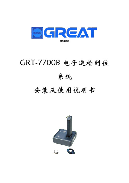
(格瑞特)GRT-7700B电子巡检到位系统安装及使用说明书GRT-7700B使用手册说明首先感谢您选用GRT-7700系列电子巡检系统软件,GRT-7700B电子巡检系统软件包括一张光盘及配套的软件加密狗一只,在开始安装及使用该软件之前,请仔细阅读本使用手册。
一.安装硬件安装:* 请您先检查我们向您提供的产品,包括信息采集器、信息变送器、信息钮(巡更点)、软件(光盘和加密狗)、通讯线等。
*请首先将通讯线的一端RJ45(电话)接口,接入变送器的RJ45接口端,再将我们所提供的变压器电源接入变送器。
将通讯线的另一端RS232接口与电脑的COM 1或COM 2(串口1或2)相连,并记住所连接的是COM 1还是COM 2,另外将“加密狗”插在打印机端口LPT1上。
*信息钮(巡更点)的安装,(请在软件安装完成后再操作此步骤),信息钮的安装有两种方法:如购买厚型信息钮(DS-1990A F5)可选购固定基座安装;也可购买我们为您提供的专用安装胶水,使用胶水的方法是:先将信息钮的背面及所要粘的地方均涂上适量的胶水,等待5-10分钟再将这两面粘合,再待24小时后就会完全干透(注:该胶水应粘在坚实,干净的平面上)。
软件安装系统配置要求:CPU为Intel celeron 300MHz以上,内存64M以上,硬盘2.1G以上软件运行环境为Win9x /Me& Win2000/XP。
将安装光盘放入光驱,光盘包含三个文件,(setup.exe, setup.lst, xungengsystem.cab)执行setup.exe文件进行安装,依提示进行安装。
软件缺省安装在C:\ProbeNew目录中,安装时用户也可以修改目录名,以使软件安装在其它任何目录中。
但不要安装在\programe files等目录名称之间有空格的目录下,且必须用不多于8个英文字母的目录名。
安装过程中系统可能(视用户电脑)会提示要复制的文件比系统中现存的文件要旧,请选择“是”以保存原有文件。
产品型号T-7700

7、具有 3.5mm 耳机接口、3.5mm 话筒输入接口。
8、具有短路输出接口、短路输入接口。
9、支持通过后台对终端进行远程升级。
10、信噪比≥65dB,总偕波失真≤1%,LIEN OUT 频率响应:80Hz~
16KHz,输出电平:1000mV。
其它配套设备
产品型号:T-7707
1、设备壁挂式设计,设备采用嵌入式计算机技术和 DSP 音频处
2、可以指定一个话筒具有最高优先、强行切入优先功能,其和
广州市保
前置放 EMC 最高优先权限功能可交替选择; 1
大器 3、4 路紧急输入线路具有二级优先,强行切入优先功能;
伦电子有
itc
1500 1 台 1500 无
限公司
4、所有 MIC 输入 和 2 路紧急输入(EMC)通道均附设有线路辅
(广州)
序 货物名 号称
技术规格、型号
制造商
品牌
单价
(产地)
一、广播中心机房主控设备
主机服务器
产品型号:T-7700
1、采用工业级工控机机箱设计,具有 15 英寸 LED 液晶显示屏,
支持触摸控制屏;服务器要求运载 windows server 操作系统。
2、支持 1 路短路触发开机接口,用于实现定时驱动开机运行。
2.大屏幕液晶显示屏,图形化界面,操作简单。可显示所有被
控制电源状态指示、日期、星期、时间、下一步程序的信息等。
广州市保
智能控 3.具备钟声输出接口,报警短路信号输入接口。 2
制主机 4.具备触发控制短路信号输出接口,可触发报警器等设备。
伦电子有
itc
3000 1 台 3000 无
限公司
5.设有短路触发输出接口,可控制十六位电源时序器开关,扩
T-7700RP T-7700TP IP网络广播系统第二版使用手册V1.1

T-7700RP T-7700TP IP网络广播系统第二版使用手册V1.1概述T-7700RP T-7700TP IP网络广播系统第二版(以下简称系统)是一款基于IP网络的广播系统。
本手册旨在介绍系统的安装、配置和使用方法,以帮助用户顺利使用该系统。
系统要求在使用系统之前,请确保满足以下硬件和软件要求:硬件要求•T-7700RP 或 T-7700TP 广播终端•有线或无线网络连接•支持TCP/IP协议的路由器•扬声器或耳机软件要求•Windows 7 或更新的操作系统•最新版本的浏览器(建议使用Chrome)安装与配置1. 连接广播终端将T-7700RP 或 T-7700TP 广播终端通过网线连接到您的局域网中的路由器。
如果您使用的是无线网络,您需要将广播终端配置为连接到您的无线网络。
2. 配置广播终端在您的电脑上打开浏览器,输入广播终端的IP地址,然后按Enter键。
您可以通过查阅广播终端的用户手册获取其默认IP地址。
在浏览器中,您将看到一个登录页面,请输入正确的用户名和密码登录。
3. 设置网络参数一旦成功登录,您将看到系统的控制面板。
在控制面板中,您可以设置广播终端的网络参数,例如IP地址、子网掩码和网关。
确保这些参数与您的网络环境相匹配。
4. 配置音频设置在控制面板中,您还可以配置广播终端的音频设置。
您可以选择扬声器或耳机作为音频输出设备,并调整音量。
确保音频设置正确,以便您能够听到广播内容。
使用方法1. 创建广播列表在控制面板中,您可以创建广播列表。
广播列表是指广播终端将要播放的音频文件集合。
您可以选择上传音频文件或输入音频文件的URL。
添加音频文件后,您可以调整它们的播放顺序并设置循环播放。
2. 发起广播一旦创建了广播列表,您可以使用控制面板上的“播放”按钮发起广播。
广播终端将按照设置的顺序播放广播列表中的音频文件。
您可以随时暂停、恢复或停止广播。
3. 调整音量在广播过程中,您可以通过控制面板上的音量滑块调整音频的音量。
安捷伦7700和7500Masshunter快速入门指南

• AMU Gain • AMU Offset • P/A Factor • Analog HV • Discriminator
• Torch-H • Torch-V • Pulse HV • Axis Offsystem Wide Parameters 列表中: a 单击以选择 Tune Parameters 列表中的某一项。 b 按下 <Ctrl> 键并单击选择其他调谐参数。 c 单击 Add-> 按钮以将选定的调谐参数移入 System Wide Parameters 列表中。
点燃等离子体
1 采用以下方式之一打开 Instrument Control 面板: • 从 Instrument 菜单中选择 Instrument Control,或者 • 单击 Instrument Control 图标。 此时将打开 ICP-MS Instrument Control 面板:
2 通过检查 Instrument Control 面板的标题栏,确认仪器处于待机模式下。 3 通过单击工具栏上的 Ignite Plasma 图标,点燃等离子体。 4 当等离子体点燃且仪器从待机模式变为分析模式后,请按照以下部分所述检查
调谐说明 请参见 《Agilent 7500 Series ICP-MS Tuning & Application Handbook》。
完整信息 请参见联机帮助或 《Agilent 7500 Series ICP-MS MassHunter Workstation (G7200A) Operator’s Manual》。
智能序列 请参见 《Agilent Intelligent Sequence Software Manual》。
ATC770中文说明书

DyniscoInstruments带有微处理器的ATC770压力/过程控制器安装和使用手册(中文版)本手册译自:DyniscoInstrumentsINSTALLATION & OPERATION MANUALATC 770 MICROPROCESSOR-BASEDPRESSURE/PROCESS CONTROLLER本中文版说明书力图在尽可能多的方面忠实于原英文说明书,但对准确性不做承诺。
如有任何疑问请参阅原英文说明书注意:本中文版说明书保有不先行通知即行修改的权利DyniscoInstrumentsATC770-0-2-3表快速入门1.安装. 按如下尺寸准备安装口。
.移开锁紧卡,以便将仪表从机壳中抽出。
.抓紧机壳将仪表抽出装在机壳上。
.将橡胶垫圈装在壳体。
.将机壳插入开好的安装口。
. 放入面板紧固件,将紧固螺丝旋入拧紧。
.将仪表插回机壳,直到听到喀的一声,表示安装到位。
2. 接线.按接线端子图所注连接传感器。
.连接控制执行设备。
.如带报警功能,连接报警.注意:报警2,3的出厂设置是高、反向动作;报警1是低禁止的。
.按图所示务必正确连接电源。
6.1 端子配置3.线性-远程S.P4.线性-远程S.P红→ 12.应变片信号+或线性+黑→ 13.应变片信号-或线性-橙→ 14.校正2白→ 16.激励+蓝/绿→ 17.激励-,校正121.控制输出 mA/V+22.控制输出 mA/V-23.远程复位24. 远程复位输出45.报警1,常开46. 报警1,公共端47.报警1,常闭48. 报警2,常开49. 报警2,公共端50.报警2,常闭51.报警3,公共端52.报警3, 常闭/常开53.100-240VAC(交流电)54.LN(交流零线)56.模拟输入中继输出 mA/V+57.模拟输入中继输出 mA/V-58.24VDC辅助电源输出+59.24VDC辅助电源输出+60.RS-485:A/A’61.RS-485:B/B’62.RS-485:数字输入公共端63.数字输入164.数字输入265.数字输入366.数字输入43. 设置量程.给仪表加电.上位显示窗将显示一个近零值。
电子巡更软件使用手册范本

(格瑞特)GRT-7700B电子巡检到位系统安装及使用说明书GRT-7700B使用手册说明首先感您选用GRT-7700系列电子巡检系统软件,GRT-7700B电子巡检系统软件包括一光盘及配套的软件加密狗一只,在开始安装及使用该软件之前,请仔细阅读本使用手册。
一.安装硬件安装:* 请您先检查我们向您提供的产品,包括信息采集器、信息变送器、信息钮(巡更点)、软件(光盘和加密狗)、通讯线等。
*请首先将通讯线的一端RJ45()接口,接入变送器的RJ45接口端,再将我们所提供的变压器电源接入变送器。
将通讯线的另一端RS232接口与电脑的COM 1或COM 2(串口1或2)相连,并记住所连接的是COM 1还是COM 2,另外将“加密狗”插在打印机端口LPT1上。
*信息钮(巡更点)的安装,(请在软件安装完成后再操作此步骤),信息钮的安装有两种方法:如购买厚型信息钮(DS-1990A F5)可选购固定基座安装;也可购买我们为您提供的专用安装胶水,使用胶水的方法是:先将信息钮的背面及所要粘的地方均涂上适量的胶水,等待5-10分钟再将这两面粘合,再待24小时后就会完全干透(注:该胶水应粘在坚实,干净的平面上)。
软件安装系统配置要求:CPU为Intel celeron 300MHz以上,存64M以上,硬盘2.1G以上软件运行环境为Win9x /Me& Win2000/XP。
将安装光盘放入光驱,光盘包含三个文件,(setup.exe, setup.lst, xungengsystem.cab)执行setup.exe文件进行安装,依提示进行安装。
软件缺省安装在C:\ProbeNew目录中,安装时用户也可以修改目录名,以使软件安装在其它任何目录中。
但不要安装在\programe files等目录名称之间有空格的目录下,且必须用不多于8个英文字母的目录名。
安装过程中系统可能(视用户电脑)会提示要复制的文件比系统中现存的文件要旧,请选择“是”以保存原有文件。
7700系列ip广播布线规范
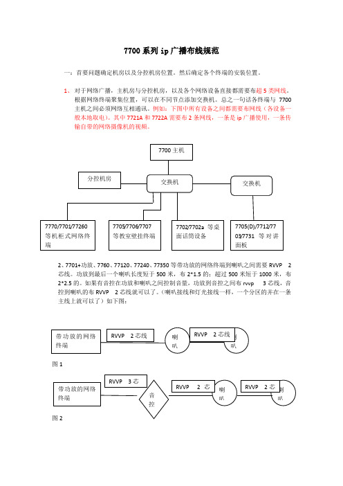
7700系列ip 广播布线规范一:首要问题确定机房以及分控机房位置。
然后确定各个终端的安装位置。
1、 对于网络广播,主机房与分控机房,以及各个网络设备直接都需要布超5类网线。
根据网络终端聚集位置,可以在不同节点添加交换机。
总之一句话各终端与7700主机之间必须网络互相通讯。
例如:下图中所有设备之间都需要布网线(各设备一般本地取电)。
其中7721A 和7722A 需要布2条网线,一条是ip 广播使用,一条传输自带的网络摄像机的视频。
2、7701+功放、7760、77120、77240、77350等带功放的网络终端到喇叭之间需要RVVP 2芯线。
功放到最后一个喇叭长度短于500米,布2*1.5的;超过500米短于1000米,布2*2.5的。
如果有音控在功放和喇叭之间控制音量,功放到音控之间布rvvp 3芯线,音控到喇叭的布RVVP 2芯线就可以了。
(喇叭接线和灯光接线一样,一个分区的并在一条主线上就可以了)如下图: 图1二:举例说明各类别设备接线方式(1)、主机T-7700安放主机房,需要有电源供电,然后一条网线连接到广播网络。
(2)桌面寻呼话筒T-7702、T-7702A安放主机房、分机房监控中心服务台等地方,需要有电源供电,然后一条网线连接到广播网络。
(3)网络音箱T-7707/T-7707BM/T-7707BG安放主机房、分机房、等地方作为监听音箱,或者安装在教室、房间等地方作为点对点终端。
需要有电源供电,然后一条网线连接到广播网络。
主音箱到辅音箱之间也布RVVP 2*1.5的线。
(4)网络适配器T-7705、T-7705A、T-7705B、T-7705BM、T-7705C、T-7705U、T-7706、T-7752、T-7735、T-7715A这些终端接外接定压音箱,或者定阻音箱,需要有电源供电,然后一条网线连接到广播网络。
终端到外接的音箱之间布RVVP 2*1.0的线。
(5)网络适配器T-7708、T-7708L、T-7709此类终端需要外接功放,需要有电源供电,然后一条网线连接到广播网络。
Epson ET-7700SP 产品说明书

quality. Press the OK button to continue.
Note: You can change these settings later using the product’s control panel. For more information, see the online User’s Guide.
9 Raise the control panel, then press the power button to
turn on the product.
3 Load paper
See the online User’s Guide for information about available paper types and sizes, loading capacity, rear feed loading, and loading CD/DVD/Blu-ray™ discs.
LCD screen, press the start button to start charging the ink. Ink charging takes approximately 7 minutes. A message appears when ink charging is complete. Press the OK button to continue.
Extra maintenance box
Note: • Do not open the ink bottles until you are ready to fill the ink tanks.
TS7700 发行说明 – 8.33.2.9 (R3.3 PGA 2)说明书

TS7700 Release Notes – 8.33.2.9 (R3.3 PGA 2)IBM System Storage TS7700Release Notes for the TS7700 (3957 VEB / V07) -EC: M13888 released January 13, 2017New Function Supported:- A new LI REQ command for grid resiliencyNew function support description:A new Grid Resiliency Library Request command has been introduced to help analyze timing metrics between clusters in a TS7700 Grid configuration. Using the results of this new command, potential issues or bottlenecks can be discovered sooner within such configurations. Details will be described within an updated version of the "IBM TS7700 Series z/OS Host Command Line Request User's Guide".TS7700 CODE COMPONENTS:PROBLEM FIXES:Problems fixed in this level are described below. There are 96 defects fixed in this release; 49 of them occurred or were related to problems in client installations. They are described below with the following designations:HIPER = High Impact & Pervasive (3 or more occurrences)High Impact = Loss of access or loss of data (less than 3 occurrences)Acute = A unrecoverable error with potential loss of dataSerious = A unrecoverable error with potential loss of access to dataModerate = A system path is not operational and performance might be degradedService = A recoverable error, Service ImprovementsImprovement = Improvement for better usabilityPervasive: problems with 3 or more occurrencesHIPER: Data inconsistent across grid after sync mode write completes successfullyDev fix description: Code logic change to fail write if all target clusters cannot be written in sync modePervasive: YesRef: 81172HIPER: Code upgrade on cluster caused internal conflict in other clusters (mixed code levels across grid)Dev fix description: propagate VPD updates to all clusters during upgradePervasive: YesRef: 80489 (also fixed in vtd_exec.246 v1.03)High Impact: Internal error recovery caused host job failureDev fix description: Code logic improved to avoid incorrect recoveryPervasive: YesRef: 81291High Impact: Prevent error recovery from isolating a cluster during grid joinDev fix description: Improve error recovery process by validating cluster data from gridPervasive: NoRef: 81766High Impact: TVC selection hung in loop and overflowed logs (unexpected reboot required)Dev fix description: Code logic error to identify condition, create additional logs, and exit loopPervasive: NoRef: 81528High Impact: - File system manager error doesn't generate any sim or trigger Call HomeDev fix description: - Parse MMFS error into format_sim (design change)Pervasive: NoRef: 81210High Impact: cluster restarted unexpectedly as internal process management stopped incorrect componentDev fix description: improve code logic from previous fix (Ref: 79156)Pervasive: NoRef: 80548 (also fixed in vtd_exec.238 v. 2.00+)High Impact: Cluster operations left with 3584 library paused after service completed; host jobs failedDev fix description: Library management code logic change to prevent persistence of 3584 library offline condition Pervasive: NoRef: 80374High Impact: cluster restarted unexpectedly from internal DB2 stateDev fix description: Change code logic to abort the process getting stuckPervasive: NoRef: 80328Serious: FICON adapter internal test disrupts adapter initialization (adapter left offline)Dev fix description: Code logic improvement to remove initialization conflictPervasive: YesRef: 80713Serious: Networks with regular interruptions cause many messages on link state (possible MQ stall/reboot required) Dev fix description: Change code logic to use AIX setting to improve network reliabilityPervasive: YesRef: 80377 (also fixed in vtd_exec.227 v. 1.04)Serious: Host job abends after internal grid code errorDev fix description: Grid code retry added for temporary error conditionPervasive: YesRef: 80208Serious: Multiple cancels to Flash Copy DR test caused cluster recovery (automatic data resync with other clusters after DB2 table deleted)Dev fix description: Code logic change to prevent multiple LI REQ from remote clusterPervasive: NoRef: 81556Serious: FICON adapter restarted when cancel received during Busy status sequence for Read CCWDev fix description: Code logic change to send device end only when a cancel comes during BUSY status. The cancel operation will be deferred to following process.Pervasive: NoRef: 81141Serious: Detailed database snapshot information missing for analysis when required for upgrade failureDev fix description: Enable additional database monitor switches during activation process to increase detail in logs. Pervasive: NoRef: 81047Serious: Mount pending for EKM communication (problem not understood)Dev fix description: add logging for error condition observedPervasive: NoRef: 80609Serious: DB2 write to system hard drive fails; drive not failed (cluster restart required)Dev fix description: Add code logic to monitor DB2 log for failure and provide additional diagnostics for service Pervasive: NoRef: 79006Serious: Unjoin of cluster delayed from DB2 background reorg running simultaneously (extended outage)Dev fix description: Pause background DB reorg process during unjoinPervasive: NoRef: 78582Serious: FICON adapter restart after host cancel CCWDev fix description: Code logic errorPervasive: NoRef: 79796Serious: Replacement of system board extended from code logic error (extended service window)Dev fix description: Correct the code logic in system replacement procedurePervasive: NoRef: 79606 (also fixed in vtd_exec.256 v. 1.01)Serious: During code activation a hardware problem made system hard disks unusable (extended service window)Dev fix description: Improve logic to identify need for support for hardware problem on hard disks during code load/activation Pervasive: NoRef: 77612Moderate: Cache controller firmware did not get upgraded during code load (extended outage) or detect failure Dev fix description: Code logic changed to prevent the failurePervasive: YesRef: 80442Moderate: LUM mount with undefined construct does not use default (8.33 and above)Dev fix description: Code logic changed to remove unexpected result of previous fix added in 8.33 code Pervasive: NoRef: 81549Moderate: FFFF can't be set as a target category of LI REQDev fix description: Code logic changed to allow to set 0xFFFF to be set as a target categoryPervasive: NoRef: 81535Moderate: Intervention required persisted after an online transition when no intervention existedDev fix description: Change Database manager code logic to prevent inappropriate setting of Intv. Req’d Pervasive: NoRef: 81139Moderate: Copy export stalled from having volume set to ReadOnlyDev fix description: Change code logic to prevent copy export stallPervasive: NoRef: 80973Moderate: FICON throughput incorrectly limited by feature codeDev fix description: Correct code logic to limit adapter throughput as designed for FC 3438 and 3439.Pervasive: NoRef: 80793 (also fixed in vtd_exec.224 v1.02)Moderate: Recalls from physical volume failed following library errorDev fix description: Code logic change to collect more data (issue was not understood)Pervasive: NoRef: 80738Moderate: Log file caused cluster to fail to go online after code upgradeDev fix description: Code logic change to prevent excessive log growthPervasive: NoRef: 80388 (also fixed in vtd_exec.240 v. 1.02+)Moderate: Logical volumes assigned to incorrect partition at code upgradeDev fix description: Put all resident logical volumes in partition 0 during code updatePervasive: NoRef: 80249 (also fixed in vtd_exec.248 v.1.01)Moderate: Code update (R3.2) increased TCPIP retransmission rate increaseDev fix description: TCPIP performance improved with change to settingPervasive: NoRef: 79384Moderate: System checkout stalledDev fix description: Code logic change to prevent stalling of regular process (checkout) Pervasive: NoRef: 78406 (also fixed in vtd_exec.103 v. 1.52+)Moderate: Library related information is missing from VEHSTATS recordsDev fix description: Code logic changed to parse the 3584 information correctlyPervasive: NoRef: 78320Moderate: CBR message for deferred mode rather than immediate mode copyDev fix description: Logic change in grid code to prevent copy cancellation of immediate mode copy Pervasive: YesRef: 78258Moderate: Host mount fails when ACS routines do not specify data class for LUMDev fix description: Correct code logic to process host mount (LUM) for specific flash copy conditions Pervasive: NoRef: 77169Moderate: Copy Export failed (conflict between Copy Export, Delete Expire and Offsite Reclaim) Dev fix description: Logic change to prevent reclaim from conflicting with other processes Pervasive: NoRef: 76434Moderate: System checkout network thresholds are not persistent through code upgradesDev fix description: Code logic changed to preserve the network thresholdsPervasive: NoRef: 73803 (also fixed in vtd_exec.256 v. 1.00+)Service: Cache controller firmware identifies battery failure incorrectlyDev. fix description: Update cache controller firmware to 08.20.18.00Pervasive: YesRef: 81119Service: Permissions incorrect to allow command to complete setting time on controllerDev fix description: Change smit panel to use admin rolePervasive: YesRef: 80885Service: Database restore process hung and prevented merge process between grids (service window exceeded) Dev fix description: Added a pre-check to compare the database size against the free space in the filesystem. Pervasive: NoRef: 81266Service: Checkout points to the wrong cache string (always base string)Dev fix description: Logic in code changed to identify the correct string, enclosure and slotPervasive: YesRef: 80330 (also fixed in vtd_exec.103 v. 1.52+)Service: Incorrect location for failed DDM specified in service checkout (correct in support data)Dev. fix description: Correct logic to identify correct string for failed DDMPervasive: NoRef: 80282 (also fixed in vtd_exec.103 v1.52+)Service: Flags from both frame and server replacement were set; activation hung (extended outage)Dev fix description: Stop an activate at the beginning of act_finis if both flags are therePervasive: NoRef: 80183Service: Internal test of slow ddm returns good status when incorrect configuration is presentDev fix description: Correct code logic to present correct test resultPervasive: NoRef: 79410 (also fixed in vtd_exec.256 v. 1.00+)Service: Activation events improperly classified (CE could not clear)Dev fix description: correct code to refer to act_go instead of act_finisPervasive: NoRef: 78358Service: Improve hydradump file gathering scriptDev fix description: code change to include new log collection definitions and modify generic ones to make them specific Pervasive: NoRef: 76051Service: Additional files added to hydradumpDev fix description: improve data collection (new logs added to code)Pervasive: NoRef: 81538Improvement: Message had incorrect text when queue capacity exceeded Dev fix description: Message text correctedPervasive: NoRef: 80536Improvement: New LI REQ to provide timing statisticsDev fix description: Create LI REQ request to provide Grid-Grid RPC statistics Pervasive: NoRef: 80430。
7700H 固态金属旅行洒水器 使用说明书

1 of 8User Guide7700HPRODUCT CODEIDEAL FOR LARGE LAWNSFOLLOWS PATH SET BY HOSE2 of 8Introduction The Solid Metal Travelling Sprinkler is idealfor extra large lawns. It is built extra durable witha heavy duty cast iron body. Self propelled by a2-speed gearbox, the front wheel travels the pathof the garden hose which can be placed to followany path you need. In total, the tractor can travelup to 60m, watering an area up to 1,100m².This instruction manual contains useful information on the proper use and care of this product.Please read through all instructions beforeattempting to install the sprinkler to ensure itis properly assembled before operation. Pleasekeep this user guide handy for future use.ContentsIntroduction 2 Overview 3 Connecting the Spray Arms 4 Spray Arm Direction 4 Spray Arm Adjustments 5 Setting up the Hose Track 5 Speed Control 5 Sprinkler Operation 6 Sprinkler Gears 6 Sprinkler Maintenance 6 Sprinkler Flow Rate7Overview Travelling Sprinkler1. Arm Centre Assembly Post2. Spray Arms3. Connector Nuts4. Travelling Sprinkler Body5. Back Wheels Assembly6. Front Wheel Assembly7. Stop Pin8. Shut Off Ramp9. Sprinkler Accessory Pack10. 12mm Snap-onHose Connector11. 18mm Snap-onHose Connector12853976410113 of 8Spray ArmsConnecting the Spray Arms:1. Using the wrench provided, securelyhold the Connector Nut located in theseat of the Travelling Sprinkler2. While holding the Connector Nut, threadthe Arm Assembly Centre Post onto theTravelling Sprinkler and hand tighten3. Insert both of the Spray Arms into either side of theArm Assembly Centre Post as far as they will go 4. Tighten the Connector Nuts untilthey feel secure when twistedTo prevent damage, do not lift or carry theTravelling Sprinkler by the Spray ArmsModel of sprinkler may vary from illustration Spray Arm Direction:It is important that the Spray Arms are positioned correctly, otherwise the Travelling Sprinkler willnot move properly, or it many not move at allThe Spray Arms must rotate clockwise to go forward CorrectNo MovementBackwardsNo MovementInstallation and Setup4 of 85 of 8Spray ArmsAdjusting the Angle of the Spray Arms:Adjusting the angle of the Spray Arms allow you to control the spray distance For maximum coverage, turn the tips upwards and out to approximately a 30º angleFor minimum coverage, turn the tips slightly downward and clear of the Travelling Sprinkler bodySetting up the Hose TrackThe Front Wheel of the Travelling Sprinkler is designed to be placed over top of the hose and then track the same path as the hose. On some surfaces the wheel may be prone to veering off the hose. Users should keep an eye on this when first operating the Travelling Sprinkler . If the surface is unsuitable, causing the Front Wheel to veer from the hose, it may be necessary to use an 18mm hose The Travelling Sprinkler comes with both 12mm and 18mm Snap-on Hose Connectors Up to 60 metres of hose can be used to lay out a path throughout the yard. To create 180º turns, a minimum radius of 4.5m is required Place the Shut Off Ramp on the hose to stop the Travelling Sprinkler . There should be 1.5m of straight hose on either side of the Shut Off Ramp . Be sure to anchor the Shut Off Ramp into the ground with the attached spikePlease ensure the Stop Pin is pulled all of the way out on the underside of the Travelling Sprinkler . This pin will stop the Travelling Sprinkler from moving, but will not stop the watering* For more information, refer page 6Speed ControlDepending on the speed selected, theTravelling Sprinkler can travel from 6 to 11 metres per hour. LOW will apply more water, with HIGH preferred for lighter watering To water a specific area and to keep the Travelling Sprinkler stationary, set the control to NEUTRALInstallation and Setup(continued)Sprinkler OperationSprinkler OperationThe small Front Wheel should straddle the hose track. The Stop Pin (on the underside of the Travelling Sprinkler near the Back Wheels) should be pulled out for watering1. Turn on the water and the Travelling Sprinklershould start spinning in a clockwise motion 2. If it should stop, turn the water off and be surethe Stop Pin is pulled all of the way out3. Then slowly turn the water on againThe Stop Pin will stop at the Shut Off Ramp as travelling up the ramp will push the Stop Pin closed If you want to move the Travelling Sprinklerto new location1. Turn off the water to stop the pressure2. Pick up the Travelling Sprinkler via thebase and move to the new location3. Layout a new path with the hose and place theTravelling Sprinkler on top of the hose4. Place the Shut Off Ramp in the new position5. Pull the Stop Pin back out beforeturning on the water again Sprinkler GearsProtect the water motor gears from damageby never operating the Travelling Sprinkleron driveways or footpathsDo not push or pull the Travelling Sprinkler when it is operationDo not let the Travelling Sprinkler get stuck in wet areas or low ground that wouldkeep the wheels from moving forwards,as this can damage the internal gearsDo not manually stop the rotation of the Spray Arms. If you need to stop theSpray Arms, turn off the water supply first Sprinkler MaintenanceThese points will help the Travelling Sprinkler work in the most effective way1. Clean the Inlet Filter Washer regularlyby removing and rinsing it. A spanner maybe required to tighten back together2. Drain the Travelling Sprinkler after use,especially in cold weather. Freezing willdamage the sprinkler if water is left inside.This includes opening theStop Pin6 of 8Sprinkler Flow RateSprinkler flow rate for 12mm and 18mm HosesChart calculated using 12mm hose of up to 30m length, with an average pressure of 275kPa.Dependent on sprinkler set up, flow rate ranges from 14Lpm to 20Lpm (average is 17Lpm).Chart calculated using 18mm hose of up to 60m length, with an average pressure of 275kPa.Dependent on sprinkler set up, flow rate ranges from 15Lpm to 23Lpm (average is 18.5Lpm).Values quoted may vary depending on hose length, spray coverage and water pressureCoverage can be affected by several things including water pressure, hose diameter, hose length and hose weight. The Travelling Sprinkler is made for established lawns. For delicate, newlyseeded yards, another type of sprinkler should be used7 of 8Thanks for being a#SMARTGARDENERWe really appreciate having you as a customer, and would like to say thank you for choosing us.We recommend registering your new product on our website. This will ensure we havea copy of your purchase and activate an extended warranty. Keep up to date to withrelevant product information and special offers available through our newsletter..au/product-registration/Thanks again for choosing Holman。
Agilent 7700 ICP-MS现场培训教材

1. 等离子体参数的调谐
采用同心雾化器(Concentric Neb 或MiroMIST Neb) 的系统典型参数如下:
等离子功率
1500W
载气流量
0.9L/min(0.6~1.0L/min)
补偿气流量
0.25L/min(0.3~1.0L/min)
进样深度
8mm(7~10mm)
蠕动泵速
0.1rps(0.1~0.2rps)
Agilent 7700 ICPMS 现场培训教材
并按照下图进行设置:
检查确认“Inputs ”显示与“Outputs ”输入一致,蠕动泵样品管及排废液管工作正常; 排液平滑,气体及液体排列均匀;几分钟后,点击“Close ”退出Sample Introduction Maintenance界面。
4、排风: •要求排风量为:5-7m3/min(4.7-6.6m/s) 。
Agilent 7700 Series
Agilent 7700 ICPMS 现场培训教材
7700 ICP-MS MassHunter 基本操作步骤:
一、 开机: 1、开PC 显示器、打印机。 2、开PC 主机。(password: 3000hanover) 3、开ICP-MS 7700 电源开关。(仪器背后总电源及前面板左下角的电源开关) 4、双击桌面的“ICP-MS Top ”图标 进入MassHunter,如下图所示:
Agilent 7700 ICPMS 现场培训教材
6、如使用碰撞反应池,从Maintenance菜单中选择Reaction Gas,勾选Open Bypass Valve,设置所需反应 气流量2-5ml/min,进行反应气气路吹扫。如果每天使用反应池吹扫5-10min即可;如长期不用使用前建 议提前2ml/min吹扫过夜
ATC770-简单说明书

1.产品介绍ATTC770压力/过程控制器是一种小型处理仪表,它的主要功能是控制挤出机或利用先进十进制自适应的SMART过程。
输入是用户配置的350欧姆的电压,强电流的应变片式。
这种电压电流可应用于很多变送器。
输入与输出组是通过内部跳线选择的,通过键盘选择适当的范围。
因此,在仪表中做大量选择的需要被减到最少。
除了这个特性外,ATC770 的一个标准特性是一个24VDC的变送器电源。
标准的ATC770包装中,还有三个可编程的报警器,和一个模拟输出。
键盘上有五组编程键,而且有三层用户自定义的软件锁保护这些键。
在编程状态下,下层将显示数据,上层将显示数值。
在操作状态下,上层将显示过程变量,下层将显示出给定值,给定值偏差,%输出,PRM,及峰值等选择。
另外,从一个红色的LED条状图上可看出输入模拟量,及报警设定值。
1.1 产品编码型号外部给定值选项电源ATC770 编码说明编码说明编码电压0无1模拟,远程给定值2辅助电源及模拟量传送3RS-485及4个数据输入3100-240Vac(开关可选)5 24Vac-Vdc(开关可选)2.说明2.0 机械说明外壳:聚炭酸酯黑色按照UL94 V0 度自熄灭前面板:为设计及测试是室内的IP65和NEMA 4X安装:板式安装后部端子块:带后部安全防护的34号螺纹端子2.1 主电源及环境说明主电源:100-240 V AC 50/60 赫兹开关。
选项:24V AC/DC.电源变量:从-15%到10%(用于100到240V AC)从-10%到10%(用于24V AC/DC)电源耗费:最大15VA。
绝缘电阻:>150 Mhom @ 500 VDC 。
绝缘强度;1min,1500 V rms, lsec, 1800 V rms( 根据IEC 1010-1)。
周围温度:0到50 ℃贮藏温度;零下20到70℃湿度:最大85%RH, 无冷凝。
狗:硬件/软件提供自动重启。
安全:两个内部倾斜开关用于工厂校验及安全编码保护。
ATTO FastStream SC 7700 快速启动指南说明书

© 2007 ATTO Technology, Inc. All rights reserved. All brand or product names are trademarks of their respective holders. No part of this guide may be reproduced in any form or by any means without the express written permission of ATTO Technology, Inc.6/2007Document Control Number: PRMA-0393-000FastStream SC 7700 Quick Start GuideFor details on mounting, physical connections and network configuration, refer to the Installation and Operation Manual on the CD packed with your FastStream™.Unpacking the packing box; verifying contents• The FastStream. Note the serial number of your FastStream unit: ________________________• Power cord• Brackets and screws for mounting into a 19” rack • Ethernet cable • RS 232 cable• CD which includes the Firmware, Installation andOperation Manual, QuickNAV™ IP discovery program and system driversInstall the FastStream1Place the FastStream on a stable flat surface or install it into a standard rack.If installing into a rack, see Exhibit 1:a. Attach the brackets to the FastStream enclosure.b. Install the FastStream horizontally within the rackso it does not reduce the air flow within the rack. For the following steps, see Exhibit 2.2Connect the host computer to Fibre Channel port 1 or 2 using SFPs and multimode fiber optic cables. 3Connect Fibre Channel devices from your SAN to the FastStream ports 3 and 4. 4Add power to the devices.5Connect the Ethernet port to your network.6Connect the AC power cord from the FastStream to theproper AC source outlet.CAUTIONThe power source must be connected to a protective earth ground and comply with local electrical codes. Improper grounding may result in an electrical shock or damage to the unit.If installing into a rack:• Properly ground the FastStream to the rackequipment. The earth ground connection must be maintained. • The power requirements plus the power draw of the other equipment in the rack must not overload the supply circuit and/or wiring of the rack.7Use the power switch to turn on power to the FastStream.8Wait up to two minutes for the FastStream Ready LED to light indicating the FastStream has completed its power-on self test sequence.9Windows ® users continue to Installing Windows drivers ; Mac ® users continue to Discover the IP address .Installing Windows drivers1Windows automatically detects the FastStream and asks for the driver in the Add Hardware wizard. Select Install from a list or specific location. 2Click Next .3Choose Don’t Search.4Click Next.5Choose Have disk.6Specify the driver as found in the PCfolder in the setup CD. The files are in a folder based on your operating system: Win2K drivers for Windows 2000 and Windows XP/2003 drivers for all 2003 Server products.NoteUse the files directly from the CD or copy them onto a floppy or to a local directory on your hard drive.7Follow the remaining instructions to complete the installation procedure.8After the driver is installed, FastStream is listed in the System Devices folder.Discover the IP addressNoteThe FastStream is initially configured with DHCPenabled. It is best if you have access to a DHCP server.1Work from the computer attached to the FastStream Ethernet port on the same subnet within the domain. From the CD supplied with your FastStream, run the QuickNav Utility QuickNAV-windows.exe for Windows or QuickNAV-Mac for Mac OS X.2Locate the FastStream with the serial number recorded earlier.3Highlight the serial number.4Click Next .If a DHCP server is available on your network, an address is assigned automatically by the server. Note the assigned address:_____________________________________If you do not have a DHCP server, get an IP address and subnet mask from your network administrator, type it into the area provided, and select Next .5Click on Launch Browser.Your browser points to the ATTO ExpressNAV splash screen. If you use Internet Explorer as a browser, continue on to Set up Internet Explorer below. If not, continue on to Begin initial configuration .Set up Internet Explorer1Open your browser.2Select Internet Options .3In the Internet Options screen, select the Security tab.4Click on the Trusted Sites icon.5Click on the Sites button.6In the text box Add this Web site to the zone , add the IP address of the appliance. You may use wild cards.7Click on Add.8Uncheck the Require server verification check box.9Click OK.10At the bottom of the Internet Options box, click on OKand close the box.Begin initial configuration1The ExpressNAV interface welcome screen appears. Click on Enter Here.2Type in the user name and password.NoteThe default user name is root; it is case insensitive. The default password is Password ; it is casesensitive. It is best practice to change the passwords.3Initialize drives and set up RAID groups using the wizards provided in ExpressNAV. Refer to the Installation and Operation Manual for details.Exhibit 1 One view of how to connect the FastStream into a rack: brackets may be mounted on either the front or the connector sides of the FastStream.Exhibit 2Detail of the connector side of the FastStream enclosure.a. Attach brackets to both sides of the FastStream enclosure using brackets and screws supplied by ATTO.b. Attach the enclosure/bracket assem bly to the rack using the screws needed for your rack.FastStream enclosureFastStream enclosure。
7700调试使用说明

第一步,在使用绿色软件以前需要先双击Setup图标否则无法启动其他的快捷键.第二步,把下边的播放中心、配置IP地址、系统配置、运行服务器快捷方式发送到桌面。
如果是ITC的服务器则不需要以上步骤。
运行使用第一步:双击打开运行服务器。
在出现下边图片的界面后点击F1.会出现注册界面,把序列号发给业务经理,让业务经理申请注册码。
(如果不申请注册,则只可以添加3个终端,如果添加的终端多于3个,服务器会闪退,设置以及播放中心无法正常运行)第二步:注册完成以后一般进行添加终端。
添加终端分为两步:1:修改终端地址,将服务器和需要改地址的终端相连接(此时必须保证打开服务软件的电脑必须和需要改地址的终端唯一相连。
如果有多个终端相连则无法修改地址)然后先双击“运行服务器”,再点击“配置IP地址”。
出现这个对话框时可以修改终端IP地址,当然“网卡选择”和“服务器”应该是一个地址即电脑自身的IP 地址。
首先点击“查询”,然后把需要修改的地址填到下边,然后写入即可。
如果正确则无提示,如果有错无则会提示。
2:然后在软件里添加配置终端。
双击“系统配置”出现下边的界面。
可添加。
当配置完成后点击关闭“系统配置”界面,出现下边对话框。
点击“退出并重启服务器”,重启以后系统配置生效,如果地址对应,则刚才配置的终端会在服务器界面显示在线。
如果网络不通则显示不在线。
通不通可以通过“终端IP配置”对话框的PING那里测试一下。
第三步:在进行其他操作之前最好先做好分区配置。
即在系统配置界面的分区配置里对已有的终端划分区域,以及填写通话编码。
分区配置完成以后也需要重启服务器。
第三步:用户配置(用户配置不配置,则播放中心无法进入)用户配置完成以后也需要重启服务器。
以上讲解的是使用前的调试步骤。
下边则是软件的使用步骤分为两部分:1:播放中心的音乐播放。
2:系统配置中的定时任务配置即我们常用的定时打铃。
第一:播放中心音乐播放。
下启动服务器,然后点击播放中心。
T-7700调试手册

公共广播系统手册 T-7700目录一、产品用途及功能特点 (3)(1)产品用途 (3)(2)功能特点 (3)二、软件安装 (5)(1)系统服务器软件安装要求 (5)(2)系统软件安装 (5)(3)系统软件注册 (8)三、IP 网络广播系统---配置工具 (10)(1)终端配置 (11)(2)分区配置 (14)(3)呼叫策略配置 (16)(4)报警配置 (18)(5)定时任务配置 (20)(6)定时巡更配置 (24)(7)用户配置 (26)四、IP 网络广播系统---配置 IP 地址 (30)五、IP 网络广播系统---运行服务器 (31)六、IP 网络广播系统---播放中心 (33)附录:IP 网络广播系统的广域网应用设置 (37)第 2 页共 37 页IP 网络广播系统软件用户手册一、产品用途及功能特点(1)产品用途广播系统管理和控制软件、安装于网络广播控制中心或计算机,是广播系统数据交换、系统运行和功能操作的综合管理平台。
(2)功能特点1.软件是整个系统的运行核心,统一管理系统内所有音频终端,包括寻呼话筒、对讲终端、广播终端和消防接口设备,实时显示音频终端的 IP 地址、在线状态、任务状态、音量等运行状态。
2.支撑各音频终端的运行,负责音频流传输管理,响应各音频终端播放请求和音频全双工交换,具备终端管理、用户管理、节目播放管理、音频文件管理、录音存贮、内部通讯调度处理等功能。
3.管理节目库资源,为所有音频终端器提供定时播放和实时点播媒体服务,响应各终端的节目播放请求,为各音频工作站提供数据接口服务。
4.提供全双工语音数据交换,响应各对讲终端的呼叫和通话请求,支持一键呼叫、一键对讲、一键求助、一键报警等通话模式,支持自动接听、手动接听,支持自定义接听提示音。
5.支持多种呼叫策略,包括呼叫等待、呼叫转移、无人接听提醒,支持时间策略和转移策略自定义设置。
6.支持终端短路输入联动触发,可任意设置联动触发方案和触发终端数量,触发方案包括短路输出、音乐播放、巡更警报等。
- 1、下载文档前请自行甄别文档内容的完整性,平台不提供额外的编辑、内容补充、找答案等附加服务。
- 2、"仅部分预览"的文档,不可在线预览部分如存在完整性等问题,可反馈申请退款(可完整预览的文档不适用该条件!)。
- 3、如文档侵犯您的权益,请联系客服反馈,我们会尽快为您处理(人工客服工作时间:9:00-18:30)。
公共广播系统手册 T-7700目录一、产品用途及功能特点 (3)(1)产品用途 (3)(2)功能特点 (3)二、软件安装 (5)(1)系统服务器软件安装要求 (5)(2)系统软件安装 (5)(3)系统软件注册 (8)三、IP 网络广播系统---配置工具 (10)(1)终端配置 (11)(2)分区配置 (14)(3)呼叫策略配置 (16)(4)报警配置 (18)(5)定时任务配置 (20)(6)定时巡更配置 (24)(7)用户配置 (26)四、IP 网络广播系统---配置 IP 地址 (30)五、IP 网络广播系统---运行服务器 (31)六、IP 网络广播系统---播放中心 (33)附录:IP 网络广播系统的广域网应用设置 (37)第 2 页共 37 页IP 网络广播系统软件用户手册一、产品用途及功能特点(1)产品用途广播系统管理和控制软件、安装于网络广播控制中心或计算机,是广播系统数据交换、系统运行和功能操作的综合管理平台。
(2)功能特点1.软件是整个系统的运行核心,统一管理系统内所有音频终端,包括寻呼话筒、对讲终端、广播终端和消防接口设备,实时显示音频终端的 IP 地址、在线状态、任务状态、音量等运行状态。
2.支撑各音频终端的运行,负责音频流传输管理,响应各音频终端播放请求和音频全双工交换,具备终端管理、用户管理、节目播放管理、音频文件管理、录音存贮、内部通讯调度处理等功能。
3.管理节目库资源,为所有音频终端器提供定时播放和实时点播媒体服务,响应各终端的节目播放请求,为各音频工作站提供数据接口服务。
4.提供全双工语音数据交换,响应各对讲终端的呼叫和通话请求,支持一键呼叫、一键对讲、一键求助、一键报警等通话模式,支持自动接听、手动接听,支持自定义接听提示音。
5.支持多种呼叫策略,包括呼叫等待、呼叫转移、无人接听提醒,支持时间策略和转移策略自定义设置。
6.支持终端短路输入联动触发,可任意设置联动触发方案和触发终端数量,触发方案包括短路输出、音乐播放、巡更警报等。
7.编程定时任务,支持编程多套定时方案,支持选择任意终端和设置任意时间。
8.支持定时巡更,外接警报灯,定时短路触发警报或其他终端联动触发警报。
9.支持终端防拆报警,终端拆卸触发警报或其他终端联动触发警报。
10.支持音频终端外控电源管理,支持定时打开和延时关闭,时间可任意设置。
11.支持全区、分区消防联动,支持消防N±N 模式,支持人工报警与数字报警混音。
第3 页共 34 页IP 网络广播系统软件用户手册12.支持统一管理终端登陆密码,并支持授权范围管理、多级优先级管理,并支持轻松自动授权。
13.支持多用户、任意级别的分控管理,实现远程节目播放管理。
14.支持终端 3、4 制音控强切功能,(4 线制音控需外接电源)。
15.支持远程复位终端,支持广播、对讲、环境监听录音。
16.Windows 服务模式,支持 Win98~等系统平台,支持主服务器和备用服务器热切换,提升系统可靠性。
17.采用后台系统服务运行,是企业级的标准服务器工作模式,开机系统即可自动运行,相比运行在界面前台的软件具有更高的稳定性和可靠性。
18.日志记录系统运行状态,实时记录系统运行及终端工作状态,每次呼叫、通话和广播操作均有记录。
19.系统兼容路由器、交换机、网桥网关、Modem、Internet、2G、3G、4G、组播、单播等任意网络结构。
第 4 页共 37 页IP 网络广播系统软件用户手册二、软件安装(1)系统服务器软件安装要求软件平台要求:IP网络广播系统必须运行于Windows主流平台上,如:Windows XP、Windows 2003、Windows 7 操作系统平台上。
(注意:不支持操作系统如 Windows Vista、Mac OS 等,绝对禁止使用 Ghost 版、简化版、优化版操作系统,同时也避免使用第三方软件对系统进行优化。
)平台最低要求:RAM 256M/HD 80G/nc 100-1000M,服务器推荐使用ITC品牌。
建议采用专用的服务器作为主机安装。
安装要求:系统C盘剩余空间在1000M以上、系统必须保证无病毒、无木马程序。
(2)系统软件安装第一步:将 IP 网络广播系统的安装包复制到计算机系统盘中,用鼠标左键解压到当前文件夹中或指定的系统盘文件夹中,双击打开“IP 网络广播系统软件”文件根目录下的“”文件,如下图所示:图第 5 页共 37 页IP 网络广播系统软件用户手册单击“接受”选择按钮单击“完成”按钮,系统在运行完文件之后,回自动在“IP 网络广播系统软件”文件夹中会新增加:播放中心、配置 IP 地址、系统配置、运行服务器等快捷方式。
如下图所示:第 6 页共 37 页IP 网络广播系统软件用户手册图第二步:用鼠标单击“运行服务器”快捷键文件,系统会自动弹出 IP 网络广播系统的注册窗口,如下图所示:图为了保护公司和使用者的权益,IP 网络广播系统要通过向本公司索要注册码正常注册后才能正常运行使用,版权所有,盗版必究。
第 7 页共 37 页IP 网络广播系统软件用户手册(3)系统软件注册①请准确无误地记录下系统产品的序列号(图所示)告知厂家并索要正确的注册码。
图②输入正确的注册码,左键单击“注册”按钮进行注册。
③待系统注册成功后,将自动弹出注册成功提示窗口(如图所示)。
图请保存好公司给您的注册码信息资料,以便我们以后更好地为您跟踪服务。
④点击注册成功提示窗口中的“OK”按钮,进入显示注册后的服务器窗口。
(如图所示):第 8 页共 37 页IP 网络广播系统软件用户手册图在已注册的服务器窗口中,会显示当前的软件版本、服务器 ID 编号、定时任务状态、终端状态、会话状态以及服务器当前的时间设置等信息内容。
第 9 页共 37 页IP 网络广播系统软件用户手册三、IP 网络广播系统---配置工具在 IP 网络广播系统软件文件夹中,用鼠标双击“系统配置”快捷键按钮,系统会自动运行弹出“IP 网络广播系统---配置工具”窗口,如下图所示:图在系统配置窗口界面的上方显示的是系统配置的七个配置模块,包括:终端配置、分区配置、呼叫策略配置、报警配置、定时任务配置、定时巡更配置和用户配置等,各个配置模块的详细功能以及设置介绍如下:第 10 页共 37 页IP 网络广播系统软件用户手册(1)终端配置终端配置:即完成终端的新建、编辑、删除等工作。
点击【终端配置】弹出对话框如图所示,图中有功能按钮【新建 N】【编辑 E】【删除 D】【新建多个M】【写入 IP 地址到终端】和【呼叫音量】【对讲音量】大小设置。
图:【.新建 N】按钮功能即新建一个终端,每新建一个终端需点击一次此按钮,使用方法介绍如下:进入“终端配置”界面,点击【新建 N】按钮或者用快捷(Alt+N)弹出对话框如下图所示:图基础配置说明:①“终端名称”即用户新建终端的名称,用户根据需要自行编辑。
②“IP地址设置”先手动输入第一次的 IP 地址,后面配置的时,只需点击【自动分配】按钮系统会自动分配 IP 地址给终端。
第 11 页共 37 页IP 网络广播系统软件用户手册③“呼叫编码”设置当前 IP 地址终端的呼叫编码。
附加配置栏设置说明:④自定义按键可选 3 种功能:紧急求助对讲、业务对讲咨询和单向广播喊话,是用来设置一键求助终端,选择对应的终端名称即可;选择终端是指被呼叫的终端,也就是求助中心。
可选择被求助呼叫的终端同步触发“报警强切”、“第 1 路短路输出”及“第 2 路短路输出”。
⑤扩展按键设置是备用功能按键。
⑥报警按键是用来设置一键语音报警。
可选择被触发的语音报警终端同步触发“报警强切”、“第 1 路短路输出”及“第 2 路短路输出”,可勾选播放曲目(勾选此项终端才会播放曲目)“”选择播放曲目的文件路径、音量以及任务优先级。
⑦短路输入 1 可以用来设置当前终端第 1 路短路功能的语音提示终端。
可选择被触发的语音提示终端同步触发“报警强切”、“第 1 路短路输出”及“第 2 路短路输出”,可勾选播放曲目(勾选此项终端才会播放曲目)“”选择播放曲目的文件路径、音量以及任务优先级。
⑧短路输入 2 可以用来设置当前终端第 2 路短路功能的语音提示终端。
可选择被触发的语音提示终端同步触发“报警强切”、“第 1 路短路输出”及“第 2 路短路输出”,可勾选播放曲目(勾选此项终端才会播放曲目)“”选择播放曲目的文件路径、音量以及任务优先级。
⑨防拆检测是用来设置当前终端的拆卸状态的语音提示功能。
选择对应终端的名称即可设置有效。
可选择被触发的语音提示终端同步触发“报警强切”、“第 1 路短路输出”及“第 2 路短路输出”,可勾选播放曲目(勾选此项终端才会播放曲目)“”选择播放曲目的文件路径、音量以及任务优先级。
⑩“将以上配置应用到其他终端”仅限附加配置栏项目内容可以复制。
“选择终端”按钮可选择全部终端也可以单独选择。
配置完后,一定要点击“应用”按钮来保存配置,否则“将以上配置应用到其他终端”项无法应用到其他终端。
设置完成相关设置后,编辑完毕点击【确定】按钮即可。
若输入不慎,终端名称或 IP 地址有重复,点击【确定 O】按钮时系统会自动提示此终端已存在。
即不能新建此终端。
反之点击【取消】按钮。
:【编辑 E】按钮功能:对已经建好的终端进行修改。
使用方法介绍如下:进入“终端配置”界面,首先在“终端名称”列表选中要编辑的终端,然后点击【编辑 E】按钮或用快捷键(Alt+E)即弹出(终端配置---编辑)对话框,如图所示,即可对其内容进行编辑,编辑完毕点击【确定 O】按钮即可。
若“终端名称”或“IP 地址”有重复,点击【确定 O】按钮时系统会自动提示此终端已存在,即编辑不成功。
第 12 页共 37 页IP网络广播系统软件用户手册图:【删除 D】按钮功能:删除已经建好但是不需要的终端。
进入“终端配置”界面,在“终端名称”栏目下首先选中要删除的终端,点击【删除 D】按钮(或快捷键 Alt+D),即弹出对话框如图,确认删除点击【是Y】按钮即可删除,反之点击【否 N】。
图:【新建多个 M】按钮功能:一次新建多个终端,不用反复点击该按钮。
进入“终端配置界面”点击【新建多个M】按钮(或快捷键(Alt+M)弹出如图所示对话框,“终端名称”栏,用户根据需要手动编辑,IP 地址可以点击“自动分配”按钮,然后点击“添加”按钮即可完成。
此按钮功能需点击一次就可以增加一个终端。
方便快捷。
图第 13 页共 37 页IP 网络广播系统软件用户手册(2)分区配置分区配置:对已经建好的终端进行区域分配。
具体介绍如下:点击(分区配置)弹出对话框如图,该界面有三个功能按钮【新建 N】【编辑 E】【删除 D】。
