梅捷主板.P.U.极致冷技术
“全”“超”“冷” 加持深度解析华硕显卡过硬品质的奥秘

“全”“超”“冷” 加持深度解析华硕显卡过硬品质的奥秘作者:来源:《微型计算机》2020年第06期从MC近几年的年度品牌影响力调查结果来看,华硕推出的显卡产品都获得了玩家们的广泛认可,我们认为这与华硕显卡的过硬品质密不可分。
简单来讲,新一代华硕显卡的高品质主要源自“全”“超”“冷”这3大技术的加持。
那么这3大技术具体指的是什么,它们分别有何作用呢?全:Auto Extreme全自动化制程确所谓“全”,指的就是华硕Auto Extreme全自动化生产制程。
简而言之,这是华硕独家特有的PGB品控保证特色技术,在全自动化制程生产工艺下,能够保证每一片显卡PCB的质量,从而提升显卡PCB的成品率与质量稳定性。
在非常精准的全机器自动化工艺控制下,能够比人工手动工艺实现更精准的制造规范要求和流程工艺上的美观性。
比如显卡PCB板上的焊点如果通过人工完成焊接,PCB板容易出现焊锡残留,想要去除这些残留物就得使用无铅洗板水来擦拭。
不过问题来了,清理掉焊锡残留之后,PCB板上残留的无铅洗板水到梅雨季节时容易发霉,并有可能导致PCB板上的零件受损。
在AutoExtreme全自动化制程下,PGB板上的焊点非常平滑,而且焊锡残留也几乎完全消失。
不仅如此,华硕显卡还通过了包括盐雾测试、温湿度测试在内的多项军规测试,从而进一步保证超频稳定性和显卡长时间使用的耐用度。
超:SAP超合金供电“超”,则是指华硕显卡的Super Alloy Power ll第二代超合金供电电路设计。
这些拥有航天品质的供电电路元器件不仅增强了华硕显卡的超频性能和稳定性,而且还能使华硕显卡散热效果比采用普通电路元器件的显卡更为出色。
冷:冷静散热顾名思义,“冷”显然就是指华硕ROG Strix系列显卡在散热方面的改善。
例如经过升级的MaxGontact镜面直触技术,当GPU温度低于53℃时,显卡风扇将会停转的智能启停技术,以及在相同的噪音幅度控制下,可提供更多风量和风压的轴流风扇。
ViewSonic精英显示器酷冷至尊MasterPlus+RGB设置指南说明书
ViewSonic Elite Monitor Cooler Master MasterPlus+ RGB Setup GUIDEGetting StartedTABLE OF CONTENTSActivating your monitor’s RGB (1)Downloading Cooler Master MasterPlus+ software (1)Basic lighting Mode Setup (2)Individual LED Color Customization(Basic Lighting Mode cont.) (4)Lighting Maker Mode (5)Screen Follower (8)Syncing your monitor to your RGB setup (9)Additional Information (10)Activating your monitor’s RGB1. Plug in the USB 3.0 cord into the monitor and PC.Type-A (rectangle) plugs into the PC.Type-B (square) plugs into the monitor.2. Using the OSD control button on the monitor, navigate to the Setup Menu and turn “ELITE RGB” on. Now you are ready to download the software. Downloading Cooler Master MasterPlus+ software1. Go to /microsite/masterplus/2. Scroll down, click “Download (BETA VER.)”3. After installation, open the MasterPlus+ program to get started with your RGB customization.Basic lighting Mode Setup1. Click the Cooler Master Logo in the top left-hand corner of the program and select COOLER MASTER SYSTEM to view all synced hardware.2. Click on the image of your ViewSonic Elite gaming monitor.3. On the left side of the program under RGB PORTS, toggle through the RGB effects list to choose your preferred lighting mode.4. To the right of RGB PORTS in LIGHTING EFFECT, pick the color of the effect by clicking the color square and adjust the speed of the effect by clicking a number 1-5. (1 = slowest, 5 = fastest)Individual LED Color Customization(Basic Lighting Mode cont.)1. Under RGB PORTS, drop the RGB effects list. At the bottom of the RGB effects list, click Customization to choose colors for LED units from a larger color palette.2. Under RGB PORTS, you will see the name of your monitor. Underneath the monitor name, click the ViewSonic LED port to add one color to every LED unit in the designated port. (ex. )3. To change the color of an individual LED unit in the LED port, click the LED #. (ex )Lighting Maker Mode1. Click LIGHTING MAKER at the top of the program.2. On the top left, under LIBRARY, click the plus sign to create a new pattern.3. Under LIGHTING EDITOR in the middle of the program, click the plus sign to add a new pattern element in your lighting sequence.4. Next to the plus sign, click the overlapping boxes to duplicate the selected element in the same channel.5. Next to the overlapping boxes, click the garbage bin to delete the selected element.6. At the top middle of the program, click the SET LIGHTING button to display editing features for colors, duration, and the element’s fade in/out.7. To add gradient stops to your pattern element, click the plus button under SET LIGHTING. Gradient stops will allow you to add multiple colors in one element. Click the gradient stop and add a new color to the designated area by clicking the desired color in the color palette. The more stops you add, the more colors you can add, but the shorter the colors will become.8. Swap the position of a gradient stop in your pattern element by clicking the stop and then clicking the arrow in the direction you want the gradient to move.9. Once you have created a sequence, press the triangle PLAY button in the middle of the program to preview your creation. View the length of your creation in the playback timer next to the PLAY button.10. Next to the playback timer, click the infinity sign to loop on/off the playback of your created lighting sequence.Screen Follower1. Under LIBRARY in the LIGHTING MAKER section, click the Lighting Application button.2. Click the triangle PLAY button next to Screen Follower to activate the Screen Follower mode.3. Once you hit the PLAY button, the RGB will react to the dominantcolors displayed on the screen. For the best results, put your game or entertainment in Full Screen.Syncing your monitor to your RGB setup1. Click the Cooler Master logo in the top-left corner, then click COOLER MASTER SYSTEM at the top of the list.2. Click LIGHTING MAKER at the top of the program.3. In the middle-left side of the program under PORTS, you will see the devices synced in the COOLER MASTER SYSTEM. Next to PORTS you will see CHANNELS. Click and drag a channel to the preferred port to activate the RGB in that single port. Assign a lighting channel to each port under your devices you want the RGB sequence to be activated.4. To assign all ports in one device a single channel, click and drag the channel over-top of the device name. E.g. If you drag channel 1 into device H500M then all ports under H500M will activate the Channel 1 RGB sequence.5. Click the triangle PLAY button to activate the RGB assigned to your devices.Additional InformationFor more information on Cooler Master MasterPLUS+ software, please visit /microsite/masterplus/。
梅捷奔睿平台介绍

兼顾性能: 兼顾性能: 3D性能 性能
处理器性能 梅捷奔睿P4D拥有远超 拥有远超945GSE的性能,能够流畅 的性能, 梅捷奔睿 拥有远超 的性能 播放720P高品质电影,同时集成的 高品质电影, 播放 高品质电影 同时集成的GMA3150可兼 可兼 顾普通家庭娱乐应用,适合要求不高的家庭用户选购。 顾普通家庭娱乐应用,适合要求不高的家庭用户选购。
四、无盘认证
梅捷奔睿P4D通过了锐起 、网众、 DOL以及斯普林 通过了锐起 网众、 梅捷奔睿 以及斯普林 4大无盘公司的无盘兼容认证,对有无盘需求的应 大无盘公司的无盘兼容认证 大无盘公司的无盘兼容认证, 用领域有着良好的兼容特性, 用领域有着良好的兼容特性,是组建低廉无盘网络 的极佳选择。 的极佳选择。
奔睿PБайду номын сангаасD扩展部分 扩展部分 奔睿
梅捷奔睿P4D在扩展方面提供了足够 在扩展方面提供了足够 梅捷奔睿 插槽与SATA2接口,可满足普 接口, 的PCI插槽与 插槽与 接口 通消费者的需求。 通消费者的需求。
扩展 PCI PIC-E X1 SATA2
参数 2根 根 1根 根 2个 个
梅捷奔睿P4D IO展示 梅捷奔睿 展示
二、超低功耗 整机功耗
类型 启动阶段 空载 CD/DVD加载 DVD 平均用电量 D410平台 平台 31W 26W 28W 28W 0.028KWh D510平台 平台 15 30W 26W 28W 28W 0.028KWh TDP(U+主板)12
类型 功耗 用电量
G31平台 平台 70W 0.07KWh
P4D/P5D已经陆续到货,作为全球首先上市的新 已经陆续到货, 已经陆续到货 产品,奔睿平台是前所未有的, 产品,奔睿平台是前所未有的,市面有销售的也仅 此梅捷一家,因而我们占据了先手的优势, 此梅捷一家,因而我们占据了先手的优势,在未来 的工作重点,我们也将全力推广梅捷奔睿平台, 的工作重点,我们也将全力推广梅捷奔睿平台,打 响梅捷奔睿平台的号召力,让更多人认识梅捷奔睿! 响梅捷奔睿平台的号召力,让更多人认识梅捷奔睿!
黑盒时代,再谈D1Y_近期游戏攒机方案贴心支招

053文章作者:非风雾语责任编辑:九言近期游戏攒机方案贴心支招黑盒时代,再谈DIY性价比最重要 4000元档次主力游戏配置A6-3670K目前的参考售价与Intel i3 2120完全一样,这两款中端主力CPU产品,也是游戏玩家目前最主要的选择。
A6-3670K是AMD APU系列产品中的一款,CPU部分为原生四核,基于K10改进版的Husky微架构,主频为2.7GHz,并且每个核心拥有独立的1M B 二级缓存。
而在G P U 部分,则集成了Radeon HD 6530D,具备320个流处理器,默认频率为443MHz。
而结尾的K标识,则说明这款产品是一个黑盒版不锁频CPU,能够让玩家方便地进行超频。
根据测试,A6-3670K在不加压风冷的状态下,CPU部分能够比较轻松的超频至3.4G,而GPU部分则能超频至900MHz。
而i3 2120则是i3 2100的替代品,除了主频提升到3.3GHz之外,其他部分与i3 2100完全保持一样,是一款双核产品,并支持Intel超线程技术。
至于GPU部分,i3 2120集成的则是HD Graphics 2000,具有6个EU处理单元,频率为850-1100MHz。
在主板的选择上,价位适中的A 75主板和H 61主板无疑是A6-3670K与i3 2120的最佳搭配。
昂达A75T魔固版采用两倍铜加全固态用料打造,配备完整的4条内存插槽、VGA+DVI+HDMI全视频输出、3.5mm+同轴+光纤高清音频,在接口上堪称豪华。
相比起其他小板大多只有两条内存插槽,这款主板无疑在扩充能力上更为出色。
而且A75主板还提供原生SATA3.0与USB3.0支持,并能支持多种RAID模式。
而昂达A75T还加入了特有的IOS超频旋钮以及MemoryOK按键,让超频变得更加轻松。
配件型号参考价格(元)CPU AMD A6-3670K 750主板昂达A75T魔固版499内存金士顿DDR3 1333 4G 140硬盘希捷 1TB 32M SATA2650显卡迪兰恒进HD6790恒金1G799显示器飞利浦 231E1SB1029总价:3867配件型号参考价格(元)CPU Intel 酷睿 i3 2120750主板技嘉GA-H61MA-D3V 499内存金士顿DDR3 1333 4G 140硬盘希捷 1TB 32M SATA2650显卡影驰GTX550TI 黑将版799显示器飞利浦 231E1SB1029总价:3867数字族eA M D全新黑盒版C P U的发售,无疑是让所有D I Y玩家感到兴奋的一件事情。
M4A88T-M_LE主板详细说明书

之損害。 B. 自行拆裝、修理、或將產品送至非華碩認証之維修點進行檢測維修。 C. 用戶擅自或請第三人修改、修復、變更規格及安裝、添加、擴充非本公司原廠銷售、授權
用戶名稱
購買日期
用 聯繫人
戶 聯繫地址
填 經銷商名稱
寫 資 產品型號
料
經
銷
商
印
章
聯繫電話
產品種類.......................................................................................................................... viii 電氣方面的安全性......................................................................................................... viii 操作方面的安全性......................................................................................................... viii 華碩 REACH................................................................................................................... viii
二、 華碩公司對在中國大陸地區(不包括港澳台地區)發售的、經合法渠道銷售給消費者的華碩主 板及顯卡產品實行三年的免費保修服務。
GIGABYTE GA-M68MT-D3 GA-M68MT-S2P AM3 主板 说明书

业的技术人员。
硬件安装
-6-
1-2 产品规格
中央处理器(CPU) Hyper Transport Bus
支持AM3 插槽处理器: AMD Phenom™ II 处理器/ AMD Athlon™ II 处理器 (请至技嘉网站查询有关支持的处理器列表)
第三章 驱动程序安装 ............................................................................................35 芯片组驱动程序 ..................................................................................................... 35
1-1 安装前的注意事项......................................................................................... 6 1-2 产品规格 .......................................................................................................... 7 1-3 安装中央处理器及散热风扇 ....................................................................... 9
最新整理梅捷主板bios设置图解
梅捷主板b i o s设置图解你们知道怎么设置B I O S吗?下面是学习啦小编带来梅捷主板b i o s设置图解的内容,欢迎阅读!梅捷主板b i o s设置的图解:不同类型的主板进入B I O S设置程序的方法会有所不同,具体进入方法请注意开机后的屏幕提示。
B I O S设置程序的基本功能如下。
S t a n d a r d C M O S F e a t u r e s(标准C M O S功能设置):使用此选项可对基本的系统配置进行设定,如时间、日期、I D E设备和软驱参数等。
A d v a n c e dB I O S F e a t u r e s(高级B I O S特征设置):使用此选项可对系统的高级特性进行设定。
A d v a n c e d C h i p s e t F e a t u r e s(高级芯片组特征设置):通过此菜单可以对主板芯片组进行设置。
I n t e g r a t e d P e r i p h e r a l s(外部设备设定):对所有外围设备的设定。
如声卡、M o d e m和U S B键盘是否打开等。
P o w e r M a n a g e m e n t S e t u p(电源管理设定):对C P U、硬盘和显示器等设备的节电功能运行方式进行设置。
P n P/P C I C o n f i g u r a t i o n s(即插即用/P C I参数设定):设定I S A的P n P即插即用界面及P C I界面的参数,此项功能仅在系统支持P n P/P C I时才有效。
P C H e a l t h S t a t u s(计算机健康状态):主要是显示系统自动检测的电压、温度及风扇转速等相关参数,而且还能设定超负荷时发出警报和自动关机,以防止故障发生等。
F r e q u e n c y/V o l t a g e C o n t r o l(频率/电压控制):设定C P U的倍频,设定是否自动侦测C P U频率等。
主板显卡显示器各个代工厂资料全集仅供参考

主板显卡显示器各个代工厂资料全集(仅供参考)仅供参考,收集难免错误什么是同德卡?什么是通路商?这个问题,很多人搞不清楚。
也有很多人一知半解。
在这里我解释一下什么是同德卡,什么是通路货。
当然也发表一下自己的看法。
我以显卡为例子,世界上生产显卡的厂商很多。
但是研发、设计、制作显卡核心的主要只有两家。
一家是游戏显卡世界的老大:nVIDIA 。
它目前生产的游戏显卡是GeForce 系列。
另一家奋起直追的是:ATI 。
它目前生产的游戏显卡以Radeon 系列来命名。
这两家打得不亦乐乎。
但是它们自己的生产规模太小了,于是他们把自己研发出来的显示核心卖给其它板卡厂商,这些厂商再按照规格再加上电路板、电容、显存等等,于是一块完整的显卡才生产出来了。
为了更好的与对手竞争。
nVIDIA和ATI都必须把好质量关。
于是他们对生产自己研发出来的显卡的生产厂商有一定的要求。
nVIDIA的A IC(核心合作伙伴)在全球有19家。
ATI的AIB(认证最高级别合作伙伴)有10家,还有3个专做ATI的厂商蓝宝(柏能)、迪兰恒进(撼讯)、技嘉。
只有这些厂商,才有合格的生产基地,才能生产上述两家的显卡。
于是,一些没有生产基地不能生产或者达不到出货量要求的厂家,只有找这19+13家的厂商帮它做。
这就叫代工。
再来说一下什么是同德卡。
同德就是T台W湾同德(Palit)电子股份有限公司。
总部设在T台W湾。
作为T台W湾最大的显卡OEM厂商,同德(Palit)显卡一直被称做国内非公版显卡阵营的“军火供应商”,它是nVIDIA的AIC(nVIDIA核心合作伙伴),又是ATI的AIB(ATI认证最高级别合作伙伴)。
两家的显卡它都做,但是这个厂很特别。
它不做自己的品牌,专们帮别人代工。
由它代工生产出来的显卡就叫同德卡。
该厂以擅长控制成本著称(说难听点就是有点偷工减料),生产的成本较低,因此成为国内贴牌厂商们最喜爱的合作伙伴。
七彩虹、双敏、昂达、盈通、铭瑄这5家厂商自己不做板卡,专门找同德代工(还有一些其它牌子)。
梅捷b660m说明书

梅捷b660m说明书CPU供电:10相数字供申内存加速引擎:4600+MHz(OC)M2接口:1*Gen44(M2冰霜铠甲)USB3.2Gen/USB20:后置6USB接口RGB光效:无网络:2.5Gbps全金属遮罩散热片:无后置显示接口:DP、HDMIPCI-EX16插槽:1个内存插槽:2个最大64G其它接口:1xPS/2接口,3x音频接口SATA接口:4xSATAI接口价格:729梅捷主板产品一向以专注品质著称,最近梅捷又带来了梅捷SY-传承B660 M主板这款新品,基于B660芯片组打造,支持内存超频,而面对这款偏向入门领域的主板,梅捷不仅提供了3个M.2接口,甚至还用上了8+1+1相豪华供电设计,Dr.MOS的MOSFET用料,诚意十足。
这次我们来评测这款新品,看看它有怎样的细节表现和用料设计。
梅捷SY-传承B660M主板01 梅捷SY-传承B660M主板特点介绍梅捷SY-传承B660M采用M-ATX板型设计,尺寸为24.5cm x 24.5cm,除了部分ITX型号,梅捷SY-传承B660M主板能兼容大部分机箱。
梅捷SY-传承B660M大部分入门级别的B660主板都不会在VRM散热区域准备散热装甲,梅捷S Y-传承B660M不一样,这款主板VRM区域覆盖了两个超大金属散热片,以保证供电区域的散热需求。
梅捷SY-传承B660M既然散热准备如此充分,那梅捷SY-传承B660M的的供电自然也不会差,这款主板采用了8+1+1相供电模组设计,PWM主控为RT3628AE,MOSFET型号为SiC654,这是一款Dr.MOS,单相供电输出50A,意味着这款主板核心总供电可达400A,满足高端i7甚至i9级别的12代非K酷睿都足够了。
8+1+1相供电SiC654RT3628AECPU供电接口为单8Pin。
CPU供电接口梅捷SY-传承B660M主板的CPU插槽为LGA1700,必须搭配12代酷睿系列才能使用,如果要使用水冷散热,还要注意散热器本身对LGA1700插槽的兼容性。
梅捷主板之用料篇

梅捷主板MOS驱动输出端采用了独特的双极性晶体管图腾柱和双 MOSFET图腾柱的并联结构,能在几百纳秒的时间内提供高达9A的峰 值电流并使得有效电流源能在低电压下正常工作。
频率发生器
频率发生器也称时钟发生器,用于控制 系统总线的频率(速度)。 它在主机板上所起的作用是非常重要的 可以说是超频的命脉。
CPU辅助供电
处理器辅助供电接口对处理器的稳定十 分重要。如很多人装机时,主板的供电只是 连接了24PIN,没有连接CPU辅助电源,这 时可能CPU风扇转动,计算机看似启动,但 有实际不工作的现象。虽然举例不够准确, 但从一个方面上来讲缺少了辅助供电,就意 味着处理器无法正常工作。 梅捷主板的CPU辅助供电从4PIN提高到了8PIN,大大提高了电流的承载压力。在 处理器功耗较高的状态下, 单针脚承载的电流就会过大,如果只有4PIN的12V接口, 就可能导致电流过大不稳定,甚至烧毁电源的情况出现。因此我们看到在很多高端主 板中,很多会采用8PIN辅助供电设计,为的就是降低单路12V供电的电流。(事实上, 只要有基本的4PIN辅助供电平台就可以正常工作。)
从主板用料看稳定性
高效渲染D像最适合建筑设计师的CPU排行榜

高效渲染D像最适合建筑设计师的CPU排行榜高效渲染3D图像最适合建筑设计师的CPU排行榜在当今建筑设计领域中,使用计算机辅助设计软件进行3D建模和渲染已经成为了标配。
随着建筑设计软件的发展和更新,对计算机硬件的要求也越来越高。
作为建筑设计师,拥有一台性能强劲的CPU是至关重要的,它可以大大提高渲染速度和效率。
本文将为建筑设计师推荐几款高效渲染3D图像的CPU,并整理出一份适合建筑设计师的CPU排行榜。
一、Intel Core i9-10900KIntel Core i9-10900K是一款十核心的桌面处理器,其主频高达5.3GHz,采用的是Comet Lake架构。
鉴于其卓越的多线程性能和高主频,它是目前市场上渲染速度最快的CPU之一。
对于建筑设计师来说,这款CPU可以提供出色的渲染效果,并且在多任务处理时也有很好的表现。
二、AMD Ryzen 9 5900X作为AMD最新一代的桌面处理器,Ryzen 9 5900X搭载了12个核心和24个线程,支持超线程技术。
该处理器采用了Zen 3架构,具有优秀的单线程和多线程性能。
对于建筑设计师来说,Ryzen 9 5900X可以提供出色的渲染速度,同时还能以较低的功耗完成更多的任务。
三、Intel Core i7-10700K虽然Intel Core i7-10700K只有八个核心,相较于前两款处理器配置较低,但其主频高达5.1GHz,在渲染性能上表现依然出色。
相比i9系列的高价位,i7-10700K价格相对亲民,适合经济实惠又需要高性能的建筑设计师使用。
四、AMD Ryzen 7 5800XRyzen 7 5800X是一款八核心的处理器,搭载了Zen 3架构,采用了7nm工艺。
尽管核心数量不如一些高端处理器,但Ryzen 7 5800X在单核性能和多核性能上的表现仍然相当出色。
它的较低价格和高性能使其成为一款适合建筑设计师的CPU选择。
五、Intel Core i5-10600K对于预算有限的建筑设计师来说,Intel Core i5-10600K是一个不错的选择。
狂龙H510M怎么样狂龙H510M主板详细评测
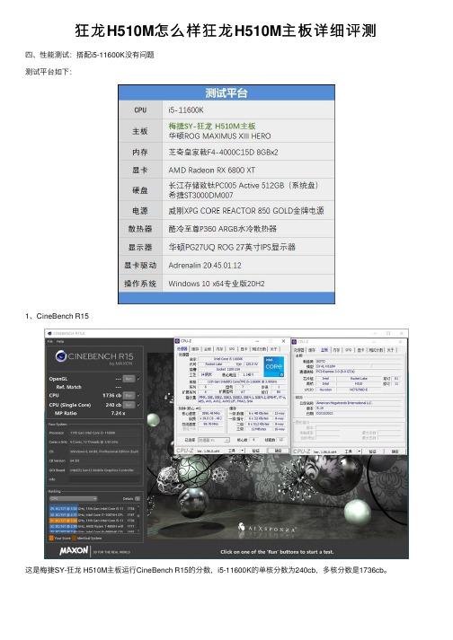
与华硕ROG MAXIMUS XIII HERO主板相比,梅捷SY-狂龙H510M的单线程分数差异是2%,多线程差距是1%。 要知道M13H主板是在Gear 1 3600MHz内存模式下运行,而狂龙H510M仅仅只是Gear 2 3200MHz。 2、FritzChess Benchmark
国际象棋的测试,狂龙H510M主板与ROG M13H的差距依然只有1%。 上一页 1 2 3 45 下一页 阅读全文
主板作为电脑装机中最为关键的一环很多用户都想知道各个型号的主板性能发挥如何这里小编为大家带来主板天梯图2021最新版主板排名天梯图一般是根据主板供电性能来排名
狂龙 H510M怎么样狂龙 H510M主板详细评测
四、性能测试:R15
这是梅捷SY-狂龙 H510M主板运行CineBench R15的分数,i5-11600K的单核分数为240cb,多核分数是1736cb。
梅捷主板说明书

The information in this document is subject to change without notice and does not represent a commitment on part of the vendor, who assumes no liability or responsibility for any errors that may appear in this manual.
2. BIOS Setup....................................................................... 2-1
3. Driver & Utility ................................................................. 3-1
5. Appendix .......................................................................... 5-1 5.1 Troubleshooting (How to Get Technical Support?) ..........................5-1 5.1.1 Q & A .................................................................................5-1 5.1.2 Technical Support Form ......................................................5-4 5.1.3 Contact Information ............................................................5-5
梅捷AMD系列主板说明书

梅捷AMD系列主板说明书适用于:AMD系列芯片组说明书版本V1.7更新日期2014年5月30日梅捷简体中文网站/梅捷中国大陆技术支持E-mail:梅捷官方微博/soyo1999梅捷中国大陆服务电话************版权声明:说明书版权归梅捷科技所有。
梅捷科技有权在不知会用户的前提下增益、删除内容。
本说明书为纯技术文档,无任何暗示及映射第三方内容。
且不承担因印刷及排版错误而导致的任何歧义。
本说明书中所涉及之任何第三方之注册商标,所有权归其制造商或品牌供应商所有。
Copyright©1999——2014版权所有、未经授权,禁止以任何方式复制传播。
关于本手册:本说明书适合初学者,包含相关产品特性介绍及软体安装介绍,以及一些名词的解释。
本说明书可以作为技术性参考资料,用户使用时请以实物为准。
非正常保修范围:1、产品因不当使用与安装,自行拆解或更换零件,或是任意变更规格所造成的故障与损坏,不在保修范围内。
2、产品一经变更或修改,以及任何因间接、特殊或意外情况所造成的损害,不在保修范围内。
避免在下列环境中使用本产品:高温、低气压、低温、潮湿、多尘、磁场强大及长期暴露于阳光之下。
本公司建议您在海拔3000米以下,0°至35°C,湿度为5%至95%的环境中使用。
FCC条款:本装置完全遵循FCC条款第15部分的规定。
遵照下列两项条件来作业:1、本装置不会造成人身伤害;2、本装置必须能接受任何已回复的冲突干扰,包括可能会造成不当操作的冲突。
注意:依照FCC条款第15部分规定,本装置已经通过测试并且符合Class B数位装置的限制。
这项限制是为了安装过程中可能造成的伤害性冲突的合理防范措施。
本装置产生、使用、并且可以发射无线电的频率能量,但如果没有依照制造商的指示安装和使用,可能会与通讯工具造成伤害性冲突。
然而,并不保证在特定的安装下不会产生任何冲突。
如果关闭和重开本装置后,仍确定本装置真的造成收音机或电视机的冲突,请使用者利用下列一项或多项知识来更正所造成的冲突:●重新安装接收天线;●增加装置与受讯器间的分隔;●将电脑插入不同的插座以便于两个装置使用不同的回路。
电脑主板类型详解及主板跳线接法大全

华硕ASUS(成立于1990年,世界财富500强企业,全球领先的3C 解决方案提供商之一,上市公司,华硕电脑股份有限公司) 技嘉GIGABYTE(成立于1986年,十大主板品牌,全球顶尖主板、显卡和硬体解决方案制造商之一,宁波技嘉国际贸易有限公司)微星msi(于1986年,全球第一大显示卡生产商,全球最大的主机板制造商之一,行业领先品牌,微优商贸(深圳)有限公司)映泰BIOSTAR(始于1986年,专业致力于计算机行业硬件主板产品研发生产的企业,十大主板品牌,深圳市映泰科技有限公司)精英ECS(于1987年,致力于计算机产品设计/制造的著名厂商,行业著名品牌,十大主板品牌,精英电脑股份有限公司)华擎ASRock(创立于台湾,专注于高品质主板的专业企业,上市公司,知名准系统品牌,行业领先品牌,华擎科技股份有限公司) 七彩虹Colorful(于1995年,致力于IT 渠道增值业务,著名品牌,显卡行业领军品牌,深圳市七彩虹科技发展有限公司)昂达ONDA(中国市场最大和最具影响力的品牌之一,国内最具影响力的PC 配件及数码产品提供商,广州昂达电子有限公司) 梅捷SOYO(始建于1985台湾,十大主板品牌,全球知名主板品牌,行业技术领先企业,商科集团运营,梅捷企业股份有限公司) 10 富士康Foxconn(于1974年,专业从事电脑、通讯、消费电子、汽车零组件、通路等6C 产业的高新科技企业,富士康科技集团)华硕,技嘉,微星,映泰,精英,华擎,七彩虹,昂达,梅捷,富士康华硕,技嘉,微星,映泰,精英,华擎,七彩虹,昂达,梅捷,富士康神舟(hasee)宏碁(Acer)海尔(hair)联想(Lenovo)戴尔(dell)惠普(HP)松下(panasonic)东芝(Toshiba)华硕(ASUS)从第二张图片所示裸露的显卡上,我们可以看到有8颗黑色的芯片,它们就是显卡的显存,相当于电脑系统中内存的作用,当主芯片一定的情况下,显卡的性能高低就由显存来决定了。
这也就是大名鼎鼎的图拉丁核心

Tualatin这也就是大名鼎鼎的“图拉丁”核心,是Intel在Socket 370架构上的最后一种CPU核心,采用0.13um制造工艺,封装方式采用FC-PGA2和PPGA,核心电压也降低到了1.5V左右,主频范围从1GHz到1.4GHz,外频分别为100MHz(赛扬)和133MHz(Pentium III),二级缓存分别为512KB(Pentium III-S)和256KB(Pentium III和赛扬),这是最强的Socket 370核心,其性能甚至超过了早期低频的Pentium 4系列CPU。
Willamette这是早期的Pentium 4和P4赛扬采用的核心,最初采用Socket 423接口,后来改用Socket 478接口(赛扬只有1.7GHz和1.8GHz两种,都是Socket 478接口),采用0.18um制造工艺,前端总线频率为400MHz,主频范围从1.3GHz到2.0GHz(Socket 423)和1.6GHz到2.0GHz(Socket 478),二级缓存分别为256KB(Pentium 4)和128KB(赛扬),注意,另外还有些型号的Socket 423接口的Pentium 4居然没有二级缓存!核心电压1.75V左右,封装方式采用Socket 423的PPGA INT2,PPGA INT3,OOI 423-pin,PPGA FC-PGA2和Socket 478的PPGA FC-PGA2以及赛扬采用的PPGA等等。
Willamette核心制造工艺落后,发热量大,性能低下,已经被淘汰掉,而被Northwood核心所取代。
Northwood这是目前主流的Pentium 4和赛扬所采用的核心,其与Willamette核心最大的改进是采用了0.13um制造工艺,并都采用Socket 478接口,核心电压1.5V左右,二级缓存分别为128KB(赛扬)和512KB(Pentium 4),前端总线频率分别为400/533/800MHz(赛扬都只有400MHz),主频范围分别为2.0GHz到2.8GHz(赛扬),1.6GHz到2.6GHz(400MHz FSB Pentium 4),2.26GHz到3.06GHz(533MHz FSB Pentium 4)和2.4GHz到3.4GHz(800MHz FSB Pentium 4),并且3.06GHz Pentium 4和所有的800MHz Pentium 4都支持超线程技术(Hyper-Threading Technology),封装方式采用PPGA FC-PGA2和PPGA。
MSI B550M-A PRO A520M-A PRO主板说明书
1ContentsContentsSafety Information ...........................................................................................2Specifications ...................................................................................................3Rear I/O Panel .................................................................................................6LAN Port LED Status Table . (6)Overview of Components (7)CPU Socket .................................................................................................................8DIMM Slots..................................................................................................................9PCI_E1~2: PCIe Expansion Slots ................................................................................9M2_1: M.2 Slot ..........................................................................................................10SATA1~4: SATA 6Gb/s Connectors ...........................................................................10JFP1, JFP2: Front Panel Connectors .......................................................................11JAUD1: Front Audio Connector ................................................................................11ATX_PWR1, CPU_PWR1: Power Connectors ...........................................................12JUSB1, JUSB2: USB 2.0 Connectors ........................................................................13JUSB3: USB 3.2 Gen1 Connector .............................................................................13CPU_FAN1, SYS_FAN1: Fan Connectors .................................................................14JTPM1: TPM Module Connector ...............................................................................14JCI1: Chassis Intrusion Connector ...........................................................................15JCOM1: Serial Port Connector .................................................................................15JBAT1: Clear CMOS (Reset BIOS) Jumper ...............................................................16EZ Debug LED ...........................................................................................................16UEFI BIOS . (17)BIOS Setup ................................................................................................................18Entering BIOS Setup .................................................................................................18Resetting BIOS ..........................................................................................................18Updating BIOS...........................................................................................................19Installing OS, Drivers & Utilities . (20)Installing Windows® 10 .............................................................................................20Installing Drivers ......................................................................................................20Installing Utilities .....................................................................................................20Thank you for purchasing the MSI® B550M-A PRO/ A520M-A PRO motherboard. This User Guide gives information about board layout, component overview, BIOS setup and software installation.Safety Information∙The components included in this package are prone to damage from electrostatic discharge (ESD). Please adhere to the following instructions to ensure successful computer assembly.∙Ensure that all components are securely connected. Loose connections may cause the computer to not recognize a component or fail to start.∙Hold the motherboard by the edges to avoid touching sensitive components. ∙It is recommended to wear an electrostatic discharge (ESD) wrist strap when handling the motherboard to prevent electrostatic damage. If an ESD wrist strap is not available, discharge yourself of static electricity by touching another metal object before handling the motherboard.∙Store the motherboard in an electrostatic shielding container or on an anti-static pad whenever the motherboard is not installed.∙Before turning on the computer, ensure that there are no loose screws or metal components on the motherboard or anywhere within the computer case.∙Do not boot the computer before installation is completed. This could cause permanent damage to the components as well as injury to the user.∙If you need help during any installation step, please consult a certified computer technician.∙Always turn off the power supply and unplug the power cord from the power outlet before installing or removing any computer component.∙Keep this user guide for future reference.∙Keep this motherboard away from humidity.∙Make sure that your electrical outlet provides the same voltage as is indicated on the PSU, before connecting the PSU to the electrical outlet.∙Place the power cord such a way that people can not step on it. Do not place anything over the power cord.∙All cautions and warnings on the motherboard should be noted.∙If any of the following situations arises, get the motherboard checked by service personnel:▪Liquid has penetrated into the computer.▪The motherboard has been exposed to moisture.▪The motherboard does not work well or you can not get it work according touser guide.▪The motherboard has been dropped and damaged.▪The motherboard has obvious sign of breakage.∙Do not leave this motherboard in an environment above 60°C (140°F), it may damage the motherboard.2Safety Information3Specifications4SpecificationsNorton™ Internet Security SolutionPlease refer to http:///manual/mb/DRAGONCENTER2.pdf formore details.5SpecificationsAudio 7.1-channel ConfigurationTo configure 7.1-channel audio, you have to connect front audio I/O module to JAUD1 connector and follow the below steps.1. Click on the Realtek HD Audio Manager > Advanced Settings to open the dialogbelow.2. Select Mute the rear output device, when a front headphone plugged in.3. Plug your speakers to audio jacks on rear and front I/O panel. When you plug intoa device at an audio jack, a dialogue window will pop up asking you which deviceis current connected.6Rear I/O Panel7Overview of ComponentsOverview of Components* Distance from the center of the CPU to the nearest DIMM slot.M2_1JTPM1PCI_E1PCI_E2Important∙Always unplug the power cord from the power outlet before installing or removing the CPU.∙Please retain the CPU protective cap after installing the processor. MSI will deal with Return Merchandise Authorization (RMA) requests if only the motherboard comes with the protective cap on the CPU socket.∙When installing a CPU, always remember to install a CPU heatsink. A CPU heatsink is necessary to prevent overheating and maintain system stability.∙Confirm that the CPU heatsink has formed a tight seal with the CPU before booting your system.∙Overheating can seriously damage the CPU and motherboard. Always make sure the cooling fans work properly to protect the CPU from overheating. Be sure to apply an even layer of thermal paste (or thermal tape) between the CPU and the heatsink to enhance heat dissipation.∙If you purchased a separate CPU and heatsink/ cooler, Please refer to the docu-mentation in the heatsink/ cooler package for more details about installation.8Overview of Componentscard’s documentation to check for any necessary additional hardware or softwarechanges.9Overview of ComponentsSATA1~4: SATA 6Gb/s ConnectorsThese connectors are SATA 6Gb/s interface ports. Each connector can connect to one SATA device.⚠Important∙Please do not fold the SATA cable at a 90-degree angle. Data loss may result during transmission otherwise.∙SATA cables have identical plugs on either sides of the cable. However, it is recommended that the flat connector be connected to the motherboard for space saving purposes.M2_1: M.2 SlotPlease install the M.2 device into the M.2 slot as shown below.13StandoffSupplied10Overview of ComponentsJFP1, JFP2: Front Panel ConnectorsJAUD1: Front Audio Connector11Overview of ComponentsATX_PWR1, CPU_PWR1: Power ConnectorsImportantMake sure that all the power cables are securely connected to a proper ATX power supply to ensure stable operation of the motherboard.12Overview of Components13Overview of ComponentsJUSB3: USB 3.2 Gen1 ConnectorImportantNote that the Power and Ground pins must be connected correctly to avoid possible damage.JUSB1, JUSB2: USB 2.0 Connectors∙Note that the VCC and Ground pins must be connected correctly to avoid possible damage.∙In order to recharge your iPad,iPhone and iPod through USB ports, please install MSI® SUPER CHARGER software.14Overview of ComponentsImportantYou can adjust fan speed in BIOS > Hardware Monitor.CPU_FAN1, SYS_FAN1: Fan ConnectorsPWM Mode fan connectors provide constant 12V output and adjust fan speed with speed control signal. When you plug a 3-pin (Non-PWM) fan to a fan connector in PWM mode, the fan speed will always maintain at 100%, which might create a lot ofnoise.JTPM1: TPM Module ConnectorThis connector is for TPM (Trusted Platform Module). Please refer to the TPMJCI1: Chassis Intrusion Connector(default)intrusion eventUsing chassis intrusion detector1. Connect the JCI1 connector to the chassis intrusion switch/ sensor on the chassis.2. Close the chassis cover.3. Go to BIOS > SETTINGS > Security > Chassis Intrusion Configuration.4. Set Chassis Intrusion to Enabled.5. Press F10 to save and exit and then press the Enter key to select Yes.6. Once the chassis cover is opened again, a warning message will be displayed on screen when the computer is turned on.Resetting the chassis intrusion warning1. Go to BIOS > SETTINGS > Security > Chassis Intrusion Configuration.2. Set Chassis Intrusion to Reset.3. Press F10 to save and exit and then press the Enter key to select Yes. JCOM1: Serial Port Connector15Overview of ComponentsJBAT1: Clear CMOS (Reset BIOS) JumperThere is CMOS memory onboard that is external powered from a battery located on the motherboard to save system configuration data. If you want to clear the system(default)BIOSResetting BIOS to default values1. Power off the computer and unplug the power cord.2. Use a jumper cap to short JBAT1 for about 5-10 seconds.3. Remove the jumper cap from JBAT1.4. Plug the power cord and power on the computer.EZ Debug LEDThese LEDs indicate the status of the motherboard.CPU - indicates CPU is not detected or fail.DRAM - indicates DRAM is not detected or fail.VGA - indicates GPU is not detected or fail.BOOT - indicates booting device is not detected or fail.16Overview of ComponentsUEFI BIOSMSI UEFI BIOS is compatible with UEFI (Unified Extensible Firmware Interface) architecture. UEFI has many new functions and advantages that traditional BIOS cannot achieve, and it will completely replace BIOS in the future. The MSI UEFI BIOS uses UEFI as the default boot mode to take full advantage of the new chipset’s capabilities. However, it still has a CSM (Compatibility Support Module) mode to be compatible with older devices. That allows you to replace legacy devices with UEFI compatible devices during the transition.⚠ImportantThe term BIOS in this user guide refers to UEFI BIOS unless otherwise noted. UEFI advantages∙Fast booting - UEFI can directly boot the operating system and save the BIOS self-test process. And also eliminates the time to switch to CSM mode during POST.∙Supports for hard drive partitions larger than 2 TB.∙Supports more than 4 primary partitions with a GUID Partition Table (GPT).∙Supports unlimited number of partitions.∙Supports full capabilities of new devices - new devices may not provide backward compatibility.∙Supports secure startup - UEFI can check the validity of the operating system to ensure that no malware tampers with the startup process.Incompatible UEFI cases∙32-bit Windows operating system - this motherboard supports only 64-bit Windows 10 operating system.∙Older graphics card - the system will detect your graphics card. When display a warning message There is no GOP (Graphics Output protocol) support detected in this graphics card.⚠ImportantWe recommend that you to use a GOP/ UEFI compatible graphics card.How to check the BIOS mode?17UEFI BIOSBIOS SetupThe default settings offer the optimal performance for system stability in normal conditions. You should always keep the default settings to avoid possible system damage or failure booting unless you are familiar with BIOS.⚠Important∙BIOS items are continuous update for better system performance. Therefore, the description may be slightly different from the latest BIOS and should be held for reference only. You could also refer to the HELP information panel for BIOS item description.∙The BIOS items will vary with the processor. Entering BIOS SetupPress Delete key, when the Press DEL key to enter Setup Menu, F11 to enter Boot Menu message appears on the screen during the boot process.Function keyF1: General HelpF2: Add/ Remove a favorite itemF3: Enter Favorites menuF4: Enter CPU Specifications menuF5: Enter Memory-Z menuF6: Load optimized defaultsF7: Switch between Advanced mode and EZ modeF8: Load Overclocking ProfileF9: Save Overclocking ProfileF10: Save Change and Reset*F12: Take a screenshot and save it to USB flash drive (FAT/ FAT32 format only). Ctrl+F: Enter Search page* When you press F10, a confirmation window appears and it provides the modification information. Select between Yes or No to confirm your choice. Resetting BIOSYou might need to restore the default BIOS setting to solve certain problems. There are several ways to reset BIOS:∙Go to BIOS and press F6 to load optimized defaults.∙Short the Clear CMOS jumper on the motherboard.⚠ImportantPlease refer to the Clear CMOS jumper section for resetting BIOS.18UEFI BIOSUpdating BIOSUpdating BIOS with M-FLASHBefore updating:Please download the latest BIOS file that matches your motherboard model from MSI website. And then save the BIOS file into the USB flash drive.Updating BIOS:1. Insert the USB flash drive that contains the update file into the USB port.2. Please refer the following methods to enter flash mode.▪Reboot and press Ctrl + F5 key during POST and click on Yes to reboot the system.▪Reboot and press Del key during POST to enter BIOS. Click the M-FLASH button and click on Yes to reboot the system.3. Select a BIOS file to perform the BIOS update process.4. When prompted click on Yes to start recovering BIOS.5. After the flashing process is 100% completed, the system will reboot automatically.Updating the BIOS with Dragon CenterBefore updating:Make sure the LAN driver is already installed and the internet connection is set properly.Updating BIOS:1. Install and launch MSI DRAGON CENTER and go to Support page.2. Select Live Update and click on Advance button.3. Click on Scan button to search the latest BIOS file.4. Select the BIOS file and click on Download icon to download and install the latest BIOS file.5. Click Next and choose In Windows mode. And then click Next and Start to start updating BIOS.6. After the flashing process is 100% completed, the system will restart automatically.19UEFI BIOSInstalling OS, Drivers & UtilitiesPlease download and update the latest utilities and drivers at Installing Windows® 101. Power on the computer.2. Insert the Windows® 10 installation disc/USB into your computer.3. Press the Restart button on the computer case.4. Press F11 key during the computer POST (Power-On Self Test) to get into BootMenu.5. Select the Windows® 10 installation disc/USB from the Boot Menu.6. Press any key when screen shows Press any key to boot from CD or DVD...message.7. Follow the instructions on the screen to install Windows® 10. Installing Drivers1. Start up your computer in Windows® 10.2. Insert MSI® Driver Disc into your optical drive.3. Click the Select to choose what happens with this disc pop-up notification,then select Run DVDSetup.exe to open the installer. If you turn off the AutoPlayfeature from the Windows Control Panel, you can still manually execute theDVDSetup.exe from the root path of the MSI Driver Disc.4. The installer will find and list all necessary drivers in the Drivers/Software tab.5. Click the Install button in the lower-right corner of the window.6. The drivers installation will then be in progress, after it has finished it will promptyou to restart.7. Click OK button to finish.8. Restart your computer.Installing UtilitiesBefore you install utilities, you must complete drivers installation.1. Open the installer as described above.2. Click the Utilities tab.3. Select the utilities you want to install.4. Click the Install button in the lower-right corner of the window.5. The utilities installation will then be in progress, after it has finished it willprompt you to restart.6. Click OK button to finish.7. Restart your computer.20Installing OS, Drivers & Utilities。
梅捷SY-ZEUS Z370 eSport说明书.pdf
梅捷Intel Z370系列主板说明书适用于:SY-ZEUS Z370 eSportVersion 1.02017年9月30日7产品中有害物质的名称及含量本表格依据 SJ/T 11364 的规定编制。
○:表示该有害物质在该部件所有均质材料中的含量均在 GB/T 26572 规定的限量要求以下。
×:表示该有害物质至少在该部件的某一均质材料中的含量超出 GB/T 26572 规定的限量要求。
第一章 硬件安装........................................................................................................................................... - 5 - 1.1 处理器的安装............................................................................................................................. - 6 - 1.2 安装 CPU 风扇........................................................................................................................... - 7 - 1.3 系统内存安装............................................................................................................................. - 8 - 1.3.2 内存设置...................................................................................................................... - 9 - 1.4 SATA 设备安装.........................................................................................................................- 10 - 1.5 M.2(NGFF)设备安装..........................................................................................................- 11 - 1.6 其他插座(插针)安装............................................................................................................- 12 - 1.6.1 前置USB_3.0/2.0插座连接.....................................................................................- 12 - 1.6.2 F_PANEL、SPEAKER插座连接..............................................................................- 13 - 1.6.3 F_AUDIO插座安装...................................................................................................- 13 - 1.6.4 LED_C外接灯带插座安装........................................................................................- 14 - 1.6.5 ATX 电源插座安装....................................................................................................- 15 - 1.7 PCI-E 设备安装.........................................................................................................................- 16 - 1.7.1 PCI-E 设备安装.........................................................................................................- 16 - 1.7.2 PCI-E 多显卡安装.....................................................................................................- 17 -第二章 软件安装及设置..............................................................................................................................- 18 - 2.1 主板驱动程序安装....................................................................................................................- 18 - 2.2 多声道输出设置方法................................................................................................................- 18 -第三章 BIOS 设定........................................................................................................................................- 19 - 3.1 EFI BIOS 说明...........................................................................................................................- 19 - 3.2 Main(系统设定界面)..........................................................................................................- 19 - 3.3 Advanced (高级设置界面).............................................................................................. - 21 - 3.3.1 Trusted Computing(TPM2.0)........................................................................- 22 - 3.3.2 ACPI Settings (ACPI配置)...............................................................................- 22 - 3.3.3 SATA Configuration (SATA配置)...................................................................- 23 - 3.3.4 Super IO Configuration(超级输入/输出配置)............................................- 23 - 3.3.5 H/W Monitor (系统状态监控)........................................................................- 24 - 3.3.6 Power Management Configuration(电源管理配置)...............................- 24 - 3.3.7 CPU Configuration(USB配置)........................................................................- 25 - 3.3.8 No Disk(PXE) (无盘支持设置界面).................................................................- 25 - 3.3.9 CSM Configuration(CSM配置)......................................................................- 26 - 3.3.10 USB Configuration(USB配置).....................................................................- 26 -3.4 Chipset (芯片组功能设定)................................................................................................- 27 - 3.5 Turbo (系统加速功能设定)...............................................................................................- 27 - 3.6 Security(安全特性)............................................................................................................- 29 - 3.7 Startup (启动功能设定)....................................................................................................- 30 - 3.8 Save & Exit (保存与退出)................................................................................................- 31 -第四章 附录..................................................................................................................................................- 32 -4.1 Debug代码说明.......................................................................................................................- 32 - 4.2 故障排除....................................................................................................................................- 34 - 4.3 板载按键说明............................................................................................................................- 36 -品质保证卡....................................................................................................................................................- 40 -第一章 硬件安装6.对Windows系统的支持(Win10_64bit)PC 所需的其他工具与元件· 上表所列的工具与元件并不包含在主板包装盒内。
- 1、下载文档前请自行甄别文档内容的完整性,平台不提供额外的编辑、内容补充、找答案等附加服务。
- 2、"仅部分预览"的文档,不可在线预览部分如存在完整性等问题,可反馈申请退款(可完整预览的文档不适用该条件!)。
- 3、如文档侵犯您的权益,请联系客服反馈,我们会尽快为您处理(人工客服工作时间:9:00-18:30)。
豪华全固态电容 支持DDR2/DDR3内存 支持 内存 千兆网卡 带DIY按键 按键
L.P.U.极致冷技P.U极致冷技 极致冷技 术可让主板更高效地 散发热量, 散发热量,从而有效 降低主板以及机箱内 部的温度, 部的温度,让整机系 统始终保持在最稳定 的工作状态, 的工作状态,避免主 板因为过热导致重启 死机等问题的出现, 死机等问题的出现, 家庭用户及 为家庭用户及网吧用 提供可靠、 户提供可靠、安心的 使用环境。 使用环境。
超导热焊触点
L.P.U极致冷技术除了在主板 极致冷技术除了在主板PCB 极致冷技术除了在主板 内部注入99.999%纯铜内层外,整片 纯铜内层外, 内部注入 纯铜内层外 主板还采用上超导热焊触点 超导热焊触点, 主板还采用上超导热焊触点,经过高 纯度提炼焊点的导热性比传统焊点高 出两倍,比传统主板温度降低 温度降低2℃ 出两倍,比传统主板温度降低 ℃。 主板上的元器件都是经过机器或 者人工焊接,经过焊接后会在PCB背 者人工焊接,经过焊接后会在 背 面留下相应的焊点, 面留下相应的焊点,焊点连接着元器 件的插脚,连通PCB内层及走线。所 内层及走线。 件的插脚,连通 内层及走线 以采用高纯度提炼的焊点, 以采用高纯度提炼的焊点,导热系数 大大增加,能够迅速带走主板的热量。 大大增加,能够迅速带走主板的热量。
梅捷独家首创L.P.U.极致冷技术 极致冷技术 梅捷独家首创
梅捷独家首创L.P.U.极致冷技术 极致冷技术 梅捷独家首创
•
在主板行业日益同质化的时代, 在主板行业日益同质化的时代,梅捷仍以保 持以质量技术至上的产品设计理念, 持以质量技术至上的产品设计理念,继推出引领 网吧管理的网易通II技术后 技术后, 网吧管理的网易通 技术后,梅捷主板在技术上 再次作出突破, 年独家首创L.P.U极致冷 再次作出突破,在2009年独家首创 年独家首创 极致冷 技术。 技术。这是经过梅捷专业开发团队长时间深入研 发的成果, L.P.U极致冷技术是业界首创的主板 发的成果, 极致冷技术是业界首创的主板 散热技术,具有L.P.U智能冷控技术的主板,能 智能冷控技术的主板, 散热技术,具有 智能冷控技术的主板 比传统主板温度降低 温度降低5-8℃ 比传统主板温度降低 ℃,在行业内属于领先定 位。
梅捷L.P.U极致冷系统原理 极致冷系统原理 梅捷
L.P.U技术使主板温度低 ℃ 技术使主板温度低5-8℃ 技术使主板温度低
内置有L.P.U技术) 技术) (目前仅梅捷SY-P45+内置有 目前仅梅捷 内置有 技术
从前面的L.P.U.极致冷技术原理图可以看到: 极致冷技术原理图可以看到: 从前面的 极致冷技术原理图可以看到 一体化热管系统、 纯铜PCB内层、超导 内层、 一体化热管系统、99.999%纯铜 纯铜 内层 热焊触点,经过三者的完美结合,使得梅捷P45+ 热焊触点,经过三者的完美结合,使得梅捷 有着高散热效能。根据实际的测试数据, 有着高散热效能。根据实际的测试数据,具备 L.P.U极致冷技术的梅捷 极致冷技术的梅捷P45+相比起传统主板温度 相比起传统主板温度 极致冷技术的梅捷 相比起传统主板 要低5-8℃ 要低 ℃。
什么是L.P.U.极致冷技术? 极致冷技术? 什么是 极致冷技术
L.P.U极致冷技术由三部分组成: 极致冷技术由三部分组成: 极致冷技术由三部分组成 1. 一体化热管系统 2. 99.999%纯铜 纯铜PCB内层 纯铜 内层 3. 超导热焊触点 4. 超导热焊触点
一体化热管系统
一体化热管系统是针对 一体化热管系统是针对CPU供电 是针对 供电 模组和芯片组元器件散热。 模组和芯片组元器件散热。凡具有 L.P.U极致冷技术的梅捷主板,则会在 极致冷技术的梅捷主板, 极致冷技术的梅捷主板 主板上安装一体化热管散热系统, 主板上安装一体化热管散热系统,连 供电模组的MOSFET及芯片组, 及芯片组, 接CPU供电模组的 供电模组的 及芯片组 其热量均恒系统比传统主板温度降低 其热量均恒系统比传统主板温度降低 3℃。 ℃ 热管散热充分利用了热传导原理与 致冷介质的快速热传递性质, 致冷介质的快速热传递性质,透过热 管将发热物体的热量迅速传递到热源 外,其导热能力超过了任何已知金属 的导热能力。 的导热能力。而且还解决了风冷散热 带来的噪音问题。 带来的噪音问题。
网易通II技术、 网易通 技术、L.P.U极致冷技术 技术 极致冷技术 两把网吧做单利剑
梅捷P45+除具备全固态电容、支持DDR3、 梅捷P45+除具备全固态电容、支持DDR3、带 除具备全固态电容 自恢复保险丝、带防雷防静电保护IC等固有卖点外 等固有卖点外, 自恢复保险丝、带防雷防静电保护 等固有卖点外, 还具备有网易通 网易通II、 极致冷两大技术优势。 还具备有网易通 、L.P.U极致冷两大技术优势。我 极致冷两大技术优势 们可充分利用梅捷P45+两大差异化优势开拓做单 们可充分利用梅捷 两大差异化优势开拓做单 市场,抢占更多网吧市场份额!!! 市场,抢占更多网吧市场份额!!!
梅捷SY-P45+率先引入 率先引入L.P.U.极致冷技术 梅捷 率先引入 极致冷技术
梅捷SY-P45+参数卖点: 参数卖点: 梅捷 参数卖点 ATX大板 大板 梅捷独家L.P.U.极致冷技术 梅捷独家 极致冷技术 Intel P45+ICH10芯片组 芯片组 支持酷睿2系列处理器 支持酷睿 系列处理器 采用高端R80电感 采用高端 电感
99.999%纯铜 纯铜PCB内层 纯铜 内层
L.P.U极致冷技术在主板上采用 极致冷技术在主板上采用99.999% 极致冷技术在主板上采用 纯铜电路屈设计 电路屈设计, 纯铜电路屈设计,原理即是在印刷电路板中 注入99.999%纯铜内层,导热系数达到 纯铜内层, 注入 纯铜内层 386W(MK),比传统主板温度降低 ℃。 ),比传统主板温度降低3℃ ( ),比传统主板温度降低 经过优化的PCB设计,不仅能节约成本, 设计, 经过优化的 设计 不仅能节约成本, 还能降低发热量。而梅捷科技率先在PCB注 还能降低发热量。而梅捷科技率先在 注 纯铜内层, 入99.999%纯铜内层,不仅能从根本降低主 纯铜内层 板发热量,还能达到良好的电路性能, 板发热量,还能达到良好的电路性能,使得 主板性能更加稳定。 主板性能更加稳定。
