M2 U2 Shangrila (2)
智能电源说明书

TAA SmartPro 120V 3kVA 2.88kW Line-Interactive Sine Wave UPS, 2U, Extended Run, Network Card Options, LCD, USB, DB9MODEL NUMBER:SM3000RMXL2UTAADescriptionSmartPro® Line-Interactive UPS with enhanced LCD interface offers network-grade power protection for critical server, network and telecommunications equipment. Line-Interactive Uninterruptible Power Supply (UPS) with built-in Auto-Voltage Regulation (AVR) actively corrects brownouts and overvoltages back to usable levels while maintaining a full battery charge in case of power failure. This unique configuration excels in exceptionally poor power environments with two separate levels of voltage boost to correct both slight undervoltages and severe brownout conditions. Interactive LCD/LED interface reports UPS operating mode, detailed UPS and site-power data, plus enables a variety of UPS setup and configuration options. Super-fast switchover from line to battery power occurs within milliseconds to maintain operation of connected equipment without interruption or reboot. 96-percent line-mode efficiency offers reduced heat emissions and operating costs. Network management interfaces support communications via USB, RS-232 and optional slot for network management card options. HID-compliant USB interface enables integration with built-in power management and auto shutdown features of Windows and macOS. Network communications ports enable detailed monitoring of equipment load levels, self-test data and utility power conditions. PowerAlert® UPS monitoring and auto shutdown software is available via free download. Switched output load banks enable scheduled and real-time remote reboot and load shedding of select outlets. Emergency Power Off (EPO) interface. LED/LCD display panel easily rotates for viewing in rack-mount or tower configurations. Audible alarm with push-button momentary alarm-cancel and silent-mode configuration options. Programmable self-test. Field-replaceable, hot-swappable battery modules.FeaturesCompliant with the Federal Trade Agreements Act (TAA) for GSA Schedule purchasesqSM3000RMXL2UTAA line interactive 2U rack/tower UPS with 3000VA / 3kVA capacity and extended runtime optionsqLine interactive UPS with Automatic Voltage Regulation (AVR) corrects brownouts and overvoltages from 83 to 145VqNEMA L5-30P input plug; 8 NEMA 5-15/20R and 1 L5-30R output receptacles, Two independently switchable output load banksqMaintains uninterrupted operation of connected networking equipment during blackouts, surges, brownouts and overvoltagesqHigh 96% efficiency rating in line-power mode offers reduced power consumption and BTU emisssions qInternal batteries offer 10 minutes at 50% load (1440W) and 3 minutes at 100% load (2880W)q Highlights3kVA / 3000VA / 2880W lineinteractive 2U rack/tower UPS,Sine WaveqExtended runtime options up to2880W, 0.9 Power Factor,Interactive LCD interfaceqUSB, RS232, EPO and slot fornetwork management cardoptionsqNEMA L5-30P input; 8 NEMA 5-15/20R & 1 L5-30R outletsqTAA Compliant for GSASchedule purchasesqTo use the Auto Probe feature,this product requires aWEBCARDLXE networkinterface (sold separately)running LX firmware update20.2 or laterqPackage IncludesSM3000RMXL2UTAA UPSsystemqPowerAlert Software with USB,Serial & EPO cablingq4 post rackmount installation kit qInstruction manualqSpecificationsExtended runtime is available with optional BP48V24-2U / BP48V242UTAA (limit 1) OR BP48V60RT3U / BP48V60RT3UTAA (no limit)qExternal battery configurations require the use of External Battery Configuration Software (see manual)q Hot-swappable, user-replaceable internal batteries and external battery packs can be replaced with no disruption to connected equipmentqFollowing an extended power outage, the UPS will automatically restart into line-power mode, begin powering connected equipment and recharge the battery system, all without user interactionqFront panel LCD monitoring screen with MODE and ENTER buttons reports operating mode with 5-bar battery charge graphic, plus 7 selectable screens of detailed UPS and site power information qLCD interface also supports a number of advanced user setup and operating preferencesq Ships with 4-post rack-mount installation hardware; Optional 2POSTRMKITWM enables 2-post rack-mount/wallmount installation; Optional 2-9USTAND enables tower placementqBuilt-in USB, RS-232 and optional slot for network management card options; Compatible with UPS management card options TLNETCARD and WEBCARDLXEqHID-compliant USB interface enables integration with built-in power management and auto shutdown features of Windows and macOSqUSB & Serial ports enable data-saving unattended shutdown when used with PowerAlert software,available via FREE download from /products/power-alert qBuilt-in Emergency Power Off (EPO) interface with cableq© 2023 Eaton. All Rights Reserved. Eaton is a registered trademark. All other trademarks are the property of their respective owners.。
ESP32-S2-MINI-2 2.4G WiFi模组技术规格书说明书

P RE LI MI N A R YESP32S2MINI2ESP32S2MINI2U技术规格书2.4GHz WiFi (802.11b/g/n)模组内置ESP32S2系列芯片(版本v1.0),Xtensa ®单核32位LX7微处理器内置芯片叠封4MB flash ,可叠封2MB PSRAM 37个GPIO ,丰富的外设板载PCB 天线或外部天线连接器ESP32S2MINI2ESP32S2MINI2U预发布v0.5乐鑫信息科技版权©2022P RE LI MI N A R1模组概述1.1特性CPU 和片上存储器•内置ESP32-S2FH4或ESP32-S2FN4R2芯片,Xtensa ®单核32位LX7微处理器,支持高达240MHz 的时钟频率•128KB ROM •320KB SRAM •16KB RTC SRAM •4MB flash•2MB PSRAM (仅ESP32-S2FN4R2芯片)WiFi•802.11b/g/n•802.11n 模式下数据速率高达150Mbps •帧聚合(TX/RX A-MPDU,RX A-MSDU)•0.4µs 保护间隔•工作信道中心频率范围:2412~2484MHz外设•GPIO 、SPI 、UART 、I2C 、I2S 、LCD 接口、Camera 接口、IR 、脉冲计数器、LED PWM 、TWAI ®(兼容ISO 11898-1,即CAN 规范2.0)、全速USB OTG 、ADC 、DAC 、触摸传感器、温度传感器、通用定时器、看门狗定时器模组集成元件•40MHz 集成晶振天线选型•板载PCB 天线(ESP32-S2-MINI-2)•通过连接器连接外部天线(ESP32-S2-MINI-2U)工作条件•工作电压/供电电压:3.0~3.6V •工作环境温度:–85°C 版模组:–40~85°C–105°C 版模组:-40~105°C (仅ESP32-S2-MINI-2-H4和ESP32-S2-MINI-2U-H4)1.2描述ESP32-S2-MINI-2和ESP32-S2-MINI-2U 是通用型Wi-Fi MCU 模组,功能强大,具有丰富的外设接口,可用于可穿戴电子设备、智能家居等场景。
U2NAS-2 中文说明书
声 明首先感谢您选择购买并使用本产品,为了您能够更好的使用本产品的所有功能,请您在正式使用本产品前仔细阅读本手册内所提及的在产品使用过程中应注意的事项以及详细功能操作说明。
本手册内所描述之产品组件已申请并注册国家专利,任何仿冒均属侵权行为,须承担牵连之法律责任。
本产品组件符合国家低压电子产品安全标准。
本产品机身及包装盒标贴的专有系列号码标签是产品保修时的重要凭证,当产品需要保修时,用户需出示产品的系列号条码标签。
如果该标签遭到破坏,无法辨认或撕毁,本公司将不予保修。
本产品享有三个月保换,二年免费保修的售后服务。
本产品并非所有的环境都适合于产品的使用;本公司仅对产品本身质量按照本公司承诺的保修条款提供售后服务,因为技术上或者其他外部因素导致本产品设计规格上的变更,本公司将不再另行单独通知。
免除义务条款¾铁威马(Terra Master)对因地震、雷电等自然灾害、不是因为铁威马(Terra Master)的责任而发生的火灾、第三方操作、失盗、损坏、意外事故等,或在不正常情况下使用(如不正常的操作、误操作或其他问题)引起的损失不承担任何责任。
¾铁威马(Terra Master)对因故不能使用本产品或使用本产品而带来损失(利润损失、工作中断等)不承担任何责任。
¾铁威马(Terra Master)对因未遵守本使用说明书而引起的任何损失不承担任何责任。
¾铁威马(Terra Master)对因与铁威马(Terra Master)无关的设备或软件结合使用而引起的故障造成的任何损失不承担任何责任。
¾铁威马(Terra Master)对硬盘的损坏以及数据的丢失不承担任何法律责任。
¾铁威马(Terra Master)对软件使用界面与实际产品不符合、软件BUG未及时升级、说明书内容、光盘内容等与实际产品不符甚至不能操作,主机按键标识与实际有误等不承担任何有关法律的责任。
m2ultra参数

m2ultra参数【最新版】目录1.M2Ultra 参数概述2.M2Ultra 参数的作用3.M2Ultra 参数的分类4.M2Ultra 参数的具体设置方法5.M2Ultra 参数的应用实例6.总结正文一、M2Ultra 参数概述M2Ultra 是一种网络传输协议,其全称为 Multi-tocol Label Switching (MPLS) with Traffic Engineering (TE) and Link State Routing (LSR).M2Ultra 参数是该协议中用于配置和优化网络传输的关键参数。
通过合理设置 M2Ultra 参数,可以有效提高网络的传输效率、可靠性和安全性。
二、M2Ultra 参数的作用M2Ultra 参数在网络传输中发挥着至关重要的作用。
主要表现在以下几个方面:1.优化网络资源分配:通过设置 M2Ultra 参数,可以实现对网络带宽、传输时延等资源的合理分配,从而提高网络的整体性能。
2.提高网络传输效率:合理设置 M2Ultra 参数,可以降低数据包的丢失率和传输时延,进而提高网络的传输效率。
3.增强网络可靠性:M2Ultra 参数可以实现对网络故障的快速检测和恢复,从而增强网络的可靠性。
4.保障网络安全:通过设置 M2Ultra 参数,可以实现对网络流量的监控和控制,有效防止网络攻击,确保网络安全。
三、M2Ultra 参数的分类M2Ultra 参数主要分为以下几类:1.标签分配参数:用于控制标签的分配和回收,例如标签分配模式、标签回收策略等。
2.路由参数:用于控制数据包的路由选择,例如路由协议、路由策略等。
3.流量工程参数:用于控制网络流量的分布和调度,例如流量工程模式、流量调度策略等。
4.链路状态参数:用于控制链路状态的监测和报告,例如链路状态监视间隔、链路状态报告方式等。
四、M2Ultra 参数的具体设置方法设置 M2Ultra 参数需要根据具体的网络环境和业务需求进行。
惠斯勒 2 型号商品说明书

Serie 2, Forno da incasso, 60 x 60 cm, Acciaio inoxHBF010ER0CAccessori integrati1 x Griglia combinata, 1 x Leccarda universale smaltata Accessori specialiHEZ438201 :HEZ317000 Teglia per pizzaHEZ327000 Pietra per pane e pizzaHEZ333001 Coperchio per leccarda extra profonda HEZ438301 :HEZ625071 Teglia per grigliare adatta a pirolisiHEZ915003 Pirofila in vetro con coperchio 5,4 l. HEZ431002 Accessorio forno Un forno da incasso con funzione ventilata 3D: così ottenete cotture perfette cucinando su tre livelli diversi in contemporanea.Dati tecniciDa incasso / a libera installazione: .....................................Da incasso Sistema di pulizia: ..........................................................................No Dimensioni del vano per l'installazione: 575-597 x 560-568 x 550 mm Dimensioni del prodotto: ....................................595 x 594 x 548 mm Dimensioni del prodotto imballato: ....................670 x 680 x 660 mm Materiale del cruscotto: ...................................................acciaio inox Materiale porta: ..........................................................................vetro Peso netto: ..............................................................................32.5 kg Volume utile: .................................................................................66 l Metodo di cottura: ...........Aria calda dolce, aria calda, riscaldamento superiore/infer., aria calda intensiva, riscaldamento inferiore, grill ventilato, Grill a superficie grande var.Regolazione della temperatura: ..........................................Meccanico Numero di luci interne: (1)Codice EAN: (4242005046874)Number of cavities (2010/30/EC): (1)Classe di efficienza energetica: .........................................................A Energy consumption per cycle conventional (2010/30/EC): ........0.98 kWh/cycleEnergy consumption per cycle forced air convection (2010/30/EC):0.79 kWh/cycleIndice di efficienza energetica (2010/30/CE): ..........................95.2 % Potenza: ..................................................................................3300 W Corrente: .....................................................................................16 A Tensione: ...................................................................................400 V Frequenza: ...........................................................................50; 60 Hz Tipo di spina: ....................................................................senza spina Accessori inclusi: .......1 x Griglia combinata, 1 x Leccarda universale smaltataSerie 2, Forno da incasso, 60 x 60cm, Acciaio inoxHBF010ER0CUn forno da incasso con funzione ventilata 3D: così ottenete cotture perfette cucinando su tre livelli diversi in contemporanea.Tipo di forno e modi di riscaldamento- Volume interno: 66 l- Riscaldamento rapido- Impostazione della temperatura 50 °C - 275 °CSupporto per accessori / Sistema d`estrazione:- Guide telescopiche1-livelliDesign- Illuminazione interna alogenaPuliziaAccessorio:Ambiente e SicurezzaInformazioni tecniche- Dimensioni nicchia (AxLxP): 575 mm - 597 mm x 560 mm - 568 mm x 550 mm- Dimensioni apparecchi (AxLxP): 595 mm x 594 mm x 548 mm- Potenza max. assorb. (elettr.): 3.3 kWSerie 2, Forno da incasso, 60 x 60cm, Acciaio inox HBF010ER0C。
安浦鸣志M2交流伺服系统
13.5
0.93×10-4 *0.96×10-4 (* 带制动器 )
绝缘等级
Class B
防护等级
IP65( 除轴贯通部分及电机出线端 )
油封
带油封
方向脉冲型
--RS-232 通讯
基本型 Q 编程型
M2DV-1D82S M2DV-1D82S M2DV-1D82Q M2DV-1D82Q
M2DV-1D82S M2DV-1D82Q
0 0.03
-
h9
6
系统配置图
交流电源
断路器
LED显示 5位7段式LED数码管显示驱动器状态 及报警信息
操作面板 通过功能按钮设定功能参数
USB通讯(CN1)
交流接触器
功率电源输入
控制电源输入
PLC
再生电阻
电机动力线
运动控制卡
I/O接口 连接PLC,运动控制卡或其它的上位机控制器
电机编码器线
STO功能 CAN总线,RS-485,Ethernet
□ 80 伺服电机无制动器机型
Motor
Feedback
0 30 h7 - 0.021
0 3 h9 - 0.025 -KEY
0.04 A 5
0.5
Oil seal A 2.5 0.2
25 1 0.04 A
L1 1
46
3
4- 4.2
+0.20 9.2 - 0.13
40
制动器机型
L1
SM0401AE4-KCD-BNV
eSCL
位置表分为直线运动和圆周运动,使用数字量输入即可触发各点的运动,无需上位机发送脉冲信号。
• 直线运动提供多达64点位置,并可单独设定各点的速度、加速度、减速度等。 • 直线运动支持12种寻原点方式。 • 圆周运动提供多达24点等分分度,只需设定减速比及分度比即可支持分度盘的应用。
草谷公司发布软件包为T2高清硬盘录像机增加新功能

草谷公司参展 B o d a t i 0 ra c s As 2 1 a 0
P V的新演播室和新闻制作系统于 2 1 0 0年 5月投入使用。除此 草谷将 参展 于 6月 1 5日 -8 1 臼在 新加 坡 举办 的 Bra c s E T o d at
换台高级研修班在京举行 。来自吉林电视台、辽宁广播 电视台 、广 作、播出的全过程 。这是目前在墨西哥进 行的最大规模的广播电视 东电视台、广州 电视 台、浙江广播电视集团、苏州广播 电视总 台、
昆明电视台 、华风影视技术中心 及上海 东方 希杰公司共 2 名 技术 4 项目之 一。
人员参加 了培训。
跃在这一世 界级盛事的舞台上。 世博中心 内的中 国电信总控系统主要由草谷设备构建,包括 :
异的慢动作性能 , 以及基于以太网的更多控筋功能。除此之外 ,T 2
还新增 P 、X C M 以及 Ap a 2 D A l 选件 。 h
T ii 6 × 高清矩阵 , c p el r x 4 6 n 4 A apl a系列数字和模拟 音频矩 阵 ,
Ai sa国际数字多媒体暨 娱乐业技术展览 会,主要展示其在高清 制 之 外,E T P V还从草谷公司采购了两批矩 阵和信号分配产品 ,用于 作方 面的技 术和产 品,以及基于 文件的 工作流程 。在 8 3 1 G - 的展 其在另两个城市的电视 台。 0 台上,草谷公 司的主要展 品包括完整的 K 2媒体服 务器产品家族 , L K 3 0高清三倍速 摄像机 ,T 高清硬 盘录像机 ,E U D 80 2 DI S高清
E c r 矩阵控制系统 , n oe 以及 、8 , E系歹编码器和 D D 4 7 i n B 4 3 解码器。 各场馆的信号和 C T C V演播室的信号都传送到总控矩阵 ,进行调度
m2ultra参数

M2Ultra参数1. 简介M2Ultra参数是一种用于音频处理的技术,它能够对音频进行深度学习和神经网络处理,以提供更好的音频质量和性能。
本文将详细介绍M2Ultra参数的背景、原理、应用以及未来发展。
2. 背景随着科技的飞速发展,人们对音频质量有着越来越高的要求。
传统的音频处理方法往往无法满足这些要求,因此需要引入更先进的技术来改进音频质量。
M2Ultra参数就是为了满足这一需求而被提出的。
3. 原理M2Ultra参数基于深度学习和神经网络技术,通过训练大量的音频数据,提取出与音频质量相关的特征,并将其转化为一组参数。
这些参数可以用于优化音频处理算法,从而提高音频质量。
具体来说,M2Ultra参数通过多层神经网络模型对输入的音频数据进行处理和分析。
在训练阶段,模型会根据已知的高质量音频数据进行学习,并逐渐调整自身的权重和偏置,以最大程度地减小与目标音频质量之间的差距。
一旦模型训练完成,就可以将新的音频数据输入模型,并使用M2Ultra参数进行优化处理,从而提高音频质量。
4. 应用M2Ultra参数可以应用于各种音频处理场景,下面列举了几个常见的应用。
4.1 音乐制作在音乐制作过程中,M2Ultra参数可以用于改善音频录制和混音效果。
通过将录制的音频信号输入到经过训练的神经网络模型中,并使用M2Ultra参数进行优化处理,可以使得音乐更加清晰、逼真,并且具有更好的动态范围和立体感。
4.2 语音识别语音识别是一种将人类语言转换为机器可理解形式的技术。
M2Ultra参数可以用于提高语音识别系统对输入语音的理解能力。
通过对输入语音进行优化处理,去除噪声和杂音,并增强有用信号,可以提高语音识别系统的准确性和稳定性。
4.3 声纹识别声纹识别是一种通过分析人声中包含的特征来确定人员身份的技术。
M2Ultra参数可以应用于声纹识别系统中,通过增强人声信号的特征,提高声纹识别的准确性和鲁棒性。
这对于一些需要高度安全性的场景,如银行、政府机构等,具有重要意义。
IM2成型上下料电控
AR14080703 18-5114-00157
18-5114-00157
AR14080703 18-5007-13837
AR14080703 18-5002-00126
18-5002-00126
AR14080703 18-5401-07902
18-5401-07902
AR14080703 S03010003-WEI-N S03010003-WEI-N
18-0501-00612
AR14080703 Q10019001-624-N Q10019001-624-N
AR14080703 Q100150002-QEH-G Q100150002-QEH-G
AR14080703 06-0100-0608
06-0100-0608
AR14080703
FA0108520
43 8月7日 44 8月7日 45 8月7日 46 8月7日 47 8月7日 48 8月7日 49 8月7日 50 8月7日 51 8月7日 52 8月7日 53 8月7日 54 8月7日 55 8月7日 56 8月7日 57 8月7日 58 8月7日 59 8月7日 60 8月7日 61 8月7日 62 8月7日 63 8月7日 64 8月7日
06-1100-0190
AR14080703 18-0512-00029
18-0512-00029
AR14080703 Q100010026-624-N Q100010026-624-N
AR14080703 Q100010047-624-N Q100010047-624-N
AR14080703 18-0501-00612
AR14080703 06-1114-0002
AMD E2 A4 A6 A9 APU处理器说明书
PERFORMANCEProcessorProcessor FamilyAMD E2 / A4 / A6 / A9 APUProcessorOperating SystemOperating SystemWindows® 10 Home 64••FreeDOS•No operating systemGraphicsGraphics[1]Notes:Integrated graphics information and onboard video ports information are not applicable for all models without integrated graphics (for 1.the details, please refer to processor section)Monitor SupportMonitor SupportSupports up to 2 independent displays via onboard ports (VGA + HDMI)ChipsetChipsetAMD SoC (System on Chip) platformMemoryMemory Type•DDR4-2400•DDR4-2666Memory SlotsTwo DDR4 UDIMM slots, dual-channel capableMemory ProtectionNon-ECCMax Memory[1]Up to 16GB DDR4-2666Notes:1.The max memory is based on the test results with current Lenovo® memory offerings. The system may support more memory as the technology develops.StorageStorage SupportUp to 2 drives, 1x 3.5" HDD + 1x 2.5" SSD3.5" HDD up to 2TB2.5" SSD up to 256GBRAIDNot supportStorage TypeRemovable StorageOptical•DVD burner (DVD??RW), SATA 1.5Gb/s, slim (9.0mm)•NoneCard Reader7-in-1 card reader (SD, SDHC, SDXC, MMC, MS, MS-Pro, MMC plus)••No card readerMulti-MediaAudio ChipHigh Definition (HD) Audio, Realtek® ALC662 codecPower SupplyPower SupplyDESIGNInput DeviceKeyboard•Lenovo Calliope Keyboard (USB connector), black•Lenovo Calliope Keyboard (USB connector), silver•Lenovo Calliope Wireless Keyboard, silver•No keyboardMouse•Lenovo Calliope Wireless Mouse, silverLenovo Calliope Mouse (USB connector), black••Lenovo Calliope Mouse (USB connector), silver•No mouseMechanicalButtons•Power buttonOptical drive eject button(for the models with ODD)•Form FactorSFF (8.4L)Dimensions (WxDxH)90 x 297 x 344mm (3.54 x 11.69 x 13.54 inches)Weight4.3 kg (9.5 lbs)Case ColorBlack••SilverBays•1x slim ODD bay•1x 2.5" disk bay•1x 3.5" disk bayExpansion Slots•One PCIe 2.0 x16, low-profile•One PCIe 2.0 x1, low-profile•Two M.2 slots (one for WLAN, one for SSD)CONNECTIVITYNetworkOnboard EthernetGigabit Ethernet, 1x RJ45WLAN + Bluetooth™•802.11ac 1x1 Wi-Fi + Bluetooth 4.0, M.2 card•No WLAN and BluetoothPortsFront Ports[1]•2x USB 2.0•2x USB 3.2 Gen 1•1x headphone / microphone combo jack (3.5mm)•1x microphone (3.5mm)Optional Front Ports1x card readerRear Ports[2]•2x USB 2.0•1x Ethernet (RJ-45)•1x HDMI 1.4•1x VGA•1x microphone (3.5mm)•1x line-in (3.5mm)•1x line-out (3.5mm)•1x power connectorNotes:1.The transfer speed of following ports will vary and, depending on many factors, such as the processing speed of the host device, file attributes and other factors related to system configuration and your operating environment, will be slower than theoretical speed.USB 2.0: 480 Mbit/s;USB 3.2 Gen 1 (SuperSpeed USB 5Gbps, formely USB 3.0 / USB 3.1 Gen 1): 5 Gbit/s;USB 3.2 Gen 2 (SuperSpeed USB 10Gbps, formely USB 3.1 Gen 2): 10 Gbit/s;USB 3.2 Gen 2x2 (SuperSpeed USB 20Gbps): 20 Gbit/s;Thunderbolt™ 3: 40 Gbit/s;FireWire 400: 400 Mbit/s;FireWire 800: 800 Mbit/s;For video ports on discrete graphics, please see graphics section 2.SECURITY & PRIVACYSecurityBIOS Security•Power-on password•Administrator passwordHard disk password•SERVICEWarrantyBase Warranty•1-year depot or mail-in service•1-year limited onsite service•2-year depot serviceCERTIFICATIONSGreen CertificationsGreen Certifications•ErP Lot 3•GREENGUARD®•RoHS compliant。
U22说明书

U22 –固定翼航模智能飞行控制器U22 – Autopilot With Artificial Intelligence使用说明书1.0版本Instructions Version 1.0 April 2015U22介绍 (2)OSD界面参数 (3)飞控的输入输出接口 (6)全部设备连接实物图 (7)电源的连接 (8)接收机的连接 (10)GPS模块的连接 (11)舵机的连接 (11)空速管的连接 (12)飞控在飞机的安装 (12)飞控模式的控制和转换 (13)飞控的设置 (15)确定平衡模式舵面反馈方向 (18)常见问题 (19)注意事项 (20)1智能∙适用所有固定翼- 正常布局, V尾布局,飞翼。
∙八大飞行模式- 起飞模式,平衡模式,航点模式,定高定向模式,定点盘旋模式,自动返航模式,围栏模式,手动模式。
∙智能化控制-自动油门、自动滑降避免飞机失控简洁∙简洁的接线-支持3线串行连接PPM模式接收机,并可同步传输RSSI数据。
在OSD上显示遥控信号强度。
∙中文加图标- OSD界面简单易懂。
∙免电脑调参-使用遥控器即可在OSD界面上完成所有设定。
安全∙多项安全功能-自动设定起飞位置,一键返航,失控返航,围栏返航,返航高度保持。
∙失速保护功能-空速探测,自动油门,自动调整俯仰状态避免飞机进入失速螺旋。
∙显示飞行总结-每次飞行结束,自动显示飞行最高,最快,最远,累计航程、飞行次数。
8大飞行模式让你自由飞翔∙起飞模式 - 设定起飞仰角,飞机弹射起飞后,延时启动动力。
∙平衡模式 - 保持飞机水平姿态飞行。
∙航点模式 - 按照起飞前设定的航路飞行。
∙定向定高模式 - 保持高度和方向飞行。
∙定点盘旋模式 -飞机按照100米半径盘旋飞行,盘旋方向可控。
∙自动返航模式 - 自动按照设定的高度返回起飞点。
∙围栏模式 - 超过设定距离,自动返航。
∙手动模式 - 全手动飞行,享受飞行乐趣。
2OSD界面参数飞行参数界面飞行结束后,显示飞行记录3飞机坐标-U22飞控显示的经纬度坐标是GPS最常用的DD.DDDDD格式。
crane-m2 说明书
此PDF电子文档支持以下功能**需阅读软件支持,以AdobeReader为例。
CRANE-M2说明书Z H I Y U N -C N -v 1 . 5 0Contents■产品清单产品清单 (1)■认识CRANE-M2认识CRANE-M2 (2)■电池及充电说明电池及充电说明 (3)■安装及调平安装三脚架 (4)安装相机 (4)安装GoPro相机 (5)安装手机 (5)平衡调节 (6)■稳定器的使用控制按键说明 (8)显示屏界面说明 (9)菜单选项说明 (10)电机力度参数调节 (10)工作模式说明 (11)手调定位 (13)Micro USB电源输出接口的使用 (13)■APP的使用下载APP (14)如何连接 (14)后续连接时 (16)APP主要功能介绍 (16)■校准与固件升级哪种情况下需要校准 (17)初始化方法 (17)六面校准方法 (17)电机微调 (19)稳定器固件升级 (19)■参数说明■免责声明与警告■保修卡■联络卡产品清单产品清单使用本产品前,请仔细检查产品包装内是否包含以下所有物品,若有缺失,请联系客服或您的代理商。
认识CRANE-M2认识CRANE-M21. 俯仰轴锁紧螺钉2. 快装板锁紧螺钉3. 航向轴锁定开关4. 扳机键5. 收纳锁定针6. 横滚轴定位螺钉7. 快装板8. 1/4相机固定螺钉9. 航向轴锁紧螺钉10. 1/4拓展接口11. 充电/固件升级接口12. 变焦控制杆13. 挂绳口14. M icro USB电源输出接口15. 横滚轴锁紧螺钉16. 横滚轴电机17. 航向轴电机18. 显示屏19. 云台摇杆20. 拍照/录像键21. 俯仰轴电机22. 安全锁23. 电源键24. 菜单键25. 模式键26. 三脚架电池及充电说明CRANE-M2使用内置电池,首次使用前,请先给CRANE-M2充满电以激活电池,保证产品顺利使用。
充电方法:使用包装内提供的Type-C USB 数据线连接电源适配器(自备)与稳定器手柄接口即可。
2011年笔记本电脑处理器(CPU)性能排行榜

45
2
68
P7370
1066
3MB
2000
25
45
2
69
AMD Turion II P520 Intel Core Duo Intel Pentium Dual Core Intel Celeron M
3600
2MB
2300
25
45
2
70
T2700
667
2MB
2330
31
65
2
-
71
T4400
800
1MB
2200
35
45
2
72
P4600
2500
512KB+2MB 2000
35
32
2
73 74
AMD Athlon II N330 AMD Turion II M560 AMD Phenom II X4 Intel Pentium Intel Celeron M Intel Core 2 Duo Intel Core 2 Duo Intel Core 2 Duo
T2600
667
2MB
2160
31
65
2
-
87
SL9400
1066
6MB
1860
17
45
2
88
SL9380
1066
6MB
1860
17
45
2
89
T3400
667
1MB
2160
35
65
2
90
T6400
800
2MB
2000
35
45
MIC22200YML评估板:Micrel MIC22200YML评估板是一种集成2A同步降压调节器

MIC22200YML Evaluation BoardIntegrated 2A Synchronous BuckRegulatorRamp Control is a trademark of Micrel, Inc.Micrel Inc. • 2180 Fortune Drive • San Jose, CA 95131 • USA • tel +1 (408) 944-0800 • fax + 1 (408) 474-1000 •General DescriptionThis board enables the evaluation of the MIC22200; a highpower density, frequency-adjustable synchronous buckregulator. The MIC22200 features integrated 2AMOSFETs, integrated frequency compensation, flexible sequencing and tracking abilities. The board is optimized for ease of testing, with all major components are on a single side. The voltage mode feedback loop is designed to allow high bandwidth with just 2 external compensation components. The high side MOSFET is a P-Channel one,allowing duty cycle control up to 100%.The Micrel MIC22200 is a high efficiency 2A Integratedsynchronous buck (step-down) regulator. The MIC22200 isoptimized for highest power density and achieves over85% efficiency whilst switching at 4MHz with only 1µHinductor and down to 22µF output capacitor. The ultra highspeed control loop keeps the output voltage withinregulation even under extreme transient load swingscommonly found in FPGAs and low voltage ASICs. Theoutput voltage can be adjusted down to 0.7V to address alllow voltage power needs. The MIC22200 offers a full-range of sequencing and tracking options. The enable/delay pin combined with the power good/POR pin allows multiple outputs to be sequenced in any way on turn-on and turn-off. The RC (Ramp Control™) pin allows the device to be connected to another MIC22200 device to keep the output voltages within a certain delta V on start up. RequirementsThis board needs a single bench power source adjustable over the input voltage of interest that can provide at least 2A of current. The loads can either be active (electronic load) or passive (resistor) with the ability to dissipate the maximum load power while keeping accessible surfaces ideally < 70°C. It is ideal to have an oscilloscope to view the circuit waveforms, but not essential. For the simplest tests, two Voltage meters are required to measure input and output voltages. For efficiency measurements, two voltage and two current meters are required to prevent errors due to measurement inaccuracies.PrecautionsThere is no reverse input protection on this board. Whenconnecting the input sources, ensure that the correctpolarity is observed.Under extreme load conditions such as short circuit testing, input transients can be quite large if long test leads are used. In such cases, place a 22µF or 47µF, 6.3V Tantalum capacitor at the V IN terminals to prevent over voltage damage to the IC. Getting Started 1. Connect V IN supply to the input terminals +V IN and GND . With the output of this supply disabled, set its voltage to the desired input test voltage. This supply voltage should be monitored at the test boards input terminals to allow voltage drops in the test cables (and ammeter if used) to be accounted for. An ammeter can be added inline with the +V IN input terminal to accurately measure input current as some power sources current andvoltage displays can be misleading. 2. Connect the loads to the output terminalsbetween +V O and GND . Again, this output voltage should be monitored by connecting the voltmeter at the +V O and GND terminals. An ammeter can be added inline with the +V O terminal of the evaluation board to accurately measure the output current. Initially, set the output load to 0A to check that the output is regulating properly prior to loaded tests. 3. Enable the input supply . By default, the outputvoltage is enabled when an input supply of > 2.5V is applied. When this threshold is crossed, the enable pin capacitor (1nF) begins to charge at 1V/µs until it reaches 1.25V, where switching begins. To test the Enable functions of the MIC22200, a test point is provided.Ordering InformationPart Number DescriptionMIC22200YML EVEvaluation board with the Integrated 2A MIC22200 deviceOther FeaturesEnable DelayC7 creates a delay set by an internal 1µA source charging to a 1.25V threshold. Using a switch-to-ground (Q1) using ‘Shdn’ to enable the part will exhibit approximately 1.3µs enable delay from ‘Shdn’ going low to the start of switching. Using a pulse generator with a low impedance output connected to the EN terminal will remove this delay as it defeats the internal 1µA source.RC (Ramp Control™) CapacitorThe MIC22200 has a nominal 1µA current source/sink to the RC pin. The startup output voltage waveform tracks the voltage on RC. 100% output voltage is represented by 0.7V on RC. The default capacitor on RC (C3) of 1nF therefore sets the ramp up time to approximately 700µs. Feedback resistorsThe output is set nominally at 1.8V. This can be changed by adjusting the upper or lower resistor in the FB potential dividers. It is recommended that R1 or R2 value should be kept <10k to reduce noise susceptibility and offset currents from creating voltage errors. Therefore, choosing R1<10k: R2 = R1 V REF/(V O – V REF)Where V REF = 0.7VDelayAdding an external capacitor to this pin allows the Power Good delay to be adjusted to perform as a Power-On Reset (POR). As with the RC pin, this pin has an internal 1µA current source and sink. When V FB reaches 90% of its nominal voltage (~ 630mV) the internal 1µA current source charges the capacitor on this pin (C4) to the rising threshold of 1.25V, at this point, PG is asserted high. When the enable pin is set low, POR is asserted low immediately. However, the internal ‘Delay’ current sink discharges the capacitor (C4) to 1.25V lower than its starting point, at which point, it enables the RC pin 1µA current sink to begin discharging C3. Power On Reset (POR)This is an open drain connection with an on board pull-up resistor (R3) to SV IN. This is only asserted high when the FB pin reaches >90% of its nominal set voltage. This can be used as part of the Tracking and sequencing function described in the data sheet.Typical Characteristics606570758085909510000.51 1.52OUTPUT CURRENT (A)V IN = 3.3VV IN = 5.0V 606570758085909510000.51 1.52OUTPUT CURRENT (A)V IN = 3.3VV IN = 5.0VFunctional CharacteristicsEvaluation Board SchematicBill of MaterialsItem Part Number ManufacturerDescription Qty. C2012X5R0J106K TDK (1)GRM2196R60J106K Murata (2) C108056D106KAT2A AVX (3) Capacitor, 10µF, 6.3V, X5R, Size 08051C1608X5R0J105K TDK (1)GRM188R60J105KA01D Murata (2) C206036D105KAT2A AVX (3)Capacitor, 1µF, 6.3V, X5R, Size 0603 1C1608C0G1H102J TDK (1)GRM1885C1H102JA01D Murata (2)C3, C7, C8 06035A102KAT2A AVX (3)Capacitor, 1nF, 50V, NPO, Size 0603 3C1608X7R1H332K TDK (1)GRM188R71H332KA01D Murata (2) C406035C332KAT2A AVX (3)Capacitor, 3.3nF, 50V, X7R, Size 0603 1C1608C0G1H470J TDK (1)GQM1885C1H470JB01D Murata (2) C506035A470JAT2A AVX (3)Capacitor, 47pF, 50V, NPO, Size 0603 1C1608C0G1H221J TDK (1)GRM1885C1H221JA01D Murata (2)C606035A221JAT2A AVX (3)Capacitor, 220pF, 50V, NPO, Size 06031Notes:1. TDK: 2. Murata: 3. Vishay: 4.Micrel, Inc.: PCB Layout RecommendationsTop LayerTop SilkPCB Layout Recommendations (Continued)Bottom Layer。
国内首款USB2.0HUB控制器芯片SL2.2sDatasheet之欧阳语创编

USB2.0 HUB控制器集成电路USB 2. 0 HIGH SPEED 4-PORT HUB CONTROLLERSL2. 2s数据手册Data SheetVI. 0内容目录第一章管脚分配41.1 SL2. 2S 管脚图 41.2 SL2. 2S管脚定义4第二章功能叙述52.1综述52.2指不灯52.2.1单灯方案52.2.2多灯方案52.2. 3 LED指示定义52.3过流保护5表格5:工作范52. 4充电支持5 2.5 I2C 接口 5 2. 6 EEPROM 设置 5第三章电气特性53. 1极限工作条件5 3. 2工作范围5 3.3直流电特性5 3. 4 HS/FS/LS 电气特性5 3. 5 ESD 特性 5附录一封装5 表格目录表格1:端口 LED 定义5 表格2 : ACTIVE LED 定义5表格3: EEPROM 数据结构定义 (5)表格4:最大额定值5表格6:直流电特性5插图目录图1: SSOP28管脚图4 图2:单灯方案配置5图3: 5灯方案配置图4:附录封装图.9第一章管脚分配1.1 SL2. 2s管脚图图1: SS0P28管脚图12 SL2.2s管脚定义注释:0,输出;I输入;B双向;P 电源/接地;Pu上拉;Pd下拉;NC 悬空;第二章功能叙述2. 1综述SL2. 2s是一颗高集成度,高性能,低功耗的USB2. 0集线器主控芯片;该芯片采用STT技术,单电源供电方式,芯片供电电压为5v,内部集成5V转3. 3V,只需在外部电源添加滤波电容;芯片自带复位电路,低功耗技术让他更加出众。
芯片可以使用外部晶体,也可以使用内置晶体。
如果使用内置晶体,需要将芯片的XI输入接地。
•完美支持 USB2. 0 高速(480MHz), USB2. 0 全速(12MHz), 和低速模式(1. 5MHz)•集成12M晶体振荡器•集成 12MHz-to~480MHz PPL (Phase Lock Loop)•采用 Single Transaction Translator (STT)技术,是*TT系列中最具成本和效率方案•支持自供电到总线供电的自动枚举切换•支持使用外部EEPROM自定义VID'PID信息•支持5个指示灯及单个指示灯的选择2. 2指示灯用户根据自己的产品需要,选择多种点灯方案。
Matrox Meteor-II Camera Link摄像头接口应用指南说明书

PULNiX TM-1320-15CL May 20, 2003 Basics about thecameraCamera Descriptions§ Effective resolution: 1300 × 1030 × 8-bit @ 15 fps.§ Camera Link BASE interface (single channel).§ Progressive scan.§ Internal sync.§ Internal or external exposure control.§ 25 MHz pixel clock rate.Mode of operations as per Matrox Imaging (in parentheses as per camera manufacturer)Interface Mode§ Continuous§ Asynchronous reset (pulse width control)Basics about theinterface modesCamera Interface BriefsMode 1: Continuous§ 1300× 1030 × 8-bit @ 15 fps.§ Camera Link BASE interface (single channel).§ Progressive scan.§ Matrox Meteor-II/Camera Link receiving LDV, FDV, CLK and video signalfrom camera.§ DCF used: 1320CLC.DCFMode 2: Asynchronous reset (Pulse width control)§ 1300× 1030 × 8-bit.§ Camera Link BASE interface (single channel).§ Progressive scan.§ Matrox Meteor-II/Camera Link receiving external trigger signal.§ Matrox Meteor-II/Camera Link sending EXPOSURE1 (CC1) signal tocamera to initiate and control exposure time.§ Matrox Meteor-II/Camera Link receiving LDV, FDV, CLK and video signalfrom camera.§ DCF used: 1320CLA.DCFContinued…PULNiX TM-1320-15CL May 20, 2003Basics about the interface modes Camera Interface Briefs (continued)Mode 2: Asynchronous reset (Pulse width control)Specifics about theinterface modesCamera Interface DetailsMode 1: Continuous§Frame Rate: Matrox Meteor-II/Camera Link receives the continuousvideo from the camera at 15 frames per second (Full resolution).§Exposure time: Exposure time is determined by the shutter setting.Refer to the camera manual for more information.§Camera settings: Configuration is performed through the Camera LinkSerial communication. Refer to the camera manual for additionalinformation.Mode 2: Asynchronous reset (Pulse width control)§Frame Rate: The frame rate (≈ 15 fps) is determined by the frequency ofthe external trigger signal and the exposure time period.§Exposure time: The width (falling edge to rising edge) of theEXPOSURE1 (CC1) signal and a fixed internal (camera) delay is theexposure time. An internal delay (introduced by the camera) of up to oneline (1H) is present between the end of exposure and the start of theframe. The exposure time can be modified in the DCF using MatroxIntellicam or with the MIL MdigControl() function. Consult the respectivemanual for more information.§Camera settings: Refer to the camera manual for additional information.Switch SettingsSHUTTER MODE ASYNCSHUTTER SWITCH 9§Timing diagram:PULNiX TM-1320-15CL May 20, 2003 Cabling details for theCabling Requirementsinterface modesMode 1: ContinuousCable and Connection: Standard Camera Link cable.Mode 2: Asynchronous reset (Pulse width control)Cable and Connection: Standard Camera Link.External trigger: External trigger should be connected to the OPTOTRIG input of the DB9 connector (pins 7 and 2) on the Expanded I/Oadapter bracket.EXPANDED I/O BRACKET(DB9 connector) External Trigger SourceOPTOTRIG + 07 ←SIGNAL --OPTOTRIG - 02 ←GROUND --The DCF(s) mentioned in this application note can be found on our FTP site (/pub/imaging/).The information furnished by Matrox Electronics System, Ltd. is believed to be accurate and reliable. Please verify all interface connections with camera documentation or manual. Contact your local sales representative or Matrox Sales office or Matrox Imaging Applications at 514-822-6061 for assistance.Matrox Electronic Systems Ltd.1055 St. Regis Blvd.Dorval, Quebec H9P 2T4CanadaTel: (514) 685-2630Fax: (514) 822-6273。
JBL L82 Classic MkII 8寸两孔书架扬声器快速入门指南说明书
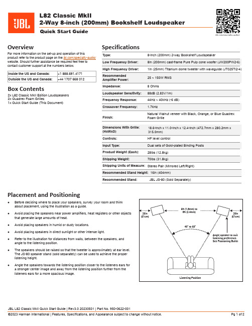
L82 Classic MkII2-Way 8-in ch (200mm) Bookshelf LoudspeakerQuick Start GuideOverviewFor more information on the set-up and operation of thisproduct refer to the product page on the /specialty-audio/ website. Should further assistance be required feel free to contact customer support at the numbers below.Inside the US and Canada:+1 888.691.4171Outside the US and Canada:+44 1707 668 012Box Contents2x L82 Classic MkII Edition Loudspeakers 2x Quadrex Foam Grilles1x Quick Start Guide (This Document)Placement and Positioning●Before deciding where to place your speakers, survey your room and think about placement, using the illustration as a guide.●Avoid placing the speakers near power amplifiers, heat registers or other objects that generate large amounts of heat.●Avoid placing speakers in humid or dusty locations.●Avoid placing speakers in direct sunlight or other intense light.●Refer to the illustration for distances from walls, between the speakers, and angle to the listening position.●The speakers should be raised so that the tweeter is approximately at ear level.The JS-80 speaker stand (sold separately) can be used to achieve the proper listening height.●Angle the speakers towards the listening position closer to the listeners ears for a stronger center image and away from the listening position further from the listeners ears for a more spacious image.SpecificationsRecommended Stand:JBL JS-80 (Sold Separately)Wiring and ConnectionsIMPORTANT! Wiring Precautions●Ensure that the positive (+) and negative (-) bare wire or spades DO NOT touch each other when connected to the binding posts as this will short out the amplifier channel.●Ensure that the appropriate polarity is maintained from amplifier to speaker to ensure proper phase for both speakers.4 Post Terminals / Dual Sets of Binding Posts Terminal Wiring Options2-Wire ConnectionsBasic single-wire connection from amplifierWe recommend using HF Positive and LF Negative.B-Wire ConnectionsTwo-wire connection from single amplifier Remove terminal straps before connecting.Bi-Amp ConnectionsTwo-wire connection from multiple amplifiers Remove terminal straps before connecting.+-Positive + Red Negative - Black+-+-Positive + Red Negative - BlackControls and AdjustmentsThis speaker features a HF level control that can be used to adjust the HF level independently from the level of the woofer. The default setting of 0dB represents a flat balance between the woofer and tweeter, however in some cases there may be a need to adjust the level of the tweeter.High Frequencies (HF Level) Adjustments●For rooms where the high frequencies sound bright, lower the relative HF level by turning the knob counterclockwise.●For rooms where the high frequencies sound dull, raise the relative HF level by turning the knob clockwise.Harman International Industries, Incorporated.8500 Balboa Blvd, Northridge CA 91329 United States.European Representative: Harman International Industries, Incorporated.EMEA Liaison Office, Danzigerkade 16G, 1013 AP Amsterdam, The Netherlands.UK Business Address: Ground Floor, Westside 2, London Road, Apsley, Hemel Hempstead, Hertfordshire, HP3 9TD, United Kingdom. © 2023 Harman International Industries, Incorporated. All Rights Reserved.JBL is a trademark of Harman International Industries, Incorporated registered in the United States and other countries.Features, Specifications, and Appearance subject to change without notice.。
高中英语 U2词汇讲解
感顿市安乐阳光实验学校高中英语译林牛津版必修二U2晨读在线假设你和几位同学成立了一个英语俱乐部,开展了为期两个月的活动。
现在,你将代表俱乐部在课堂上进行经验交流,请写一篇英语发言稿,主要内容如下:1.简要描述俱乐部开展的一项与英语有关的主要活动;2.谈谈你们开展该活动的收获。
注意:1.词数不少于120个;【范文欣赏】请进行完形填空(每空一词)Dear friends,I am very glad to have this chance to tell you something about our English club.These days,our main activity is 1.to collect the classic English movies from the Internet and watch them together.2.How interesting it is! And all of us do feel we benefit a lot 3.from the activity.By watching English movies,we gain a lot of knowledge about 4.the customs and lifestyles of the western countries,5.which we haven't known.Also,we can learn many latest English idioms and expressions.More importantly,we often compare notes in English after watching them,which makes us more interested 6.in learning English.I find 7.it is really a good way to improve our English.I hope more and more classmates can join our club 8.and share our experience.That's all! Thank you for listening.(137 words)【名师点评】文章条理清楚,层次分明,逻辑严密,能紧扣要点框架适当地增加细节,时态运用非常妥当。
m2ultra参数

m2ultra参数
摘要:
1.M2Ultra 参数概述
2.M2Ultra 参数的具体内容
3.M2Ultra 参数的应用领域
4.M2Ultra 参数的优势与不足
5.总结
正文:
M2Ultra 参数是一种在数字信号处理领域中广泛应用的参数,其主要用于描述音频信号的特征。
这种参数可以为音频信号提供丰富的信息,使得音频信号的处理变得更加精细。
M2Ultra 参数的具体内容包括多个方面,如音频信号的幅度、频率、相位等。
这些参数可以通过各种算法进行计算,以得到音频信号的详细特征。
M2Ultra 参数的应用领域非常广泛,包括音频压缩、音频增强、音频分析等。
通过使用这些参数,可以使音频信号的处理效果更加理想。
M2Ultra 参数的优势在于其能够提供音频信号的详细信息,从而使得音频信号的处理更加精细。
同时,这种参数计算简便,易于实现。
然而,M2Ultra 参数也存在一些不足。
首先,这种参数的计算需要消耗大量的计算资源,因此在实时处理音频信号时可能会存在困难。
其次,M2Ultra 参数的计算结果受到许多因素的影响,如音频信号的质量、计算方法等,因此在实际应用中需要进行适当的调整。
总的来说,M2Ultra 参数是一种在数字信号处理领域中非常有用的参数,
其能够为音频信号的处理提供丰富的信息。
