Agilent 仪器安装手册
Agilent HPLC原装工作站安装步骤1

20070207
王晓磊
1
1、一拖1工作站的安装 2、一拖2工作站的安装
20070207Biblioteka 王晓磊2一拖1工作站的安装
• “一拖一”就是一台电脑上连接一台LC • 首先是要准备两根普通网线,路由器一台 • 光盘放入光驱,打开“我的电脑”。进入G:
\
• (不同的电脑也许会不同,不一定是G:\)然后双击
20070207
王晓磊
3
• 执行SETUP.EXE后会出现让我们选择添加 仪器的对话框,我们选择“添加更改”。 一般情况下,不选择安装在C:\,我们可 以安装在如:D:
\PROGRAMFILES\CHEM32
• 点击“添加更改”后会出现下面的界
面…… 20070207
王晓磊
4
注意,这里要选择LC化学工作站。然后添加
20070207
王晓磊
17
• IP Address 就是在仪器配置里的IP地址,这里 的IP要和仪器配置里的一样,否则不能通信。 Host Name:LC的名称,这里随便取,只是方便 记忆。我们就取HPLC1。Comment可以不填。
Subnet: 255.255.255.0
Gateway可以填 192.168.0.1,当 然也可以不填。 最后点OK就OK 了。
王晓磊
11
• LC 的IP已经设置好了,确定就OK!
20070207
王晓磊
12
• 最后,保存后退出。
20070207
王晓磊
13
• 安装过程中,若系统提示你要重新启动, 请重新启动。
20070207
王晓磊
14
• Bootp最好在开始就把安装好, Bootp安装 非常简单,一路NEXT就OK了。下面看看 Bootp的配置。
安捷伦安装步骤
安捷伦安装步骤
1、在“N4010A测试驱动\N4010A_WLAN_CDROM_5.4.4”中找到
“安装①”文件夹,打开,安装“dotnetfx.exe”应用程序,OK。
2、在“N4010A测试驱动\N4010A_WLAN_CDROM_5.4.4”中找到
“安装②(安装Agilent IO)”文件夹,打开,选择“setup.exe”,安装应用程序。
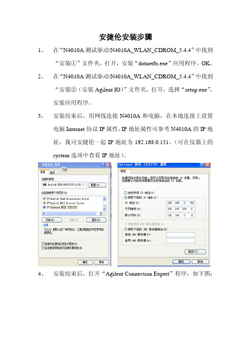
3、安装结束后,用网线连接N4010A和电脑,在本地连接上设置
电脑Internet协议IP属性,IP地址属性可参考N4010A的IP地
址,我司安捷伦一起IP地址为192.168.0.151。
(可在仪器上的
system选项中查看IP地址)。
4、安装结束后,打开“Agilent Connection Expert”程序,如下图:
在列表中选择LAN接口,点击鼠标右键,选择“ADD Instrument”,打开,在列表中选择LAN选项,点击OK,如下图。
5、在打开的窗口中选择“Find Instrument”,如下图
选择“Find Now”,如图
找到设备后,此时在列表中可看到有设备N4010A,鼠标右键选择ADD VISA Alias,出现图示内容。
用网线连接N4010A和电脑
时前面应该为“√”。
安捷伦仪器使用说明书中文

Alpha安捷伦B1500A半导体器件分析仪用户!ˉ的GUID安捷伦科技公司声明?安捷伦科技公司2005年,2006年,2007年,2008本手册的任何部分不得转载任何形式或通过任何手段(包括电子电子存储和检索或翻译成外国语言)事先同意MENT和安捷伦的书面同意作为由美国科技公司在美国和国际版权法。
手册部件号B1500-90000版2005年7月第1版,第2版,2005年12月2006年4月第3版第4版,2007年1月2007年6月5日,版第6版,2007年11月2008年10月7日,版安捷伦科技公司5301史蒂文斯溪大道95051美国加利福尼亚州圣克拉拉保证本文档中所含的物质是提供MENT!°为是,±,是苏如有更改,恕不另行通知,在以后的版本。
此外,最大而且,在适用法律法律,安捷伦提供任何保证,明示或暗示,关于本手册的任何信息所载,包括但不不限于隐含保证为杆的适销性和适用性特定用途。
安捷伦不得承担错误或偶然或在相应的损害赔偿连接TION的家具,使用,或每本文件或任何性能所载资料。
应该安捷伦与用户有一个单独的与保修的书面协议在这个物质的范围,涵盖记录与这些冲突条款,在保修则以协议arate中的协议为准。
技术许可硬件和/或软件描述这份文件是依照许可可用于复制或只在雅跳舞的许可条款。
有限权利如果软件在使用的一种表现美国政府的首要合同或道,软件交付和许可!°商业计算机软件!±ADFAR252.227-7014(1995年6月)的定义,或作为一个!°商业项目!FA±定义2.101(a)或°有限计算机软!洁具!±作为定义在FAR52.227-19(六月1987)或任何相当机构法规或合同条款。
使用,重复或disclo的软件肯定是受安捷伦科技nologies!ˉ标准商业许可条款和非DOD部门和美国政府机构没有获得更大而不是限制权利定义在FAR 52.227-19中(C)(1-2)(6月1987年)。
Agilent GCMS化学工作站软件安装手册(For 7890_5975 and 1701EA chemstation)

GCMS化学工作站软件安装手册(For 7890_5975 and 1701EA chemstation)安捷伦科技有限公司生命科学与化学分析仪器部1、打开电脑,将工作站光盘放入后,自动跳出Internet Explorer窗口,点“Yes”(注意:在安装前先将windows firewall 设到“off”)2、如安装英文版,选择点击English图标箭头3、出现如下图的窗口后,选择点击红箭头所指的Agilent IO Libraries4、在跳出的窗口中选择“ Run”5、选择”Run”, 继续安装6、点“ Install” 安装Microsoft Visual C++ 2005 Redistributable7、自动安装Microsoft NET Framework 2.0, 点” Next”继续8、选中” I accept the terms of the license Agreeement”,继续安装9、Microsoft NET Framework 2.0安装的过程10、Microsoft NET Framework 2.0 安装完成11、点“Next”,继续安装12、选中“ I accept the terms of the license agreement”, 点“Next”继续13、选中“Typical”,点Next继续IO Libraries安装14 选“Install”,继续安装15 安装完毕,选“Finish” 结束IO Libraries安装16、IO Libraries安装后,开始安装MSD Chemstation。
选中G1701 MSD Productivity Chemstation, 开始安装。
17、点击“Run”, 继续安装18、点击“Run”, 继续安装19、选中“English”, 安装英文版的化学工作站20、点击“Next”,继续安装化学工作站。
21、选中” I accept the terms of the license Agreeement”,点Next继续安装22、填入软件注册码(Registration Number)及客户信息,点Next继续23、选择安装的路径,点Next继续安装24、在窗口中,点Next继续安装25、点Install继续安装26、安装完毕,选“Yes” ,点“Finish” ,电脑重新启动。
Agilent G1701DA MSD ChemStation安装手册
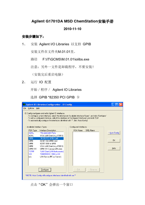
Agilent G1701DA MSD ChemStation安装手册2010-11-10安装步骤如下:1、安装Agilent I/O Libraries 以支持GPIB安装文件在文件夹M.01.01里。
路径F:\IT\GCMS\M.01.01\iolibs.exe注意:另外一文件是卸载程序,不要安装!(安装完后重启电脑)2、运行IO 配置开始/程序/Agilent IO Libraries选择GPIB *82350 PCI GPIB 卡点击“OK”会弹出一个窗口单击“OK”显示“IO 配置”屏幕,在已配置的接口列中,选择GPIB0单击编辑,出现“GPIB 卡配置”屏幕MSD ChemStation 要求使用82350B 卡,尽管MSD Productivity Software使用的SICL 接口名称为“hp82341”。
将SICL 接口名称【SICL Interface Name】更改为hp82341 (“hp”必须是小写字母),使用滚动箭头,将总线地址更改为30,【Bus Address】单击确定接受更改。
配置完成。
重新启动计算机永久保存设置。
3、安装Agilent MSD ChemStation 软件安装文件在文件夹“G1701DA D.03.00 SP1”里路径F:\IT\GCMS\G1701DA D.03.00\G1701DA D.03.00 SP1\MSD ChemStation重新启动计算机以完成软件安装4、安装“NIST05a”软件安装文件在文件夹“NIST05a”里路径F:\IT\GCMS\NIST05a5、在MSD ChemStation 中配置仪器按GPIB方式安装重启,完成。
Agilent Technologies G2570A 6850 GC MSD 系统 设置与安装手册
G2570A 6850 GC/MSD 系统设置与安装声明© Agilent Technologies, Inc. 2005按照美国和国际版权法的规定,未经Agilent Technologies, Inc. 事先同意和书 面许可,不得以任何形式或采取任何手段(包括电子存储和检索或翻译成其他语言)复制本手册中的任何内容。
手册部件号G3170-97001更换部件号 G2589-97006版本第一版,2005 年 6 月美国印刷Agilent Technologies, Inc.5301 Stevens Creek BoulevardSanta Clara,CA 95052担保本文档中包含的材料按“现状”提供,若在后续版本中发生更改,恕不另行通知。
而且,在适用法律允许的最大范围内,Agilent 不对本手册及其所包含的信息做出任何明确或暗示的担保,其中包括但不限于对适销性和对具体用途适用性的暗示的担保。
Agilent 不对因提供、使用或执行本文档或其中所包含的信息而造成的任何错误或任何意外或附带的损失承担责任。
如果 Agilent 与用户签署有单独的书面协议,且协议中涉及本文档所含材料的担保条款与上述条款相冲突,则该书面协议中的担保条款具有优先法律效力。
安全声明小心标记表示存在危险。
它表示在执行某个操作步骤或操作方法时必须加以注意;如果操作不当或没有遵守相应的规程,则可能会导致产品损坏或重要数据丢失。
只有完全理解并满足指定的条件时,才可以忽略小心声明的要求继续进行操作。
警告标记表示存在危险。
它表示在执行某个操作步骤或操作方法时必须加以注意;如果操作不当或没有遵守相应的规程,则可能会导致人身伤亡。
只有完全理解并满足指定的条件时,才可以忽略警告声明的要求继续进行操作。
声明Microsoft® 和 Windows® 是Microsoft 公司在美国的注册商标。
目录1概述前言 8G2570A 系统说明 9配备 MSD 的 6850 GC 105973N MSD 10MSD ChemStation 硬件和软件 10支持的附件 11重要安全警告 12MSD 的多个内部部件均带有危险电压 12静电释放将损坏 MSD 的电子设备 13许多部件都带有危险的高温 13氢气安全 15操作 GC/MSD 的特殊危险 16MSD 中积聚氢气 16注意事项 19化学安全 20安全与规范认证 21信息 21符号 22电磁兼容性 23噪音发射声明 23仪器清洗 24仪器的回收利用 24其他文档 242现场准备工作概述 26客户的责任 27Agilent 的责任 27接收系统 29运输和卸货 29检查损坏 29存放 30打开包装 30空间和重量要求 31通信要求 32电话 32现场网络 32电气要求 33主要组件的电压范围 33电源配置 34电源要求 35电源插头和电线 36电气方面的其他注意事项 37空气调节要求 38温度、湿度和高度 38空气粉尘 39废气排放 39通风(废气)橱 40载气要求 41调节阀、管线和接头 41实验室供应要求 42清洗溶剂 42数据系统供应 42备用部件和消耗品 43安装和验证 46安装 46验证 46灵敏度规定 473安装概述 50安装目的 50客户的责任 51开始之前 52安装 MSD ChemStation 计算机 53安装 GC 54将氦气管线连接到 GC 55重新配置色谱柱出样口 59安装 MSD ChemStation 软件 64将色谱柱插入分流/非分流进样口 64老化色谱柱 65准备安装 MSD 66准备真空系统 67连接 MSD 和 GC 69配置 GC/MSD 仪器 74将色谱柱安装到 GC/MSD 接口 75验证 EI 系统性能 78准备 MSD 78验证自动调谐性能 79验证灵敏度性能 794检查清单客户责任 82安装中未包括内容 82检查包装箱内的材料 82开始之前 82安装 MSD ChemStation 83安装 GC 83将氦气管线连接到 GC 83重新配置色谱柱出样口 83安装 MSD ChemStation 软件 84将色谱柱插入分流/非分流进样口 84调节色谱柱 84MSD 准备工作 85安装 MSD 86准备真空系统 86连接 MSD 和 GC 86配置 GC/MSD 仪器 87将色谱柱插入 GC/MSD 接口 87验证 EI 系统 89技术支持 89A电源线G2570A 6850 GC/MSD 系统设置与安装1概述前言 8G2570A 系统说明 9重要安全警告 12氢气安全 15安全与规范认证 21仪器清洗 24仪器的回收利用 24其他文档 24本节所提供的信息涉及如何识别您所使用的 MSD 的特定类型,以及 如何正确清洗该仪器。
Agilent GCMS(操作说明)

如: 选择恒流flow,输入1.7(ml/min)。
Page 25
Agilent Restricted
三、方法编辑
4、 GC 参数设定 (Instrument→GC Parameters)
4.5 柱温箱温度参数设定
点击图标
,进入柱温参数设定。在温度框内输入温度,选中“Oven Temp On ”左边
PreInj—进样前,PostInj-进样后;Volume(ul)—清洗的体积 ;Sample Wash—用样品洗针次数; Solvent A Wash—溶剂A洗针的次数;Solvent B Wash—溶剂B洗针的次数;Pumps—赶气泡针抽吸 的次数。
Page 22
Agilent Restricted
Inlet/Vacuum/Oven。 点击1进入“Install Column 1” 柱子配置界面(与GCMS相同)。
Page 17
Agilent Restricted
三、方法编辑
1、 GC配置编辑—柱参数设定:柱子配置界面
点击“Replace with Inventory”钮,可选择添加其他柱子。 也可以在Edit Properties of Installed GC Column窗口中填入柱子的参数,点击OK,完成
,选Ion Source,填入离子源参数。建议:进行手动调谐时以工厂配有的调谐文
件为基础
Page 7
Agilent Restricted
二、调谐步骤
2. 手动调谐 2.2 MS1参数:在Manual Tune子窗口内,选MS1,填入MS1参数。
Page 8
Agilent Restricted
二、调谐步骤
Page 2
Agilent Restricted
AgilentGCMS(操作说明)
Agilent GCMS(操作说明)Agilent GCMS 操作说明1. 开机和关机1.1 开机1.打开实验室门,确保环境通风良好。
2.接通GCMS电源线,按下电源按钮,等待仪器自检完成。
3.登录GCMS操作系统,根据实验室规定输入用户名和密码。
1.2 关机1.完成实验后,确保所有气体通道已关闭。
2.在操作系统中选择“关机”,等待仪器安全关闭。
3.关闭电源按钮,拔掉电源线。
2. 样品制备2.1 样品瓶准备1.清洗并干燥样品瓶,确保无任何杂质。
2.精确称取适量样品,转移至样品瓶中。
3.加入少量内标物质,以辅助定量分析。
2.2 样品进样1.打开样品瓶,用进样针取一定量样品。
2.将进样针插入GCMS进样口,缓慢推入。
3.等待样品完全进入进样口,然后拔出进样针。
3. 实验操作3.1 柱温设定1.在操作系统中选择“柱温设定”模块。
2.根据样品性质设置合适的柱温,如50℃至300℃。
3.2 载气选择1.在操作系统中选择“载气选择”模块。
2.根据实验需求选择合适的载气,如氦气或氮气。
3.3 流量控制1.在操作系统中选择“流量控制”模块。
2.设定载气流量,确保实验稳定进行。
3.4 检测器操作1.在操作系统中选择“检测器操作”模块。
2.根据实验需求,调整检测器参数,如温度、电流等。
4. 数据处理与分析4.1 数据采集1.开始实验后,操作系统将自动采集数据。
2.实验过程中,确保仪器稳定运行,避免干扰。
4.2 数据处理1.实验结束后,将数据导入数据处理软件。
2.利用软件进行谱图分析、峰识别、定量计算等操作。
4.3 结果输出1.完成数据处理后,将结果输出为报告。
2.报告应包含实验数据、谱图、定量结果等。
5. 日常维护1.定期检查仪器设备,确保运行正常。
2.检查样品制备过程,确保样品质量。
3.观察数据处理与分析结果,发现问题及时解决。
6. 安全与环保1.操作过程中,严格遵守实验室安全规定。
2.确保实验室通风良好,避免有害气体泄漏。
Agilent软件操作说明书1.1
Agilent软件操作说明书Agilent软件操作说明书 (1)1 概述 (2)更新时间 (2)版本 (2)更新内容 (2)2008.9.15 (2)V1.1 (2)1.添加License申请 (2)2.添加软件存在问题总结 (2)3.添加前台reporter应用功能 (2)2 功能介绍 (2)2.1 License的安装 (2)2.2 运行软件 (5)2.3 创建工程 (6)2.4 设备添加..................................................................................... 错误!未定义书签。
2.5 导入基站数据 (16)2.6 测试过程中的界面试图 (22)2.7 测试脚本的配置 (28)2.7.1 Call_Control (29)2.7.2 FTP下载 (30)2.8 Report的分析 (35)2.9 数据卡的使用 (40)3 附件 (44)1概述通过Agilent软件能够对该地区的3G网络的进行测试,包括语音电话,视屏电话,FTP下载等,结合测试结果发现3G网络中存在的问题,为3G的网络优化提供必要的依据。
2功能介绍2.1 License的安装在运行软件之前需要安装license得到软件的使用权。
如何获取Agilent E6474 License1.若无License,则MapX不能正确显示2.选择Programe File/Agilent Wireless Solution/E6474-X/Utilities/License Manager3.选择Commuter License中的Remote Commuter License,得到Current Computer 的MachineCode,发送给相关人员获取License.中Load并安装,即OK2.2 运行软件如上图所示,打开软件后出现上图所示的界面,点击红色区域中的Collect data now按钮进入软件。
安捷伦的原子吸收仪安装手册
3
目录
1.简介..............................................................................................5 1.1安装指导 5
1.2推荐的个人电脑配置 5 1.3预安装清单 7
1.4“警告”和“注意”消息 9 2.适当的工作区域 ..........................................................................11
备注个人电脑必须具有一个备用的 PCI扩充槽,用于插入 Agilent PCI-IEEE 接口电路板。
建议这是推荐的配置,建议你购买新的个人电脑。 Intel®Pentium®2.8GHz处理器、512MB内存、17英寸 SVGA显示器、 支持 1024x768分辨率的图形显卡、4GB或以上硬盘、24速光驱、32 位声卡和扬声器、Windows®XP(Service pack2)操作系统、 2个 RS232串行端口。
如果您需要帮助或者操作者培训的详细内容,请联系您的 Agilent 代表。
备注:本手册上的所有资料在出版时是精确的。如果需要获取最新的资料,请 联系您当地客户支持代表。
1.1安装指导
Agilent 客户支持代表需要最少四个小时安装设备,如果需要安装 附件,则最多需要八个小时。安装包括:
光谱仪的安装 基本的客户培训
国际传真: +31118623193
网址 Agilent网址如下: http: //
Agilent Australia Pty Ltd是本文件和任何有关软件的版权所有者。根 据相关法律,对于本文件或软件来说,在全部或者部分拷贝、复 制、转化或者将其转化为电子文档或者其他可借助阅读器阅读的形 式之前必须获得 Agilent Australia Pty Ltd的书面许可。 1994年在澳大利亚首次出版。 1995年、1997年、1998年、2000年、 2001年、2002年、2003年、2007年更新。如果您对本手册有任何看 法,请联系 Agilent澳大利亚公司市场交流经理(上面已提供地址)。
agilent8860气相色谱仪操作手册

agilent8860气相色谱仪操作手册第一节:安全操作1.在使用Agilent 8860气相色谱仪之前,务必熟悉仪器的基本操作和安全规程。
2.在操作仪器前,确保仪器处于稳定的平台上,并接好电源。
3.使用之前,请先检查仪器的连接线、进样器和柱子是否正常。
4.在操作仪器时,应穿戴好实验室所必需的个人防护设备,例如实验手套、实验眼镜等。
5.仪器操作时,请确保实验室通风良好,并远离易燃和有毒物质。
6.在操作过程中,严禁随意修改或拆卸仪器的任何部件。
7.使用完毕后,请及时关闭仪器电源,并进行相关清洁和维护工作。
第二节:仪器的基本组成及操作步骤Agilent 8860气相色谱仪主要由以下部分组成:进样器、柱子、检测器和控制系统。
下面将介绍仪器的基本组成和操作步骤。
1.进样器:进样器是将待测样品引入柱子的部分,需要注意的是,进样器应有一定的温度控制功能,以保证样品能够顺利进入柱子。
在进行进样操作前,需要将待测样品准备好,并按照要求将样品装入样品瓶中,再将样品瓶插入进样器。
2.柱子:柱子是Agilent 8860气相色谱仪中的重要组成部分,可以根据实际需要选择不同种类的柱子。
在操作过程中,要注意柱子的安装和更换。
柱子的安装应按照仪器使用手册中的指示进行,避免出现不必要的损坏。
3.检测器:检测器用于测量样品在柱子中通过时产生的信号,并将其转化为可读的结果。
Agilent 8860气相色谱仪常用的检测器有火焰离子化检测器(FID)、电子捕获检测器(ECD)、氮磷检测器(NPD)等。
在操作检测器前,要先进行预热,以保证其正常工作。
4.控制系统:控制系统是用于控制仪器各部分正常工作的关键部件。
在操作过程中,可以通过控制系统设置温度、流速等参数。
同时,控制系统还可以监测仪器的工作状态,如温度、压力等。
第三节:Agilent 8860气相色谱仪的日常维护1.每天使用之前,检查仪器是否清洁,无灰尘和杂质,并且所有连接线是否牢固。
Agilent Installation 说明书 NPD ECD Chemical Filters

Copyright© 2000 Agilent Technologies Printed in USA Dec 2000 Agilent Part No. 19231-90767
3
Installing the NPD/ECD Chemical Filters Accessory 19199N Preparing the Instrument
10. Disconnect the outlet fitting plate from the top of the filters. Remove the flow lines from the filters. Route these lines to the detector flow manifold.
9. If an auxiliary flow panel is present: a. Loosen the flow panel mounting screws. b. Slide the chemical filter mounting bracket (from the top) between the pressure regulators and the auxiliary flow panel. Position the top hole in the chemical filter bracket over the top mounting screw of the auxiliary flow panel. c. Tighten the auxiliary flow panel mounting screws.
Agilent GC 系统 GC化学工作站 安装手册

Agilent GC 系统化学工作站GC 化学工作站安装手册Agilent Technologies, Inc.2850 Centerville Road Wilmington, DE 19808-1610© 安捷伦科技公司版权1994-2002版权所有未经书面许可不得擅自复制修改或翻译符合著作权法者除外部件号 G2070-970092002 年 3 月第一版美国印刷Microsoft ® Windows NT ®与Windows 2000® 是微软公司的美国注册商标Windows™ 与 Excel™ 97是微软公司的商标声明本书内容如有改变恕不另行通知安捷伦科技公司不对本材料及由此引出的任何商务和特种用途承担任何责任安捷伦科技公司对本手册中可能有的错误或与装置性能及材料使用有关内容而带来的意外伤害和问题不负任何法律责任68506890 或 5890 气相色谱仪GC 化学工作站安装手册目录第 1 章安装准备Agilent GC 化学工作站概述 (8)从何开始 (11)PC 要求 (12)软件兼容性 (13)参考资料 (14)认识 GC 化学工作站 (19)化学工作站 CD-ROM 的内容 (20)第 2 章安装局域网(LAN)通讯接口卡关于 LAN (24)安装LAN接口卡 (24)LAN 电缆连接 (25)PC LAN 驱动器 (25)如何安装 CAG 引导服务器程序 (26)第 3 章安装 GPIB 接口卡数字数据与模拟数据的采集 (28)安装GPIB接口卡 (30)GPIB 电缆连接 (31)配置82341或82350 GPIB 卡 (32)在Windows NT 4.0下配置接口驱动器 (32)安装新的I/O 库 (32)更新现有的I/O库 (38)在Windows 2000中配置接口驱动器 (45)安装新I/O库 (45)安装过程中生成了哪些图标 (58)5目录第 4 章安装化学工作站概述 (60)安装步骤 (61)安装化学工作站指南 (67)在客户机/服务器上安装或升级化学工作站 (68)安装控制图表报告 (72)第 5 章增加或改变化学工作站部件增加或改变部件 (74)第 6 章仪器配置仪器系统连接 (80)启动配置编辑器 (82)配置6850 GC (83)保存所做的配置 (87)配置6890 GC (88)保存所做的配置 (93)配置5890 GC (94)保存所做的配置 (98)第 7 章验证和启动化学工作站化学工作站安装认证 (100)启动化学工作站 (104)附录 A3365 化学工作站输入数据和方法文件 (110)61安装准备安装准备Agilent GC 化学工作站概述8Agilent GC 化学工作站概述关于 68506890和5890气相色谱仪带有LAN卡的6850的气相色谱仪使用化学工作站软件可以最大限度地发挥其优良性能化学工作站能够全面控制并自动运行GC和其他仪器包括自动进样器色谱柱和检测器选件的许多功能带有GPIB接口的6890或5890气相色谱仪带有LAN卡的 6890 或 6850 气相色谱仪使用化学工作站软件可以最大限度地发挥其优良的性能化学工作站能够全面控制并自动运行GC和其他仪器包括各种自动进样器色谱柱和检测器选件的许多功能化学工作站能够• 使用自动液体进样器自动进样• 控制5890系列 II 气相色谱仪上的阀或用 5890 GC 增加的 19405B 进样器/事件控制器来控制阀和/继电器• 当自动进样器安装在GC的前面后面或进样口的两边时可以实现自动液体进样器的自动化• 在自动液体进样器上加一样品盘化学工作站可提供对100个样品瓶的自动访问而且通过增加G1926A条形码读出器来识别每个样品瓶的条形码以实现完全自动化安装准备Agilent GC 化学工作站概述9仪器系统连接化学工作站软件通过 GPIB 数据传输线或 LAN 实现与分析仪器的联系• 第一章概述了化学工作站及辅助学习资料•第二章介绍如何在用户计算机上安装 LAN 通讯接口卡•第三章阐述如何安装 GPIB 接口卡• 第四章叙述如何安装新的化学工作站软件•第五章介绍如何把所增加的仪器部件接到A.09.xx 化学工作站上• 第六章叙述装入软件后如何设置仪器• 第七章叙述如何启动新安装的化学工作站• 在附录中讲述如何把数据和方法文件从3365化学工作站上输入化学工作站 A.09.xx 版本上Esc Enter 6890 GC 化学工作站6890 气相色谱仪自动液体进样器5890 气相色谱仪安装准备从何开始从何开始如果您刚刚收到Agilent 化学工作站而且是第一次使用那么就从这里开始如果您准备自己安装那就先用一些时间通读本手册按照本手册的顺序阅读是很重要的在阅读后面章节时应理解前面章节里所介绍的术语和资料如果某部分您不理解请与安捷伦科技公司联系寻求帮助如果化学工作站是完全由安捷伦科技公司安装的您也许想浏览一下本手册以了解如何配置仪器系统请参照下表所列页码详细阅读有关章节本手册假设您已熟悉了Microsoft ® Windows NT ® 或 Windows 2000®安装类型阅读章节新安装或升级第 61 页套装软件包第 61 页在网络上安装用户/服务器第 68 页在现有的A.09.xx 版本的化学工作添加或修改仪器部件第 74 页输入 3365 化学工作站输入数据和方法文件第 110 页安装准备PC 要求PC 要求化学工作站软件要在下列 PC 环境下运行IBM 兼容计算机Microsoft Windows NT 或 Microsoft Windows 2000 操作环境并安装相应的 Service Packs 成功运行化学工作站软件所需硬件的最低要求是•使用Intel 奔腾处理器166 MHz 或更高的的PC• Super VGA 显示器800600的分辨率• 1.2 GB 硬盘• CD-ROM 驱动器•48 MB RAM 用于配置一台二维仪器每添加一台仪器要增加8 MB RAM或64 MB RAM 用于配置一台三维仪器LC LC/MSD 或 CE要添加应用程序如 ChemStore 数据库则要增加8 MB RAM推荐使用128 MB或更高的RAM 的奔腾 III 600 MHz或更快的PC安装准备软件兼容性软件兼容性• 与低版本的化学工作站 A.03.xx版 A.04.xx版 A.05.xx版 A.06.xx与A.08.xx得到的分析资料完全兼容• 在低版本的DOS版化学工作站上获得的气相色谱液相色谱和毛细管电泳数据均可用新版本处理• 在低版本的化学工作站上开发的LC CE分析序列可不受限制地在新版本上运行在低版本的3365化学工作站上开发的GC分析序列在新版本上只能重新处理运行• 在低版本的化学工作站上开发的LC和CE分析方法可直接用于新版本而无需转换在低版本的3365化学工作站上开发的GC方法不包含宏并保持在同一型号的仪器如 5890 GC开发和转换的均可转换在新版本上运行• 前运行和/或后运行程序可能需要修改或重新编写• 屏幕保护软件不能和化学工作站同时使用屏幕保护要使用PC的资源这样在GC采集大量数据时造成数据丢失安装准备参考资料参考资料化学工作站软件提供了内容广泛的学习资料文件资料•本手册及其它安装手册介绍了如何通过安装必要的硬件和软件来准备操作化学工作站安装手册是专门针对要使用化学工作站的各种仪器部件的在仪器到货时用户可能会收到不只一本手册• 了解您的化学工作站手册讨论了化学工作站的概念以增加您对化学工作站工作原理的理解•在线宏编程指南介绍如何使用功能强大的命令组自定义和扩展化学工作站的功能从帮助Help 菜单选择 Commands 命令就可访问这一在线指南有关安装与维护的说明•自述README 文件和软件状况公告Software Status Bulletin 载有某些方面的信息比如在印刷本手册时没有收入的增加的新特性已知工作环境和勘误从任务栏的开始Start 菜单选择 Programs/ChemStations/readme.txt 就可访问自述文件readme.txt 也放在化学工作站的CD-ROM 的\G2070\Disk1目录中软件状况通报在化学工作站 CD-ROM 的 Support\SSB 目录中•自动更新的记录本Logbook 记录操作和修正如有必要过程中所发现的任何错误从视窗View 菜单选择Logbook 记录本然后双击就可访问记录本最近的输入在表的顶部• 用户贡献库User-Contributed Library 包括由内部和用户创立的应用和宏可帮助用户优化安装以满足特定的需要• Microsoft Windows NT 或 Windows 2000在线帮助以及使用手册•每台仪器包括PC 机的硬件手册安装准备参考资料在线帮助系统化学工作站内容丰富的在线帮助系统为用户提供参考资料逐步操作说明和完整的交互式参考命令组此帮助系统中有两种方法可访问帮助还有三种检索应用工具访问在线帮助在任何对话框用鼠标单击帮助Help按钮或按<F1>键就可访问上下文关联的参考资料在线参考资料Online reference material解释了化学工作站的每个功能并给出完成这些功能所需要的指令安装准备参考资料从主菜单选择Help帮助就可访问包括Help Topics帮助标题Commands命令和Tutorial个别辅导的三个选项• 从帮助Help)菜单选择帮助标题Help Topics就可显示一个化学工作站系统的目录表包括化学工作站A.09.xx版本的新特点单击适当的条目然后再单击您想阅读的标题这些标题提供了在线逐步操作说明online step-by-step instructions和仪器特别帮助instrument specific help在线逐步操作说明包括最常用的化学工作站操作比如怎样运行方法对数据文件进行积分标注色谱图生成报告等等安装准备参考资料• 从帮助菜单选择命令Commands就可显示一个化学工作站的命令目录和在线宏编程Micro Programming指南单击适当的条目然后再单击您想阅读的命令命令在线帮助包括每条命令的详细资料如名称分组语法参数讨论返回值和举例可能的地方宏编程指南介绍如何用命令组编制适于用户自己使用的化学工作站安装准备参考资料• 要访问指南部分可从帮助Help菜单选择Tutorial当前化学工作站视窗可实现的操作就会显示出来为化学工作站软件的一部分还提供了一个综合指南integrated tutorial这一自定进度的逐步深入的介绍将帮助您学习如何使用选择特性如果您是新用户请从头至尾阅读这一培训教材指南Tutorial通过逐步指导引导您熟悉每一项操作您可以选择启动任务Start Task按钮来自己进行操作也可以选择演示Show Me按钮来得到一个操作步骤表如果您选择演示Show Me按钮化学工作站将执行第一步操作并为您提供一个完成这一任务的其它步骤表可在自己的数据文件方法和分析序列或在帮助文本文件中指定的样品文件里使用上述逐步操作指导帮助检索应用工具帮助系统中有三种检索可用它们是目录Contents索引Index和查找Find• 目录Contents列出了帮助标题的目录单击Contents然后按照系统提示进行• 索引Index按字母顺序列出了所有帮助标题单击Index然后按照系统提示进行• 查找Find可以在整个文件中搜索特定的词或词组在第一次使用查找时Windows将在您的帮助系统中创建一个所有单词的数据库要创建数据库单击Find然后按系统提示进行数据库一旦建立系统就不再提示您进行这一过程要进行全文检索单击Find然后按系统提示进行安装准备认识 GC 化学工作站认识 GC 化学工作站当安装完成并可操作之后GC化学工作站就变成一个完整的具有多种功能的个人工作站在仪器到货时组成工作站的几部分可能装在了一起也可能没有虽然用户特定的计算机看起来也许与下图不尽相同但功能是相似的打印机显示器鼠标CD-ROM键盘安装准备化学工作站 CD-ROM 的内容化学工作站 CD-ROM 的内容化学工作站软件是在CD-ROM上提供的此 CD-ROM 包括了属于化学工作站产品家族的所有仪器部件的可执行文件要在工作站上安装一个仪器部件必须输入该部件有效的许可注册号码这些号码能打开被保护的CD-ROM原装产品中含有这些号码这是您的特许证明安装认证应用程序化学工作站带有一个应用程序用来验证和记录新安装的工作站的完全性和完整性在化学工作站软件安装完以后从窗口任务按钮通过Programs/ChemStations/ Installation Qualification来访问安装认证应用化学工作站软件状况通报软件状况通报SSB是安捷伦科技公司通过发布化学工作站应用软件产品现状来反映缺陷记录跟踪和维护方法结果的文本文件已知缺陷附加信息SSB在化学工作站 CD-ROM的Support\SSB目录中如果您有软件合同您将定期每年至少两次收到化学工作站软件状态公告Software Status Bulletin化学工作站版本历史版本历史是针对那些升级为新的应用软件版本以后可能需要验证分析数据系统的用户版本历史Revision History包含了化学工作站产品家族中所有产品的版本历史版本历史文件在化学工作站CD-ROM的 Support\History目录中安装准备化学工作站 CD-ROM 的内容21用户贡献库该库的内容是为了帮助用户为其特殊需求而开发和优化安装以使他们从仪器投资中获得最大效益该库中的内容既来自安捷伦内部也来自用户每一项所贡献的内容都要进行功能测试但不必象实际产品那样需通过全部的正式测试步骤所以安捷伦科技公司并不能保证这部分内容的正确性用户贡献库User-Contributed Library 包括应用和宏每一项贡献都带一个可用任何ASCII 文本编辑器阅读的专门的自述(README.TXT)文件化学分析部补充信息化学分析部补充信息Chemical Analysis Group Supplemental Information 包括化学工作站软件公布后发货的成套装置所需的附加媒体绘图驱动程序和打印机驱动程序对于特定驱动程序及如何安装方面的详细资料请参看随CAG 补充资料Supplemental Information 所提供的文件化学分析部补充信息Chemical Analysis Group Supplemental Information 由化学工作站计算机成套设备附带的 CD-ROM 提供安装准备化学工作站 CD-ROM 的内容222安装局域网(LAN)通讯接口卡• 68506890 GC• 35900E A/D 转换器安装局域网(LAN)通讯接口卡关于 LAN24关于 LAN化学工作站软件 A.09.xx版本为6850 GC6890 GC和 35900E A/D 控制部件提供基于局域网LAN的仪器控制和数据采集功能只要把带化学工作站的仪器连接在 LAN 上就可以很容易地控制和监视仪器通过由所支持的单一的LAN化学工作站可以在距离长达100 m 的地方控制您的仪器或通过在世界任何地方由网络管理人员所支持的TCP/IP网来控制在LAN上的每台化学工作站可以控制四台仪器在LAN上可以连接任何数量的化学工作站安装LAN接口卡在连接化学工作站PC机或任何让LAN进行控制的仪器之前要保证在仪器上已经安装了局域网LAN通讯接口卡有关在计算机上或在某一台要用化学工作站控制的仪器上安装LAN卡的详细资料参见LAN卡附带的文件安装局域网(LAN)通讯接口卡LAN 电缆连接25LAN 电缆连接所支持的LAN 配置是一个以太网IEEE 802.3工业标准的10-Mbps 10 Base-T 局域网连接插座和LAN 卡的电缆类型为带有RJ-45插头的 34或5 UTP 电缆的最大距离为100 m 这一配置所支持的服务器只能是由化学工作站安装盘提供的CAG 引导程序服务器不适应这些规定的LAN 配置必须由网络管理人员所支持PC LAN 驱动器PC 安装的Windows 必须装有传输通信互联网协议TCP/IP 所支持的文件参见有关装载TCP/IP 协议支持文件和 LAN 卡软件驱动程序的详细资料Windows 需要由 LAN 卡制造商所提供的软件驱动程序在LAN 上每个LAN 卡都需要特定的IP 地址子网掩码和缺省网关如果在分配这些数码时可需要帮助参阅CAG 引导服务器程序的在线文件化学工作站插座仪器仪器仪器仪器PCPC打印机化学工作站PC安装局域网(LAN)通讯接口卡如何安装 CAG 引导服务器程序26如何安装 CAG 引导服务器程序CAG引导服务器程序是用于仪器IP地址的中心管理和分配CAG引导服务器程序不必像化学工作站一样放在同一PC上它可以放在任一与LAN连接的PC上在装有上CAG引导服务器程序的PC必须运行Windows NT 或Windows 2000并必须安装有TCP/IP 支持的文件安装CAG引导服务器程序1.启动Windows 并在CD-ROM驱动器中插入化学工作站的光盘2.在任务按钮的启动菜单上选择Start/Run3.在命令行上键入drive:\bootp\Setup然后单击OK如D:\bootp\Setup4.按照提示在PC上安装CAG引导服务器程序5.从启动菜单上选择启动程序然后从帮助菜单上选择Help Topics查阅有关使用CAG引导服务器程序配置LAN的资料必须运行CAG引导服务器程序来开始化学工作站和仪器之间的通讯在启动了通讯之后不必要再运行CAG引导服务器程序使化学工作站和LAN控制的仪器之间进行全面的通讯如果仪器掉电必须运行 CAG 引导服务器程序通过LAN来连接化学工作站和各自仪器的联系3安装 GPIB 接口卡• 68905890 GC • 35900 A/D 转换器安装 GPIB 接口卡数字数据与模拟数据的采集28数字数据与模拟数据的采集要使化学工作站软件与安捷伦的分析仪器获得最佳性能一定要安装 LAN 或GPIB 通讯接口卡采集数字数据不过化学工作站也可用于通过下列三种模数转换器之一相连接的其它仪器或装置• 35900C需要 GPIB接口卡• 35900D只需要Windows NT• 35900E需要 LAN 或 GPIB接口卡为实现 PC 机上化学工作站与所用分析仪器之间的连接PC机必须安装有适用的信号传输接口卡 GPIB/LAN和/或35900D虽然35900D与A.09.xx化学工作站相兼容但安捷伦科技公司已不再提供这种部件安装成套设备若从安捷伦科技公司购置了成套设备GPIB/LAN接口卡化学工作站和仪器组件就已经安装好了可直接进入第六章的配置 6850 GC6890 GC或5890来配置新的GC若需要增加一个部件请参看第五章增加或改变化学工作站部件小心在安装GPIB卡时一定要装有IRQ IRQ的冲突会导致系统不可预料的问题安装 GPIB 接口卡数字数据与模拟数据的采集29安装接口卡在安装化学工作站软件之前计算机硬件必须要安装一个或几个下面所列的接口卡• GPIB 82341板或 GPIB 82350 卡安装方法见下一页说明• 35900D 卡在安装 AD 化学工作站手册中说明• LAN 卡 在第二章中有说明GC 与接口的可能性LAN 卡82350 GPIB 82341 GPIB 6850是否否6890A / Plus 是是是6890N 是否否5890否是是35900C 否是是35900D 已取消已取消已取消35900E是是是安装 GPIB 接口卡安装GPIB 接口卡30安装GPIB 接口卡由于 82350 GPIB 和 82341C GPIB 卡可安装在不同的计算机上因此下文所述的安装步骤是通用的若在安装过程中遇到困难请查阅计算机手册或向经销商咨询82341 GPIB 接口卡用于Windows NT 和95该接口卡要求用户安装完此卡后安装标准接口控制库SICL参见配置 82341 GPIB 接口卡完成GPIB 电缆的连接由于该接口卡为即插即用式因此不必设置转换开关82350 PCI 高效GPIB 接口卡该接口卡要求在PC 中有一个空的PCI 插槽如要安装它请按照下面对卡的说明或安装82341卡的说明进行安装将卡插入PCI 插槽安装完卡后再安装I/O 库并按后面的说明配置82350卡警告在打开任何机箱盖之前关闭计算机和所有接上电源的装置并拔下插头在安装此卡时切记要带上防静电腕带1.关闭计算机并拔下插头然后打开计算机主机箱盖2.选择任一空插槽不过最好不要把GPIB 卡插在与视频板相邻的槽中3.记下所用的插槽号码并保存好备用有些EISA 计算机在安装之后要求输入插槽号码和卡的类型资料对于需要这些资料的计算机请参看相应的安装文件4.松开固定所选空槽后板的螺丝并取下后板5.手持卡的边缘将其插入插槽确保卡边缘的接触件完全到位用固定螺丝将卡锁紧6.重新安好计算机主机箱盖插上电源插头重新启动计算机安装 GPIB 接口卡GPIB 电缆连接GPIB 电缆连接当把GPIB装置连接在一起时有几条原则应当遵守1.在安装GPIB电缆之前要关闭计算机和辅助设备的电源并拔下插头2.在将任何分析仪器连接到GPIB电缆之前要阅读每个装置附带的文件资料并确定其GPIB地址连接到化学工作站的任何两个装置不可能用同一地址请记下每一个GPIB地址以后将用到这些数据3.在可能的情况下采用2 m或更短的GPIB电缆线电缆 (0.5 m) (10833D)电缆 (1.0 m) (10833A)电缆 (2.0 m) (10833B)电缆 (4.0 m) (10833C)小心化学工作站不支持GPIB 扩展器4.将GPIB电缆的一端接到计算机的GPIB接口要确保所有GPIB 接头都拧紧连接不好将会导致难以诊断的故障5.将GPIB装置以链的方式连接当把一个GPIB装置接到下一个装置再依次连接下一个装置时就形成了链尽量避免星状连接即将所有装置连接到一个中心点示例如果已安装一台5890 GC再要安装35900C时请将35900C接到5890 GC上如果仅安装35900C请将35900C直接接到 PC机的 GPIB卡上安装 GPIB 接口卡配置82341或82350 GPIB 卡配置82341或82350 GPIB 卡在Windows NT 4.0下配置接口驱动器安装新的I/O 库在计算机中安装GPIB卡之后需要使用在Agilent ChemStation化学工作站CD-ROM上的文件夹\GPIB中的安装程序安装相应的驱动器和配置软件Agilent ChemStation A.09.01和更高版需要版本为J.02.00.01的I/O库这些库在Windows NT 4.0和Windows 2000 Professional下支持使用按照以下步骤开始进行安装I/O库小心执行本安装之前您必须关闭计算机BIOS中的plug and play功能1.使用Windows Explorer找到并启动在ChemStation CDROM中的\GPIB文件夹中的iolibs.exe遵循安装向导中的指令这将在您的计算机中安装Standard Interface Control Library (SICL)标准接口控制库更新注册以及增加名为Agilent I/O Libraries安捷伦I/O库的新程序组安装向导显示如下界面开始I/O库的安装安装 GPIB 接口卡配置82341或82350 GPIB 卡2.当出现标题屏幕时点击Next >到许可证协议屏幕然后点击Next >进入接受许可证条款之后显示Readme自述信息3.点击Next >显示SICL安装目录屏幕在缺省时SICL被安装在文件夹C:\Program Files\Agilent\IO Libraries中如果您接受缺省设定请点击Next >或选择您想要存放它的文件夹点击Next >显示VISA安装目录的屏幕4.如果选择缺省VISA被安装在文件夹C:\program Files\VISA中如果您接受缺省设定点击Next >如果选择您想要存放它的文件夹点击Next >以显示选择安装类型的屏幕安装 GPIB 接口卡配置82341或82350 GPIB 卡5.要全部安装SICL库和VISA组件请选择安装Option 1然后点击Next >到安装Option 16.当出现提示时选择Yes将E8491 IEEE 1394安装到VXI支持组件上对Agilent ChemStation配置不需要这些但是可以安装而不会造成任何问题安装 GPIB 接口卡配置82341或82350 GPIB 卡7.如下图所示选择Manually Configure Interfaces手动配置接口安装 GPIB 接口卡配置82341或82350 GPIB 卡8.从下一个屏幕中的已有接口类型列表中选择适当的一种例如如果您已安装了Agilent 82341C GPIB卡即选82340/82341 GPIB如果您已安装了Agilent 82350 GPIB卡则选82350 PCI GPIB9.选择Configure现在配置应用程序试图检测计算机中被选择的GPIB接口以将准确的资源分配到卡上10.如下图所示设置SICL Interface Name接口名称为hp82341Bus Address总线地址为30并设定System Controller标识注意根据所安装的GPIB卡类型不同对话显示出现稍有不同安装 GPIB 接口卡配置82341或82350 GPIB 卡小心在各GPIB卡的配置画面以小写字母键入SICL Interface Name接口名称hp8234111.选择OK在接口配置屏幕中的Configured Interfaces配置接口下应当列出已配置的GPIB卡12.您已经成功地配置了GPIB接口卡重新开机完成安装注意如果您用Agilent 82350卡替换Agilent 82341卡或用Agilent 82341卡替换Agilent 82350卡在更换卡之前首先用I/O Config Utility配置应用程序从I/O库程序组中删除配置更换之后必须重新运行IO ConfigUtility配置应用程序为已经安装的新卡重新配置正确的驱动器安装 GPIB 接口卡配置82341或82350 GPIB 卡更新现有的I/O库在计算机中安装GPIB卡之后还需要使用在Agilent ChemStation化学工作站CD-ROM 上的\GPIB文件夹中的安装程序安装相应的驱动器并配置软件Agilent ChemStation A.09.01和更高版需要版本为J.02.00.01的I/O库这些库在Windows NT 4.0和Windows 2000 Professional 下支持使用按照以下步骤开始进行安装I/O库1.使用 Windows Explorer找到并启动在 ChemStation CD-ROM 中的文件夹\GPIB 中的‘iolibs.exe’遵循安装向导中的指令这将在您的计算机中安装Standard Interface Control Library (SICL)标准接口控制库更新注册以及增加名为Agilent I/O Libraries安捷伦 I/O库的新程序组安装向导显现开始I/O库的安装。
Agilent 适 LC 系统的安 捷伦化学工作站 化学工作站安装手册

适用于 LC 系统的安捷伦化学工作站化学工作站安装手册安装适用于 LC 系统的化学工作站注意©安捷伦科技有限公司, 2003根据美国和国际版权法,未经安捷伦公司书面许可,本书内容不得以任何形式复制(包括电子存储修改或翻译)。
手册部件号G2170-97023版本02/06德国印刷安捷伦科技Hewlett-Packard-Strasse 876337 Waldbronn, Germany 声明本书内容如有改变,恕不另行通知。
安捷伦科技公司对本材料,及由此引出的任何商务和特种用途不承担责任。
安捷伦科技公司对本手册中可能有的错误或与装置、性能及材料使用有关内容而带来的意外伤害和问题不负任何责任。
如果安捷伦与用户对本书中的警告术语有不同的书面协议,这些术语与本书中的警告术语冲突,则以协议中的警告术语为准。
技术许可本书对硬件和/或软件的介绍已获得特许,未经许可,不得使用或复制。
权力限制说明如果软件用于某一美国政府基本合同或次级合同,软件的使用将作为下列情况之一被许可:按照法案DFAR252.227-7014(1995年6月)确定的“商业计算机软件”;或者按照法案FAR 2.101 (a)确定的“商业条款”;或者按照法案FAR 52.227-19(1987年6月)确定的“限制计算机软件”;或者任何相当机构法规或合同条款。
软件的使用,复制或解密受安捷伦科技标准商业许可条款的管理,美国政府的非DOD部门和机构将获得不比法案FAR52.227-19 (c) (1-2)(1987年6月)大的权利。
美国政府的用户将获得不比法案FAR 52.227-14 (c) (1-2)(1987年6月)或DFAR 252.227-7015 (b) (2)(1995年11月)确定的限制权利大的权利,这一原则适用于任何技术数据。
安全警告小心小心提示表示危险。
提醒您在操作过程中注意,如果执行不当,将影响产品或丢失重要数据。
不要忽视小心提示。
Agilent 7820a 气相色谱仪安装指南

Agilent 7820A
气相色谱仪
安装指南
Agilent Technologies
声明
可选的关闭阀 至 GC
指示氧捕集阱 (建议)
大型通用捕集阱
载气供给
至气体 供给
图 2 捕集阱安装
10
大型通用捕集阱
OUTLET
至 GC 7820A GC 安装手册
7820A GC 安装指南
2 选择用于 GC 的预折弯气管。请参见图 3。 • 将具有 4 个接头的管线用于具有 TCD 的 GC。 (具有 3 个接头的管线不能用于仪器校验,但在执行了校 验测试后,可能对具有 NPD 或 FID 的 GC 有用。如果使 用氮载气、阳极吹扫和尾吹气,在校验后,可将具有 4 个 接头的管线用于 uECD。)
1 准备校验样品。
或
FID:5188-5372 TCD:18710-60170 NPD:18789-60060 uECD:18713-60040 或 5183-0379 (日本)
2 如果使用进样器,则准备溶剂和废液瓶。
7820A GC 安装手册
7820A GC 安装手册
9
7820A GC 安装指南
连接校验气体
1 将大型通用捕集阱安装到载气供给中。请参见图 2。 • 安装在 GC 附近。 • 按照捕集阱包括的说明操作。 • 使用随捕集阱提供的螺帽和密封垫圈。 • 按照捕集阱说明进行吹扫。 • 有关进行 Swagelok 连接的详细信息,请参见维护手册。
AgilentGCMS工作站软件安装手册(重装系统

AgilentGCMS工作站软件安装手册(重装系统GCMS化学工作站软件安装手册(For 7890_5975 and 1701EA chemstation)安捷伦科技有限公司生命科学与化学分析仪器部1、打开电脑,将工作站光盘放入后,自动跳出Internet Explorer窗口,点“Yes”(注意:在安装前先将windows firewall 设到“off”)2、如安装英文版,选择点击English图标箭头3、出现如下图的窗口后,选择点击红箭头所指的Agilent IO Libraries4、在跳出的窗口中选择“ Run”5、选择”Run”, 继续安装6、点“ Install”安装Microsoft Visual C++ 2005 Redistributable7、自动安装Microsoft NET Framework 2.0, 点” Next”继续8、选中” I accept the terms of the license Agreeement”,继续安装9、Microsoft NET Framework 2.0安装的过程11、点“Next”,继续安装12、选中“ I accept the terms of the license agreement”, 点“Next”继续13、选中“Typical”,点Next继续IO Libraries安装14 选“Install”,继续安装15 安装完毕,选“Finish”结束IO Libraries安装16、IO Libraries安装后,开始安装MSD Chemstation。
选中G1701 MSD Productivity Chemstation, 开始安装。
17、点击“Run”, 继续安装18、点击“Run”, 继续安装19、选中“English”, 安装英文版的化学工作站20、点击“Next”,继续安装化学工作站。
21、选中” I accept the terms of the license Agreeement”,点Next继续安装23、选择安装的路径,点Next继续安装24、在窗口中,点Next继续安装25、点Install继续安装26、安装完毕,选“Yes”,点“Finish” ,电脑重新启动。
安捷伦液相色谱仪安装及操作使用 液相色谱操作规程

安捷伦液相色谱仪安装及操作使用液相色谱操作规程安捷伦液相色谱仪由高压液体泵、检测器及液相色谱柱等三部分构成,其中液相色谱柱的正确安装和使用,是液相色谱工作的关键;也是液相色谱工获得正确牢靠的试验数据的必经之路。
*:安捷伦液相色谱仪安装条件一、环境要求:1、温度:15~30℃2、日温差:3℃3、相对湿度:20%~85%4、地面:平滑、不易起尘5、安装场所:无震动、四周无腐蚀性介质、无电磁场干扰,操作台纵深尺寸60cm以上,避开空调直吹风,避开直射阳光。
6、推举液相色谱仪工作台:长2米、宽0.8米,承重点于80公斤。
建议离墙距离0.3米以上。
一般在安装的实际空间上,还要考虑:与其它仪器间距大于60cm,仪器后面板应留有不小于50cm的空间,前面板至操作台边缘距离不小10cm;仪器安装平稳坚固,接入了UPS电源,仪器外壳与地线连接。
二、电源要求:1、单相交流220V,(+5%~—10%),50~60Hz,有单独的良好接地。
2、若电压不稳,需配置稳压电源,功率大于2.5千瓦。
3、准备1个合格的万用接线板,总数不小于5个扁平三角接线插座。
4、断电续电本领:断电情形,设备能持续运行1小时以上。
5、接地:安装场所应有牢靠接地线装置三、溶剂要求:1、二次重蒸馏水,1000毫升以上(建议用0.45微米水相滤膜过滤)。
2、乙腈或甲醇(色谱纯或优级纯),1500毫升以上(建议用0.45微米有机相滤膜过滤)。
四、操作系统:Windows XP 操作系统硬件要求:内存不低于2G;硬盘不低于160G;配有网络适配器(2个网卡);带光区驱动第二、安捷伦液相色谱仪安装方法:1、液相色谱柱的结构:a、空柱由柱接头、柱管及滤片组装而成。
柱接头接受低死体积结构,柱接头是两端螺纹组件,一端是为7/16英寸外螺纹,另一端是3/16英寸的内螺纹(国内外已规范化)。
7/16英寸外螺纹与1/4英寸柱管(6.35mm)连接,中心放置压坏用于密封。
安装说明书-agilent technologies esg-d系列信号发生器数据发生器组件更换套件
Installation NotePart Number E4400-90663Printed in USA June 2008Supersedes NoneAgilent Technologies ESG-D Series Signal Generators Data Generator Assembly Replacement Kit(Option UN3/UN4 to UN8 + UN9)Kit Part Number E4400-60767Models: E4430B, E4431B, E4432B, and E4433BNoticeThe information contained in this document is subject to change without notice.Agilent Technologies makes no warranty of any kind with regard to this material, including but not limited to, the implied warranties of merchantability and fitness for a particular purpose. Agilent Technologies shall not be liable for errors contained herein or for incidental or consequential damages in connection with the furnishing, performance, or use of this material.© Copyright 2008 Agilent Technologies Inc.E4400-60767 Data Generator Assembly Replacement KitOption UN3/UN4 to UN8 + UN9Product Affected: . . . . . . . . . . . . . . . . . . . . . . . . . E4430B, E4431B, E4432B, E4433B ESG-D SeriesSignal GeneratorsSerial Numbers: . . . . . . . . . . . . . . . . . . . . . . . . . .AllOptions: . . . . . . . . . . . . . . . . . . . . . . . . . . . . . . . .UN3 or UN4To Be Performed By: . . . . . . . . . . . . . . . . . . . . . . (X) Agilent Technologies Service Center(X) Personnel Qualified by Agilent Technologies(X) CustomerEstimated Installation Time: . . . . . . . . . . . . . . . 1.5 hoursEstimated Verification Time: . . . . . . . . . . . . . . .0.1 hoursIntroductionThe Option UN8 and UN9 Data Generator Assembly Replacement Kit is intended to repair an ESG-D series signal generator that has a faulty Option UN3 or UN4 data generator assembly. Option UN8 and UN9 will provide 8M of data pattern RAM, replacing the Option UN3 (Baseband I/Q Generator with 1M of RAM) or the Option UN4 (Baseband I/Q Generator with 8M of RAM).The installation process consists of the following basic steps:1.verifying the functionality of the signal generator2.removing Option UN3 or UN43.installing Option UN8 and UN94.installing and verifying new firmware5.activating Option UN8 and UN96.recalibrating and reassembling the signal generator34Installation Kit Parts ListTools Required•T-10 TORX screwdriver•T-15 TORX screwdriver•Long-nose pliers•9/16-in. socket Safety ConsiderationsWARNING Before you disassemble the instrument, turn the power switch off and disconnect the line cord. Failure to unplug the signal generator can result in personal injury.CAUTION Electrostatic discharge (ESD) can damage or destroy electronic components. Allwork on electronic assemblies should be performed at a static-safe workstation.Item Quantity Description PartNumberStdNoOptsUN9 to UN7UN9 to UND 1111Board Assembly , Real-time I/Q Baseband Generator (A7)E4400-600702111Board Assembly, Generator/8 Meg (A8)E4400-601953111Option UN9 Label 7120-12324111Ribbon Cable Interconnect (W19)8120-83495111Ribbon Cable (W18)8120-84576222SMB Cable (W25/W26)8120-87487333Coax Cable (W3/W4/W5) Longer cables, if needed 8120-50638111Installation Note E4400-906639101Ribbon Cable (W27), A7 to A88120-872510100Coax Cable (W24), A7 (Opt. UN8) to A5 (Opt. UND)E4400-20131Verifying the Functionality of the Signal GeneratorPower On the Signal Generator and Check for Error MessagesThis procedure verifies that the signal generator powers up and that the internal instrument check identifies no errors.1.Turn power on to the signal generator by pressing the power switch. The green LED will light. Let thesignal generator warm up for one hour.2.Cycle the power to the signal generator. The green LED should again be lit and the signal generatorperforms a check.3.When the display is lit, check to see if the ERR annunciator is turned on.4.If the ERR annunciator is turned on, review the error messages in the queue by pressing Utility >Error Info. The first error message in the queue is shown in the text area of the display. Refer to the service guide for information about the error message.If there is more than one error message (each message will be designated as 1 of n), press the View Next Error Message softkey until you have seen all of the messages.5.When you have resolved all of the error messages, press Clear Error Queue(s) to delete the messages.Then restart this procedure at step two.NOTE For signal generators with Option 1E5, ERROR514,Reference Oven Cold will occur whenever the signal generator is first connected to AC line power. The OVEN COLDannunciator and the ERR annunciator will both turn on. The OVEN COLD annunciator willautomatically clear after approximately 5 minutes. The error queue cannot be cleared,however, until the OVEN COLD annunciator has turned off.5Removing Option UN3 or UN4Use the following procedure to remove Option UN3 or UN4 as a firmware selection and to remove the hardware associated with Option UN3/UN4.Removing Option UN3/UN4 in Firmware1.Preset the signal generator2.In the MENUS key group, press the hardkey Utility.3.In the Utility menu, press the softkey Instrument Adjustments, and then select Hardware Options.The signal generator displays a list of hardware options, and an X indicates a selected option.4.Highlight Option UN3 or UN4, then press the softkey Deselect Item.This removes the X, indicating that Option UN3/UN4 is no longer selected.5.To disable Option UN3/UN4, press the softkey Proceed with Reconfiguration.6.To verify that you want to reconfigure the signal generator without Option UN3/UN4, press the softkeyConfirm Change (Instrument will Reboot).The signal generator reboots to the preset condition, and removes Option UN3/UN4.Removing Option UN3/UN4 Hardware1.Turn off the line power switch on the signal generator and disconnect the line cord.2.Loosen the two screws on each handle and remove the two strap handles (Figure 1 on page7, items 1and 2).3.Remove the four bottom feet (Figure 1, item 3).4.Remove the four rear feet (Figure 1, items 4 and 5).5.Slide the top cover off the signal generator (Figure 1, item 6).6.Remove the 11 top cover screws and remove the top cover.7.Disconnect cables W15, W16, W17, and W19 from the A7 board (Figure 2 on page7).NOTE If Option UND is installed, refer to Figure 3 on page8 and disconnect W15, W16, W17, W18, and W14 from the dual arb board (A5).If Option UN7 is installed, refer to Figure 4 on page8 and disconnect A18W1, W21, and W23from the bit error rate test board (A6).8.Remove the baseband generator board (A7).9.Disconnect cables W3, W4, W5, and W19 from the A8 board (Figure 5 on page9).10.Disconnect W18, the rear panel interface ribbon cable, from both the data generator board (A8) and therear panel interface board (A17). Discard this older version of W18.11.Remove the data generator board (A8).6Figure1Cover RemovalFigure2Option UN3/UN4 A7 Baseband Generator Board and Cables7Figure3Option UND A5 Dual Arb Board and CablesFigure48Figure5Option UN3/UN4 A8 Data Generation Board and Cables9Installing Option UN8 + UN9 Hardware and CablesRefer to Figure 6 and Figure 7 on page12 to assist you in installing the new A7 and A8 assemblies.NOTE If the signal generator has Option UND installed, you will also need to refer to Figure 3 on page8.1.Insert the Board Assy-Generator/1 Meg (A8) into the A14J4 motherboard connector.2.Insert the Real-Time I/Q Baseband Generator Board (A7) into the A14J3 motherboard connector.3.Connect W3 (Data) from the front panel to A14P5 on the motherboard.NOTE If longer cables are required for W3, W4, and W5, use those provided in this upgrade kit.Using a 9/16-in. socket, remove the shorter cables from the front panel. Resecure them withthe wavey washer and hex nuts. Torque to 21 in-lb.4.Connect W4 (Data Clock) from the front panel to A14P6 on the motherboard.5.Connect W5 (Symbol Sync) from the front panel to A14P7 on the motherboard.6.Insert the W18 ribbon cable provided in this upgrade kit between the A17 ribbon cable interconnect andA8P2.NOTE If Option UND is installed, reconnect W18 to both A8P2 and A5P1.7.Connect W17 (I Out) to the rear panel to A7P405.NOTE If Option UND is installed, reconnect W17 to A5J1 instead of A7P405.8.Connect W16 (Q Out) to the rear panel to A7P404.NOTE If Option UND is installed, reconnect W16 to A5J2 instead of A7P404.9.Connect W15 (BASEBAND GENREF IN) to the rear panel to A7P403.NOTE If Option UND is installed, reconnect W15 to A5J3 instead of A7P403. Then connect W24 from A5J4 to A7P403.10.If Option UN7, bit error rate test board (A6) is installed, refer to Figure 4 on page8 and reconnect thefollowing cables:a.W23 (BER DATA IN) from the rear panel to A6P1b.W22 (BER CLK IN) from the rear panel to A6P2c.W21 (BER GATE IN) from the rear panel to A6P310d.A18W1 ribbon cable from the A18 board to A6P411.Connect the W27 ribbon cable between A7P10 and A8P4.12.Connect the W19 ribbon cable between A7P300 and A8P3.13.Remove the W25 (INT Q) cable between the motherboard connector A14P103 and the A15daughterboard and replace it with the W25 cable provided in this upgrade kit (Figure 7 on page12). NOTE A14P103 and A14P102 are located under W18.14.Remove the W26 (INT I) cable from between the motherboard connector A14P102 and the A15daughterboard and replace it with the W26 cable provided in this upgrade kit.Figure6Option UN8/UN9 Top ViewFigure7Cables W25 and W26Verifying Cable ConnectionsVerify that all cables listed in the following table are installed and routed as shown in Figure 3, Figure 4, Figure 6 and Figure 8.Cable Routing (Front to Rear)Cable DescriptionReference DesignatorColor Number 11.Cable color numbers appear in the Connector/Cable Diagram located on the top of the inside cover of the signal generator.Connection Point to PointOption UN8/UN9 Only (Figure 6 on page 12)Ribbon Cable Interconnect W19-A7P300 to A8P3Ribbon Cable Interconnect W27-A7P10 to A8P4BASEBAND GENREF IN W158Rear Panel to A7P403Q OUT W169Rear Panel to A7P404I OUT W1709Rear Panel to A7P405DATAW35Front Panel to A14P5SYMBOL SYNC W56Front Panel to A14P7DATA CLOCKW47Front Panel to A14P6Rear Panel Interface Cable W18-Rear Panel Interface (A17) to A8P2INT Q W2505Daughterboard (A15) to A14P103INT IW2606Daughterboard (A15) to A14P102Option UN8/UN9 & Option UN7 (Option UN7 Connections, Figure 4 on page 8)Ribbon Cable BERT , Rear Panel A18W1Rear Panel to A6P4BER GATE IN W21Rear Panel to A6P3BER CLK IN W22Rear Panel to A6P2BER DATA INW23Rear Panel to A6P1Option UN8/UN9 & Option UND (Option UND Connections, Figure 3 on page 8)13 MHzW24A5J4 to A7P403BASEBAND GEN REF W15Rear Panel to A5J3Q OUT W16Rear Panel to A5J2I OUTW17Rear Panel to A5J1Rear Panel Interface CableW18Rear Panel Interface (A17) to A5P1Figure8Options UN9/UN7/UND Top ViewInstalling New FirmwareIf required, upgrade the instrument to the latest ESG-B firmware.Verifying the New FirmwareTo verify the new firmware has been downloaded into the signal generator, press Utility >Instrument Info/Help Mode > Diagnostic Info. The new firmware revision and firmware date should be displayed under “Instrument Information”.Activating Options UN8 and UN91.Turn on the signal generator and allow it to warm up for at least 30 minutes.2.Preset the signal generator.3.Press Utility > Instrument Adjustments > Hardware Options.4.As when you removed Option UN3/UN4, the signal generator displays a list of hardware options.Highlight Options UN8 and UN9.5.Press the Select Item softkey. An X is placed in the Selected column for both Option UN8 and UN96.To enable the selected options, press Proceed With Reconfiguration, then press Confirm Change(Instrumentwill Reboot).CAUTION If you enable an option without the required hardware installed, only the menus for that option are activated; the option does not function.Internally Recalibrating the Signal Generator1.Preset the signal generator.2.Press Utility > Instrument Adjustments > Hardware Options. Confirm that an X appears in the Selectedcolumn for UN8. If it does not, go to step 5 in the procedure above, “Activating Options UN8 and UN9”.3.Select Calibrate Selected Items > Start Calibration and Store Results.The calibration takes about five minutes, during which, a message appears indicating that the calibration is in progress. The message also shows the progress of the calibration, as percent complete. When the calibration finishes, the message is replaced by the Hardware Options menu.Reassembling the Signal GeneratorRefer to Figure 1 on page7.1.Turn off the line power switch on the signal generator and disconnect the line cord.2.Replace the top cover and torque the 11 screws that secure it to 9 in-lb.3.Slide the top cover back onto the signal generator (Figure 1, item 6).4.Replace the four rear feet and torque the four screws to 21 in-lb (Figure 1, items 4 and 5).5.Replace the two strap handles (one on each side of the signal generator) and torque the two screws oneach handle to 21 in-lb (Figure 1, items 1 and 2).6.Replace the four bottom feet (Figure 1, item 3).7.Cut out a single UN9 label and attach it over the UN3/UN4 serial tag option located on the rear panel.This identifies the signal generator as having Options UN8 and UN9 installed.。
Agilent TPS-flexy 快速参考装配指南说明书
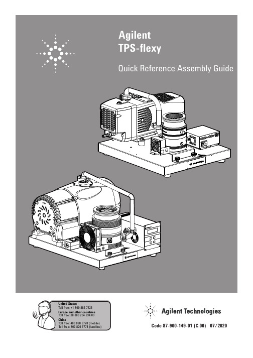
8
Note:
9
Note:
10
Agilent TPS-flexy
Quick Reference Assembly Guide
United States Agilent Technologies 121 Hartwell Avenue, Lexington MA 02421, USA Tel: +1 781 861 7200, Fax: +1 781 860 5437 Toll free: +1 800 882 7426 Europe and other countries Agilent Technologies Italia SpA via F.lli Varian 54, 10040 Leini, (Torino), Italy Tel: +39 011 9979 111, Fax: +39 011 9979 350 Toll free: 00 800 234 234 00 China Agilent Technologies Co. Ltd. No.3, Wang Jing Bei Lu, Chao Yang District, Beijing, 100102, China Tel: +86 (0) 10 64397888, Fax: +86 (0) 10 64392765 Toll free: 400 820 6778 (mobile) Toll free: 800 820 6778 (landline) This information is subject to change without notice. © Agilent Technologies, Inc. 2020
- 1、下载文档前请自行甄别文档内容的完整性,平台不提供额外的编辑、内容补充、找答案等附加服务。
- 2、"仅部分预览"的文档,不可在线预览部分如存在完整性等问题,可反馈申请退款(可完整预览的文档不适用该条件!)。
- 3、如文档侵犯您的权益,请联系客服反馈,我们会尽快为您处理(人工客服工作时间:9:00-18:30)。
Installation GuideRack Mount KitsFor rack mounting Agilent 86120A/B/C instruments.2© Copyright 2000Agilent Technologies All Rights Reserved. Repro-duction, adaptation, or trans-lation without prior written permission is prohibited, except as allowed under copy-right laws.Agilent Part No. 5962-5931Printed in USA February 2000Agilent Technologies Lightwave Division 1400 Fountaingrove Parkway Santa Rosa, CA 95403-1799, USA (707) 577-1400Notice.The information contained in this document is subject tochange without notice. Com-panies, names, and data used in examples herein are ficti-tious unless otherwise noted. Agilent Technologies makes no warranty of any kind with regard to this material, includ-ing but not limited to, the implied warranties of mer-chantability and fitness for a particular purpose. Agilent Technologies shall not be lia-ble for errors contained herein or for incidental or conse-quential damages in connec-tion with the furnishing, performance, or use of this material.Restricted Rights e, duplication, or disclo-sure by the U.S. Government is subject to restrictions as set forth in subparagraph (c) (1) (ii) of the Rights in Technical Data and Computer Software clause at DFARS 252.227-7013 for DOD agencies, and sub-paragraphs (c) (1) and (c) (2) of the Commercial Computer Software Restricted Rights clause at FAR 52.227-19 for other agencies.Warranty.This Agilent Technologies instrument product is war-ranted against defects in material and workmanship for a period of one year from date of shipment. During the war-ranty period, Agilent Technol-ogies will, at its option, either repair or replace products which prove to be defective.For warranty service or repair, this product must be returned to a service facility desig-nated by Agilent Technolo-gies. Buyer shall prepayshipping charges to Agilent Technologies and Agilent Technologies shall pay ship-ping charges to return the product to Buyer. However, Buyer shall pay all shipping charges, duties, and taxes forproducts returned to Agilent Technologies from another country.Agilent Technologies war-rants that its software and firmware designated by Agi-lent Technologies for use with an instrument will execute its programming instructions when properly installed on that instrument. Agilent Tech-nologies does not warrant that the operation of the instru-ment, or software, or firmwarewill be uninterrupted or error-free. Limitation of Warranty.The foregoing warranty shall not apply to defects resulting from improper or inadequate maintenance by Buyer, Buyer-supplied software or interfac-ing, unauthorized modifica-tion or misuse, operation outside of the environmental specifications for the product, or improper site preparation or maintenance.No other warranty is expressed or implied. Agilent Technologies specifically dis-claims the implied warranties of merchantability and fitnessfor a particular purpose.Exclusive Remedies.The remedies provided herein are buyer's sole and exclusiveremedies. Agilent Technolo-gies shall not be liable for any direct, indirect, special, inci-dental, or consequential dam-ages, whether based on contract, tort, or any other legal theory.Safety Symbols.CAUTION The caution sign denotes ahazard. It calls attention to aprocedure which, if not cor-rectly performed or adhered to, could result in damage to or destruction of the product. Do not proceed beyond a cau-tion sign until the indicated conditions are fully under-stood and met.WARNING The warning sign denotes a hazard. It calls attention to a procedure which, if not cor-rectly performed or adhered to, could result in injury or loss of life. Do not proceed beyond a warning sign until the indicated conditions are fully understood and met.The instruction man-ual symbol. The prod-uct is marked with this warning symbol when it is necessary for the user to refer to the instructions in the manual.The laser radiation symbol. This warning symbol is marked on products which have a laser output.The AC symbol is used to indicate the required nature of the line module input power. |The ON symbols are used to mark the posi-tions of the instrument power line switch. ❍The OFF symbols are used to mark the positions of the instru-ment power line switch.The CE mark is a reg-istered trademark ofthe European Commu-nity.The CSA mark is a reg-istered trademark of the Canadian Stan-dards Association.The C-Tick mark is a registered trademarkof the Australian Spec-trum Management Agency.This text denotes theinstrument is anIndustrial Scientific and Medical Group 1 Class A product.Typographical Conven-tions.The following conventions are used in this book:Key type for keys or text located on the keyboard or instrument.Softkey type for key names that are displayed on the instru-ment’s screen.Display type for words or characters displayed on the computer’s screen or instru-ment’s er type for words or charac-ters that you type or enter.Emphasis type for words or characters that emphasize some point or that are used asplace holders for text that youtype.ISM1-A3General Safety Considerations General Safety ConsiderationsW A R N I N G There are many points in the instrument which can, if contacted, cause personal injury. Be extremely careful.W A R N I N G These servicing instructions are for use by qualified personnel only. To avoid electrical shock, do not perform any servicing unless you are qualified to do so.W A R N I N G The opening of covers or removal of parts is likely to expose dangerous voltages. Disconnect the instrument from all voltage sources while it is being opened.W A R N I N G The power cords on instruments are connected to internal capacitors that may remain live for five seconds after disconnecting the plug from its power supply.W A R N I N G To avoid exposure to the laser path of a CLASS IIIa LASERPRODUCT, do not open the A1A1, A1A2, or A1A3 assemblies. There are no serviceable components inside. Laser pathsoutside of the A1A1, A1A2, or A1A3 assemblies do not require precautions to maintain ser classificationThe Agilent 86120A/B/C is classified as an FDA LASER Class 1 product according to 21CFR1040.10 and IEC Laser Class 1 according to IEC 60825.The total power of light energy radiated out of the OPTICAL OUT connector is no greater than +8.1 dBm (6.5mW). Operator maintenance or precautions are not necessary to maintain safety. No operator accessible controls, adjustments, or performance of proce-dures result in hazardous radiation exposure.4General Safety ConsiderationsC A U T I O N Do not disturb any of the screws on the A1A1, A1A2, or A1A3 assemblies.Loosening or tightening these screws destroys the amplitude and wavelength calibration so that the Agilent 86120A/B/C no longer meets its published specifications. If the position of these screws is changed, return the instrument to Agilent Technologies for service.This product has been designed and tested in accordance with IEC Publica-tion 1010, Safety Requirements for Electronic Measuring Apparatus, and has been supplied in a safe condition. The instruction documentation contains information and warnings which must be followed by the user to ensure safe operation and to maintain the product in a safe condition.W A R N I N G If this instrument is not used as specified, the protection provided by the equipment could be impaired. This instrument must be used in a normal condition (in which all means for protection are intact) only.W A R N I N G To prevent electrical shock, disconnect the Agilent 86120A/B/C frommains before cleaning. Use a dry cloth or one slightly dampened with water to clean the external case parts. Do not attempt to clean internally.W A R N I N G This is a Safety Class 1 product (provided with a protective earthingground incorporated in the power cord). The mains plug shall only beinserted in a socket outlet provided with a protective earth contact.5General Safety ConsiderationsAny interruption of the protective conductor inside or outside of the product is likely to make the product dangerous. Intentional interruption is prohibited.W A R N I N G No operator serviceable parts inside. Refer servicing to qualified personnel. To prevent electrical shock, do not remove covers.W A R N I N G For continued protection against fire hazard, replace line fuse onlywith same type and ratings, (type T 0.315A/250V for 100/120Voperation and 0.16A/250V for 220/240V operation). The use of other fuses or materials is prohibited. Verify that the value of the line-voltage fuse is correct.•For 100/120V operation, use an IEC 127 5×20 mm, 0.315 A, 250 V, Agilent Technologies part number 2110-0449.•For 220/240V operation, use an IEC 127 5×20 mm, 0.16 A, 250 V, Agilent Technologies part number 2110-0448.C A U T I O N Before switching on this instrument, make sure that the line voltage selector switch is set to the line voltage of the power supply and the correct fuse is installed. Assure the supply voltage is in the specified range.C A U T I O N This product is designed for use in Installation Category II and PollutionDegree 2 per IEC 1010 and 664 respectively.C A U T I O N VENTILATION REQUIREMENTS: When installing the product in a cabinet, theconvection into and out of the product must not be restricted. The ambient temperature (outside the cabinet) must be less than the maximum operating temperature of the product by 4°C for every 100 watts dissipated in thecabinet. If the total power dissipated in the cabinet is greater than 800watts, then forced convection must be used.C A U T I O N Always use the three-prong ac power cord supplied with this instrument. Failure to ensure adequate earth grounding by not using this cord may cause instrument damage.C A U T I O N Do not connect ac power until you have verified the line voltage is correct. Damage to the equipment could result.C A U T I O N This instrument has autoranging line voltage input. Be sure the supply voltageis within the specified range.6IntroductionIntroductionThe installation instructions in this book apply to the following kits:•Rack-mount kit, 86120-60030•Rack-mount kit with handles, 86120-60031•Rack-slide kit, 1494-0059These kits mount 4.5-inch instruments into a rack with 482.6 mm (19 inch) spacing. For a list of parts contained in the kits, refer to “Replacement Parts ” on page 19.C A U T I O N When installing the rack-mount kits, the instrument ’s cover must betemporarily removed. Because this exposes the internal circuits to electrostatic discharge, perform the procedure at a static-safe workstation. Refer to “Electrostatic Discharge Information ” on page 21.Required Tools The following tools are needed to assemble the rack- mount kits. If a 7 mm nutdriver is unavailable, the needle-nose pliers may be substituted.#1 pozidrive screwdriver#2 pozidrive screwdriver4 mm hex key (included with kit)7 mm nut driver (preferred) or needle-nose pliers5.5 mm nut driver (preferred) or needle-nose pliersT-6 TORX driverT-10 TORX driver, right angle (included with kit)T-15 TORX driverFor any assistance, contact your nearest Agilent Technologies Sales and Ser-vice Office. Refer to “Agilent Technologies Service Offices ” on page 23.7Introduction Contents To Rack Mount the Instrument 8To Install the Rack-Slide Kit 17Replacement Parts 19Electrostatic Discharge Information 21Agilent Technologies Service Offices 238To Rack Mount the InstrumentTo Rack Mount the InstrumentPlease observe the following. Circled numbers in this procedure refer to items shown in figures. Agilent Technologies part numbers are listed in parenthesis. You will find these part numbers listed on the bags that contain the parts.W A R N I N G The opening of covers or removal of parts is likely to expose dangerous voltages. Disconnect the instrument from all voltage sources while it is being opened.1Disconnect the power cord from the instrument.2Place the instrument face down as illustrated in Figure 1.3Remove the eight screws (four per side) securing the front bumpers ➁ to the instrument.4Remove the two screws securing the handle, and remove the handle.5Use a 4 mm hex key (8710-1755) to loosen the four screws ➂ in the rear feet to disengage the cover assembly ➀ from the instrument.C A U T I O N Beneath the cover, located in the vicinity of the handle attachment screws, aretwo finger springs that reduce electro-magnetic interference (EMI). These springs can be damaged. To avoid damage, perform the following steps carefully to remove the cover.6Located the side of the instrument opposite to where the handles were attached. While applying pressure to this side, simultaneously pull on the instrument foot that is located on the side where the handle was attached. This action relieves strain on the springs while removing the cover.9To Rack Mount the Instrument.Figure 1.Preparing the cover assembly7Slide the instrument cover assembly toward the rear of the instrument, andremove the cover from the instrument.8Remove the two screws ➃ that attach the rear feet to the cover assembly, andremove the feet. These screws are located inside the cover.9Remove the six screws that secure the two bottom tilt-stand feet, and removethe feet. The screws are located inside the cover. Use the T-10 right-angle TORX key included with the kit.C A U T I O N Be careful to protect the instrument ’s cable assemblies and components fromdamage when you replace the cover assembly. Use key caution to avoid damaging the EMI springs. If you damage an EMI spring, you can order a new one using Agilent Technologies part number 8160-0656.10Slide the cover assembly back onto the instrument chassis while applyingpressure to the side of the cover that is opposite the handle attachment points. Gentle pressure ensures that the cover will not bind against the EMI springs.Make sure that the seam in the cover is located on the bottom of the instru-10To Rack Mount the Instrument ment.C A U T I O N Make sure that the instrument ’s cover properly engages the gasket in theinstrument ’s front frame.11Onto each of the four socket-head cap screws (0515-0049), place a split-lockwasher (2190-0587) and a flat washer (3050-0894).12Use these screws to temporarily attach the instrument ’s cover.13Locate the rack-mount kit ’s rear support ➁ (5002-0634) and rear frame ➀(5021-5804) as illustrated in Figure 2.The text “METRIC ” on the frame and the two adjacent holes illustrated in the figure identify the top sides. This orientation ensures that the top of the frame and the top of the rear support are joined correctly.Figure 2.Assembling the rack’s rear frame14Position the rear support ’s studs into the corresponding top row of holes in therear frame.15Slightly squeeze the rear support until the bottom row of studs clears the rearframe and insert into the bottom row of holes. Fasten with eight nuts ➂ (0535-0031). Alternately tighten each nut to the recommended torque of 6inch-pounds.16Attach the four side struts (5021-5837) to the rack ’s rear frame using eightscrews ➀(0515-1331). See Figure 3.11To Rack Mount the InstrumentFigure 3.Attaching the side struts17Connect the two front mounting brackets ➀ (5002-0633) to the instrument ’s front frame using four pan-head screws ➂ (0515-1079). See Figure 4. Tighten each screw to a torque of 6 inch-pounds.18Locate the kit ’s front frame (5021-8403). Look into the frame as if you were looking into the front of an instrument. Find the two vent holes which are about half an inch long and a quarter of an inch high. When the frame is installed,these holes must be oriented along the bottom of the instrument.12To Rack Mount the InstrumentFigure 4.Attaching the mounting brackets19Slide the kit ’s front frame ➀ over the rear of the instrument until it is over theinstrument ’s front frame. See Figure 5.20Attach the frame to the front brackets using four flat-head screws ➁ (0515-1234).21Place the dress panel ➂ (5002-0640) over the instrument ’s front panel. Securewith four nuts ➃ (0535-0082) tightened to a torque of 6 inch-pounds.If you do not have a 7 mm nut driver, use the spring clips rather than the six nuts. Apply the spring clips to the dress panel studs using needle-nose pliers.C A U T I O NDo not over torque the nuts.13To Rack Mount the InstrumentFigure 5.Attaching the front22Place the instrument on its front frame.C A U T I O N Avoid damaging the instrument ’s front panel and input connector by placing itonto a surface protected by cloth.23Remove the four socket-head cap screws that secure the instrument ’s cover.Do not remove the cover. You attached these screws in Step 12.24Place the rack-mount kit frame onto the instrument as shown in Figure 6.14To Rack Mount the InstrumentFigure 6.Attaching the rack frame25Secure the four side struts to the front frame using eight screws ➀(0515-1331). Torque the screws to 12 inch-pounds.26Use the four socket-head cap screws ➀ removed in Step 23 to secure theinstrument ’s cover as shown in Figure 7.15To Rack Mount the InstrumentFigure 7.Securing the frame27Place the instrument in its operating position. See Figure 8.28If you are installing the rack-mount kit with handles (5062-3983), mount thehandles ➀ and rack flanges ➁ to the rack frame using six pan-head screws ➂.Tighten each screw to a torque of 12 inch-pounds.16To Rack Mount the InstrumentFigure 8.Attaching the flanges and handles29If your installing the rack-mount kit without handles (5062-3977), mount rackflanges ➁ directly to the rack frame using six pan-head screws ➂. Tighten each screw to a torque of 12 inch-pounds.30The instrument is now ready to mount into the system rack.W A R N I N G If an instrument handle is damaged, it should be replaced immediately. Damaged handles can break while the instrument is being moved orlifted. This may cause damage to the instrument or personal injury.17To Install the Rack-Slide KitTo Install the Rack-Slide Kit1Install the rack-mount kit as described in “To Rack Mount the Instrument ” on page 8.2Expand each rack slide to its full length.Note that Figure 9 does not show the rack slide extended to its full length.Figure 9.Installing rack slides3Separate the inner slide member ➀ from the outer slide member ➁ by pressing the release button located on the inner slide member.4Pull the inner slide member out of the assembly.5Attach an inner slide member to each side of the rack-mount frame using four18To Install the Rack-Slide Kit(two per side) M5 × 0.8 × 14 mm pan-head screws ➂.6Insert two unistrut nuts ➃ in each of the four vertical columns of the systems rack.7Compress each outer-slide member to its shortest length, revealing the holes ➄ for screws ➅. If necessary, press the release button ➆.8Attach an outer slide member to each side of the systems rack, using two M4 × 0.7 × 12 mm flat-head screws ➅ in the front and two M4 × 0.7 × 12 mm pan-head screws ➇ in the rear.9Place the instrument into the rack by sliding the inner slide members into the outer slide members. Use the release buttons, located on the slides, to enable complete compression of the slides.10To prevent the rack slides from accidentally opening, use screws to secure the rack frame to the system cabinet.19Replacement PartsReplacement PartsTable-1. Rack-Mount Kits (86120-60030 and 86120-60031)Agilent Part Number Quantity Description5062-39831Front-handle kit (with handles). Supplied with 86120-60031 kit.5062-39771Front-handle kit (without handles). Supplied with 86120-60030 kit.8710-17551Hex Key, 4mm8710-16571T10 right-angle TORX key5002-06401Dress Panel5021-84031Front Frame5002-06332Front Bracket5002-06341Rear Support5021-58041Rear Frame5021-58374Side Strut0535-00318Nut M3 × 0.5mm0535-00824Nut M4 × 0.7mm2190-05874Lock Washer M5.0 ID3050-08944Flat Washer M5.0 ID0510-11486Push-On Retainer Clips0515-00494Screw, Socket-Head M5 × 0.8 × 12 mm-LG0515-10794Screw, Mach M3 × 0.5 8 mm-LG PAN-HD0515-12344Screw, Mach M3.5 × 8 mm-LG FLAT-HD0515-133116Screw, Mach M4 × 0.7 6 mm-LG FLT-HD20Replacement PartsTable-2. Rack Slide Kit (Agilent part number 1494-0059)Agilent Part NumberQuantity Description —2Slides (not sold separately)0515-09494Screw, Mach M5 × 0.8 14 mm-LG PAN-HD 0515-10134Screw, Mach M5 × 0.7 12 mm-LG FLAT-HD 0515-09094Screw, Mach M4 × 0.7 12 mm-LG PAN-HD 0535-00808Unistrut Nut M4 × 0.721Electrostatic Discharge InformationElectrostatic Discharge InformationElectrostatic discharge (ESD) can damage or destroy electronic components.All work on electronic assemblies should be performed at a static-safe workstation. The following figure shows an example of a static-safe work stationusing two types of ESD protection:•Conductive table-mat and wrist-strap combination.•Conductive floor-mat and heel-strap combination.22Electrostatic Discharge InformationBoth types, when used together, provide a significant level of ESD protection.Of the two, only the table-mat and wrist-strap combination provides adequateESD protection when used alone.To ensure user safety, the static-safe accessories must provide at least 1 M Ω ofisolation from ground. Refer to Table 3 on page 22 for information on ordering static-safe accessories.W A R N I N G These techniques for a static-safe work station should not be used when working on circuitry with a voltage potential greater than 500volts.The following suggestions may help reduce ESD damage that occurs duringtesting and servicing operations.•Personnel should be grounded with a resistor-isolated wrist strap before re-moving any assembly from the unit.•Be sure all instruments are properly earth-grounded to prevent a buildup ofstatic charge.Table 3 on page 22 lists static-safe accessories that can be obtained from Agi-lent Technologies using the Agilent part numbers shown.Table-3. Static-Safe AccessoriesAgilent PartNumber Description9300-0797Set includes: 3M static control mat 0.6 m × 1.2 m (2 ft × 4 ft) and 4.6 cm (15 ft) ground wire. (The wrist-strap and wrist-strap cord are not included. They must be ordered separately.)9300-0980Wrist-strap cord 1.5 m (5 ft)9300-1383Wrist-strap, color black, stainless steel, without cord, has four adjustable links and a 7 mm post-typeconnection.9300-1169ESD heel-strap (reusable 6 to 12 months).23Agilent Technologies Service OfficesAgilent Technologies Service OfficesBefore returning an instrument for service, call the Agilent TechnologiesInstrument Support Center at (800) 403-0801, visit the Test and Measurement Web Sites by Country page at /tmo/country/English/index.html, or call one of the numbers listed below.Agilent Technologies Service Numbers Austria 01/25125-7171Belgium 32-2-778.37.71Brazil (11) 7297-8600China 86 10 6261 3819Denmark 45 99 12 88Finland 358-10-855-2360France 01.69.82.66.66Germany 0180/524-6330India 080-34 35788Italy +39 02 9212 2701Ireland01 615 8222Japan (81)-426-56-7832Korea 82/2-3770-0419Mexico (5) 258-4826Netherlands 020-547 6463Norway 22 73 57 59Russia+7-095-797-3930Spain (34/91) 631 1213Sweden08-5064 8700Switzerland (01) 735 7200United Kingdom 01 344 366666United States(800) 403-080124Agilent Technologies Service Offices。