SMDK6400_6410_Linux_2.6.21_RTC_Porting_Guide_REV1.00_20070710
uboot移植到6410开发板的过程及环境变量的修改

天涯海阁嵌入式linuxu boot移植到6410开发板的过程及环境变量的修改分类: uboot 2012-09-28 11:16 319人阅读 评论(0) 收藏举报一、通过U盘下载uboot.bin到开发板,U盘事先必须用飞凌光盘里的一个快速烧写工具,把mmc.bin烧写进U盘内,但是打开U盘后看不到这个文件。
然后将uboot.bin烧写进U盘。
(ps,如果要直接通过U盘将内核还有文件系统烧写进开发板里,可以直接将zImage跟cramfs文件系统拷进U盘)二、将U盘插入开发板,选择U盘启动模式,1 2 3 off ,其他on;打开终端,启动;之后就开始烧写,由于没有在U 盘内放zImage ,所以烧写的最后一行会提示not found zImage 等。
三、断开电源,选择nand flash启动:1 2 3 6 7 off,其他on;打开电源,在bootdelay计时的时候按下空格键;进入uboot的命令模式;四、查看环境变量:printenv五、修改环境变量:setenv,包括ip地址等,主要是修改bootcmd跟bootargs,我是用tftp下载uImage,用nfs挂载根文件系统:Setenv bootcmd 'tftp c0008000 uImage;bootm c0008000'(如果要设置多个,就要加上''号,如果有多个命令,在两个命令之间加;号)Setenv bootargs ‘console=ttySAC0 root=/dev/nfs nfsroot=172.22.17.20:/nfsroot/rootfsip=172.22.17.21’(consle是设置平台,nfsroot 是设置nfs的挂载地址,172.22.17.21是开发板的ip,172.22.17.20是主机的ip)都设置完再查看环境变量printenv ,如果没问题就保存:saveenv六、重启 ok**************************************************************************************************** 下面对bootargs的设置做一些介绍:bootargs是环境变量中的重中之重,甚至可以说整个环境变量都是围绕着bootargs来设置的。
tiny6410内核移植

Tiny6410 的内核移植(拿来主义)一、开发环境宿主机: vista+VMware+ fedoral13(win7下虚拟机)编译器: 友善自带arm-linux-gcc-4.5.1-v6-vfp-20101103.tgz开发板: tiny6410,核心板号1106 NAND 2G RAM 256M注意:移植内核时,确保引导文件为u-boot类型,否则到后面下载到开发板使会出现乱码以及不必要的错误二、移植nand_flash1 下载linux-2.6.38的源码ftp:///pub/linux/kernel/v2.6/linux-2.6.38.tar.bz22 解压#tar xvfj /mnt/ubuntu/linux-2.6.38.tar.bz2 -C .3 修改根下的Makefile#vi Makefile191行改为ARCH ?= armCROSS_COMPILE ?= arm-linux- (找到其交叉编译环境)4 生成默认配置文件#cp arch/arm/configs/s3c6400_defconfig .config(如果省略的话,后面会找不到System Type)5 修改配置项(基本配置)#make menuconfigGeneral setup->(/usr/4.5.1/bin/arm-linux-) Cross-compiler tool prefix 我将编译器解压到了/opt/Friendly/toolschain/4.5.1/bin目录(如果第三步中以修改“plier ? = arm-linux- ”此项,这步可以不作)System Type->[*] MINI6410 选上,其他的可以去掉,不确定的可以参考友善之臂的(这样编译出来的内核是可以被uboot引导的,然后是增加nand flash支持)vi arch/arm/mach-s3c64xx/mach-mini6410.c第117行struct mtd_partition mini6410_nand_part[] = {{.name = "Bootloader",.offset = 0,.size = (4 * 128 *SZ_1K),.mask_flags = MTD_CAP_NANDFLASH,},{.name = "Kernel",.offset = (4 * 128 *SZ_1K),.size = (5*SZ_1M) ,.mask_flags = MTD_CAP_NANDFLASH,},{.name = "File System",.offset = MTDPART_OFS_APPEND,.size = MTDPART_SIZ_FULL,}}; //update at 2011-8-26 经过测试发现,这里改完后根本不起作用,甚至将整个注释也无妨,估计分区已经固死在后面的s3c_nand_mlc.fo 中6 拷贝NAND FLASH驱动(将6410内核中的如下文件拷到相应的目录下)需拷贝文件:drivers/mtd/nand/s3c_nand.carch/arm/plat-samsung/include/plat/regs-nand.h 覆盖掉drivers/mtd/nand/s3c_nand_mlc.fo《s3c_nand_mlc.fo友善没有开源的一个驱动之一,所以不用研究了,拷过来就是了。
Linux字符设备驱动之Tiny6410 LED驱动编写

Linux字符设备驱动之Tiny6410 LED驱动分析摘要:驱动程序是应用程序和底层硬件之间的桥梁,非常重要。
字符设备是一种可以当做一个字节流来存取的设备,这样的设备只能一个字节一个字节的进行数据传输,这样的驱动常常至少实现open、close、read、和write系统条用,常见的有串口、LED、文本控制台等,字符设备通过文件系统节点来存取,例如/dev/tty1和/dev/lp0.在一个字符设备和一个普通文件之间唯一相关的不同就是,你可以在普通的文件中移来移去,但是大部分字符社诶仅仅是数据通道,只能顺序存取。
重要概念1.用户空间和内核空间一个驱动模块在内核空间运行,而应用程序则是在用户空间运行,这个概念是操作系统的理论基础。
Linux为这两种空间之间的数据传输定义了两个函数,分别为copy_to_user()和copy_from_user(),从字面意思可以知道函数的意义。
比如在编写驱动程序时,很显然驱动程序属于内核空间,会经常使用copy_from_user()函数,从应用程序中获取数据给驱动程序。
2.编译模块使用make xxxx modules 生成xxx.ko模块。
3.加载和卸载模块(驱动)驱动生成的模块需要加载到内核中,加载模块使用insmod指令,如:insmodxxx.ko卸载驱动则用rmmod命令。
4.所需头文件#include <linux/module.h> //包含大量加载模块所需的函数和符号定义#include<linux/init.h> //制定初始化和清理函数许可凭证指令:MODULE_LICENSE(“GPL”);5.初始化和关停初始化指令:static int __initinitialization_function(void){}module_init(initialization_function);初始化函数应声明为静态,因为他们不会再特定文件之外可见,毕竟static的重点应用是“隐藏”。
Linux lcd驱动分析
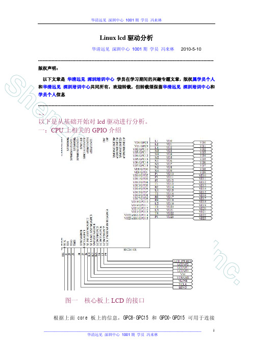
CPU
zh e
lcd GPIO
n
Fa
rs
ig
ht
In
1
c.
LCD
core GPC8-GPC15 GPD0-GPD15
__________________________________________________________________________ 1001
1001
VD[0:23] GPDX
rs
ig
HSYNC
ht
239
(VSPW+1)
VSPW+1+VBPD+1
In
9
c.
HSYNC HSPW HSYNC HSYNC+1 VCLK
__________________________________________________________________________ 1001
1001
__________________________________________________________________________ 1001
1001
TFT HSYNC VCLK
VSYNC HSYNC VDEN
VSYNC
1
Sh
VSYNC VSPW+1 VBPD+1 CRT TFT WXCAT35-TG3#001F 3.5 TFT VFPD +1 CRT LCD HSYNC
1001
Sh
en
fbmem.c FrameBuffer
zh e
fbmem.c FrameBuffer
3.1
FrameBuffer
n
Mini6410上最简单的LED点灯裸机程序
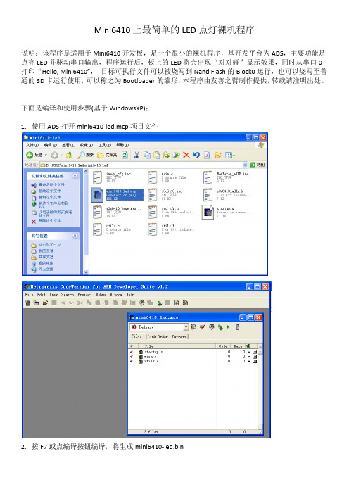
Mini6410上最简单的LED点灯裸机程序说明:该程序是适用于Mini6410开发板,是一个很小的裸机程序,基开发平台为ADS,主要功能是点亮LED并驱动串口输出,程序运行后,板上的LED将会出现“对对碰”显示效果,同时从串口0打印“Hello, Mini6410”, 目标可执行文件可以被烧写到Nand Flash的Block0运行,也可以烧写至普通的SD卡运行使用,可以称之为Bootloader的雏形,本程序由友善之臂制作提供,转载请注明出处。
下面是编译和使用步骤(基于WindowsXP);1.使用ADS打开mini6410‐led.mcp项目文件2.按F7或点编译按钮编译,将生成mini6410‐led.bin编译结果:最后生成mini6410‐led.bin3.烧写到Nand Flash运行要把mini6410‐led.bin烧写到Nand Flash,需要借助已经安装了Superboot的SD卡,步骤如下:把mini6410‐led.bin拷贝到SD卡的images目录下打开FriendlyARM.ini配文件,修改如下关键定义:Action=installOS= UserBinUserBin‐Image=mini6410‐led.bin4.下载到内存中运行借助已经安装了SuperbootSD卡,可以把把mini6410‐led.bin加载到内存中运行,步骤如下: 把mini6410‐led.bin拷贝到SD卡的images目录下,打开FriendlyARM.ini配文件,修改如下关键定义:Action=runOS= UserBinUserBin‐Image=mini6410‐led.binUserBin‐StartAddress=50000000附1:串口输出结果:附2: mini6410‐led主体程序代码:#include "utils.h"static void LedDelay(void){volatile unsigned int k;for(k = 0; k < 20000000; k++);}int main(void){Uart_Init();Port_Init();Uart_SendString("\r\nHello, Mini6410\r\n");for(;;) {Led_Display(0x9); // 1001 LedDelay();Led_Display(0x6); // 0110 LedDelay();}return 0;}。
linux26221的在s3c2410板子上的移植

linux26221的在s3c2410板子上的移植----------------------------------------------bootloader编译环境:vivi版本:0.1.4交叉编译器(CROSS-COMPILE)版本:2.95.3(下载地址略:网上专门多搜下。
)操作系统:redhat server 5======================================linux内核编译环境:内核版本:linux2.6.22.2交叉编译器:自己做的适合Linux2.6.22.2版本的交叉编译器操作系统:redhat server 5======================================文件系统编译环境:busybox1.5.1,或1.4.2交叉编译器(CROSS-COMPILE)版本:同上操作系统:redhat server 5----------------------------------------------硬件:自己做的2410开发板内存:64MB SDRAM(2×16M×16位);CPU:S3C2410 ARM处理器,Nor Flash:2MB的Nor Flash,用于固化测试程序(用来下载bootloader,内核,或文件系统);NANDflash: 64MB的Nand Flash,用于储备Bootloader、Linux内核及文件系统、应用程序和数据;++++++++++++++++++++++++++++++++++++++++++++++====================================================================== ============================一:编译环境搭建====================================================================== ============================一:搭建交叉编译环境讲明:由于编译交叉编译环境比较繁琐,建议大伙儿用差不多编译好的交叉编译环境。
飞凌ok6410定时器精确控制led

飞凌ok6410定时器精确控制led关于借鉴与原创安全的说明:飞凌提供的代码有一定问题,并且部分关键代码没有解释,我在搜集各方面资料后综合网友指正和自己的理解,注释了部分自己认为重要的部分。
当然如果大神觉得可不注释,也可以。
此篇文章援引多家大神的微博,如需看大神原作,请百度搜索标题,此处个人见解不恰当的请各位指正。
6410 中的PWM 定时器1.简单介绍:S3C6410X 中有5 个定时器,这些定时器产生内部中断。
其中,Timer0 和Timer1 具有PWM 功能,而Timer2,3,4 没有此功能。
PWM 具有两种操作模式:自动装载模式,一次触发模式。
为实现PWM 功能,芯片提供了16 个功能寄存器。
这些功能寄存器都连接APB 总线。
定时器具有双缓冲特性,这样就能在不停止当前定时器操作的情况下,为下次定时器运行装入新的数值。
尽管为定时器设置了新数值,但当前的定时操作能够成功完成。
定时器从TCNTBn 读取的值是为下次延时定时用的,并不影响当前定时器的运行。
当TCNTn 减小到0 的时候,TCNTBn 的值会自动复制到TCNTn 中,这就是说的自动装载操作。
定时器的当前计数值可以从定时计数观察寄存器中TCNTOn 读取。
如果TCNTn 为0 且从装载也为0 的话则TCNTn不在进行下次操作。
2.定时器的电路结够图:3.定时器架构流程。
PCLK ---à 经过8 位的预分频器【8bit prescaler0】--à 分频器divider [1/1 1/2 1/4 1/81/16] -à 多路选择器MUX -à 逻辑控制器。
〖Linux〗OK6410a蜂鸣器的驱动程序编写全程实录
〖Linux〗OK6410a蜂鸣器的驱动程序编写全程实录最近在看⼀本书,受益匪浅,作者是李宁,下边是编写本次蜂鸣器的全程实录:1. 了解开发板中的蜂鸣器 1) 查看蜂鸣器buzzer在底板中的管脚信息 2) 查看蜂鸣器在总线中的信息 3) 翻看S3C6410芯⽚⼿册,查看GPF15相关信息2. 在了解了开发板中蜂鸣器之后,编写代码对它进⾏控制。
由于蜂鸣器是通过PWM(脉冲宽度调制)进⾏开关控制的,故也称为PWM。
1) 编写pwm.c(包含Linux驱动模块的主要模型代码)#include "pwm_fun.h"static struct semaphore lock; /* 创建信号量*///⽂件打开时,⾃动操作此函数,使⽤信号量控制其访问static int s3c6410_pwm_open(struct inode *inode, struct file *file){if (!down_trylock(&lock)) /* 使⽤信号量控制只能由⼀个进程打开 */{return0;}else{return -EBUSY;}}//⽂件关闭时,⾃动操作此函数,使⽤信号量控制其访问static int s3c6410_pwm_close(struct inode *inode, struct file *file){up(&lock); /* 释放信号量 */return0;}//⽂件中关于ioctl的操作static long s3c6410_pwm_ioctl(struct file *filep, unsigned int cmd, unsigned long arg){switch ( cmd ) {case PWM_IOCTL_START:pwm_start();break;case PWM_IOCTL_STOP:pwm_stop();break;default:break;} /* ----- end switch ----- */return0;}//⽂件操作的指针static struct file_operations dev_fops = {.owner = THIS_MODULE,.open = s3c6410_pwm_open,.release = s3c6410_pwm_close,.unlocked_ioctl = s3c6410_pwm_ioctl,};//设备的属性static struct miscdevice misc = {.minor = MISC_DYNAMIC_MINOR,.name = DEVICE_NAME,.fops = &dev_fops,};//驱动的⼊⼝函数static int __init dev_init(void){int ret;init_MUTEX(&lock); /* 初始化信号量 */ret = misc_register(&misc);printk(DEVICE_NAME"\tinitialized\n");return ret;}//驱动的退出函数static void __exit dev_exit(void){misc_deregister(&misc);printk(DEVICE_NAME"\texited\n");}module_init(dev_init);module_exit(dev_exit); 2) 编写pwm_fun.c(包含对蜂鸣器控制的主要代码)#include "pwm_fun.h"void pwm_start(void){unsigned int tmp;tmp = ioread32(S3C64XX_GPFCON);tmp &= ~(0x3U<<30); /* 最⾼两位清零,保留其他位 */tmp |= (0x2U<<30); /* 最⾼两位设置为10,蜂鸣器发出尖叫声 */iowrite32(tmp, S3C64XX_GPFCON);}void pwm_stop(void){unsigned tmp;tmp = ioread32(S3C64XX_GPFCON);tmp &= ~(0x3U<<30); /* 最⾼两位清零,蜂鸣器停⽌尖叫 */iowrite32(tmp, S3C64XX_GPFCON);} 3) 编写pwm_fun.h(包含⼀些必须的头⽂件及宏定义信息)#include <linux/module.h>#include <linux/kernel.h>#include <linux/fs.h>#include <linux/init.h>#include <asm/io.h>#include <linux/interrupt.h>#include <linux/device.h>#include <asm/uaccess.h>#include <linux/miscdevice.h>#include <mach/map.h>#include <mach/regs-clock.h>#include <mach/regs-gpio.h>#include <mach/gpio-bank-f.h>#include <mach/gpio-bank-k.h>#define DEVICE_NAME "pwm_dev"#define PWM_IOCTL_START 1#define PWM_IOCTL_STOP 0extern void pwm_start(void);extern void pwm_stop(void); 4) 编写Makefile⽂件(使编译过程⾃动完成)obj-m := pwm_driver.opwm_driver-objs := pwm.o pwm_fun.oPWD := $(shell pwd)CROSS_COMPILE ?= arm-none-linux-gnueabi-CC := $(CROSS_COMPILE)gccCFLAGS += -staticKPATH := /media/Source/Forlinx/android2.3_kernel_v1.01all: ioctlmake -C $(KPATH) M=$(PWD) modulesioctl: ioctl.c$(CC) $(CFLAGS) $^ -o $@clean:rm -rf *.o *.ko *.mod.c Module.* modules.* ioctl 5) 编写测试程序ioctl(⽤于对驱动程序的测试)#include <fcntl.h>#include <stdio.h>#include <stdlib.h>#include <unistd.h>#include <sys/ioctl.h>/** === FUNCTION ====================================================================== * Name: main* Description: 对驱动程序进⾏测试* ===================================================================================== */int main ( int argc, char *argv[] ){int file_handler = 0;int cmd = 0;int arg = 0;if (argc < 4){printf("Usage: ioctl <DEVICE_NAME> <cmd> <arg>\n");return EXIT_FAILURE;}cmd = atoi(argv[2]);arg = atoi(argv[3]);printf("dev:%s\n", argv[1]);printf("cmd:%d\n", cmd);printf("arg:%d\n", arg);file_handler = open(argv[1], 0);if (file_handler<0){printf("open %s failure.\n", argv[1]);}ioctl(file_handler, cmd, arg);close(file_handler);return EXIT_SUCCESS;3. 编写好源代码程序之后,交叉编译,上传⾄OK6410A开发板,进⾏测试 1) 配置好交叉编译⼯具链arm-none-linux-gnueabi-gcc之后,在终端输⼊make即可⾃动完成编译 2) OK6410A(Android2.3.4操作系统)通过USB线连接⾄PC端,通过adb上传⾄开发板: adb push pwm_driver.ko /tmp/pwm_driver.ko adb push ioctl /tmp/ioctl 3) 通过adb shell打开并控制OK6410A开发板,输⼊命令安装驱动模块: adb shell insmod /tmp/pwm_driver.ko 4) 测试蜂鸣器驱动程序 /tmp/ioctl /dev/pwm_dev 1 0 #打开蜂鸣器 /tmp/ioctl /dev/pwm_dev 0 0 #关闭蜂鸣器。
嵌入式系统★6 Tiny6410开发板实验(2课时)

从SD卡启动,CheckOneButton= No
USB下载设置
安装驱动程序——usb下载驱动 应用程序:DNW
使用USB安装Linux系统
(1)对 Nand Flash 进行格式化,对应命令[f] (2)安装 Bootloader,对应命令[v] superboot-6410.bin (3)安装内核文件,对应命令[k] zImage (4)安装目标文件系统ubifs,对应命令[u] rootfs_qtopia_qt4-mlc2.ubi (5)拔下 USB 连接线,主菜单中选择功能号[b],启动系统
二进制文件:mini6410-led.bin
运行结果: PC端显示“Hello, Mini6410” 目标板(核心板)的4个LED两两交替闪烁
用ADS修改并编译“实验一LED裸 机程序”的代码,将输出内容改 为“Embedded system”
搭建裸机程序开发(仿真)环境(1)
安装J-Link驱动程序(Setup_JLinkARM_V410i.exe) 往Nand Flash中烧写U-Boot(u-boot_nand-ram256.bin) 将开发板上的S2拨到 Nand Flash 启动一侧,开启开发板电源,在超 级终端( DNW)上快速按下回车键,让 U-Boot停留在功能选单上。
实验环境设置:USB-串口
USB-串口
– 安装USB-串口驱动驱动程序 – 连接USB-串口转换器
实验环境设置:超级终端
实验环境设置:DNW
烧写bootloader
应用程序:SD-Flasher.exe
下载镜像文件
从SD卡启动,CheckOneButton= Yes(直接进入USB下载模式) 在开机或复位之前长按住板上的任意一个按键,目标板上的LCD显示:
飞凌OK6410-A开发板硬件手册
一.OK6410开发板简介随着微电子技术的快速发展,ARM处理器经历了包括ARM7、ARM9在内的多个发展历程,而ARM11的成熟应用必将为嵌入式的发展带来新的活力,使更高端的产品应用成为可能。
与ARM9的5级流水线相比,ARM11拥有一条具有独立的load-store和算术流水的8级流水线,在同样工艺下,ARM11处理器的性能与ARM9相比大约提高了40%。
ARM11执行ARMv6架构的指令,ARMv6指令包含了针对媒体处理的单指令流多数据流(SIMD)扩展,采用特殊的设计,以改善视频处理性能。
为了能够进行快速浮点运算,ARM11增加了向量浮点单元。
所有这些结构上的提高,都是ARM9处理器不可比拟的。
ARM11为便携式和无线应用,提供了从未有过的高超性能,并且使我们主要关心的成本和功耗减到最小。
ARM11的微架构保证了系统性能可以从基本的350-500MHz范围扩展到最终的1GHz以上。
其微架构的高效率表现,允许开发者根据不同的应用来调节时钟频率和电源电压,从而在性能和功耗之间达到最佳的折衷。
例如,一个基于ARM11的微架构的处理器在1.2V工作电压下,使用0.13um工艺实现,其功率将不会超过0.4mW/MHz。
ARM11微处理器是一种高性能、低功耗的‘准64位’微处理器!对于目前大多数嵌入式应用,一个真正的64位处理器仍然被认为是不必要的,其巨大的功耗和面积让人难以接受。
对此,ARM11选择了一个折中的方案,以较小的代价,部分实现了一个64位微架构。
ARM11只在处理器整数单位和高速缓存之间,以及在整数单位和协处理器之间实现了64位数据总线。
这些64位数据道路允许处理器在一个时钟周期中同时获取两条指令,还允许在一个时钟周期执行多个数据读写指令这使得ARM11在执行很多特定序列的代码时能够达到非常高的性能,特别是那些允许数据搬移与数据处理并行处理的代码序列。
S3C6410是由三星公司推出的一款低功耗、高性价比的RSIC处理器,它基于ARM11内核(ARM1176JZF-S),可广泛应用于移动电话和通用处理等领域;S3C6410为2.5G和3G通信服务提供了优化的硬件性能,内置强大的硬件加速器:包括运动视频处理、音频处理、2D加速、显示处理和缩放等;集成了一个MFC(Multi-Format video Codec)支持MPEG4 /H.263/H.264编解码和VC1的解码,能够提供实时的视频会议以及NRSC和PAL制式的TV输出;除此之外,该处理器内置一个采用最先进技术的3D加速器,支持OpenGL ES 1.1/ 2.0和D3DM API,能实现4M triangles/s的3D 加速;同时,S3C6410包含了优化的外部存储器接口,该接口能满足在高端通信服务中的数据带宽要求。
OK6410的裸机调试_不用Jlink
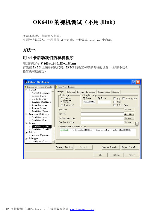
OK6410的裸机调试(不用Jlink)废话不多说,直接进入主题。
有两种方法写入,一种是从sd卡启动,一种是从nand flash中启动。
方法一:用sd卡启动我们的裸机程序用到的软件:WinHex_14.0_SR-1_SC.exe首先在RVDS上编译裸机代码,RVDS的设置可以参考我的设置,(好像不这么设置也可以成功)我的这项设置输出的是文件名为zImage的二进制代码文件。
注意是zImage!!没有.bin!之后一种方法就用到它,暂且先说了吧。
插入已经格式化的SD卡,打开WinHex_14.0_SR-1_SC.exe这个软件。
S3C6410 SD 启动模式原理: 上电后,CPU自动将SD0丛最后0x23FF 处,连续8KB数据读到内部SRAM 0x0C000000处执行.就这样,我们的裸奔程序就写到SD卡中了,把OK6410设置为SD卡启动,就可以看到我们的裸机程序在运行了!方法二:借助uboot把我们的裸机程序从nand flash中启动起来!我们一键烧写的方法,将SD做一些准备。
打开SD_Writer.exe然后把uboot.bin拷贝到H盘中(SD卡的盘符)可以用位于OK6410-A 6410官方基础资料-2G\linux2.6.28\demo下的uboot.bin 接下来把我们刚刚生成的裸机目标文件“zImage”拷贝到SD卡中。
设置OK6410为SD卡启动,用dnw观察打印的信息,看到此信息就说明烧写完成了。
完成后把板子设置为nandflash启动,就可以“裸奔”了看到这个信息就说明你的裸机程序在执行了总结方法一借鉴了别人的想法,方法二是本人自己摸索出来的!大家一起学习,一同进步!DIY爱好者2011年6月20日。
ok6410开发板交叉编译器的安装

ok6410开发板交叉编译器的安装
1.上篇文章中我们说了已经在虚拟机里面的ubuntu12 根目录下建立了
forlinx 文件夹,现将arm-linux-gcc.4.3.2.tgz 拷贝到forlinx 中,我用的是上次建立
好的xftp,相当爽啊2. cd ../../
ls
cd forlinx
mkdir /usr/local/arm
tar zxvf arm-linux-gcc-4.3.2.tgz -C /,注意这里的斜杠不要丢掉
这样解压到了/usr/local/arm
然后运行这个命令gedit /etc/profile
再把以下四行加入文件的头部(尾部我试了反正我的不管用,不知道为啥)
export PATH=/usr/local/arm/4.3.2/bin:$PATH export TOOLCHAIN=/usr/local/arm/4.3.2 export TB_CC_PREFIX=arm-linux- export PKG_CONFIG_PREFIX=$TOOLCHAIN/arm-none-linux-gnueabi
然后reboot,reboot 后terminal 中输入arm-linux-gcc -v 就可以看到信息了很好
tips:感谢大家的阅读,本文由我司收集整编。
仅供参阅!。
LDD6410-manual
目 录1. LDD6410 硬软件特性 .................................................................................................................................................. 3 1.1 LDD6410 的电路板组成和结构 ........................................................................................................................ 3 2.1 建立工具链和开发环境 . (8)2.1.1 S3C6410X ToolChain4.2.2 EABI ............................................................................................................... 8 2.1.2 strace 、 gdbserver 和 arm linux gdb .......................................................................................................... 9 2.1.3 gdb 调试器的用法 ................................................................................................................................... 9 2.1.4 主机端 tftp 和 nfs 服务安装 ................................................................................................................... 11 2.2 U BOOT . (11)2.2.1 UBOOT 的移植 .................................................................................................................................... 11 2.2.2 NAND 版 U BOOT ................................................................................................................................ 12 2.2.3 SD 卡 版 U BOOT ................................................................................................................................ 13 2.2.4 从 tftp 服务器引导 Linux ...................................................................................................................... 13 2.3 Linux 内核和驱 动 . (14)2.3.1 LDD6410 内核和 BSP ............................................................................................................................ 14 2.3.3 LED 驱动 ............................................................................................................................................... 17 2.3.4 LCD 和 VGA 驱动 ................................................................................................................................. 18 2.3.7 USB 驱动 ............................................................................................................................................... 24 2.3.8 驱动学习实例: helloworld 、 globalmem 、 globalfifo ........................................................................ 26 2.4 根文件系统 . (27)2.4.1 根文件系统的组成 ................................................................................................................................ 27 2.4.2 使用 nfs 作为根文件系统 ..................................................................................................................... 32 2.5 应用程序 .. (32)2.5.2 USB 鼠标测试程序 ............................................................................................................................... 36 2.5.3 触摸屏测试程序 .................................................................................................................................... 38 2.5.4 framebuffer 测 试 程 序 ...................................................................................................................... 41 2.5.4 jpegview 图片浏览器 ............................................................................................................................ 42 2.5.5 mplayer 媒体播放器 .............................................................................................................................. 43 2.5.6 appweb 服 务 器 .................................................................................................................................. 44 2.6 Android . (44)2.6.2 Android 文件系统 ................................................................................................................................. 46 2.7.1 Tslib 和 ts_calibration ............................................................................................................................. 48 2.7.2 Qt (50)3. LDD6410 Linux 软件包的烧录与更新 (52)3.1 SD 卡烧录 (52)3.2.153........................................................................................................................版 U BOOT更新NAND内核53.......................................................................................................Linux分区中的更新3.2.2NAND..........................................................................................................54更新3.2.3NAND分区中的文件系统LDD6410 开发板用户手册1. LDD6410硬软件特性1.1 LDD6410的电路板组成和结构LDD6410 是一款高端 ARM11 处理器开发板,采用三星公司最新推出 S3C6410 处理器,芯片拥有强大的内部资源和视频处理能力,板上集成了丰富的外围接口,其主要特点如下:1. 运行于 533MHz 的 ARM11 处理器(最高主频可达到 667MHz)2. 运行于 266MHz 的 DDR 内存,128MB3. 1MB NOR FLASH4. 256MB NAND FLASH5. WM9714 AC97 声卡6. VGA 输出接口(可达 1024*768@60Hz)7. TV 输出接口8. USB 2.0 OTG 接口及 USB 1.1 host 接口9. SD/SDIO 接口,支持 SD 卡和 SDIO 设备9. DM9000 百兆网卡10. LCD、触摸屏11. S3C6410 芯片内嵌图形加速,JPEG、多媒体编解码12. 6 个 GPIO 按键13. 可扩展 Camera、WiFi、3G modem 等模块14. 可扩张外部矩阵键盘LDD6410 电路板的结构如下图:其实物图如下:LDD6410 的 LCD 输出显示效果如下图:LDD6410 的 VGA输出显示效果如下图:1.2 LDD6410的启动跳线设置通过电路板上的 SW1 可设置 LDD6410 的启动模式,从 SD 卡启动设备为全 ON,从NAND 启动时,将 1、2 设置为 ON,3、4 设置为 OFF。
ARM11 DMA-6410 开发平台

ARM11 DMA-6410 開發平台■簡介與特色DMA-6410採用Samsung S3C6410 處理器,獨有的3D 及支援DVFS 的同時並擁有低功耗的記憶體介面特性對於設計者來說是一款非常划算的處理器。
這款32 位元,ARM11 核的微處理器採用AXI、AHB 和APB 匯流排組成的64/32-bit 內部匯流排結構界面,處理能力最大可達667MHz。
由於擁有3D 圖形硬體加速器(處理速度可達4百萬個多角形每秒),其強大的硬體加速器可以輕鬆完成視頻處理、音訊處理、3D 圖像加速及顯示操作與縮放等動作。
其內部並整合了多格式解碼器(MFC),支援Mpeg4/H.263/H.264 的編碼與解碼,並支援VC1 解碼。
這種H/W 編碼/解碼器支援即時視訊會議系統,以及NTSC 和所有PAL 制式的電視信號輸出。
該處理器可以用於下一代手持設備,比如,移動網路設備,3D 增強型多媒體手機,能夠顯示更加詳細的圖像(比如建築,地界標誌)的個人導航設備。
S3C6410 的記憶體技術非常先進,為了能夠處理高端通信服務對記憶體大小的要求,它給處理器提供了很多選擇的方法。
記憶體支援包括雙向DRAM、Flash/ROM。
DRAM端可支援Mobile DDR,標準SDRAM 或集成的OneDRAM,而Flash/ROM 端可支援NANDFlash、NOR flash、OneNAND 及ROM。
■ 平台硬體配置∙中央處理器CPU:Samsung S3C6410XHL-66,主頻為667MHz,內核為ARM1176JZF-S ∙外部記憶體*SDRAM 記憶體:平台上提供64M*3 片Mobile DDR SDRAM ,其中2 片共128M 的標準配置用於系統運作, 1 片64MB 用於視訊、圖像處理* NOR Flash:2MByte 記憶體* NAND FlashSLC NAND Flash:兼容64 / 128MByte 記憶體MLC NAND Flash:1G / 2G / 4G Byte記憶體(Option)∙網路介面二個10/100M Ethernet,採用DM9000AE,帶指示燈RJ-45 介面∙USB 介面一個USB HOST(USB 1.1 規範)介面,支援全速(12Mbps)或低速(1.5Mbps)傳輸一個USB HS OTG(USB2.0規範)介面,最高支援480Mbps高速傳輸∙串列埠一個 5 線制串列埠,三個複用串列埠( 與BlueTooth / GPS / IIC 複用)∙音效介面採用AC97 的介面晶片,立體聲音效輸出介面可接耳機或音箱;支援錄音,底板有音效輸入介面可接麥克風∙紅外通訊介面採用高靈敏度RPM851A 紅外收發模組,標準配置,和串列埠3複用∙CMOS Sensor攝影機介面底板上內置一個130 萬像素的CMOS Sensor 攝影機,可直接攝影並在液晶螢幕上顯示,並有一個 2.0mm 間距雙排插座用於攝影機擴充,這個擴充介面可連接其他型號的CMOS Sensor 攝影機,支援的標準為ITU-R BT.601/656 YCBCR 8-bit standard∙LCD 介面*相容 3.3V / 5V 供電LCD 螢幕*系統平台標配為16.7M色800x480 / 7.0 英寸TFT 液晶螢幕,附觸控功能*支援TFT 液晶螢幕,尺吋從 3.5 吋到15 吋,板上可供TFT LCD 逆變器電源(+5V)∙Touch 介面一個觸控螢幕控制器(四線電阻式)∙VGA 介面可直接連接各種VGA 介面的CRT 顯示器或液晶顯示器,帶對比度微調電位器,最高輸出解析度為1024*768∙TV(NTSC / PAL)介面支援TV Tunet(NTSC及PAL),可直接接各種AV 介面的CRT 顯示器∙S-VIDEO 介面一個,S-VIDEO 視訊信號輸出∙SD 卡介面一個高速SD / HSMMC 和SDIO 設備Linux:*Linux 2.6.24:支援高速SDHC 卡(SD 2.0)2G / 4G / 8G / 16G / 32GByte並兼容標準SD 1.1WinCE:* WinCE 6.0:支援高速SDHC 卡(SD 2.0)2G / 4G / 8G / 16G / 32GByte 並兼容標準SD 1.1∙Micro SD(T-Flash)卡介面一個T-Flash 存儲設備∙多功能擴充介面16Bit 資料匯流排/ 32Bit 位址匯流排/ 片選、讀寫、中斷等系統控制匯流排∙RTC 時鐘S3C6410 內部集成,外部提供RTC電池,插座安裝,可更換∙JTAG 介面一個10 Pin JTAG 介面位於核心板上,一個ARM 標準20PIN JTAG 介面位於底板上,可支援核心板單獨除錯,也可通過底板支援ADS2.2以上版本等除錯∙CAN 匯流排介面一個CAN 匯流排介面,全面支援CAN2.0A 和CAN2.0B 協議∙內嵌GPS 模組介面(Option)採用高靈敏度、低耗電量、高性能低價位MTK GPS 晶片。
飞凌OK6410安卓2.3.4的编译环境搭建与烧写

飞凌OK6410安卓2.3.4的编译环境搭建与烧写飞凌 OK6410 安卓 2.3.4 的编译环境搭建与烧写1、⼯具下载及其环境搭建 本⽂环境:VMWare 15 PRO,Ubuntu16.04.6_amd64(64位的版本),安卓 2.3.4 下⾯进⼊主题,先搭建编译环境吧,虚拟机不知道怎么创建的,请看上⾯给出的链接,这⾥⾯我介绍了⼗分全⾯,包括git,make,gcc,g++等等的配置 飞凌 OK6410 安卓代码下载地址::提取码:w2ue 由于飞凌提供的代码是按照 32 位环境编译的,⾥⾯提供的⼯具也⾃然都是 32 位的了(包括⾥⾯提供的 jdk ),所以⾃⼰去下对应版本的 jdk 吧。
当然我这⾥也会提供。
飞凌提供的32位版本jdk 版本对应⼀致的 jdk 的下载地址::提取码:wdei 由于Ubuntu16.04 ⾃带的 make版本过⾼,需要降低 make 版本 make 3.8.1 源码的下载地址::提取码:2spp2、安装教程 make 降低版本安装教程地址:2.1、gcc,g++ 降低版本 之所以要降低版本,因为 Ubuntu16.04 ⾃带的各种⼯具版本版本都太⾼了,编译低版本安卓时会报很多错误,因此需要将⼀些⼯具降低版本使⽤ gcc,g++ 降低版本教程地址:! 安装依赖环境:1sudo apt-get install bison2sudo apt-get install zlib1g-dev3sudo apt-get install lib32z1-dev4sudo apt-get install flex5sudo apt-get install libncurses5-dev6sudo apt-get install libncurses5-dev:i3867sudo apt-get install libx11-dev8sudo apt-get install gperf9sudo apt-get install libswitch-perl10sudo apt-get install libsdl1.2debian:i3862.2、jdk 64位安装 因为我这⾥使⽤的是 64 位的 Ubuntu16.04 下载地址在上⾯已经提供,编译相关的⼯具链我个⼈习惯放置 /opt ⽬录下1mv jdk-6u23-linux-x64.bin /opt 更改属性1chmod u+x jdk-6u23-linux-x64.bin 运⾏⾃动解压1 ./jdk-6u23-linux-x64.bin 配置 jdk 使其对所有⽤户⽣效,注意:如果配置这⼀步,则需要修改飞凌安卓代码⾥头的编译脚本1sudo vim /etc/profile23 export JAVA_HOME=/opt/jdk1.6.0_234 export JRE_HOME=${JAVA_HOME}/jre5 export CLASSPATH=.:$JAVA_HOME/lib:$JAVA_HOME/jre/lib6 export PATH=$JAVA_HOME/bin:$JAVA_HOME/jre/bin:$PATH:$HOME/bin 针对飞凌,不⽤在 /etc/profile 中配置,直接将 ./jdk-6u23-linux-x64.bin 解压出来的⽂件放置安卓源码中 android2.3.4-32bit/ ⽬录下,替换飞凌提供的 32位 jdk 如果要在 /etc/profile 中对 jdk 进⾏全局⽣效,那就将 build-android 脚本中的第6⾏ export PATH=$PATH:$PWD/jdk1.6.0_23/bin 注释掉3、编译 解压安卓代码1tar -zxvf android2.3.4_32bit-2012-10-11.tar.gz 提供的源码适⽤于 32 位系统下编译,⾸先确定你的linux 是否是 32 位或 64 位的系统,⽤命令 uname -a 可以查看,如果是 64 位操作系统请坐以下修改 如果你使⽤的是 32 位系统,请忽略这⼀步1 ./external/clearsilver/cgi/Android.mk23 ./external/clearsilver/java-jni/Android.mk45 ./external/clearsilver/util/Android.mk67 ./external/clearsilver/cs/Android.mk 四个⽂件中的1 LOCAL_CFLAGS += -m6423 LOCAL_LDFLAGS += -m6445//注释掉,或者将“64”换成“32”67 LOCAL_CFLAGS += -m3289 LOCAL_LDFLAGS += -m32 然后,将 ./build/core/main.mk 中的 ifneq (64,$(findstring 64,$(build_arch))) 改为: ifneq (i686,$(findstring i686,$(build_arch)))在 dalvik/vm/native/dalvik_system_Zygote.cpp ⽂件中添加头⽂件#include <sys/resource.h> 开始编译:1 /forlinx/android2.3.4_32bit# ./build-android2 including device/htc/passion/vendorsetup.sh3 including device/samsung/crespo/vendorsetup.sh4 ============================================5 PLATFORM_VERSION_CODENAME=REL6 PLATFORM_VERSION=2.3.47 TARGET_PRODUCT=OK64108 TARGET_BUILD_VARIANT=eng9 TARGET_SIMULATOR=false10 TARGET_BUILD_TYPE=release11 TARGET_BUILD_APPS=12 TARGET_ARCH=arm13 HOST_ARCH=x8614 HOST_OS=linux15 HOST_BUILD_TYPE=release16 BUILD_ID=GRJ06D17 ============================================18 Checking build tools versions...1920 ... ...2122 Generated: (out/target/product/OK6410/android-info.txt)23 Target system fs image: out/target/product/OK6410/obj/PACKAGING/systemimage_intermediates/system.img24 Install system fs image: out/target/product/OK6410/system.img25 Target ram disk: out/target/product/OK6410/ramdisk.img26 Target userdata fs image: out/target/product/OK6410/userdata.img27 Installed file list: out/target/product/OK6410/installed-files.txt制作⽂件系统 制作⽂件系统 : 根⽬录下提供了制作⽂件系统的脚本, make-rootfs-nand2g, 执⾏这个脚本即可制作根⽂件系统; -- 命令 : 进⼊ Android 源码根⽬录, 执⾏ ./make-rootfs-nand2g 命令, 之后在根⽬录⽣成 rootfs.yaffs2 就是制作的根⽂件系统; -- 注意 : ⼀定要区分这两个脚本, make-rootfs-nand256m ⽤于制作 128M 内存 256 M NandFlash 的开发板的⽂件系统, make-rootfs-nand2g ⽤于制作 256M 内存 2G NandFlash 开发板的⽂件系统;1 /forlinx/android2.3.4_32bit# ls2 bionic cts external libcore make-rootfs-nand2g ndk Readme vendor3 bootable dalvik frameworks Makefile make-rootfs-nand2g~ out sdk4 build development hardware make-rootfs-nand256m mkyaffs2image-nand256m packages setenv5 build-android device jdk1.6.0_23 make-rootfs-nand256m~ mkyaffs2image-nand2g prebuilt system6 root@octopus:/forlinx/android2.3.4_32bit# ./make-rootfs-nand256m7 Generating rootfs for Android......done8 Create device file......done9 Install prebuilt packages......done10 Install firmware for 3G ......done11 Install ppp for 3G...done12 Install usb_modeswitch.d for 3G...done13 Install Dialup for 3G...done14 Install ForlinxLED permissions fileInstall Apps filemkyaffs2image: image building tool for YAFFS2 built Nov 24201115 Processing directory rootfs_dir into image file rootfs.yaffs21617 ... ...1819 bject 1457, rootfs_dir/system/bin/sdcard is a file, 5 data chunks written20 Object 1458, rootfs_dir/system/bin/dumpstate is a file, 17 data chunks written21 Object 1459, rootfs_dir/system/bin/bootanimation is a file, 12 data chunks written22 Object 1460, rootfs_dir/system/bin/Looper_test is a file, 35 data chunks written23 Object 1461, rootfs_dir/system/bin/ioctl is a symlink to "toolbox"24 Object 1462, rootfs_dir/system/bin/dvz is a file, 3 data chunks written25 Object 1463, rootfs_dir/forlinx.rc is a file, 1 data chunks written26 Operation complete.272414 objects in63 directories2835361 NAND pages29 ...done30 ...done31 /forlinx/android2.3.4_32bit# ls32 bionic cts external libcore make-rootfs-nand2g ndk Readme setenv33 bootable dalvik frameworks Makefile make-rootfs-nand2g~ out rootfs_dir system34 build development hardware make-rootfs-nand256m mkyaffs2image-nand256m packages rootfs.yaffs2 vendor35 build-android device jdk1.6.0_23 make-rootfs-nand256m~ mkyaffs2image-nand2g prebuilt sdk4、配置 U-boot、kernel 的编译环境 将飞凌6410-android2.3-20140613\编译器⽬录下的 arm-linux-gcc-4.3.2.tgz、arm-none-linux-gnueabi-arm-2008q3-72-for-linux.tar.bz2 两个编译链拷贝到虚拟机中并解压 我个⼈习惯放置 /opt ⽬录下,1sudo mv arm-linux-gcc-4.3.2.tgz /opt2sudo mv arm-none-linux-gnueabi-arm-2008q3-72-for-linux.tar.bz2 /opt 解压:1 sudo tar -zxvf arm-linux-gcc-4.3.2.tgz -C /opt2 sudo tar -jxvf arm-none-linux-gnueabi-arm-2008q3-72-for-linux.tar.bz2 -C /opt 全局变量⽣效:1 vim /etc/profile23 export PATH=$PATH:/opt/usr/local/arm/arm-none-linux-gnueabi/bin4 export PATH=$PATH:/opt/usr/local/arm/4.3.2/bin 机器重启或者 . /etc/profile 或者 source /etc/profile ⽴即⽣效编译 U-boot 将飞凌提供的 U-boot 代码 uboot1.1.6-2012-10-11.tar.gz,Kernel 代码 android2.3_kernel_v3.00-2014-06-12.tar.gz 复制到你的⼯作空间去 解压 U-boot 代码1tar -zxvf uboot1.1.6-2012-10-11.tar.gz 进⼊ U-boot 顶层⽬录,修改 Makefile 找到 CROSS_COMPILE ,将其对应的交叉编译⼯具链路径指定上⾯那个 CROSS_COMPILE = /opt/usr/local/arm/4.3.2/bin/arm-linux- 编译配置适⽤于 128M 内存开发板的 config make forlinx_nand_ram128_config make clean make 编译配置适⽤于 256M 内存开发板的 config make forlinx_nand_ram256_config make clean make 编译成功后,将在 uboot1.1.6 ⽬录下⽣成名为 u-boot.bin 的⼆进制⽂件。
SMDK6400_6410_Linux_2.6.21_APM_Porting_Guide_REV1.00_20070710

Porting Guidefor APMSMDK6400July 10, 2007(Preliminary) REV 1.00 Confidential Proprietary of Samsung Electronics Co., LtdCopyright © 2007 Samsung Electronics, Inc. All Rights ReservedPreliminary product information describe products that are in development, Important NoticeThe information in this publication has been carefully checked and is believed to be entirelyaccurate at the time of publication. Samsung assumes no responsibility, however, for possible errors oromissions, or for any consequences resulting from the use of the information contained herein.Samsung reserves the right to make changes in its products or product specifications with the intent to improve function or design at any time and without notice and is not required to update this documentation to reflect such changes.This publication does not convey to a purchaser of semiconductor devices described herein any license under the patent rights of Samsung or others. Samsung makes no warranty, representation, or guarantee regarding the suitability of its products for any particular purpose, nor does Samsung assume any liability arising out of the application or use of any product or circuit and specifically disclaims any and all liability, including without limitation any consequential or incidental damages. "Typical" parameters can and do vary in different applications. All operating parameters, including "Typicals" must be validated for each customer application by the customer's technical experts. Samsung products are not designed, intended, or authorized for use as components in systems intended for surgical implant into the body, for otherapplications intended to support or sustain life, or for any other application in which the failure of the Samsung product could create a situation where personal injury or death may occur.Should the Buyer purchase or use a Samsung product for any such unintended or unauthorized application, the Buyer shall indemnify and hold Samsung and its officers, employees, subsidiaries, affiliates, and distributors harmless against all claims, costs, damages, expenses, and reasonable attorney fees arising out of, either directly or indirectly, any claim of personal injury or death that may beassociated with such unintended or unauthorized use, even if such claim alleges that Samsung wasnegligent regarding the design or manufacture of said product.Porting Guide for APM, Preliminary Revision 1.00Copyright © 2007-2007 Samsung Electronics Co.,Ltd.All rights reserved. No part of this publication may be reproduced, stored in a retrieval system, or transmitted in any form or by any means, electric or mechanical, by photocopying, recording, or otherwise, without the prior written consent of Samsung Electronics Co.,Ltd. Samsung Electronics Co., Ltd.San #24 Nongseo-Dong, Giheung-Gu Yongin-City Gyeonggi-Do, Korea 446-711Home Page: / E-Mail: mobilesol.cs@Printed in the Republic of KoreaPreliminary product information describe products that are in development, Revision HistoryRevision No Description of ChangeRefer toAuthor(s) Date 1.00- Initial Release for review-JC.LEEJune 26, 2007NOTE: Revised parts are written in blue.Preliminary product information describe products that are in development, Table of Contents1INTRODUCTION ............................................................................................................... 7 1.1 O VERVIEW .................................................................................................................. 7 1.2 FEATURES ................................................................................................................ 7 1.2.1 H/W feature ........................................................................................................ 7 1.2.2 S/W feature ........................................................................................................ 7 2SETUP APM TEST ENVIRONMENT & CONDITION ........................................................................ 8 2.1 E NVIRONMENT O VERVIEW ................................................................................................... 8 2.2 C ONDITION O VERVIEW ...................................................................................................... 8 3SUPPORTING APM MODE .................................................................................................... 9 3.1 PM _OPS STRUCTURE ......................................................................................................... 9 3.1.1 valid ................................................................................................................. 9 3.1.2 prepare ............................................................................................................. 9 3.1.3 enter ................................................................................................................ 9 3.1.4 finish ................................................................................................................ 9 3.1.5 pm_disk_mode ..................................................................................................... 9 4CODING GUIDE FOR SPECIAL H/W DEPENDENCY. .................................................................... 11 4.1 S3C6400 SPECIFIC CODE ................................................................................................. 11 4.1.1 s3c6400_pm_enter .............................................................................................. 11 4.1.2 s3c6400_cpu_suspend ........................................................................................... 11 4.2 T EST A PPLICATION .. (12)Preliminary product information describe products that are in development, Table그림 목차 항목을 찾을 수 없습니다.Preliminary product information describe products that are in development, Figures그림 목차 항목을 찾을 수 없습니다.Preliminary product information describe products that are in development, 1 IntroductionIn this Chapter, you will understand the following:z Section 1.1, “Overview” z Section 1.2, “Features”1.1 OverviewS3C6400X supports low power application through low power mode operation as illustrated in Table 1-1.There are four power states, which are normal state, retention state, power gating state, and power off state. All internal logics including F/Fs and memory are running at normal state. Retention state reduces unwanted power consumption during STOP/DEEP-STOP mode, however, retains previous states and supports fast wake-up time from STOP/DEEP-STOP mode. Some blocks, which are DOMAIN-V, DOMAIN-I, DOMAIN-P, DOMAIN-F, and DOMAIN-S, have no state retention feature. They can be power gating to reduce power consumption through an internal power switch circuitry. The response time of the internal circuitry, about several usec, is faster than that of an external power regulator. In SLEEP mode, an external regulator will be OFF to reduce powerconsumption and S3C6400X minimizes power consumption and lose all information except ALIVE and RTC block.1.2 FEATURES1.2.1 H/W featurezPower Domainz NORMAL/IDLE mode z STOP modez DEEP-STOP mode z SLEEP modez Wakeup from low power state zResetH/W reset Warm reset Watchdog reset Software reset Wakeup reset1.2.2 S/W featurez Support “suspend to mem”z “Sysfs” file system z RTC alarm wakeupPreliminary product information describe products that are in development, 2 Setup APM test Environment & ConditionIn this Chapter, you will understand the following:z Setup for APM test environment z Setup root file system to test APM2.1 Environment OverviewCategoryContentsRemarkT ool chain Arm cross compilerFor application compiling Gcc 4.0.3 arm cross compiler For kernel compiling Kernel Embedded linux 2.6.21 For smdk6400T est tool rtc_pm.c Based on RTC test application Root file systemCramfs or MTD, Sysfs file systemAdd device node for RTC. Mount sysfs file system Device nodes /dev/rtc0Major : 254, minor : 02.2 Condition OverviewCategoryT est ApplicationRemarkSleep/Wakeup Aging testrtcpm24Hr Aging test. RTC alarm wakeup.Preliminary product information describe products that are in development,3 Supporting APM ModeIn this Chapter, you will understand the following:z pm_ops structure3.1 pm_ops structureCallbacks for managing platform dependent suspend states. struct pm_ops { int (*valid)(suspend_state_t state); int (*prepare)(suspend_state_t state); int (*enter)(suspend_state_t state); int (*finish)(suspend_state_t state); suspend_disk_method_t pm_disk_mode; };3.1.1 validCallback to determine whether the given state can be entered. If %CONFIG_SOFTWARE_SUSPEND is set then %PM_SUSPEND_DISK is always valid and never passed to this call.If not assigned, all suspend states are advertised as valid in /sys/power/state (but can still be rejected by prepare or enter.) Implementation Remark Not assigned N/A3.1.2 preparePrepare the platform for the given suspend state. Can return a negative error code if necessary. Implementation Remark static int s3c2410_pm_prepare(suspend_state_t state) T o Do.3.1.3 enterEnter the given suspend state, must be assigned. Can return a negative error code if necessary. Implementation Remark static int s3c6400_pm_enter(suspend_state_t state) Enter sleep mode.3.1.4 finishCalled when the system has left the given state and all devices are resumed. The return value is ignored. Implementation Remark static int s3c2410_pm_finish(suspend_state_t state) T o Do.3.1.5 pm_disk_modeSet to the disk method that the user should be able to configure for suspend-to-disk.Since %PM_DISK_SHUTDOWN, %PM_DISK_REBOOT, %PM_DISK_TEST and %PM_DISK_TESTPROC are always allowed, currently only %PM_DISK_PLATFORM makes sense. If the user then choses %PM_DISK_PLATFORM, the @prepare call will be called before suspending to disk (if present), the @enter call should be present and will be called after all state has been saved and the machine is ready to be shut down/suspended/..., and the @finishcallback is called after state has been restored. All these calls are called with %PM_SUSPEND_DISK as the state. Implementation RemarkPreliminary product information describe products that are in development, PM_DISK_FIRMWARE N/A.Preliminary product information describe products that are in development,4 Coding Guide for Special H/W dependency.In this Chapter, you will understand the following:z Specific code for supporting S3C6400.z Examining test application with RTC device driver.4.1 S3C6400 specific code4.1.1 s3c6400_pm_enter4.1.2 s3c6400_cpu_suspendThis function will assert sleep signal to S3C6400.Preliminary product information describe products that are in development,4.2 Test ApplicationPreliminary product information describe products that are in development,Preliminary product information describe products that are in development,curr_cnt ++;/* Disable alarm interrupts */ retval = ioctl(fd, RTC_AIE_OFF, 0);if (retval == -1) { perror("RTC_AIE_OFF ioctl");exit(errno); }retval = ioctl(fd, RTC_RD_TIME, &rtc_tm);if (retval == -1) { perror("RTC_RD_TIME ioctl");exit(errno); }fprintf(stderr, "\n\nCurrent RTC date/time is %d-%d-%d, %02d:%02d:%02d.\n", rtc_tm.tm_mday, rtc_tm.tm_mon + 1, rtc_tm.tm_year + 1900, rtc_tm.tm_hour, rtc_tm.tm_min, rtc_tm.tm_sec);/* Set the alarm to specific sec in the future, and check for rollover */rtc_tm.tm_sec += interval; if (rtc_tm.tm_sec >= 60) {rtc_tm.tm_sec %= 60; rtc_tm.tm_min++;} if (rtc_tm.tm_min == 60) {rtc_tm.tm_min = 0; rtc_tm.tm_hour++;} if (rtc_tm.tm_hour == 24)rtc_tm.tm_hour = 0;retval = ioctl(fd, RTC_ALM_SET, &rtc_tm);if (retval == -1) { if (errno == ENOTTY) {fprintf(stderr, "\n...Alarm IRQs not supported.\n");goto error; }perror("RTC_ALM_SET ioctl"); exit(errno);}/* Read the current alarm settings */ retval = ioctl(fd, RTC_ALM_READ, &rtc_tm);if (retval == -1) { perror("RTC_ALM_READ ioctl");exit(errno); }fprintf(stderr, "Alarm time now set to %02d:%02d:%02d.\n",rtc_tm.tm_hour, rtc_tm.tm_min, rtc_tm.tm_sec);/* Enable alarm interrupts */ retval = ioctl(fd, RTC_AIE_ON, 0);if (retval == -1) {perror("RTC_AIE_ON ioctl");Preliminary product information describe products that are in development,exit(errno);}fprintf(stderr, "System will be waken after %d seconds by RTC ALARM\n",interval); fprintf(stderr, "System enters sleep mode. Zzz...\n");retval = write(fd_pm, pm_mode, sizeof(pm_mode));if(retval == -1) {fprintf(stderr, "Sleep failed\n"); exit(errno);} fflush(stderr);/* Sleep task during 3 seconds*/ fprintf(stderr, "Sleep Counter = %d\n", curr_cnt);sleep(3); }error: close(fd);close(fd_pm); return 0;}。
控制面板 CP600 2代 CP6407、CP6410、CP6415 操作指南说明书
—OPERATING INSTR UCTIONControl panels CP600 2nd generation CP6407, CP6410, CP6415Contents1Introduction (3)2Safety guide (4)2.1Safety guide (4)2.2Safety notices (4)2.3Markups (5)3Product overview (6)4Standards and approvals (7)4.1Product identification (7)5Technical specifications (9)6Technical data (11)6.1Dimensions (12)6.2Installation environment (13)6.3Safety instruction (14)6.4Installation procedure (14)7Connections (15)7.1CP600 2nd generation (15)7.2Serial port (16)7.3Ethernet port (16)8Power supply, grounding and shielding (17)9Battery (19)9.1Dispose of batteries (19)10Special instruction for use (20)11Cleaning faceplates (20)12Getting started (20)13System settings (21)14Unpacking and packing instructions (23)2 3ADR010470, 3, en_USCONTROL PANELS CP600 2ND GENERAT IONCP600 2nd generation, 3, en_US 31 IntroductionThe operational guidelines described below are information on device technical data, installation, transportation, storage, assembly, use and maintenance. The Manual refers to the following models: PictureType DescriptionCP6407Operator interface with 7” color widescreen display and resistive touchscreenCP6410Operator interface with 10”4 color display and resistive touchscreeCP6415Operator interface with 15” color display and resistive touchscreen2Safety guide2.1Safety guideThe manual contains safety standards that must be respected for the personal safetyand to avoid damage.Indications of attention are divided into three levels of severity.2.2Safety notices4 3ADR010470, 3, en_USCONTROL PANELS CP600 2ND GENERAT ION2.3MarkupsEnumeration.Precondition for an operation instruction or a description.Operation instruction with one step.1. Operation instruction with several steps.Result of an operation.CP600 2nd generation, 3, en_US 53Product overviewCP600 2nd generation HMI products combine state-of-the-art features and great perfor-mance in a compact and robust design.They have been designed to offer competitive price/performance ratio for challenging indus-trial applications where robust devices are a requirement.These products feature a full die-cast aluminum housing. Compatibility with CP600 seriescut-out offers an easy upgrade path for the old series.CP600 2nd generation products have been designed to run PB610 software with outstandingcommunication and graphical options.•Efficient and secure Linux operating system•Gateway function with Server and Client OPC UA•aFull PB610 vector graphic support•Efficient unified programming strategy for web HMI applications6 3ADR010470, 3, en_USCONTROL PANELS CP600 2ND GENERAT ION4Standards and approvalsThe products have been designed for use in an industrial environment in compliance with the2014/30/EU EMC Directive.The products have been designed in compliance with:EN 61000-6-4EN 61000-6-2 EN 61000-4-2EN 61000-4-3EN 61000-4-4EN 61000-4-5EN 61000-4-6EN 61000-4-8EN 61000-4-29EN60945The installation of these devices into the residential, commercial and light-industrial environ-ments is allowed only in the case that special in measures are taken in order to ensure con-formity to EN 61000-6-3.The products are in compliance with the Restrictions on Certain Hazardous Substances(RoHS) Directive 2011/65/EUIn compliance with the above regulations the products are CE marked.4.1Product identificationThe product may be identified through a plate attached to the rear cover. You will have toknow the type of unit you are using for correct usage of the information contained in theguide.An example of this plate is shown in the figure below:Note: the CP6407 label is used as an example for CP600 2nd generation Series.CP600 2nd generation, 3, en_US 783ADR010470, 3, en_USInformation on type plate (example) Description Product model name CP6407Product part number 1SAP540710R0001Serial number S.N.: AAxxxxxxxxxxxxxxxxAA Product version ID V.: xxxxxxxxxxxxxxx Manufacturer addressABB AGEppelheimer Straße 82, 69123 HeidelbergGermanyCONTROL PANELS CP600 2ND GENERAT IONCP600 2nd generation, 3, en_US 95 Technical specificationsTouchscreen technology ResistiveBack-up battery3 V 50 mAh Lithium, rechargeable, not user-replaceable, model VL2330.Fuse AutomaticSerial port RS-232, RS-485, RS-422 software configurable Flash 4 GB RAM512 MBHardware clock Clock/Calendar with back-up battery Accuracy RTC (at 25°C) < 100 ppmEnvironmental conditions Operating temperature -20 … +60 °C (vertical installation) EN 60068-2-14 Storage temperature-20 … +70 °CEN 60068-2-1 EN 60068-2-2 EN 60068-2-14 Operating and storage humidity 5 … 85 % RH not-condensing EN 60068-2-30Vibrations 5 … 9 Hz, 7 mm; 9 … 150 Hz, 1 g p-p EN 60068-2-6 Shock± 50 g, 11 ms, 3 pulses per axis EN 60068-2-27 Protection classFront panel IP66, Rear IP20EN 60529Electromagnetic Compatibility (EMC) Electrostatic discharge immunity test8 kV (air electrostatic discharge)4 kV (contact electrostatic discharge)EN 61000-4-2Radiated, radio-frequency, electromagnetic field immunity test 80 MHz … 1 GHz, 10 V/m 1.4 GHz … 2 GHz, 3 V/m 2 GHz … 2.7 GHz, 1 V/m EN 61000-4-3Burst immunity test±2 kV DC power port±1 kV signal lineEN 61000-4-4Surge immunity test ±0,5 kV DC power port (line to earth) ± 1 KV dc power port (line to line) ±1 kV signal line (line to earth) EN 61000-4-5Immunity to conducted disturbances inducted by radiofrequency field0.15…80 MHz, 10 VEN 61000-4-6Power frequency magnetic field immunity testEnclosure, 50 Hz, 30 A/m EN 61000-4-8Voltage dips, short interruptions and voltage variations immunity test Port: DC mains; Level:0% duration: 10 ms 20 spaces by 1 sTest executed on the 24 VDC of the EUTEN 61000-4-29Durability informationBacklight service life (LED type) 40000 hr. or more(Time of continues operation until the brightness of the backlight reaches 50 % of the rated value when the ambient temperature is 25 °C) - see Note 1Note 1: Extended use in environments where the ambient temperature is 40 °C or higher may degrade backlight quality/reliability/durability.10 3ADR010470, 3, en_US6Technical dataModel CP6407 CP6410 CP6415Display TFT Color / LED TFT Color / LED TFT Color / LEDColors 64K 64K 64KResolution 800X480 800X600 1024X768Diagonal 7” widescreen 10.4” 15”Dimming yes yes yesFlash 4GB 4GB 4GBSD card slot yes yes yesRAM 512MB 512MB 512MBSerial port RS-232,RS-485, RS-422software configurable RS-232,RS-485, RS-422software configurableRS-232,RS-485, RS-422software configurableEthernet port 2 10/100Mb 2 10/100Mb 2 10/100MbUSB port 2 Host interface ver-sion 2.01 max. 100mA, 1 max.500mA 2 Host interface ver-sion 2.01 max. 100mA, 1 max.500mA2 Host interface ver-sion 2.01 max. 100mA, 1 max.500mABattery rechargeable rechargeable rechargeableRTC yes yes yesVoltage 24Vdc (*) 24Vdc (*) 24Vdc (*)Current ratingat 24Vdc0.35A 0.40A0.70AWeight 1.0 Kg 2.0 Kg 3.5 Kg* 10-32VdcFor applications requiring compliance with EN 61131-2 and specifically in reference to 10 ms voltage dips, the power supply range voltage is 18-32Vdc.6.1DimensionsA B C H LCP6407 176 mm6.92”136 mm5.35”40 mm1.57”147,5 mm5.80”187,5 mm7.38”CP6410 276 mm10.86” 221 mm8.70”40 mm1.57”232,5 mm9.15”287,5 mm11.31”CP6415 381 mm15” 296 mm11.65”45 mm1.77”307,5 mm12.10”392,5 mm15.45”6.2Installation environmentAvoid prolonged exposition to direct sunlight to avoid the risk of overheating the device.The equipment is not intended for installation in contact with corrosive chemical compounds. Check the resistance of the front panel to a specific compound before installation.Do not use tools of any kind (screwdrivers, etc.) to operate the touch screen of the panel.In order to meet the front panel protection classifications, proper installation procedure must be followed:•The borders of the cutout must be flat•Screw up each fixing screw until the bezel corner get in contact with the panel.•The cutout for the panel must be of the dimensions indicated in this manual.The IP66 is guaranteed only if:•Max deviation from the plane surface to the cut-out: ≤ 0.5 mm•Thickness of the case where is mounted the equipment: from 1.5 mm to 6 mm•Max surface roughness where the gasket is applied: ≤ 120 μmA.CP64xxB.Installation cut-out6.3 Safety instruction6.4 Installation procedurePlace the fixing brackets contained in the fixing kit as shown in figure.7Connections7.1CP600 2nd generation1.Serial port2.Ethernet Port 03.Ethernet Port 1B Port V2.0, max. 500 mAB Port V2.0, max. 100 mA6.Power Supply7.SD Card Slot7.2 Serial portThe serial port is used to communicate with the PLC or with another type of controller. Different electrical standards are available for the signals in the PLC port connector: RS-232, RS-422, and RS-485.The serial port is software programmable. Make sure you select the appropriate interface in the programming software.Pin RS-232RS-422, RS-4851 GNDGND23 TX CHA-4 RXCHB-56 +5V output +5V output7 CTS CHB+8 RTS CHA+ 9To operate in RS-485 pins 7-8 and 3-4 must be connected externally.The communication cable must be chosen for the type of device being connected.7.3 Ethernet portThe Ethernet port has two status indicators. Please see description in figure.YellowOFF: Valid link has NOT been detected ON: Valid link has been detectedGreenON: No activity BLINKING: Activity8Power supply, grounding and shielding The power supply terminal block is shown in the figure below.Pin Description1 +24 V DC (L+)2 Common (M)3 Ground3 conductors 1,5 mm2 wire size minimum, minimum temperature conductor rating 105 °C.The unit must always be grounded to earth with 1,5 mm2 wire size minimum. Grounding helpslimit the effects of noise due to electromagnetic interference on the control system.Earth connection will have to be done using either the screw or the faston terminal locatednear the power supply terminal block. A label helps identify the ground connection. Also con-nect to ground the terminal 3 on the power supply terminal block.The power supply circuit may be floating or grounded. In the latter case, connect to groundthe power source common as shown in figure (see below) with a dashed line. When using thefloating power scheme, note that the panes internally connects the power common toground with a 1 MΩ resistor in parallel with a 4,7 nF capacitor. The power supply must havedouble or reinforced insulation. The suggested wiring for the power supply is shown below.All the electronic devices in the control system must be properly grounded. Grounding must be performed according to applicable regulations.9 BatteryCP600 2nd generation panels are equipped with rechargeable Lithium battery, not user-re-placeable.The hardware real-time clock (date and time) is maintained by the battery.When the battery is fully charged, it ensures a period of 3 months of data backup at 25 °C.Location of the battery: See “broken circle” in the picture below.9.1Dispose of batteries10Special instruction for use•Install the HMI device according to the accompanying installation instructions.•Ground the HMI device according to the accompanying installation instructions.•Only qualified personnel may install the HMI device or repair it.•Ensure that the aeration holes are not covered.•Care shall be taken not to allow layers of dust to form on the faceplate of the HMI device in a way that might cause the accumulation of static charges.Keep the faceplate of the HMI device clean: the equipment must be cleaned only with asoft cloth and neutral soap product. Do not use solvents.•This device should not be used for purposes and methods other than indicated in this document and in the documentation accompanying the product.11Cleaning faceplates12Getting startedCP600 2nd generation control panels must be programmed with the software PB610.PB610 Panel Builder is a software tool that must be properly installed on a computerrunning Microsoft Windows.There are two options to transfer a PB610 application project to a CP600 2nd generation de-vice:Ethernet Connect the CP600 2nd generation device to the computer with an Ethernetnetwork connection. From PB610 choose the command Run/Download to tar-get. You may have to ensure that the proper firewall policy has been config-ured in the computer to allow PB610 Panel Builder to access the network.USB Create an Update Package using PB610 Panel Builder and copy it to a USBFlash drive.CONTROL PANELS CP600 2ND GENERAT ION CP600 2nd generation, 3, en_US 2113 System settingsCP600 2nd generation control panels have a system settings interface to allow configurationof system options.The user interface of System Settings is based on HTML pages accessible locally on CP600or in remote using a Web browser Chrome v44 or higher on port 443(https://IP /machine_config). Default username is “admin”, default password is “admin”.Use navigation menu on the left side of the screen to browse through the available options.The active item of menu is highlighted on the left side. The right side shows relatedinformation and settings. Based on the size of the CP600 2nd generation screen, both menuand content of selected item may be shown on screen or not.Two modes of operation can be selected in the System Settings:User ModePB610 runtime is running or the CP600 2nd generation device is in “factory default” status. System Mode PB610 runtime is not running or the CP600 2nd generation devicehas a software failure. System Mode includes all options available inUser Mode and offers in additions commands dedicated to systemupgrade and recovery not available when running in User Mode.Activation of System Settings in User Mode:PB610 runtime not runningPress “System Setting” button on the CP600 2nd generation screen. PB610 runtime running Recall context menu and select “System Settings”. To recallthe context menu click and hold any unused area of thetouchscreen for a few seconds.Default hold time is 2 seconds.Activation of System Settings in System Mode:Normal operation If PB610 runtime is not running: Press “System Setting” button onthe CP600 2nd generation screen to enter in System Settings inUser Mode.Select “Restart” → “Config OS” to reboot in System Mode.If PB610 runtime is running: recall context menu and select “SystemSettings”. To recall the context menu click and hold any unused areaof the touchscreen for a few seconds.Default hold time is 2 seconds to enter in System Settings in UserMode.Select “Restart” → “Config OS” to reboot in System Mode. Recovery operation If panel is not responsive, use the so-called “tap-tap” procedure.This procedure consists in tapping the surface of the touchscreenduring the device power-up phase. Tapping frequency must be high.You have to start tapping the touchscreen as soon as power hasbeen applied to the device. When the sequence has beenrecognized, the system shows the message: “TAP-TAP DETECTED”.At this point release touch to boot in User Mode without runningPB610 runtime or press and hold few seconds (selecting so“RESTART: CONFIG OS”) to boot in System Mode.System Settings includes options for basic settings of the device.Language Configure language used for System Settings menu only.System Show information about platform, status and timers (e.g. Systemon time, backlight on time).Logs Enable persistent log for BSP and allows to export it.Date & Time Change the device date and time, including time zone andNTP ServerNetwork Configure IP Address of Ethernet interface and the other networksettings like DNS, Gateway, DHCP, Hostname, routing and bridging. Services Enable/disable services. Example of services are: Open SSH server,Cloud services, SNMP and logging.Management Update of BSP components (Main OS, Config OS, Boot loader,XLoader), check for partitions consistence, update of splash screen,information about usage and size of partitions. The update of MainOS is available only in System Mode, the update of Config OS is onlyin User Mode.Display Adjust brightness, configure automatic backlight turnoff and selectCP600 2nd generation orientation (90°, 180°, 270° and 360°). Restart Restart the device. “Main OS” option restarts as per default in UserMode, “Config OS” option restart panel directly into System Set-tings in System Mode.Authentication Configure password for administrator (“admin”) and for the stand-ard user (“user”). Administrator has full access to System Settings(updates of BSP and other system components).Standard user has some limitations.22 3ADR010470, 3, en_USCONTROL PANELS CP600 2ND GENERAT ION CP600 2nd generation, 3, en_US 2314 Unpacking and packing instructions3A D R 010470, 3, e n _U S © Copyright 2020 - 2021 ABB.All rights reserved.—ABB AGEppelheimer Straße 8269123 HeidelbergGermanyPhone: +49 6221 701 1444Fax: +49 6221 701 1382E-Mail:****************.com /plc/automationbuilder Note:We reserve the right to make technical changes or modify the contents of this document without prior notice. With regard to purchase orders, the agreed particulars shall prevail.ABB AG does not accept any responsibility whatsoever for potential errors or possible lack of information in this document.We reserve all rights in this document and in the subject matter and illustrations contained therein.Any reproduction, disclosure to third parties or utilization of its contents – in whole or in parts – is forbidden without prior written consent of ABB AG.。
- 1、下载文档前请自行甄别文档内容的完整性,平台不提供额外的编辑、内容补充、找答案等附加服务。
- 2、"仅部分预览"的文档,不可在线预览部分如存在完整性等问题,可反馈申请退款(可完整预览的文档不适用该条件!)。
- 3、如文档侵犯您的权益,请联系客服反馈,我们会尽快为您处理(人工客服工作时间:9:00-18:30)。
Porting Guide for RTCSMDK6400July 10, 2007(Preliminary) REV 1.00 Confidential Proprietary of Samsung Electronics Co., LtdCopyright © 2007 Samsung Electronics, Inc. All Rights ReservedPreliminary product information describe products that are in development, Important NoticeThe information in this publication has been carefully checked and is believed to be entirely accurate at the time of publication. Samsung assumes no responsibility, however, for possible errors oromissions, or for any consequences resulting from the use of the information contained herein.Samsung reserves the right to make changes in its products or product specifications with the intent to improve function or design at any time and without notice and is not required to update this documentation to reflect such changes.This publication does not convey to a purchaser of semiconductor devices described herein any license under the patent rights of Samsung or others. Samsung makes no warranty, representation, or guarantee regarding the suitability of its products for any particular purpose, nor does Samsung assume any liability arising out of the application or use of any product or circuit and specifically disclaims any and all liability, including without limitation any consequential or incidental damages. "Typical" parameters can and do vary in different applications. All operating parameters, including "Typicals" must be validated for each customer application by the customer's technical experts. Samsung products are not designed, intended, orauthorized for use as components in systems intended for surgical implant into the body, for otherapplications intended to support or sustain life, or for any other application in which the failure of the Samsung product could create a situation where personal injury or death may occur.Should the Buyer purchase or use a Samsung product for any such unintended or unauthorized application, the Buyer shall indemnify and hold Samsung and its officers, employees, subsidiaries, affiliates, and distributors harmless against all claims, costs,damages, expenses, and reasonable attorney fees arising out of, either directly or indirectly, any claim of personal injury or death that may be associated with such unintended or unauthorized use, even if such claim alleges that Samsung was negligent regarding the design or manufacture of said product.Porting Guide for RTC, Preliminary Revision 1.00Copyright © 2007-2007 Samsung Electronics Co.,Ltd.All rights reserved. No part of this publication may be reproduced, stored in a retrieval system, or transmitted in any form or by any means, electric or mechanical, by photocopying, recording, or otherwise, without the prior written consent of Samsung Electronics Co.,Ltd. Samsung Electronics Co., Ltd.San #24 Nongseo-Dong, Giheung-Gu Yongin-City Gyeonggi-Do, Korea 446-711Home Page: / E-Mail: mobilesol.cs@Printed in the Republic of KoreaPreliminary product information describe products that are in development, Revision HistoryRevision NoDescription of ChangeRefer toAuthor(s) Date 1.00- Initial Release for review-JC.LEEJune 26, 2007NOTE: Revised parts are written in blue.Preliminary product information describe products that are in development,Table of Contents1INTRODUCTION ....................................................................................................................................................... 8 1.1 O VERVIEW........................................................................................................................................................................................... 8 1.2 FEATURES .. (8)2SETUP RTC DEVICE DRIVER ENVIRONMENT & CONDITION .......................................................................... 9 2.1 E NVIRONMENT O VERVIEW ................................................................................................................................................................ 9 2.2C ONDITION O VERVIEW (9)3 RTC DRIVER API LIST ............................................................................................................................................ 10 3.1F ILE O PERATIONS (10)3.1.1 open ........................................................................................................................................................................................ 10 3.1.2 release .................................................................................................................................................................................... 10 3.1.3 ioclt .......................................................................................................................................................................................... 10 3.1.4 read_time............................................................................................................................................................................... 10 3.1.5 set_time .................................................................................................................................................................................. 11 3.1.6 read_alarm ............................................................................................................................................................................ 11 3.1.7 set_alarm ............................................................................................................................................................................... 11 3.1.8 proc .. (11)3.2 I OCTL COMMANDS (12)4CODING GUIDE FOR SPECIAL H/W DEPENDENCY. ......................................................................................... 13 4.1 D EVICE DRIVER.................................................................................................................................................................................. 13 4.2T EST APPLICATION (13)Preliminary product information describe products that are in development, Table그림 목차 항목을 찾을 수 없습니다.Preliminary product information describe products that are in development, Figures그림 목차 항목을 찾을 수 없습니다.Preliminary product information describe products that are in development,Preliminary product information describe products that are in development, 1 IntroductionIn this Chapter, you will understand the following:z Section 1.1, “Overview” zSection 1.2, “Features”1.1 OverviewThe Real Time Clock (RTC) unit can be operated by the backup battery when the system power is off. The data include the time by second, minute, hour, date, day, month, and year. The RTC unit works with an external 32.768 KHz crystal and can perform the alarm function1.2 FEATURESThe features of the RTC device driver are:H/W feature :BCD number: second, minute, hour, date, day, month, and year. Leap year generatorAlarm function: alarm-interrupt or wake-up from power-off mode. Tick counter function : tick-interrupt or wake-up from power-off mode. Year 2000 problem is removed. Independent power pin (RTCVDD).Supports millisecond tick time interrupt for RTOS kernel time tick.S/W feature. S/W feature :Read /Write RTCRTC Alarm interrupt On / Off RTC Wakeup Alarm set / read RTC periodic interrupt On / OffPreliminary product information describe products that are in development, 2 Setup RTC device driver Environment & ConditionIn this Chapter, you will understand the following:z Setup for RTC driver test environmentzSetup root file system to test RTC device driver2.1 Environment OverviewCategoryContentsRemarkTool chain Arm cross compilerFor application compiling Gcc 4.0.3 arm cross compiler For kernel compiling Kernel Embedded linux 2.6.21 For smdk6400Test tool rtc_test.c (KERNEL_DIR)/Documentation/rtc.txt Root file system Nfs, cramfs Add device node for RTC. Device nodes /dev/rtc0Major : 254, minor : 02.2 Condition OverviewCategoryTest ApplicationRemarkAlarm Interrupt rtctest Alarm rings after 5 seconds Periodic interrupt rtctest 2, 4, 8, 16, 32, 64Hz Set DATE rtctest Set DATERead DATE rtctestRead current DATEPreliminary product information describe products that are in development, 3 RTC Driver API listIn this Chapter, you will understand the following:z File Operation of RTC driver zSupporting ioctls3.1 File Operations3.1.1 openLinked function Argument Remarks3c_rtc_openstruct device *devBinding alarm interrupt and tick interrupt. Enabling both interrupt3.1.2 releaseLinked function Argument Remarks3c_rtc_release struct device *devDisabling periodic and alarm interrupt3.1.3 iocltLinked function Argument Remarks3c_rtc_ioctlstruct device *dev, unsigned int cmd, unsigned long argControl ioctl commands3.1.4 read_timeLinked function Argument Remarks3c_rtc_gettimgstruct device *dev,Read BCD data from RTC sfr(special functionPreliminary product information describe products that are in development, struct rtc_time *rtc_tmregister) and update rtc_time structure.3.1.5 set_timeLinked function Argument Remarks3c_rtc_settimestruct device *dev, struct rtc_time *tmSet RTC sfr with the values of rtc_time structure.3.1.6 read_alarmLinked function Argument Remarks3c_rtc_getalarmstruct device *dev, struct rtc_wkalrm *alrmRead BCD data from RTC sfr and update rtc_wkalrm structure.3.1.7 set_alarmLinked function Argument Remarks3c_rtc_setalarmstruct device *dev, struct rtc_wkalrm *alrmSet RTC sfr with the values of rtc_time structure.3.1.8 procLinked function Argument Remarks3c_rtc_procstruct device *dev, struct seq_file *seqShow current setting of periodic interrupt and frequency.Preliminary product information describe products that are in development, 3.2 Ioctl commandsName Related function RemarkRTC_AIE_OFF s3c_rtc_setaie() Disabling alarm interrupt. RTC_AIE_ON s3c_rtc_setaie() Enabling alarm interrupt. RTC_PIE_OFF s3c_rtc_setpie() Disabling periodic interrupt. RTC_PIE_ON s3c_rtc_setpie() Enabling periodic interrupt.RTC_IRQP_READRead current periodic interrupt frequency. RTC_IRQP_SET s3c_rtc_setfreq() Set periodic frequency. RTC_UIE_ON N/A Not supported. RTC_UIE_OFF N/ANot supported.Preliminary product information describe products that are in development, 4 Coding Guide for Special H/W dependency.In this Chapter, you will understand the following:zDifferences between S3C2410 and S3C6400 in RTC.4.1 Device driverS3C2410S3C6400Remark Tick timer enable bit TICNT register bit [7] RTCCON register bit[8] Tick time count 1~127 16bit (1~65535) Tick timer clock 128Hz 32768HzRead Current tick Not availableRefer to CURTICCNT registerIRQNo irq pending registerHave irq pending register. Need to clear pending bit with writing ‘1’ to this regiser4.2 Test applicationThis RTC device driver doesn’t support update IRQ. Hence you need to modify test application of RTC driver. Please remove “RTC_UIQ_ON” and “RTC_UIE_OFF” ioctl’s test case.。
