F18安装指南V1.2.2
F18指纹门禁机用户指导手册

F18指纹门禁机用户手册科技创新源于您的需求目录前言 (1)第一章产品介绍 (2)一、产品简介 (2)二、部件介绍 (2)三、用户认证与信号特征 (3)四、功能特点 (3)五、技术参数 (4)六、包装清单 (4)七、接口说明 (5)八、安装步骤 (5)九、组合示意图 (6)十、指纹登记使用注意事项 (7)第二章功能设置 (8)【菜单工程简表】 (8)【菜单工程详解】 (10)一、启动 (10)二、待机界面 (10)三、指纹管理 (10)3.1 登记用户及管理员(Enroll) (10)3.2删除用户及管理员(Delete) (11)3.3浏览用户(Browse) (11)3.4清空用户(Clear) (12)四、卡用户管理 (12)4.1 登记卡用户 (12)4.2 删除ID卡 (12)4.3 浏览ID卡 (13)4.4 清空ID卡 (13)五、记录容量浏览 (13)六、系统设置 (14)6.1机号设置(Number) (14)6.2验证逻辑设置(Logic) (14)6.3继电器延时设置(Relay) (14)6.4门磁延时设置(Sensor) (14)6.5设置时间和日期(Clock) (15)6.6指纹采集模式设置(Mode) (15)6.7双门关联模式 (Mutual)(银行防尾随联动互锁门或专用双门通道专用) (15)6.8防尝试次数(Tamper) (15)七、常用界面 (16)前言尊敬的用户,真诚感谢您选用本公司的产品,在安装、使用本产品之前,请您认真阅悉本手册及光盘内相关资料,并需要了解本产品的基本结构、性能、功能,掌握安装、使用、维护和系统管理基本知识,以便正确使用。
若有任何需咨询、服务及技术支持,请先联系销售商,以便快捷得以解决,同时我们技术服务网站欢迎您的光临。
声明及注意事项未经本公司事先书面授权许可下,任何人不得拆解、仿制本机(包括零部件、电路功能及结构),专利产品、违者必究。
通力电梯安装指南
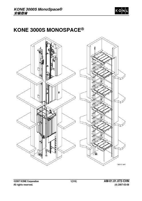
KONE 3000S MONOSPACE®©2007 KONE Corporation 1(316) AM-01.01.072-CHN保密声明为您提供该专有信息和机密文件的目的仅为安装和/或维护KONE产品。
未经过KONE相关人员的书面许可,任何人不得以任何理由,将文件泄露或拷贝给第三方翻印和外传。
对违反规定者,KONE保留违反该条例的起诉权利。
授权声明本文件的发行仅作为信息资料使用。
任何使用本文件参与安装或保养工作的人员必须具备从事该工作的资格。
要求必须接受过KONE相关具体的培训,且具备KONE授权的安装及保养资格。
免责声明KONE在任何时候均保留改变本文件中反映的产品设计、说明、程序的权利。
本文件中包含任何声明不作为对其它任何产品的、说明或程序;任何具体目的或质量;或任何购买合同的修订或表述;商品规格和适用性的依据、或条件,明示或暗示。
KONE不承担任何有关本文件所带来的任何责任。
KONE不承担任何人盲目、错误、疏忽或表述本文件所造成的后果。
本文件的使用者承担泄漏本文件的所有风险和责任。
商标声明“KONE, MonoSpace, MiniSpace, EcoDisc, TranSys, Alta, KoneXion, KONE ECO3000 和其它所有产品名称是KONE Corporation在各个国家的商标或注册商标。
”版权声明Copyright © 2007 KONE Corporation版权所有。
未获得KONE Corporation的书面许可,本文件中的任何部分均不得以任何方式和意图进行拷贝,或翻译成其它种语言格式。
©2007 KONE Corporation 2(316) AM-01.01.072-CHN目录1. 概要 (9)1.1 相关文件 (10)1.2 缩写 (11)2. 安全事项 (16)2.1. 主要安全事项 (16)2.2 安全的安装方法 (18)2.3 危险及个人防护用品标识 (19)2.4 限制发生坠落时伤害的特殊注意事项 (20)3 安装必备条件 (21)3.1 工地要求 (21)3.2 工具 (25)4. 卸货及搬运 (29)4.1 卸货及搬运物料 (29)5. 放样板线 (32)5.1 装配样板架和悬挂样板线 (32)5.2 填写样板线检查表 (35)5.3 放样板线(群组电梯) (37)6. 层门安装 (39)7 安装导轨 (40)7.1 支架组合 (40)7.2 导轨原理 (41)7.3 清洁导轨 (41)7.4 头两圈支架的标记和钻孔 (43)7.5 安装头两圈支架 (44)7.6 安装第一根轿厢导轨 (44)7.7 校准第一根轿厢导轨 (45)7.8 安装并校准第一根对重导轨 (46)7.9 其余轿厢和对重导轨的安装 (47)7.10 安装顶部导轨和支架 (48)7.11 拆除样板架 (49)7.12 对齐导轨后检查导轨的安装 (50)8 底坑内的安装 (51)8.1 安装对重框 (51)8.2 安装轿厢缓冲垫 (53)8.3 限速器张紧装置和集油器 (57)©2007 KONE Corporation 3(316) AM-01.01.072-CHN9 曳引机安装 (58)9.1 将 MX 曳引机吊装到电梯井道内 (58)9.2 将底板和顶部固定台装到顶部导轨上 (60)9.3 将曳引机放到底板上 (61)9.4 对重侧绳头 (62)9.5 轿厢侧绳头 (63)9.6 驻停板 (64)10 安装群组电梯的线槽 (65)电梯井道顶部的电气装置 (66)11. V3F16L:11.1 顶视图(V3F16L) (67)11.2 SEP和驱动板、制动器电阻器、线槽 (V3F16L) (69)11.3 曵引机电缆(V3F16L) (72)11.4 电缆:MAP – 驱动(V3F16L) (74)11.5 电缆:SEP – 驱动(V3F16L) (75)电梯井道顶部的电气装置 (76)12 V3F18:12.1 顶视图(V3F18) (77)12.2 井道电气板、驱动板和线槽(V3F18) (80)12.3 制动器电阻器 (V3F18) (82)12.4 曵引机电缆(V3F18) (83)12.5 电缆: MAP – 驱动 (V3F18) (85)12.6 电缆: SEP – 驱动 (V3F18) (86)13 称重传感器电缆,限速器电缆和电梯井道顶部照明装置 (87)14 曳引机制动器 (88)14.1 制动器松闸线 (88)14.2 制动器调节 (90)15 电缆: SEP - MAP, 主开关, 井道线束 (97)和 MAP之间的电缆 (97)15.1 SEP15.2 总电源电缆 (98)15.3 交付选项 (99)15.4 群控连接 (102)15.5 井道线束 (105)16 随行电缆 (107)17 线槽和电梯井道内的电气连接 (111)17.1 线槽和电缆固定孔 (111)17.2 井道线束 (112)17.3 电梯井道布线 (112)17.4 层站护脚板 (114)17.5 底坑电气装置 (115)©2007 KONE Corporation 4(316) AM-01.01.072-CHN18 楼层的信号装置 (117)19 校正脚手架和安装导轨夹具 (118)19.1 如何使用导轨夹具 (118)19.2 校正脚手架和安装导轨夹具 (120)19.3 将下滑轮梁吊到杆上 (121)20 安装轿厢 (122)20.1 装配立梁和底梁 (122)20.2 第二根立梁 (128)20.3 限速器的安装 (130)20.4 轿厢安全钳 (131)20.5 轿厢地板 (132)20.6 将安全踏板或安全钳自动触发绳固定到安全钳连杆 (135)20.7 轿壁 (136)20.8 玻璃壁 (140)20.9 顶梁 (144)20.10 栏杆 (145)20.11 轿顶 (148)20.12 踢板和栏杆的最后处理 (149)20.13 轿厢内部安装 (150)20.14 滑轮下梁的安装 (155)20.15 轿厢地坎 (157)20.16 安装前轿厢 (159)21 前壁安装 (162)21.1 门机的拆包和运输 (162)21.2 安装轻型门机 (163)21.3 门板缓冲垫 (165)21.4 门板紧固件 (166)21.5 门板导轨 (167)21.6 安装门板 (168)21.7 门刀 (171)21.8 导轨装置 (173)21.9 紧急打开轿厢门锁 (176)21.10 电气装置 (177)21.11 轿厢门锁和门触措施 (179)22 安装对重块 (180)23 轿厢电气装置 (182)23.1 轿厢下的随行电缆 (182)©2007 KONE Corporation 5(316) AM-01.01.072-CHN23.3 在轿顶顶部安装磁力开关 (186)23.4 轿顶电气安装 (187)23.5 接入轿顶接线盒 (189)板上的连接器 (190)23.6 LCECCB23.7 安装电梯扩音器装置 (191)23.8 在轿顶安装对讲装置 (191)23.9 光幕 (192)23.10 安装斜面和磁铁 (197)24 V3F18: 第一次不带钢丝绳驱动电动机 (199)24.1 工作中的安全与健康 (199)24.2 检查单 (200)24.3 旋转变压器,测速计和电阻器连接 (200)24.4 当以 RDF 方式第一次驱动曳引机时进行测试和检查 (202)24.5 设定驱动参数 (202)24.6 调节 TACHO 测试电位计 (204)24.7 检查 MXTORQ (204)24.8 检查旋转变压器的极性 (205)24.9 检查测速计的极性 (206)24.10 旋转变压器角度的初始设定 (207)24.11 当以检修方式第一次驱动曳引机时进行测试和检查(无钢丝绳的电梯) (209)24.12 蜂鸣器报警 (210)25 绕绳 (211)25.1 绕绳原理 (211)25.2 绕线 (212)26 拆除脚手架 (216)26.1 拆除脚手架之前进行检查 (216)26.2 拆除脚手架 (217)27 V3F16L:调试 (219)27.1 工作中的安全与健康 (219)27.2 准备工作 (220)27.3 接通电源 (222)协议 (223)27.4 LON27.5 设定驱动参数 (224)27.6 首先检查安全电路 (225)27.7 临时调整称重装置 (225)27.8 第一次驱动电梯 (226)27.9 平衡空轿厢和对重 (228)©2007 KONE Corporation 6(316) AM-01.01.072-CHN27.11 在对重中增加对重块,使负载达到额定负载的50% (231)27.12 调节称重装置 (232)27.13 对重网 (233)27.14 轿厢护脚板 (234)27.15 设置 (235)28 V3F18:最终试运行 (236)28.1 平衡空轿厢和对重 (236)28.2 绳松驰开关 (237)28.3 在对重中增加对重块,使负载达到额定负载的50% (238)协议 (240)28.4 LON28.5 称重设定 (240)28.6 对重网 (243)28.7 轿厢护脚板 (244)28.8 井道设置 (244)28.9 微调旋转变压器角度 (245)28.10 根据需要微调 (246)29 轿门调试 (250)30 最后步骤和电梯井道的清洁 (251)30.1 校正参数设置 (251)30.2 检查平层精度。
dcsf18操作手册
dcsf18操作手册一、介绍DCSF18是一种先进的控制系统,主要用于监控和管理工业自动化过程。
本操作手册旨在提供清晰的指导,以帮助用户正确地使用和操作DCSF18系统。
请在使用本系统前仔细阅读本操作手册,并按照说明进行操作。
二、系统概述DCSF18操作系统由硬件和软件两部分组成。
硬件包括主控制器、输入输出模块、传感器和执行器等,软件则基于全新开发的操作系统。
系统具备高度可靠性、稳定性和扩展性,可广泛应用于各个工业领域。
三、系统安装1. 安装硬件设备在进行系统安装之前,请确保已将所有硬件设备正确连接。
依次将主控制器、输入输出模块、传感器和执行器等设备按照连接顺序连接好,并确保连接稳固可靠。
2. 连接电源将系统所需的电源连接到主控制器上,并确保电源连接正常。
注意电源的电压与系统要求的电压符合,以避免电流过大或电流不足的问题。
四、系统启动与关闭1. 启动系统启动系统前,请确保所有相关设备正常连接并与电源连接稳固。
按下系统启动按钮,并注意系统启动过程中是否有任何异常情况出现。
如有异常情况,请立即停止启动并检查。
2. 关闭系统在关闭系统前,请确保所有的任务已经保存并退出,在系统正常运行时按下系统关闭按钮。
注意,切勿强制关闭系统,以免造成数据丢失或其他不可挽回的损失。
五、系统操作1. 界面介绍系统界面分为主界面和子界面两部分。
主界面用于显示系统的整体概况和常用操作选项,而子界面用于显示特定的功能模块和详细的操作选项。
2. 系统导航通过主界面的导航菜单可以快速进入不同的功能模块和操作选项。
在导航菜单中,用户可以根据实际需求选择相应的功能,然后跳转到对应的子界面。
3. 功能操作在子界面中进行具体的功能操作。
根据系统提供的功能选项和操作按钮,用户可以进行监控、管理和设置等操作。
在操作过程中,请注意遵循系统的提示和指导,并确保操作的准确性和稳定性。
六、故障排除1. 故障诊断当系统出现故障时,请先根据系统的报错信息进行自检。
F18 Installation guide--ZKTeco
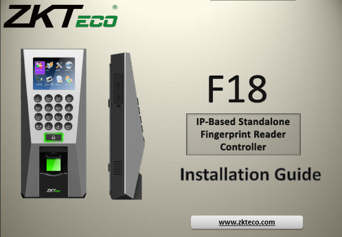
Do not place the device next to heating to let liquid like water, drinks or chemicals leak inside the device.
Clean the device often to remove dust on it
• If a finger is stained with sweat or water, scan after wiping moisture off. • If a finger is covered with dust or impurities, scan after wiping them off. • If a finger is way too dry, please blow some warm air from your mouth on the finger tip.
How to place a finger on a sensor Place a finger such that it completely covers the sensor area with maximum contact. Place core of the fingerprint at the center of the sensor. The core of a fingerprint is a center where the spiral of ridges is dense.
Power Supply Controller
Door Sensor
Electric Strike Lock
Electric Magnetic Lock
8
Product PIN Diagram
828软件使用手册
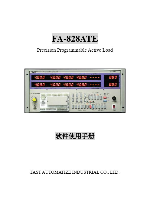
3 ADJ V
4 Setup Time
5 Hold On-AC OFF
6 Hold On-PS OFF
7 P.G. Time
说明 :结束测试项目 :负载测试项目 :电压调整项目 :S.P.S.开机时间测试(Power On Time) :S.P.S.保持时间测试(使用 AC 关闭的方式) :S.P.S.保持时间测试(使用 PS OFF 的方式) :PWR_OK Delay 延迟时间
步骤 4
(图 3)
确定信息无误后请选取 ”Next”.
(图 4)
3
FA-828ATE 软件操作手册 步骤 5
4
1 请把 ” Yes, Launch the program file “ 选项打勾(表示 Setup 完成 后,会自动开启 FA-828 ATE 程 序).
2.选取 ” Finish “ 完成 Setup 设定.
L: Link File Lower-Limit V Load Current Lower-Limit Power Load Test Delay Time
M:
6
:动态负载测试 :动态延迟(时间) :当机电压
:结束测试 :结束电流值
:档案
:测试通过 :测试没有通过
:即 AC Loss to PWR_OK Hold-up Time(保持时间,使用 AC 关闭 S.P.S 的方式)
Hold On – PS OFF
Hold-On T. Upper-L Hold-On T. Lower-L HOLD ON TIME I: Inc. Current Inc. Delay Interrupt Voltage
K: Keyboard Model Keyboard On Keyboard Lock
fe-safe2018安装教程
fe-safe2018安装教程【最新版】目录1.FE-SAFE2018 软件概述2.FE-SAFE2018 安装步骤3.FE-SAFE2018 安装注意事项4.FE-SAFE2018 软件应用领域正文一、FE-SAFE2018 软件概述FE-SAFE2018 是一款由 Autodesk 公司开发的通用有限元分析软件,适用于各种工程领域,如机械、土木、航空航天等。
它可以帮助工程师进行模型建立、网格划分、求解和后处理等,以提高设计质量和效率。
二、FE-SAFE2018 安装步骤1.下载安装包:从官方网站或其他可靠来源下载 FE-SAFE2018 安装包。
2.解压安装包:右键点击安装包,选择“解压到当前文件夹”。
3.安装软件:双击解压后的文件夹中的自解压文件,选择安装路径(建议安装在 C 盘以外的其他磁盘),然后点击确定。
4.同意安装协议:点击“我接受”,然后点击下一步。
5.安装过程:耐心等待软件安装完成。
6.启动软件:点击“立即启动”。
三、FE-SAFE2018 安装注意事项1.安装路径不能带有中文字符。
2.确保电脑满足软件的系统要求,如操作系统、内存等。
3.在安装过程中,如需输入密钥或激活码,请使用官方提供的正确密钥或激活码。
四、FE-SAFE2018 软件应用领域1.机械工程:用于分析机械零部件的强度、刚度、稳定性等。
2.土木工程:用于分析建筑物、桥梁、隧道等的结构安全性能。
3.航空航天:用于分析飞机、火箭等航空航天器的结构性能和空气动力学特性。
4.其他领域:还包括能源、交通、生物医学等众多工程领域。
总之,FE-SAFE2018 作为一款强大的有限元分析软件,广泛应用于各种工程领域,有助于提高设计质量和效率。
第1页共1页。
Soft Sides Fountains with FLEXI-GUARD 安装 维护 使用手册说明
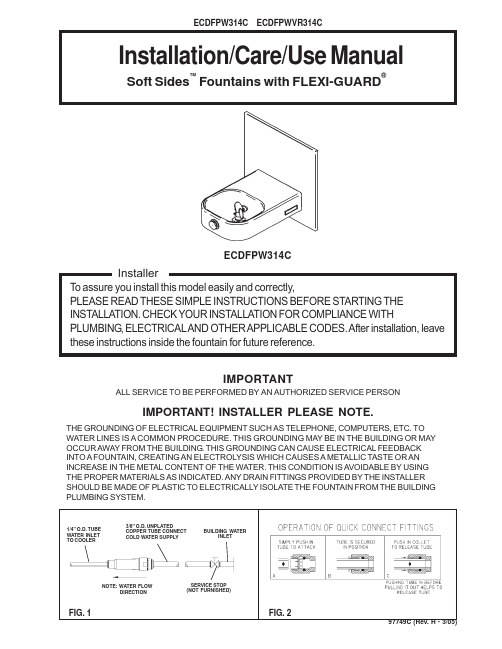
97749C (Rev. H - 3/05)Installation/Care/Use ManualSoft Sides ™Fountains with FLEXI-GUARD®IMPORTANT! INSTALLER PLEASE NOTE.THE GROUNDING OF ELECTRICAL EQUIPMENT SUCH AS TELEPHONE, COMPUTERS, ETC. TO WATER LINES IS A COMMON PROCEDURE. THIS GROUNDING MAY BE IN THE BUILDING OR MAY OCCUR AWAY FROM THE BUILDING . THIS GROUNDING CAN CAUSE ELECTRICAL FEEDBACK INTO A FOUNTAIN, CREATING AN ELECTROLYSIS WHICH CAUSES A METALLIC TASTE OR AN INCREASE IN THE METAL CONTENT OF THE WATER. THIS CONDITION IS AVOIDABLE BY USING THE PROPER MATERIALS AS INDICATED. ANY DRAIN FITTINGS PROVIDED BY THE INSTALLER SHOULD BE MADE OF PLASTIC TO ELECTRICALLY ISOLATE THE FOUNTAIN FROM THE BUILDING PLUMBING SYSTEM.IMPORTANTALL SERVICE TO BE PERFORMED BY AN AUTHORIZED SERVICE PERSONFIG. 2FIG. 1ECDFPW314CNOTE: WA TER FLOW DIRECTIONBUILDING WATER INLETSERVICE STOP (NOT FURNISHED)1/4" O.D. TUBE WA TER INLET TO COOLER3/8" O.D. UNPLATEDCOPPER TUBE CONNECT COLD WA TER SUPPLY97749C (Rev. H - 3/05)FIG. 3PAGE 2LEGENDA = RECOMMENDED WATER SUPPLY LOCATION 3/8 O.D. UNPLATEDCOPPER TUBE CONNECT STUBBED 1-1/2" (38mm) FROM WALL SHUT OFF BY OTHERSB = RECOMMENDED LOCATION FOR WASTE OUTLET 1-1/4" O.D. DRAINC = 1-1/4" DRAIN FURNISHEDD = OPENING FOR OPTIONAL AP-99 ACCESS PANEL.NOTE: REINFORCE THE WALL IN THE SHADED AREASECDFPW314CINSTALLATION INSTRUCTIONS1. Wall should already be framed for the fountain using the positioning dimensions shown in Figure 3. Showndimensions pertain to installation location (framing must support up to 300 lbs. weight). These dimensionsare required for compliance with ANSI Standard A117.0.2. Attach wall plate assembly to wall as shown in Figure 3 using 5/16" x 2" long bolts and flat washers(not provided). Tighten securely. (Fastener must match wall type, i.e. lag screws for wood studs, bolts andanchors for masonary construction.)3. Install back panel. Place the upper edge of the panel above hanger on the wall. Slide panel down until itengages the hanger. Be sure back panel is firmly engaged before releasing it.4. Install rough-in plumbing as shown in Figure 3. Waste line should extend a minimum of 2" (51mm) thru theback panel. Run supply water inlet line thru back panel. Install a service stop (not provided). Turn on supplywater and flush thoroughly.5. Remove bottom access panel from fountain basin and save the screws. Install the fountain to the backpanel using (4) 5/16" x 3/4" long screws and washers (provided) thru holes in back panel. Tighten securely.6. Cut waste tube to required length using plumbing hardware and a trap (not provided) as a guide. Installhardware and trap. Tighten securely.7. Make water supply connections from service stop to the 3/8" O.D. unplated copper tube coming out of thefountain strainer (See Fig. 1). Turn on water supply and check for leaks. Newly installed water supply lineshould be insulated after leak check is completed. DO NOT SOLDER TUBES INSERTED INTO THE STRAINERAS DAMAGE TO THE O-RINGS MAY RESULT.8. These products are designed to operate on 20-105 PSIG supply line pressure. If inlet pressure is above105 PSIG, a pressure regulator must be installed in the supply line. Any damage caused by reason ofconnecting these products to supply line pressure lower than 20 PSIG or higher than 105 PSIG is notcovered by warranty.9. Check stream height from bubbler. Stream height is factory set at 35 PSI. If supply pressure varies greatlyfrom this, adjust the screw on regulator item 10 by using a small screwdriver through the small holein the push button item 3 (See Fig.5). Clockwise adjustment will raise stream height and counter-clockwiseadjustment will lower stream height. For best adjustment stream should hit basin approximately 6-1/2"(165mm) from bubbler.10. Replace bottom access panel to fountain basin using screws provided. Tighten securely.TROUBLE SHOOTING AND MAINTENANCE1. Orifice Assy: Mineral deposits on orifice can cause water flow to spurt or not regulate. Mineral depositsmay be removed from orifice with a small round file not over 1/8" diameter or a small diameter wire.CAUTION: Do not file or cut orifice materials.2. Stream Regulator: If orifice is free of material deposits, regulate flow according to instruction 9 stated above.3. Actuation of Quick Connect Water Fittings: Cooler is provided with lead-free connectors which utilize ano-ring water seal. To remove tubing from the fitting, relieve water pressure, push in on the gray collar whilepulling on the tubing (See Figure 2). To insert tubing, push tube straight into the fitting until it reaches apositive stop, approximately 3/4".97749C (Rev. H - 3/05)PAGE 397749C (Rev. H - 3/05)PAGE 4P ART NO.ITEM NO.PARTS LISTDrain - Strainer Retaining Nut Push ButtonPush Button Sleeve Regulator Holder Orifice Assy Housing Assy PedestalBubbler Locknut Regulator Cap ScrewScrew - #10-24 X .50 PHTC StrainerFountain Arm - LongBottom Cover Plate - Long Back Panel Hex NutRegulator Mounting Bracket Gasket (VR Model Only)Bubbler - Nipple (VR Model Only)Bubbler (VR Model Only)Poly Tubing (Cut To Length)Mounting Plate Assy Drain Tailpipe Drain Adapter Gasket - T ail Pipe Tube - Water InNut-Regulator MountingWasher - Flat .339/.359ID Steel Screw - Mach. 5/16-18 x 3/440575C 15005C 45662C 45737C 50986C 40322C 56011C 55997C 75580C 61313C 75672C 11262754389055996C 550011295500066528290C 40045C 28291C 10032274056015009C 45392C 56092C 28286C 45679C 45805C 50074C 60295C 45736C 75541C 111577243890123456789101112131415161718192021222324252627282930DESCRIPTIONFIG. 8NOTE: WHEN INSTALLING REPLACEMENT BUBBLER AND PEDESTAL, TIGHTEN NUT (ITEM 9 OR 20) ONLY TO HOLD PARTS SNUG IN POSITION. DO NOT OVER TIGHTEN.FIG. 6172105341814SEE FIG. 6 OR 716SEE FIG. 5151,24,25,26137896FIG. 5192021FIG. 72223272829, 301211 800-518-5388。
f18加装倒车影像 (5)

BMW Workshop Equipment And Special Tools Page 15
倒车影像系统电路图
BMW Workshop Equipment And Special Tools Page 16
倒车影像系统安装和接线图
BMW Workshop Equipment And Special Tools Page 17
加装步骤
• 将电线束经转向柱上方与仪 表板内的车身线束固定好并 与CIC供电线束捆绑在一起
将RGB导线连接至CIC插头内 - RT电缆,至针脚18 - WS电缆,至针脚28 -屏蔽,至针脚27 用小连接器连接K-CAN总线 - OR/GN电缆,至针脚11的同色电缆 - GN电缆,至针脚9的同色电缆
BMW Workshop Equipment And Special Tools Page 12
• 将控制单元与之家安装到行李箱中并使用螺栓固定好
BMW Workshop Equipment And Special Tools Page 7
加装步骤
安装并连接改装电缆
• 布设RGB、K-CAN及模块供电线缆
BMW Workshop Equipment And Special Tools Page 8
加装步骤
• 注意摄像头电缆B的布线。 当开启或关闭后备箱时,电缆不应 扭结或拉伸。 • 用带夹子H的电缆扎带将摄像头电缆B固定到尾门铰链(1)和 侧围(2)上。
BMW Workshop Equipment And Special Tools Page 6
加装步骤
• 安装环视摄像机模块支架
• 注:如果已在车中安装了支架,则不再需要。
BMW Workshop Equipment And Special Tools Page 1
中控门禁F18安装指南V1.1

3. TCP/IP通讯方式
端子定义见右表: 两种连接方式如下: (1) 设备与电脑通过交叉网线直接连接。
端子名称 RJ45-1 RJ45-2 RJ45-3 RJ45-6
线序 TX+ TXRX+ RX-
颜色 白橙 橙 白绿 绿
1. 设备到门禁控制器或读卡器的距离建议不超过90米(如需传输距离更长或使用环境中有干扰时, 请使用Wiegand信号延长器)。 2. 不论设备是否与门禁控制器或读卡器共用电源,都必须确保设备与门禁控制器或读卡器共地,以 保证Wiegand信号稳定。
+
DC12V
FR 107
+
+
-
11
+
-
FR 107
+12V GND BELLBELL+ SEN GND BUT NO1 COM1 NC1 NO2 COM2
设备与锁不共用电源情况: 1)ULOCK=12V 且 I-ILOCK≤1A; 2)ULOCK≠12V; 3)锁与设备之间距离>10 米时。
-
五、连接电源
F18 安装指南
一、安装设备
版本:V1.1
日期:2011年11月
三、连接门锁
1. 设备与锁共用电源
+ +
!
警告:请勿带电接线!
布线孔
+12V GND BELLBELL+ SEN GND BUT NO1 COM1 NC1 NO2 COM2
DC12V
+
+12V GND BELLBELL+ SEN GND BUT NO1 COM1 NC1 NO2 COM2
-
+
4 . 将 铁板的螺丝孔位对准墙面上 5. 拧紧底部螺丝,将设备固定在 钻好 的孔位,用螺丝将 胶垫和 铁板上 铁板固定在墙上
美福2008操作系统安装手册
服务器安装安装系统环境安装Windows2008 64位操作系统。
安装TTS引擎1) 关闭数据执行保护,并重启机器。
2) 安装InterPhonic 6.0系统(6700-HASP HL版本.密码:PTLAWX-GXEPD6-W3AHED)。
3)音库安装小芮音库,位置TTS\音库\VocLib16K_xiaorui。
4)cy2008定制包安装,位置TTS\CY2008定制包。
2.拷贝小芮提示音库到相应目录:●拷贝TTS\提示音库\王如提示音\VptLib.be替换C:\Program Files\iFly InfoTek\InterPhonic 6.0\resource\cy2008目录下的VptLib.be文件●拷贝TTS\提示音库\王如提示音库\VptAudio\wangru至C:\Program Files\iFlyInfo Tek\InterPhonic 6.0\resource\cy2008\VptAudio目录下修改TTS安装目录bin\isp目录下ses.cfg和spi.cfg配置文件。
svc_only = false修改为svc_only = true3.设置ses服务为自启动并启动ses(Speech Engine Service)服务,至此TTS引擎及音库安装完成。
4. 安装所需软件1)安装IIS2)安装Dotnetfx35.exe,安装完成后运行命令:(%windir%\\Framework\v2.0.50727\aspnet_regiis –i)安装数据库(使用SQL安装程序完整安装,sa用户对应的密码iflytek!234)安装SQL2005数据库,在DataBase目录下:1)安装isay365_lan数据库●新建isay365_lan数据库●执行i say365_lan.sql,位置DataBase\isay365_lan.sql2)安装PsciManager数据库●新建PsciManager数据库●执行PsciManager.sql,位置DataBase\PsciManager.sql3)对isay365_lan数据库执行isay365_lan_Add.sql脚本如果有安装包,即可从此处安装直至完成.部署WEB网站1.分别对APP,Service,systemweb三个网站建立应用程序池,打开IIS右键‘应用程序池’—添加应用程序池-分别以网站命名2.对已经建立的三个应用程序池,进行设置,设置如下:右键硬件应用程序池名,选择高级设置,将‘启用32位应用程序’对应的值 False 修改为True,三个应用程序池分别都进行此设置3.建立网站在IIS中新建网站SystemWeb,网站端口80,路径指向WebSite\web\SystemWeb3.1.1新建虚拟目录ManagerWeb,指向WebSite\web\ManagerWeb3.1.2新建虚拟目录TransactFileService,指向WebSite\service\TransactFileService3.1.3新建虚拟目录ttsFile,指向WebSite\service\TTSWebService\ecl_ttswave\standard\PromisStudy,3.2 新建文件夹APP(建于WebSite同级目录),在IIS中新建网站APP,路径指向新建的APP文件夹,网站端口88。
WM013922R0102_WinControl_1800安装与指导手册

F10 F18

仅限配备视频开关的车辆(原装或改装)
不需要
A42*1B 针脚 28
仅限未配备视频开关的车辆
至 CIC A9 A10 插座触点 眼环接线片 M6 端子 15 端子 31 GN/BL 0.50 mm2 BR 0.50 mm2 至左侧行李箱内的接地支撑点 连接到右后配电盒
A42*1B 针脚 27 Z2*10B 针脚 2 Z10*12B
© BMW AG, Munich
01 29 2 181 352
3/2010
(Z/Z)
3
1.
倒车影像系统配件列表
图例 A B C D E F G H I J K L I N O 改装电缆 摄像头电缆 控制单元(未包含在改装套件中) 倒车影像系统控制单元支承 尾门按钮 放大器支承 摄像头 带卡扣的扎带(5条) 六角螺母M5(4个) 六角螺母M6(2个) 扎带(20条) 5 A保险丝 小连接器(2个) 六角螺钉M6(2个) 金属板螺母M6
原装BMW附件 安装说明
倒车影像系统改装 BMW 5系( F10、 F18)
改装套件编号
66 21 2 181 317 65 12 2 182 508
倒车影像系统改装套件 视频开关改装套件
安装时间 安装时间约为4.5 小时。如果需要安装视频开关改装套件,安装时间将延长约1.5小时。 由于汽车状态及其内部 装备的不同,安装时间可能会有所变化。
规定的安装时间不包括编程/编码所使用的时间。 计算改装费用时,应将编程时间的总费用考虑在内(不允许通过保修补偿)。
重要信息 这些安装说明主要供BMW经销商组织和授权 BMW售后服务公司使用。 在任何情况下,本安装说明所针对的目标群体均是经过BMW车辆知识培训并具有相应专业知识的专业人员。 必须使用最新的BMW修理手册、电路图、保养手册和工作说明以合理的顺序完成所有工作,在完成工作的过程 中还必须使用指定的工具(专用工具)并遵守当前的安全规定。 如果出现任何安装或功能问题,对于机械工作来说,故障查找时间限制在大约0.5小时之内;对于电气工作则限 制在大约1小时之内。 为了降低成本和防止产生任何额外费用,立即通过BMW售后服务帮助网站(ASAP)向技术部件支持部门发送查 询请求。 明确说明以下信息: - 底盘号 - 改装套件的配件号 - 对问题进行准确描述 - 已执行的操作步骤 由于需要通过ASAP进行每日更新,所以请不要将这些安装指导的硬拷贝归档!
技术附件

技术附件(1)设备设计方案、技术附件(含技术参数、设备描述及说明)1机车简介JMY600F18(B)型内燃机车是江苏今创车辆有限公司设计制造的工矿调车型内燃机车。
该机车构造速度为30km/h。
通过最小曲线半径为50米,整备重量为64吨、机车上装有一台重庆康明斯KTA19-L600柴油机,主传动装置是由江苏今创车辆有限公司生产制造的DEL1448FXI 2B型液力变扭箱。
采用了较先进的液力换向,电子自动换档、PLC、低匀速控制等技术,具有起动牵引力大、制动力强,通过曲线半径小,换向迅速等优点,特别适合于我国各工矿企业以及地方、森林、港口、铁路的调车及小运转作业。
1.1机车布置本机车为准轨调车型内燃机车,整个机车由车体、车架和前后二只两轴转向架组成。
1.1.1车体及内部设备布置本机车车体采用了调车型机车常用的罩式车体,一个司机室设在机车中部,前后分别是动力室(长的一端)后机室(短的一端)。
靠动力室的左角设置了一个司机操纵台,采用了前窗了望,具有了望方便,特别适合于调车作业的特点。
在司机室前右、后左都设车门,便于乘务员上下机车及检修机车。
走台设在动力室、后机室两侧,呈外走廊式。
从司机室可通过外走道直接到达动力室、后机室的每一个部位。
动力室、后机室开了一些门,可方便地检修其内部的机器设备,动力室、司机室、后机室之间夹有防雨橡皮条且均用螺栓联接。
司机室内靠动力室左角设置操纵台,台上装有无级调速主控制器,JZ-7型自动制动阀,各种电气控制开关,各种检测仪表,以及显示、报警用各类指示灯,操纵台右面板上装有手制动轮,司机室顶部安装冷暖空调(提供两种方案供客户选择)。
在正司机操纵台下踏板上装有撒砂、风笛脚踏开关,副司机座椅旁侧壁上装有风笛按钮,电气柜装置在操纵台旁。
动力室是本机车的主机器间,机车上各主要动力传动部件均安装在此,整个动力室顶盖为活动天灵盖型,松开连接螺栓就可掀起,以便于吊出柴油机、变扭箱等大部件进行维修,动力室内从前往后依次装有风扇齿轮箱(冷却室内、冷却风扇下)、万向轴。
6180工业计算机附属设备安装指南
Accessory Mounting Brackets and Covers (For 6180 Industrial Computers)This instruction sheets provides installation instructions for the following accessory brackets and covers.The catalog numbers identify Series B parts by adding “B” to the end of the catalog number.Make sure the series letter of your computer is appropriate for the brackets.y When a catalog number for a bracket does not have a letter “B” at the end, that bracket applies to Series A and Series B units.InstructionsCovers and BracketsAccessory Mounting Brackets and Covers2The lower bay mounting bracket (Catalog No. 6189-LBFDBRKT)allows you to mount a floppy drive facing either the front or the back of the 6180 computer as shown below.•Mounting Bracket for Lower Bay Floppy Drive(Catalog No. 6189-LBFDBRKT for Series A and B)InstallationNote: You can also use these procedures to intstall a front or rear facing CDROM drive (without mounting bracket). The lower bay floppy drive mounting bracket and CDROM drive use the same sets of chassis mounting holes.To install a floppy using the lower bay mounting bracket:1.Secure the floppy drive to the drive bracket using four screwssupplied with the bracket. Tighten screws to a torque of 6-8 in.lbs (.7-.9 N S m).Drive Mounting Screws (4)Floppy Drive Lower Bay Mounting BracketAccessory Mounting Brackets and Covers3!ATTENTION: Remove all cables from the side panel connectors. Failure to remove cables may cause damage to the cables and connectors.!ATTENTION: If the 6180 Computer is installed with mounting clips, the mounting clips on the hinge side will interfere with the opening of the hinge. Remove the mounting clips on the hinge side before swinging chassis away from the bezel. Failure to remove clips may damage clips and the chassis.2.Swing open the back of the computer chassis after removing thethree bezel latching screws. Refer to 6180 computer user manual for instructions if required.From Bezel for Rear Mounting of Drive3.Position the accessory drive / bracket assembly into the chassis.Notes:For rear facing drives, you may have to remove the panelknockout (shown above) if a rear mounted drive was notpreviously installed. Insert screwdriver into slot on knockouts and pry back and forth on knockout to remove. Use a pliers to remove the center rib between the two knockouts.For front facing drives, if a floppy drive was not previouslyinstalled, you may have to replace the floppy drive cover behind the front access door with a cover having an opening. Refer to Floppy Drive Front Cover on page 7 for a description of theavailable covers.Accessory Mounting Brackets and Covers4 4.Connect the cable connectors to the floppy drive. Connectors arekeyed so they cannot be installed backwards.5.Align the floppy drive/bracket (or CDROM) and chassismounting holes and secure the with the 4 mounting screwsprovided with the bracket (or CDROM). Tighten screws to a torque of 6-8 in. lbs (.7-.9 N S m).Use these chassis holes for both rear andfront mounting of a floppy drive. For frontaccess mounting, use the rear hole pairs onthe mounting bracket. For rear accessmounting, use the front hole pairs on themounting bracket.For front access mounting of a CDROM drive, use chassis hole pairs 2 and 5 and the front hole pairs on the CDROM.For Floppy Drive/Bracket AssemblyFor CDROM Drive235For rear access mounting of a CDROMdrive, use chassis holes 3 and the rear holepair on the CDROM.6.Swing the chassis back onto the bezel and secure chassis with thethree latching screws. Tighten screws to a torque of 18-22 inch lbs (2-2.5 N S m).7.Install the back panel.8.Apply power to the 6180 Computer and verify operation of thedrive. You may need to edit BIOS settings to recognize the drive or to allow the operating system to detect the new hardware.Accessory Mounting Brackets and Covers 5The upper bay mounting bracket allows you to mount a floppy driveout the side of the 6180 computer chassis.•Mounting Bracket for Upper Bay Floppy Drive(Catalog No. 6189-UBFDBRKT for Series A; Catalog No.6189–UBFDBRKTB for Series B)InstallationTo install a floppy using the upper bay mounting bracket:1.Secure the floppy drive to the drive bracket using four screwssupplied with the drive. Tighten screws to a torque of 6-8 in. lbs (.7-.9 N S m).Floppy Drive Upper Bay Mounting BracketAccessory Mounting Brackets and Covers62.Remove the back panel to the 6180 computer.3. A shorter drive cable is provided with the mounting kit formounting in the upper bay. Connect the cable to the floppy driveconnector on the processor board (refer to the Processor Boarduser manual if necessary) and the connector on the back of thedrive.4.Position the accessory drive / bracket assembly into the chassis.The edge of the bracket fits under the tab at the front of thechassis.Note: You may have to remove the side panel knockout (shownbelow) if a side mounted drive was not previously installed.Insert screwdriver into slot on knockouts and pry back and forthon knockout to remove. Use a pliers to remove the center ribbetween the two knockouts.!ATTENTION: If knockout is removed, carefully remove any burrs or sharp edges. Failure to remove sharp edges could result in personal injury.5.Align the bracket and chassis mounting hole and secure the drive/ bracket assembly with a mounting screw. Tighten screw to a torque of 6-8 in. lbs (.7-.9 N S m).6.Install the back panel.7.Apply power to the 6180 Computer and verify operation of thedrive. You may need to edit BIOS settings to recognize the drive or to allow the operating system to detect the new hardware.Accessory Mounting Brackets and Covers 7The floppy drive cover plates provide protection for installed floppydrives.•Floppy Drive Cover Plates(Catalog No. 6189-FDDCVR for Series A;Catalog No. 6189-FDDCVRB for Series B)There are four floppy drive cover plates (2 front covers, 2 rearcovers). Use the cover plates as follows:Use this front cover when Floppy Drive is front mounted.The cover mounts under the front access door to protectthe front of the floppy drive.Use this front cover when Floppy Drive is rear mounted ornot installed. The cover mounts under the front accessdoor to protect the rear of the floppy drive or to preventaccess to the inside of the computer.Use this rear cover when front mounting a floppy drive orif a floppy drive is not installed.Use this rear cover when a floppy drive is rear mounted.To install the rear cover plate:1.Remove the back panel to the 6180 computer.2.Position the cover on the inside of the back panel.3.Secure the cover with the screw provided. Tighten screw to atorque of 6-8 in. lbs (.7-.9 N S m).4.Install the back panel on the 6180 computer.Floppy Drive Cover PlatesAccessory Mounting Brackets and Covers8To install a front cover:!ATTENTION: If the 6180 Computer is installed with mounting clips, the mounting clips on the hinge side will interfere with the opening of the hinge. Remove the mounting clips on the hinge side before swinging chassis away from the bezel. Failure to remove clips may damage clips and the chassis.!ATTENTION: Remove all cables from the the side panel connectors. Failure to remove cables may cause damage to the cables and connectors.1.Swing open the back of the computer chassis after removing thethree bezel latching screws. Refer to 6180 computer user manual for instructions if required.From BezelAccessory Mounting Brackets and Covers9 2.Position the front cover inside the front bezel assembly andsecure with the screw provided. Tighten screw to a torque of 6-8 in. lbs (.7-.9 N S m).3.Swing the chassis back onto the bezel and secure chassis with thethree latching screws. Tighten screws to a torque of 18-22 inch lbs (2-2.5 N S m).Accessory Mounting Brackets and Covers10The hard drive mounting brackets allow you to mount a 3.5 inchdrive in one of the drive bays of the 6180 computer chassis.•Mounting Bracket for 3.5 Inch Drives(Catalog No. 6189-IB35BRKT for Series A and B)InstallationTo install a drive using the hard drive mounting bracket:1.Secure the drive to the bracket with the four mounting screws.Tighten screw to a torque of 6-8 in. lbs (.7-.9 N S m).2.Position the drive / bracket assembly into the chassis. Make surethe hook on the bracket slide into the corresponding hole in the chassis. Also make sure that the key on the end of the bracket is inserted into the slot on the chassis front panel.3.Secure the drive / bracket assembly to the chassis with the twomounting screws. Tighten screw to a torque of 6-8 in. lbs (.7-.9N S m).3.5 Inch Hard Drive Mounting Bracket4.Install the ribbon connector on the hard drive. On 3.5 inch drivesalso connect the power cable. Make sure that the ribbon cable is installed correctly. The red wire of the cable must be at thebottom as shown below:5.Install the back panel.6.Apply power to the 6180 Computer and verify operation of thedrive. You may need to edit BIOS settings to recognize the drive or to allow the operating system to detect the new hardware.The solid state drive mounting brackets allow you to mount a 2.5inch or solid state drive in one of the drive bays of the 6180computer chassis.•Mounting Bracket for 2.5 Inch or Solid State Drives(Catalog No. 6189-IBSDBRKT for Series A and B)InstallationTo install a drive using the solid state drive mounting bracket:1.Secure the drive to the bracket with the four mounting screws.Tighten screw to a torque of 6-8 in. lbs (.7-.9 N S m).Important: If you are installing a 2.5 inch drive, you must removethe four standoffs and mount the drive directly to the bracket. Usethe mounting screws provided with the drive.2.Position the drive / bracket assembly into the chassis. Make surethe hook on the bracket slides into the corresponding hole in thechassis. Also make sure that the key on the end of the bracket isinserted into the slot on the chassis front panel.3.Secure the drive / bracket assembly to the chassis with the twomounting screws. Tighten screw to a torque of 6-8 in. lbs (.7-.9N S m).2.5 Inch/Solid State Drive Mounting Brackets4.Install the IDE converter board (provided with bracket) on thetwo standoffs on the left side of the drive bays. The converterboard snaps on to the standoffs, no hardware is required.IDE Converter Board5.Connect the shorter processor board IDE cable (provided withbracket) and power connector to the IDE converter board.IDE Cable From ProcessorBoard Connects HerePower Supply Cable for Drive Connects Here.6.Connect the drive ribbon cable (provided with bracket) to the IDEconverter board and the drive. The red wire of the cable must be at the bottom as shown below:7.Install the back panel.8.Apply power to the 6180 Computer and verify operation of thedrive. You may need to edit BIOS settings to recognize the drive or to allow the operating system to detect the new hardware.The CD ROM covers provide protection for the part of the drive thatextends from the 6180 computer chassis. Two cover kits areavailable:•Cover Kit for Front Mounting of CD ROM(Catalog No. 6189-FCDBRKT for Series A;Catalog No. 6189-FCDBRKTB for Series B)•Cover Kit for Rear Mounting of CD ROM(Catalog No. 6189-RCDBRKT for Series A;Catalog No. 6189-RCDBRKTB for Series B)InstallationNote: There are two bags of screws provided with the bracket. Usethe three flush head mounting screws to mount the covers. Use theremaining four screws to secure the CD ROM drive.Use this front cover when a CD Drive is rear mounted.The cover mounts under the front access door to protectthe rear of the CD drive.Use this rear cover when a CD Drive is rear mounted.The cover mounts to the back panel to protect the front ofthe CD drive while allowing access to the drive.Catalog No. 6189-RCDBRKTCatalog No. 6189-RCDBRKTBCatalog No. 6189-FCDBRKTCatalog No. 6189-FCDBRKTB Use this rear cover when a CD Drive is front mounted.The cover mounts on the back panel to protect the rearof the CD drive.To install a rear cover:1.Remove the back panel to the 6180 computer.2.Position the cover on the inside of the back panel.3.Secure the cover with the screw provided. Tighten screw to atorque of 6-8 in. lbs (.7-.9 N S m).4.Install the back panel.To install a front cover , refer to the instructions on page 8.To install a CD ROM , refer to the instructions on page 4.CD ROM CoversAllen-Bradley, a Rockwell Automation Business, has been helping its customers improveproductivity and quality for more than 90 years. We design, manufacture and support a broadrange of automation products worldwide. They include logic processors, power and motioncontrol devices, operator interfaces, sensors and a variety of software. Rockwell is one of theWorldwide representation.Argentina • Australia • Austria • Bahrain • Belgium • Brazil • Bulgaria • Canada • Chile • China, PRC • Colombia • Costa Rica • Croatia • Cyprus • Czech Republic • Denmark •Ecuador • Egypt • El Salvador • Finland • France • Germany • Greece • Guatemala • Honduras • Hong Kong • Hungary • Iceland • India • Indonesia • Ireland •Israel • Italy •Jamaica • Japan • Jordan • Korea • Kuwait • Lebanon • Malaysia • Mexico • Netherlands •New Zealand • Norway • Pakistan • Peru • Philippines • Poland • Portugal • Puerto Rico • Qatar • Romania • Russia–CIS • Saudi Arabia • Singapore • Slovakia • Slovenia • South Africa, Republic • Spain • Sweden •Switzerland • Taiwan • Thailand • Turkey •United Arab Emirates • United Kingdom • United States • Uruguay • Venezuela • YugoslaviaAllen-Bradley Headquarters, 1201 South Second Street, Milwaukee, WI 53204 USA, Tel: (1) 414 382-2000 Fax: (1) 414 382-444441061-042-01(D)Copyright 1998 Allen-Bradley Company, Inc. Printed in USA。
2010一汽大众高尔夫Golf A6电路图 3月版
服务修理手册A6 2010 ➤1接地点1.1发动机舱内接地点一览656 - 接地点,在右大灯上❑拧紧力矩:9Nm❑安装位置: ⇒ 页 2609 - 接地点,在排水槽内右侧❑拧紧力矩:9Nm❑安装位置: ⇒ 页 2❑未占用607 - 接地点,在排水槽内左侧❑拧紧力矩:9Nm❑安装位置: ⇒ 页 31 - 接地线、蓄电池-车身❑拧紧力矩:9Nm❑安装位置: ⇒ 页 3615 - 接地点,在左侧减震支柱上❑拧紧力矩:9Nm❑安装位置: ⇒ 页 3655 - 接地点,在左大灯上❑拧紧力矩:9Nm❑安装位置: ⇒ 页 4642 - EC 风扇接地点❑拧紧力矩:9Nm❑安装位置: ⇒ 页 4652 - 变速箱和发动机接地的接地点❑拧紧力矩:9Nm❑安装位置: ⇒ 页 418 - 接地点,在发动机缸体上❑拧紧力矩:15Nm❑安装位置: ⇒ 页 515 - 气缸盖上的接地点-箭头-❑拧紧力矩:9Nm❑安装位置: ⇒ 页 5656 - 接地点,在右大灯上-箭头-609 - 接地点,在排水槽内右侧-箭头-(未占用)1 - 接地线、蓄电池—车身-箭头 A-615 - 接地点,在左侧减震支柱上-箭头 B-642 - EC 风扇接地点-箭头 B-652 - 变速箱和发动机接地的接地点-箭头 A-18 - 发动机缸体上接地点-箭头-15 - 发动机缸盖上接地点-箭头-1.2车内接地点一览43 - 接地点,右侧 A 柱下部❑拧紧力矩:9Nm❑安装位置: ⇒ 页 747 - 接地点,在右前脚部空间内❑拧紧力矩:9Nm❑安装位置: ⇒ 页 7610 - 接地点(音频),在前部中控台下方❑拧紧力矩:9Nm❑安装位置: ⇒ 页 7602 - 接地点,在左前脚部空间内❑拧紧力矩:9Nm❑安装位置: ⇒ 页 844 - 接地点,左侧 A 柱下部❑拧紧力矩:9Nm❑安装位置: ⇒ 页 8605 - 接地点,在转向柱上部❑拧紧力矩:9Nm❑安装位置: ⇒ 页 843 - 接地点,右侧 A 柱下部-箭头 A-47 - 接地点,在右前脚部空间内-箭头 B-610 - 接地点(音频),在前部中控台下方-箭头-602 - 接地点,在左前脚部空间内-箭头 B-44 - 接地点,左侧 A 柱下部-箭头 A-605 - 接地点,在转向柱上部-箭头-1.3行李箱内接地点一览681 - 接地点 1,在右后侧围板内-箭头-❑安装位置 ⇒ 页 10682 - 接地点 2,在右后侧围板内-箭头-❑安装位置 ⇒ 页 1053 - 接地点,在行李箱盖内上部-箭头-❑安装位置 ⇒ 页 10679 - 接地点 2,在左后侧围板内❑安装位置 ⇒ 页 11682 - 接地点 2,在右后侧围板内-箭头-53 - 接地点,在行李箱盖内上部-箭头-1保险丝1.1保险丝(SA)、(SB)、(SC)一览1 - 保险丝架 A 上的保险丝(SA)❑电控箱 Low 安装位置 ⇒ 页 2❑电控箱 Low 保险丝位置分配 ⇒ 页 32 - 保险丝架 B 上的保险丝(SB)❑电控箱 Low 安装位置 ⇒ 页 4❑电控箱 Low 保险丝位置分配 ⇒ 页 43 - 保险丝架 C 上的保险丝(SC)❑电控箱 Low 安装位置 ⇒ 页 7❑电控箱 Low 保险丝位置分配 ⇒ 页 84 - 热敏保险丝,在仪表板左下方❑安装位置 驾驶员座椅调节装置热敏保险丝 1 -S44- ⇒ 页 111.2保险丝(SA)的安装位置,在电控箱 Low 上拧紧力矩=>电气设备;维修组 97;拆卸和安装保险丝架保险丝颜色200 A - 黑色150 A - 黑色125 A - 黑色100 A - 黑色80 A - 黑色70 A - 黑色60 A - 黑色50 A - 黑色40 A - 黑色30 A - 黑色1.2.1电控箱 Low 保险丝位置分配编号电路图中的名称额定值功能/部件接线端1B保险丝架 A 上的保险丝 1 -SA1-150A200A -三相交流发电机 -C- (90A/120A)三相交流发电机 -C- (140A)30a2C保险丝架 A 上的保险丝 2 -SA2-80A-助力转向控制单元 -J500-电控机械式助力转向器电机 -V187-30a3E保险丝架 A 上的保险丝 3 -SA3-50A-散热器风扇控制单元 -J293-散热器风扇 -V7-散热器风扇 2 -V177-30a4H保险丝架 A 上的保险丝 4 -SA4---未占用-5D保险丝架 A 上的保险丝 5 -SA5-80A-车内保险丝插座接线端 3030a 6F保险丝架 A 上的保险丝 6 -SA6--未占用-7G保险丝架 A 上的保险丝 7 -SA7---未占用-1.3保险丝(SB),在电控箱 Low 上,在发动机舱内左侧- 保险丝颜色50 A - 红色40 A - 橙色30 A - 淡绿色25 A - 天然色(白色)20 A - 黄色15 A - 淡蓝色10 A - 红色7.5 A - 棕色5 A - 浅褐色1.3.1电控箱 Low 保险丝位置分配编电路图中的名称额定值功能/部件接线端号F1-保险丝架 B 上的保险丝 1 -SB1---未占用-F2-保险丝架 B 上的保险丝 2 -SB2-30A-自动变速箱机械电子单元 -J743- 1)30a F3-保险丝架 B 上的保险丝 3 -SB3-5A-车载电网控制单元 -J519-30a F4-保险丝架 B 上的保险丝 4 -SB4-30A-ABS 控制单元 -J104-30a F5-保险丝架 B 上的保险丝 5 -SB5-15A-自动变速箱机械电子单元 -J743- 1)30a F6-保险丝架 B 上的保险丝 6 -SB6-5A-组合仪表控制单元 -J285-转向柱电子装置控制单元 -J527-30a F7-保险丝架 B 上的保险丝 7 -SB7-40A-接线端 15 供电继电器 -J329-30a F8-保险丝架 B 上的保险丝 8 -SB8-15A-收音机 -R-带收音机和导航系统显示单元的控制单元 -J503-外部多媒体设备接口 -R215-30aF9-保险丝架 B 上的保险丝 9 -SB9---未占用-F10-保险丝架 B 上的保险丝 10 -SB10-5A-发动机控制单元 -J623- 2)Motronic 供电继电器 -J271- 2)端子 30 供电继电器 -J317- 3)发动机控制单元 -J220- 3)30aF11-保险丝架 B 上的保险丝 11 -SB11---未占用-F12-保险丝架 B 上的保险丝 12 -SB12-5A-数据总线诊断接口 -J533-30aF13-保险丝架 B 上的保险丝 13 -SB13-15A30A -发动机控制单元 -J623- 2)发动机控制单元 -J220- 3)87aF14-保险丝架 B 上的保险丝 14 -SB14-20A-带功率输出级的点火线圈 1 -N70-87a带功率输出级的点火线圈 2 -N127-带功率输出级的点火线圈 3 -N291-带功率输出级的点火线圈 4 -N292-F15-保险丝架 B 上的保险丝 15 -SB15-10A-氧传感器加热装置 -Z19- 2)尾气催化净化器后的氧传感器 1 加热装置 -Z29- 2)气缸 1 喷油阀 -N30- 3)气缸 2 喷油阀 -N31- 3)气缸 3 喷油阀 -N32- 3)气缸 4 喷油阀 -N33- 3)87aF16-保险丝架 B 上的保险丝 16 -SB16-30A-左侧停车灯 -M4-左后转向信号灯 -M6-右前转向信号灯 -M7-右侧倒车灯 -M17-左侧制动灯 -M21-右侧近光灯 -M31-右侧远光灯 -M32-右侧前雾灯 -L23-牌照灯 -x-30aF17-保险丝架 B 上的保险丝 17 -SB17-15A-双音喇叭继电器 -J4-30a F18-保险丝架 B 上的保险丝 18 -SB18---未占用-F19-保险丝架 B 上的保险丝 19 -SB19-30A-车窗玻璃刮水器电机 -V-30a F20-保险丝架 B 上的保险丝 20 -SB20-10A冷却液循环泵 -V50-30aF21-保险丝架 B 上的保险丝 21 -SB21-10A15A20A -氧传感器 2 加热装置 -Z19-尾气催化净化器后氧传感器 1 的加热装置 -Z29-87aF22-保险丝架 B 上的保险丝 22 -SB22-5A-离合器位置传感器 -G476- 4)87a F23-保险丝架 B 上的保险丝 23 -SB23-15A-燃油压力调节阀 -N276- 2)87a F24-保险丝架 B 上的保险丝 24 -SB24-10A-散热器风扇控制单元 -J293-87a冷却液辅助泵继电器 -J496- 2)增压压力限制电磁阀 -N75- 2)活性碳罐电磁阀 -N80- 2)凸轮轴调节阀 1 -N205- 2)涡轮增压器循环空气阀 -N249- 2)F25-保险丝架 B 上的保险丝 25 -SB25-30A-ABS 控制单元 -J104-ABS 液压泵 -V64-30aF26-保险丝架 B 上的保险丝 26 -SB26-30A-右侧停车灯灯泡 -M2-右后转向信号灯灯泡 -M8-左侧制动灯灯泡 -M9-左侧近光灯 -M29-左侧远光灯 -M30-左侧前雾灯 -L22-左侧后雾灯 -L46-30aF27-保险丝架 B 上的保险丝 27 -SB27---未占用-F28-保险丝架 B 上的保险丝 28 -SB28-40A-接线端 15 供电继电器 2 -J329-30a F29-保险丝架 B 上的保险丝 29 -SB29-50A-保险丝架 C 上的保险丝 37 -SC32-座椅调节装置热敏保险丝 -S44-30a F30-保险丝架 B 上的保险丝 30 -SB30-50A-X 触点卸荷继电器 -J59-30a1) 仅限 0AM 型 7 档直接换档变速箱2) 仅限 1.4L CFBA 发动机的车型3) 仅限 1.6L CDFA 发动机的车型4) 仅限手动变速箱1.4保险丝(SC)和热敏保险丝一览1.4.1保险丝颜色拧紧力矩拧紧力矩=>电气设备;维修组 97;拆卸和安装保险丝架保险丝颜色50 A - 红色40 A - 橙色30 A - 淡绿色25 A - 天然色(白色)20 A - 黄色15 A - 淡蓝色10 A - 红色7.5 A - 棕色5 A - 浅褐色1.4.2电控箱保险丝位置分配编电路图中的名称额定值功能/部件接线端号15a F1-保险丝架 C 上的保险丝 1 -SC1-10A-16 芯插头连接 -T16- 诊断接口大灯距离照明调节器 -E102-动态随动转向灯和大灯照明距离调节装置控制单元 -J745-左侧大灯照明距离调节装置伺服电机 -V48-右侧大灯照明距离调节装置伺服电机 -V49-15a F2-保险丝架 C 上的保险丝 2 -SC2-10A-车灯开关 -E1-制动灯开关 -F-燃油泵继电器 -J17- 7)ABS 控制单元 -J104-发动机控制单元 -J220- 7)组合仪表控制单元 -J285-助力转向控制单元 -J500-数据总线诊断接口 -J533-燃油泵控制单元 -J538- 5)发动机控制单元 -J623- 5)自动变速箱机械电子单元 -J743- 6)F3-保险丝架 C 上的保险丝 3 -SC3-5A-安全气囊控制单元 -J234-15a15a F4-保险丝架 C 上的保险丝 4 -SC4-5A-高压传感器 -G65-自动防眩目车内后视镜 -Y7-倒车灯开关 -F4-ASR 和 ESP 按键 -E256-驻车转向辅助系统控制单元 -J446-F5-保险丝架 C 上的保险丝 5 -SC5-10A-右侧气体放电灯控制单元 -J344-15a F6-保险丝架 C 上的保险丝 6 -SC6-10A-左侧气体放电灯控制单元 -J343-15a F7-保险丝架 C 上的保险丝 7 -SC7---未占用-F8-保险丝架 C 上的保险丝 8 -SC8---未占用-F9-保险丝架 C 上的保险丝 9 -SC9---未占用-F10-保险丝架 C 上的保险丝 10 -SC10---未占用-F11-保险丝架 C 上的保险丝 11 -SC11---未占用-30a F12-保险丝架 C 上的保险丝 12 -SC12-10A-驾驶员侧车门控制单元 -J386-副驾驶员侧车门控制单元 -J387-30a F13-保险丝架 C 上的保险丝 13 -SC13-10A-车灯开关 -E1-雨量和光照识别传感器 -G397-加热式后窗玻璃继电器 -J9-16 芯插头连接 -T16- 诊断接口F14-保险丝架 C 上的保险丝 14 -SC14-10A-全自动空调控制单元 -J255-30a空调控制单元 -J301-变速杆传感器控制单元 -J587- 6)F15-保险丝架 C 上的保险丝 15 -SC15-20A-左后车门控制单元 -J388-30a右后车门控制单元 -J389-车载电网控制单元 -J519-F16-保险丝架 C 上的保险丝 16 -SC16---未占用-F17-保险丝架 C 上的保险丝 17 -SC17-10A-双音喇叭继电器 -J4-30a F18-保险丝架 C 上的保险丝 18 -SC18---未占用-F19-保险丝架 C 上的保险丝 19 -SC19---未占用-F20-保险丝架 C 上的保险丝 20 -SC20---未占用-F21-保险丝架 C 上的保险丝 21 -SC21---未占用-F22-保险丝架 C 上的保险丝 22 -SC22-40A-新鲜空气鼓风机控制单元 -J126-30a30a F23-保险丝架 C 上的保险丝 23 -SC23-30A-驾驶员侧车门控制单元 -J386-副驾驶员侧车门控制单元 -J387-30a F24-保险丝架 C 上的保险丝 24 -SC24-20A-左后车门控制单元 -J388-右后车门控制单元 -J389-F25-保险丝架 C 上的保险丝 25 -SC25-25A-加热式后窗玻璃继电器 -J9-30a30a F26-保险丝架 C 上的保险丝 26 -SC26-30A-左后车门控制单元 -J388-右后车门控制单元 -J389-30a F27-保险丝架 C 上的保险丝 27 -SC27-15A-燃油泵控制单元 -J538- 5)燃油泵继电器 -J17- 7)燃油供油继电器 -J643- 7)F28-保险丝架 C 上的保险丝 28 -SC28---未占用-F29-保险丝架 C 上的保险丝 29 -SC29---未占用-F30-保险丝架 C 上的保险丝 30 -SC30---未占用-F31-保险丝架 C 上的保险丝 31 -SC31---未占用-F32-保险丝架 C 上的保险丝 32 -SC32---未占用-F33-保险丝架 C 上的保险丝 33 -SC33-20A-滑动天窗控制单元 -J245-30a F34-保险丝架 C 上的保险丝 34 -SC34-15A-驾驶员座椅腰部支撑调节装置开关 -E176-30a副驾驶员座椅腰部支撑调节装置开关 -E177-F35-保险丝架 C 上的保险丝 35 -SC35---未占用-30a F36-保险丝架 C 上的保险丝 36 -SC36-20A-前大灯清洗装置继电器 -J39-大灯清洗装置泵 -V11-F37-保险丝架 C 上的保险丝 37 -SC37-30A-加热式前座椅控制单元 -J774-30a F38-保险丝架 C 上的保险丝 38 -SC38---未占用-F39-保险丝架 C 上的保险丝 39 -SC39---未占用-F40-保险丝架 C 上的保险丝 40 -SC40-40A-空调控制单元 -J301-75aF41-保险丝架 C 上的保险丝 41 -SC41-20A-后窗玻璃刮水器电机 -V12-75a F42-保险丝架 C 上的保险丝 41 -SC42-20A-绝缘二极管 -J29-75a点烟器 -U1-F43-保险丝架 C 上的保险丝 43 -SC43---未占用-F44-保险丝架 C 上的保险丝 44 -SC44---未占用-F45-保险丝架 C 上的保险丝 45 -SC45---未占用-F46-保险丝架 C 上的保险丝 46 -SC46---未占用-F47-保险丝架 C 上的保险丝 47 -SC47---未占用-F48-保险丝架 C 上的保险丝 48 -SC48---未占用-F49-保险丝架 C 上的保险丝 49 -SC49---未占用-5) 仅限 1.4L CFBA 发动机的车型6) 仅限 0AM 型 7 档直接换档变速箱7) 仅限 1.6L CDFA 发动机的车型1.5微型自动开关,在仪表板左下方1 - 驾驶员座椅调节装置热敏保险丝 1 -S44- -A-1汽车前部控制单元1.1控制单元一览1 - 电动助力转向控制单元 -J500-❑安装位置 ⇒ 页 2❑插头位置分配 ⇒ 页 32 - 发动机控制单元 -J623-❑安装位置 ⇒ 页 4❑插头位置分配 ⇒ 页 53 - ABS 控制单元 -J104-❑安装位置 ⇒ 页 7❑插头位置分配 ⇒ 页 84 - 安全气囊控制单元 -J234-❑安装位置 ⇒ 页 9❑插头位置分配 ⇒ 页 105 - 大灯照明距离调节装置控制单元 -J431-❑安装位置 ⇒ 页 11❑插头位置分配 ⇒ 页 126 - 带收音机和导航系统显示单元的控制单元 -J503-❑安装位置 ⇒ 页 13❑插头位置分配 ⇒ 页 147 - 副驾驶员侧车门控制单元 -J387-❑安装位置 ⇒ 页 15❑插头位置分配 ⇒ 页 168 - 全自动空调控制单元 -J255- /半自动空调控制单元 -J301-❑安装位置 ⇒ 页 17❑插头位置分配 ⇒ 页 189 - 滑动天窗控制单元 -J245-❑安装位置 ⇒ 页 20❑插头位置分配 ⇒ 页 2110 - 转向柱电子装置控制单元 -J527-❑安装位置 ⇒ 页 22❑插头位置分配 ⇒ 页 2311 - 组合仪表控制单元 -J285-❑插头位置分配 ⇒ 页 2412 - 驾驶员侧车门控制单元 -J386-❑安装位置 ⇒ 页 24❑插头位置分配 ⇒ 页 2513 - 车载电网控制单元 -J519-❑安装位置 ⇒ 页 26❑插头位置分配:52 芯插头连接-T52--黑色- ⇒ 页 27❑插头位置分配:52 芯插头连接-T52--白色- ⇒ 页 28❑插头位置分配:52 芯插头连接-T52--棕色- ⇒ 页 29 14 - 数据总线诊断接口 -J533-❑安装位置 ⇒ 页 30❑插头位置分配 ⇒ 页 3115 - 驻车辅助控制单元 -J446-❑安装位置 ⇒ 页 32❑插头位置分配 ⇒ 页 3316 - 自动变速箱控制单元 -J217-❑安装位置 ⇒ 页 34❑插头位置分配 ⇒ 页 351.2助力转向控制单元 -J500-1.2.1安装位置:在副车架中部转向机上-箭头-1.2.2插头位置分配:A - 助力转向控制单元 -J500-插头连接:B - 3 芯插头连接-T3dt-C - 5 芯插头连接-T5g-D - 2 芯插头连接-T2a-1.3发动机控制单元 -J623-1.3.1安装位置:在排水槽盖板下-箭头-A - Motronic 控制单元 -J220-(用于配有 1.6L 发动机标识字母 CDFA 的汽车)插头连接:B - 52 芯黑色插头连接,在线束上(T80)C - 28 芯黑色插头连接,在线束上(T80)A - 发动机控制单元 -J623-(用于配有 1.4L 发动机标识字母 CFBA 的汽车)插头连接:B - 94 芯黑色插头连接-T94-,在线束上C - 60 芯黑色插头连接-T60-,在线束上1.4ABS 控制单元 -J104-1.4.1安装位置:在前围板上,在发动机舱内右侧-箭头-1.4.2插头位置分配:A - ABS 控制单元 -J104-插头连接:B - 47 芯插头连接-T47-,在线束上1.5安全气囊控制单元 -J234-1.5.1安装位置:在前部中控台下方-箭头-1.5.2插头位置分配:A - 安全气囊控制单元 -J234-插头连接:B - 50 芯插头连接-T50-,在线束上1.6大灯照明距离调节装置控制单元 -J431-1.6.1安装位置:在手套箱右侧-箭头-1.6.2插头位置分配:A - 大灯照明距离调节装置控制单元 -J431-插头连接:B - 26 芯插头连接-T26b-,在线束上1.7带收音机和导航系统显示单元的控制单元 -J503-1.7.1安装位置:在中控台中部-箭头-1.7.2插头位置分配:A - 收音机和导航系统显示单元的控制单元 -J503-插头连接:B - 16 芯插头连接-16b-(1–8 芯棕色,9–16芯黑色),在线束上C - 12 芯插头连接-T12g-,在线束上(未占用)D - 20 芯插头连接-T20b-1.8副驾驶员侧车门控制单元 -J387-1.8.1安装位置:在右前车门内板上-箭头-1.8.2插头位置分配:A - 副驾驶员侧车门控制单元 -J387-插头连接:B - 32 芯插头连接-T32b-C - 16 芯插头连接-T16g-D - 20 芯插头连接-T20b-1.9全自动空调控制单元 -J301- 或 空调控制单元 -J255-1.9.1安装位置:在仪表板中部-箭头-1.9.2插头位置分配:仅限 空调控制单元 -J301-A - 空调控制单元 -J301-插头连接:B - 16 芯插头连接-T16e-C - 5 芯插头连接-T5-D - 20芯插头连接-T20c-仅限 全自动空调控制单元 -J255-A - 自动空调控制单元 -J255-插头连接:B - 16 芯插头连接-T16c-C - 16 芯插头连接-T16d-D - 20芯插头连接-T20c-1.10滑动天窗控制单元 -J245-1.10.1安装位置:在滑动天窗前部中间位置-箭头-1.10.2插头位置分配:A - 滑动天窗控制单元 -J245-B - 6 芯插头连接-T6c-C - 6 芯插头连接-T6i-1.11转向柱电子装置控制单元 -J527-1.11.1安装位置:在转向柱下方,在转向柱开关附近-箭头-1.11.2插头位置分配:A - 转向柱电子装置控制单元 -J527-插头连接:B - 20 芯插头连接-T20d-C - 4 芯插头连接-T4k-D - 12 芯插头连接-T12j-E - 8 芯插头连接-T8y-F - 10 芯插头连接-T10x-G - 10 芯插头连接(未占用)H - 4 芯插头连接(未占用)J - 10 芯插头连接-T10y-1.12组合仪表控制单元 -J285-1.12.1插头位置分配:32 芯插头连接-T32-1.13驾驶员侧车门控制单元 -J386-1.13.1安装位置:在左前车门内板上-箭头-1.13.2插头位置分配:A - 驾驶员侧车门控制单元 -J386-插头连接:B - 32 芯插头连接-T32a-C - 16 芯插头连接-T16a-D - 20 芯插头连接-T20a-1.14车载电网控制单元 -J519-1.14.1安装位置:在仪表板左下方,在继电器支架下方-箭头-1.14.2插头位置分配:52 芯插头连接-T52-黑色-箭头 A-。
FLIR Navigator II 安装说明书

The Navigator II imaging system is controlled by US export laws. There are special versions of this system that are approved for international distribution and travel. Please contact FLIR Systems if you have any questions.
Navigator™ II
Installation MANUAL
For Static and Pan / Tilt Configurations
Document Number: 432-0001-00-12, rev 100
© FLIR Systems, Inc., 2008. All rights reserved worldwide. No parts of this manual, in whole or in part, may be copied, photocopied, translated, or transmitted to any electronic medium or machine readable form without the prior written permission of FLIR Systems, Inc.
Camera Mounting
Caution! Mount your Navigator II with the pedestal sealed to a flat, horizontal surface with the camera above the mounting plane. Any other type of installation is not appropriate, may result in damage to the camera, and may void the warranty.
D231系列安全监控系统快速安装指南说明书

D231_QSG_EN_R1D231 SeriesQuick Setup GuidePhysical setup of the recorder and essential system settings1 / 2Back panels shown below are for illustration only. Your recorder’s back panelmay appear different, with all the same ports in different locations.Need Help?Visit us online for up-to-date software and complete instruction manuals.Record your password below and store in a secure place:STEP 1:Connect cameras*STEP 2:Connect router*STEP 3:Connect mouseSTEP 5:STEP 4:Lorex Setup WizardOverview of extra ports:Audio In/OutUSBEnsuring Accurate Person/Vehicle DetectionThe following are important camera installation notes to ensure accurate person/vehicle detection. For full camera mounting instructions, see your camera’s documentation at .Additional Installation Tips:• Point the camera where there is the least amount of obstructions (e.g., tree branches).• Install the camera where vandals cannot easily reach.• Secure cabling so that it is not exposed or easily cut.• This camera is rated for outdoor use. Installation in a sheltered location is recommended.• Angle the camera between 30~60° down from the level position.• Install the camera between 8-16ft (2.5-5m) off of the ground.NOTE: Accuracy of person/vehicle detection will be influenced by multiple factors, such as the object’s distance from the camera, the size of the object, and the height and angle of the camera. Night vision will also impact accuracy of detection.Copyright © 2020 Lorex CorporationAs our products are subject to continuous improvement, Lorex reserves the right to modify product design, specifications and prices, without notice and without incurring any obligation. E&OE. All rights reserved.Search through and play video recordings from the hard drive.Playback . If prompted, log in using the system user name (default:Back up recordings from the hard drive to a USB flash drive (not included).Changing the Recorder’s Output ResolutionThe system will automatically match the resolution of the connected monitor the first time you use the recorder.a. Set Resolution to match thehighest resolution supported by your monitor. For example, select aba b cdefgba cClick to stopcurrent playback.d eHover over the icon. Check Person/Vehicle to filter available playback events.Wait a few seconds for the video bar to show detection events.Smart Motion Detection on any and all channels you would like to filter for person / vehicle detection. See the section Motion & Advanced Person/Vehicle Detection for details.a b d cgeSelect the channel you would like to configure.Enable .Setup next to Area to set an active area for motiondetection. See Figure 1 below for details. Setup next to Schedule to set the weekly schedule formotion detection. See Figure 2 below for details.e. Set preferences for how the systemreacts to motion detection events.f. Click Smart Motion Detection enable person / vehicle detection. See Figure 3 below for details.g. Click Apply to save changes.fFigure 1: Motion Detection AreaClick Enable to allow detection of people and vehicles on the selected channel.IMPORTANT: A maximum of 1 channel will support person/vehicle detection at once. By default, channel 1 has person/vehicle detection enabled.Select a Sensitivity level (a high sensitivity value will detect smaller objects than a low value).Check Person / Vehicle .Click OK when finished.The default schedule, shown in Figure 2, is active at all times.Click Modify to change the schedule for the corresponding day of the week.Click OK when finished.Figure 3: Smart Motion DetectionFigure 2: Motion Schedule• The camera image appears with a red grid overlay. This means the entire image is enabled for motion detection. • Click or click-and-drag to add / remove boxes from the active area. Cells that have been removed from the active area appear green.• Hover near the top of the image to reveal zone selection. You can set up to 3 different zones with different sensitivity and threshold values.• Right-click when finished.The camera image appears with a grid overlay. The green area is the active area for deterrence.Click or click-and-drag to add / remove boxes from the active area.In Figure 4, only motion around the doorway will trigger warning light.Right-click when finished.• The default schedule, shown in Figure 5, is active during the night, between 5pm and 7am. • Click Modify to change the schedule for the corresponding day of the week.Click OK when finished.Select the channel of a connecteddeterrence camera.Check Enable .Click Setup next to Warning Light toconfigure preferences.a b cd fed. Click Setup next to Area to set an active area for automaticdeterrence. See Figure 4 below for details.e. Click Setup next to Schedule to set the weekly schedule forautomatic deterrence. See Figure 5 below for details.f.Click Apply .Figure 5: Deterrence ScheduleFigure 4: Deterrence AreaTo change the recorder’s output resolution:From live view, right-click and then click admin ) and your new, secure password.Click DISPLAY , then configure the following:IMPORTANT: If you need to switch the monitor, make sure you set the recorder to an output resolution supported by the new monitor before switching.Insert a formatted USB flash drive (not included) into a free USB port on the recorder.Main Menu . If prompted, log in using the system user name (default:To quickly open a window that displays vital system information such as device ID, model number, Quick Access to System InformationTap the button on the front panel of the recorder.Right-click to open the Quick Menu and click Info .ORIn live view, hover the mouse cursor over the top of the screen to open the Navigation Bar. Move the mouse cursor away from the top of the screen to close the Navigation Bar.During live view: Use the scroll wheel to zoom in / out.。
DV8 Offroad 产品安装指南说明书

PRODUCTINSTALLA TIONMANUAL2018+ JL TRACK BAR FRONTTOOLS REQUIRED– 21mm socket– 1/2" ratchet w/extensions – 21mm box wrench– Torque wrench (up to 125 ft-lbs)– Heavy Duty Ratchet Strap– Large adjustable Crescent wrench – Safety GlassesTIME REQUIRED– 30 TO 45 MINTime to install this track bar should only take 30 to 45 minutes.SKILL LEVEL- Intermediate – 1(you) personModerate skill level required, you can easily install it by yourself.STEP 1:L ocate your OEM front track bar andfamiliarize yourself with bar position-ing, mount points, and tools needed to complete this job.As you can see there are only 2 bolts mounting the bar. One at the chassismount and one the axle mount. (see photos to the right)This job can be done without putting your vehicle on stands, although if you want more room to work, it wouldn’t hurt.STEP 2:T he first thing to do is hook up theheavy duty ratchet strap to the mounting points of the track bar. (see photos to the right)Then tighten the strap fairly tight. Doing this helps take pressure off the tack bar as you loosen the bolts.STEP 1STEP 2STEP 2STEP 3:L oosen the chassis mount bolt us-ing the 21mm box wrench on the boltside and the 21mm socket on the nutsideSTEP 4:L oosen the axle mount bolt using the 21mm socket with a long extension.This gets the ratchet out in front ofthe steering arms for a much easierinstall. There is a nut on the backsidewith a large tab...make sure you holdonto it so it doesn’t fall through.Then remove the old track bar. Youmay have to use some force to re-move the bar from the axle mount.STEP 3 STEP 4STEP 5:N ext, before putting the DV8 trackbar in place...unscrew the adjustableend of the track bar so it closely linesup to the mounting holes.STEP 6:N ow put the DV8 track bar in placeand slide the chassis mount bolt inplace and loosely back it with the nut.STEP 6STEP 7:W ith the chassis mount end in placenow you can make final adjustmentswith the track bar to line up the axlemount holes.STEP 7STEP 8:W ith the holes lined up...slide in thebolt.STEP 8 ArraySTEP 9:I f the bolt gives you a little trouble asit does not line up perfectly. Tightenthe strap a little more if possible sothe bolt easily goes through.STEP 10:A s before, using the 21mm sock-et with extension, and holding thetabbed nut in place on the backside...tighten the bolt.STEP 11:N ow go back and tighten bothchassis and axle bolts to 125 ft-lbs as per spec.STEP 12: N ext using the large crescent wrenchtighten the 2 adjustment nuts Note: T he last step is we recommend getting thevehicle aligned as you should doing any suspension upgrades or changes.STEP 11STEP 12STEP 13:Y ou’re done! Double check all pointsare tightened to factory specs.This DV8 track bar can be adjusted to accommodate up to a 3.5" lift if you haven’t lifted your vehicle already.Enjoy your DV8 front track bar.。
F18中文手册 头上显示器
引擎燃料显示仪(EFD)电子燃料显示仪(EFD)是座舱内基本的燃料/引擎显示仪。
机载燃料的数量和引擎参数都显示在上面。
在EFD唯一交互的控制是Bingo标准选项,通过显示仪左边上方的旋钮调整。
注:在EFD左边纵向有三个旋钮,上面的是“BINGO”。
中间的是“RESET”,下面的是“BRT/OFF”,其中“BINGO”用于增加/减少BINGO 燃料设置;“RESET”用于回复默认BINGO 设置;“BRT/OFF”用于开启EFD并增加EFD亮度或减少EFD亮度并关闭EFD。
而EFD 的最大亮度将取决于DAY/NIGHT开关的设置。
但游戏中只实现了“BINGO”旋钮的功能。
Bingo 标准的调整(每一变量500 磅)通过Bingo 旋钮在左右调节完成(点击旋钮“-”的一边减少数值,点击“+”增加)。
所有的僚机的默认Bingo油料级别都是10k磅。
如果没有外部油箱,你将发现你的僚机进入游戏不久就会呼叫“Bingo”。
这里有两个方法可以避免。
第一,在你从航母启程的期间,保证你没有飞得太远。
你的僚机将以一个禁止的速度和高度飞行到离航母10海里距离的地方。
如果你在这个阶段飞得太远,它们就只有使用完全后燃来追上你。
这将浪费油料重量中的很大部分。
第二个方法是降低它们的Bingo油料级别。
通过调整你自己的油料级别,你的僚机也将设置到相同的级别。
×总燃料:显示当前在你的飞机上面/里面以千磅为单位的总燃料(内部+外部),最小变化为百磅为单位。
×Bingo 设置:以千磅为单位显示当前低燃料“Bingo”警告,最小变化为百磅。
Bingo 标准的设置已经在上面描述。
×外部燃料总量:显示以千磅为单位的你的飞机挂载的外部燃料数量,最小变化为百磅。
×左/右引擎N2 RPM:显示各个引擎的N2 压缩机的PRM(百分比表示)。
左列表示左引擎,右列表示右引擎。
×左/右引擎排气温度(TEMP):以摄氏度显示两个引擎的排气温度。
DeviceNet安全系统MSR241模块安装指南说明书
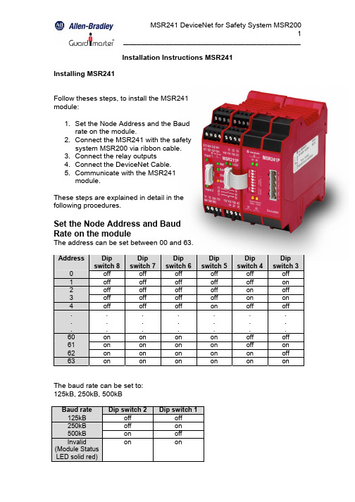
Installation Instructions MSR241 Installing MSR241Follow theses steps, to install the MSR241module:1. Set the Node Address and the Baudrate on the module.2. Connect the MSR241 with the safetysystem MSR200 via ribbon cable.3. Connect the relay outputs4. Connect the DeviceNet Cable.5. Communicate with the MSR241module.These steps are explained in detail in thefollowing procedures.Set the Node Address and BaudRate on the moduleThe address can be set between 00 and 63.Address Dipswitch 8Dipswitch 7Dipswitch 6Dipswitch 5Dipswitch 4Dipswitch 30 off off off off off off1 off off off off off on2 off off off off on off3 off off off off on on4 off off off on off off. . . ..................60 on on on on off off61 on on on on off on62 on on on on on off63 on on on on on on The baud rate can be set to:125kB, 250kB, 500kBBaud rate Dip switch 2 Dip switch 1125kB off off250kB off on500kB on offInvalid(Module StatusLED solid red)on onConnect the MSR241 with the safety system MSR200 via ribbon cableThe MSR241 mount to a panel or DIN rail, which must be grounded before installing the module.Connect the MSR241 either to the Basic module or to an output extension module on the right side of the MSR200 safety system via ribbon cable.The terminator for the EDM loop is integrated in the MSR241.Connect the relay outputsIf you want to use the relay outputs of the MSR241 connect them to your application.Connect the DeviceNet CableRefer to following information when connecting the DeviceNet wire to the MSR241.1. Connect the DeviceNet cable (drop line) to the unsealed DeviceNetterminal connector.2. Connect the terminal connector to the module. Use the side screws onthe terminal connector to fasten it to the module.IMPORTANTPin Number Wire Color Abbreviation Descriptionreturn1 Black V- Power2 Blue CAN_L Data line (CAN Low)3 Clear Shield Between cable jacket and wire4 White CAN_H Data line (CAN High)5 Red V+ Positive voltage (hot)The bus cable must be terminated with a resistor (121 Ω / +/- 1% / 0,25W). The resistor is contacted with CAN_H and CAN_L.Communicate with the MSR241 moduleTo transfer data from MSR241 to the D-Net it is required to upload the“E lectronic D ata S heet” (EDS file). This file is available for free download on the A-B web-page: /networks/eds/>Product NameMSR241PThe name of the EDS file is: 0001000C00A30100.edsThe MSR241 operates as a “Group 2 only slave” device and supports UCMM.The MSR241 is exchanged with the master through a polled, cyclic or change of state connection.Polled – Masters initiates communication by sending its polled I/O messages to the MSR241 module. The module consumes the message, updates any outputs, and produces a response. The response contains the input data.Cyclic – allows configuration of the module as an I/O client. The module will produce and consume its I/O cyclically at the rate configured.Change of state – production occurs when an input changes. If no input change occurs within the expected packet time, a heartbeat production occurs. This heartbeat production tells the scanner module that the MSR241 is alive and ready to communicate. Consumption occurs when data changes and the master produces new output data to the module.The module produces 4 bytes and consumes 1 byte for outputs.Byte DefinitionsThe table below shows the definition of the moduleConsumed output byteBit High Low00 K1 energized K1 de-energized01 K2 energized K2 de-energized02 Reserved Reserved03 Reserved Reserved04 Reserved Reserved05 Reserved Reserved06 Reserved Reserved07 Reserved Reserved Produced Input bytesInput byte 1: Configuration and status of MSR210 / MSR211Bit High Low00 Device ready Monitoring active01 Interrupt of any input All inputs valid02 Cross loop detected No cross loop03 Automatic reset Supervised reset04 Relay-output active (Safety system) Relay-output not active (Safety system)05 EDM dynamic EDM static06 EDM-loop open EDM-loop closed07 Internal fault or no basic moduleconnected No internal fault and basic module connectedInput-byte2: Status of Inputs of basic module and extension modules 1, 2 and 3 Bit High Low00 Basic module, input 1 interrupted Basic module, input 1 valid01 Basic module, input 2 interrupted Basic module, input 2 valid02 Extension module 1, input 1interrupted Extension module 1, input 1 valid (or module not existent)03 Extension module 1, input 2interrupted Extension module 1, input 2 valid (or module not existent)04 Extension module 2, input 1interrupted Extension module 2, input 1 valid (or module not existent)05 Extension module 2, input 2interrupted Extension module 2, input 2 valid (or module not existent)06 Extension module 3, input 1interrupted Extension module 3, input 1 valid (or module not existent)07 Extension module 3, input 2interrupted Extension module 3, input 2 valid (or module not existent)Input-byte3: Status of Inputs of Extension modules 4, 5, 6 and 7 Bit High Low00 Extension module 4, input 1interrupted Extension module 4, input 1 valid (or module not existent)01 Extension module 4, input 2interrupted Extension module 4, input 2 valid (or module not existent)02 Extension module 5, input 1interrupted Extension module 5, input 1 valid (or module not existent)03 Extension module 5, input 2interrupted Extension module 5, input 2 valid (or module not existent)04 Extension module 6, input 1interrupted Extension module 6, input 1 valid (or module not existent)05 Extension module 6, input 2interrupted Extension module 6, input 2 valid (or module not existent)06 Extension module 7, input 1interrupted Extension module 7, input 1 valid (or module not existent)07 Extension module 7, input 2interrupted Extension module 8, input 2 valid (or module not existent)Input-byte4: Status of Inputs of Extension modules 8, 9 and 10 Bit High Low00 Extension module 8, input 1interrupted Extension module 8, input 1 valid (or module not existent)01 Extension module 8, input 2interrupted Extension module 8, input 2 valid (or module not existent)02 Extension module 9, input 1interrupted Extension module 9, input 1 valid (or module not existent)03 Extension module 9, input 2interrupted Extension module 9, input 2 valid (or module not existent)04 Extension module 10, input 1interrupted Extension module 10, input 1 valid (or module not existent)05 Extension module 10, input 2interrupted Extension module 10, input 2 valid (or module not existent)06 Reserved Reserved07 Reserved ReservedImplemented DeviceNet ObjectsMandatory ObjectsObject Name ClassIdentify Object 01hMessage Router Object 02hDeviceNet Object 03hConnection Object 05hAcknowledge Handler Object 2BhDevice Configuration Object 64hIdentity Object, Class 01hClass Attributes (0)ID Name Service Description Value Type 1 Revision Get_Attribute_Single Objectrevision1 1 UINTInstance Attributes (1)ID Name Service Description Value Type 1 Vendor ID Get_Attribute_Single Identification of each vendor bynumber0001h UINT2 DeviceTypeGet_Attribute_Single Indication of general type of product 000Ch UINT3 ProductCode Get_Attribute_Single This is a code assigned by theVendor to describe the device00A3h UINT4 Revisions Get_Attribute_Single Revision of the item the IdentityObject represents 1.31 Arrayof:USINTUSINT5 Status Get_Attribute_Single Summary Status of the Devicebit0: Module Owed. A master hasallocate the modulebit1: reservedbit2: Configuredbit3 - 7: reservedbit8: Minor recoverable faultbit9: Minor recoverable faultbit10: Major recoverable faultbit11: Major recoverable faultbit12 - 15: reservedWORD6 SerialNumberGet_Attribute_Single Serial Number of the device UDINT7 Product-name Get_Attribute_Single Human readable identification “MSR241P” SHORT_STRINGMassage Router Object, Class 02hClass Attributes (0)ID Name Service Description Value Type 1 Revision Get_Attribute_Single Objectrevision1 1 UINTDeviceNet Object, Class 03hClass Attributes (0)ID Name Service Description ValueType 1 Revision Get_Attribute_Single Object revision 22UINTInstance Attributes (1)ID Name Service Description Def, Min, Max Type 1 MAC ID Get_Attribute_Single Currently used MacID Switches 0, 63 USINT 2 Baud rate Get_Attribute_Single Currently used baudrate0 = 125kB 1 = 250 kB 2 = 500kBSwitches, 0, 2USINT5 Allocation Informatio nGet_Attribute_Single Allocation Choice byteMaster´s MAC ID N/A Struct of:BYTE USINT 6 MAC ID SwitchChangedGet_Attribute_SingleThe Node Address Switches have changed since the last power-up / reset 0 = no change1 = Change since last reset or power-upBOOL 7 Baud RateSwitchChangedGet_Attribute_Single The Baud Rate Switches have changed since the last power-up / reset 0 = no change1 = Change since last reset or power-up BOOL 8 MAC ID SwitchValueGet_Attribute_SingleActual value of Node Address Switches Range: 0-63 USINT 9 Baud Rate Switch ValueGet_Attribute_Single Actual value of Baud Rate SwitchesRange: 0-3USINTAssembly Object, Class 04hInstance Attributes, Instance/Connection Point (64h)ID Name ServiceDescriptionValue Type 3 DataGet_Attribute_SingleData produced by MSR241 to the masterArray of byteInstance Attributes (96h)ID Name ServiceDescriptionDef, Min, Max Type3DataGet_Attribute_SingleData consumed by MSR241 from the masterArray of byteDeviceNet Connection Object, Class 05hClass Attributes (0)ID Name Service Description ValueType 1 Revision Get_Attribute_Single Object revision 11UINTExplicit Connection Instance (1, 2, 4 & 10…14)Instance 1 = Explicit messaging connection (Predefined in DeviceNet object) Instance 2 = Polled connection / COS / Cyclic consuming connection) Instance 4 = COS / Cyclic producing connectionInstance 10 - 14 = Explicit connection (UCMM allocated)ID Name Service Description Value Type1 StateGet_Attribute_Single Object State0: Non existent 1: Configuring2: Waiting for Connection ID 3: Established 4: Timed outUSINT2 Instance TypeGet_Attribute_Single Explicit messaging connection0 USINT 3 TransportClass TriggerGet_Attribute_Single Server / Transport Class 3 83h BYTE 4 Produced Cnxn IDGet_Attribute_Single CAN ID for transmissionUINT 5 Consumed Cnxn IDGet_Attribute_Single CAN ID for receptionUINT6 Initial Comm Characteri sticsGet_Attribute_Single The message group over which thecommunication occurs BYTE7 ProducedConnection SizeGet_Attribute_Single Maximum number of bytes transmitted across the connection 0100h UINT 8 ConsumedConnection SizeGet_Attribute_Single Maximum number of bytes received across the connection 0100h UINT 9 ExpectedPacketRateGet_Attribute_Single Set_Attribute_Single Timing associated with this connection (2500ms) 09C4h UINT C Watchdog Timeout Action Get_Attribute_Single Defines how to handle inactivity /watchdog timeouts 1: Auto delete3: Deferred delete1 USINTD Produced Connectio n Path LengthGet_Attribute_Single Number of bytes in theProduced_connection_path attribute 0 UINTE Produced Connectio n PathGet_Attribute_Single No connection pathEPATHF Consumed Connectio n Path LengthGet_Attribute_Single Number of bytes in the Consumedconnection path instance 0 UINT10 ConsumedConnectio n PathGet_Attribute_Single No connection path EPATHPolled I/O Connection Instance (2)ID Name Service Description Value Type1 StateGet_Attribute_Single Object State0: Non existent 1: Configuring2: Waiting for Connection ID 3: Established 4: Timed outUSINT2 Instance TypeGet_Attribute_Single I/O connection1 USINT 3 TransportClassTriggerGet_Attribute_Single Server/Transport Class 0 Server/Transport Class 0 80h 83h BYTE 4 Produced Cnxn IDGet_Attribute_Single CAN ID for transmissionUINT 5 Consumed Cnxn IDGet_Attribute_Single CAN ID for receptionUINT 6 Initial CommCharacteristicsGet_Attribute_SingleProduces over message group 1 Consumes over message group 2 Does not produce Consumes over message group 2 01h F1hBYTE7 ProducedConnection SizeGet_Attribute_Single Maximum number of bytes transmitted across the connection 4 UINT 8 Consumed Connectio n SizeGet_Attribute_Single Maximum number of bytes receivedacross the connection 1 UINT 9 ExpectedPacketRateGet_Attribute_Single Set_Attribute_Single Timing associated with this connection 0 UINT C WatchdogTimeoutActionGet_Attribute_Single Set_Attribute_Single 0: Transmission timeout 0 USINT D ProducedConnection Path LengthGet_Attribute_Single Number of bytes in the Produced_connection_path attribute 0007h (Polled)0000h (COS / Cyclic) UINTE ProducedConnection PathGet_Attribute_Single Application obj. producing data on this connection 20h, 04h, 25h, 64h, 00h, 30h, 03hEPATHF Consumed Connectio n Path LengthGet_Attribute_Single Number of bytes in theConsumed_connection_path attribute 7 UINT10 Consumed Connectio n Path Get_Attribute_Single Specifies the application object(s)that are to receive the data consumed by this connection object20h, 04h, 25h, 96h, 00h, 30h, 03hEPATH11 ProductionInhibitTimeGet_Attribute_Single Minimum time between new data production 0 UINTChange of state / Cyclic (4) (Acknowledged)ID Name Service Description Value Type1 StateGet_Attribute_Single Object State0: Non existent 1: Configuring2: Waiting for Connection ID 3: Established 4: Timed outUSINT2 Instance TypeGet_Attribute_Single I/O connection1USINT 3 TransportClass Trigger Get_Attribute_Single Defines behavior of the connection 00h = Cyclic03h = Cyclic + ACK 10h = COS13 = COS + ACK BYTE4 Produced Cnxn IDGet_Attribute_Single CAN ID for transmissionUINT 5 Consumed Cnxn IDGet_Attribute_Single CAN ID for receptionUINT 6 Initial Comm Characteri stics Get_Attribute_Single Produces over message group 1,Does not consume. Produces over message group 1, Consumes over message group 20Fh 01hBYTE7 ProducedConnection SizeGet_Attribute_Single Number of bytes transmitted across the connection 4 UINT 8 ConsumedConnectio n SizeGet_Attribute_Single Consumes o Byte on this connection 0UINT9 ExpectedPacketRateGet_Attribute_Single Set_Attribute_Single Timing associated with this connection 0 UINT C Watchdog Timeout ActionGet_Attribute_Single 0: Transmission timeoutUSINTD ProducedConnection Path LengthGet_Attribute_Single Number of bytes in the Produced connection path attribute 0007h UINTE Produced Connectio n PathGet_Attribute_Single Assembly Object, Instance 100,Attribute 3 is producing the data 20h, 04h, 25h, 64h, 00h, 30h, 03h EPATH F ConsumedConnection Path LengthGet_Attribute_Single Number of bytes in the Consumed connection path instance 0007h (no ACK) 0005h (ACK)UINT10 ConsumedConnection PathGet_Attribute_Single Acknowledge Handler Object, Instance 1 20h, 2Bh, 25h, 01h, 00hEPATH11 ProductionInhibitTimeGet_Attribute_Single Minimum time between new data production 0 UINTAcknowledge Handler Object, Class 2BhClass Attributes (0)ID Name Service Description ValueType 1 Revision Get_Attribute_Single Revision 11UINTInstance Attributes (1)ID Name Service Description Value Type1 Acknowled ge Timer Get_Attribute_Single Set_Attribute_Single Time (in ms) to wait for acknowledgebefore re-sending16 UINT 2 Retry Limit Get_Attribute_Single Set_Attribute_Single Number of ACK timeouts before retryreached event 1 USINT 3 ProducingConnection InstanceGet_Attribute_Single Connection instance, which contains the path of the producing I/O application object, which will be notified of ACK Handler events4 UINTDevice Configuration Object, Class 64hInstance Attributes (1)ID Name ServiceDescriptionDef, Min, Max Type 1 Number ofextension modulesGet_Attribute_Single Number of input extension modules of the safety system MSR2000, 0, 10BYTETroubleshoot with IndicatorsThe MSR241 has the following indicators:• Module status indicator• Network status indicator• Output status indicators K1 and K2Module Status IndicatorIndication StatusOff Device not poweredGreen DeviceoperationalFlashing green Device needs commissioning due to missing or incorrectconfiguration, MSR241 not connected to the Safetysystem MSR210Red UnrecoverablefaultFlashing red Minor fault recoverable, baud rate switches are invalid, MACID or Baud Rate switches are changed while on line or sincereset / power-upNetwork Status IndicatorIndication StatusOff Device not powered / Not onlineGreen Link OK, On line, ConnectedFlashing green On line, Not connectedRed Critical link failureFlashing red Connection timeoutOutput Status Indicator K1Indication Statusde-energizedOff K1Green K1energizedOutput Status Indicator K2Indication StatusOff K2de-energizedenergizedGreen K2SpecificationsOutput specification K1, K2Nominal switching capacity (resistiveload)2A 30V DCMax. switching power (resistive load) 60WMax. switching voltage 220V DCMax. switching current 2AMin. switching capacity 10µA 10mV DCUL/CSA rating 2A 30V DC0.3A 110V DC0.5A 125V DCGeneral SpecificationsIndicators Module Status red/greenNetwork Status red/greenOutput Status K1, K2 green Communication rate 125 kBaud, 250kBaud, 500 kBaud Max. length of fieldbus segment 100m … 500m (depends on baud rate /on the cable)IsolationOutput to DeviceNet Output to Output 500V ac/60s 500V ac/60sDeviceNet PowerVoltage Current 11 – 25V dc170mA maximumTemperature -5°C – 50°C Drg No: 57602/ Issue No: 0 Feb. 04。
- 1、下载文档前请自行甄别文档内容的完整性,平台不提供额外的编辑、内容补充、找答案等附加服务。
- 2、"仅部分预览"的文档,不可在线预览部分如存在完整性等问题,可反馈申请退款(可完整预览的文档不适用该条件!)。
- 3、如文档侵犯您的权益,请联系客服反馈,我们会尽快为您处理(人工客服工作时间:9:00-18:30)。
3. 将铁板从设备上取下
2. 设备与锁不共用电源
+
DC12V
+
DC电源
+
通电常开锁
FR 107
通电常闭锁
DC电源
4. 将铁板的螺丝孔位对准墙面上 钻好 的孔位,用螺丝将 胶垫和 铁板固定在墙上
5. 拧紧底部螺丝,将设备固定在 铁板上 (1)本设备可支持常开型和常闭型锁,只要分别连接在不同的端子上即可。对通电时打开,断电时 关闭的锁,应该使用NO1、COM1端子,对通电时关闭、断电时打开的锁,应该使用NC1、COM1端子。 (2)为了防止电锁在开关瞬间产生的自感电动势对门禁系统产生影响,在门禁系统现场应用 接线时,需要在电锁上并联一个型号FR107的二极管(请使用随机配备的FR107二极管, 请勿将其正负极接反)把电锁开关瞬间产生的自感电动势释放。
端子名称 GND RXD TXD PC机串口名称 Pin5-Gnd Pin3-Txd Pin2-Rxd
1)请先连接好其他连线后再连接电源线,如果发现机器不能正常运行,请先断掉电源总开关后再进行必 要检查;请注意:一切带电的接线都有可能会意外损坏机器,我们将不对此类操作导致的损害进行正 常的保修。 2)推荐使用DC 12V /3A的电源给设备供电。详情可咨询相关技术人员。 3)请首先阅读接线端子说明并严格按照规则进行接线,因错误操作而导致的设备损坏,均不属于保修范围。 4)所有接线端子的裸露部分不要超过5mm,以防过长的裸线意外接触,从而导致机器的损坏。 5)在静电比较严重的地方或者冬季,请先接地线,再连接其它线,以防止过大的瞬间静电损坏机器。 6)若电源与机器之间距离比较长,请勿使用网线或者其它类型的线代替,选择电源线时,应考虑传输距离 过长可能造成的电压衰减。 7)使用RS485组网时,请使用专业的485线和有源的RS232/485转换器,采用总线型布线。如果通讯距离 超过100米,需要在RS485总线的最后一台设备上并联一个终端匹配电阻,阻值约为120欧。
* 本公司保留最终更改权和解释权。
!
警告:请勿带电接线!
通电常闭锁
F18安装模板(仅供参考)
+
通电常开锁
设备与锁共用电源情况: : ULOCK=12V且I-ILOCK>1A……① 且锁与设备之间距离≤10米时。
FR 107
10
11
12
13
1. 将安装模板贴于将要安装设备的 墙面上,按照模板上的标示钻孔 (包括螺丝孔和引线孔)
2. 用螺丝刀将设备底部螺 丝取下
F18 安 装 指 南
版本:V1.2.2 日期:2015年1月
三、连接门锁
1. 设备与锁共用电源
+
一、安装设备
DC12V
布线孔
-
+12V GND BELLBELL+ SEN GND BUT NO1 COM1 NC1 NO2 COM2
+
ห้องสมุดไป่ตู้
DC12V
+
+12V GND BELLBELL+ SEN GND BUT NO1 COM1 NC1 NO2 COM2
1. RS232通讯方式
端子定义见右表:
2. RS485通讯方式
(1)与RS485读头之间的通讯 设备支持485读头功能,可以通过485连接SR200读头;同时可以作主从机,设备为主机, SR200读头为从机,支持485反潜功能。按 键选择"是"或"否"。"是"表示485读头功能 开启,此功能打开后,设备不能和电脑进行485通讯;选择"否"可以和电脑进行485通讯, 但485读头功能则关闭。
二、门禁系统示意图
门禁系统功能简介:
RS485 RS232/RS485转换器 ① ⑦ ④ 门磁 ② ⑥ TCP/IP ⑤
出门开关 BUT
① 当人员在设备上验证身份通过后,设备会输 出锁控信号,将锁开启。 ② 门磁将会自动检测门的开关状态,当门被意 外打开或门未关好时,将触发报警信号(开关 量信号)。 ③ 当门禁设备被非法拆卸,设备将会输出报警 信号。 ④ 可外接读头。 ⑤ 可外接出门开关,方便在室内将门打开。
+
-
+12V GND
!
警告:请勿带电接线!
六、Wiegand输出
到市场上大多数厂商的门禁控制器,此时本设备 只作为读头使用。
DATA0 DATA1 GND
七、Wiegand输入
RS485读头功能示意图(如右图)
(2)与PC之间的通讯
+12V GND DATA1 DATA0 RLED GLED BEEP
侧面图 背面图
(2) 设备与电脑通过交换机/集线器连接至网络。
PC机 交换机
IP地址:192.168.1.124 子网掩码:255.255.255.0 IP地址:192.168.1.201 子网掩码:255.255.255.0
…
复位按钮
防拆开关
十、注意事项 九、通讯设置
后台PC软件可通过3种通讯方式(RS232、RS485、TCP/IP)与设备通讯,进行数据交换,通过RS485、 TCP/IP还可以进行远程管理。
485+ 485 电源 + 电源黄色 紫色 红色 黑色
本设备具有标准的Wiegand26输出接口,可以连接 本设备具有Wiegand信号输入接口,能外接读头, 读头与本设备可分别安装在室内外,共同控制门 锁,控制进出。
WD0 WD1 GND RXD TXD 门禁控制器 GND 485+ 485+12V GND IWD1 IWD0 RLED GLED BEEP
+
+
-
+
-
FR 107
+12V GND BELLBELL+ SEN GND BUT NO1 COM1 NC1 NO2 COM2
设备与锁不共用电源情况: 1)ULOCK=12V 且 I-ILOCK≤1A; 2)ULOCK≠12V; 3)锁与设备之间距离>10 米时。
+
五、连接电源
本设备的工作电源为DC12V,工作电流为500mA, 待机电流为50mA,将电源的正负级直接连接在 +12V和GND之间即可(请勿将正负极接反)。
四、连接其他装置
门铃
%
出门开关 BUT
门锁
出门开关
出门开关 报警器电源
%
门铃 外接读头
+
BELLBELL+ SEN GND BUT NO1 COM1 NC1 NO2 COM2
门磁
DC12V
报警器
③ 报警器
⑥ 可外接门铃。 ⑦ 可通过RS485、TCP/IP与PC机联网,通过门禁 管理软件轻松管理多台终端设备。
本设备只能连接输出不超过DC12V的报警器。 ①:I定义为设备电源输出的电流,ULOCK定义为锁的工作电压,ILOCK定义为锁的工作电流。
* 本公司保留最终更改权和解释权。
+
-
-
-
+
+12V GND BELLBELL+ SEN GND BUT NO1 COM1 NC1 NO2 COM2
+
DC12V
FR 107
3. TCP/IP通讯方式
端子定义见右表: 两种连接方式如下: (1) 设备与电脑通过交叉网线直接连接。
端子名称 RJ45-1 RJ45-2 RJ45-3 RJ45-6
线序 TX+ TXRX+ RX-
颜色 白橙 橙 白绿 绿
八、其他功能
1. 复位功能: 由于误操作或其它意外故障导致设备无法正常工作时,可使用 此复位按钮将设备重新启动。 操作:使用直径小于2mm的顶部尖锐的工具顶入此孔一下 2. 防拆开关: 当机器被拆除时,将发出报警信号触发报警器报警。
门禁机
读头
使用RS485组网时,请使用专用的485线和有源的485 转换器,采用总线型布线,见右图。 端子定义:
端子名称 485+ 485PC机串口名称 RS485通讯+ RS485通讯RS485转换器 RS485总线 485+ 485485+ 485485+ 485485+ 485-
1. 设备到门禁控制器或读卡器的距离建议不超过90米(如需传输距离更长或使用环境中有干扰时, 请使用Wiegand信号延长器)。 2. 不论设备是否与门禁控制器或读卡器共用电源,都必须确保设备与门禁控制器或读卡器共地,以 保证Wiegand信号稳定。
