SD卡 DMX解码说明书(6通道
DMX512中文使用说明书
DMX512中文使用说明书一、四位数码管说明:XXXX*第一位代表CHASE,共有6个*第二位代表SCENSE,共有8个*第三四位代表BANK,共有30个*设置MIDI通道时第三四位代表MIDI通道,共有16个MIDI通道*一个CHASE最多可以包含240个SCENSE*一个BANK最多可以包含8个SCENSE*一个SCENSE最多可以包含192个通道(也可以说是12个SCANNER) SCANNER1:通道1~通道16SCANNER2:通道17~通道32以此类推SCANNER12:通道181~通道192*一个SCANNER最多可以包含16个通道*调节滑杆时显示数值或者百分比二、操作时请注意数码屏的指示灯在什么状态。
*BLANKOUT*STEP*PROGRAM*MUSIC TIGGER*AUTO TIGGER三、DMX512面板功能说明1、SCANNERS按下SCANNER键,其旁边的LED灯亮,其中连接8个通道的输出可被调节,在SCENS运行时,如果可调电位器控制为OFF,则调节电位器不会影响通道输出,但如果可调电位器控制为ON,则通道输出会随相应的可调电位器的改变而改变;2、SCENS按健按下一个SCENS键可触发SCENS或存入一个SCENS,第二个数码管头显示SCENS1-8;3、可调电位器调节可调电位器改变DMX的通道输出大小,最小是0最大为255或者从0%-100%,可调电位器1-8控制连续的八个通道;4、PAGE/SELECT键选择PAGE A或PAGE B,PAGE A为每个SCANNER的前八个通道PAGE B为每个SCANNER 的后八个通道;5、SPEED SLIDER推动这个推杆调整走灯速度;6、FADE TIME SLIDER推动这个推杆调整FADE TIME;7、LED DISPLAY8、BANK按键(↑/↓)第三位和第四位数码管显示BANKS(01-30),按下↑/↓键,BANK增大或减小,显示的SCENS 为该BANK里的SCENS;9、CHASE 1-CHASE 6键用于CHASES编程或CHASES运行的选择;10、PROGRAM键上电本机在走动运行状态,按下PROGRAM键盘2秒,编程指示灯闪动可编程SCENSR和CHASER,再按下PROGRAM键2秒,编程指示灯灭回到运行状态;11、MIDI/ADD键A、在运行状态按住MIDI键2秒,第3及第4位数码管闪动,通过↑或↓选择MIDI通道,再按MIDI键2秒结束MIDI通道的设置选择的MIDI通道被存贮;或者除↑/↓键以外的任何键都可结束MIDI通道的设置,不存贮所选取的MIDI通道;B、在编程状态,用于编辑;12、AUTO/DEL键A、在运行状态,按下AUTO/DEL键,自动触发指示灯亮,表示在自动触发状态,再按下AUTO 键退出自动触发状态,自动触发指示灯灭;B、在编程状态,用于SCENS及CHASE编程;13、MUSIC/BANK COPY键A、在运行状态,按下MUSIC键,声音触发指示灯亮,可由声音触发SCENS,再按一下MUSIC 键,声音触发指示灯灭,退出声音触发状态;B、在编程状态,用于SCENS及CHASE编程;14、TAPSYNC/DISPLAY键A:(1)、在AUTO运行状态,最后两次按下TAP SYNC/DISPLAY键决定SCENS运行的速率,最大时间为十分钟;(2)、不在AUTO运行状态,转换00-255或0%-100%;B:在编程状态(1)、对CHASE编程时,在步数显示和BANK显示之间转换;(2)、不在CHASE编程时转换00-255或0%-100%。
DMX控制灯光设备手册说明书
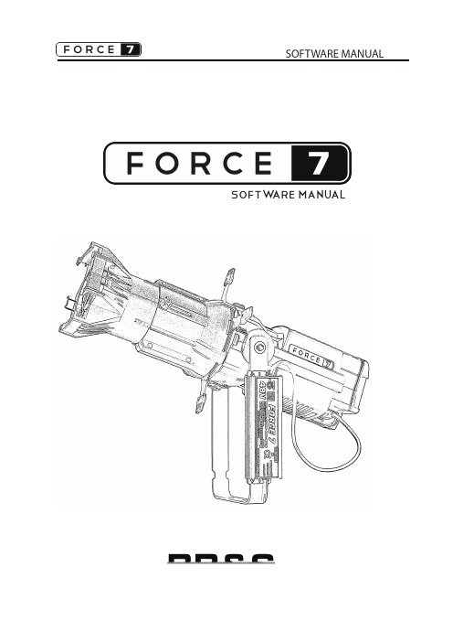
SOFTW ARE MANUAL1DMX present indicator8 bit Indicator Note: Beware, when using Strobe Lenght, that if the Strobe Lenght is egual to or longer than the ash and interval between ashes, the unit will not strobe.If maximum strobe length is used the fastest strobe possible will be aprox. 17 ( 7% )Strobe on IndicatorLinear curve on IndicatorOpen menu / Go back Select / Con rm Scrolling UP / Increase value Scrolling DOWN / Decrease valueMENU ENTER UP DOWN DMX ChannelsMode Channel Parameter Value Percent Function8 Bit 1 Dimmer 0 - 255 0 - 100 Coarse dimming8 Bit 1 Dimmer 0 - 255 0 - 100 Coarse Dimming w. Strobe 2 Strobe 0 - 5 0 O pen mode 6 - 125 1 - 49 Slow to Fast Strobe 126 - 130 50 O pen 131 - 250 51 - 99 Slow to Fast Random 251 - 255 100 O pen 3 Strobe 0 0 - 100 Short to Long Flash length16 Bit 1 Dimmer 0 - 255 0 - 100 Coarse dimming 2 Dimmer 0 - 255 0 - 100 Fine dimming16 Bit 1 Dimmer 0 - 255 0 - 100 Coarse dimming w. Strobe 2 Dimmer 0 - 255 0 - 100 Fine dimming 3 Strobe 0 - 5 0 O pen mode 6 - 125 1 - 49 Slow to Fast Strobe 126 - 130 50 O pen 131 - 250 51 - 99 Slow to Fast Random 251 - 255 100 O pen 4 Strobe 0 0 - 100 Short to Long Flash length2SOFTWARE MENUDefault values indicated by bold fontAddr 1 DMX adress value 1 - 512M ode Resolution 8 bit resolution 16 bit resolution Response Slow (fade between values) Fast (snap between values) Curve Square dimmer curve Linear dimmer curve Strobe OFF On - (adds 2 strobe channels) Fan HIGH - No fan speed limit LOW - Fan speed limited (Silent) noDMX Action when loss of DMX signal: HOLD - last received DMX value OFF - Sets output to zero MAN - Go to Manual DMX value Display OFF 2n - Display o after 2 minutesO N - Display always on Tools Ver Shows software version HW Ver Shows hardware version L Temp LED temperature DMX In 3 rst digits shows DMX adress 3 last digits shows DMX value Reset Con rm (Reset unit by pressing enter) test Fan Fan test First 2 digits - set fan speed level 0 - 31 Last 3 digits - RPS (rounds per second) test displayDisplay test - cycles through all segments of the display Log Log C° Minimum and maximum logged temperature in °C UP and DOWN scrolls min. and max. on time PSU on time in hours on LED LED on time in hours on Cnt Counts number of times unit has been switched onSerial Internal serial number used as service number PSU U PSU voltage in Volts DMX HZ DMX refresh rate DMX CH No. of DMX ch. transmitted by controllerDMX br Break lenght of DMX in microseconds Manual 0 Manual intensity 0 - 100% Intensity saved when pressing ENTER (Display is always on in manual mode)POWER UPAfter power ON, the unit will be operational after 10 seconds.During the power up the unit will do selftests, including fan test.SPECIAL FUNCTIONSWithin the rst 10 seconds PRESS and HOLD.......ENTER till the display reads “MAN 00” to reset stored manual value to zero....MENU till the display reads “RESET” to reset all modes and adress settings to default....DOWN till the menua reads “INTRO” to show the units Software Version.DISPLAY ORIENTATIONTo ip orientation o display press UP and DOWN simultaneously.MODE FEATURES EXPLAINED (Default settings in bold)Resolution: 8 bit: Less DMX channels used.16 bit: Smoother fades.Response: Slow:Fades between values. Smoother fades.Fast: Snaps between values. Fast operation.Curve: Square: Dimmer curve designed for LEDsLinear: Standard dimmer curveStrobe: OFF: Less DMX channels used.ON: Strobe function added.Fan: HIGH: More cooling with no fan speed limitLOW: Silent operation - Fan speed limitednoDMX: HOLD:If DMX signal is lost, the unit will maintain the last value received.OFF: If DMX signal is lost, the unit will go to 0% light level.MAN: If DMX signal is lost, the unit will go to the saved manual light levelDisplay: OFF 2n:The display will switch o after 2 minutes of idle operation.ON: The display will always be on.HEAT PROTECTIONDimmed state: If the PCB temperature reaches 55° the LEDs starts to dim the light to cool o .O state: If the PCB temperature reaches 63° the LED turns o .in either state the display will read L HEATFan starts cooling when the LED reaches 50°. It starts slowly and increases in speed if thetemperature keeps rising.Error MessagesL HEAT LED is too hotWhat to do: 1. Make sure air vents are not blocked.2. Respect the max. ambient temperature.3. Clean out any dust in the unit4. Let it cool downSEN ER LED heat chip encounters communication errorsWhat to do: Contact quali ed service technicianFAN ER Fan is experiencing problems.What to do: 1. Try to determine if anything is blocking the fan or ventsunit2.Reset3. Contact quali ed service technicianLV XXX Internal voltage too low - XXX is the measured internal voltage3What to do: Contact quali ed service technicianFAQ - TROUBLESHOOTINGAt upstart the display keeps 1. Software upload has been interrupted.changing between bl_x_xx and 4551 Upload new software.The luminaire does not respond to DMX 1. Check - that the cable is properly connected to DMX IN2. Check - that the DMX present indicator is on.3. Check - “DMX IN” in the menu to see if the luminaire receivesany DMX data.The luminaire is ashing 1. Check your strobe settings vs. your patchVERSION CHANGESSW Changes:Optimized software delay on keys to prevent “double clicking”New Functions:Added a serial number as a service number. Not the actual xture serial number.Added warning if supply voltage is out of range, for advanced troubleshooting.Added menu Power On Count, counts number of times xture has been turned on.Bugs:Updated the timer, Fixture On Cnt and LED On Cnt, to increase counter stabilityTemperature warning when at minus temperatures changed to only show the temperature.4。
解码器说明书

解码器使用说明书(中文版)注意事项:1.安装场所远离高温的热源和环境,避免阳光直接照射。
为确保本机的正常散热,应避开通风不良的场所。
本机应水平安装,为了防止电击和失火,请勿将本机放置于易燃、易爆的场所。
小心轻放本机避免强烈碰撞、振动等,避免安装在会剧烈震动的场所。
避免在过冷、过热的场所间相互搬动本机,以免机器内部产生结露,影响机器的使用寿命。
2.避免电击和失火使用说明书切记勿用湿手触摸电源开关和本机。
勿将液体溅落在本机上,以免造成机器内部短路或失火。
(中文版第二版)勿将其它设备直接放置于本机上部。
当本机的电源线与电源插座连接后,即使未启动本机,机器内部仍有电压。
安装过程中进行接线或改线时,都应将电源断开,预防触电。
接通本机电源后,露在外面的接线端子有危险电压,切记勿触碰。
重要提示:为了避免损坏,请勿自动拆开机壳,必须委托有资格有专业维修人员在指定的维修单位进行维修。
清洁装置时,请勿使用强力清洗剂,当有灰尘时用干布擦拭装置。
不得在电源电压过高和过低的场合下使用该本机。
务请通读本使用说明书,以便您掌握如何正确使用本机。
当您读本说明书后,请把它妥善保存好,以备日后参考。
如果需要维修,请在当地与经本公司授权的维修站联系。
环境防护:本机符合国家电磁辐射标准,对人体无电磁辐射伤害。
Copyright 2000-2005. All Rights Reserved.智能解码控制器产品的发行和销售由原始购买者在许可协议条款下使用;未经允许,任何单位和个人不得将该产品全部或部分复制、再生或翻译成其它机器可读形式的电子媒介; PTZ Intelligent Controller1. 设备概述智能型解码器是与安防监控系统设备配套使用的一种前端控制设备,可控制室内外云台、电动变焦镜头、摄像机、灯光和雨刷。
控制方式为RS-485,兼容多种控制协议。
智能型解码器具有超强抗死机性能,镜头电机保护、自动匹配控制协议的功能,还具有直流12V 输出、交流24V 输出。
解码器使用说明书(单页版本)

23
35
36
46
56
37
47
57
38
48
58
39
49
59
40
50
60
41
51
61
42
52
62
43
53
63
44
54
64
45
55
地址计算方法:(以下是开关状态在OFF时的值)
开关:1 2 3 4 5 6 7 8
对应的值:1 2 4 8 16 32 64 128
地址号等于开关所对应的值相加。
3.连接示意图:
COM:对应镜头的公共端COMMON
O/C:对应镜头的光圈调节
N/F:对应镜头的焦距调节
W/T:对应镜头的变焦调节
若依此连接,控制位置不对,可自行调整之。
常见故障排除:
以下所列故障主要是针对解码器而言,有关系统主机及云台镜头的故障在此不再作讨论。
指示灯不亮,解码器不动作
可能原因:
无电源;
LED开关未短接
地址设置:
在同一系统中,每一个解码器都必需有一个唯一的地址码供系统识别。您应将解码器的地址设定成与摄像机号码一致。例如:第八台摄像机有云台、镜头,安装有解码器,那么,您应将解码器的地址设定成八。
有些系统地址是从0开始的,如天地伟业、天大天财矩阵系统和IDRS数字硬盘录像系统等,若遇此情况,请将解码器的地址设置成从0开始即可。即第一台摄像机所接的解码器地址设为0,其他依此例推。
解码器采用RS232通讯方式,B为信号端,G(GND)为屏蔽地,且B与COM口的第三脚相接,GND与COM的公共地相接。(R232通讯方式只适宜短距离通讯)
NTX-T600使用手册_V1.07.5557
1.3
使用环境 ............................................................................................................................ 2
1.4
通信协议 ............................................................................................................................ 2
NTX
Converged Communications PBX
4 线路智能 IP 话机
使用手册
NTX-T600 使用手册 V1.07
目录
1.
NTX-T600 特性.................................................................................................................... 1
管理员密码 ...................................................................................................................... 13 恢复出厂值 ...................................................................................................................... 14 基本设置 .......................................................................................................................... 14 状态设置 .......................................................................................................................... 15 离位转移 .......................................................................................................................... 15 振铃音 .............................................................................................................................. 16 可编程键 .......................................................................................................................... 17 热线设置 .......................................................................................................................... 19 显示控制 .......................................................................................................................... 19 语言选择 .......................................................................................................................... 20 一键会议管理................................................................................................................... 20 自动上传下载配置........................................................................................................... 21 NTX-IPA配置话机............................................................................................................. 22 上传铃声 .......................................................................................................................... 22 配置一键会议组............................................................................................................... 23 设置可编程键................................................................................................................... 23 系统版本 .......................................................................................................................... 24 重启 .................................................................................................................................. 24 其它功能和设置............................................................................................................... 25 通讯录 .............................................................................................................................. 25 通话记录 .......................................................................................................................... 25 邮箱和消息功能............................................................................................................... 26 音量设置 .......................................................................................................................... 27
PX0408 DMX512 RDM RGBW 解码器使用说明书

PX0408DMX512/RDM RGBW DecoderSummary·Meets DMX512/1990,RDM /2009 protocol ·Supported RDM parameters:DISC_UNIQUE_BRANCH DISC_MUTE DISC_UN_MUTE DEVICE_INFOSOFTWARE_VERSION_LABEL DMX512/RDM_START_ADDRESS IDENTIFY_DEVICE MANUFACTURER_LABEL SUPPORTED_PARAMETERSIn DMX mode set the DMX address manually by switch; in RDM mode, the host computer address allocationProduct FeaturesTechnical Parameter 1. The product has 4 channels output. The maximum 8A current per channel and the total power up to 768W.2. Set the address with the dial switch, and the operation is simple and quick.3. Euro terminal blocks and RJ45 two DMX interfaces are provided to improve signal transmission efficiency and anti-interference capability.4. With the RDM remote management protocol, the RDM master can browse and set the parameters, the DMX address modification, the device identifica-tion and other operations through the RDM master control.5. It has the functions of short-circuit, over-temperature, overload automatic protection and recovery.6. Fast self-test function.Product model:Input signal:DMX interface:Input voltage:Output:Output power: Working temperature:product size :packing measurement :Weight (net weight):Dimension(mm)Short Circuit Welcome to the PX series DMX512/ RDM decoding drive. The PX series adopts advanced microcomputer control technology, and converts the widely adopted DMX-512/1990 and RDM/2009 standard digital control signals into analog control signals. 1-4 output channels can be selected, and 256-level control levels can be implemented for each channel. The invention can be used for the connection of the computer digital output light-adjusting table and the analog silicon box, and the use occa sions of the control of the LED lamp for the building and the lamp decoration.PX0408DMX512/ RDM RJ45, green terminal 12-24VDC 8 A *4 CH.384W (12V)MAX / 768W (24V)MAXOFF ON1248163264128256FUNOFFONOFFONOFFONDIP Switch Setting···DMXRDM DMXRGBW LEDMAXDIP1~9: sets the address of the first channel of DMX decoder, and the corresponding table of dialing switch shows that the sum of numbers is the first channel address of DMX decoder. The valid address in DMX mode is 1 ≤ 511, (address 511 is self-test mode, output RGBW gradient). When the address is set to 0, the default is RDM mode.DIP10:FUN represents the end resistance of 120 ohms.(1) RJ45 Signal input and output interfaces(2)Signal light(The normal signal indicator is green flashing, but if the signal is abnormal, the indicator light is not on.)(3)Euro terminal blocks (4)Address setting interface (5)Power input interface (6)Output interface DIP1000000000DIP2DIP3DIP4DIP5DIP6DIP7DIP8DIP9DIP10NA·····Interface DescriptionConnection diagramSystem connection diagramThe Setting Of The Dmx First Address:RDM mode:when the code extraction switch 110 is fully turned upward.DMX mode: FUN = OFF (when the 10th pull-out switch is up), The DMX address can now be set by the 1-9 dial switchSelf-test mode: FUN = OFF (address 511 is self-test mode, output RGBW gradienHookup(1)The DMX512/ RDM is directly connected, and the DMX512/ RDM signal has positive and negative signals. Pay attention to the polarity when wiring. A positive signal, a negative signal, and a ground signal are connected to an interface corresponding to the device(2)Refer to "DMX series address dial code table" to set DMX address by dial code switch.(3) The tail of the whole wiring needs to be connected to the signal Terminator at the end of the connection.PX0408概述产品尺寸(mm)·符合DMX512/1990,RDM/2009国际标准协议·支持RDM 参数:DISC_UNIQUE_BRANCH DISC_MUTE DISC_UN_MUTE DEVICE_INFOSOFTWARE_VERSION_LABEL DMX512/RDM_START_ADDRESS IDENTIFY_DEVICE MANUFACTURER_LABEL SUPPORTED_PARAMETERS在DMX 模式下通过拨码开关手动设置DMX 地址; 在RDM 模式下,上位机分配地址产品特点技术参数欢迎使用PX 系列DMX512/RDM 解码驱动器。
DMX Emergency Bypass Controller 产品说明书
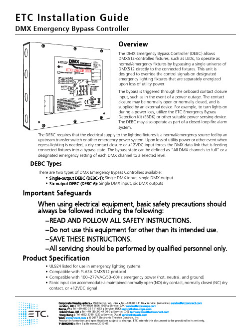
Corporate Headquarters ⏹ Middleton, WI, USA ⏹ Tel +608 831 4116 ⏹ Service: (Americas) **********************London, UK ⏹ Tel +44 (0)20 8896 1000 ⏹ Service: (UK) *********************Rome, IT ⏹ Tel +39 (06) 32 111 683 ⏹ Service: (UK) *********************Holzkirchen, DE ⏹ Tel +49 (80 24) 47 00-0 ⏹ Service: (DE) ****************************Hong Kong ⏹ Tel +852 2799 1220 ⏹ Service: (Asia) *******************OverviewThe DMX Emergency Bypass Controller (DEBC) allows DMX512-controlled fixtures, such as LEDs, to operate as normal/emergency fixtures by bypassing a single universe of DMX512 directly to the connected fixtures. This unit is designed to override the control signals on designated emergency lighting fixtures that are separately energized upon loss of utility power.The bypass is triggered through the onboard contact closure input, such as in the event of a power outage. The contact closure may be normally open or normally closed, and is supplied by an external device. For example, to turn lights on during a power loss, utilize the ETC Emergency BypassDetection Kit (EBDK) or other suitable power sensing device. The DEBC may also operate as part of a closed-loop fire alarm system.The DEBC requires that the electrical supply to the lighting fixtures is a normal/emergency source fed by an upstream transfer switch or other emergency power system. Upon loss of utility power or other event when egress lighting is needed, a dry contact closure or +12VDC input forces the DMX data link that is feeding connected fixtures into a bypass state. The bypass state can be defined as “All DMX channels to full” or a designated emergency setting of each DMX channel to a selected level.DEBC TypesThere are two types of DMX Emergency Bypass Controllers available:•Single-output DEBC (DEBC-1): Single DMX input, single DMX output •Six-output DEBC (DEBC-6): Single DMX input, six DMX outputsImportant SafeguardsWhen using electrical equipment, basic safety precautions should always be followed including the following:–READ AND FOLLOW ALL SAFETY INSTRUCTIONS.–Do not use this equipment for other than its intended use.–SAVE THESE INSTRUCTIONS.–All servicing should be performed by qualified personnel only.Product Specification•UL924 listed for use in emergency lighting systems •Compatible with PLASA DMX512 protocol•Compatible with 100–277VAC/50–60Hz emergency power (hot, neutral, and ground)•Panic input can accommodate a maintained normally open (NO) dry contact, normally closed (NC) drycontact, or +12VDC signalInstallationInstall the DEBC enclosure on a suitable surface, within 1,640 ft (500m) of the Emergency Bypass Detection Kit (EBDK) or other suitable power sensing or triggering device providing a contact closure output.Required Installation Tools and Supplies•Small 3mm or 1/8” flat-blade screwdriver (jeweler’s screwdriver) for wire terminations •#2 Phillips screwdriver for the front cover•Four mounting bolts or screws suitable to hold up to 6lb (2.7kg)Install the DEBC1:Remove the front cover from the DMX Emergency Bypass Controller, revealing access to the mounting keyholes.a:Remove the six screws securing the front cover to the unit.b:Lift the cover from the unit.2:Use the measurements provided in the image that follows for mounting bolt locations.3:Secure the DEBC enclosure to the wall using four bolts (mounting hardware not provided).Remove these screws to removecoverRemove these screws to removecover4:To further secure the box to the wall, use a single screw (also not provided) in either bottom slot (see image below).Route Conduit and WiringFour conduit knockouts are provided on each side of the enclosure for installation convenience. Emergency or normal/emergency AC power will utilize the two topmost knockouts while the remaining knockouts near the bottom of each side will accommodate the Class 2 wiring (DMX and panic input wire).Note:Install the DEBC enclosure on a suitable surface, within 1,640ft (500m) of theEmergency Bypass Detection Kit (EBDK) or suitable triggering device.Termination typeSpecified wire typeAC input (emergency or normal/emergency) 2 wires (hot, neutral)24–10AWG / .2mm 2–4mm 2Ground Ground lug accepts 14–2AWG / 2.5mm 2–35mm 2Panic input 30–12AWG / .05mm 2–2.5mm 2DMX in/outBelden 9729 (or approved equivalent for DMX, such as CAT5 or CAT5E with insulation displacement connectors)Note:Power and control wires must be run in separate conduits. Follow all local coderestrictions.Connect Panic InputThe panic input can be configured as a maintained dry contact or a +12VDC signal. Determine which configuration is best for your application and wire the receptacle on J4 of the control board accordingly.Maintained Dry Contact1:Strip 1/4” (6mm) insulation from the two panic wires.2:Locate and remove the PANIC IN connector from J4 on the control board.3:Loosen the V OUT terminal and the INPUT terminal.4:Insert the first panic input wire into the V OUT terminal. Using the jeweler’s screwdriver, tighten the screw firmly onto the wire.5:Insert the second panic input wire into the INPUT terminal. Using the jeweler’s screwdriver, tighten the screw firmly onto the wire.+12VDC Signal1:Strip 1/4” (6mm) insulation from the two panic wires.2:Locate and remove the PANIC IN connector from J4 on the control board.3:Loosen the INPUT terminal and the COM terminal.4:Insert the +12VDC wire into the INPUT terminal. Using the jeweler’s screwdriver, tighten the screw firmly onto the wire.5:Insert the common wire into the COM terminal. Using the jeweler’s screwdriver, tighten the screw firmly onto the wire.Note:The V OUT terminal can also be identified by the triangle that points to pin 1.Note:Identify the panic wires coming from the sensing device and determine which one is+12VDC and which one is common.CONFIG 1234RECORDPANIC INV OUT INPUT COMONOFFConnect DMX In/Out1:Locate the DMX cable that is coming “in” from the DMX source: this is DMX IN. Label the cable.2:Locate the DMX cable (or cables) going “out” to the DMX controlled fixtures, and label the cables. 3:Prepare and terminate each of the cables to the appropriate connectors for the cable type:•Belden 9729 cable (or equivalent) and screw terminal style connectors: Follow the cablepreparation instructions as provided with the DMX Cable Preparation Kit with Screw Connector for Belden 9729 cable (part number 4100A1012).•Category 5 cable (Belden 1583A or equivalent) and insulation displacement (IDC) connectors: Follow cable preparationinstructions as provided with the DMX Cable Preparation Kit for Category 5 cable (part number 4100A1013).4:Install the connectors to the appropriate receptacles on the control board. DMX IN installs to J8, and the other connections are as follows:•Single-output DEBC: DMX OUT/THRU to J9 (see image at right)•Six-output DEBC: DMX OUT/THRU to J9, and DMX OUT to J10, J11, J5, J6, and J7 (see image below)Note: A DMX Cable Preparation Kit with Screw Connector (part number 4100A1012) for usewith Belden 9729 cable (or equivalent) is provided with the DMX Emergency Bypass Controller. Before you connect the DMX IN and DMX OUT, please follow the instructions in that kit to prepare the cable.ETC offers a DMX Cable Preparation Kit with IDC Connector (part number 4100A1013) for use with installations utilizing Category 5 cable (or equivalent, such as 5e or 6). Contact ETC Professional Services to order this cable preparation kit, if required.Note:The six-output DMX Emergency Bypass Controller has one DMX OUT/THRU output (J9)and five optically isolated DMX outputs. RDM is passed through the device to the DMX OUT/THRU connection only; the other outputs transmit DMX but do not provide RDM functionality.When the DMX Emergency Bypass Controller is unpowered, DMX data will pass to the DMX OUT/THRU output only.D M X I ND M X O U T /T H R USingle-output DMX connectionsD MXI ND MXO U T/T HRUDM XO UT1D MXOU T 2D M X O U T 3D M X O U T 4D M X O U T 5Six-output DMX connectionsConnect AC and Ground Input1:Strip 1/2” (13mm) of insulation from the hot, neutral, and ground wires.2:Locate and loosen the earth ground lug located on the right side of the control board, near the AC INPUT connector.3:Locate the earth ground wire (typically green or green with a yellow stripe) and insert it into the ground lug; tighten the lug firmly onto the wire.4:Locate the two-pin connector located at J1 on the control board; using the jeweler’s screwdriver, loosen both terminals.5:Locate the hot wire (typically black) and insert it into pin 1, labeled “L” on the AC INPUT terminal; tighten the terminal firmly onto the wire.6:Locate the neutral wire (typically white) and insert it into pin 2, labeled “N” on the AC INPUT terminal; tighten the terminal firmly onto the wire.WARNING:Risk of electric shock! Before terminating the AC power wiring, verify that themain breaker is in the off position and follow the proper lockout/tagout procedures per NFPA Standard 70E.Note:In order for the system to function correctly in an emergency state, the DMX EmergencyBypass Controller must be powered via a normal/emergency supply provided by an upstream transfer device such as the ETC SC1008 BCELTS or ELTS2. If the DMXEmergency Bypass Controller is powered from an emergency supply only, DMX will be available only on the DMX OUT/THRU connector when power is absent.AC INPUTLN Ground LugConfigureSet the configuration for the DMX bypass operation at the CONFIG DIP switches, located at S1 on the control board. By default, all four DIP switches are in the OFF position. See the table below to set the function of the DMX bypass.Power Up1:Verify that incoming power to connected normal/emergency lighting fixtures is wired to an emergency lighting transfer device, such as the ETC SC1008 Branch Circuit Emergency Lighting Transfer Switch (BCELTS) or Emergency Lighting Transfer System (ELTS2).2:Replace the cover on the DMX Emergency Bypass Controller. Be careful not to damage the Test button and the Normal/Bypass indicator while replacing the cover.3:Restore power to the main breaker that supplies power to the controller. See Operational Notes and Testing for details of how the DMX Emergency Bypass Controller should respond when powered.Switch 1: ModeSwitch 2: Panic InputOFF Panic look sets all 512 channels to full Normally Open (NO) maintained panic input ONPanic look is recordable (snapshot)Normally Closed (NC) maintained panic inputSwitch 3Switch 4Panic Exit DelayOFF OFF Deactivates panic look immediately when panic input is released.OFF ON Deactivates panic look 10 seconds after panic input is released.ON OFF Deactivates panic look 30 seconds after panic input is released.ON ONDeactivates panic look 10 minutes after panic input is released.WARNING:Replace the cover on the DEBC before applying power to avoid electric shock!CONFIG 1234RECORDPANIC INV OUT INPUT COMONOFFOperational Notes and TestingVerify that the external power sensing or triggering device is working properly. This could be the ETC Emergency Bypass Detection kit (EBDK) or a fire alarm system.What to Expect in Normal DMX ModeIf the DMX Emergency Bypass Controller is powered from a normal/emergency power source, the DEBC’s Normal/Bypass LED indicator (located on the front of the unit) will illuminate green.What to Expect in DMX Bypass Mode (loss of normal power)•The DEBC Normal/Bypass LED indicator will illuminate red when an emergency state (panic input) is triggered.•The DMX panic look that was preset using the CONFIG DIP switches will output to the lighting fixtures attached to the DEBC.Recording a Panic Look from an External DMX512 Source1:Set the CONFIG DIP switch 1 in the ON (up) position.2:Verify that the external DMX source is outputting DMX to the normal/emergency lighting fixtures through the DEBC.3:Hold down the RECORD button, located at S2 on the control board, for approximately 5seconds.The Status LED, located below the RECORD button, will flash rapidly while you hold the RECORD button, and then will illuminate solid on when recording is complete (if DMX is received by the DEBC).Periodic Testing ProcedurePressing and holding the Test button (located on the front panel of the DEBC) forces the unit to output its panic look. This is true as long as it is receiving power, regardless of the PANIC IN closure/signal state. Once you release the Test button, the DEBC will stop bypassing incoming DMX and return to the normal state after two seconds.The Panic Exit Delay timer settings (set using DIP switches 3 and 4) have no effect on the DEBC when you release the Test button. See Configure on page 7.Note:If the DMX source is unplugged or DMX is interrupted from the DEBC during recording,the Status LED will instead turn off at the end of recording. This indicates that the panic look was not recorded.CONFIG 1234RECORDPANIC INV OUT INPUT COMONOFF。
PULSE DMC-6 6 Channel DMX Controller 用户指南说明书

Connections, Controls and Operation
User Instructions
PULSE DMC-6 6 Channel DMX Controller
SAVE THESE INSTRUCTIONS!!
Unpacking and Inspection
Carefully unpack the unit. If it appears damaged in any way, return it to the retailer it was purchased from in its original packaging. PULSE cannot accept any responsibility for damage arising from the use of non approved packaging.
• Care should be taken to remove the PP3 battery while the controller is being used with the AC adaptor supplied.
• The controller has been designed for installation or mobile use. For fixed installations the controller can be panel mounted using a cut-out of 145x128mm or alternatively surface mounted using the two keyhole slots on the base. For mobile use the controller is supplied with four rubber feet to prevent scratches on table tops etc.
SHoW DMX SHoW Baby 6快速启动指南说明书
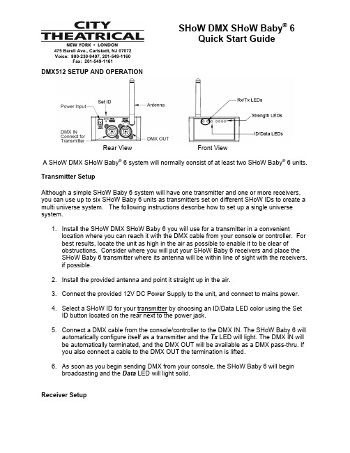
SHoW DMX SHoW Baby ® 6Quick Start Guide475 Barell Ave., Carlstadt, NJ 07072Voice: 800-230-9497, 201-549-1160Fax: 201-549-1161DMX512 SETUP AND OPERATIONRear ViewFront View A SHoW DMX SHoW Baby ® 6 system will normally consist of at least two SHoW Baby ® 6 units.Transmitter SetupAlthough a simple SHoW Baby 6 system will have one transmitter and one or more receivers, you can use up to six SHoW Baby 6 units as transmitters set on different SHoW IDs to create a multi universe system. The following instructions describe how to set up a single universe system.1. Install the SHoW DMX SHoW Baby 6 you will use for a transmitter in a convenientlocation where you can reach it with the DMX cable from your console or controller. For best results, locate the unit as high in the air as possible to enable it to be clear ofobstructions. Consider where you will put your SHoW Baby 6 receivers and place the SHoW Baby 6 transmitter where its antenna will be within line of sight with the receivers, if possible.2. Install the provided antenna and point it straight up in the air.3. Connect the provided 12V DC Power Supply to the unit, and connect to mains power.4. Select a SHoW ID for your transmitter by choosing an ID/Data LED color using the SetID button located on the rear next to the power jack.5. Connect a DMX cable from the console/controller to the DMX IN. The SHoW Baby 6 willautomatically configure itself as a transmitter and the Tx LED will light. The DMX IN will be automatically terminated, and the DMX OUT will be available as a DMX pass-thru. If you also connect a cable to the DMX OUT the termination is lifted.6. As soon as you begin sending DMX from your console, the SHoW Baby 6 will beginbroadcasting and the Data LED will light solid.Receiver SetupYou will need at least one SHoW Baby 6 to use as a receiver.1. Install the SHoW Baby 6 you will use for a receiver in a convenient location where youcan reach it with a DMX cable to the device (or devices) it will be providing DMX for. Aswith the SHoW Baby 6 transmitter, locate the unit higher in the air for best results, andtry to place your SHoW Baby 6 receiver where its antenna will be within line of sight with the transmitter.2. Install the provided antenna and point it straight up in the air.3. Connect the provided 12V DC Power Supply to the unit, and connect to mains power.The SHoW Baby 6 will be configured as a receiver and the Rx LED will light.4. Select a SHoW ID by matching the ID/Data LED color to that of the transmitting SHoWBaby 6 you wish to receive DMX data from by using the button located on the rear of the unit next to the power jack. Transmitter and receiver SHoW ID colors must match forthem to communicate.5. Connect a DMX cable from the SHoW Baby 6 DMX OUT to the first DMX device youwant to provide DMX to. You can then continue to add up to 32 more DMX devices tothe chain. Like any other DMX system, be sure the last connected device in the chain is properly terminated.6. As soon as you begin broadcasting from the SHoW Baby 6 set up as your transmitter,the data will be received by the SHoW Baby(s) 6 set up as receiver(s) and thetransmitted DMX will be output from the receiver unit’s DMX OUT. The received signalstrength will be displayed on the four LO – RF Signal – HI LEDs. This four LED “meter”will light to show you your signal strength; a good wireless signal is three or more LEDs, and weaker signal is two or less.You can set up any number of additional SHoW Baby 6 units as receivers.Choosing SHoW IDsColor Green Cyan Magenta White Red Yellow SHoW ID 201 102 117 133 149 165Use Adaptivehopping(defaultselection) FullbandwidthbroadcastBroadcastlimited tolower endof bandBroadcastlimited tomiddle ofbandBroadcastlimited toupper endof bandBroadcastlimited toarea ofWi-Fichannel 14Please refer to the City Theatrical SHoW Baby 6 Wireless DMX Transceiver User’s Manual for more information, including information about safety and compliance, antenna options, and RDM operation.page 2 of 2。
DMX-K60.01
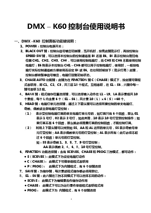
DMX – K60控制台使用说明书一、DMX –K60 控制面板功能键说明:1、POWER:控制台电源开关;2、BLACK OUT键:控制台信号输出切换键,当开机时,按亮此键批示灯,再按控制台SPEED SW键,可以选择本控制台的控制通道是E4还是E6。
E4表示控制台推拉电位器CH1、CH2、CH3、CH4,可以使用控制电脑灯,而CH5和CH6不能使用控制电脑灯;E6则表示本控制台CH1 – CH6都可以用于控制电脑灯,使用时,一般按电脑灯实际控制通道数方便使用而设定E4或E6。
在任何时候按下(批示灯亮)此键,控制台都将暂停信号输出,电脑灯回复初始状态。
3、CHASE AUTO功能键:此键为在FIMCTION键C(CHASE)模式下,按此键可做程式串联用,即C1、C2、C3,共三层18个程式。
互相串联,在S1 – S6,六键中每一键可串联12组。
4、BANK键:程式储存位置选择键,可以选择输入动作在L1 – L9、LA表示景组共10个景组,每个L内含景6个(S1 – S6),共计景10(L)ⅹ6(S)=60个。
5、HEAD键:电脑灯单元选择键,通过上下箭头键可以选择所要控制的单支电脑灯、奇数、偶数或全部电脑灯受控制:(1)表示受控制电脑灯具的单支电脑灯单元号码,如灯具只有6个回路,那么01 表示1号灯,02表示2号灯,如此类推,10表示10号灯受到控制操作;如果灯具不是6个回路,那么就必须推算灯具的控制回路,才能控制灯具。
(2)利用上下箭头键可以找到如SS、AA和AL这样的单元号,SS表示奇数号单元灯受控制;AA表示偶数单元号的灯受控制;AL表示所有(此灯必须不超过6个回路)单元号的灯受控制。
如:SS表示奇数1、3、5、7、9号灯受控制;AA表示偶数2、4、6、8、10号灯受控制。
6、FIMCTION功能选择键:含有SCENES、CHASE和PROG三种模式,都可动作:●S(SCENES):此模式下为设定电脑灯动作●C(CHASE):此模式下可做单组程式串联用●P(PROG):此模式下为内键程式,有6个按键选择7、SAVE键:为储存键,每次景或程式储存都必须用到它。
DMX中文说明书
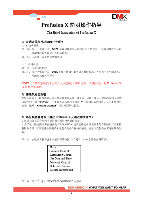
Profusion X简明操作指导The Brief Instruction of Profusion X1)正确开关机及功放的开关顺序1.1 启动系统第一步:按一下电源开关,DMX多媒体播放中心将按程序自检启动,多媒体播放中心将自动播放预先设定的音乐节目表。
第二步:依次打开各个功能区的功放1.2 关闭系统第一步:依次关闭功放第二步:按一下电源开关,DMX多媒体播放中心将进入暂停状态;再次按一下电源开关,系统将执行关闭程序NOTE: 严禁在系统尚未正常关闭的情况下切断电源。
否则可能引起Profusion X 或其他设备损坏2)音乐风格的改变在默认状态下,播放器显示屏会显示歌曲的标题,音乐家、风格、地区、定时模式和区域的日期/时间。
按“STYLE”上下键可音乐风格并且按“*”键确定新的风格。
显示屏会相应改变。
选择“Return to Schedule”可以回到默认状态。
3)各区域音量调节(通过Profusion X及通过功放调节)1 通过功放上的音量调节旋钮调节所对应区域的音量。
2 为了最大限度提高声音逼真度,DMX MUSIC建议使用功率放大器上的音量控制开关来控制回放音量。
可以通过导航菜单来分别改变各个区域的音量。
音量改变仅会在所选区域内生效。
第一步在歌曲名称和艺术家显示屏幕中按“*”进入DMM主菜单如图所示:Back>V olume ControlMessaging ControlSet Date and TimeNetwork ControlSchedule ControlDevice Information第二步按“*”进入“VOLUME CONTROL”主菜单。
第三步按NA VIGATION UP 和 DOWN键,滚动可选区域列表。
一旦选中合适区域,按“*”确定。
BACK>Zone1Zone2Zone3Zone4Mute Zone1Mute Zone2Mute Zone3Mute Zone4第四步如果选择MUTE,LCD屏幕将会显示如下:Zone1 V olumeMUTED如果选择Zone1,LCD屏幕会有如下显示:Zone1 V olume==============可以通过NA VIGATION UP或RIGHT键来提高音量或NA VIGATION DOWN或LEFT键来降低音量。
智能型 DMX录制播放控制器说明
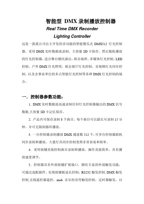
智能型DMX录制播放控制器Real Time DMX RecorderLighting Controller这是一款我公司自主开发的多功能的智能傻瓜式DMX512灯光控制器,采用DMX实时数据流录制,大容量SD卡保存,然后脱机播放的灯光控制器,适合舞台婚庆演出,娱乐场所,多媒体灯光控制,LED 控制,户外DMX灯光照明,展会展厅灯光控制,音视频灯光同步控制,以及企事业单位的多点智能灯光控制等各种DMX灯光控制的场合。
一.控制器参数功能:1.. DMX实时数据流高速录制任何灯光控制器输出的DMX信号数据,大容量SD卡记忆保存。
2. 产品共可保存录制8个曲目,每个曲目可以最长可录制15分钟,并可无限制循环播放。
3. 一台控制器录制播放DMX通道数512个,可多台控制器联机同步录制和播放,大量灯具同步控制变得非常容易和简单。
4.采用按键直接控制曲目录制和播放,操作直接简单,具有播放速度调节。
5.. 控制器具有外部按键扩展端口,拥有丰富的外部触发功能,可通过选配插件,实现按键板延长控制,RS232触发控制, DMX触发控制,无线遥控器遥控,midi音乐的音符触发控制,定时器触发,以及客户自定的方式触发控制。
5. 工作电压DC9-12V,电流200mA。
6..体积150mm X 95mm X 47mm图示面板功能键:REC键----------- 录制模式选择REC指示灯----- 录制模式状态显示PLAY键---------- 播放模式选择(开机默认播放模式)PLAY指示灯---- 播放模式状态显示STOP键----------- 录制或播放停止键STOP指示灯----- 录制或播放时运行状态指示灯Speed键----------- 播放速度调节键1-8 CUE键--------- 1-8个曲目录制或播放直选键Error指示灯------ 录制播放报错状态指示灯Dmx指示灯------ USB-DMX512灯光控制器信号指示灯图示背板接线In B --------------- 输入外部DMX信号端口Out B --------------- 外部DMX信号直通输出端口Out A --------------- DMX录制播放控制器主控输出端口Control ------------- USB-DMX512灯光控制器输出口或DMX信号外控触发输入口USB ---------------- USB-DMX512灯光控制器USB端口外控触发端口---- 键盘延长外部扩展端口选配外部触发插件输入端口二.录制模式录制保存需要的灯光控制程序本产品不同于目前常见的采用电脑制作编辑灯光或动画程序,再电脑联机下载到SD卡上,再插卡到控制器去播放。
DMX512中文使用说明书

DMX512中文使用说明书(2009-03-20 16:07:26)转载分类:灯光设备使用和技巧标签:灯光设备一、四位数码管说明:XXXX*第一位代表CHASE,共有6个*第二位代表SCENSE,共有8个*第三四位代表BANK,共有30个*设置MIDI通道时第三四位代表MIDI通道,共有16个MIDI通道*一个CHASE最多可以包含240个SCENSE*一个BANK最多可以包含8个SCENSE*一个SCENSE最多可以包含192个通道(也可以说是12个SCANNER) SCANNER1:通道1~通道16SCANNER2:通道17~通道32以此类推SCANNER12:通道181~通道192*一个SCANNER最多可以包含16个通道*调节滑杆时显示数值或者百分比二、操作时请注意数码屏的指示灯在什么状态。
*BLANKOUT*STEP*PROGRAM*MUSIC TIGGER*AUTO TIGGER三、DMX512面板功能说明1、SCANNERS按下SCANNER键,其旁边的LED灯亮,其中连接8个通道的输出可被调节,在SCENS运行时,如果可调电位器控制为OFF,则调节电位器不会影响通道输出,但如果可调电位器控制为ON,则通道输出会随相应的可调电位器的改变而改变;2、SCENS按健按下一个SCENS键可触发SCENS或存入一个SCENS,第二个数码管头显示SCENS1-8;3、可调电位器调节可调电位器改变DMX的通道输出大小,最小是0最大为255或者从0%-100%,可调电位器1-8控制连续的八个通道;4、PAGE/SELECT键选择PAGE A或PAGE B,PAGE A为每个SCANNER的前八个通道PAGE B为每个SCANNER的后八个通道5、SPEED SLIDER推动这个推杆调整走灯速度;6、FADE TIME SLIDER推动这个推杆调整FADE TIME;7、LED DISPLAY8、BANK按键(↑/↓)第三位和第四位数码管显示BANKS(01-30),按下↑/↓键,BANK增大或减小,显示的SCENS为该BANK里的SCENS;9、CHASE 1-CHASE 6键用于CHASES编程或CHASES运行的选择;10、PROGRAM键上电本机在走动运行状态,按下PROGRAM键盘2秒,编程指示灯闪动可编程SCENSR和CHASER,再按下PROGRAM键2秒,编程指示灯灭回到运行状态;11、MIDI/ADD键A、在运行状态按住MIDI键2秒,第3及第4位数码管闪动,通过↑或↓选择MIDI通道,再按MIDI键2秒结束MIDI通道的设置选择的MIDI通道被存贮;或者除↑/↓键以外的任何键都可结束MIDI通道的设置,不存贮所选取的MIDI通道;B、在编程状态,用于编辑;12、AUTO/DEL键A、在运行状态,按下AUTO/DEL键,自动触发指示灯亮,表示在自动触发状态,再按下AUTO键退出自动触发状态,自动触发指示灯灭;B、在编程状态,用于SCENS及CHASE编程;13、MUSIC/BANK COPY键A、在运行状态,按下MUSIC键,声音触发指示灯亮,可由声音触发SCENS,再按一下MUSIC键,声音触发指示灯灭,退出声音触发状态;B、在编程状态,用于SCENS及CHASE编程;14、TAPSYNC/DISPLAY键A:(1)、在AUTO运行状态,最后两次按下TAP SYNC/DISPLAY键决定SCENS运行的速率,最大时间为十分钟;(2)、不在AUTO运行状态,转换00-255或0%-100%;B:在编程状态(1)、对CHASE编程时,在步数显示和BANK显示之间转换;(2)、不在CHASE编程时转换00-255或0%-100%。
SHoW DMX SHoW Baby 6 无线DMX接收器与传输设备用户印刷版指南说明书
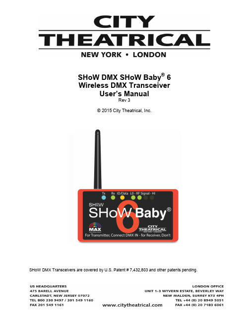
SHoW DMX SHoW Baby®6Wireless DMX TransceiverUser’s ManualRev 3© 2015 City Theatrical, Inc.SHoW DMX Transceivers are covered by U.S. Patent # 7,432,803 and other patents pending.ContentsRadio Compliance Information (3)5792M SHoW DMX Radio CE Declaration of Conformity (6)System Compliance Information (7)Safety Notices (7)Introduction (8)SHoW DMX SHoW Baby®6 Neo Settings (8)SHoW DMX SHoW Baby®6 Antennas (9)DMX512 Setup and Operation (9)Transmitter Setup (9)Receiver Setup (10)RDM Operation (10)Installing the Mounting Bracket (11)Radio Compliance Information5792M SHoW DMX Neo® Radio TransceiverFCC ID: VU65792IC ID: 7480A5792FCC Part 15This equipment has been tested and found to comply with the limits for a Class B digital device, pursuant to part 15 of the FCC Rules. These limits are designed to provide reasonable protection against harmful interference in a residential installation. This equipment generates, uses and can radiate radio frequency energy and, if not installed and used in accordance with the instructions, may cause harmful interference to radio communications. However, there is no guarantee that interference will not occur in aparticular installation.If this equipment does cause harmful interference to radio or television reception, which can be determined by turning the equipment off and on, the user is encouraged to try to correct the interference by one or more of the following measures:•Reorient or relocate the receiving antenna.•Increase the separation between the equipment and receiver.•Connect the equipment into an ou tlet on a circuit different from that to which the receiver is connected.•Consult the dealer or an experienced radio/ TV technician for help.Radio Frequency NotificationsFCC NotificationsRF Radiation The Product is an intentional radiator of Radio Frequency (RF) energy. In order to limit RF exposure to personnel in the immediate area, the Product should be located and installed such that a separation of at least 20 centimeters is maintained between the Product’s antenna and personnel in the vicinity of the device.Modification WarningCaution: changes or modifications to this equipment, not expressly approved by City Theatrical Inc. could void the user’s authority to operate the equipment.Industry Canada NotificationsThis Class B digital apparatus complies with Canadian ICES-003. Operation is subject to the following two conditions: (1) this device may not cause interference, and (2) this device must accept any interference, including interference that may cause undesired operation of the device.Cet appareil numérique de la classe B est conforme à la norme NMB-003 du Canada.Product Installation and Configuration Guide © City Theatrical Inc. 20075792M Approved AntennaTo reduce potential radio interference to other users, the antenna type and its gain should be so chosen that the equivalent isotropically radiated power (e.i.r.p.) is not more than that permitted for successful communication.This device has been designed to operate with the antennas listed below. Antennas not included in this list or having a gain greater than 6 dB are strictly prohibited for use with this device. The required antenna impedance is 50 ohms.5792M FCC/IC Approved Antennas:5792M CE Approved Antennas:CE Mark ConformityCity Theatrical Inc. declares that this product conforms to the specifications listed in this manual, following the provisions of the European R&TTE directive 1999/5/EC:City Theatrical Inc. vakuuttaa täten että dieses produkt tyyppinen laite on direktiivin 1999/5/EY oleellisten vaatimusten ja sitä koskevien näiden direktiivien muiden ehtojen mukainen.City Theatrical Inc. déclare que le produit est conforme aux conditions essentielles et aux dispositions relatives à la directive 1999/5/EC.•EN 301 489-1, 301 489-17 General EMC requirements for Radio equipment.•EN 60950 Safety•EN 300 328 Technical requirements for Radio equipment.CAUTION—This equipment is intended to be used in all EU and EFTA countries.Outdoor use may be restricted to certain frequencies and/or may require a license for operation. Contact local Authority for procedure to follow.Note: ESD precautions should be used when attaching or removing the antenna.Note: Combinations of power levels and antennas resulting in a radiated power level of above 100 mW equivalent isotropic radiated power (EIRP) are considered as not compliant with the above mentioned directive and are not allowed for use within the European community and countries that have adopted the European R&TTE directive 1999/5/EC. For more details on legal combinations of power levels and antennas, contact City Theatrical Inc.Do not use this product near water, for example, in a wet basement or near a swimming pool.Avoid using this product during an electrical storm. There may be a remote risk of electric shock from lightning.Product Installation and Configuration Guide © City Theatrical Inc. 2011Q52 Regulatory informationRadio Frequency NotificationsBelgique Dans le cas d'une utilisation privée, à l'extérieur d'un bâtiment, au-dessus d'un espace public, aucun enregistrement n'est nécessaire pour une distance de moins de 300m. Pour une distancesupérieure à 300m un enregistrement auprès de l'IBPT est requise. Pour une utilisation publique àl'extérieur de bâtiments, une licence de l'IBPT est requise. Pour les enregistrements et licences, veuillez contacter l'IBPT.France 2.4 GHz Bande : les canaux 10, 11, 12, 13 (2457, 2462, 2467, et 2472 MHz respectivement) sont complétement libres d'utilisation en France (en utilisation intérieur). Pour ce qui est des autres canaux, ils peuvent être soumis à autorisation selon le départment. L'utilisation en extérieur est soumis à autorisation préalable et très restreint. Vous pouvez contacter l'Autorité de Régulation des Télécommunications (http://www.art-telecom.fr) pour de plus amples renseignements.5792M SHoW DMX Radio CE Declaration of ConformitySystem Compliance InformationThe 5702M SHoW DMX SHoW Baby®6 Transceiver is CE Certified Standards Applied:BS EN 60950-1:2002 incorporating Corrigendum No. 1 and Amendment No. 1EN 55203-1: 1996EN 55203-2: 1996EN 301 489-1 V1.4.1EN 301 489-3 V1.4.1Products Conform to CE Marking Directive 93/68/EECAll SHoW DMX models are RoHS compliantSafety NoticesPlease read this entire manual before using your new equipment. Please keep the manual in a safe place so you can refer to it in the future as required.The SHoW DMX System is intended for use only by qualified professionals. Connection, installation, and hanging of this equipment must be performed in accordance with all pertinent local, regional, and national safety codes and regulations.SHoW DMX equipment is intended for indoor use only unless specified for outdoor use.Keep the equipment dry! Do not operate the equipment if it gets wet!Do not operate in excessive heat/direct sunlight.Be sure installation provides adequate ventilation.There are no user-serviceable parts inside! Refer to qualified service personnel!RF Exposure: The antenna(s) used for this transmitter must be installed to provide a separation distance of at least 20cm from all persons and must not be collocated or operating in conjunction with any other antenna or transmitter.IntroductionThank you for usi ng City Theatrical’s SHoW DMX SHoW Baby®6 Wireless DMX/RDM Transceiver.The SHoW DMX SHoW Baby 6 represents a breakthrough in plug-and-play wireless DMX and RDM transmission, and can be used either as a wireless DMX transmitter or receiver. All you need now to set up a SHoW DMX wireless DMX system is two SHoW DMX SHoW Babys and two minutes!The SHoW DMX SHoW Baby 6 features include:∙SHoW DMX Neo® 2.4GHz Frequency Hopping Spread Spectrum (FHSS) Radio∙Wirelessly broadcast and receive a full Universe (512 slots) of DMX∙Robust wireless DMX512 and RDM data transmission∙Six Possible SHoW IDs – including the original SHoW Baby 201∙Full Compatibility with previous SHoW Babys∙Extremely low 7mS max latency∙RDM proxy and responder functions∙Instant plug-and-play configuration: For a Transmitter, connect DMX IN, for a Receiver, don’t!∙72mW ETSI broadcast power (with 2dBi Antenna)∙Mount ing bracket for installation with C-Clamp or similar hanging hardware∙Included CL2 Power Supply∙Included 2dBi Omni-directional Antenna∙Neutrik® 5P XLR Connectors for DMX IN and DMX OUT (3 pin in 5702M-3)Every effort has been made to anticipate your questions in this manual, but if you have any questions that are not answered here, or you want to discuss a special application, please feel free to contact us directly at City Theatrical.SHoW DMX SHoW Baby6 Neo SettingsThe SHoW DMX SHoW Baby6 uses the 5792 SHoW DMX Neo Radio Module. It is permanently configured with six SHoW ID options for Adaptive Spread Spectrum Frequency Hopping and Neo Low Latency broadcast mode. Using RDM, you can adjust SHoW ID, adjust the broadcast power, edit the RDM Device Label, and enable or disable RDM traffic. No other settings are adjustable. The SHoW ID can also be changed by pressing the small button on the back of the SHoW DMX SHoW Baby®6labeled “SET ID”.SHoW DMX SHoW Baby 6 AntennasThe SHoW DMX SHoW Baby6 is shipped with a 2dBi o mni directional antenna. Any of the approved antennas listed above may be used with the SHoW DMX SHoW Baby®6 (please note the special installation requirements for use with the CTI # 5636 14 dBi Yagi Antenna).ETSI power settings for all 5792M SHoW DMX Neo Radio module equipped products, including the SHoW DMX SHoW Baby6, are based on use with the CTI 5630 5 dBi Omni Antenna. ETSI power and range will vary with the antenna used. Contact your dealer or City Theatrical for more information.DMX512 Setup and OperationRear View Front ViewA SHoW DMX SHoW Baby 6 system will normally consist of at least two SHoW Baby6 units.Transmitter SetupAlthough a simple SHoW Baby 6 system will have one transmitter and one or more receivers, you can use up to six SHoW Baby 6 units as transmitters set on different SHoW IDs to create a multi universe system. The following instructions describe how to set up a single universe system.1.Install the SHoW DMX SHoW Baby 6 you will use for a transmitter in a convenientlocation where you can reach it with the DMX cable from your console or controller. For best results, locate the unit as high in the air as possible to enable it to be clear ofobstructions. Consider where you will put your SHoW Baby 6 receivers and place theSHoW Baby 6 transmitter where its antenna will be within line of sight with the receivers, if possible.2.Install the provided antenna and point it straight up in the air.3.Connect the provided 12V DC Power Supply to the unit, and connect to mains power.4.Select a SHoW ID for your transmitter by choosing an ID/Data LED color using the Set IDbutton located on the rear next to the power jack.5.Connect a DMX cable from the console/controller to the DMX IN. The SHoW Baby 6 willautomatically configure itself as a transmitter and the Tx LED will light. The DMX IN will be automatically terminated, and the DMX OUT will be available as a DMX pass-thru. If you also connect a cable to the DMX OUT the termination is lifted.6.As soon as you begin sending DMX from your console, the SHoW Baby 6 will beginbroadcasting and the Data LED will light solid.Receiver SetupYou will need at least one SHoW DMX SHoW Baby 6 to use as a receiver.1.Install the SHoW Baby 6 you will use for a receiver in a convenient location where youcan reach it with a DMX cable to the device (or devices) it will be providing DMX for. Aswith the SHoW Baby 6 transmitter, locate the unit higher in the air for best results, and try to place your SHoW Baby 6 receiver where its antenna will be within line of sight with the transmitter.2.Install the provided antenna and point it straight up in the air.3.Connect the provided 12V DC Power Supply to the unit, and connect to mains power.The SHoW Baby 6 will be configured as a receiver and the Rx LED will light.4.Select a SHoW ID by matching the ID/Data LED color to that of the transmitting SHoWBaby 6 you wish to receive DMX data from by using the button located on the rear of the unit next to the power jack. Transmitter and receiver SHoW ID colors must match forthem to communicate.5.Connect a DMX cable from the SHoW Baby 6 DMX OUT to the first DMX device youwant to provide DMX to. You can then continue to add up to 32 more DMX devices to the chain. Like any other DMX system, be sure the last connected device in the chain isproperly terminated.6.As soon as you begin broadcasting from the SHoW Baby 6 set up as your transmitter, thedata will be received by the SHoW Baby(s) 6 set up as receiver(s) and the transmittedDMX will be output from the receiver unit’s DMX OUT. The received signal strength willbe displayed on the four LO – RF Signal – HI LEDs. This four LED “meter” will light toshow you your signal strength; a good wireless signal is three or more LEDs, and weaker signal is two or less.You can set up any number of additional SHoW Baby 6 units as receivers.RDM OperationRDM stands for Remote Device Management. RDM is a lighting control protocol enhancement to DMX512 specified by PLASA (formerly ESTA); the official name is ANSI/ ESTA E1.20, Entertainment Technology - Remote Device Management over USITT DMX512. To learn more about RDM, a good place to start is the Wikipedia article on RDM (lighting) at: /wiki/RDM_(lighting)SHoW DMX SHoW Baby 6 is fully enabled as an RDM proxy system, so you can use RDM to manage your SHoW DMX SHoW Baby 6 system and any connected RDM responders thatare downstream of the system.In order to use RDM, you will also need an RDM controller or a lighting control console with a built-in RDM controller.SHoW DMX SHoW Baby®6 supports the following read-only PIDs:PROXIED_DEVICE_COUNTPROXIED_DEVICES_ENHANCEDSUPPORTED_PARAMETERSPARAMETER_DESCRIPTIONPRODUCT_DETAIL_ID_LISTDEVICE_MODEL_DESCRIPTIONMANUFACTURER_LABELFACTORY_DEFAULTSSOFTWARE_VERSION_LABELSENSOR_DEFINITIONSENSOR_VALUE, OUTPUT_POWERSHoW DMX SHoW Baby®6 supports the following editable PIDS:SHoW ID(editable, 201, 102, 117, 133, 149, 165)DEVICE_LABEL (editable)RDM_TRAFFIC_ENABLE (editable, 01 = enable, 00 = disable)OUTPUT_POWER (editable, 00=1mW, 01=14mW, 02=28mW, 03=72mW)In order to allow RDM traffic and discovery and control of connected Responders you must enable RDM Traffic (Set RDM_TRAFFIC_ENABLE to 01).Note that DMX transmission fidelity may be slightly reduced when RDM Traffic is enabled. Installing the Mounting BracketThe SHoW DMX SHoW Baby 6is provided with a Mounting Bracket for use with ½”theatri cal mounting hardware like a C-Clamp.Mount the Bracket on the SHoW DMX SHoW Baby 6 using the 3 provided 8-32 x 1/2" Pan Head Philips screws.。
德国坦克 声卡,DMX 6Fire USB,中文说明介绍模板之欧阳家百创编

V 1.0欧阳家百(2021.03.07)2009.04.06使用手册DMX 6Fire USBTerraTec DMX 6Fire USB 使用手册DMX 6 Fire USB设备连接介绍 2前面 (2)背面 (4)模拟输出 5LINE OUT 1/2, 3/4, 5/6 (背面) (5)耳机输出(前置) (5)驱动 5控制面板 5混音器 (6)音量 (6)信号 (6)绕送 (7)输出和设定 (7)音量 (7)频率设定 (8)设备设定 (8)场景 (9)其它 (9)TerraTec DMX 6Fire USB 使用手册DMX 6 Fire USB设备连接介绍DMX6 Fire USB 音效界面提供你连接许多专业录音外围设备和Hi-Fi设备。
前面1. 麦克风接口(XLR-1/4" or 6.3 mm 复合式接口)这个插座接受XLR接头和需要幻象电源(通常是电容式麦克风)的专业麦克风,和”一般” 耳机插头。
这个接口与背板上Line In 1接口是同时只能择一使用,而且假如XLR or 1/4" (6.3 mm)插头插上时,会自动重新重导信号路径(自动优先选择),此时在背板的Line In 1 和 Line In 2 会自动关掉。
2. 耳机的音量控制当你将耳机插入进去,先把音量转到最左边0的位置,否则可能相当大声。
你可以在插入耳机后再转大声。
3. 耳机接口如上所述:插上耳机之前将音量控制转到最低。
这个接口仅会送出Line Out1/2的信号。
4. 麦克风控制的LED指示灯。
LED灯是提供视觉上监看麦克风的录音。
蓝灯代表”有信号” ,假如看到亮红色LED,请将Gain 1控制转小。
红色LED灯亮时代表是削峰失真,造成了录音信号失真。
5. 麦克风孔的音量控制控制前置放大的信号在麦克风输入端。
同样的,麦克风插入控制在麦克风输入端的信号前级放大。
6. 48伏幻象电源:当你连接电容式麦克风时拨到”on”。
DMXking ultraDMX Pro Interface 用户手册说明书

ultraDMX Pro InterfaceUSER MANUAL1.Introduction (1)Main Features (1)2.Exterior View (2)Front View (2)Status LED Table – USB DMX mode (2)Status LED Table – Splitter mode (3)3.Installing the FTDI Driver (3)4.Configuration utility (4)patible Software (6)Controllers (6)Media Servers / VJ (7)Visualizers (7)6.Updating Firmware (8)Firmware Updater (8)7.Technical Specifications (9)8.Warranty (9) Hardware Limited Warranty (9)munications Protocol (9)10.Declarations (FCC & CE) (10)Federal Communications Commission (FCC) Declaration of Conformity (10)EEC Declaration (10)1.The ultraDMX Pro product is a robust 3 universe bi-directional DMX512 interface communicating with the host computer over USB. An onboard Atmel microcontroller ensures complete timing accuracy and no flickering effects no matter what your computer is doing. Device communication using FTDI virtual COM port (VCP) or direct (D2XX) drivers allows use of any mainstream OS.Operation in 3 universe mode (1 in, 2 out) requires compatible software. Enhanced mode is disabled automatically when standard (Enttec USB Pro) commands are received and only 1 universe operation can be achieved however all outputs are available essentially making this device a USB Pro + DMX Splitter in one.A standalone mode is also available for DMX512 splitter functionality making the ultraDMX Pro product truly universal. New in firmware v1.2 is DMX RX Throttling and DMX TX Maximum Compatibility mode which extends DMX512 timing. These features bring the same functionality as a DMX Decelerator into your ultraDMX device at zero additional cost.ultraDMX Pro operating modes:Switching between MODE 1 and MODE 2 is fully automatic and determined by your lighting control software. If enhanced mode DMX output commands are sent to the ultraDMX Pro it enters enhanced mode and conversely when standard DMX output commands are sent compatibility mode is triggered.MODE 3 standalone splitter can only be enabled and disabled using the ultraDMX Configuration Utility. Note also manufactures a dedicated 4 port splitter, the ultraDMX Split.MAIN FEATURES-Fully isolated between all XLR connectors and USB interface-DMX transmit timing adjustment settings to “fix” issues with non-compliant DMX lighting gear-DMX receive rate throttling option to ensure receiving software isn’t overloaded with too many frames per second -Supported operating systems: Windows, Mac OS, Linux-DMX512 Transmitter and Receiver (OUT and IN)-Tough metal enclosure with multiple mounting options-Available with 3 pin or 5 pin XLR connectors, no adapter purchase required.-ANSI E1.11-2008 compliant (DMX512-A).-E1.11 Higher Protection Level “DMX512-A Protected” device.-Internal double buffered DMX512 streams resulting in zero lost frames.-Fully compatible with software suitable for ENTTEC USB Pro (except D-Pro sorry, use our Art-Net devices instead) -Standalone DMX512 Splitter mode. Power with 5V USB supply.-Configuration utility (Windows .NET 3.5 – OS X version available Q3 2013).2.FRONT VIEWOne 5pin or 3pin XLR male connector for DMX512 input and 4x 5pin or 4x 3pin or 2x 5pin+3pin XLR female connectors for DMX512 output grouped as 2 pairs. USB B connector for host interface.STATUS LED TABLE – USB DMX MODESTATUS LED TABLE – SPLITTER MODE3.INSTALLING THE FTDI DRIVERTo maximize compatibility with existing software an FTDI ( ) FT245RL device provides USB 2.0 Full Speed interfacing for the ultraDMX unit. Drivers are available directly from FTDI and in most cases the VCP (Virtual COM Port) driver should be used although both D2XX and VCP are installed by default on Windows OS. The latest drivers are available from /Drivers/VCP.htmPlease refer to the installation guides at /Documents/InstallGuides.htm and note the process involved installs 2 devices, a USB serial device followed by USB virtual COM port. All required files are included in the driver installation file.On occasion you may wish to change the COM port number an ultraDMX unit has been assigned by Windows. This can be done through the Device Manager applet by right clicking on the USB Serial Port of interest (unplug/re-plug the unit and observe device manager COM port list if unsure which one is your ultraDMX) then select properties, Port Settings tab, Advanced button and finally choose the desired COM Port Number.4.CONFIGURATION UTILITYThe ultraDMX Configuration utility provides access to DMX512 timing and other advanced parameters along with a simple DMX display control providing output/transmit and input/receive operation testing without any additional software.The Advanced tab facilitates adjustment of some more specialized parameters. You can alter what the ultraDMX Pro unit reports when queried with a Label 3 command. This can be useful when software detects functionality based on the Label 3 ‘FW major’ variable. Default settings are Label 3 FW major = 1, Label 3 FW minor = 44 (report ENTTEC USB Pro non-RDM firmware).Device UID cannot be altered and USB Retry Count should be left at 5 unless advised by support.Choose between ultraDMX Pro Mode Standard or Splitter. The later forces the unit to ignore any DMX data sent over USB and instead just receive DMX512 on the male XLR and re-transmit on all 4 female XLRs. Note the Break and Mark After Break times are re-generated and not the same as the received DMX512 data stream and in conjunction with DMX TX Mode and DMX RX Throttle the ultraDMX Pro can re-time DMX streams just like a DFD DMX Decelerator.Options for DMX TX Mode will override parameters set by your lighting software resulting in guaranteed longer Break and MAB times along with slower DMX transmit rates and even extra delays between channel characters which some fixtures like the Chauvet ColorStrip need in order to function correctly.DMX RX Throttle setting will selectively drop incoming DMX frames to produce the indicated frame rate being forwarded (over USB in Standard mode or sent direct to DMX output ports in Splitter mode). When set to None the full DMX RX rate is forwarded however some software applications may have issues handling high rates, Laser Show Designer QuickShow is known for this problem. This is also useful to for re-timing a DMX stream when in Splitter mode.Select View | DMX Display for the simple DMX512 test control. To generate a DMX512 output stream click Transmit then select one of the 6 Transmit Options. When in Manual mode you can click on any of the channels (represented by small boxes with hexadecimal channel level inside) to set ON level and double click to set zero. The mouse scroll wheel adjusts a channel by a defined increment. Channel number increases left to right, top to bottom and the roaming tool tip provides information about a specific channel.Both the ON level and mouse wheel step can be set by right clicking anywhere within the black display area. Number of channels transmitted and the refresh rate can be adjusted using the applicable sliders adjacent to transmit options.PATIBLE SOFTWAREDMX512 is the most commonly used lighting control protocol with roots in simple theatrical light dimming. These days almost any lighting or stage effect equipment may be controlled using DMX512 (with explicit exclusion of anything involving potentially dangerous operations such as pyrotechnics) including moving lights, LED screens, fog machines and laser displays.The ultraDMX Pro unit is designed for use with computer based show control software. It replaces an entire lighting console allowing the user to perform sophisticated shows with little more than a laptop. There are many free and commercial software packages available and by selecting either ultraDMX Pro or, if unavailable, Enttec USB Pro as your DMX device full compatibility is guaranteed.6.A built in boot loader permits updating of the ultraDMX Pro firmware. Note only signed encrypted firmware files from can be successfully loaded to ensure you won’t brick your device by accident.FIRMWARE UPDATERThe ultraDMX Configuration utility includes a firmware updater function and the latest version contains all ultraDMX variant firmware files.1.Close any applications that may be using the ultraDMX Pro unit.2.Start the ultraDMX Configuration application.3.Select the applicable COM port, you may have more than one ultraDMX unit connected however only one may beupdated at a time.4.In the Firmware tab the device Serial Number is displayed. Check this matches the device you planned to update.5.Select the Firmware File – usually the most recent file which should automatically be displayed first.6.Click the Upload Firmware button and observe progress bar. Programming takes around 15 seconds, be sure not todisconnect the ultraDMX unit during this process.Future firmware releases for this product will be in the form 0080-500-VersionMajor.VersionMinor.enc∙Dimensions: 250x60x44mm (WxHxD)∙Weight: 0.45kg∙DMX512 connector: 5 or 3 pin XLR male and female.∙Internal DMX512 line termination on IN connector.∙USB connector: USB-B socket∙DMX512 Frame Rate and Break Timing: Adjustable∙DMX512 Port Protection: DMX512-A Protected as per E1.11-20088. HARDWARE LIMITED WARRANTYWhat is coveredThis warranty covers any defects in materials or workmanship with the exceptions stated below.How long coverage lastsThis warranty runs for one year from the date of shipment from an authorized distributor.What is not coveredFailure due to operator error or incorrect application of product. Opening the unit voids the warranty.What will do will repair or replace, at its sole discretion, the defective hardware. Return shipping costs from our service facility in New Zealand shall be free of charge.How to obtain serviceContact directly by email ***************** or telephone +64(9)3794836 (UTC+12)9.The ultraDMX Pro uses ENTTEC’s DMX USB Pro Widget API Sp ecification 1.44 (as used for ENTTEC DMX USB Pro).DMXking has added several extensions to cater for additional output universes and other product identification data.Label = 100 Output Only Send DMX Packet Request Universe 1 on outputs 1 & 2 (same format as label 6)Label = 101 Output Only Send DMX Packet Request Universe 2 on outputs 3 & 4 (same format as label 6)When Label 6 data is received the ultraDMX Pro reverts back to standard mode and outputs 1 universe data on outputs 1,2,3&4.All USB DMX units also support Device Manufacture and Device Name extensions as detailed here: /index.php/USB_Protocol_ExtensionsFEDERAL COMMUNICATIONS COMMISSION (FCC) DECLARATION OF CONFORMITYResponsible Party: JPK Systems LimitedPO Box 493Pukekohe 2340New Zealanddeclares that the product ultraDMX Pro complies with Part 15 of the FCC rules.Operation is subject to the following two conditions: (1) This device may not cause harmful interference, and (2) this device must accept any interference received, including interference that may cause undesired operation.This equipment has been tested and found to comply with the limits for a class B digital device, pursuant to Part 15 of the FCC rules. These limits are designed to provide reasonable protection against harmful interference in a residential installation. This equipment generates, uses and can radiate radio frequency energy and, if not installed and used in accordance with the instructions, may cause harmful interference to radio communications. However, there is no guarantee that interference will not occur in a particular installation. If this equipment does cause harmful interference to radio or television reception, which can be determined by turning the equipment off and on, the user is encouraged to try to correct the interference by one or more of the following measures:-Reorient or relocate the receiving antenna.-Increase the separation between the equipment and the receiver.-Connect the equipment into an outlet on a circuit different from that to which the receiver is connected.-Consult the dealer or an experienced radio/TV technician for help.EEC DECLARATIONWeJPK Systems LimitedPO Box 493Pukekohe 2340New Zealanddeclare under our sole responsibility that our product ultraDMX Pro conforms to the requirements of Council Directives 89/336/EEC and 73/23/EEC and therefore complies with the requirements of Council Directive 73/23/EEC, (The Low Voltage Directive) on the harmonisation of the laws of Member States relating to electrical equipment designed for use within certain voltage limits as amended by Article 13 of Council Directive 93/68/EEC∙EN 55103-1∙EN 55103-2∙EN 60065Signed: Jason KyleDate: 9 September 2011 Position: Managing Director。
DMX Constant Current Decoder PX706-1050说明书
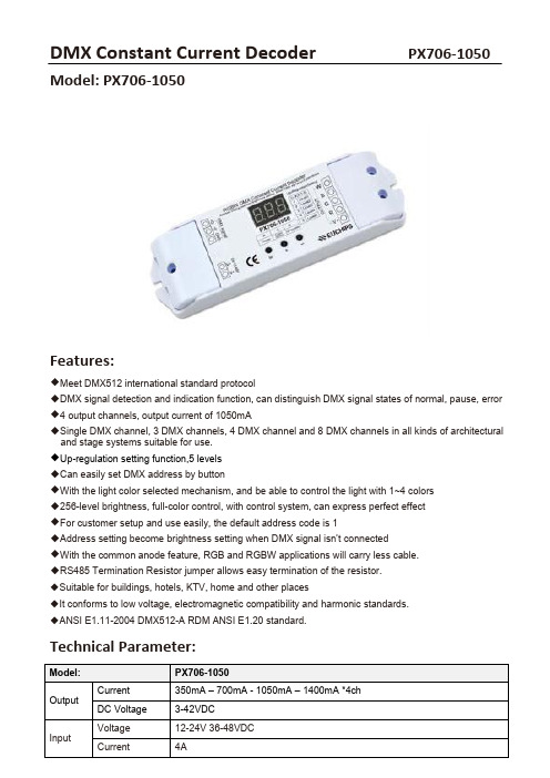
Model: PX706‐1050Features:◆Meet DMX512 international standard protocol◆DMX signal detection and indication function, can distinguish DMX signal states of normal, pause, error ◆4 output channels, output current of 1050mA◆Single DMX channel, 3 DMX channels, 4 DMX channel and 8 DMX channels in all kinds of architectural and stage systems suitable for use.◆Up-regulation setting function,5 levels◆Can easily set DMX address by button◆With the light color selected mechanism, and be able to control the light with 1~4 colors◆256-level brightness, full-color control, with control system, can express perfect effect◆For customer setup and use easily, the default address code is 1◆Address setting become brightness setting when DMX signal isn’t connected◆With the common anode feature, RGB and RGBW applications will carry less cable.◆RS485 Termination Resistor jumper allows easy termination of the resistor.◆Suitable for buildings, hotels, KTV, home and other places◆It conforms to low voltage, electromagnetic compatibility and harmonic standards.◆ANSI E1.11-2004 DMX512-A RDM ANSI E1.20 standard.Technical Parameter:•Dimension(mm)•Wiring instruction:Installation Interface Description:◆DMX signal interfacePlease pay attention to the polarity of DMX Signal. If DMX signal isn't connected correct, follows error will display:1.There is no DMX signal, current address ,current setting current (C ‐ 1) and current start light setting (U ‐X) will be displayed on LED by loop and interval 2S.2.The DMX signal is paused, current address, current setting current (C ‐ 1) and current start light setting (U ‐X) and P will be displayed on LED by loop and interval is 2s.3.The DMX signal is normal, current address be displayed only.◆Power input interfaceDC 12-48V input, supply power for decoder and the lamps it takes.◆Address setting keysAddress can be saved automatically, address can be recovered when next power on.1.Key "M", Used to enter the menu or return to the menu. Long press this key for 3S, enter the menu option. At this point the light of LED digital tube bottom right of the comma will turn on, Press button + or ‐ to select the options you need to set, Press the M bu tton to enter the settings. Press the M key again to exit the current submenu.2.Into the A option (Address code option), Buttons + for address plus, according to the address of each cumulative one. Long press button, the address code will quickly flip.The largest address is 511. Button ‐ used to address less, Short pressing button the address decreasing 1 one time, Long press button, the address code will quickly flip Minimum address 0. 3.Not receive DMX signal can be used as a manual dimmer, current address code is the brightness level.(This is a optional function)Note: The factory default address code is set to 1.4.Into the U option (brightness increase option), there are five brightness increased. For each additional, representing an increase of five brightness.◆Drive output interfaceTotal positive drive, With a V + interface and 4‐channel R, G,B and W output interface, Can be accessed by the module of a variety of full‐color and monochrome module automatically adjust the output current of the lamp module to loadNOTE: For full‐color module of male connector, can directly connect the positive line and the R, G, B ,W control line to the decoder output interface pin.For Monochrome modules, can connect the positive line to the decoder output interface V+ feet. Negative line according to the color of the module connected to the decoder output interface of the R, G, B,W pin.Several colors monochrome module received with a decoder, Shall their line receiving the output of the decoder interface V+ pin.Installation Notes1.Input voltage must be fit the product working voltage2.Do not overload3.Installed in a ventilated and dry environment4.Before commissioning of the power, should ensure that all wiring is correct before electricity.5.If failure, do not secretly maintenance, please contact the supplier.。
- 1、下载文档前请自行甄别文档内容的完整性,平台不提供额外的编辑、内容补充、找答案等附加服务。
- 2、"仅部分预览"的文档,不可在线预览部分如存在完整性等问题,可反馈申请退款(可完整预览的文档不适用该条件!)。
- 3、如文档侵犯您的权益,请联系客服反馈,我们会尽快为您处理(人工客服工作时间:9:00-18:30)。
LED CONTROL SYSTEM
◆概述
1、全系列的SD卡控制器均可加装DMX解码功能。 2、遵从DMX512协议,能被标准的DMX512控制台控制。 3、通过加装的外置的XLR标准接口实现与DMX控制台
及其他解码设备的连接。 4、占用六个连续通道,设定范围可从1到99。 5、支持99种图案模式。 6、兼容联机(DMX控台控制)及脱机控制。 7、通道地址及模式自动记忆。
模式等参数,声/音控数据由主机收集和处理,并发 向从机。 2、从机的数码管的速度显示0,音量和主机显示的一样, 模式为0(自动模式)时,主机显示0,从机显示实际 播放的模式。 3、请使用我司制作的网线或符合T568A、T568B标准的 直连网线。
◆交流同步
1、此速度是根据客户负载护栏管米数而定,小于实际 速度的数值不显示。
控台控制 ◆ 控制器地址设置 1、首先按控制器的“自动”键,将模式设置为"0",再按一次“模式-”键,控制器的数码管显示"dx xx",
表示进入了地址设置状态。 2、设置控制器地址,按“自动”键地址减一,按“速度”键地址加一。其中“xxx”是控制器地址。
地址设置公式是:(n-1)*6+1。n代表第n台控制器。 3、地址设置完后,按模式“+”或模式“-”按纽,返回速度模式显示状态。 ◆ 使用DMX控台改变音量、速度、模式(方式1) 1、以地址为“d001”的控制器为例,通道1控制“音量”,通道2控制“速度”(速度值最大是12,无交流同步功能)。
通道3、4控制模式十位。把控台通道3的滑杆推到上顶代表5,拉到底代表0(类似于算盘的上面的珠子); 将通道4的推动滑杆到最顶代表4,中间分别为3,2和1,拉到最底代表0,将通道3和通道4的数值相加 就得到模式的十位的值。通道5和通道6控制模式个位,设置方法与十位的相同。 2、若地址设置为“d007”,则通道7控制音量,通道8控制速度,通道9至12控制模式,如此类推。
◆连线示意图
1、连线标准: 3P卡龙接口,Pin1接地,Pin2接负,Pin3接正。
2、公口为接收端,接受控制台的DMX信号, 母口是传递端,连接其他解码器的公端。
3、SD卡控制器用交流220V供电。
◆基本操作
脱机控制 1、按“模式+”或“模式-”按钮,左边显示窗“dx”转为两位数的模式序列,即进入脱机模式。 2、用户可通过控制面板上的“速度”和“模式”按钮,可进行模式的选择和速度的调节。 3、模式为0时,是自动循环模式。 4、模式记忆功能:关控制器,重新上电,会直接按关机前的模式及速度状态运行。 5、通过按“模式-”(或“模式+”)按钮至主控屏幕显示“dx xx”可恢复联机状态。
2、按控制盒面板【速度】键调节播放的速度,数值越大, 速度越慢。 速度显示值 普通模式 1 2 3 4 5 6 7 8 9
思域科技有限公司
版权所有
推杆图标示意
通道 1 2
音速
99
88
77
推杆位
6 5
6 5
44
33
22
11
3
4
5
6
模式(十位) 模
3
3
2
2
1
1
0
0
0
0
推杆图标例:
通道 1
2
音速
●
3456 模式(十位)模式(个位)
●
●
通道 1 音
推杆位 ●
推杆位 5
●●
23456 速 模式(十位)模式(个位)
5 8
3
00
DMX控台控制+级联 1、通过主机上的按钮控制主机和从机上的音量、速度、
