TC4054(USB充电器)
lp4054充电芯片
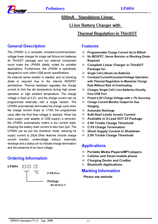
600mA Standalone LinearLi-Ion Battery Charger withThermal Regulation in ThinSOTGeneral DescriptionThe LP4054 is a complete constant-current/constant- voltage linear charger for single cell lithium-ion batteries. Its ThinSOT package and low external component count make the LP4054 ideally suited for portable applications. Furthermore, the LP4054 is specifically designed to work within USB power specifications.No external sense resistor is needed, and no blocking diode is required due to the internal MOSFET architecture. Thermal feedback regulates the charge current to limit the die temperature during high power operation or high ambient temperature. The charge voltage is fixed at 4.2V, and the charge current can be programmed externally with a single resistor. The LP4054 automatically terminates the charge cycle when the charge current drops to 1/10th the programmed value after the final float voltage is reached. When the input supply (wall adapter or USB supply) is removed, the LP4054 automatically enters a low current state, dropping the battery drain current to less than 2µA. The LP4054 can be put into shutdown mode, reducing he supply current to 25µA.Other features include charge current monitor, undervoltage lockout, automatic recharge and a status pin to indicate charge termination and the presence of an input voltage.Ordering InformationLP4054 □□□PackageB5:SOT23-5 FeaturesProgrammable Charge Current Up to 800mANo MOSFET, Sense Resistor or Blocking Diode RequiredComplete Linear Charger in ThinSOT Package forSingle Cell Lithium-ion BatteriesConstant-Current/Constant-Voltage Operation with Thermal Regulation to Maximize ChargeRate Without Risk of OverheatingCharges Single Cell Li-Ion Batteries Directly from USB PortPreset 4.2V Charge Voltage with ± 1% Accuracy Charge Current Monitor Output for Gas GaugingAutomatic RechargeSoft-Start Limits Inrush CurrentAvailable in 5-Lead SOT-23 Package2.9V Trickle Charge ThresholdC/10 Charge Termination25mA Supply Current in Shutdown2.9V Trickle Charge ThresholdApplicationsPortable Media Players/MP3 playersCellular and Smart mobile phoneCharging Docks and CradlesBluetooth ApplicationsMarking InformationPlease see website.F:PB-FreeLP4054LP4054LP4054LP4054LP4054PINLP4054DESCRIPTIONCHRG 1 Open-Drain Status OutputGND 2Ground BAT 3 Charge Current Output VCC4Positive Input Supply VoltagePROG 5Charge Current Program, Charge Current Monitor andShutdown Pin.Pin FunctionsCHRG (PIN 1):Open-Drain Charge Status Output. When the battery is charging, the CHRG pin is pulled low by an internal N-channel MOSFET. When the charge cycle is completed, a weak pull-down of approximately 12µA is connected to the CHRG pin, indicating a “AC present” condition. When the LP4054 detects an undervoltage lockout condition, CHRG is forced high impedance.GND (PIN 2): Ground. BAT (PIN 3):Charge Current Output. Provides charge current to the battery and regulates the final float voltage to 4.2V. An internal precision resistor divider from this pin sets the float voltage which is disconnected in shutdown mode. VCC (PIN 4): Positive Input Supply Voltage. Provides power to the charger. V CC can range from 4.35V to 6.5V and should be bypassed with at least a 1µF capacitor. When V CC drops to within 30mV of the BAT pin voltage, the LP4054 enters shutdown mode, dropping IBAT to less than 2µA.PROG (PIN 5): Charge Current Program, Charge Current Monitor and Shutdown Pin. The charge current is programmed by connecting a 1% resistor, R PROG , to ground. When charging in constant-current mode, this pin servos to 1V. In all modes, the voltage on this pin can be used to measure the charge current using the following formula:The PROG pin can also be used to shutdown the charger. Disconnecting the program resistor from ground allows a 3µA current to pull the PROG pin high. When it reaches the 1.94V shutdown threshold voltage, the charger enters shutdown mode, charging stops and the input supply current drops to 25µA. This pin is also clamped to approximately 2.4V. Driving this pin to voltages beyond the clamp voltage will draw currents as high as1.5mA. Reconnecting R PROG to ground will return the charger to normal operation.LP4054 (TSOT23-5)Absolute Maximum Ratings(Over 0C ≤TJ ≤125°C and recommended supply voltage)Note 1: Absolute Maximum Ratings are those values beyond which the life of the device may be impaired.Note 2: The LP4054 are guaranteed to meet performance specifications from 0℃ to 70℃. Specifications over the -40℃ to 85℃ operating temperature range are assured by design, characterization and correlation with statistical process controls.Note 3: See Thermal Considerations.Note 4: Supply current includes PROG pin current (approximately 100µA) but does not include any current delivered to the battery through the BAT pin (approximately 100mA).Note 5: This parameter is not applicable to the LP4054X.Note 6: I TERM is expressed as a fraction of measured full charge current with indicated PROG resistor.OperationThe LP4054 is a single cell lithium-ion battery charger using a constant-current/constant-voltage algorithm. It can deliver up to 800mA of charge current (using a good thermal PCB layout) with a final float voltage accuracy of ± 1%. The LP4054 includes an internal P-channel power MOSFET and thermal regulation circuitry. No blocking diode or external current sense resistor is required; thus, the basic charger circuit requires only two external components. Furthermore, the LP4054 is capable of operating from a USB power source.Normal Charge CycleA charge cycle begins when the voltage at the V CC pin rises above the UVLO threshold level and a 1% program resistor is connected from the PROG pin to ground or when a battery is connected to the charger output. If the BAT pin is less than 2.9V, the charger enters trickle charge mode. In this mode, the LP4054 supplies approximately 1/10 the programmed charge current to bring the battery voltage up to a safe level for full current charging. (Note: The LP4054X does not include this trickle charge feature).When the BAT pin voltage rises above 2.9V, the charger enters constant-current mode, where the programmed charge current is supplied to the battery. When the BAT pin approaches the final float voltage (4.2V), the LP4054 enters constant-voltage mode and the charge current begins to decrease. When the charge current drops to 1/10 of the programmed value, the charge cycle ends.Programming Charge CurrentThe charge current is programmed using a single resistor from the PROG pin to ground. The battery charge current is 1000 times the current out of the PROG pin. The program resistor and the charge current are calculated using the following equations:The charge current out of the BAT pin can be determined at any time by monitoring the PROG pin voltage using the following equation:Charge TerminationA charge cycle is terminated when the chargecurrent falls to 1/10th the programmed value after the final float voltage is reached. This condition is detected by using an internal, filtered comparator to monitor the PROG pin. When the PROG pin voltage falls below 100mV for longer than tTERM (typically 1ms), charging is terminated. The charge current is latched off and the LP4054 enters standby mode, where the input supply current drops to 200µA.When charging, transient loads on the BAT pin can cause the PROG pin to fall below 100mV for short periods of time before the DC charge current has dropped to 1/10th the programmed value. The 1ms filter time (T TERM ) on the termination comparator ensures that transient loads of this nature do not result in premature charge cycle termination. Once the average charge current drops below 1/10th the programmed value, the LP4054 terminates the charge cycle and ceases to provide any current through the BAT pin. In this state, all loads on the BAT pin must be supplied by the battery.The LP4054 constantly monitors the BAT pin voltage in standby mode. If this voltage drops below the 4.05V recharge threshold (V RECHRG ), another charge cycle begins and current is once again supplied to the battery. To manually restart a charge cycle when in standby mode, the input voltage must be removed and reapplied, or the charger must be shut down and restarted using the PROG pin. Figure 7 shows the state diagram of a typical charge cycle.Charge Status Indicator(CHRG)The charge status output has three different states: strong pull-down(~10mA), weak pull-down (~12µA) and high impedance. The strong pull-down state indicates that the LP4054 is in a charge cycle. Once the charge cycle has terminated , the pin state is determined by undervoltage lockout conditions. A weak pull-down indicates that V CC meets the UVLO conditions and the LP4054 is ready to charge. High impedance indicates that the LP4054 is in undervoltage lockout mode: either V CC is less than 100mV above the BAT pin voltage or insufficient voltage is applied to the V CC pin. A microprocessor can be used to distinguish betweenthese three states –this method is discussed in the Applications Information section.Charge TerminationAn internal thermal feedback loop reduces the programmed charge current if the die temperature attempts to rise above a preset value of approximately 120℃. This feature protects the LP4054 from excessive temperature and allows the user to push the limits of the power handling capability of a given circuit board without risk of damaging the LP4054. The charge current can be set according to typical (not worst-case) ambient temperature with the assurance that the charger will automatically reduce the current in worst-case conditions. ThinSOT power considerations are discussed further in the Applications Information section.Undervoltage Lockout (UVLO)An internal undervoltage lockout circuit monitors the input voltage and keeps the charger in shutdown mode until V CC rises above the undervoltage lockout threshold .The UVLO circuit has a built-in hysteresis of 200mV. Furthermore, to protect against reverse current in the power MOSFET, the UVLO circuit keeps the charger in shutdown mode if V CC falls to within 30mV of the battery voltage. If the UVLO comparator is tripped, the charger will not come out of shutdown mode until V CC rises 100mV above the battery voltage.Manual ShutdownAt any point in the charge cycle, the LP4054 can be put into shutdown mode by removing RPROG thus floating the PROG pin. This reduces the battery drain current to less than 2µA and the supply current to less than 50µA. A new charge cycle can be initiated by reconnecting the program resistor. In manual shutdown, the CHRG pin is in a weakpull-down state as long as VCC is high enough to exceed the UVLO conditions. The CHRG pin is in a high impedance state if the LP4054 is in under voltage lockout mode: either VCC is within 100mV of the BAT pin voltage or insufficient voltage is applied to the VCC pin.Automatic RechargeOnce the charge cycle is terminated, the LP4054 continuously monitors the voltage on the BAT pin using a comparator with a 2ms filter time (T RECHARGE). A charge cycle restarts when the battery voltage falls below 4.05V (which corresponds to approximately 80% to 90% battery capacity). This ensures that the battery is kept at or near a fully charged condition and eliminates the need for periodic charge cycle initiations. CHRG output enters a strong pull-down state during recharge cycles.Application InformationStability ConsiderationsThe constant-voltage mode feedback loop is stable without an output capacitor provided a battery is connected to the charger output. With no battery present, an output capacitor is recommended to reduce ripple voltage. When using high value, low ESR ceramic capacitors, it is recommended to add a 1Ω resistor in series with the capacitor. No series resistor is needed if tantalum capacitors are used. In constant-current mode, the PROG pin is in the feedback loop, not the battery. The constant-current mode stability is affected by the impedance at the PROG pin. With no additional capacitance on the PROG pin, the charger is stable with program resistor values as high as 20k. However,additional capacitance on this node reduces the maximum allowed program resistor. The pole frequency at the PROG pin should be kept above 100kHz. Therefore, if the PROG pin is loaded with a capacitance, PROG, the following equation can be used to calculate the maximum resistance value for RPROG:Average, rather than instantaneous, charge current may be of interest to the user. For example, if a switching power supply operating in low current mode is connected in parallel with the battery, the average current being pulled out of the BAT pin is typically of more interest than the instantaneous current pulses. In such a case, a simple RC filter can be used on the PROG pin to measure the average battery current as shown in Figure 8. A 10k resistor has been added between the PROG pin and the filter capacitor to ensure stability.Power DissipationThe conditions that cause the LP4054 to reduce chargecurrent through thermal feedback can be approximated byconsidering the power dissipated in the IC. Nearly all of thispower dissipation is generated by the internalMOSFET—this is calculated to be approximately:P D =(V CC -V BAT ) • I BATwhere P D is the power dissipated, V CC is the input supply voltage, V BAT is the battery voltage and I BAT is the charge current. The approximate ambient temperature at which the thermal feedback begins to protect the IC is:T A =120℃-P D θJAT A =120℃-(V CC -V BAT ) • I BAT • θJAExample: An LP4054 operating from a 5V USB supply is programmed to supply 400mA full-scale current to a discharged Li-Ion battery with a voltage of 3.75V. Assuming θJA is 150℃/W (see Board Layout Considerations ), the ambient temperature at which the LP4054 will begin to reduce the charge current is approximately:T A =120℃-(5V-3.75V) • (400mA) • 150℃/W T A =120℃-0.5W • 150℃/W =120℃-75℃ T A =45℃The LP4054 can be used above 45℃ ambient, but the charge current will be reduced from 400mA. Theapproximate current at a given ambient temperature can be approximated by:Using the previous example with an ambient temperature of 60℃, the charge current will be reducedto approximately:Moreover, when thermal feedback reduces the chargecurrent, the voltage at the PROG pin is also reducedproportionally as discussed in the Operation section. Itis important to remember that LP4054 applications donot need to be designed for worst-case thermalconditions since the IC will automatically reduce powerdissipation when the junction temperature reaches approximately 120℃.Thermal Considerations Because of the small size of the ThinSOTpackage, it is very important to use a good thermal PC board layout to maximize the available charge current. The thermal path for the heat generated by the IC is from the die to the copper lead frame, through the package leads, (especially the ground lead) to the PC board copper. The PC board copper is the heat sink. The footprint copper pads should be as wide asFigure 8. Isolating Capacitive Load on PROG Pin and Filteringpossible and expand out to larger copper areas tospread and dissipate the heat to the surroundingambient. Feedthrough vias to inner or backside copperlayers are also useful in improving the overall thermalperformance of the charger .Other heat sources on theboard, not related to the charger , must also beconsidered when designing a PC board layout becausethey will affect overall temperature rise and themaximum charge current.Increasing Thermal Regulation CurrentReducing the voltage drop across the internal MOSFETcan significantly decrease the power dissipation in theIC. This has the effect of increasing the currentdelivered to the battery during thermal regulation.One method is by dissipating some of the powerthrough an external component, such as aresistor or diode.Example: An LP4054 operating from a 5V wall adapteris programmed to supply 800mA full-scale current to adischarged Li-Ion battery with a voltage of 3.75V.Assuming θJA is 125℃/W, the approximate chargecurrent at an ambient temperature of 25℃ is:By dropping voltage across a resistor in series with a 5Vwall adapter (shown in Figure 9), the on-chip powerdissipation can be decreased, thus increasing thethermally regulated charge current.:Solving for I BAT using the quadratic formaula2Using R CC = 0.25Ω, V S = 5V, V BAT = 3.75V, T A = 25℃and θJA = 125℃/W we can calculate the thermallyregulated charge current to be:While this application delivers more energy to thebattery and reduces charge time in thermal mode, itmay actually lengthen charge time in voltage mode ifVCC becomes low enough to put the LP4054 intodropout.This technique works best when RCC values areminimized to keep component size small and avoiddropout. Remember to choose a resistor with adequatepower handling capability.VCC Bypass CapacitorMany types of capacitors can be used for inputbypassing, however, caution must be exercised whenusing multilayer ceramic capacitors. Because of theself-resonant and high Q characteristics of some typesof ceramic capacitors, high voltage transients can begenerated under some start-up conditions, such asconnecting the charger input to a live powersource .Adding a 1.5Ω resistor in series with an X5Rceramic capacitor will minimize start-up voltageCharge Current Soft-StartThe LP4054 includes a soft-start circuit to minimize theinrush current at the start of a charge cycle. When acharge cycle is initiated, the charge current ramps fromzero to the full-scale current over a period of approximately 100µs. This has the effect of minimizingthe transient current load on the power supply duringstart-up.CHRG Status Output PinThe CHRG pin can provide an indication that the input voltage is greater than the undervoltage lockout threshold level. A weak pull-down current of approximately 12µA indicates that sufficient voltage isapplied to VCC to begin charging. When a dischargedbattery is connected to the charger, the constant currentportion of the charge cycle begins and the CHRG pin pulls to ground. The CHRG pin can sink up to 10mA to drive an LED that indicates that a charge cycle is in progress. When the battery is nearing full charge, the charger enters the constant-voltage portion of the charge cycle and the charge current begins to drop. When the charge current drops below 1/10 of the programmed current, the charge cycle ends and the strong pull-down is replaced by the 12µA pull-down, indicating that the charge cycle has ended. If the input voltage is removed or drops below the under voltagelockout threshold, the CHRG pin becomes high impedance. Figure 10 shows that by using two different value pull-up resistors, amicro-processor can detect all three states from this pin.To detect when the LP4054 is in charge mode, force the digital output pin (OUT) high and measure the voltage at the CHRG pin. The N-channel MOSFET will pull thepin voltage low even with the 2k pull-up resistor. Once the charge cycle terminates, the N-channel MOSFET is turned off and a 12µA current source is connected to the CHRG pin. The IN pin will then be pulled high by the 2k pull-up resistor. To determine if there is a weak pull-down current, the OUT pin should be forced to ahigh impedance state. The weak current source will pull the IN pin low through the 800k resistor; if CHRG is high impedance, the IN pin will be pulled high, indicating that the part is in a UVLO state. Reverse Polarity Input Voltage ProtectionIn some applications, protection from reverse polarity voltage on VCC is desired .If the supply voltage is highenough, a series blocking diode can be used. In other cases, where the voltage drop must be kept low a P-channel MOSFET can be used (as shown in Fig 11.) USB and Wall Adapter Power The LP4054 allows charging from both a wall adapter and a USB port. Figure 12 shows an example of how to combine wall adapter and USB power inputs. AP-channel MOSFET, MP1,is used to prevent back conducting into the USB port when a wall adapter is present and a Schottky diode, D1, is used to preventUSB power loss through the 1k pull-down resistor. Typically a wall adapter can supply more current thanthe 500mA-limited USB port. Therefore, an N-channel MOSFET, MN1, and extra 10k program resistor are used to increase the charge current to 600mA when the wall adapter is present.Packaging Information。
TC4056(1A线性锂离子电池电器)

TC4056(文件编号:S&CIC1007)1A线性锂离子电池电器一、产品描述TC4056是一款完整的单节锂离子电池采用恒定电流/恒定电压线性充电器。
其底部带有散热片的ESOP8/DIP8封装与较少的外部元件数目使得TC4056成为便携式应用的理想选择。
TC4056可以适合USB电源和适配器电源工作。
由于采用了内部PMOSFET架构,加上防倒充电路,所以不需要外部隔离二极管。
热反馈可对充电电流进行自动调节,以便在大功率操作或高环境温度条件下对芯片温度加以限制。
充电电压固定于 4.2V,而充电电流可通过一个电阻器进行外部设置。
当充电电流在达到最终浮充电压之后降至设定值1/10时,TC4056将自动终止充循环。
当输入电压(交流适配器或USB电源)被拿掉时,TC4056自动进入一个低电流状态,将电池漏电流降至2uA以下。
TC4056在有电源时也可置于停机模式,以而将供电电流降至55uA。
TC4056的其他特点包括电池温度检测、欠压闭锁、自动再充电和两个用于指示充电、结束的LED状态引脚。
二、特点➢高达1000mA的可编程充电电流➢无需MOSFET、检测电阻器或隔离二极管➢用于单节锂离子电池、采用SOP封装的完整线性充电器➢恒定电流/恒定电压操作,并具有可在无过热危险的情况下实现充电速率最大化的热调节功能➢精度达到±1.5%的4.2V预设充电电压➢用于电池电量检测的充电电流监控器输出➢自动再充电➢充电状态双输出、无电池和故障状态显示➢C/10充电终止➢待机模式下的供电电流为55uA➢ 2.9V涓流充电器件版本➢软启动限制了浪涌电流➢电池温度监测功能➢采用8引脚封装(ESOP-8,DIP-8)三、产品应用➢移动电话、PDA ➢MP3、MP4播放器➢数码相机➢电子词典➢GPS➢便携式设备、各种充电器四、绝对最大额定值➢输入电源电压(V cc):-0.3V~8V ➢PROG:-0.3V~ V cc +0.3V➢BA T:-0.3V~ 7V➢GHRG:-0.3V~ 10V➢STDBY:-0.3V~ 7V➢TEMP:-0.3V~ 7V➢CE:-0.3V~ 7V ➢BA T短路持续时间:连续➢BA T引脚电流:1200mA➢PROG引脚电流:1200uA➢最大结温:145℃➢工作环境温度范围:-40℃~85℃➢贮存温度范围:-65℃~125℃➢引脚温度(焊接时间10秒):260℃TC4056(文件编号:S&CIC1007)1A线性锂离子电池电器五、完整的充电循环(1000mAh电池)六、封装/订购信息及功能➢TEMP(引脚1):电池温度检测输入端。
M4054 详细参数
M4054参数
茂捷半导体公司M4054型号详细数据
M4054 是一款完整的单节锂电池恒流恒压线性充电IC。
它采用极小的SOT-23-5L 封装,只需要外接极少的外部元件,使它能完全适用于便携式产品的应用。
M4054专为USB电源特性设计,同时M4054 也可以作为独立的线性锂电池充电器。
产品特点
充电电流可编程,最大可至800mA
无需外接MOSFET、二极管和感应电阻
过温保护恒流恒压充电
可从USB口直接给单节锂电池充电
预设4.2V充电电压,精度达±1%
涓流充电隔值2.9V
可设定无涓流充电模式
软启动,有效限制冲击电流
产品应用
手持电话,PDA,MP4 / MP3播放器
蓝牙设备、充电器
更多产品详细:0 7 5 5—8 3 3 2 2 5 2 2。
ltc4054充电保护电路详解

ltc4054充电保护电路详解LTC4054简介LTC4054是凌特公司的锂电池充电芯片,它是专为单节锂电池充电需要设计的单片集成芯片。
用LTC4054设计的充电器只需几个元件,非常简洁。
LTCA054在工作中无须专门的散热器,就可对电池进行大电流的充电,而且可以从USB 端口取电工作,非常适合用于电脑的周边设备中,如MP3、PDA掌上电脑、数码录音笔等。
LTC4054充电保护电路工作流程TC4054是运用恒流/恒压充电算法的单节锂电池充电器,它提供高达800mA充电电流(使用较好散热的PCB板),最后充电电压精度达1%。
LTCA054内置P沟道MOSFET功率管和温度调节电路,无须隔离二极管和外接电流传感电阻,因此基本的充电器电路仅需3个外围元件。
此外,LTC4054还能从USB端口取电工作。
普通充电周期充电周期开始于当Vcc电源超过UVLO限定的电压和一个1%精度的电阻接在PROG和GND之间。
如果BAT引脚的电压低于2.9V,充电器进入涓流充电模式,在此模式LTCA-054用大约充电电流设定值的1/10电流进行充电,使电池的端电压上升到能够进行大电流充电的安全电压(注:LTC4054X无此涓流充电功能)。
当BAT端电压上升超过2.9V时充电器进入恒流充电模式,以编程设定的电流对电池充电。
当BAT端电压接近最后的充电电压4.2V时LTC4054进入恒压充电模式,充电电流开始减小。
当充电电流下降到充电电流设定值的1/10时充电周期就结束了。
设定充电电流充电电流由接于PROG和GND之间的一个电阻来设定,电池的充电电流是PROG端输出电流的1000倍。
这个电阻和充电电流由下式进行计算:Rprog=1000V/Ichrg,Ichrg=1000V /Rprog,输出到电池的电流可通过监测PROG的电压在任何时候由下式计算得到:Ibat=。
USB数据线检验规范

标准修订记录表QJ 珠海格力电器股份有限公司标准QJ/GD 41.09.003代替 QJ/GD 41.09.002QJ/GD 41.09.007QJ/GD 41.09.009 QJ/GD 41.09.010电线电缆检验规范第八部分手机USB数据线2016-12-1发布2016-12-1实施珠海格力电器股份有限公司发布目录目录 (3)前言 (4)USB数据线 (5)1范围 (5)2规范性引用文件 (5)3技术要求 (5)4试验要求和方法 (5)4.1外观 (5)4.2规格尺寸 (6)4.3线芯排列 (7)4.4物理性能 (7)4.5VW-1燃烧试验 (8)4.6摇摆测试 (8)4.7吊重测试 (8)4.8插拨力测试 (8)4.9电气性能 (9)4.10火花试验 (9)4.11耐压测试 (9)4.12盐雾试验 (9)4.13有害物质含量 (9)5检验规则 (10)6标志、包装、运输和存贮 (10)6.1标志 (10)6.2包装 (11)6.3运输 (11)6.4存贮 (11)附录A (规范性附录)检验报告模板 (12)前言珠海格力电器股份有限公司技术标准是公司标准化技术委员会发布的标准,作为公司内部使用的技术法规性文件。
本部分标准与前一版本相比的主要变化如下:——4.1添加了外观判断图本部分标准由珠海格力电器股份有限公司提出。
本部分标准由珠海格力电器股份有限公司标准化技术委员会归口。
本部分标准由珠海格力电器股份有限公司标准管理部起草。
本部分主要起草人:蔡春晓(标管部)本部分标准本次修订人:蔡春晓(标管部)本部分标准于2016年6月首次发布(换版)。
·USB数据线1 范围本部分规定了USB线的技术要求、试验要求和方法、检验规则、标志、包装、运输和贮存。
本部分适用于USB线。
2 规范性引用文件下列文件对于本文件的应用是必不可少的。
凡是注日期的引用文件,仅注日期的版本适用于本标准。
凡是不注日期的引用文件,其最新版本(包括所有的修改单)适用于本文件。
LTC4054USB锂电充电芯片

功能描述 LTC4054(LTH7)是一款完整的单节锂电池恒流线性充电IC,只需要极少的外部元件,专为USB电源特性设计,同时4054也可以作为独立的线性锂电池充电器,LTC4054充电饱和灯是微灭的。
得益于内部的 MOSFET 结构,在应用上不需要外部电阻和阻塞二极管。
在高能量运行和高外围温度时,热反馈可以控制充电电流以降低芯片温度。
LTC4054充电电压被限定在,充电电流通过外部电阻调节。
在达到目标充电电压后,当充电电流降低到设定值的 1/10 时,LTC4054就会自动结束充电过程。
当输入端(插头或USB提供电源)拔掉后,LTC4054 自动进入低电流状态,电池漏电流将降到2μA以下。
LTC4054还可被设置于停止工作状态,使电源供电电流降到25μA。
其余特性包括:充电电流监测,输入低电压闭锁,自动重新充电和充电已满及开始充电的标志。
LTC4054(LTH7)采用 SOT23-5、SOT89-5以及客户订制的封装形式,广泛应用于手机、PDA、MP3及蓝牙产品方面。
LTC4054(LTH7)
产品特性可编程使充电电流可达 800mA. 不需要MOSFET,传感电阻和阻塞二极管小的尺寸实现对锂离子电池的完全线形充电管理恒电流/恒电压运行和热度调节使得电池管理效力最高,没有热度过高的危险从 USB 接口管理单片锂离子电池预设充电电压为±1% 充电电流输出监控充电状态指示标志 1/10 充电电流终止停止工作时提供25μA 电流涓流充电阈值电压软启动限制浪涌电流电流。
4054 中文说明书(2)

4054产品规格书拟稿审核批准TP4054 线性锂离子电池充电器描述TP4054是一款完整的单节锂离子电池采用恒定电流/恒定电压线性充电器。
其SOT 封装与较少的外部元件数目使得4054成为便携式应用的理想选择。
4054可以适合USB 电源和适配器电源工作。
由于采用了内部PMOSFET 架构,加上防倒充电路,所以不需要外部检测电阻器和隔离二极管。
热反馈可对充电电流进行调节,以便在大功率操作或高环境温度条件下对芯片温度加以限制。
充电电压固定于4.2V ,而充电电流可通过一个电阻器进行外部设置。
当充电电流在达到最终浮充电压之后降至设定值1/10时,4054将自动终止充电循环。
当输入电压(交流适配器或USB 电源)被拿掉时,4054自动进入一个低电流状态,将电池漏电流降至2uA 以下。
也可将4054置于停机模式,以而将供电电流降至45uA 。
4054的其他特点包括充电电流监控器、欠压闭锁、自动再充电和一个用于指示充电结束和输入电压接入的状态引脚。
特点 ·高达800mA 的可编程充电电流; ·无需MOSFET、检测电阻器或隔离二极管;·用于单节锂离子电池、采用SOT23-5封装的完整线性充电器;·恒定电流/恒定电压操作,并具有可在无过热危险的情况下实现充电速率最大化的热调节功能;·直接从USB 端口给单节锂离子电池充电; ·精度达到±1%的4.2V 预设充电电压; ·用于电池电量检测的充电电流监控器输出; ·自动再充电;·充电状态输出引脚; ·C/10充电终止;·待机模式下的供电电流为45uA; ·2.9V涓流充电器件版本; ·软启动限制了浪涌电流; ·采用5引脚SOT-23封装。
应用 ·蜂窝电话、PDA、MP3播放器; ·充电座; ·蓝牙应用。
4054中文说明书 V2.2
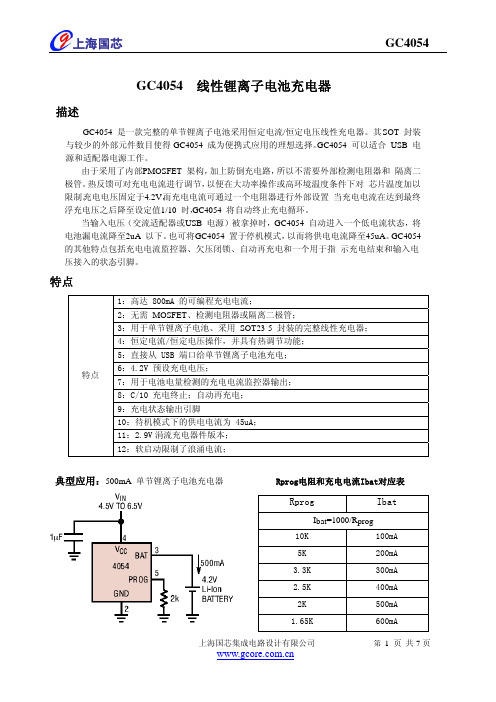
GC4054 线性锂离子电池充电器描述GC4054 是一款完整的单节锂离子电池采用恒定电流/恒定电压线性充电器。
其 S OT 封装与较少的外部元件数目使得 GC4054 成为便携式应用的理想选择。
GC4054 可以适合 USB 电源和适配器电源工作。
由于采用了内部 P MOSFET 架构,加上防倒充电路,所以不需要外部检测电阻器和 隔离二极管。
热反馈可对充电电流进行调节,以便在大功率操作或高环境温度条件下对 芯片温度加以限制。
充电电压固定于 4.2V ,而充电电流可通过一个电阻器进行外部设置 当充电电流在达到最终浮充电压之后降至设定值 1/10 时,GC4054 将自动终止充电循环。
当输入电压(交流适配器或 U SB 电源)被拿掉时,GC4054 自动进入一个低电流状态,将电池漏电流降至 2uA 以下。
也可将 G C4054 置于停机模式,以而将供电电流降至45uA 。
GC4054 的其他特点包括充电电流监控器、欠压闭锁、自动再充电和一个用于指 示充电结束和输入电压接入的状态引脚。
特点特点1:高达 800mA 的可编程充电电流;2:无需 MOSFET 、检测电阻器或隔离二极管;3:用于单节锂离子电池、采用 SOT23-5 封装的完整线性充电器; 4:恒定电流/恒定电压操作,并具有热调节功能; 5:直接从 USB 端口给单节锂离子电池充电;6:4.2V 预设充电电压;7:用于电池电量检测的充电电流监控器输出; 8:C/10 充电终止;自动再充电; 9:充电状态输出引脚10:待机模式下的供电电流为 45uA; 11:2.9V 涓流充电器件版本; 12:软启动限制了浪涌电流;典型应用:500mA 单节锂离子电池充电器 Rprog电阻和充电电流Ibat对应表RprogIbatI bat =1000/R prog 10K 100mA 5K 200mA 3.3K 300mA 2.5K 400mA 2K500mA 1.65K600mA引脚分布引脚功能绝对最大额定值输入电源电压4.5V~6V PROG -0.3V~VCC+0.3VBAT -0.3V~7V CHRG-0.3V~10VBAT 短路持续时间 连续 BAT 引脚电流 800mA PROG 引脚电流800uA 最大结温 145℃ 工作环境温度范围 -20℃~85℃ 贮存温度范围 -65℃~125℃引脚温度(焊接时间10s)260℃CHRG(引脚1)漏极开路充电状态输出。
2022最新USB命名及速率标准
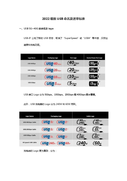
2022最新USB命名及速率标准一、USB 5G~40G的命名及logoUSB-IF公布了新的USB标志,取消了“SuperSpeed”或“USB4”等术语,只标出速度和充电功率。
USB接口Logo分为5Gbps、10Gbps、20Gbps和40Gbps四个等级。
此外,USB充电器的Logo分为240W和60W两种。
充电线的Logo更为复杂,分为:40Gbps/240W、/60W、20Gbps/240W、20Gbps/60W、5Gbps/240W、5Gbps/60W以及240W、60W八种。
USB-IF还公布了USB4 2.0,速度达到80Gbps,该标准落实后也将加入该Logo体系。
二、USB4 2.0新标准,速率高达80Gbps1.发布时间:2022年9月1日,USB-IF官网更新公告,正式发布了了新一代数据接口规范USB4 2.0版本,支持高达80Gbps数据传输速率,超越雷电4。
2.性能特点1)数据速率提升至80Gbps此前发布的USB4 1.0标准是基于雷电3技术上开发而来,最大数据传输速率为40Gbps,而新发布的USB4 2.0版本,基于全新的物理层架构开发,将数据传输速率从40Gbps峰值提升至80Gbps峰值,为USB-C生态系统打造更高性能的天花板。
从中受益的包括8K以上分辨率带扩展坞的高性能显示器、显卡扩展坞、PCI-e 5.0外置存储设备、超高速扩展中心等。
2)数据架构更新,USB3.2也能受惠USB4 2.0数据架构也进行了更新,有利于设备充分合理地利用好带宽,不止让USB4提升带宽翻倍至80Gbps,也影响了USB3.2 、DisplayPort视频传输、PCI Express数据通道。
此前USB3.2最高传输速率为20Gbps(USB3.2 Gen2x2),新数据架构下,USB3.2速率将超越20Gbps,达到更高规格。
数据架构变动已经不是第一次发生,intel主推的雷电3升级至雷电4,两者最大带宽同样都是40Gbps,但雷电3总带宽分配为22Gbps+18Gbps(数据可用带宽+视频可用带宽),而雷电4则变动为32Gbps+8Gbps(数据可用带宽+视频可用带宽),对高速硬盘、显卡扩展坞等严重依赖于数据通道的设备,雷电4的数据可用带宽性能提升有目共睹。
LTC4054

器从改脚引出,控制输出电压。关断模式下,此电阻分压器从改脚断开连接。 VCC(4):电源输入正极。向充电器供电,电压范围 4.5V 至 6.5V。接 1μF 对地电容以减少纹波。 PROG(5):充电电流编程器脚,充电电流监测与充电开关。可通过此脚与地之间链接的 1%电阻来设定
工作范围(2)
2of 6
参数 输入电压
结温
LTC4054
独立线性锂电池充电器
符号
V CC
TJ
数值 -0.3 ~ +10 -40 ~ +80
单位 V °C
直流电学特性
(VCC = 5V, TJ= 25 °C,特别标注除外)
参数
符号 整流输出电压 BAT脚电流 涓流充电电流 涓流隔值电压
4of 6
应用说明
LTC4054
独立线性锂电池充电器
稳定性:
恒流反馈控制环路无需输出电容即可输出稳定的电压给外接在充电器输出端上的电池。如无外接电 池,输出应接一输出电容以 减少纹波。如使用大容量、低ESR的陶瓷电容,则应在电容上串一个1Ω为 佳;如使用钽电容则无需串联电阻。
恒流模式下,PROG脚为反馈环路。恒流模式的稳定性受PROG脚的阻抗影响。如无外加电容于 PROG脚上,则当编程电阻高至20KΩ时,充电器仍能保持稳定;然而,如有外加电容,最大允许编程 电阻将减小。
1of 6
管脚描述
LTC4054
独立线性锂电池充电器
管脚号
1 2 3 4 5
管脚名
CHRG GND BAT VCC PROG
功能
LTC4054充电板调试及测试结果
1LTC4054充电板调试及测试结果
1、充电电路连接
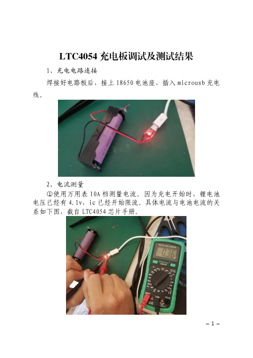
焊接好电路板后,接上18650电池座,插入microusb 充电
线。
2、电流测量
①使用万用表10A 档测量电流。
因为充电开始时,锂电池电压已经有4.1v,ic 已经开始限流。
具体电流与电池电流的关系如下图,截自LTC4054
芯片手册。
2
②使用usb
电流计测量电流
3、充电完成
Led 灯熄灭
3
电池电压为
4.21V
4、结论
以LTC4054为主芯片制作的充电电路板具有体积小、成本低的特点。
充电性能符合预期,能满足一般要求的充电情况。
5、缺点
因该IC 为线性锂电池充电,充电电流较大时芯片温度高,
温度高会导致芯片寿命减少且充电电流变小。
6、改进空间
①增加散热片。
②芯片电源输入端串联一个电阻或者二极管降低芯片上的压差。
可以串联一个1/8W的0.25Ω的电阻,或一个整流二极管如1N4001。
4。
TC4054(0.5A线性锂离子电池充电器 IC)中文技术资料
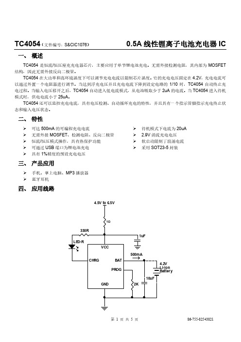
TC4054(文件编号:S&CIC1076)0.5A线性锂离子电池充电器IC一、概述TC4054是恒流/恒压座充充电器芯片,主要应用于单节锂电池充电。
无需外接检测电阻,其内部为MOSFET 结构,因此无需外接反向二极管。
TC4054在大功率和高环境温度下可以调节充电电流以限制芯片温度。
它的充电电压固定在4.2V,充电电流可以通过外置一个电阻器进行调节。
当达到浮充电压并且充电电流下降到设定电路的1/10时,TC4054自动终止充电过程。
当输入电压移开之后,TC4054自动进入低电流模式,从电池吸取少于2uA的电流。
当TC4054进入待机模式时,供电电流小于25uA。
TC4054还可以监控充电电流,具有电压检测、自动循环充电的特性,并且具有一个指示管脚指示充电终止状态和输入电压状态。
二、特性可达500mA的可编程充电电流无需外接MOSFET、检测电阻、反向二极管恒流/恒压模式操作,具有热保护功能可通过USB端口为锂电池充电具有1%精度的预设充电电压待机模式下电流为20uA2.9V涓流充电电压软启动限制了浪涌电流采用SOT23-5封装TC4054(文件编号:S&CIC1076)0.5A线性锂离子电池充电器ICTC4054(文件编号:S&CIC1076)0.5A线性锂离子电池充电器IC 七、电气特性(V=5V;T J=25℃,除非另有说明)IN注:1、超出最大工作范围可能会损坏芯片。
2、超出器件工作参数极限,不保证其正常功能。
3、电源电流包括PROG端电流(大约100uA),不包括通过BAT端传输到电池的其他电流(大约100uA)。
4、充电终止电流一般是设定充电电流的0.1倍。
TC4054(文件编号:S&CIC1076)0.5A线性锂离子电池充电器IC八、波形图浮动电压VS电源电压充电电流VS 电源电压涓流充电电流VS电源电压浮动电压VS 温度TC4054(文件编号:S&CIC1076)0.5A线性锂离子电池充电器IC九、封装尺寸图SOT23-5。
LTC4054 凌特尔芯片-USB 锂电池充电概念阐述
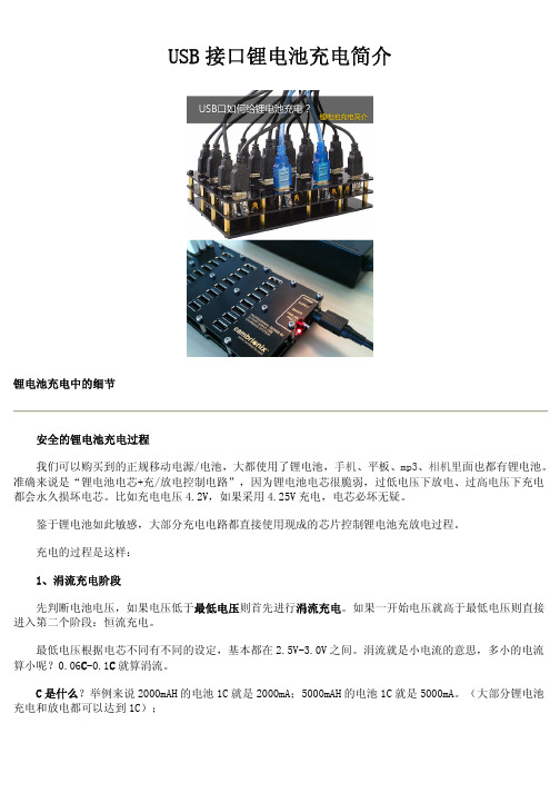
USB接口锂电池充电简介锂电池充电中的细节安全的锂电池充电过程我们可以购买到的正规移动电源/电池,大都使用了锂电池,手机、平板、mp3、相机里面也都有锂电池。
准确来说是“锂电池电芯+充/放电控制电路”,因为锂电池电芯很脆弱,过低电压下放电、过高电压下充电都会永久损坏电芯。
比如充电电压4.2V,如果采用4.25V充电,电芯必坏无疑。
鉴于锂电池如此敏感,大部分充电电路都直接使用现成的芯片控制锂电池充放电过程。
充电的过程是这样:1、涓流充电阶段先判断电池电压,如果电压低于最低电压则首先进行涓流充电。
如果一开始电压就高于最低电压则直接进入第二个阶段:恒流充电。
最低电压根据电芯不同有不同的设定,基本都在2.5V-3.0V之间。
涓流就是小电流的意思,多小的电流算小呢?0.06C-0.1C就算涓流。
C是什么?举例来说2000mAH的电池1C就是2000mA;5000mAH的电池1C就是5000mA。
(大部分锂电池充电和放电都可以达到1C);对于这块电池来说0.1C就是188mA2、恒流充电阶段涓流充电到电池电压高于最小电压后,充电器以恒定电流给电池充电,这个恒定电流就是很多充电器上标注的多少多少安。
比如iPhone4/4S是1A,iPad是2.1A。
恒流充电的过程中,电池电压也在逐渐升高,从最小电压上升到4.2V时恒流充电阶段终止,恒流过程实际能为电池充进40%-70%左右的电量。
之后进入下一个阶段:恒压充电。
3、恒压充电阶段恒定4.2V(±0.35%的精度)给电池充电,这个阶段里电流就不能维持恒定了,而是逐渐下降,当充电电流下降至0.1C后充电过程结束。
这个阶段实际上可以充进60%-30%的电量。
所以一块2000mAH的电池用1000mA的充电器充电时即便没有热损失出现,时间也会大于2小时。
如果把电压转换中产生的废热算上也许实际充满电的时间超过3小时。
上图就是刚才所说的3个过程,所有锂电池充电时都要遵循这个规律,所以现在转而说到USB口给锂电池充电,中间就需要有控制电路和电压转换电路,不然4.5V-5V的电压加在锂电池上,电池直接就损坏了。
长城汽车使用手册说明书
操作
介绍了钥匙、车门、车窗、座椅等车内装备的基本操作方法。
驾驶
介绍了车辆启动、换挡方法、仪表等驾驶相关内容。
视听系统
介绍了蓝牙电话、系统设置等视听系统相关内容。
安全性
介绍了车辆防盗系统、安全带等保护装置。
紧急情况
介绍了爆胎、蓄电池亏电等车辆故障的处理方法。
维护保养
介绍了车辆的日常检查以及定期维护保养的事项。
4
外观 A
B
C
DE
F
G
H
I
J
K
5
Ⓐ 货箱门把手 25 Ⓑ 高位制动灯 Ⓒ 车窗 28 Ⓓ 外后视镜 47 Ⓔ 前雨刮 54 Ⓕ 门锁 22
Ⓖ 倒车影像 93 Ⓗ 后组合灯 49 Ⓘ 充电口 33 Ⓙ 前组合灯 49 Ⓚ 侧转向灯 49
6
内饰
AB
C
D EF G
H
IJK
L MN
QO
7
Ⓐ 中控锁按钮 22 Ⓑ 灯光控制组合开关 49 Ⓒ 组合仪表 120 Ⓓ 雨刮控制组合开关 54 Ⓔ 中控面板开关总成 Ⓕ 换挡杆 87 Ⓖ 空调出风口 61 Ⓗ 车门内扣手 23
〉 谨慎驾驶:务必谨慎驾驶。随时注意路面 上其他驾驶员或行人的错误动向,以便及 时做出判断,防止意外事故的发生。
〉 专注驾驶:驾驶时务必全神贯注。任何分 散驾驶员注意力的事情,如调节控制按 钮、接打手机或阅读都可能引发碰撞事故 并导致您、车上的乘客以及其他人员严重 伤亡。
警告
禁止将儿童单独留在车内,也不要让儿童携 带或使用钥匙。 儿童可能会启动车辆或随意切换换挡杆挡 位。儿童玩耍车窗、天窗或车辆的其他设备 时也可能会伤害到他们自己。此外,车内温 度过高或过低,也可能会对儿童造成致命伤 害。
星辰(StarTech)ICUSB422IS 1端口金属工业USB到RS422 RS485串行适配器

1 Port Metal Industrial USB to RS422/RS485 Serial Adapter w/ IsolationProduct ID: ICUSB422ISThe ICUSB422IS 1 Port Metal Industrial USB to RS422/RS485 Serial Adapter w/ Isolation connects to a computer using USB and allows you to connect any RS-422 or RS-485 serial device via the provided DB9 port or hard-wired to the terminal block.The USB to serial adapter features circuit isolation to ensure that sensitive controls and devices will not be damaged while connected, making it a viable solution for connecting costly industrial serial devices.The RS422/485 Converter receives full power via the host USB connection, and provides power to the attached serial device without requiring an external power adapter. Designed to provide a durable serial solution, the USB to RS422/485 Converter is ruggedly constructed and can be mounted nearly anywhere. Backed by a 2-year warranty and free lifetime technical support.Certifications, Reports and Compatibility Applications•POS (credit/debit card readers, receipt printers, bar code scanners,cash registers, scales)•Manufacturing (CNC machinery, process control equipment, bar code scanners, serial printers)•Hotel Front Desk (serial printers, bar code scanners, keyboard, mouse, receipt printer, credit/debit card reader)•Hospitality/Restaurant (credit card/debit card reader, serial printers)•Hospital (monitoring equipment, nurses' stations)•Security (UPS control, access key panels, video cameras, cardreaders)Features•Provides one RS422/485 port while powering the device through USB •RS-485 mode supports Auto Transceiver Turn Around (ATTA)•Compatible with both USB 2.0 and USB 1.1•RS422/485 Baud rate up to 921.6 Kbps•Supports DB9 and terminal block connector•Optical Isolation and Surge Protection (2500 Vrms)•Supports 4-wire RS422 and 2-wire RS485 applicationsWarranty 2 YearsHardware Bus Type USB 2.0Chipset ID FTDI - FT232RLInterface SerialPort Style External HubPorts1Performance Data Bits7, 8FIFO256 Byte Receive/128 Byte TransmitIsolation2500 VrmsMax Baud Rate921.6 KbpsParity Even, Odd, Mark, Space, NoneSerial Protocol RS-422/485Stop Bits1, 2Surge Protection500WConnector(s)Connector Type(s) 1 - USB B (4 pin) FemaleExternal Ports 1 - DB-9 (9 pin, D-Sub) Male1 - Terminal Block (5 Wire)Software OS Compatibility Windows® CE (4.2, 5.0, 6.0), XP Embedded, 98SE, 2000,XP, Vista, 7, 8, 8.1, 10Windows Server® 2003, 2008 R2, 2012, 2012 R2, 2016,2019Mac OS® 10.6 to 10.15Linux 2.4.x to 4.11.x LTS Versions onlyPower Input Current200mAInput Voltage 5 DCPower Source USB-PoweredEnvironmental Humidity5~95% RHOperating Temperature0°C to 55°C (32°F to 131°F)Storage Temperature-20°C to 85°C (-4°F to 185°F)Cable Length 6 ft [1.8 m]PhysicalCharacteristicsColor BlackMaterial SteelProduct Height0.9 in [2.3 cm]Product Length 4.6 in [11.8 cm]Product Width 2.5 in [64 mm]Weight of Product 6.4 oz [180 g]PackagingPackage Height 6.3 in [16 cm]InformationPackage Length9.1 in [23 cm]Package Width 1.8 in [45 mm]Shipping (Package) Weight0.9 lb [0.4 kg]What's in the Box Included in Package 1 - USB to RS422/485 Converter1 - 6ft USB A to B Cable1 - Driver CD1 - User ManualProduct appearance and specifications are subject to change without notice.。
TC4056原厂

4.16 450 950 0
120 2.8 60 3.5 150 60 5 60 120 0.9
43
100
4.2 500 1000 -2.5 ±1 -1 130 2.9 80 3.7 200 100 30 70 130 1.0 0.3
4.24 550 1050 -6 ±2 -2 140 3.0 100 3.9 300 100 30 80 140 1.1 0.6
VBAT 高至低 IBAT 降至 ICHG/10 以下
1A 线性锂离子电池充电器
0.8
1.8
4
ms
0.8
1.8
ms
2.0
μA
八、典型性能特征
恒定电流模式下 PROG 引脚 电压与电源电压的关系曲线
PROG 引脚电压与温度的 关系曲线
充电电流与 PROG 引脚电 压的关系曲线
稳定输出(浮充)电压与充 电电流的关系曲线
电流小于 2uA。BAT 管脚向电池提供充电电流和 4.2V 的限制电压。 CE(引脚 8)芯片始能输入端。高输入电平将使 TC4056 处于正常工作状态;低输入电平使 TC4056 处于被
禁止充电状态。CE 管脚可以被 TTL 电平或者 CMOS 电平驱动。
第 2 页 共 15 页
TC4056
状态下,BAT 引脚上的所有负载都必须由电池来供电。在待机模式中,TC4056 对BAT引脚电压进行连续监控。
如果该引脚电压降到4.05V 的再充电电门限( RECHRG V )以下,则另一个充电循环开始并再次向电池供应电流。
图 1 示出了一个典型充电循环的状态图。
热限制
如果芯片温度升至约140℃的预设值以上,则一个内部热反馈环路将减小设定的充电电流,直到150℃以上减小电 流至0。该功能可防止TC4056过热,并允许用户提高给定电路板功率处理能力的上限而没有损坏TC4056 的风险。 在保证充电器将在最坏情况条件下自动减小电流的前提下,可根据典型(而不是最坏情况)环境温度来设定充电电 流。
TC40电池充电器说明书

Battery Charger TC40 Owner’s Manual© Dolgin Engineering 1019 Massachusetts Ave. Lexington, MA 02420 • (781) 863-1813 • 1 IntroductionThe TC40 Battery Charger is electrically compatible with all 7.2V Li-Ion camera batteries rated 2200 mAh or higher. The modular design allows for different battery models to be charged when the appropriate adapter plate is fitted. With the appropriate power cord, the charger can be powered by a 12V automobile power source.Standard Features• Four simultaneous charge positions for fast charging of 4 batteries.• Fast, safe, and reliable charging. The battery pack can be left on the charger after the charge is complete. • Dynamic Power Management (DPM) minimizes battery charge time. By dynamically adjusting battery charge current, more current is allocated to the deeper discharged battery. Through this process allbatteries are ready to use at about the same time.• Wide range input power compatibility (100-240VAC 50-60Hz), 12V with the DC cigarette lighter cord. • Compact, lightweight design for easy portability. Dimensions 10.5"x 4"x 1.5"BatteriesThe charger is capable of charging 4 batteries at the same time. It accepts Sony L/M (VX2xx or similar), Panasonic DVX100, Canon BPxx (XL/GL), and JVC BNVxx style batteries. The charger must be configured with the appropriate plate to match the battery style.The battery must to be rated at least 2200 mah capacity , as smaller size battery packs are not designed to accept the charger fast charge.Charging timeThe time to full charge depends on the battery pack rated capacity, its state of charge prior to insertion, and its age. A fully discharged new 2200 mAh battery will be fully charged (more than 90%) in about 2.5 hours. A 5600 mAh pack will take approximately 3.5 - 4 hours to charge (4.5 -5 hours when 2 batteries in the same bank* are being charged). Since a depleted battery pack absorbs charge current faster, than a partially charged one, most of the charge energy is absorbed during the initial stage of charging and then the rate of charge levels off towards the end.Charge channelsLEDs indicate each battery’s state of charge. Dynamic Power Management (DPM) minimizes battery charge time. By dynamically adjusting battery charge current, more current is allocated to the deeper discharged of the two batteries (in the same bank). Through this process both batteries are ready to use at about the same timeOperationChargingUpon plugging the charger in into an electrical source the green and red LEDs will blink every 3 seconds to indicate the charger is powered on. Insert a battery into the battery plate and the charger will initiate the charge routine. While charging is in progress, the red LED will illuminate. Approaching charge completion, the Green LED will blink at 90% readiness level, and will be steady ON on completion.Status LEDs1. Red ON Battery is inserted; charge in progress2. Green blinking Battery is charged over 90%3. Green ON Ready* Charging positions are grouped in 2 banks of 2 plates. In order to get the fastest charge time, when charging 2 batteries, place them in positions 1, 3.。
- 1、下载文档前请自行甄别文档内容的完整性,平台不提供额外的编辑、内容补充、找答案等附加服务。
- 2、"仅部分预览"的文档,不可在线预览部分如存在完整性等问题,可反馈申请退款(可完整预览的文档不适用该条件!)。
- 3、如文档侵犯您的权益,请联系客服反馈,我们会尽快为您处理(人工客服工作时间:9:00-18:30)。
PROG CHRGT VCC
VDD NC NC VBAT
SOT23-6 功能说明 充电指示脚
地 充电电流输出脚
名称 PROG CHRGT VCC
1
8
CHRGT
2
7
PROG
3
6
CHRG
4
5
GND
SOP-8
功能说明 充电电流预设脚 充电完成指示脚
电源脚
Page 1 of 6
深圳市金道微电子有限公司
SHENZHEN KINGDAU ELECTRONICS CO., LTD.
℃/W mA uA ℃ ℃ ℃ ℃
Page 2 of 6
深圳市金道微电子有限公司
SHENZHEN KINGDAU ELECTRONICS CO., LTD.
TC4054(文件编号:S&CIC0874)
USB 充电器 IC
七、 电气特性 (VIN=5V; TJ=25℃; 除特殊说明.)
符号
参数
条件
最小值 典型值 最大值 单位
TC4054 也提供了片内温度保护。当温度达到预定的水平且电池面临过热危险,TC4054 将减少充电电流使温度逐 渐降低。为电池充电提供适当的保护。
二、 特点
¾ 充电电流最大可调整到800mA。 ¾ 不需要外接MOSFET、电阻或阻塞二极管。 ¾ 带热保护的恒流/恒压操作最大限度保证充电速度
而无过热的危险。 ¾ 直接从USB接口为单节锂电池充电。 ¾ VBAT端输出预设充电电压4.2V,±1%的精度。 ¾ 集成完整的充电状态显示功能,简化外围电路。
+/-5
uA
ITRIKL
涓流充电电流
VBAT < VTRIKL, RPROG = 10k
15
mA
VTRIKL
涓流充电阈值电压
RPROG = 10k, VBAT Rising
2.8
2.9
Байду номын сангаас3.0
V
VUV
VCC欠电压锁定阈值 From VCC Low to High
3.4
V
VUVHYS
VCC欠压锁定滞后
100
VCC
输入电源电压
充电模式(3), RPROG = 10k
4.25
6.5
V
110
500
uA
ICC
芯片消耗电流
低功耗模式(充电完成)
关断模式(RPROG Not Connected, VCC < VBAT, or VCC < VUV)
70
uA
35
50
uA
VFLOAT
预设充饱电压
VCC=5V RPROG = 10k, Current Mode
符号 VCC VIN VPROG VBAT VCHRG
θJA IBAT IPROG TJ TJ TS
额定值 7
-0.3 to 7 VCC+0.3
7 7 Continuous 连续 75 (DIP/SOP8) 800 800 125 -40 to 85 -65 to 125 300
单位 V V V V V
SHENZHEN KINGDAU ELECTRONICS CO., LTD.
TC4054(文件编号:S&CIC0874)
USB 充电器 IC
3、芯片的工作电流包括PROG Pin外面电阻消耗的电流(约100uA),但不包括芯片通过BAT Pin给芯片充电的 电流(约100mA)。
4、充电终止电流一般是设定充电电流的0.1倍。
八、 功能方框图
VCC
m=1
m=1000
OTP BAT
UVLO
LED_G LED_R
+ -
+ -
+ -
Shut Down
+
- Vref
V re f
CHRG CHRGT
Control
Chrg-T
Trickle
VCC
Auto Recharge
PROG
Rprog
GND
Page 4 of 6
深圳市金道微电子有限公司
150
mV
TLIM
过温关断点
tSS tTERM
软启动时间
恒流充电到涓流充电 的转换时间
IBAT = 0 to 1000V/RPROG
IPROG
PROG上拉电流
注:1、超出最大工作范围可能会损坏芯片。 2、芯片不建议工作在极限参数的状态下。
120
℃
100
us
1000
us
1
uA
Page 3 of 6
深圳市金道微电子有限公司
TC4054(文件编号:S&CIC0874)
USB 充电器 IC
五、 应用电路图
LED-G
330R 4.5V to 6.5V
LED-R
V CC
CHRG CHRGT
BAT PROG
1uF
→ 600mA
4.2V Li-lon Batt er y
GND
1.65K
六、 绝对最大额定值 (1)
参数 输入电源电压 输入电压 PROG 电压 BAT 电压 CHRG 电压 BAT 短路 热阻 BAT 电流 PROG 电流 最高结温 内部结温 贮藏温度 焊接温度(不超过10sec)
mV
VMSD
手动关断阈值电压
PROG Pin 上升 PROG Pin 下降
1.25
V
1.2
V
VASD
VCC充电阈值电压
VCC 从低到高 VCC 从高到低
100
mV
30
mV
VPROG
充电基准电压
RPROG = 10k, Current Mode
0.9
1.03
1.1
V
△VRECHRG 自动重充迟滞电压
VFLOAT - VRECHRG
4.20
4.25
4.30
V
90
100
130
mA
BAT 电流
IBAT
充电电流
RPROG = 2k, Current Mode
500
mA
低功耗模式, VBAT = 4.2V
0
+/-1
+/-5
uA
关断模式 (RPROG Not Connected)
+/-0.5 +/-5
uA
睡眠模式, VCC = 0V
+/-1
USB 充电器 IC
SOP-8
Page 6 of 6
深圳市金道微电子有限公司
SHENZHEN KINGDAU ELECTRONICS CO., LTD.
TC4054(文件编号:S&CIC0874)
USB 充电器 IC
一、 概述
TC4054 是一款管理锂电池充电功能的完整系统集成电路,它能提供快速充电,并最大化地延长电池寿命。TC4054 监测电池的情况,如果电池电压低于 2.9V 时,决定是否需要预充电。预充电电流可通过外部电阻在 7.5mA 到 120mA 的任意范围内设置。预充电状态会使电池保持良好状况,并延长电池寿命。一旦电池电压达 2.9V,TC4054 将自动转 换为恒流(CC)充电周期。内部电流的设定为预充电时电流的 6 倍以上。恒流循环功能将需要充电的时间降到最短,当 电池接近完全饱和,大概在 4.15V 左右,TC4054 将自动转换为恒压(CV)的充电周期。在恒压充电周期,充电电流将 会减小使电池逐渐饱和而没有过饱和的危险,这是必要的,因为锂电池不能过饱和 50mV,否则就有爆炸的危险。 TC4054 确保锂电充满,但不会进入过饱和状态。在充电完成后,TC4054 将进入关闭模式,降低内部耗电量到小于 35uA。这一特点使 TC4054 能够应用到便携式设备的内部,并在设备不工作时几乎不消耗任何能量。
SHENZHEN KINGDAU ELECTRONICS CO., LTD.
TC4054(文件编号:S&CIC0874)
USB 充电器 IC
九、 封装尺寸图 SOT23-6
Page 5 of 6
深圳市金道微电子有限公司
SHENZHEN KINGDAU ELECTRONICS CO., LTD.
TC4054(文件编号:S&CIC0874)
三、 产品应用
¾ 手机、MP3、掌上电脑;
¾ 2.9V的涓流充电门限。 ¾ 关断模式下供电电流为35uA。 ¾ 具有过热保护功能。 ¾ 可抗2KV以上ESD。 ¾ 采用SOT23-6(TC4054),SOP-8(TC4054S)封装形
式。
四、 管脚图及功能说明
名称 CHRG GND BAT
CHRG GND BAT
