037Design-01
NuMicro N9H30系列开发板用户手册说明书

NuMicro®FamilyArm® ARM926EJ-S BasedNuMaker-HMI-N9H30User ManualEvaluation Board for NuMicro® N9H30 SeriesNUMAKER-HMI-N9H30 USER MANUALThe information described in this document is the exclusive intellectual property ofNuvoton Technology Corporation and shall not be reproduced without permission from Nuvoton.Nuvoton is providing this document only for reference purposes of NuMicro microcontroller andmicroprocessor based system design. Nuvoton assumes no responsibility for errors or omissions.All data and specifications are subject to change without notice.For additional information or questions, please contact: Nuvoton Technology Corporation.Table of Contents1OVERVIEW (5)1.1Features (7)1.1.1NuMaker-N9H30 Main Board Features (7)1.1.2NuDesign-TFT-LCD7 Extension Board Features (7)1.2Supporting Resources (8)2NUMAKER-HMI-N9H30 HARDWARE CONFIGURATION (9)2.1NuMaker-N9H30 Board - Front View (9)2.2NuMaker-N9H30 Board - Rear View (14)2.3NuDesign-TFT-LCD7 - Front View (20)2.4NuDesign-TFT-LCD7 - Rear View (21)2.5NuMaker-N9H30 and NuDesign-TFT-LCD7 PCB Placement (22)3NUMAKER-N9H30 AND NUDESIGN-TFT-LCD7 SCHEMATICS (24)3.1NuMaker-N9H30 - GPIO List Circuit (24)3.2NuMaker-N9H30 - System Block Circuit (25)3.3NuMaker-N9H30 - Power Circuit (26)3.4NuMaker-N9H30 - N9H30F61IEC Circuit (27)3.5NuMaker-N9H30 - Setting, ICE, RS-232_0, Key Circuit (28)NUMAKER-HMI-N9H30 USER MANUAL3.6NuMaker-N9H30 - Memory Circuit (29)3.7NuMaker-N9H30 - I2S, I2C_0, RS-485_6 Circuit (30)3.8NuMaker-N9H30 - RS-232_2 Circuit (31)3.9NuMaker-N9H30 - LCD Circuit (32)3.10NuMaker-N9H30 - CMOS Sensor, I2C_1, CAN_0 Circuit (33)3.11NuMaker-N9H30 - RMII_0_PF Circuit (34)3.12NuMaker-N9H30 - RMII_1_PE Circuit (35)3.13NuMaker-N9H30 - USB Circuit (36)3.14NuDesign-TFT-LCD7 - TFT-LCD7 Circuit (37)4REVISION HISTORY (38)List of FiguresFigure 1-1 Front View of NuMaker-HMI-N9H30 Evaluation Board (5)Figure 1-2 Rear View of NuMaker-HMI-N9H30 Evaluation Board (6)Figure 2-1 Front View of NuMaker-N9H30 Board (9)Figure 2-2 Rear View of NuMaker-N9H30 Board (14)Figure 2-3 Front View of NuDesign-TFT-LCD7 Board (20)Figure 2-4 Rear View of NuDesign-TFT-LCD7 Board (21)Figure 2-5 Front View of NuMaker-N9H30 PCB Placement (22)Figure 2-6 Rear View of NuMaker-N9H30 PCB Placement (22)Figure 2-7 Front View of NuDesign-TFT-LCD7 PCB Placement (23)Figure 2-8 Rear View of NuDesign-TFT-LCD7 PCB Placement (23)Figure 3-1 GPIO List Circuit (24)Figure 3-2 System Block Circuit (25)Figure 3-3 Power Circuit (26)Figure 3-4 N9H30F61IEC Circuit (27)Figure 3-5 Setting, ICE, RS-232_0, Key Circuit (28)Figure 3-6 Memory Circuit (29)Figure 3-7 I2S, I2C_0, RS-486_6 Circuit (30)Figure 3-8 RS-232_2 Circuit (31)Figure 3-9 LCD Circuit (32)NUMAKER-HMI-N9H30 USER MANUAL Figure 3-10 CMOS Sensor, I2C_1, CAN_0 Circuit (33)Figure 3-11 RMII_0_PF Circuit (34)Figure 3-12 RMII_1_PE Circuit (35)Figure 3-13 USB Circuit (36)Figure 3-14 TFT-LCD7 Circuit (37)List of TablesTable 2-1 LCD Panel Combination Connector (CON8) Pin Function (11)Table 2-2 Three Sets of Indication LED Functions (12)Table 2-3 Six Sets of User SW, Key Matrix Functions (12)Table 2-4 CMOS Sensor Connector (CON10) Function (13)Table 2-5 JTAG ICE Interface (J2) Function (14)Table 2-6 Expand Port (CON7) Function (16)Table 2-7 UART0 (J3) Function (16)Table 2-8 UART2 (J6) Function (16)Table 2-9 RS-485_6 (SW6~8) Function (17)Table 2-10 Power on Setting (SW4) Function (17)Table 2-11 Power on Setting (S2) Function (17)Table 2-12 Power on Setting (S3) Function (17)Table 2-13 Power on Setting (S4) Function (17)Table 2-14 Power on Setting (S5) Function (17)Table 2-15 Power on Setting (S7/S6) Function (18)Table 2-16 Power on Setting (S9/S8) Function (18)Table 2-17 CMOS Sensor Connector (CON9) Function (19)Table 2-18 CAN_0 (SW9~10) Function (19)NUMAKER-HMI-N9H30 USER MANUAL1 OVERVIEWThe NuMaker-HMI-N9H30 is an evaluation board for GUI application development. The NuMaker-HMI-N9H30 consists of two parts: a NuMaker-N9H30 main board and a NuDesign-TFT-LCD7 extensionboard. The NuMaker-HMI-N9H30 is designed for project evaluation, prototype development andvalidation with HMI (Human Machine Interface) function.The NuMaker-HMI-N9H30 integrates touchscreen display, voice input/output, rich serial port serviceand I/O interface, providing multiple external storage methods.The NuDesign-TFT-LCD7 can be plugged into the main board via the DIN_32x2 extension connector.The NuDesign-TFT-LCD7 includes one 7” LCD which the resolution is 800x480 with RGB-24bits andembedded the 4-wires resistive type touch panel.Figure 1-1 Front View of NuMaker-HMI-N9H30 Evaluation BoardNUMAKER-HMI-N9H30 USER MANUAL Figure 1-2 Rear View of NuMaker-HMI-N9H30 Evaluation Board1.1 Features1.1.1 NuMaker-N9H30 Main Board Features●N9H30F61IEC chip: LQFP216 pin MCP package with DDR (64 MB)●SPI Flash using W25Q256JVEQ (32 MB) booting with quad mode or storage memory●NAND Flash using W29N01HVSINA (128 MB) booting or storage memory●One Micro-SD/TF card slot served either as a SD memory card for data storage or SDIO(Wi-Fi) device●Two sets of COM ports:–One DB9 RS-232 port with UART_0 used 75C3232E transceiver chip can be servedfor function debug and system development.–One DB9 RS-232 port with UART_2 used 75C3232E transceiver chip for userapplication●22 GPIO expansion ports, including seven sets of UART functions●JTAG interface provided for software development●Microphone input and Earphone/Speaker output with 24-bit stereo audio codec(NAU88C22) for I2S interfaces●Six sets of user-configurable push button keys●Three sets of LEDs for status indication●Provides SN65HVD230 transceiver chip for CAN bus communication●Provides MAX3485 transceiver chip for RS-485 device connection●One buzzer device for program applicationNUMAKER-HMI-N9H30 USER MANUAL●Two sets of RJ45 ports with Ethernet 10/100 Mbps MAC used IP101GR PHY chip●USB_0 that can be used as Device/HOST and USB_1 that can be used as HOSTsupports pen drives, keyboards, mouse and printers●Provides over-voltage and over current protection used APL3211A chip●Retain RTC battery socket for CR2032 type and ADC0 detect battery voltage●System power could be supplied by DC-5V adaptor or USB VBUS1.1.2 NuDesign-TFT-LCD7 Extension Board Features●7” resolution 800x480 4-wire resistive touch panel for 24-bits RGB888 interface●DIN_32x2 extension connector1.2 Supporting ResourcesFor sample codes and introduction about NuMaker-N9H30, please refer to N9H30 BSP:https:///products/gui-solution/gui-platform/numaker-hmi-n9h30/?group=Software&tab=2Visit NuForum for further discussion about the NuMaker-HMI-N9H30:/viewforum.php?f=31 NUMAKER-HMI-N9H30 USER MANUALNUMAKER-HMI-N9H30 USER MANUAL2 NUMAKER-HMI-N9H30 HARDWARE CONFIGURATION2.1 NuMaker-N9H30 Board - Front View Combination Connector (CON8)6 set User SWs (K1~6)3set Indication LEDs (LED1~3)Power Supply Switch (SW_POWER1)Audio Codec(U10)Microphone(M1)NAND Flash(U9)RS-232 Transceiver(U6, U12)RS-485 Transceiver(U11)CAN Transceiver (U13)Figure 2-1 Front View of NuMaker-N9H30 BoardFigure 2-1 shows the main components and connectors from the front side of NuMaker-N9H30 board. The following lists components and connectors from the front view:NuMaker-N9H30 board and NuDesign-TFT-LCD7 board combination connector (CON8). This panel connector supports 4-/5-wire resistive touch or capacitance touch panel for 24-bits RGB888 interface.Connector GPIO pin of N9H30 FunctionCON8.1 - Power 3.3VCON8.2 - Power 3.3VCON8.3 GPD7 LCD_CSCON8.4 GPH3 LCD_BLENCON8.5 GPG9 LCD_DENCON8.7 GPG7 LCD_HSYNCCON8.8 GPG6 LCD_CLKCON8.9 GPD15 LCD_D23(R7)CON8.10 GPD14 LCD_D22(R6)CON8.11 GPD13 LCD_D21(R5)CON8.12 GPD12 LCD_D20(R4)CON8.13 GPD11 LCD_D19(R3)CON8.14 GPD10 LCD_D18(R2)CON8.15 GPD9 LCD_D17(R1)CON8.16 GPD8 LCD_D16(R0)CON8.17 GPA15 LCD_D15(G7)CON8.18 GPA14 LCD_D14(G6)CON8.19 GPA13 LCD_D13(G5)CON8.20 GPA12 LCD_D12(G4)CON8.21 GPA11 LCD_D11(G3)CON8.22 GPA10 LCD_D10(G2)CON8.23 GPA9 LCD_D9(G1) NUMAKER-HMI-N9H30 USER MANUALCON8.24 GPA8 LCD_D8(G0)CON8.25 GPA7 LCD_D7(B7)CON8.26 GPA6 LCD_D6(B6)CON8.27 GPA5 LCD_D5(B5)CON8.28 GPA4 LCD_D4(B4)CON8.29 GPA3 LCD_D3(B3)CON8.30 GPA2 LCD_D2(B2)CON8.31 GPA1 LCD_D1(B1)CON8.32 GPA0 LCD_D0(B0)CON8.33 - -CON8.34 - -CON8.35 - -CON8.36 - -CON8.37 GPB2 LCD_PWMCON8.39 - VSSCON8.40 - VSSCON8.41 ADC7 XPCON8.42 ADC3 VsenCON8.43 ADC6 XMCON8.44 ADC4 YMCON8.45 - -CON8.46 ADC5 YPCON8.47 - VSSCON8.48 - VSSCON8.49 GPG0 I2C0_CCON8.50 GPG1 I2C0_DCON8.51 GPG5 TOUCH_INTCON8.52 - -CON8.53 - -CON8.54 - -CON8.55 - -NUMAKER-HMI-N9H30 USER MANUAL CON8.56 - -CON8.57 - -CON8.58 - -CON8.59 - VSSCON8.60 - VSSCON8.61 - -CON8.62 - -CON8.63 - Power 5VCON8.64 - Power 5VTable 2-1 LCD Panel Combination Connector (CON8) Pin Function●Power supply switch (SW_POWER1): System will be powered on if the SW_POWER1button is pressed●Three sets of indication LEDs:LED Color DescriptionsLED1 Red The system power will beterminated and LED1 lightingwhen the input voltage exceeds5.7V or the current exceeds 2A.LED2 Green Power normal state.LED3 Green Controlled by GPH2 pin Table 2-2 Three Sets of Indication LED Functions●Six sets of user SW, Key Matrix for user definitionKey GPIO pin of N9H30 FunctionK1 GPF10 Row0 GPB4 Col0K2 GPF10 Row0 GPB5 Col1K3 GPE15 Row1 GPB4 Col0K4 GPE15 Row1 GPB5 Col1K5 GPE14 Row2 GPB4 Col0K6GPE14 Row2GPB5 Col1 Table 2-3 Six Sets of User SW, Key Matrix Functions●NAND Flash (128 MB) with Winbond W29N01HVS1NA (U9)●Microphone (M1): Through Nuvoton NAU88C22 chip sound input●Audio CODEC chip (U10): Nuvoton NAU88C22 chip connected to N9H30 using I2Sinterface–SW6/SW7/SW8: 1-2 short for RS-485_6 function and connected to 2P terminal (CON5and J5)–SW6/SW7/SW8: 2-3 short for I2S function and connected to NAU88C22 (U10).●CMOS Sensor connector (CON10, SW9~10)–SW9~10: 1-2 short for CAN_0 function and connected to 2P terminal (CON11)–SW9~10: 2-3 short for CMOS sensor function and connected to CMOS sensorconnector (CON10)Connector GPIO pin of N9H30 FunctionCON10.1 - VSSCON10.2 - VSSNUMAKER-HMI-N9H30 USER MANUALCON10.3 - Power 3.3VCON10.4 - Power 3.3VCON10.5 - -CON10.6 - -CON10.7 GPI4 S_PCLKCON10.8 GPI3 S_CLKCON10.9 GPI8 S_D0CON10.10 GPI9 S_D1CON10.11 GPI10 S_D2CON10.12 GPI11 S_D3CON10.13 GPI12 S_D4CON10.14 GPI13 S_D5CON10.15 GPI14 S_D6CON10.16 GPI15 S_D7CON10.17 GPI6 S_VSYNCCON10.18 GPI5 S_HSYNCCON10.19 GPI0 S_PWDNNUMAKER-HMI-N9H30 USER MANUAL CON10.20 GPI7 S_nRSTCON10.21 GPG2 I2C1_CCON10.22 GPG3 I2C1_DCON10.23 - VSSCON10.24 - VSSTable 2-4 CMOS Sensor Connector (CON10) FunctionNUMAKER-HMI-N9H30 USER MANUAL2.2NuMaker-N9H30 Board - Rear View5V In (CON1)RS-232 DB9 (CON2,CON6)Expand Port (CON7)Speaker Output (J4)Earphone Output (CON4)Buzzer (BZ1)System ResetSW (SW5)SPI Flash (U7,U8)JTAG ICE (J2)Power ProtectionIC (U1)N9H30F61IEC (U5)Micro SD Slot (CON3)RJ45 (CON12, CON13)USB1 HOST (CON15)USB0 Device/Host (CON14)CAN_0 Terminal (CON11)CMOS Sensor Connector (CON9)Power On Setting(SW4, S2~S9)RS-485_6 Terminal (CON5)RTC Battery(BT1)RMII PHY (U14,U16)Figure 2-2 Rear View of NuMaker-N9H30 BoardFigure 2-2 shows the main components and connectors from the rear side of NuMaker-N9H30 board. The following lists components and connectors from the rear view:● +5V In (CON1): Power adaptor 5V input ●JTAG ICE interface (J2) ConnectorGPIO pin of N9H30Function J2.1 - Power 3.3V J2.2 GPJ4 nTRST J2.3 GPJ2 TDI J2.4 GPJ1 TMS J2.5 GPJ0 TCK J2.6 - VSS J2.7 GPJ3 TD0 J2.8-RESETTable 2-5 JTAG ICE Interface (J2) Function●SPI Flash (32 MB) with Winbond W25Q256JVEQ (U7); only one (U7 or U8) SPI Flashcan be used●System Reset (SW5): System will be reset if the SW5 button is pressed●Buzzer (BZ1): Control by GPB3 pin of N9H30●Speaker output (J4): Through the NAU88C22 chip sound output●Earphone output (CON4): Through the NAU88C22 chip sound output●Expand port for user use (CON7):Connector GPIO pin of N9H30 FunctionCON7.1 - Power 3.3VCON7.2 - Power 3.3VCON7.3 GPE12 UART3_TXDCON7.4 GPH4 UART1_TXDCON7.5 GPE13 UART3_RXDCON7.6 GPH5 UART1_RXDCON7.7 GPB0 UART5_TXDCON7.8 GPH6 UART1_RTSCON7.9 GPB1 UART5_RXDCON7.10 GPH7 UART1_CTSCON7.11 GPI1 UART7_TXDNUMAKER-HMI-N9H30 USER MANUAL CON7.12 GPH8 UART4_TXDCON7.13 GPI2 UART7_RXDCON7.14 GPH9 UART4_RXDCON7.15 - -CON7.16 GPH10 UART4_RTSCON7.17 - -CON7.18 GPH11 UART4_CTSCON7.19 - VSSCON7.20 - VSSCON7.21 GPB12 UART10_TXDCON7.22 GPH12 UART8_TXDCON7.23 GPB13 UART10_RXDCON7.24 GPH13 UART8_RXDCON7.25 GPB14 UART10_RTSCON7.26 GPH14 UART8_RTSCON7.27 GPB15 UART10_CTSCON7.28 GPH15 UART8_CTSCON7.29 - Power 5VCON7.30 - Power 5VTable 2-6 Expand Port (CON7) Function●UART0 selection (CON2, J3):–RS-232_0 function and connected to DB9 female (CON2) for debug message output.–GPE0/GPE1 connected to 2P terminal (J3).Connector GPIO pin of N9H30 Function J3.1 GPE1 UART0_RXDJ3.2 GPE0 UART0_TXDTable 2-7 UART0 (J3) Function●UART2 selection (CON6, J6):–RS-232_2 function and connected to DB9 female (CON6) for debug message output –GPF11~14 connected to 4P terminal (J6)Connector GPIO pin of N9H30 Function J6.1 GPF11 UART2_TXDJ6.2 GPF12 UART2_RXDJ6.3 GPF13 UART2_RTSJ6.4 GPF14 UART2_CTSTable 2-8 UART2 (J6) Function●RS-485_6 selection (CON5, J5, SW6~8):–SW6~8: 1-2 short for RS-485_6 function and connected to 2P terminal (CON5 and J5) –SW6~8: 2-3 short for I2S function and connected to NAU88C22 (U10)Connector GPIO pin of N9H30 FunctionSW6:1-2 shortGPG11 RS-485_6_DISW6:2-3 short I2S_DOSW7:1-2 shortGPG12 RS-485_6_ROSW7:2-3 short I2S_DISW8:1-2 shortGPG13 RS-485_6_ENBSW8:2-3 short I2S_BCLKNUMAKER-HMI-N9H30 USER MANUALTable 2-9 RS-485_6 (SW6~8) FunctionPower on setting (SW4, S2~9).SW State FunctionSW4.2/SW4.1 ON/ON Boot from USB SW4.2/SW4.1 ON/OFF Boot from eMMC SW4.2/SW4.1 OFF/ON Boot from NAND Flash SW4.2/SW4.1 OFF/OFF Boot from SPI Flash Table 2-10 Power on Setting (SW4) FunctionSW State FunctionS2 Short System clock from 12MHzcrystalS2 Open System clock from UPLL output Table 2-11 Power on Setting (S2) FunctionSW State FunctionS3 Short Watchdog Timer OFFS3 Open Watchdog Timer ON Table 2-12 Power on Setting (S3) FunctionSW State FunctionS4 Short GPJ[4:0] used as GPIO pinS4Open GPJ[4:0] used as JTAG ICEinterfaceTable 2-13 Power on Setting (S4) FunctionSW State FunctionS5 Short UART0 debug message ONS5 Open UART0 debug message OFFTable 2-14 Power on Setting (S5) FunctionSW State FunctionS7/S6 Short/Short NAND Flash page size 2KBS7/S6 Short/Open NAND Flash page size 4KBS7/S6 Open/Short NAND Flash page size 8KBNUMAKER-HMI-N9H30 USER MANUALS7/S6 Open/Open IgnoreTable 2-15 Power on Setting (S7/S6) FunctionSW State FunctionS9/S8 Short/Short NAND Flash ECC type BCH T12S9/S8 Short/Open NAND Flash ECC type BCH T15S9/S8 Open/Short NAND Flash ECC type BCH T24S9/S8 Open/Open IgnoreTable 2-16 Power on Setting (S9/S8) FunctionCMOS Sensor connector (CON9, SW9~10)–SW9~10: 1-2 short for CAN_0 function and connected to 2P terminal (CON11).–SW9~10: 2-3 short for CMOS sensor function and connected to CMOS sensorconnector (CON9).Connector GPIO pin of N9H30 FunctionCON9.1 - VSSCON9.2 - VSSCON9.3 - Power 3.3VCON9.4 - Power 3.3V NUMAKER-HMI-N9H30 USER MANUALCON9.5 - -CON9.6 - -CON9.7 GPI4 S_PCLKCON9.8 GPI3 S_CLKCON9.9 GPI8 S_D0CON9.10 GPI9 S_D1CON9.11 GPI10 S_D2CON9.12 GPI11 S_D3CON9.13 GPI12 S_D4CON9.14 GPI13 S_D5CON9.15 GPI14 S_D6CON9.16 GPI15 S_D7CON9.17 GPI6 S_VSYNCCON9.18 GPI5 S_HSYNCCON9.19 GPI0 S_PWDNCON9.20 GPI7 S_nRSTCON9.21 GPG2 I2C1_CCON9.22 GPG3 I2C1_DCON9.23 - VSSCON9.24 - VSSTable 2-17 CMOS Sensor Connector (CON9) Function●CAN_0 Selection (CON11, SW9~10):–SW9~10: 1-2 short for CAN_0 function and connected to 2P terminal (CON11) –SW9~10: 2-3 short for CMOS sensor function and connected to CMOS sensor connector (CON9, CON10)SW GPIO pin of N9H30 FunctionSW9:1-2 shortGPI3 CAN_0_RXDSW9:2-3 short S_CLKSW10:1-2 shortGPI4 CAN_0_TXDSW10:2-3 short S_PCLKTable 2-18 CAN_0 (SW9~10) Function●USB0 Device/HOST Micro-AB connector (CON14), where CON14 pin4 ID=1 is Device,ID=0 is HOST●USB1 for USB HOST with Type-A connector (CON15)●RJ45_0 connector with LED indicator (CON12), RMII PHY with IP101GR (U14)●RJ45_1 connector with LED indicator (CON13), RMII PHY with IP101GR (U16)●Micro-SD/TF card slot (CON3)●SOC CPU: Nuvoton N9H30F61IEC (U5)●Battery power for RTC 3.3V powered (BT1, J1), can detect voltage by ADC0●RTC power has 3 sources:–Share with 3.3V I/O power–Battery socket for CR2032 (BT1)–External connector (J1)●Board version 2.1NUMAKER-HMI-N9H30 USER MANUAL2.3 NuDesign-TFT-LCD7 -Front ViewFigure 2-3 Front View of NuDesign-TFT-LCD7 BoardFigure 2-3 shows the main components and connectors from the Front side of NuDesign-TFT-LCD7board.7” resolution 800x480 4-W resistive touch panel for 24-bits RGB888 interface2.4 NuDesign-TFT-LCD7 -Rear ViewFigure 2-4 Rear View of NuDesign-TFT-LCD7 BoardFigure 2-4 shows the main components and connectors from the rear side of NuDesign-TFT-LCD7board.NuMaker-N9H30 and NuDesign-TFT-LCD7 combination connector (CON1).NUMAKER-HMI-N9H30 USER MANUAL 2.5 NuMaker-N9H30 and NuDesign-TFT-LCD7 PCB PlacementFigure 2-5 Front View of NuMaker-N9H30 PCB PlacementFigure 2-6 Rear View of NuMaker-N9H30 PCB PlacementNUMAKER-HMI-N9H30 USER MANUALFigure 2-7 Front View of NuDesign-TFT-LCD7 PCB PlacementFigure 2-8 Rear View of NuDesign-TFT-LCD7 PCB Placement3 NUMAKER-N9H30 AND NUDESIGN-TFT-LCD7 SCHEMATICS3.1 NuMaker-N9H30 - GPIO List CircuitFigure 3-1 shows the N9H30F61IEC GPIO list circuit.Figure 3-1 GPIO List Circuit NUMAKER-HMI-N9H30 USER MANUAL3.2 NuMaker-N9H30 - System Block CircuitFigure 3-2 shows the System Block Circuit.NUMAKER-HMI-N9H30 USER MANUALFigure 3-2 System Block Circuit3.3 NuMaker-N9H30 - Power CircuitFigure 3-3 shows the Power Circuit.NUMAKER-HMI-N9H30 USER MANUALFigure 3-3 Power Circuit3.4 NuMaker-N9H30 - N9H30F61IEC CircuitFigure 3-4 shows the N9H30F61IEC Circuit.Figure 3-4 N9H30F61IEC CircuitNUMAKER-HMI-N9H30 USER MANUAL3.5 NuMaker-N9H30 - Setting, ICE, RS-232_0, Key CircuitFigure 3-5 shows the Setting, ICE, RS-232_0, Key Circuit.NUMAKER-HMI-N9H30 USER MANUALFigure 3-5 Setting, ICE, RS-232_0, Key Circuit3.6 NuMaker-N9H30 - Memory CircuitFigure 3-6 shows the Memory Circuit.NUMAKER-HMI-N9H30 USER MANUALFigure 3-6 Memory Circuit3.7 NuMaker-N9H30 - I2S, I2C_0, RS-485_6 CircuitFigure 3-7 shows the I2S, I2C_0, RS-486_6 Circuit.NUMAKER-HMI-N9H30 USER MANUALFigure 3-7 I2S, I2C_0, RS-486_6 Circuit3.8 NuMaker-N9H30 - RS-232_2 CircuitFigure 3-8 shows the RS-232_2 Circuit.NUMAKER-HMI-N9H30 USER MANUALFigure 3-8 RS-232_2 Circuit3.9 NuMaker-N9H30 - LCD CircuitFigure 3-9 shows the LCD Circuit.NUMAKER-HMI-N9H30 USER MANUALFigure 3-9 LCD Circuit3.10 NuMaker-N9H30 - CMOS Sensor, I2C_1, CAN_0 CircuitFigure 3-10 shows the CMOS Sensor,I2C_1, CAN_0 Circuit.NUMAKER-HMI-N9H30 USER MANUALFigure 3-10 CMOS Sensor, I2C_1, CAN_0 Circuit3.11 NuMaker-N9H30 - RMII_0_PF CircuitFigure 3-11 shows the RMII_0_RF Circuit.NUMAKER-HMI-N9H30 USER MANUALFigure 3-11 RMII_0_PF Circuit3.12 NuMaker-N9H30 - RMII_1_PE CircuitFigure 3-12 shows the RMII_1_PE Circuit.NUMAKER-HMI-N9H30 USER MANUALFigure 3-12 RMII_1_PE Circuit3.13 NuMaker-N9H30 - USB CircuitFigure 3-13 shows the USB Circuit.NUMAKER-HMI-N9H30 USER MANUALFigure 3-13 USB Circuit3.14 NuDesign-TFT-LCD7 - TFT-LCD7 CircuitFigure 3-14 shows the TFT-LCD7 Circuit.Figure 3-14 TFT-LCD7 CircuitNUMAKER-HMI-N9H30 USER MANUAL4 REVISION HISTORYDate Revision Description2022.03.24 1.00 Initial version NUMAKER-HMI-N9H30 USER MANUALNUMAKER-HMI-N9H30 USER MANUALImportant NoticeNuvoton Products are neither intended nor warranted for usage in systems or equipment, anymalfunction or failure of which may cause loss of human life, bodily injury or severe propertydamage. Such applications are deemed, “Insecure Usage”.Insecure usage includes, but is not limited to: equipment for surgical implementation, atomicenergy control instruments, airplane or spaceship instruments, the control or operation ofdynamic, brake or safety systems designed for vehicular use, traffic signal instruments, all typesof safety devices, and other applications intended to support or sustain life.All Insecure Usage shall be made at customer’s risk, and in the event that third parties lay claimsto Nuvoton as a result of customer’s Insecure Usage, custome r shall indemnify the damagesand liabilities thus incurred by Nuvoton.。
AURATUS 数字混音台说明书
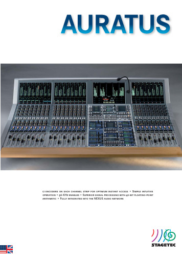
12 encoders on each channel strip for optimum instant access • Simple intuitive operation • 96-KHz enabled • Superior signal processing with 40-bit fl oating-point arithmetic • Fully integrated into the NEXUS audio networkAURATUSThe basic idea behind the AURATUS was to develop a compact digital con-sole suitable for predefi ned workfl ows in radio and TV production. Therefore AURATUS features not only a hardwired bus structure but also a user inter-face optimised for quick and simple operation. This ensures that new users will experience a shallow learning curve and secure operation. All relevant channel parameters are adjusted easily using the dual encoders in the chan-nel strip, or alternatively in the master section.The console dimensions are designed for optimal access to all controls and easy viewing of displays and indicators. AURATUS offers a very comfort a ble and convenient working depth. Furthermore, the meter bridge is ex t reme l y low due to the 16:10 screens employed. This provides excellent visual con-tact with the recording studio, video screens / or the stage.AURATUS has several features designed specifi cally for the broadcaster such as audio-follows-video features, remote-controlled fader (On/Off) function, two freely assignable function keys per channel, extensive cue-light signalling, customizable N-1 buses, and timers capable of counting down as well as up.The NEXUS XCMC plug-in card, which is just 3 U × 4 HP in size, handles all the AURATUS audio processing and control data. The card has full access to all audio resources on the NEXUS network and offers the full number of channels and buses even at a sampling rate of 96 KHz.AURATUS supports stereo and multichannel confi gurations. Depending on the actual confi guration, the following resources are available: 46 or 54 input channels, 4 stereo groups, 4 stereo sums, 2 stereo aux buses, 4 mono aux buses, 8 mono mix-minus (N–1) buses, stereo or 5.1 monitoring buses for monitoring the live mix- or playback.The AURATUS offl ine editor offers time and cost benefi ts on tight production schedules. The offl ine editor makes it possible to confi gure an AURATUS while it is still in use on another production. All preparatory work including channel assignments, channel confi gurations etc. are made in a stand-alone editor application running on a Windows PC. Projects are then loaded into the console from SD cards. It also works the other way round. Projects are imported from the console for further processing in the offl ine editor. Console•Modular, custom confi guration, up to 24 faders•Free assignment of audio channels to channel strips•8 operating layers, freely assignable•Instant access to 2 pre-selected layers per channel strip•Master section for monitoring, automation, Logic Control, and commu-nications•Ultra-low power consumption — 16 channel strips consume just86 watts•Console does not require a fan•Talkback-microphone port•Script rest (optional)•Gooseneck / console lamps (optional)User Interface•12 encoders with LED arcs and 14 illuminated keys per channel strip •OLED displays for channel name and layer assignment indication•Hi-res TFT modules for viewing meters and other parameters •Optional integrated NEXUS control PC with built in keyboard•Master section with dual concentric rotary encoders and graphical TFT displays for direct access to console functions such as:• Signal-processing modules• Monitoring path• Bus routing• Automation menu (snapshots)• Timer• TFT displayDisplays and Indicators•Hi-resolution level and dynamics meters on each channel strip:• G raphic EQ curve and panner position display• D ynamics module curve view• B us routing (including pre/post, mute and control groups)• T ouch-controlled information pop-up window for displaying numeric values of recently adjusted mixing parameters•Hi-resolution level and dynamics meters on the master TFT screen:• P ermanent level metering of all bus channels• F urther graphical display areas with characteristics curves• T imer view: 2 independent timers that can be controlled by internal or external eventsAdditional Functions•Stereo link: Input-channel stereo linking (including dynamics side-chain key signals)•Link groups: Audio parameters of multiple channels can be grouped for simultaneous control and adjustment•Master-slave groups: Link selected channels to any master channel •Spill: Instant access to audio parameters which are not available on the console surfaceInputs and outputs•Custom confi gurable I/O interfaces provided by the NEXUS audio network•Microphone inputs: 32-bit TrueMatch A/D converter, > 158 dB (A) dyna-mic range @ 24 dBu•Line inputs: 24-bit TrueMatch A/D converter, > 133 dB (A) dynamic range @ 24 dBu•Line outputs: 24-bit D/A converter, 131 dB (A) dynamic range (typical) @ 24 dBu•Digital audio formats: AES/EBU, AES 42 and S/PDIF, MADI, ADAT, TDIF, SD-SDI and HD-SDI, Dolby E®, Dante•Sample rates 44.1/48 kHz, 88.2/96 kHz•Sample-rate converters (either standard or optional depending on the card type)•XLR, BNC, RJ45, fi bre-optic, or D-Sub ports Console Ports•2x Headphones outputs (6.3 mm jack sockets)•Meter/Goniometer (8 channels): D-sub (15-pin)•1x Talkback microphone: XLR-3, female•Nearfi eld speakers: XLR-3, maleMonitoring Paths• 5.1 monitoring channel (2.0 monitoring channel in stereo mode)•Stereo channel (“Play Back Channel”)• 5.1 solo bus (stereo bus in stereo mode)•Stereo PFL busStatic Automation• A snapshot stores the audio parameters of all processing channels for later recall. Each project holds up to 99 snapshots.•Partial snapshots are also possible, storing only selected settings. Logic Control•Many AURATUS parameters are integrated into the fl exible and comprehensive NEXUS Logic Control system•Audio-follows-video function includes remote-controlled dynamics •Fader-On-backstop function can be queried•40 freely confi gurable user keys in the central master section •Freely confi gurable display areas on the central TFT screen SynchronisationThe NEXUS / AURATUS system synchronises to the following sources:•NEXUS XCPU controller cards with high-precision word clock generators as studio master clock•External word clock or video (requires NEXUS XSYNC card)•Digital audio inputs•Word-clock-failure auto detection and click-free switchover to different source in order of priorityAURUS, AURATUS, CRESCENDO, ON AIR fl ex, CANTUS, CINETRA, NEXUS, and TrueMatch RMC Series are developed and produced by Stage Tec Entwicklungsgesells-chaft in Germany.AURUS , AURATUS , CANTUS , NEXUS , and TrueMatch are national and international registered trademarks of Stage Tec Entwicklungsgesellschaft für professionelleAudiotechnik mbH, Berlin (Germany). Neither presence nor absence of trademark or brand designations or trade descriptions in this manual should be regarded as affecting the legal status of any trademark.The information given in this manual is subject to change without notice. Errors excepted.Stage TecEntwicklungsgesellschaft für professionelle Audiotechnik mbH Tabbertstraße 10-11D-12459 Berlin /G ermany Phone: +49 30 639902-0Telefax: +49 30 639902-32E-Mail: offi***************Signal Processing•40-bit fl oating-point format•Processor-card connection through a single RJ45 link carrying both control messages and the digital audio needed for talkback and moni-toringSignal-Processing Modules (per Channel)•Input Gain•Expander / Noise Gate•EQ & Filter (Multiband, High-Pass & Low-Pass Filter, High & Low Shelving)•Delay •Insert•Direct-Out (Pre/Post Fader)•Compressor / Limiter •Mute•Pre/post-fader bus routing (Aux, N–1)•Pre/post fader listening & metering •Pan (multichannel capable)Reliability•Redundant power supplies (AURATUS and NEXUS), fi bre-optic cables and cards•Automatic self-test and error-message routing via NEXUS •Hot-swap enabledVersions•Consoles available with 8, 16, or 24 channel strips •Custom master-section positioning •Variants: desktop, fi tted, or with console stand •Also available with narrow side panelsPhysical Dimensions•Control surface operating depth: 625 mm •Channel spacing: 38 mm •Console depth: 777 mm•Width (with standard side panels): 814 mm (8 faders), 1146 mm (16 faders), 1479 mm (24 faders)•Height: 313 mm (desktop variant), 1033 mm (with stand)。
园林景观规划设计作品全集景观资料
园林景观规划设计作品全集景观资料《JJR》G002 国外经典建筑书籍《DESIGN GROUP规划、景观设计红皮书》G003 建筑规划《Tract_Landscape Architects Urban》地球景观G004 贝尔高林景观设计事务所作品集《BELT COLLINS》G005 原版景观规划图书《约翰·波特曼Portman事务所》G006 原版景观规划图书《公共环境标识设计》G007 城市规划公园景观design for fun playgrounds儿童游乐场所设计G008 Landscape Architecture and townplanning 荷兰城镇景观规划G009 The Vanguard Landscapes and Gardens of Martha Schwartz玛莎.施瓦兹的先锋景观庭院G010 PETER W ALKER AND PARTNERS LANDSCAPE ARCHITECTURE 景观设计G011 小区景观资料城市广场规划设计方案《SPACES WATER 4》G012 DESIGN MASTERS VOL.1 国际景观大师1GO13 原版电子扫描图书光碟-德国规划《wettbewerbe aktuell I 》GO14 wettbewerbe aktuell II 德国规划IIGO15 wettbewerbe aktuell III 德国规划IIIGO16 wettbewerbe aktuell IV 德国规划IVGO17 wettbewerbe aktuell V 德国规划VGO18 wettbewerbe aktuell VI 德国规划VIGO19 wettbewerbe aktuell VII 德国规划VIIGO20 wettbewerbe aktuell VIII德国规划VIIIGO21 景观园林规划图书《Urban Landscape Design (japan)》城市景观GO22 景观园林规划图书《METAMORPH VECTORS 》国外城市规划GO23 景观园林规划图书《nederlandse》城市景观设计GO24 日本最新景观设计1GO25 日本最新景观设计2GO26 日本最新景观设计3GO27 水空间建筑设计参考资料集《Water Architecture》GO28 景观园林图书《2006 COMPETITIOONS I》2006景观设计GO29 景观园林图书《2006 COMPETITIOONSII》2006景观设计GO30 景观园林规划参考资料集《世界景观大全02》GO31 景观园林规划参考资料集《世界景观大全03》GO32 景观园林规划参考资料集《世界景观大全04》GO33 国外经典建筑书籍《URBAN SPACES no.1都市空间NO.1GO34 国外经典建筑书籍《Urban Spaces No.2 》城市空间GO35 国外经典建筑书籍《Urban Spaces No.3》建筑公园设计GO36 景观园林规划图书《Urban Spaces No.4 》城市广场空间规划设计4 GO37 景观园林规划图书《景观手绘图典藏(EDSA亚洲)》20.0元GO38 景观园林规划图书《A Public Space》GO39 景观园林规划图书《SKETCHING WITH MARKERS》GO40 景观园林规划图书《landscrapers外文书》GO41 世界景观设计GO42 高楼大厦高层景观SKY GARDENS 空中花园GO43 别墅庭园景观设计作品《NEW DECORATED GARDEN》GO44 Great Spaces Small Houses 住宅景观绿化环境规划设计GO45 Backyards And Boulevards 城市街道道路地砖铺设GO46 景观园林规划图书《YOU ARE HERE 》GO47 Pools Piscine 泳池设计GO48 ALLAIN PROVOST景观绿化环境规划设计GO49 景观园林规划图书《DESIGN & EXPLORATION》设计元素GO50 景观园林规划图书《KISHO KUROKAW A》GO51 景观黑皮书01GO52 景观黑皮书02GO53 景观黑皮书03GO54 景观黑皮书04GO55 景观黑皮书05GO56 景观黑皮书06GO57 景观黑皮书07GO58 景观黑皮书08GO59 景观黑皮书09GO60 城市景观雕塑与景观小品30.0元2.19GG061 城市景观设施40.0元3.50GG062 中国景观设计年刊第一期·上篇G063 中国景观设计年刊第一期·上篇G064 中国景观设计年刊第一期·上篇H001最新日本庭园设计1门·围墙·树篱·竹篱8.0元H002最新日本庭园设计2庭园通道8.0元H003最新日本庭园设计3主庭·茶庭·内庭8.0元H004最新日本庭园设计4岩石·流水·净手钵·石灯8.0元H005最新日本庭园设计5小庭园8.0元H006最新日本庭园设计6花与草的庭园8.0元H007造园书系日本景观设计师户田芳树H008造园书系日本景观设计师三谷徹·长谷川浩己H009造园书系日本景观设计师佐佐木葉二H010造园书系日本景观设计师枡野俊明H011当代国外著名景观设计师作品精选斯蒂芬·斯廷森设计事务所H012当代国外著名景观设计师作品精选迈克尔·鲍尔斯顿H013当代国外著名景观设计师作品精选雷蒙德·容格拉斯H014当代国外著名景观设计师作品精选托弗尔·德莱尼H015当代国外著名景观设计师作品精选枡野俊明H016当代国外著名景观设计师作品精选马里奥·谢赫楠H017景观设计1·屋顶绿化和社区花园H018景观设计2·住宅小区景观设计H019景观设计3·城市和里山森林的维护H020景观设计4·日本年度景观设计作品H021景观细部图集1H022景观细部图集2H023景观细部图集3H024花园别墅造园实例图册:1·门·围墙·通道·车库7.0元H025花园别墅造园实例图册:2·石·水·小品7.0元H026花园别墅造园实例图册:3·小庭园7.0元H027花园别墅造园实例图册:4·树木·草坪·花卉7.0元H028世界建筑空间设计水景建筑空间1 1H029世界建筑空间设计水景建筑空间2 1H030世界建筑空间设计水景建筑空间3 1H031世界园林和城市景观集萃1H032世界园林和城市景观集萃2H033DA建筑名家细部设计创意1H034DA建筑名家细部设计创意2H035DA建筑名家细部设计创意3H036DA建筑名家细部设计创意4H037园林景观设计详细图集1H038园林景观设计详细图集2H039园林景观设计详细图集4H040园林景观设计详细图集5H041国际环境与造景H042德国生态水景H043北京地区水生植物H044植物造景苏雪痕H045风景园林徜徉录H046世界景观设计文化与建筑的历史IH047世界景观设计文化与建筑的历史ⅡH048外国造园艺术H049中建标_环境景观室外细部构造H050H050 景观设计全套相关重要规范H051园林景观设计资料集01园路·踏步·铺地8.0元H052园林景观设计资料集02水景桥8.0元H053园林景观设计资料集03园林雕塑小品8.0元H054园林景观设计资料集04门窗·墙垣·栏杆8.0元H055园林景观设计资料集05园林公用设施8.0元H056园林景观设计资料集06园林建筑8.0元H057园林景观设计资料集07园林石景8.0元H058园林景观设计资料集08园林植物8.0元H059景观大师作品集1 8.0元H060景观大师作品集2 8.0元H061园林设计经典景园铺装艺术H062园林设计经典景园石材艺术H063园林设计经典景园水体艺术H064园林设计经典园景硬质覆盖艺术H065园林设计经典园林水景设计H066园林设计经典园林装饰小品H067园林设计经典造园初学者指南H068现代最具影响力的园林设计师H069 园艺设计大全1H070 园艺设计大全2H071 园林构成要素实例解析.植物H072 园林构成要素实例解析.水体H073 园林构成要素实例解析建筑H074 园林构成要素实例解析土地H075 居住区景观设计ⅠH076 居住区景观设计ⅡH077 居住区景观设计ⅢH078 居住区景观设计ⅣH079 生态环境艺术植物造景图册·花H080 生态环境艺术植物造景图册·树H081 西方造园变迁史从伊甸园到天然公园H082 绿化空间与景观建筑-薛健H083 园林设计——造园意匠论H084 景观设计学H085 新技术庭园H086 景观建筑H087 园林·庭院设计H088 创意空间H089 日本庭园设计105例H090 世界城市景观- 薛健环境艺术设计研究所H091 21世纪庭园H092 外国花园H093 绿化空间与景观建筑H094 设计结合自然H095 说园H096 说园(插图本)H097 园论H098 中国造园论H099 城市景观设计H100 中国园林鉴赏辞典H101 世界名园丛书爱尔兰园林H102 世界名园丛书德国园林H103 世界名园丛书法国园林H104 世界名园丛书荷兰与比利时园林H105 世界名园丛书西。
美制螺钉规格
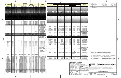
703461 704060
HW000046
Bolt Bolt Bol
HEX HEX HEX
5 - FIG. 2 5 - FIG. 2 5 - FIG. 2
1/4-20 5/16-18 3/8-16
1.50 0.750 1.500
662A PASSIVATED OR DETERGENT 306 SSTL WASH SODIUM HYDROXIDE 306 SSTL PASSIVATED 306 SSTL PASSIVATED FULL THREAD & 662A PASSIVATED OR DETERGENT WASH SODIUM HYDROXIDE PASSIVATED PASSIVATED PASSIVATED PASSIVATED PASSIVATED HOT DIP GALV FULL THREAD & HOT DIP GALV. TYPE BT PASSIVATED
3
AFL Part Number C207227-0375 C207227-0500 70438 C207227-1000 HW000036 C206932-0375 C206932-0437 C206932-075 C206932-0500 C206932-2500 C206932-3500 C206932-4250 C206698-0250 C206698-0375 C206698-0500 C206698-0875 C206698-4750 704892 704921 704922 C205027-0250 C205018-0312 704378 C205690-0500 C205690-0625 C205402-0375 C205402-0500 704914 C220198-0312 C204460-0500 C206939 704461 704934 Description Screw Screw Screw Screw Screw Screw Screw Screw Screw Screw Screw Screw Screw Screw Screw Screw Screw Screw Screw Screw Screw Screw Screw Screw Screw Screw Screw Screw Screw Screw Set Screw SLOT Bolt Bolt Screw LAG Type PHIL PHIL PHIL PHIL PHIL Tip Style PAN HEAD PAN HEAD PAN HEAD PAN HEAD PAN HEAD SHT - FIG 3 - FIG.1 3 - FIG.1 3 - FIG.1 3 - FIG.1 3 - FIG. 1 PASSIVATED PASSIVATED PASSIVATED PASSIVATED PASSIVATED PASSIVATED PASSIVATED PASSIVATED PASSIVATED PASSIVATED 100°, PASSIVATED PASSIVATED PASSIVATED PASSIVATED PASSIVATED PASSIVATED PASSIVATED PASSIVATED 662A PASSIVATED OR DETERGENT WASH SODIUM HYDROXIDE Thread Size Size Length #8-32 0.375 #8-32 #8-32 #8-32 #8-18 0.500 0.500 1.000 0.250 0.375 0.4375 0.750 0.500 2.500 3.500 4.250 0.250 0.375 0.500 0.875 4.750 0.500 1.000 0.375 0.250 0.312 0.500 0.500 0.625 0.375 0.500 1.250 0.312 0.500 2.000 1.250 3.000
莱宝真空泵D65B分解图
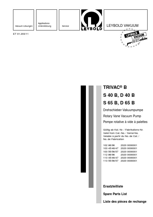
Siehe Abb.2 / See fig.2 / Voir fig.2 TRIVAC 40/65 B
S40B D40B S65B D65B
Benennung
Specification
Désignation
1
4 4 4 4 Sechskantmutter
2
1 1 1 1 Stehbolzen
3
1 1 1 1 Formfilter
Vakuum-Lösungen
ApplikationsUnterstützung
ET 01.203/11
Service
LEYBOLD VAKUUM
TRIVAC® B S 40 B, D 40 B S 65 B, D 65 B
Drehschieber-Vakuumpumpe Rotary Vane Vacuum Pump Pompe rotative à vide à palettes
St
0,9 x 5,4 x 35 St
ø21,5 x 57
PA
16 x 2,5
FPM
ø16 x 12,5
FPM
ø54 x 3
Al
M4 x 16
DIN 7513
M8 x 16
DIN 912
63,5 x 89,5 x 15,3 Al-Leg.
88,5 x 62,5 x 0,5 AFM
305 x 234 x 117 Al-Leg.
12
1 1 1 1 Ringschraube
13
1 1 1 1 Dichtung
14
4 4 4 4 Zylinderschraube
15
1 1 1 1 Zwischenflansch
控制室的抗爆设计2011-09

规范由来
• 《抗偶然爆炸结构(设计手册)》(Structures to Resist the Effects of Accidental Explosions)(TM5-1300)是另外一本有关建筑物抵抗爆 炸作用的研究方面最早、最全面的文献之一。该书是美国陆海空三军 司令部于1969年联合出版,1981年美国国防部组织编委会对该手册 进行修订,修订工作考虑了69年出版以来许多科研新成果,增补了许 多新内容,于1990年出版。该书对弹药的研制、试验、贮存、维护、 改进、检验等设施的防护结构设计具有重要的参考作用。
0.09 0.138 0.138-0.207
关于爆炸-对设施的危害
0.159 0.172 0.207 严重结构损坏的最低限度 砖砌的房屋受到50% 的破坏 工厂厂房里的大型机器 (3000 lb) 遭到少许的损坏 钢结构的建设物被扭曲并脱离地基 无结构的钢板建筑物被破坏 储油罐破裂 轻工业厂房的复合钢结构破裂 木杆被折断 在建筑物里的大型水压机 (40,000 lb) 轻微损坏 房屋几乎完全被毁坏 装货的货车箱倾覆 没有被加固、8-12"厚的砖块因扭曲/弯曲而失效 装货的货车车箱完全被毁坏 房屋可能完全损坏 大型机床 (7000 lb) 被移动并遭严重损坏 特大机床 (12,000 lb) 幸免 弹坑边的极限
规范由来
• Flour Daniel Practice: Flour Daniel的这本抗爆分析指南以ASCE的 《石油化工设施的建筑物抗爆设计》为基础,简明扼要地阐述了箱型 建筑物在爆炸荷载作用下的受力概念和计算方法,并给出了与《石油 化工设施的建筑物抗爆设计》中相同的例题,但是其控制标准不同, 其前墙容许延性比限值为10,而前者为3。Flour Daniel specification: Flour Daniel 的一本有关抗爆控制室的设计规定。它以《化工装置新 建控制室布置和建造指南》(SG-22)为基础,将其中的内容具体应 用到项目的设计规定中。 • 国内国防方法,是国内关于TNT爆炸方面的一些经验总结。虽然目前 国内抵抗TNT爆炸的抗爆结构(建筑物)的计算方法尚未有统一规定, 但该资料从冲击波荷载的确定、结构等效静载的计算、结构计算等三 个方面对该类建筑物设计计算给出了较为全面的阐述。并根据其近几 年来的工作实践,参阅了部分国内外资料,总结了个别工厂的爆炸事 故经验,就化爆空气冲击波作用下,对嵌入式建筑物的结构计算问题 进行分析研究。
景观设计书籍大全
景观设计书籍大全景观设计书籍大全G001 园林景观规划设计作品全集景观资料《JJR》G002 国外经典建筑书籍《DESIGN GROUP规划、景观设计红皮书》G003 建筑规划《Tract_Landscape Architects Urban》地球景观G004 贝尔高林景观设计事务所作品集《BELT COLLINS》G005 原版景观规划图书《约翰·波特曼Portman事务所》G006 原版景观规划图书《公共环境标识设计》G007 城市规划公园景观design for fun playgrounds儿童游乐场所设计G008 Landscape Architecture and townplanning 荷兰城镇景观规划G009 The Vanguard Landscapes and Gardens of Martha Schwartz玛莎.施瓦兹的先锋景观庭院G010 PETER WALKER AND PARTNERS LANDSCAPE ARCHITECTURE 景观设计G011 小区景观资料城市广场规划设计方案《SPACES WATER 4》G012 DESIGN MASTERS VOL。
1 国际景观大师1 GO13 原版电子扫描图书光碟—德国规划《wettbewerbe aktuell I 》GO14 wettbewerbe aktuell II 德国规划II GO15 wettbewerbe aktuell III 德国规划III GO16 wettbewerbe aktuell IV 德国规划IV GO17 wettbewerbe aktuell V 德国规划V GO18 wettbewerbe aktuell VI 德国规划VI GO19 wettbewerbe aktuell VII 德国规划VII GO20 wettbewerbe aktuell VIII德国规划VIII GO21 景观园林规划图书《Urban Landscape Design (japan)》城市景观GO22 景观园林规划图书《METAMORPH VECTORS 》国外城市规划GO23 景观园林规划图书《nederlandse》城市景观设计GO24 日本最新景观设计1 GO25 日本最新景观设计2 GO26 日本最新景观设计3GO27 水空间建筑设计参考资料集《Water Architecture》GO28 景观园林图书《2006 COMPETITIOONS I》2006景观设计GO29 景观园林图书《2006 COMPETITIOONSII》2006景观设计GO30 景观园林规划参考资料集《世界景观大全02》GO31 景观园林规划参考资料集《世界景观大全03》GO32 景观园林规划参考资料集《世界景观大全04》GO33 国外经典建筑书籍《URBAN SPACES no.1都市空间NO.1 GO34 国外经典建筑书籍《Urban Spaces No。
Motorola 无线手机产品说明书
MAINTENANCE MANUAL GPS TIMING MODULE ROA 117 2260/1, 2ericssonzSPECIFICATIONSInput V oltage +5 Vdc 10%Current Drain 67 Milliamps (Typical)Operating Temperature -30ºC to +60ºCDimensions 8.0 inches long x 4.0 inches wideConnector P1+5 Vdc A30, A31, B30, B31GroundA1, B1, C1, C12, A32, B32, C32Ericsson Inc.Private Radio Systems Mountain View RoadLynchburg, Virginia 24502AE/LZB 119 1875 R1A1-800-528-7711 (Outside USA, 804-528-7711)Printed in U.S.A.DESCRIPTIONG lobal P ositioning S atellite (GPS) Timing Module ROA 117 2260 is used in the GPS Simulcast Synch Shelf. There are multiple Synch Shelves in the GPS Simulcast System, one at the Control Point and one at each Transmit Site. Each Synch Shelf has two GPS Timing modules, A and B. Each of these are fully redundant.The Timing Module plugs into slots 9 & 10 of the Synch Shelf located at both the Control Point and the Transmit Site.At the Control Point, the Timing Module is an ROA 117 2260/1 and the module at the Transmit Site is an ROA 117 2260/2. One difference is that there is a different PROM in socket XU1 with different programming used between the two locations. Also, front panel LED’s and labels differ: CPTM for C ontrol P oint T iming M odule (Figure 1) and TXTM for T ransmit(X)T iming M odule (Figure 2).The Timing Module has three functions. Each function, though related, is performed differently at each location, control point or transmit site. At the Control Point, these functions:•Generate 300 Hz FSL (Frame Sync Line)•Generate Composite References•Select 9600 Hz ClocksAt the Transmit site, these functions:•Select 9600 Hz clocks•Recover references from composites•Control T1 delayRefer to Figures 1 and 2. The following is a description of the LED indicators found on the front panel of the modules.•PWR - Green LED indicates when power is applied to the module.•ACTV - Green LED indicates when this is the active module.•MAJ - Red LED indicates when a major alarm condition exists.•MIN - Yellow LED indicates when a minor alarm condition exist.•GPS - Yellow LED indicates that there is no signal coming from the GPS receivers. This is at the Con-trol Point.•LL - Yellow LED, at the transmit site, indicates that there is no signal coming from the GPS receivers andthe Land Line signals are being used.•FSL - Yellow LED indicates there is a loss of the Frame Synch Line at the Control Point.•REF 2 - Yellow LED indicates when there is a loss of composite reference 2 at the Transmit Site.•PROG- Switch resets PROM U1 and the Xilinx (FPGA) module U4 to the initial state.•TEST - Connector is an RJ12, 8-Pin connector used for test purposes (Refer to TEST AND TROU-BLESHOOTING). Connector P1 DefinitionCopyright © September 1996, Ericsson Inc.NOTERepairs to this equipment should be made only by an authorized service technician or facility designated the supplier. Any repairs,alterations or substitution of recommended parts made by the user to this equipment not approved by the manufacturer could voidthe user’s authority to operate the equipment in addition to the manufacturer’s warranty.This manual is published by Ericsson Inc., without any warranty. Improvements and changes to this manual necessitated by typographical errors, inaccuraciesof current information, or improvements to programs and/or equipment, may be made by Ericsson Inc., at any time and without notice. Such changes will be in-corporated into new editions of this manual. No part of this manual may be reproduced or transmitted in any form or by any means, electronic or mechanical, in-cluding photocopying and recording, for any purpose, without the express written permission of Ericsson Inc.AE/LZB 117 1875 R1A1Figure 1 - Control Point Timing Module Front PanelFigure 2 - Transmit Site Timing ModuleAE/LZB 117 1875 R1A 2CIRCUIT ANALYSISFunctional circuitry is primarily contained in a Xilinx 3190A FPGA(F ield P rogrammable G ate A rray) integrated circuit (U4). This circuitry is programmed differently for con-trol and transmit applications.The GPS Timing module has hot standby capability. Cir-cuitry outside the FPGA provides this capability as well as I/O interfaces and a P hase-L ock-L oop (PLL). The PLL is used at the transmit site.Xilinx 3190A FPGA U4 is wired in master serial mode, which determines how programming is accomplished (Figures 4 & 5). These figures are included for those familiar with Xilinx technology and are not described within this document.At power up, following the release of the Reset/reprogram push-button switch S1, or following automatic detection of a Xilinx fault, data PROM U1 is read serially into U4. A watchdog function is performed by 555 timer, U5 in the Activity Detector circuit. This timer causes a reprogramming if the 9600 Hz selected clock is not provided by U4 (automatic Xilinx fault detection).Crystal B1 provides a 4.9152 MHz clock used internally by the Xilinx logic.This board operates from a single +5 volt supply. An on-board thermister fuse (F1) prevents module failure from causing this shelf supply to collapse.Input signals arrive as RS-422 levels and are converted to TTL logic levels by RS-485 receivers U9, U11, and U14. Input fault lines connect directly to U4, as they arrive at TTL logic levels. The outputs driving the GPS ReSync modules (located in the same shelf) are buffered with tri-state line drivers U7, U13 and U15. The RS-422 level outputs are generated using RS-485 drivers U16-U20. The tri-state controls on all these drivers are used by the hot standby circuitry to turn the output to high impedance when the module is in hot standby. The circuitry attached to RC_IN and RC_OUT provides operational/hot-standby selection; these leads tie through the backplane to the companion module.PLL U3 provides a de-jitter filter with zero phase shift on the recovered landline 9600 clock. This PLL is used only at the transmit site.CONTROL POINTThe major functions performed at the Control Point areshown in Figure 3. The GPS signal selection block selects a9600 clock and 1 pps signal from either of the redundant GPSlocked clock sources. The Clock Generator block generates a19200 Hz clock for use by the other blocks. The 300 HzGenerator generates the 300 Hz required by the ReSync bydividing the selected 9600 Hz by 32. It also ensures that thephase of this 300 Hz is proper relative to the F rame S ync L ine(FSL) input. The Composite Reference Generator takes theselected 9600 Hz clock and inserts tags at the proper times tocreate reference signals that contain:•Composite Reference 1 contains 9600 Hz clock plustags for 300 Hz and pseudo FSL.•Composite Reference 2 contains 9600 Hz clock plustags for 1 pps.These Composite References are extracted at the transmit site.The 300 Hz generator and the Composite Reference Generatorare implemented as state machines.TRANSMIT SITEThe major functions performed at the transmit site are shownin Figure 4. There are similarities to the Control Point. The clockgenerator generates a 19,200 Hz clock for internal use; the GPSsignal selection block selects the 1 pps and 9600 Hz clock fromthe two redundant GPS locked clock sources. In addition it alsoprovides for selection of the landline 9600 Hz in the unlikelyevent that both GPS sources are failed. The Signal Recoveryblock is the corresponding function of the Composite ReferenceGenerator at the Control Point. It extracts the 9600, 300 1 ppsand pseudo FSL from the reference signals. The 9600 Hzlandline is routed off the Xilinx IC (U4) to be filtered by thePLL and returned for use by the T1 delay module. The T1 delaymodule examines the selected GPS signals (1 pps and 9600) andcompares their phase to the corresponding landline signals. Ifcertain “hysterisis hurdles” are exceeded the number of T1cycles of delay desired are serially sent to the Intraplex MUXwhere the actual delay is accomplished. This Delay Controlblock and Signal Recovery block are implemented with statemachines.SELECTORC L O C KTO CPTC(RS-422)9.6 DATA ANDCLOCK TO MUX(RS-422)TO MUX(RS-422)(RS-422)GPS BGPS A9.6Figure 3 - Functions at the Control Point (CPTM)AE/LZB 117 1875 R1A3GPS AGPS BTO RESYNC MODULESTO MUX F R O M G P SA L A R M Figure 4 - Functions at the Transmit Site (TXTM)1U U 00 H zS L *d r i v eS L *t e s to m p R e f 1o m p R e f 2Figure 5 - Xilinx 3190A FPGA at the Control PointAE/LZB 117 1875 R1A4TEST AND TROUBLESHOOTINGThe GPS Timing operates in two functionally different applications. Some of the functionally is the same for both applications and some is complementary to the other applica-tion. The module contains a PROM which holds the configu-ration information for the application.The functions to be tested are described previously for the control point and transmit site application.Signal on test connector P2:Control PointPin 1 - Composite Ref. 1Pin 2 - 1pps GPS Pin 3 - nc Pin 4 - FSL*Pin 5 - Selected 9600 (ReSync)Pin 6 - 300 outPin 7 - Composite Ref. 2Pin 8 - nc Transmit SitePin 1 - T1 Delay Data Pin 2 - 1pps GPS Pin 3 - 1pps landline Pin 4 - FSL*Pin 5 - Selected 9600 (ReSync)Pin 6 - 300 out Pin 7 - ncPin 8 - 9600 PLL * Pseudo FSL.To test as a Control Point module:The module must be powered up and supplied with GPS signals (9600 Hz, 1pps and an FSL). The presence of the “selected” signals at all the proper outputs and of the gener-ated signals (300, Comp Ref. 1 and Comp Ref. 2) must be verified. This is done for GPS “A” and “B”. The generated Comp Ref. 1 and Comp Ref. 2 need to be checked to verify the “tag” is placed consistently following the corresponding event.With no signals present, the MINOR alarm goes active;the green activity (ACTV ) LED goes out and the red MAJOR alarm LED comes on.To test the Transmit Site:It is desirable to have an operational module in the Control Point mode to provide the Comp Ref. 1 and Comp Ref. 2signals. Signal selection is checked similar to that done at the Control Point with the additional fault mode of reverting to landline 9600 if neither GPS source is present. A second GPS source allows a precise time difference between the landline 1pps and the “direct” 1pps to test the T1 delay portion of the module. A known time difference is programmed onto the local GPS and the T1 delay output is examined to verify that a new delay value is sent. As there is no MUX (& T1 delay module) the correction will successively add to itself.U TS 2S 01p p s L LS E L 300T 1_C L O C A S M _C L C O M P _R E F 1Figure 6 - Xilinx 3190A FPGA at the Transmit SiteAE/LZB 117 1875 R1A5*COMPONENTS ADDED, DELETED OR CHANGED BY PRODUCTION CHANGESDATACLKRESET/OE(OE/RESET)CE G N DC E OVppVccU1PROMRON 107 786 CPTM (XC1765D)RON 107 787 TXTM(XC1765D)U2DUAL D FLIP/FLOPRYT 306 2003/C (74HC74)á = Transition from low to high levelQ0 = The level of Q after the previous clock pulse* = Nonstable, don’t preset when PR and CLR are set highX = Any input, including transition18916U3PHASE-LOCK-LOOPRYT 306 6075/C (74HCT4046)CONNECTIONS PARTS LIST IC DATAAE/LZB 117 1875 R1A 6Positive Logic: Y=A • BPositive Logic: Y=A+B26U4XILINXRYT 139 003/5C(3190A)V DSCHTHRESCONTGNDTRIG OUTU5555 TIMER RYT 108 6003/CG N DVcc 4B 4A 4Y 3B 3A 3Y2Y 2B2A 1Y1B1A U6QUAD NAND GATERYT 306 2001/C (74HC00)G NDVcc C4A4Y4C3A3Y3Y2A2C2Y1A1C1U7, U13, U15TRI-STATE BUFFER RYT 3066029/C (74HC125)Vcc 4Y 4B 4A 3Y 3B 3AG N D 2B2A 2Y 1B 1A 1Y U8QUAD NORGATERYT 306 2006/C (74HC020)IC DATAAE/LZB 117 1875 R1A7VccB4A4R 04E N 34R 03A3B3G N D B2A2R 02E N 12R 01A1B1U9, U11, U14RS-485 QUAD RECEIVER RYT 109 6079/2C (LTC489)Vcc DI 4DOA 4D O B 4E\DOB 3DOA 3DI 3G N DDI 2DOA 2DOB 2E DOB 1DOA 1DI 1U16 - U20RS-485 QUAD DRIVERRYT 109 6078/1C (LTC486)E EDOA1DOB1DOA2DOB2DOA3DOB3DOA4DOB4CONNECTIONSH: High Level L: Low Level X: Irrelevant Z:HighImpedance (Off)FUNCTION TABLEIC DATAAE/LZB 117 1875 R1A8OUTLINE DIAGRAM AE/LZB 117 1875 R1AOUTLINE DIAGRAM(1078 ROA 117 2260, Rev. B)9AE/LZB 117 1875 R1ASCHEMATIC DIAGRAMSCHEMATIC DIAGRAM(1911 ROA 117 2260, Sh. 1, Rev. B)SCHEMATIC DIAGRAM AE/LZB 117 1875 R1ASCHEMATIC DIAGRAM(1911 ROA 117 2260, Sh. 2, Rev. B)AE/LZB 117 1875 R1ASCHEMATIC DIAGRAMSCHEMATIC DIAGRAM(1911 ROA 117 2260, Sh. 3, Rev. B)AE/LZB 117 1875 R1A This page left blank intentionally。
茅莱特-公司-Parker Pneumatic分部-奔波螺栓操纵器-HUB系列-LTR系列-HTR系

Market Segments and Applications A2FeaturesA3Common Part Numbers - For Process Valve Direct Mount A4-A7Ordering Information - For Process Valve Direct Mount A8-A9Ordering Information - For General Industrial Use A10Specifications A11-A12Engineering Data A13Dimensional DataA14-A17Process Valve Mounting and Shaft Table A18Options A19-A29Shaft OptionsA19-A20Cross-over Vent Module A21Counter-balance Valve Module A22D03 Directional Control Valve Ready A23Feedback and Visual IndicatorA24-A29RACK & PINIONMade from through hardened, high strength alloy steels for long and durable service life.PISTON SEALSPiston lip seals made from abrasion resistant 4300 polyurethane for reliable service. These seals offer a wide temperature range so that this product may be used in a wide variety of applications. Piston seals can be inspected and replaced without disconnecting the load from the shaft. (Employproper safety practices to prevent damage to people or equipment.)THREADED MOUNTING HOLESOur standard mounting uses fourtapped holes re-inforced with stainless steel inserts on the customer mounting face of the housing. Both inch and metric (ISO 5211) are available andprovide direct mounting to a wide range of process valves.STANDARD SHAFT CONFIGURATIONS Our shafts are designed to direct mount to various process valves without the need of additional coupling.HOUSINGAnodized aluminum housing is designed to minimize external fitting and plumbingconnections and rugged enough for the harsh outside environment.SHAFTORIENTATION Mid stroke at 12:00 position is standard.PINION SEALS Dual lobed seal of abrasionresistant materials seals effectively with minimum wear at dynamic conditions.RELIEF VALVEIs designed to prevent the housing from seeing high pressure due to piston seal bypass. Do Not Plug .TAPERED ROLLER BEARINGSAre designed to support large external axial and radial loads applied to the shaft.WEAR BANDS(Not available on HUB009 & HUB018)Filled PTFE bands (std) precisely positionpistons and prevent side loading from scoring cylinder bores.HUB SeriesTorqueOutput (in-lb)Imperial/ Metric Mounting Pattern Shaft Size(female square)FeedbackVisual IndicationPart Number* Additional feedback information on pages A24 thru A29.SAE #6 Ports- page A14 for additional informationTorqueOutput (in-lb)Imperial/ Metric Mounting Pattern Shaft Size(female square)FeedbackVisual IndicationPart Number* Additional feedback information on pages A24 thru A29.SAE #6 Ports with Cross-Over Vent Module- pages A15 & A21 for additional informationTorqueOutput (in-lb)Imperial/ Metric Mounting Pattern Shaft Size(female square)FeedbackVisual IndicationPart Number* Additional feedback information on pages A24 thru A29.SAE #6 ports with counter-balance valve module - pages A16 & A22 for additional informationTorqueOutput (in-lb)Imperial/ Metric Mounting Pattern Shaft Size(female square)FeedbackVisual IndicationPart Number* Additional feedback information on pages A24 thru A29.SAE #6 ports with D03 directional control valve ready - pages A17 & A23 for additional informationShown with solenoid valve for reference only.Without solenoid valve (standard)27 mm HUB 075 -090ZZ-TABLE2DIRECT MOUNT VALVE MODULESThreadports onlyCross-overvent valveincludedTABLE3VISUAL INDICATIONCLine onshaftColorindicator(green on /No visualindicationALine on shaftA Rotary Linear Potentiometer (RLPO),0-40 VDC, position right (standard)HUB037/075B5.00 in1D.87512SAE #6 straight threadCatalog HY03-1800-2USParker PneumaticUnibody Rotary Actuators, HUB SeriesModel Number Code - For General Industrial Applications(Revised 08-03-22)Model Maximum Pressure Rating PSI (bar)Actual Output Torquein-lb (Nm) at Specified Pressure Gear Train Rating Durability (1)Maximum Angular Backlash Minutes Standard Rotation Degrees Displacement in 3 (cm 3)Standard Unit Weight lb (kg)1000 PSI (69 bar)2000 PSI (138 bar)3000 PSI (207 bar)in-lb (2)PSID (3)HUB0093000 (207)300 (34)600 (68)900 (102)400134045900.57 (9.3)9 (4.1)HUB0183000 (207)600 (68)1200 (136)1800 (203)85014204590 1.13 (19)10 (4.5)HUB0373000 (207)1250 (141)2500 (283)3750 (424)157013004090 2.43 (40)22 (10)HUB0503000 (207)1650 (186)3300 (373)5000 (565)270016203090 3.12 (51)28 (12.7)HUB0753000 (207)2500 (283)5000 (565)7500 (848)333013504090 4.86 (79)23 (10.4)HUB1003000 (207)3300 (373)6600 (746)10000 (1130)572517203090 6.25 (102)29 (13.2)HUB1503000 (207)5000 (565)10000 (1130)15000 (1695)9300186025908.9 (145)80 (36)HUB3003000 (207)10000 (1130)20000 (2260)30000 (3390)197001970259017.8 (291)80 (36)Output Torque TableThe Hydraulic Unibody Series (HUB) actuator is a single piece housing/cylinder design that is able to perform in the harshest environmental conditions. Built with a hard coat anodized housing and through hardened, high strength alloy steel pinion and racks, this product is ideal for numerous applications where weather can be a factor. The HUB Series is designed with several add-on valve modules for lower overall integration costs, as well as, an increase in product performance. Multiple feedback and visual indication options are also available.• Rack and pinion design provides excellent efficiency characteristics and minimizes HPU Size • Direct mounting design to numerous process valves allows for minimal integration cost • Integrated valve module options are available for increased performance and reduced plumbing cost• Cross-over vent module - allows for flow between both cylinder ports, thus allowing free rotation.• Counter-balance valve module with Cross-over vent - designed for load holding in both directions and preventing a run-away load situation from occurring. Also allows for flow between both cylinder ports. • D03 Solenoid ready module - manifold block directly mounted to actuator for reduced plumbing and increase in performance • Numerous linear and positional feedback and visual indication options available • Environmentally rugged for reliable performance inharsh conditions1. The durability is defined as the capacity of the gear set to support the stated load without fatigue related gear surface damage. Use the durability rating for high production duty of 1 million cycles and/or high speed applications (180° in less than three seconds or more than one cycle per minute).2. Durability rated output torque.3. Pressure differential between the inlet and outlet ports (non shock).Seal Class Seal Type Wear Ring Type Fluid Medium Temperature Range Pressure Range FiltrationStandard type 14300 Polyurethane U-cup Filled PTFE General purpose, Petroleum-based fluids -40°F to 180°F (-40°C to 82°C)3000 PSI 207 bar Minimum ISO class 17/14 Cleanliness level Fluorocarbon (V)Fluorocarbon Filled PTFE High temperature and/or synthetic fluids -20°F to 250°F -29°C to 121°C 3000 psi 207 bar Nitrile (W)Carboxylated NitrileFilled PTFEWater Glycol, high water content fluids30°F to 180°F 0°C to 82°C3000 psi 207 barSeal MaterialsEffective filtration is vital to the long life and satisfactory performance of a rotary actuator. If the piston seals of a rack and pinion rotary are worn or damaged, fluid which leaks past the piston will enter the gear housing. In the event of internal leakage into the gear housing, the pressure relief valve protects the shaft seal.PTFE Wear Band4300 PolyurethaneDynamic 1 Bearing Load Capacities vs. Operating PressureModel Radial Load (lbs.) R L (per bearing) @Thrust Load (lbs.) R T @Bearing Centers (B C )Overhung Moment (in-lb) R L x (A+B C /2) @1000 PSID (69 bar)2000 PSID (138 bar)3000 PSID (207 bar)1000 PSID (69 bar)2000 PSID (138 bar)3000 PSID(207 bar)1000 PSID (69 bar)2000 PSID (138 bar)3000 PSID (207 bar)HUB0093927382437222690259024900.62243523712307HUB0184030403040302790279027900.62249924992499HUB037644861465843361033603120 1.06683565146194HUB050825879567653424040203810 1.02842381157807HUB0756******* 6750383038303830 1.06715571557155HUB100856085608560446044604460 1.02873187318731HUB150148231428613748123001181011330 1.83271262614325160HUB3001536015360153601278012780127801.83281092810928109NOTES:1. Static bearing load capacities = dynamic values x 1.52. Values listed are “Bearing” moment capacities. Standard male shaft sizes do not provide 4:1 design factor at these operating conditions.3. Larger shaft sizes are available. Consult factory for further details.Low speed, high torque applications typically require class 5 or class 6 lubrication provisions. Parker rotary actuators are assembled with 3% (minimum) Moly extreme pressure grease. This grease should be replaced with each major overhaul.Bearing Load CapacitiesLubricationThrust Load,LBS.(R )T Radial Load,LBS.(R )L AC LB CCatalog HY03-1800-2USParker PneumaticBase Actuator Kit Ordering InformationItem #Description Qty †1Housing 12^Rack 1/23^Piston 2/44^Rack Bolt 2/44a ††Rack Bolt Washer 2/45Plug, SAE 45a*O-ring, Plug, SAE 2/46Pinion 18Bearing 29Bearing Retainer 110Bearing Retainer Set Screw 111Relief Valve 112Name Plate 113*Quad Ring 214*O-ring, Bearing Retainer 115*^Piston Seal2/4Item #Description Qty †16*^^Back-up Ring, Piston Seal2/417*^O-ring, Rack Bolt 2/418*^Back-up Ring, Back Bolt 2/419*^††Wear Band 2/420^Rack Plug 2/021*^O-ring, Rack Plug 4/022*^Back-up Ring, Rack Plug 4/023**Rack Bearing1Unibody Rotary Actuators, HUB SeriesEngineering Data(Revised 09-01-22)* Items included in seal kit † Single rack / double rack qty^ For HUB037 & HUB050, items 19, 20& 21 replace items 2, 3, 4, 15, 16, 17 & 18 in the top cylinder bore†† Not used on HUB009 and HUB018** Only used on HUB150 and HUB300^^ Used with Fluorocarbon andCarboxylated Nitrile seal optionsModel L M N O P BB CC DD**EE FFHUB009/ HUB018SAE #60.80(20.3)0.80(20.3)0.63(16.0)0.2(5.1)1.125(28.6)3.09(78.5)0.22(5.6)--HUB037/ HUB075SAE #60.87(22.1)0.80(20.3)0.63(16.0)0.2(5.1)1.375(34.9)4.17(105.9)0.22(5.6)--HUB050/ HUB100SAE #60.80(20.3)0.80(20.3)0.63(16.0)0.2(5.1)1.375(34.9)4.75(120.7)0.22(5.6)--HUB150/ HUB300SAE#62.5(63.5)--0.0(0.0)1.375(34.9)6.00(152.4)0.0(0.0)6.75(171.5)5.88(149.4)† Thread depth is for Helicoil hole depth may be longer.* F see Shaft Options ** DD is dimension is to the pinion face SAE #6 portsHUB SeriesHUB075 series with female square shaft shown above.HUB075 series with female square shaft shown above.† Thread depth is for Helicoil hole depth may be longer.* F see Shaft Options ** DD is dimension is to the pinion faceSAE #6 ports with cross-over vent moduleHUB SeriesFull open blocked)HUB SeriesModel NOP Q R S T U CC DD**EE FF HUB009/HUB0180.80 (20.3)0.63 (16.0)0.2 (5.1) 2.73 (69.3) 1.45 (36.8) 1.25 (31.7)0.1 (2.5)0.80 (20.3) 3.09 (78.5)0.22 (5.6)--HUB037/HUB0750.80 (20.3)0.63 (16.0)0.2 (5.1) 2.73 (69.3) 1.45 (36.8) 1.25 (31.7)0.1 (2.5)0.69 (17.5) 4.17 (105.9)0.22 (5.6)--HUB050/HUB1000.80 (20.3)0.63 (16.0)0.2 (5.1) 2.73 (69.3) 1.45 (36.8) 1.25 (31.7)0.1 (2.5)0.69 (17.5) 4.75 (120.7)0.22 (5.6)--HUB150/HUB300--0.0 (0.0)2.73 (69.3)1.45 (36.8)1.25 (31.7)1.6 (40.6)0.69 (17.5)6.00 (152.4)0.0 (0.0)6.75 (171.5)5.88 (149.4)SAE #6 ports with counter-balance valve moduleHUB075 series with female square shaft shown above.HUB SeriesSAE #6 ports with D03 directional control valve readyHUB075 series with female square shaft shown above.D03 directional controlCatalog HY03-1800-2USParker PneumaticUnibody Rotary Actuators, HUB SeriesProcess Valve Mounting and Shaft TableUnibody Process Valve Mounting TableFemale Square (Imperial) – Option 1Female Square (Metric) – Option 6Female Double D (Metric) – Option 7Female Double D (Imperial) – Option 2Others available upon request.Customer is responsible for proper sizing and selection of mating shaft.Female Keyed Shaft (Imperial) -Option AFemale Keyed Shaft (Metric, per DIN 6886) -Option GCatalog HY03-1800-2USParker PneumaticUnibody Rotary Actuators, HUB Series Cross-over Vent ModuleItem #DescriptionQty 30Cross-over vent valve132A Cross-over vent block, size 009, 018132B Cross-over vent block, size 037, 075, 050, 100, 150, 300133Cap screw437O-ring2383/16 x 3/4, SS spring pin1Technical DataKit Ordering InformationCartridge FeaturesThe HUB Cross-over module is designed to allow free flow between ports C-1 and C-2 when open. This module can be ordered at the same time as the base actuator (as onefinished good part number) or later with an upgrade kit. Similar to the HUB actuator, this module is designed with a hardcoat anodized housing that is reliable in harsh environmental conditions. This module also utilizes Parker’s proven needle valve cartridge product from Hydraulic Cartridge Systems Division.(2)(1)• Hardened, precision ground parts for durability • Compact size for reduced space requirements • Fine adjustment needle with locking nut • Polyurethane“D”-Ring eliminates backup rings and prevents hydrolysis • All external parts zinc plated(Revised 06-13-22)Catalog HY03-1800-2USParker PneumaticP A Input (active) & exhaust pilot pressure (psi)P E Sum of pressures in exhaust chamber (psi)P L External induced pressure load (psi)P RReaction pressure in exhaust chamber from P A (psi)P R = P A – P friction P E = P L + P RTechnical DataThe HUB Counter-balance module with Cross-over vent is designed for load holding in both directions of actuation and prevents a run-away load situation from occurring. This module is available as part of a finish good actuator or can be integrated in the field with an upgrade kit. As with all other HUB options, this module is designed with a hard coat aluminum housing for durability in harsh conditions.The Counter-balance module also includes the cross-over functionality that was described on pages A18-A19. Similarly, this module allows free flow between ports C-1 and C-2 of the actuator when the needle valve is backed out. This module also incorporates Parker’s proven valve technology from Hydraulic Cartridge Systems Division for the counter-balance valve.Unibody Rotary Actuators, HUB Series Counter-Balance ModuleMHC-010-S*S*Non-Vented(3:1)MHC-010-S*NK(10:1)(3000 PSI)Maximum “H”Counter-balance with adjustabilityMovement of actuator with counter-balance valves05001000150020002500300035004000Input (Active) & Exhaust Pilot Pressure, P A (PSI)E x t e r n a l I n d u c e d P r e s s u r e L o a d , P L (P S I )Cross-over Vent ValveCounter-balance ValveECatalog HY03-1800-2USParker PneumaticUnibody Rotary Actuators, HUB Series D03 Directional Control Valve ReadyItem #Description Qty 35Cap screw 436A Solenoid block, size009, 018136B Solenoid block, size 037, 050, 075, 100,150, 300137O-ring 2383/16 x 3/4,SS spring pin1D03 Directional Control Valve Ready Technical DataThe HUB solenoid ready module is a hard coated anodized aluminum block that allows for D03 valves to be mounteddirectly to the actuator. This option is ideal for applications with limited available space. The reduced plumbing required is also a cost savings during integration. Similar to the HUB’s other options, this module can be ordered as part of the original actuator or added on later with an upgrade kit.D03 Directional Control Valve Ready Kit Ordering InformationShown with solenoid valve for reference only.Without solenoid valve (standard)Item #DescriptionQty 30Cross-over vent valve 131Counter-balance valve234A Cross-over / Counter-balance valve block, size 009, 018134B Cross-over / Counter-balance valve block, size 037, 050, 075, 100, 150, 300135Cap screw 437O-ring2383/16 x 3/4, SS spring pin1Counter-balance Module Kit Ordering Information(Revised 07-13-22)Rotary Linear Potentiometer Feedback0-40 VDC linear position feedback (RLPO)Parker’s 0-40 VDC linear position feedback solution is accurate, reliable, and designed to handle the harshest environmental conditions. The robust hard coat anodized aluminum construction and electroless nickel plated (ENP) steel components make this feedback option ideal foruse in corrosive outside environments. With a low profile design, this solution is perfect for applications where space is a premium.• Environmentally rugged – Hard coat anodized aluminum module and electroless nickel plated (ENP) steel components that are designed to withstand theharshest environmental conditions.• Direct mounting to output shaft – Cam coupled design provides precision rotation position for accurate feedback.• Low profile design - Clearance above the actuator is critical in many systems. The Parker RLPO feedbackmodule has a less than 2" height requirement.• Redundancy capabilities for additional safety requirements – Additional plugged port locatedopposite the RLPO unit that can be used for a second RLPO unit.SpecificationsElectricalResistance values10 K ohmsResistance tolerance (standard)± 15%Linearity tolerance (standard)± 2%Resolution Essentially infinite (<0.01 mm) Output smoothness< 0.1% against input voltage Power @ 40°0.2WTemperature coefficient of element40 ppm/KContact resistance variation< 2%Insulation resistance> 1,000 Mohm @ 500 VDC Dielectric strength 1 minute @ 500 VAC Maximum wiper current1mARecommended wiper current< 1µA MechanicalMechanical stroke (mm)7.0Life expectancy, shaft cycles20 millionVibration15 g/10 Hz to 2,000 Hz Shock50 g/11msWiring DiagramReceptacle Pin LayoutPin D (Yellow)Pin A (Green)(red) C N12Potentiometer Linear MotionCompact linear motion potentiometer features long life with highresolution conductive plastic element. Shaft spring to ensurethe shaft is fully extracted for repeatability and reliability.Resistance (KΩ)Typical Valve PositionPin D - Common PinA - PositivePin D - Positive PinA - CommonAcross D to C Across A to C0°7.2 2.990°19.2Dual module solid state or 4-20 mA position feedbackThe StoneL Quartz series is durable, corrosion-resistant, andversatile, making it ideal for most of your process valve monitoring requirements. The robust epoxy coated anodized aluminum construction makes this platform extremely durable and well suited for use in corrosive, heavy wash down environments. This versatile platform adapts to a wide variety of valve systems. The QX explosion proof version is offered as the standard that will be provided from the factory fully mounted and positioned. Nonincendive and intrinsically options are available upon request.The explosion-proof, water tight and corrosion-resistant enclosure is approved for use in div. 1/zone 1 hazardous areas.1. Enclosure optimized for environment – Explosion proof,water tight and corrosion resistant cover 2. Rapid enclosure access – Screw-on cover allows quickenclosure access, saving you valuable maintenance and set-up time. The cover provides a vapor tight seal and allows entry to internal components in less than five seconds.3. Faster wiring – Pre-wired and labeled terminal strip enablesquick, convenient attachment of field wires.4. Wide variety of switching & communication – Dual modulesensors and communication standard, as well as, continuous signal output available in a 4 to 20 mA position transmitter.5. Quick set cams are easy to adjust – Touch and tune switchsettings allow you to make adjustments in seconds without the use of tools.6. Dual shaft o-ring seals eliminate corrosion – Top inner andbottom outer shaft o-rings seal the drive bushing from both external corrosives and internal contaminants that enter the enclosure.7. Special drive bushing assures long cycle life – The oilimpregnated bronze bushing maintains smooth operation and eliminates the potential for shaft seizure due to actuator shaft eccentricity.8. Space saving visual indication – Visual indicator offersexcellent view ability without sacrificing accessibility or adding to space requirements.Space saving low profile designClearance above the actuator is critical in complex piping systems. The Quartz series clearly displays valve position and encloses all electrical components in an explosion proof compartment with less than 5” clearance requirement.QuartzFor more information regarding this product series please visit StoneL’s website – Valve Open CommonValve ClosedCommonPowerSpecifications - Switching and sensorsSST switching sensors (C)Configuration (2) SST solid state sensorsWire termination for one solenoid OperationNO/NC (cam selectable)Maximum current inrush 2.0 amps @ 125 VAC / VDC Maximum current continuous 0.3 amps @ 125 VAC / VDC Minimum on current 2.0 mA Maximum leakage current 0.5 mA Voltage range8 to 125 VDC 24 to 125 VAC Maximum voltage drop6.5 volts @ 10 mA7.0 volts @ 100 mAWiring diagram (C)Visual indicatorsAvailable with the Quartz Series or as a stand-alone unit. Clearly view valve position status from up to 75 feet. The indicator’s rugged polycarbonate construction makes itresistant to physical damage and tolerant to most corrosives.Dual module systemThe Quartz series is available with the dual module as one of its various configurations. Two solid state sensors and/or communications and other electronics are sealed in for the ultimate in reliability and convenience.Position transmitter - 4 to 20 mAPosition transmitters provide a precise 4 to 20 mA signal on a two-wire DC loop. Control valves and dampers are accurately monitored through their range of travel offering assurance of exact valve position at all times.Load Curve0°90°RED CLOSEDGREEN OPENStoneL Valve Communication Wiring diagram (D, E)90°0°Spare 1Spare 2Spare 3Spare 4Trans +Trans -Transmitter TransmitterBottom SwitchTop SwitchTrans +Trans -CCSpare SpareSpare SpareSpare SpareNO/NC NO/NC Position T ransmitter and SwitchesPosition T ransmitterSpecifications - Position transmitterPosition transmitter (D, E)Output 2-wire 4 to 20 mA Supply source 10 to 40 VDCSpan range35° to 270° (adjustable) Consult factory for special requirements Maximum loading 700 ohmn @ 24 VDC Linearity error +/- 0.85" maximum Cycle life2 million rotations Vibration toleranceAcceptableElectrical schematicFor more information regarding this product series please visit StoneL’s website – Color indicator *Visual indicator replacement kit does not include bracket or hardware.Rotary Linear Potentiometer(Feedback option A & B)StoneL - Quartz(Feedback option C, D & E)StoneL - stand alone visual indicator(Visual Indication option C)NOTE: Cover height varies based on model number.“E”Catalog HY03-1800-2USParker PneumaticUnibody Rotary Actuators, HUB SeriesFeedback & Visual Indication OrientationRotary Linear Potentiometer(Feedback option A & B)Not Available for HUB150/300Open Pinion(Feedback option Z and Visual Indicator Option P) Available forgeneral industrial applicationsStoneL Stand Alone Visual Indicator(Feedback option Z and Visual Indicator option C)Not Available for HUB150/300StoneL - Quartz(Feedback option C, D & E)Not Available for HUB150/300Option BOption A (Standard)(Revised 08-03-22)No Visual Indicator(Feedback option Z and Visual Indicator option Z)。
SEW变频器说明

26.03.2019
16
按键功能
向上滚动符号和编辑参数。
按一次进入编辑方式,按二次退出编辑方式。 向下滚动符号和编辑参数。
起动控制器。 停止控制器或故障复位。
26.03.2019
17
按键说明:
26.03.2019
18
过程输出字
26.03.2019
19
电机设置
控制模式选择
电机额定功率
电机额定转速 电机额定频率 电机额定电压
-用于故障诊断 -可以存储控制器参数 -方便、友好的 MOVITOOLS软件 -RS-485 连接 (插头)
•
参数模块 UBP11A 用于 MOVITRAC 07 -用于所有单元参数的存储模块 -可以存储一整套参数 -通过 LED和两个按键进行简单控制 -RS-485 连接 (插头)
Design-concept !
具有广泛的应用范围
高性能价格比
功能完备,操作简便,价格合理
MC07_3 E
26.03.2019
06/00
7
控制模式 MOVITRAC® 两种控制模式: 07 具有
nnominal nactual P
MOVITRAC® 07 U/f回路方框图
l
l
对于标准电机操作 简便、快捷 设置范围 1:6
11. 内置输入滤波器 B级 (EN 55011) at 1 x 230 V A级 (EN 55011) at 3 x 230 V
12. 内置制动斩波器
MC07_8 E
26.03.2019
06/00
9
操作方式
MOVITRAC® 07的所有参数可以通过内置的键盘进行设置 常用的参数可以通过功能菜单直接进行选择
PPT精美图片素材大全

A
B
C
D
E
F
G
H
I
J
Case 002 – ColorBall Type 2
A
B
C
D
E
F
G
H
I
J
Case 003 – ColorBall Type 3
A
B
C
D
E
F
G
H
I
J
Case 004 – ColorBall Type 4
A
B
C
D
E
F
G
H
I
J
Case 005 – ColorBall Type 5
A
F
B
G
C
H
D
I
E
J
Case 063 – 3D panel 28
A
F
B
G
C
H
D
I
E
J
Case 064 – 3D panel 29
A
F
B
G
C
H
D
I
E
J
Case 065 – 3D panel 30
A
F
B
G
C
H
D
I
E
J
Case 066 – 3D panel 31
A
F
B
G
C
H
D
I
E
J
Case 067 – 3D panel 32
A
F
B
G
C
H
D
I
E
J
Case 048 – 3D panel 13
JapanVideoTopics

Green Revolution Transforms City Rooftops
2008/2009 NO.8 Tiny Satellite Carries a Big Dream February „09 A Stroll Through Old Kawagoe
Carry Your Own Chopsticks Tsukemono – The Pleasure of Japanese Pickles
November „08 Compact Houses for Spacious Living
Learning about Life from Food
Fun Ways to Get Fit
2008/2009 NO.4 Manga Goes Worldwide
September „08 World‟s Biggest Firework
2009/2010 NO.7 The Miniature Appeal of Netsuke January „10 Nature‟s Beauty at lake Akan Keeping Frozen Cells Alive-CAS Wazuma-Japanese Traditional Magic
Minamata – An Eco-Aware Community
2008/2009 NO.1 Mixing Up A Super Fuel
May „08
Hokkaido Horse-trekking
Fresh Ideas for Mobile Living
New Future for Smallest Room
2010/2011 NO.6 Lakes of Many Colors November „10 Safe Water from Every Tap
IBM Cognos Transformer V11.0 用户指南说明书

常见的程序设计方法
常见的程序设计方法常见的程序设计方法程序设计方法是指在编写程序时,所采取的一套规范和策略,以达到编程目标的有效手段。
不同的程序设计方法适用于不同的场景和需求,下面将介绍一些常见的程序设计方法。
1. 面向对象编程(Object-Oriented Programming)面向对象编程是一种以对象作为程序的基本单元,通过封装、继承和多态等特性来组织和管理代码的编程方法。
它将问题划分为一系列的对象,每个对象具有独立的状态和行为,并通过消息传递与其他对象进行交互。
面向对象编程具有代码复用性高、可扩展性强、易于维护等特点,广泛应用于软件开发领域。
2. 面向过程编程(Procedural Programming)面向过程编程是一种以过程为基本单元,按照一定的顺序逐步执行的编程方法。
它将问题划分为一系列的步骤,每个步骤是一段具体的代码逻辑。
面向过程编程强调程序的流程控制和数据的处理,更加直观和简单,适用于解决简单、线性的问题。
3. 函数式编程(Functional Programming)函数式编程是一种把计算过程看作是函数求值的方式,强调将程序分解成一系列纯函数的组合。
函数式编程避免使用可变的状态和数据,更注重代码的表达力和可推理性。
它具有代码简洁、模块化好、并发性高等特点,适用于处理数据流和迭代计算等场景。
4. 响应式编程(Reactive Programming)响应式编程是一种基于事件流的编程模式,通过观察者模式处理数据流的变化。
响应式编程关注数据的异步处理和响应,通过将数据流和处理逻辑分离,使得代码更加清晰可读。
它在用户界面交互、编程接口调用、数据处理等方面有广泛应用。
5. 领域驱动设计(Domn-Driven Design)领域驱动设计是一种将业务领域作为核心,通过不断迭代和优化的方式来设计和开发软件系统的方法。
它将复杂的业务问题划分为一系列的领域模型和聚合,通过领域模型来实现业务逻辑和核心功能。
领域驱动设计注重业务思维和可扩展性,广泛应用于复杂的企业级应用开发。
伊顿 LWF 3001 技术数据表
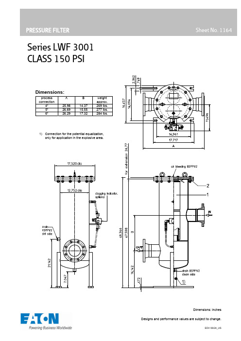
Series LWF 3001CLASS 150 PSIinchesDimensions:Pressure filterSeries LWF 3001CLASS 150 PSIDescription:In-line filters of the series LWF 3001 have a working pressure up to 232 PSI. Pressure peaks can be absorbed with a sufficient safety margin. The filters can be installed as suction filter, pressure filter or return-line filter.The filter element consists of star-shaped, pleated filter material, which is supported on the inside by a perforated core tube and is bonded to the end caps with a high-quality adhesive. The flow direction is from outside to inside.For cleaning the stainless steel mesh element or changing the microglass element, remove the cover and take out the element. The mesh elements are not guaranteed to maintain 100% performance after cleaningFor filtration finer than 25 μm, use the disposable elements made of microglass. Filter elements as fine as 3 μm are available; finer filter elements are available upon request.Eaton filter elements are known for high intrinsic stability and an excellent filtration capability, a high dirt-retaining capacity and a long service life.Eaton filter are suitable for all petroleum based fluids, HW-emulsions, most synthetic hydraulic fluids and lubrication oils.Ship classifications available upon request. Type index:Complete filter: (ordering example)LWF. 3001. 10VG. 10. E. P. -. FA11. C. -. -.1 2 3 45678 91011 KH. OE12 131 series:LWF = in-line welded filter2 nominal size: 30013 filter material:80G, 40G, 25G, 10G stainless steel wire mesh25VG, 16VG, 10VG, 6VG, 3VG microglass25API, 10API microglass according to API4 filter element collapse rating:10=∆p 145 PSI5 filter element design:E =withoutby-passS =with by-pass valve ∆p 29 PSI6 sealing material:P =Nitrile(NBR)V =Viton(FPM)7 filter element specification:- =standardVA=stainlesssteelIS06 = for HFC application, see sheet-no. 316018 process connection:FA11 =flange ANSI CLASS 150 PSI,sealing surface rough grind 1600-3600 μinFA12 =flange ANSI CLASS 150 PSI,sealing surface rough grind < 640 μin9 process connection size:B =4“C =5“standardD =6“10 filter housing specification:- =standard11 specification pressure vessel:- =standard(PED2014/68/EU)IS20 = ASME VIII Div.1 with ASME equivalent material,see sheet-no. 55217 (operating pressure 145 PSI)12 shut-off:- =withoutKH = with shut-off ball valve13 clogging indicator or clogging sensor:- =withoutAE = visual-electrical, see sheet-no. 1609OP = visual, see sheet-no. 1614OE = visual-electrical, see sheet-no. 1614VS5 = electronic, see sheet-no. 1641VS6 = electronic, see sheet-no. 1643Filter element: (ordering example)01E. 1501. 10VG. 10. E. P. -1 2 3 4 5 6 71 series:01E = filter element according to company standard2 nominal size: 15013 - 7 see type index-complete filterAccessories:- drain- and bleeder connection, see sheet-no. 1651- lifting mechanism, see sheet-no. 1662Technical data:operating temperature: +14°F to +212°Foperating medium: mineral oil, other media on requestmax. operating pressure: 232 PSItest pressure: 333 PSIprocess connection: flange ANSI B16.5 CLASS 150 PSIhousing material: carbon steelsealing material: Nitrile (NBR) or Viton (FPM), other materials on requestinstallation position: verticaldrain- and bleeder connections: BSPP ½measure connections: BSPP ¼volume tank: 21 Gal.Classified under the Pressure Equipment Directive 2014/68/EU for mineral oil (fluid group 2), Article 4, Para. 3.Classified under ATEX Directive 2014/34/EU according to specific application (see questionnaire sheet-no. 34279).Pressure drop flow curves:Filter calculation/sizingThe pressure drop of the assembly at a given flow rate Q is the sum of the housing ∆p and the element ∆p and is calculated as follows:∆p assembly= ∆p housing+ ∆p element∆p housing = (see ∆p= f (Q) - characteristics)For ease of calculation, our Filter Selection tool is available online at: /hydraulic-filter-evaluationMaterial gradient coefficients (MSK) for filter elementsThe material gradient coefficients in psi/gpm apply to mineral oil (HLP) with a density of 0.876 kg/dm³ and a kinematic viscosity of139 SUS (30 mm²/s). The pressure drop changes proportionally to the change in kinematic viscosity and density.LWF VG G API 3VG 6VG 10VG 16VG 25VG 10G 25G 40G 80G 10 API 25 API0.0025 0.0017 0.024 0.0110.00263001 0.096 0.067 0.043 0,037 0.0250.0035∆p=f(Q) – characteristic according ISO 3968The pressure drop characteristics apply to mineral oil (HLP) with a density of 0,876 kg/dm³. The pressure drop changes proportionallyto the density. The flow curves for 4” and 6” available on request.Symbols:without indicatorwithshut-off ball valvewith electric indicator AE30/AE40with visual-electric indicator AE50/AE62with visual-electric indicatorAE70/AE80/AE90with visual indicator OPwithvisual-electric indicator OEwith electronic sensor VS5/VS6filter without by-pass valvefilter withby-pass valveSpare parts:item qty. designation dimension artikle-no.1 2 filter element 01E.1501…31O-ring339 x 5352792 (NBR)352793 (FPM)Test methods:Filter elements are tested according to the following ISO standards:ISO 2941 Verification of collapse/burst resistance ISO 2942 Verification of fabrication integrityISO 2943 Verification of material compatibility with fluids ISO 3723 Method for end load testISO 3724 Verification of flow fatigue characteristicsISO 3968 Evaluation of pressure drop versus flow characteristics ISO 16889Multi-pass method for evaluating filtration performanceNorth America18684 Lake Drive East Chanhassen, MN 55317 Toll Free: +1 800-656-3344 (North America only) Tel: +1 732-212-4700Europe/Africa/Middle East Auf der Heide 253947 Nettersheim, Germany Tel: +49 2486 809-0 Friedensstraße 4168804 Altlußheim, Germany Tel: +49 6205 2094-0An den Nahewiesen 2455450 Langenlonsheim, Germany Tel: +49 6704 204-0Greater China No. 7, Lane 280, Linhong RoadChangning District, 200335 Shanghai, P.R. China Tel: +86 21 2899-3687Asia-Pacific100G Pasir Panjang Road #07-08 Interlocal Centre Singapore 118523 Tel: +65 6825-1620For more information, please email us at ********************or visit /filtration© 2024 Eaton. All rights reserved. All trademarks and registered trademarks are the property of their respective owners. All information and recommendations appearing in this brochure concerning the use of products described herein are based on tests believed to be reliable. However, it is the user’s responsibility to determine the suitability for his own use of such products. Since the actual use by others is beyond our control, no guarantee, expressed or implied, is made by Eaton as to the effects of such use or the results to be obtained. Eaton assumes no liability arising out of the use by others of such products. Nor is the information herein to be construed as absolutely complete, since additional information may be necessary or desirable when particular or exceptional conditions or circumstances exist or because of applicable laws or government regulations.。
“互联网+”时代下视觉传达设计专业教学改革研究

高等美术教育036 / INDUSTRIAL DESIGN 工业设计“互联网+”时代下视觉传达设计专业教学改革研究RESEARCH ON THE TEACHING REFORM OF VISUAL COMMUNICATION DESIGN MAJORIN THE "INTERNET+" ERA北京理工大学珠海学院 王宇 李金泽利用信息和互联网平台,使互联网与传统产业融合,以外也可以利用互联网的优势和特点,为高校专业教学创造新的机遇。
2视觉传达设计专业教学现状在当前的视觉传达专业教学中,存在着很多的问题,影响和制约着视觉传达设计专业的发展,主要包括以下内容:2.1一成不变的培养计划与目标在人才培养方案的制定中,一些学校和教师没有注意到学生能力的差异性,导致人才培养计划与学生实际能力脱节。
且视觉传达设计专业尚未开设与其他艺术设计方向相关的课程,以及与视觉传达设计专业的交叉课程。
在人才培养目标方面,对学生培养能力的相关内容要求相对模糊。
传统视觉传达专业的培养目标以能适应社会主义现代市场经济建设,适应创新时代的需求,具备扎实的设计基础,掌握各项视觉传达设计技能,能在各行业的企划部门、设计部门、广告公司、设计公司中从事视觉传达设计、策划工作的专门人才[1]。
2.2传统且单一的教学方法在视觉传达设计专业的教学中,教师讲授的理论知识具有概括性、抽象性的特点,让人难以理解,忽视了学生的学习情况和学习需求,教学方式单一。
采用“填鸭式”的教学方法,学生以惯性状态听课,不主动参与课堂教学,长久下去必将不利于教学活动的展开。
2.3有限而陈旧的教学资源教师在教学环节中通常仅仅用课件、以往学生作业、教程的案例,学生们了解的多数是视觉设计的类型、艺术形式、设计理念和设计知识,无法真正地获取有效资源并得到训练,因而,有限而陈旧的教学资源降低了视觉传达专业的教学效果[2]。
教师应该让学生们的知识储备、思维逻辑、专业技能更加全面和综合,这样才能够设计出更多优秀的作品[3]。
社区营造理论下的社区公共空间微更新设计——以上海市斜土街道为例

摘要:社区作为构建城市的基本单位,是城市更新进程中必不可少的重要环节,社区微更新中的精神内涵与品质提升成为备受关注的话题。
文章运用社区营造理论,从人本维度,管理维度,文化维度三个维度出发,对社区公共空间微更新设计原则与策略进行研究,并以上海市斜土街道中的典型社区为例,针对性地提出微更新设计策略,为实现自组织、自治理、自发展的社区发展模式提供借鉴意义。
关键词:社区公共空间 微更新 社区营造 公众参与 上海斜土街道 中图分类号:TU984.11+3 文献标识码:A 文章编号:1003-0069(2023)13-0036-04Abstract:As the basic unit of urban construction,community is anindispensable and important link in the process of urban renewal. The spiritual connotation and quality improvement have become a topic of great concern. This article uses the theory of community revitalization,starting from the three dimensions of the person's standard,management dimension,and cultural dimension,researching the design principles and strategies of the community public space micro-update.Taking the typical community in Xietu Street in Shanghai as an example,the micro-renewal design strategy is put forward in a targeted manner to provide reference for the realization of a community development model of self-organization,self-governance,and self-development.Keywords:Ommunity public space Micro-renewal Community revitalization Public participation Xietu street in Shanghai上海理工大学出版印刷与艺术设计学院 章丹音 张 琰社区营造理论下的社区公共空间微更新设计——以上海市斜土街道为例MICRO-RENEWAL DESIGN OF COMMUNITY PUBLIC SPACE BASED ON COMMUNITY REVITALIZATION:TAKING XIETU STREET IN SHANGHAI AS AN EXAMPLE引言党的十九大报告中提出,要“加强社区治理体系建设”,打造“共建共享公治的社会治理格局”。
基于音圈电机的电梯水平振动主动控制仿真

基于音圈电机的电梯水平振动主动控制仿真宋春涛;黄震宇【摘要】电梯运行中导轨不平引起的水平振动会影响舒适性.为了有效抑制电梯振动,以音圈电机为作动器,使用振动主动控制,建立音圈电机和电梯水平振动的数学模型.布置传感器和作动器的位置,将位移、速度和加速度的比例反馈组合为PID控制器,使用Matlab/Simulink对控制器进行参数整定;并对电梯水平振动主动控制系统进行仿真分析.仿真结果表明在共振频率处的振动位移得到大幅抑制,同时随机振动激励下的振动位移有明显减小.【期刊名称】《科学技术与工程》【年(卷),期】2014(014)026【总页数】4页(P228-231)【关键词】音圈电机;电梯;水平振动;主动控制【作者】宋春涛;黄震宇【作者单位】上海交通大学电子信息与电气工程学院仪器科学与工程系,上海200240;上海交通大学电子信息与电气工程学院仪器科学与工程系,上海200240【正文语种】中文【中图分类】TH211.7电梯运行中导轨的不平导致电梯发生水平方向振动,影响电梯乘员的舒适度。
被动控制对振动的抑制能力有限,为了进一步降低振动,振动主动控制的应用日趋广泛[1,2]。
本文使用音圈电机作为作动器,使用PID 控制策略,通过建模和仿真,对音圈电机在电梯水平振动控制中的应用进行研究。
1 音圈电机模型音圈电机是一种直线电机,具有体积小、重量轻、响应快、推力均匀的特点,被广泛地用于精密位置控制、伺服驱动以及振动主动控制中[3](图1)。
图1 音圈电机结构Fig.1 Structure of voice coil motor直线型音圈电机的定子是永磁体,动子是线圈,定子产生恒定磁场,线圈通电后受力,在磁场中沿直线运动[4]。
音圈电机气隙中的磁场以轴线为中心呈放射形,由一定匝数绕成的线圈位于磁场中,线圈上在磁场中的部分受力均匀,定子和动子在力的作用下发生相对位移(图2)。
图2 音圈电机模型Fig.2 Model of voice coil motor根据通电导体在磁场中的受力F=Bli,可以根据上图推导出通电线圈在磁场中的受力:式(1)中,FA为音圈电机的出力;r 为线圈的半径;N 为线圈匝数;B 为磁感应强度;i 为线圈中的电流;ki为电流常数。
- 1、下载文档前请自行甄别文档内容的完整性,平台不提供额外的编辑、内容补充、找答案等附加服务。
- 2、"仅部分预览"的文档,不可在线预览部分如存在完整性等问题,可反馈申请退款(可完整预览的文档不适用该条件!)。
- 3、如文档侵犯您的权益,请联系客服反馈,我们会尽快为您处理(人工客服工作时间:9:00-18:30)。
Design-1TitleDesign of Beam with Compression Reinforcement(notes on ACI318-02, Example 6.2)DescriptionA beam cross-section is limited to the size shown. Determine the required area of reinforcement for a factored moment u M = 516 ft-kips (6,192 in-kips). 'c f =4,000 psi, =60,000 psi. y fStructural geometry and analysis model1Verification ExampleResults by the ACI318-02Check if compression reinforcenment is required, using φ = 0.9/516/0.9573n u M M φ===ft-kips (6,876 in-kips) 22/573121,000/1420.51,169n n R M bd ==×××=The maximumu R nt for tension-controlled sections of 4,000 psi concrete : R nt = 911Find the normal strength moment nt M resisted by the concrete section without compression reinforcement, and 'n M to be resisted by the compression reinforcement.229111420.5/(1,00012)447nt n M R bd ×××==='ft-kips (5,364 in-kips)n M 573447126n nt M M −−===ft-kips (1,512 in-kips)Compression reinforcement 'sAin 2 Tension reinforcement s A's===''()(/)0.01806(14)(20.5) 1.43(58.7/60) 6.58 s t s s y bd A f f A ρ++=== in 2'''12612 1.4358.7(50.2 2.5)()n s M A f d d ×−−Reinforcement PatternTop 2-#8 (1.58 in 2) Bottom9-#8 (7.11 in 2)2Design-1Results by MIDAS/Gen------------------------------------------------------------------------MIDAS/Gen - RC-Beam Checking [ ACI318-02 ]=========================================*.MIDAS/Gen – RC-BEAM Analysis/Design Program.*.DESIGN CODE : ACI318-02, *.UNIT SYSTEM : kip, in*.DESCRIPTION OF BEAM DATA (iSEC = 1) : sectSection Type : Rectangle (RECT)Beam Length (Span) = 200,000 inSection Depth (H c) = 23,000 inSection Width (B c) = 14,000 inConcrete Strength (f c) = 4,000 kip/in2Main Rebar Strength (f y) = 60,000 kip/in2Stirrups Strength (f ys) = 60,000 kip/in2Modulus of Elasticity (E s) = 29000,000 kip/in2*.FORCES AND MOMENTS AT CHECK POINT <1> :Positive Bending Moment P-M u= 6192.00 kip-in., LCB = 1Shear Force V u= 34.51 kip. , LCB = 1*.REINFORCEMENT PATTERN :---------------------------------------------------------Location i di( in.) Rebar Asi( in^2.)---------------------------------------------------------Top 1 2.500 2-#8 1.58000Bottom 2 20.500 9-#8 7.11000---------------------------------------------------------Stirrups : #3====================================================[[[*]]] ANALYZE POSITIVE BENDING MOMENT CAPACITY.====================================================( ). Compute design parameter (beta1).-. beta1 = 0.8500 ( fc < 4000 psi.)( ). Compute required ratio of reinforcement.-. Rhomi1 = MAX[ 3*SQRT[fc]/fy, 200/fy ] = 0.0033-. Rhomi2 = (4/3)*Mu/[ fy*b*d1*(d1-a/2) ] = 0.0333-. Rhomin = MIN[ Rhomi1, Rhomi2 ] = 0.00333Verification Example-. Rho_et = 0.85*beta1*(fc/fy)*(0.003/(0.003+0.004)) = 0.0206-. Rhomax = Rho_et = 0.0206( ). Check ratio of tensile reinforcement.-. Rho = As/(bw*d) = 0.0248-. Rho > Rhomax ---> Not Acceptable !!!( ). Check maximum permissible tensile reinforcement.-. cb = (0.003/(0.003+0.004))*d1 = 8.786 in.-. c_max = cb = 8.786 in.-. a_max = beta1*c_max = 7.468 in.-. Cc_max = 0.85*fc*(bw*a_max) = 355.47 kip.-. es2 = 0.003*(c_max-d2)/c_max = 0.002-. fs2 = Es*es2 = 60.000 kip/in^2.-. Cs = (fs2-0.85*fc)*As2 = 89.43 kip.-. Ts_max = Cc_max+Cs = 444.90 kip.-. Asmax = Ts_max/fy = 7.415 in^2.-. As1 = 7.110 in^2. < Asmax ---> O.K !( ). Check compression steel yield condition.-. cy = (0.003/(0.003-fy/Es))*d2 = 8.056 in.-. Ccy = 0.85*fc*bw*(beta1*cy) = 325.93 kip.-. Csy = (fy-0.85*fc)*As2 = 89.43 kip.-. Tsy = Ccy+Csy = 415.36 kip.-. Asy = Tsy/fy = 6.923 in^2.-. As1 = 7.110 in^2. > Asy ---> Compression steel yield.( ). Compute moment capacity.-. Ts = As1*fy = 426.60 kip.-. Cs = (fy-0.85*fc)*As2 = 89.43 kip.-. Cc = Ts-Cs = 337.17 kip.-. a = Cc/(0.85*fc*bw) = 7.083 in.-. Mn = Cc*(d1-a/2)+Cs*(d1-d2) = 7327.56 kip-in.-. phi = 0.90-. phiMn = phi*Mn = 6594.80 kip-in.( ). Check ratio of positive moment capacity.-. Rat_P = Mu/phiMn = 0.939 < 1.000 ---> O.K.4Design-15Verification ExampleComparison of ResultsMIDAS/Gen ACI318-02Top 2-#8 (1.58 in2) 2-#8 (1.58 in2)Bottom 9-#8 (7.11 in2) 9-#8 (7.11 in2)6。
