CC0402KRX7R9BB103中文资料
LED49-55M5600UC维修手册
-4–
端子图:
内部技术资料,注意保密!
-5–
(二)、产品功能规格、特点介绍:
内部技术资料,注意保密!
HDMI、分量输入端口支持的信号格式:
(三)、产品差异介绍
LED49M5600UC 200778 液晶屏\HE490IUC-E31\S0 201305 主板组件\RSAG2.908.6935-02\ROH
删除 1040 1043880 片式电阻\RC0402JR-07-0R0\TP\ROH 1 EA R476 无
-2–
内部技术资料,注意保密!
F、故障板的常规判断方法 ............................................................. 64
-3–
内部技术资料,注意保密!
液晶电视服务手册
LED49M5600UC、LED55M5600UC
一、产品介绍 (一)、产品外观介绍
-7–
196405 电源板组件\RSAG2.908.6905-01\ROH
LED55M5600UC 200955 液晶屏\HE550IUC-B52 197124 主板组件\RSAG2.908.6935\ROH 198571 电源板组件\RSAG2.908.6570-03\ROH
内部技术资料,注意保密!
R
多媒体产品维修手册
LED49M5600UC、LED55M5600UC
主板方案:MSD6A826 电源方案:HLL-4960WB(49 尺寸)
HLL-4655WQ(55 尺寸)
多媒体研发中心 2016.6
内部技术资料,注意保密!
目
录
LED49M5600UC、LED55M5600UC ....
电容CHIP识别教育资料

三星电容:
CL 10 A 105 K Q 8 N N N C ① ② ③ ④ ⑤ ⑥ ⑦⑧ ⑨ ⑩ ⑾
京瓷(KYOCERA)电容: CM 21 X7R 105 K 10 A T 000 ① ② ③ ④ ⑤⑥⑦⑾ ⒀
村田(MuRata)电容: GRM 36 X7R 472 K 25 PT
TDK电容:
① ② ③ ④ ⑤ ⑥⑾ C 1005 COG 1E 100 D T ① ② ③ ⑥ ④ ⑤⑾
国巨(YAGEO)电容:
CC 0603 K R X7R 9 B B 102
① ② ⑤ ⑾ ③⑥⑧⑿④
①:表示系列编号
※ ②:表示元器件尺寸编码 ※ ③:表示元器件温度特性 (电解质编码)
※ ④:表示元器件的值编码 ※ ⑤:表示元器件值允许误差编码
以上序号根据命名代号顺序
村田( MuRata )电容简介
4. 额定容量: 容量大小一般由三位数字表示,前二位表 示容量的有效值,第三位数字表示10的乘方(即0的个 数),容量单位为PFຫໍສະໝຸດ ※ ⑥:表示元器额定电压编码
⑦:表示元器件终端类型编码
⑧:表示内电极/端子/电镀编码 ⑨:表示产品编码
⑩:表示特殊编码
⑾:表示包装编码
※ ⑿:表示B = 卑金属电极,N = 非卑金属电极(卑金属便宜的金属,非卑指贵金属)。
⒀:选用品-特殊情况的选用
国巨(YAGEO)电容简介
国巨积层陶瓷电容(MLCC)包括一般陶瓷电容、高容值陶瓷电容、软端电极电容、 串连排容、中高压电容、低感值电容、高频电容和X2Y®电容滤波器。国巨积层陶瓷 电容(MLCC)型号包括9个部分,下面以CC0603KRX7R9BB102为例 ①表示国巨积层陶瓷电容的系列名称。CC表示一般的贴片电容,CS表示软端电极电 容,CA表示串连排容,CH表示高频电容,CL表示低感值电容,CX表示X2Y®电容滤波 器。 ②表示标准EIA晶片尺寸。国巨电容的常用尺寸有0201,0402,0603,0805,1206, 1210,1808,1812,2010,2512等。 ⑤表示电容误差值。 A=±0.05PF,B=±0.1PF,C=±0.25PF,D=±0.5PF,F=±1PF,G=±2PF,J=±5%,K=±10%,M=±2 0%,Z=-20%~+80%。 ⑾表示包装形式。R表示7寸盘纸带卷装,P表示8寸盘纸带卷装,K表示7寸盘塑料带 卷装。 ③表示介电材料。国巨陶瓷电容介电材料有NPO,X5R,X7R,Y5V。 ⑥表示电压。4=4V, 5=6.3V, 6=10V, 7=16V, 8=25V, 0=100V, A=200V, B=500V, C=1KV, D=2KV, E=3KV等。 ⑧表示引脚材料。A = PdAg,B = Ni-Barrier,C = Ni / Au。 ⑿ B = 卑金属电极,N = 非卑金属电极。 ④表示容值。有效数字+零号码,第三位是指数。如果容值带有小数点,用R表示小 数点。如5.6PF=5R6,100=10PF,101=100PF, 102=1000PF, 103=10,000PF……以此类推。
电子元器件采购项目基本情况表

12
38
接插件
HDR-TH_6P-P2.54-H-M-W'10.0
DIP
20
39
集成电路
BKW0805UC3N3KGT
SOP
20
40
集成电路
V1CF5020T-4R7N1R7-1
SOP
10
41
集成电路
B1M15AX601SN1D
10402
50
42
集成电路
TR0402D10K0Q1025Z
R0402
R0402
50
71
电阻
RMC060333.2K1%N
R0603
100
72
接插件
TS665CJ
DIP
50
73
集成电路
HMC7331C4BTR-R5
SOP
6
74
集成电路
AVA-24A+
QFN
6
75
集成电路
ADA4625-IARDZ
SOIC
6
76
集成电路
EP2-19+
QFN
5
77
集成电路
P42BN1820M5S
C0805
100
22
电容
CC0402KRX7R9BB473
C0402
100
23
电容
C121A475KBQNNNE
C0805
100
24
电容
CC0402FRNP09BN121
C0402
100
25
电容
GRM155R6YA225KE11D
C0402
100
26
电容
海信LCD、PDP、CRT、IC、主板及电源板替代方案汇总-至121013

15
TLM42V68PK(0)(2)
RSAG7.820.1859
RSAG2.908.1642-5
122987
RSAG2.908.1642-1
16
TLM26E29(2)(5)(6)
RSAG7.820.1441
RSAG2.908.1321-4
117960 RSAG2.908.1321-1
17
TLM37V86K(0)
RSAG7.820.1672
RSAG2.908.1499-18
124969 RSAG2.908.1499-11
TLM26E29X(8)(9)
18
TLM26E29(8)(9)
LED42T18GPN(0)
RSAG7.820.1796
RSAG2.908.1595
120561
RSAG2.908.1595-1
113641
113641
119704
116692 119412
122584
120026
122681
122982
117703
122508
直接替代 在1438-15板子上做以下更改: 1、将C255片式瓷介106更改为1038246 片式瓷介\225 2、R289跨接线改为\1026752 片式电阻\RC0603JR-07-10K 在1642-1板子上做以下更改: 1、 将XP15插座1028546 插座\TJC10-4A更改为: 2、 R235更改为跨接线 3、 R263\R264\R855\R856更改为:1043871\片式电阻\RC0402 JR-07-33R 4、 R238更改为跨接线 5、 R269 \R271\ R858\R859更改为:1043877 片式电阻\RC0402 JR-07-68R 6、 R260更改为:1031430片式电阻\RC0603JR-07-2K4 7、 R530更改为 1026785 片式电阻\RC0603JR-07-2K2 8、 增加Z40 Z41 1026696片式瓷介CC0603KRX7R9BB103 在1321-1板子上做以下更改: 在1321-1板子上做以下更改: 将R413 R414 改为1026755 片式电阻\RC0603JR-07-12K 在1499-11板子上做以下更改: 1、去掉R391跨接线,改为R392跨接线 2、去掉RD7\1053148 片式电阻\RC0402JR-07-100R 3、将UD1更改为1065375 片式电路\EM6AA160TSA-4G\JP\JK\ROH (将原板子上的UD1移到 新板) 在1595-1板子上做以下更改: 1、将N8片式电路\MST9U19E-LF\JK拆下,用原板子上的N8片式电路\MST9U19B-LF\JK替代 。 2将N17片式电路\TDA9885TS\TP\GC拆下,用原板子上的N17片式电路\TDA9885TS\TP\JK替 代。
0402YC103KAT2A,0402YC103KAT2A,0402YC103KAT2A,04025C102KAT2A,04025C102KAT2A,, 规格书,Datasheet 资料
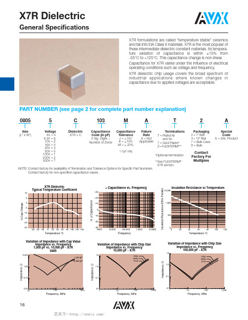
PART NUMBER (see page 2 for complete part number explanation)
0805
Size (L" x W")
5
Voltage 4V = 4 6.3V = 6 10V = Z 16V = Y 25V = 3 50V = 5 100V = 1 200V = 2 500V = 7
T
Terminations T = Plated Ni and Sn 7 = Gold Plated* Z= FLEXITERM®**
2
Packaging 2 = 7" Reel 4 = 13" Reel 7 = Bulk Cass. 9 = Bulk
A
Special Code A = Std. Product
10 1206 0805 1210
Impedance,
Impedance,
1.00
1.0
Impedance,
1.0
0.10
0.1
0.1
0.01 10
100
1000
.01 1 10
.01 100 1,000 1 10
100
1,000
Frequency, MHz
Frequency, MHz
Frequency, MHz
Insulation Resistance (Ohm-Farads)
X7R Dielectric Typical Temperature Coefficient
10 5
Capacitance vs. Frequency
+30 +20
Insulation Resistance vs Temperature
MTK6260儿童定位电话手表原理图

U2-A
CMDAT7 CMDAT6 CMDAT5 CMDAT4 CMDAT3 CMDAT2 CMDAT1 CMDAT0 CMPDN
CMRST
CMPCLK CMMCLK
UART
C
P19 T17 U18 T16 T18 U17 R17
MSDC
CAMERA
CMVREF CMHREF
KEY
UTXD1 URXD1 UTXD2 URXD2 B10 C11 B11 A11 R205 4.7K UTXD1 URXD1 UTXD2 URXD2 [7] [7] [8] [8] VIO28
VCORE VIO18 VIO28 VSF VRF VA
C301 VCORE VIO28 VMC C305 2.2uF GND_SIGNAL 1uF GND_SIGNAL
U9 M3 E3
VBAT_DIGITAL VBAT_SPK VBAT_VA
POWER IN
C
C
VCAMA VMC VUSB VSIM1 BACKUP C316 1uF R316 1.5K C399 1uF GND_SIGNAL J301 C321 1uF GND_SIGNAL C314 1uF GND_SIGNAL VBAT 1 C315 4.7uF GND_SIGNAL 2 + -
T19 P18 R19 N16 P17 N17 R18 J16 H18
SOUT SFCS0 SIN SCK SHOLD SWP SFCS1 LSCE1_B LSRSTB LPTE LPA0 LRD_B LWR_B LPCE0_B LPCE1_B LPRSTB NLD0 NLD1 NLD2 NLD3 NLD4 NLD5 NLD6 NLD7 NLD8
国巨积层陶瓷电容型号命名
⑨表示容值。有效数字+零号码,第三位是指数。如果容值带有小数点,用R表示小数点。如5.6PF=5R6,100=10PF,101=100PF, 102=1000PF, 103=10,000PF……以此类推。
③表示电容误差值。A=±0.05PF,B=±0.1PF,C=±0.25PF,D=±0.5PF,F=±1PF,G=±2PF,J=±5%,K=±10%,M=±20%,Z=-20%~+80%。
④表示包装形式。R表示7寸盘纸带卷装,P表示8寸盘纸带卷装,K表示7寸盘塑料带卷装。
⑤表示介电材料。国巨陶瓷电容介电材料有NPO,X5R,X7R,Y5V。
⑥表示电压。4=4V, 5=6.3V, 6=10V, 7=16V, 8=25V, 0=100V, A=200V, B=500V, C=1KV, D=2KV, E=3KV等。
⑦表示引脚材料。A = PdAg,B = Ni-Barrier,C = Ni / Au。
⑧B = 卑金属电极,N = 非卑金属电极。
国巨积层陶瓷电容型号命名 Nhomakorabea国巨积层陶瓷电容(MLCC)包括一般陶瓷电容、高容值陶瓷电容、软端电极电容、串连排容、中高压电容、低感值电容、高频电容和X2Y?电容滤波器。国巨积层陶瓷电容(MLCC)型号包括9个部分,下面以CC0603KRX7R9BB102为例
CC 0603 K R X7R 9 B B 102
① ② ③ ④ ⑤ ⑥ ⑦ ⑧ ⑨
①表示国巨积层陶瓷电容的系列名称。CC表示一般的贴片电容,CS表示软端电极电容,CA表示串连排容,CH表示高频电容,CL表示低感值电容,CX表示X2Y?电容滤波器。
②表示标准EIA晶片尺寸。国巨电容的常用尺寸有0201,0402,0603,0805,1206,1210,1808,1812,2010,2512等。
EXCEL比较工具试用版
MAIN MAIN MAIN MAIN MAIN MAIN MAIN MAIN MAIN MAIN MAIN MAIN MAIN MAIN MAIN MAIN MAIN
MAIN MAIN MAIN MAIN MAIN MAIN MAIN MAIN MAIN MAIN MAIN MAIN MAIN MAIN MAIN MAIN MAIN MAIN MAIN
MAIN
MAIN
SUB SUB
MAIN
SUB
SUB MAIN SUB SUB
MAIN SUB
SUB MAIN
SUB SUB MAIN
SUB
SUB
MAIN SUB MAIN MAIN SUB SUB SUB SUB MAIN MAIN MAIN MAIN SUB MAIN SUB SUB MAIN MAIN MAIN
MAIN SUB MAIN MAIN SUB MAIN
MAIN
WRN:替代料和主料位号不一致,可能是配置表省略替代物料处理WRN:替代料和主料位号不一致,可能是配置表省略替代物料处理
WRN:替代料和主料位号不一致,可能是配置表省略替代物料处理WRN:替代料和主料位号不一致,可能是配置表省略替代物料处理
WRN:替代料和主料位号不一致,可能是配置表省略替代物料处理。
各种贴片电容容值规格参数表

各种贴片电容容值表X7R贴片电容简述X7R贴片电容属于EIA规定的Class 2类材料的电容。
它的容量相对稳定。
X7R贴片电容特性具有较高的电容量稳定性,在-55℃~125℃工作温度范围内,温度特性为±15%。
层叠独石结构,具有高可靠性。
优良的焊接性和和耐焊性,适用于回流炉和波峰焊。
应用于隔直、耦合、旁路、鉴频等电路中。
X7R贴片电容容量范围厚度与符号对应表符号A C E G J K M N P Q X Y Z最大厚度毫米(英寸)0201~1206 X7R贴片电容选型表封装尺020040060080120125112*********工作电2011125102050100A150A220330AJJJKJCGGJJ470ACGGJJJJJJK680电容(pFGGJJJJJJC1000AK1500CGGJJJJJJJJJJJJM2200GGJJJJJCCJJJJJJ3300JMCGJJJJJJJ4700JJJJJMJ JG J J J J CC P6800 J J J J J JJ J J J J J J G J J J CJ J PC G G J J J J J J J J J J J MC G MJ JJJJ J J J JJ MJ G M 电容量 J J J J J J J J MG G (uF)J J J J M J J J J J MJJJ J J G JJ J PJG G GJ J J J J J J J MJ J J J J J J GG J J M J J J JJ J M M M MN M M M MN M MQ M N MPQ1625501016255010010162550工作电压 1610020010162550100200500 0603080512060201封装尺寸04021210~2225 X7R贴片电容选型表封装尺121181182222222 1125102050510205051051020工作电510 10001500JJJJJJM2200电容(pF3300JJJJJJM4700JJJJJJM6800JJJJJJMKKKKMMXXXXMPJJJJJJPKKKPMMXXXXMPJJJJJJKKKXMMXXXXMPJJJJJJKKKZMMXXXXMPJJJJJMKKKMMXXXXMPJJJJMKKPMMXXXXMP电容(uFMJJZMKMPXXXMJJMMMMZKPMMXXXMPZMMMXZPNNXPNNMMXQZ1010162550工作电压 100200500501002005005010050100200501002225 封装尺寸1825181212102220NPO COG 贴片电容容量规格表默认分类 2009-07-15 16:28 阅读354 评论1字号:大大中中小小NPO贴片电容简述NPO(COG)贴片电容属于Class 1温度补偿型电容。
Vendor Survey供应商质量管理统计表
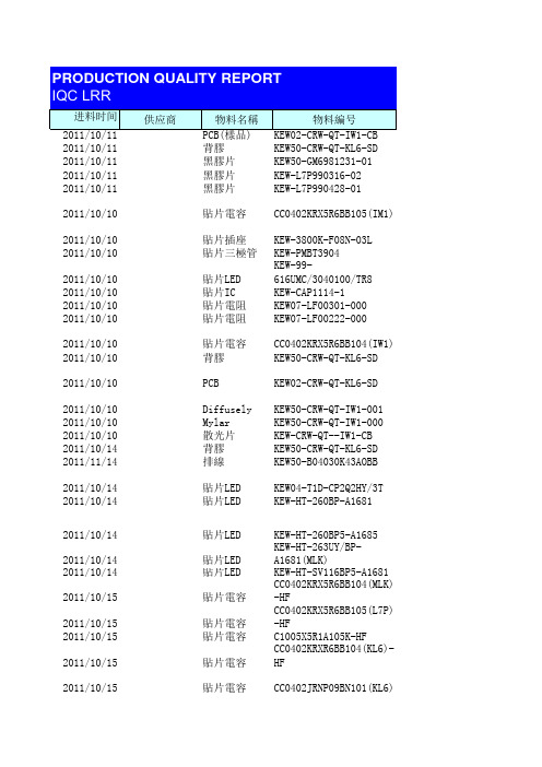
2011-10-11背膠KEW50-CRW-QT-KL6-SD2011-10-11黑膠片KEW50-GM6981231-012011-10-11黑膠片KEW-L7P990316-022011-10-11黑膠片KEW-L7P990428-012011-10-10貼片電容CC0402KRX5R6BB105(IM1) 2011-10-10貼片插座KEW-3800K-F08N-03L2011-10-10貼片三極管KEW-PMBT39042011-10-10貼片LED KEW-99-616UMC/3040100/TR8 2011-10-10貼片IC KEW-CAP1114-12011-10-10貼片電阻KEW07-LF00301-0002011-10-10貼片電阻KEW07-LF00222-0002011-10-10貼片電容CC0402KRX5R6BB104(IW1) 2011-10-10背膠KEW50-CRW-QT-KL6-SD2011-10-10PCB KEW02-CRW-QT-KL6-SD2011-10-10Diffusely KEW50-CRW-QT-IW1-001 2011-10-10Mylar KEW50-CRW-QT-IW1-000 2011-10-10散光片KEW-CRW-QT--IW1-CB2011-10-14背膠KEW50-CRW-QT-KL6-SD2011-11-14排線KEW50-B04030K43AOBB2011-10-14貼片LED KEW04-T1D-CP2Q2HY/3T 2011-10-14貼片LED KEW-HT-260BP-A16812011-10-14貼片LED KEW-HT-260BP5-A16852011-10-14貼片LED KEW-HT-263UY/BP-A1681(MLK 2011-10-14貼片LED KEW-HT-SV116BP5-A1681 2011-10-15貼片電容CC0402KRX5R6BB104(MLK)-HF 2011-10-15貼片電容CC0402KRX5R6BB105(L7P)-HF 2011-10-15貼片電容C1005X5R1A105K-HF2011-10-15貼片電容CC0402KRXR6BB104(KL6)-HF 2011-10-15貼片電容CC0402JRNP09BN101(KL6) 2011-10-15貼片電容CC0402KRX5R6BB105(MLK)-HF 2011-10-15貼片電容CC0402JRNP09BN101(MLK) 2011-10-15貼片電阻RC0402JR-07270R(MLK)-HF 2011-10-15貼片電阻RC0402JR-07100RL(KL6) 2011-10-15貼片電阻RC04023JR-0710K(MLK) 2011-10-15貼片電阻RC0402JR-07330R(L7P) 2011-10-15貼片電阻RC0402JR-0710L(KL6)-HF 2011-10-15貼片電阻RC0603JR-070R(MLK)2011-10-15貼片電阻RC0402JR-07100RL(MLK) 2011-10-15貼片二極管KEW-SCS751V-TG-WS2011-10-15貼片三極管KEW-2N7002K-001(MLK) 2011-10-14貼片突破器KEW-TVMOG5R5M411R2011-10-15貼片IC KEW01-1T7230BFN-BX-001(KL2011-10-16貼片插座KEW-196033-120412011-10-14貼片IC KEW01-1T7230BFN-BX-001(ML 2011-10-15貼片開關NTC017-DA1J-D160T2011-10-15貼片IC KEW01-APX9132HAI-TRG 2011-10-17背膠KEW50-GM6990201-012011-10-18PCB KEW02-CRW-QT-KL6-SD2011-10-21PCB KEW02-CRW-QT-GM6-012011-10-22PCB KEW02-CRW-QT-GM6-012011-10-21PCB KEW02-CRW-QT-GM6-012011-10-11PCB(樣品)KEW02-CDK1130-0002011-10-18PCB KEW02-CRW-QT-L7P-SD2011-10-17PCB KEW02-CDK1116-R042011-10-21PCB KEW02-CRW-QT-KL6-SD2011-10-21背膠KEW50-GM69901-012011-10-21黑膠片KEW-L7P990428-012011-10-21黑膠片KEW-L7P990316-022011-10-21貼片插座196353-06021-32011-10-14排線B06105K42C0SD(990309-01) 2011-10-18石英CSTCE12MOG15M99-R02011-10-21膠片KEW-CDK1130-0012011-10-24背膠KEW50-GM699022011-10-24PCB KEW02-CRW-QT-GM6-012011-10-24PCB KEW02-CRW-QT-GM6-012011-10-24PCB KEW02-CRW-QT-GM6-012011-10-24PCB KEW02-CRW-QT-KL6-SD2011-10-24PCB KEW02-CRW-QT-KL6-SD2011-10-24PCB KEW02-CRW-QT-KL6-SD2011-10-25PCB KEW02-CRW-QT-KL6-SD2011-10-24貼片IC W25Q80BLZPIG-HF2011-10-24排線KEW-CDK11311-004-HF2011-10-24排線KEW-CDK1131-005-HF2011-10-24排線KEW-CDK1131-003-HF2011-10-25貼片LED KEW-99-218/B2C-AQ1Q2DY/2C 2011-10-25排線B06105K42C0SD(990309-01) 2011-10-25白膠片KEW50-CRW-QT-VY1-SB-001 2011-10-25背膠KEW50-CRW-QT-VY1-SB-002 2011-10-25背膠KEW50-CRW-QT-LZ3-SB2011-10-25黑膠片KEW50-CRW-LZ3-SB-001 2011-10-24排線KEW-CDK1131-006-HF2011-10-26COF VFS5011BA-510-T2011-10-26貼片石英CSTCE12M0G15M99-R0-HT 2011-10-26PCB(樣品)KEW02-CRW-QT-QU7-SB2011-10-26PCB(樣品)KEW02-CRW-QT-LZ3-SB2011-10-26PCB(樣品)KEW02-CRW-QT-VY1-SB2011-10-26貼片IC W25Q80BLZPIG-HF2011-10-26排線KEW-CDK1116-0032011-10-28貼片開關NTC017-DA1J-D160T2011-10-28貼片LED KEW04-T1D-CP2Q2HY/3T 2011-10-28貼片LED KEW-HT-SV116BP5-A1681 2011-10-28貼片LED KEW01-APX9132HAI-TRG 2011-10-28貼片二極管KEW-SCS751V-TG-WS2011-10-28貼片插座KEW-CI1106M1HR0-LF2011-10-28PCB KEW02-CRW-QT-KL6-SD2011-10-28PCB KEW02-CRW-QT-GM6-012011-10-31貼片LED KEW04-23-21C-T1D-CP2Q2TY-2011-10-31PCB KEW02-CRW-QT-KL6-SD2011-10-31PCB KEW02-CRW-QT-L7P-SD114095.5*12.5MM10,000200 CRW-QT-GM6-0151,000500 16*15.5MM+3M46735,000315 L7P35,000315 1UF +-20% 0402 10V49850 3800K-F08N-03L P1.25MM 8PIN370503904100110555337050 99-616UMC/3040100/TR8TR0REQU Y10100691101WJS-K-R1,400125 CAP1114-1EZK-TR-32PIM30050 300R +-5% 120670080 2.2K +-5% 040235050 100NF +-10% 10V 040250050 95.5*12.5MM20,000315 CRW-QT-KL6-SD1113/1125/113920,072315 CRW-QT-IW1-CB (180.5*12MM)320320 CRW-QT-IW1-CB(157*15MM)392392 180.5*12MM T;0.6MM320320 95.5*12.5MM18,000315 CRW-QT-MLK-SB2011.9.2950,000500 19-113/T1DCP2Q2HY/3T WGITE Y11061536,000500 HT-260BP-A16810CB6P54P1148,000500 HT-260BP5-A1685/A168-10CB4723F11/0CB4Z30F11/0CB4Z30450,000800 HT-263UY/BP-A16810DB6P52812/0DB6P5281148,000500 HT-SV116BP5-A16810DB8G51F0DB8G51F1812,000315 100NF +-10% 10V 04021130150,000500 1UF +-10% 10V 0402113030,000315 1UF +-10% 10V 04021125180,000800 100NF +-10% 10V 04021132270,000800 100PF X7R 50V 0402111890,000500 1UF +-10% 10V 04021130100,000500 100PF X7R 50V 0402111850,000500 270R +-5R 0402111540,000500 100R +-5% 0402111990,000500 10K +-5% 04021128200,000800 330R +-5% 0402112840,000500 10K +-5% 04021128360,000800 0R +-5% 0603112750,000500 100R +-5% 0402111950,000500 SCS751V-TG-WS0711********,000500 2N7002K12104G12751,000500 TVMOG5R5M411R 5.5V0RVR1190186-0070,000500 1T7230BFN-BX-0001A01QWB90,272500196033-1204111.10.0649,500500 1T7230BFN-BX-0001A07F0849,920500 SU1THPUSHBUTTON/NTC017-DA1J-D111076098100,000500 APX9132HA1-TRG PIV8L833,000315 CRW-QT-GM6-0146,423500 CRW-QT-KL6-SD113914020 CRW-QT-GM6-0111429,296200 CRW-QT-GM6-01114213,450315 CRW-QT-GM6-01113470480 CDK1130(210 R02)1138400400 CRW-QT-L7P-SD1137/3458035,140500 CDK1116-R04(133-R04)1122/114210,000200 CRW-QT-KL6-SD113914320 CRW-QT-MLK-SB3,300200 L7P25,10031525,100315 6PIN35050 LL7PB(105MM6/6P.R1A)60V12011.9.3035,000315 RESONATOR 12MHZ1,290125 49.5*9MM350350 CRW-QT-MLK-SB46,423500 CRW-QT-GM6-0111424,250200 CRW-QT-GM6-0111423,000125 CRW-QT-GM6-01114212,500315 CRW-QT-KL6-SD11436,000200 CRW-QT-KL6-SD11392,753125 CRW-QT-KL6-SD114325,000315 CRW-QT-KL6-SD114313,750315 W25Q80BLZP1G40050 FFCC06159B11H0453-NH2011.10.1430050 FFCC06159C11H0454-NH 2011.10-1730050 FFCC06159B11H0452-NH 2011.10.1730050 99-218/B2C-AQ1Q2DY/2C(蘭色)800800 LL7PB(105MM6/6P.R1A)60V12011.10.1925,100315 CRW-QT-VY1-SB180180 CRW-QT-VY1-SB180180 CRW-QT-LZ3-SB140140 CRW-QT-LZ3-SB140140 FFCC106159C11H0455-NH2011.10.1135050 VFS5011BA-510-T FB9KPGR104,306200 12MHZ TMM1808B911,705125 CRW-QT-QU7-SB1143100100 CRW-QT-LZ3-SB1143200200 CRW-QT-VY1-SB1143150150 W25Q80BLZPIG 3.6V SOIC-811301,20080 FFCC06149B11H0301-NH DJ52011.10.251,19580 SW1TH PUSHBUTT0N1109632560,00050019-113/T1DCP2Q2HY/3T WGITE Y11050027,000315 HT-SV116BP5-A1681ODBAE32F11/ODBAE32F12/ODBAE138,000500 APX9132HA1-TRG PN8L827,000315 SCS751V-TG-WS0711********,000500 CI1106M1HR0-LF 6PIN 1MM4949 CRW-QT-KL6-SD11421,882125 CRW-QT-GM6-0111436,230200 23-21C-T1D-CP2Q2TP-2A Y1110092,000125 CRW-QT-KL6-SD114316,750315 CRW-QT-L7P-SD114025,160315PASS00.00%PASS00.00%PASS30.95%有手指印PASS20.63%有手指印PASS00.00%PASS00.00%PASS00.00%PASS00.00%PASS00.00%PASS00.00%PASS00.00%PASS00.00%PASS00.00%PASS10.32%線有殘銅 PASS 1113周已過半年 退320100.00%臟(有手指印)REJ客復可用392100.00%臟(有手指印)REJ客復可用320100.00%孔邊有毛刺REJ客復可用20.63%膠爛PASS10.20%線頭變形PASS00.00%PASS00.00%PASS00.00%PASS00.00%PASS00.00%PASS00.00%PASS00.00%PASS00.00%PASS00.00%PASS00.00%PASS00.00%PASS00.00%PASS00.00%PASS00.00%PASS00.00%PASS00.00%PASS00.00%PASS00.00%PASS00.00%PASS00.00%PASS00.00%PASS00.00%PASS00.00%PASS00.00%PASS 00.00%PASS 00.00%PASS 40480.80%背膠凌亂400PCS,溢膠400PCS,膠不良4P REJ 1575.00%板面有红油漆REJ 2 1.00%金手指有雜質/焊盤不上錫PASS 00.00%PASS 00.00%PASS 00.00%PASS 10.20%線露銅PASS 10.50%壓傷金手指PASS 00.00%PASS 2 1.00%溢膠PASS 00.00%PASS 00.00%PASS 00.00%PASS 10.32%線頭變形PASS 00.00%PASS 30.86%起泡PASS 12625.20%溢膠REJ 00.00%PASS 00.00%PASS 00.00%PASS 00.00%PASS 00.00%PASS 00.00%PASS 00.00%PASS 00.00%PASS 00.00%PASS 00.00%PASS 00.00%PASS 00.00%PASS 10.32%PASS 180100.00%臟特采180100.00%臟特采140100.00%臟特采140100.00%臟(溢膠2PCS,切割偏5PCS)特采00.00%PASS 00.00%PASS 00.00%PASS 00.00%PASS 00.00%PASS 00.00%PASS 00.00%PASS 00.00%PASS 00.00%PASS00.00%PASS 00.00%PASS 00.00%PASS 00.00%PASS 10.80%白油高PASS 00.00%PASS 00.00%PASS 00.00%PASS 00.00%PASS半年 退。
Vishay 反冲高功率厚膜片电阻说明书

RCS040210K0JNE D RCS040210R0FKEDRCS040220K0FKEDRCS0603100RFKEARCS0603150RFKEARCS e3VishayAnti-Surge, High Power Thick Film Chip ResistorsLINKS TO ADDITIONAL RESOURCESThe anti-surge thick film chip resistor series combines a significantly higher power rating and pulse load performance as compared to standard chip resistors.FEATURES•Excellent surge pulse capability •Superior ESD surge characteristics •High power rating •AEC-Q200 qualified•Material categorization: for definitions of compliance please see /doc?99912APPLICATIONS•Automotive •Industrial•Telecommunications •MedicalNote(1)Please refer to APPLICATION INFORMATION belowAPPLICATION INFORMATIONWhen the resistor dissipates power, a temperature rise above the ambient temperature occurs, dependent on the thermal resistance of the assembled resistor together with the printed circuit board. The rated dissipation applies only if the permitted film temperature is not exceeded.These resistors do not feature a limited lifetime when operated within the permissible limits. However, resistance value drift increasing over operating time may result in exceeding a limit acceptable to the specific application, thereby establishing afunctional lifetime.3D 3D3D ModelsTECHNICAL SPECIFICATIONSDESCRIPTION RCS0402 e3RCS0603 e3RCS0805 e3RCS1206 e3Imperial size 0402060308051206Metric size code RR1005MRR1608MRR2012MRR3126MResistance range 1 Ω to 10 M Ω; jumper (0 Ω)Resistance tolerance ± 5 %; ± 1 %; ± 0.5 %Temperature coefficient ± 200 ppm/K; ± 100 ppm/K Rated dissipation, P 70 (1)0.2 W 0.25 W 0.5 W 0.5 W Operating voltage, U max. AC RMS /DC 50 V 75 V150 V200 VPermissible film temperature, ϑF max. (1)155 °C Operating temperature range -55 °C to +155 °CMax. resistance change at P 70 for resistance range, |ΔR /R | after:1000 h ≤ 1.0 %8000 h≤ 2.0 %Permissible voltage against ambient (insulation):1 min, U ins75 V100 V200 V300 VFailure rate: FIT observed≤ 0.1 x 10⁻⁹/hRCS e3VishayNote•The temperature coefficient of resistance (TCR) is not specified for 0 Ω jumpersTEMPERATURE COEFFICIENT AND RESISTANCE RANGETYPE / SIZETCR TOLERANCERESISTANCE E-SERIES RCS0402 e3± 200 ppm/K± 5 % 1 Ω to 10 M ΩE24± 100 ppm/K ± 1 % 1 Ω to 10 M ΩE24; E96± 100 ppm/K ± 0.5 % 1 Ω to 10 M ΩE24; E96Jumper, I max. = 3 A ≤ 20 m Ω0 Ω-RCS0603 e3± 200 ppm/K± 5 % 1 Ω to 10 M ΩE24± 100 ppm/K ± 1 % 1 Ω to 10 M ΩE24; E96± 100 ppm/K ± 0.5 % 1 Ω to 10 M ΩE24; E96Jumper, I max. = 3.5 A≤ 20 m Ω0 Ω-RCS0805 e3± 200 ppm/K± 5 % 1 Ω to 10 M ΩE24± 100 ppm/K ± 1 % 1 Ω to 10 M ΩE24; E96± 100 ppm/K ± 0.5 % 1 Ω to 10 M ΩE24; E96Jumper, I max. = 4 A ≤ 20 m Ω0 Ω-RCS1206 e3± 200 ppm/K± 5 % 1 Ω to 10 M ΩE24± 100 ppm/K ± 1 % 1 Ω to 10 M ΩE24; E96± 100 ppm/K ± 0.5 % 1 Ω to 10 M ΩE24; E96Jumper, I max. = 5 A≤ 20 m Ω0 Ω-PACKAGINGTYPE / SIZE CODE QUANTITY PACKAGING STYLEWIDTHPITCH PACKAGING DIMENSIONS RCS0402 e3ED = ET710 000Paper tape according to IEC 60286-3, Type 1a8 mm2 mmØ 180 mm/7"EE = EF450 000Ø 330 mm/13"RCS0603 e3EI = ET25000 2 mmØ 180 mm/7"ED = ET310 000Ø 180 mm/7"EL = ET420 000Ø 285 mm/11.25"EE = ET850 000Ø 330 mm/13"EA = ET15000 4 mm Ø 180 mm/7"EB = ET510 000Ø 285 mm/11.25"EC = ET620 000Ø 330 mm/13"RCS0805 e3EA = ET15000 4 mmØ 180 mm/7"EB = ET510 000Ø 285 mm/11.25"EC = ET620 000Ø 330 mm/13"RCS1206 e3EA = ET15000 4 mm Ø 180 mm/7"EB = ET510 000Ø 285 mm/11.25"EC = ET620 000Ø 330 mm/13"RCS e3 VishayPART NUMBER AND PRODUCT DESCRIPTIONPart Number: RCS0805100RFKECPart Number: RCS08050000Z0ECTYPE / SIZE RESISTANCE TOLERANCE TCR PACKAGINGRCS0402 RCS0603 RCS0805 RCS1206R = decimalK = thousandM = million0000 = jumperD = ± 0.5 %F = ± 1.0 %J = ± 5.0 %Z = jumperK = ± 100 ppm/KN = ± 200 ppm/K0 = jumperEA, EB,EC, ED,EE, EI,ELProduct Description: RCS0805 100 100R 1 % ET6 e3Product Description: RCS0805 0R0 ET6 e3RCS0805100100R 1 %ET6e3 TYPE / SIZE TCR RESISTANCE TOLERANCE PACKAGING LEAD (Pb)-FREERCS0402 RCS0603 RCS0805 RCS1206± 100 ppm/K± 200 ppm/K10R = 10 Ω100R = 100 Ω10K = 10 kΩ1M0 = 1 MΩ0R0 = jumper± 0.5 %± 1.0 %± 5.0 %ET1, ET2,ET3, ET4,ET5, ET6,ET7, ET8,EF4e3 = pure tintermination finishR C S085100R F K E CRCS e3 VishayDESCRIPTIONProduction is strictly controlled and follows an extensive set of instructions established for reproducibility. A cermet film layer and a glass-over are deposited on a high grade (AI2O3) ceramic substrate with its prepared inner contacts on both sides. A special laser is used to achieve the target value and the desired power dissipation performance by smoothly fine trimming the resistive layer without damaging the ceramics. The resistor elements are covered by a protective coating designed for electrical, mechanical and climatic protection. The terminations receive a final pure matte tin on nickel plating.The result of the determined production is verified by an extensive testing procedure on 100 % of the individual chip resistors. Only accepted products are laid directly into the tape in accordance with IEC 60286-3 Type 1a (1). ASSEMBLYThe resistors are suitable for processing on automatic SMD assembly systems. They are suitable for automatic soldering using wave, reflow or vapor phase as shown in IEC 61760-1. The encapsulation is resistant to all cleaning solvents commonly used in the electronics industry, including alcohols, esters and aqueous solutions. The suitability of conformal coatings potting compounds and their processes, if applied, shall be qualified by appropriate means to ensure the long-term stability of the whole system. The resistors are RoHS-compliant, the pure matte tin plating provides compatibility with lead (Pb)-free and lead-containing soldering processes. Solderability is specified for 2 years after production or requalification. The permitted storage time is 20 years. The immunity of the plating against tin whisker growth has been proven under extensive testing.MATERIALSVishay acknowledges the following systems for the regulation of hazardous substances:•IEC 62474, Material Declaration for Products of and for the Electrotechnical Industry, with the list of declarable substances given therein (2)•The Global Automotive Declarable Substance List (GADSL) (3)•The REACH regulation (1907/2006/EC) and the related list of substances with very high concern (SVHC) (4) for its supply chain The products do not contain any of the banned substances as per IEC 62474, GADSL, or the SVHC list, see /how/leadfree.Hence the products fully comply with the following directives:•2000/53/EC End-of-Life Vehicle Directive (ELV) and Annex II (ELV II)•2011/65/EU Restriction of the Use of Hazardous Substances Directive (RoHS) with amendment 2015/863/EU•2012/19/EU Waste Electrical and Electronic Equipment Directive (WEEE)Vishay pursues the elimination of conflict minerals from its supply chain, see the Conflict Minerals Policy at /doc?49037.APPROVALSThe resistors are qualified according to AEC-Q200.Where applicable, the resistors are tested in accordance with EN 140401-802 which refers to EN 60115-1, EN 60115-8 and the variety of environmental test procedures of the IEC 60068 (1) series.RELATED PRODUCTSF or more information about products with superior surge and pulse performance please refer to D/CRCW-IF e3, Pulse Proof Thick F ilm Chip Resistors datasheet (/doc?20024).The CRCW-HP e3 product series is designed for those applications where both enhanced power rating and superior pulse loading performance is required.For ordering CRCW-HP e3 please refer to latest edition of datasheet (/doc?20043).For thick film resistors with standard requirements for power rating, please refer to D/CRCW e3, Standard Thick Film Chip Resistors datasheet (/doc?20035)Notes(1)The quoted IEC standards are also released as EN standards with the same number and identical contents(2)The IEC 62474 list of declarable substances is maintained in a dedicated database, which is available at http://std.iec.ch/iec62474.(3)The Global Automotive Declarable Substance List (GADSL) is maintained by the American Chemistry Council and available at (4)The SVHC list is maintained by the European Chemical Agency (ECHA) and available at http://echa.europa.eu/candidate-list-tableRCS e3VishayFUNCTIONAL PERFORMANCESingle Pulse High Power Overload 1.2 μs / 50 μs PulsePulse load rating in accordance with EN 60115-1, 4.27; 1.2 μs / 50 μs;5 pulses at 12 s intervals; for permissible resistance change 1 %Single Pulse High Power Overload 10 μs / 700 μs PulsePulse load rating in accordance with EN 60115-1, 4.27; 10 μs / 700 μs;10 pulses at 1 min intervals; for permissible resistance change 1 %Single PulseMaximum pulse load, single pulse; applicable if P → 0 and n < 1000 and = max.;for permissible resistance change equivalent to 8000 h operation110100100010 000110100100010 000100 000P e a k V o l t a g e (V )Resistance Value (Ω)110100100010 000110100100010 000100 000P e a k V o l t a g e (V )Resistance Value (Ω)0.010.1110100100010 0000.0000010.000010.00010.0010.010.1110100^P m a x .-P u l s e L o a d (W )t i -Pulse Duration (s)U ˆU ˆRCS e3VishayContinuous PulseMaximum pulse load, continuous pulses; applicable if P ≤ P (ϑamb ) and = max.;for permissible resistance change equivalent to 8000 h operationPulse VoltageMaximum pulse voltage, single and continuous pulses; applicable if = max.;for permissible resistance change equivalent to 8000 h operationDerating0.010.1110100100010 0000.0000010.000010.00010.0010.010.1110100^P m a x .-P u l s e L o a d (W )t i -Pulse Duration (s)U ˆU ˆ02004006008000.0000010.000010.00010.0010.010.1110^U m a x .-P u l s e V o l t a g e (V )t i-Pulse Duration (s)PˆP ˆ00.10.20.30.40.50.6P -P o w e r D i s s i p a t i o n (W )ϑamb -Ambient Temperature (°C)RCS e3VishayTESTS AND REQUIREMENTSAll executed tests are carried out in accordance with the following specifications:EN 60115-1, generic specificationEN 60115-8 (successor of EN 140400), sectional specificationEN 140401-802, detail specification IEC 60068-2-xx, test methodsThe parameters stated in the Test Procedures and Requirements table are based on the required tests and permitted limits of EN 140401-802. The table presents only the most important tests, for the full test schedule refer to the documents listed above. However, some additional tests and a number of improvements against those minimum requirements have been included.The testing also covers most of the requirements specified by EIA/IS-703 and JIS-C-5201-1.The tests are carried out under standard atmospheric conditions in accordance with IEC 60068-1, 4.3, whereupon the following values are applied:Temperature: 15 °C to 35 °C Relative humidity: 25 % to 75 %Air pressure: 86 kPa to 106 kPa (860 mbar to 1060 mbar).A climatic category LCT / UCT / 56 is applied, defined by the lower category temperature (LCT), the upper category temperature (UCT), and the duration of exposure in the damp heat, steady state test (56 days).The components are mounted for testing on boards in accordance with EN 60115-8, 2.4.2 unless otherwise specified.TEST PROCEDURES AND REQUIREMENTSEN60115-1 CLAUSE IEC 60068-2 (1)TEST METHODTESTPROCEDUREREQUIREMENTS PERMISSIBLECHANGE (ΔR )STABILITY CLASS 1OR BETTER STABILITY CLASS 2OR BETTERStability for product types:1 Ω to 10 M ΩRCS e34.5-Resistance -± 0.5 %; ± 1 %± 5 %4.8-Temperature coefficientAt (20 / -55 / 20) °C and(20 / 155 / 20) °C± 100 ppm/K± 200 ppm/K4.25.1-Endurance at 70 °CU = or U = U max. whichever is the less severe;1.5 h on; 0.5 h off 70 °C; 1000 h ± (1 % R + 0.05 Ω)± (2 % R + 0.1 Ω)70 °C; 8000 h± (2 % R + 0.1 Ω)± (4 % R + 0.1 Ω)4.25.3-Endurance at upper category temperature 155 °C; 1000 h± (1 % R + 0.05 Ω)± (2 % R + 0.1 Ω)4.2478 (Cab)Damp heat, steady state (40 ± 2) °C; 56 days;(93 ± 3) % RH± (1 % R + 0.05 Ω)4.3767 (Cy)Damp heat, steady state,accelerated (85 ± 2) °C; (85 ± 5) % RH U = ≤ 100 V;1000 h ± (1 % R + 0.05 Ω)± (2 % R + 0.1 Ω)4.23-Climatic sequence:± (1 % R + 0.05 Ω)± (2 % R + 0.1 Ω)4.23.2 2 (Bb)Dry heat 125 °C; 16 h4.23.330 (Db)Damp 55 °C; 24 h; ≥ 90 % RH; 1 cycle4.23.4 1 (Ab)Cold-55 °C; 2 h4.23.513 (M)Low air pressure 8.5 kPa; 2 h; (25 ± 10) °C4.23.630 (Db)Damp heat, cyclic55 °C; 24 h;≥ 90 % RH; 5 cycles 4.23.7-DC load U = ≤ U max.; 1 min- 1 (Aa)Cold -55 °C; 2 h± (0.25 % R + 0.05 Ω)± (0.5 % R + 0.05 Ω)4.1914 (Na)Rapid change of temperature 30 min. at -55 °C and 30 min. at 125 °C 1000 cycles± (1 % R + 0.05 Ω)no visible damage 4.13-Short time overloadU = 2.5 x ≤ 2 x U max.;whichever is the less severe; 5 s± (2 % R + 0.05 Ω)4.27-Single pulsehigh voltage overload Severity no. 4:U = 10 x or U = 2 x U max.;whichever is the less severe;10 pulses 10 μs / 700 μs± (1 % R + 0.05 Ω)no visible damageP 70 x R 0.1 x P 85 x R P 70 x R P 70 x R P 70 x RRCS e3VishayNote(1)The quoted IEC standards are also released as EN standards with the same number and identical contents4.39-Periodic electric overloadU = orU = 2 x U max.;whichever is the less severe;0.1 s on; 2.5 s off;1000 cycles ± (1 % R + 0.05 Ω)no visible damage4.38-Electrostatic discharge (human body model)IEC 61340-3-1 (1);3 positive + 3 negative discharges;ESD voltage according to the size± (1 % R + 0.05 Ω)4.22 6 (Fc)VibrationEndurance by sweeping;10 Hz to 2000 Hz;no resonance;amplitude ≤ 1.5 mm or ≤ 200 m/s 2;7.5 h± (0.25 % R + 0.05 Ω)no visible damage ± (0.5 % R + 0.05 Ω)no visible damage4.1758 (Td)SolderabilitySolder bath method,SnPb40; non-activated flux (235 ± 5) °C; (2 ± 0.2) s Good tinning (≥ 95 % covered);no visible damageSolder bath method,Sn96.5Ag3Cu0.5; non-activated flux (245 ± 5) °C; (3 ± 0.3) s 4.1858 (Td)Resistance to soldering heat Soldering bath method;(260 ± 5) °C; (10 ± 1) s ± (0.25 % R + 0.05 Ω)± (0.5 % R + 0.05 Ω)4.2945 (XA)Component solventresistance Isopropyl alcohol +50 °C;method 2No visible damage 4.3221 (Ue 3)Shear (adhesion)RCS0402 e3: 9 NRCS0603 e3 to RCS1206 e3: 17.7 NNo visible damage 4.3321 (Ue 1)Substrate bending Depth 2 mm; 3 times ± (0.25 % R + 0.05 Ω)no visible damage,no open circuit in bent position 4.7-Voltage proof U = 1.4 x U ins ; 60 s No flashover or breakdown4.35-Flammability,needle flame testIEC 60695-11-5 (1);10 sNo burning after 30 sTEST PROCEDURES AND REQUIREMENTSEN60115-1 CLAUSEIEC 60068-2 (1)TEST METHODTESTPROCEDUREREQUIREMENTS PERMISSIBLECHANGE (ΔR )STABILITY CLASS 1OR BETTER STABILITY CLASS 2OR BETTERStability for product types:1 Ω to 10 M ΩRCS e315 x P 70 x RRCS e3VishayDIMENSIONSSOLDER PAD DIMENSIONSNotes•The given solder pad dimensions reflect the considerations for board design and assembly as outlined e.g in standards IEC 61188-5-x (1) or in publication IPC-7351(1)The quoted IEC standards are also released as EN standards with the same number and identical contentsDIMENSIONS AND MASSTYPE / SIZE L (mm)W (mm)H (mm)T1(mm)T2(mm)MASS (mg)RCS0402 e3 1.0 ± 0.050.5 ± 0.050.35 ± 0.050.25 ± 0.100.2 ± 0.100.65RCS0603 e3 1.55 + 0.10 / - 0.050.85 ± 0.100.45 ± 0.050.3 ± 0.200.3 ± 0.202RCS0805 e3 2.0 + 0.20 / - 0.10 1.25 ± 0.150.45 ± 0.050.3 + 0.20 / - 0.100.3 ± 0.20 5.5RCS1206 e33.2 + 0.10 / - 0.201.6 ± 0.150.55 ± 0.100.45 ± 0.200.4 ± 0.2010RECOMMENDED SOLDER PAD DIMENSIONSTYPE / SIZEWAVE SOLDERINGREFLOW SOLDERING G (mm)Y (mm)X (mm)Z (mm)G (mm)Y (mm)X (mm)Z (mm)RCS0402 e3----0.450.60.6 1.65RCS0603 e30.65 1.10 1.252.850.750.75 1.00 2.25RCS0805 e30.90 1.30 1.603.50 1.000.95 1.45 2.90RCS1206 e31.401.401.954.201.501.051.803.60HLegal Disclaimer Notice VishayDisclaimerALL PRODU CT, PRODU CT SPECIFICATIONS AND DATA ARE SU BJECT TO CHANGE WITHOU T NOTICE TO IMPROVE RELIABILITY, FUNCTION OR DESIGN OR OTHERWISE.Vishay Intertechnology, Inc., its affiliates, agents, and employees, and all persons acting on its or their behalf (collectively,“Vishay”), disclaim any and all liability for any errors, inaccuracies or incompleteness contained in any datasheet or in any other disclosure relating to any product.Vishay makes no warranty, representation or guarantee regarding the suitability of the products for any particular purpose or the continuing production of any product. To the maximum extent permitted by applicable law, Vishay disclaims (i) any and all liability arising out of the application or use of any product, (ii) any and all liability, including without limitation special, consequential or incidental damages, and (iii) any and all implied warranties, including warranties of fitness for particular purpose, non-infringement and merchantability.Statements regarding the suitability of products for certain types of applications are based on Vishay's knowledge of typical requirements that are often placed on Vishay products in generic applications. Such statements are not binding statements about the suitability of products for a particular application. It is the customer's responsibility to validate that a particular product with the properties described in the product specification is suitable for use in a particular application. Parameters provided in datasheets and / or specifications may vary in different applications and performance may vary over time. All operating parameters, including typical parameters, must be validated for each customer application by the customer's technical experts. Product specifications do not expand or otherwise modify Vishay's terms and conditions of purchase, including but not limited to the warranty expressed therein.Hyperlinks included in this datasheet may direct users to third-party websites. These links are provided as a convenience and for informational purposes only. Inclusion of these hyperlinks does not constitute an endorsement or an approval by Vishay of any of the products, services or opinions of the corporation, organization or individual associated with the third-party website. Vishay disclaims any and all liability and bears no responsibility for the accuracy, legality or content of the third-party website or for that of subsequent links.Except as expressly indicated in writing, Vishay products are not designed for use in medical, life-saving, or life-sustaining applications or for any other application in which the failure of the Vishay product could result in personal injury or death. Customers using or selling Vishay products not expressly indicated for use in such applications do so at their own risk. Please contact authorized Vishay personnel to obtain written terms and conditions regarding products designed for such applications. No license, express or implied, by estoppel or otherwise, to any intellectual property rights is granted by this document or by any conduct of Vishay. Product names and markings noted herein may be trademarks of their respective owners.© 2023 VISHAY INTERTECHNOLOGY, INC. ALL RIGHTS RESERVEDRevision: 01-Jan-20231Document Number: 91000RCS06033K30FKE A RCS06034K70FKEARCS08051K00FKEARCS040210K0JNE D RCS040210R0FKEDRCS040220K0FKEDRCS0603100RFKEARCS0603150RFKEA。
Murata中文电容编码规则

4Height Dimension (T) (KRp Only) 高度尺寸(T)(只用于KR)
Code 代码 1
Dimension (T) 尺寸(T) 0.125mm
Code 代码 E
Dimension (T) 尺寸(T) 1.8mm
2
0.2mm
F
1.9mm
3
0.3mm
K
2.7mm
4
0.4mm
L
2.8mm
M
High Q type for High frequency 高频的高品质型
A GM
D
Wire bondable vertical electrode type 线材可结合垂直电极类型 Wire bondable/AuSn solderable type 线材可结合/金溪焊接类型
GQ
M
High Q type for High frequency and High power 大功率和高频的高品质型
7U
U2J EIA 25°C 25 to 125°C *5 –750±120ppm/°C –55 to 125°C 8.78 5.04 6.04 3.47 3.84 2.21
9C
CGJ *2
20°C
20 to 85°C
0±30ppm/°C
–55 to 85°C 0.54 –0.23 0.33 –0.14 0.22 –0.09
B1
B *1 JIS 20°C
–25 to 85°C
±10%
–25 to 85°C
-
-
-
-
-
-
B3
B JIS 20°C –25 to 85°C
±10%
BEAGLEBONE_REVA6_BOM

32 33 34
R1,R77,R152,R162,R176,R179,R186 R2,R18,R145,R157,R167 R3,R138
4.75K,0402 12.1K,0402 .1,0805
2
35
3
R4,R7,R131
1.5K
RES 1.50K OHM 1/16W 1% 0402 SMD
Yageo
REV
Changed
BY
DATE
A5 R219 DNIed R219 Installed. R220, R210, R218,R217 A6 added.
LVL ITEM QTY 0 1 0 1 1 1 1 1 1 1 1 2 2 2 2 2 2 2 1 2 3 4 5 6 7 8 1 2 3 4 5 6 7 1 1 1 1 1 1 1 1 1 1 7 20 1 2 1
CONN USB RECEPT R/A TYPE A 4POS CONN RECEPT USB 5POS RT ANG SMD Connector SD/MMC CONN POWER JACK 2.1MM CONN HEADER FEM 10POS .1" DL TIN NN HEADER FMAL 46PS.1" DL GOLD NN HEADER FMAL 46PS.1" DL GOLD RJ-45 10/100 W/Magnetics RJ-45 10/100 W/Magnetics RJ-45 10/100 W/Magnetics RJ-45 10/100 W/Magnetics RJ-45 10/100 W/Magnetics TRANS NPN/NPN W/RES 50V SMINI6
CAP CER 25PF 100V NP0 0805 CAP CERM 22PF 5% 100V NP0 0805 CAP CER 18PF 50V C0G 5% 0402 CAP_CER_0.001UF_16V_X7R_0402 Capacitor 1uF 10V Ceramic 10% 0402 Capacitor 0.1uF 16V 10% 0402 X7R Capacitor 470pF 25V 10% X7R CAP CER 470PF 50V 10% X7R 0402 CAP CER 22000PF 10V X7R 10% 0402 CAP CER 30PF 50V C0G 0402 CAP_TANT_100UF_6.3V_3528-21 CAP CER 27PF 50V 5% C0G 0402 LED Green SMD 20mA 2V 0805 LED GREEN CLEAR 0805 SMD Ferrite Bead 150 Ohm 800mA Inductor 2.2uH smt 2.6A, 58 milliohm Inductor 2.2uH smt 2.6A, 58 milliohm COIL CHOKE 2.2UH SHIELDED SMD CONN RCPT USB TYPE A R/A PCB
OX103KE资料

C Dimensions (in. / mm) Length L Length C Diameter D ±.039 (±1.0) max. ±.039 (±1.0) 0.65 / 16.5 0.748 / 19.0 0.217 / 5.5 0.748 / 19.0 0.886 / 22.5 0.276 / 7.0 Max Working volts 300 400 Qty. per reel 1000 500
ቤተ መጻሕፍቲ ባይዱ
220 270 330 390 470 560 680 820 1000 1200 1500
1800 2200 2700 3300 3900 4700 5600 6800 8200 10000 12000
2.88" ø 1.13"
RESISTANCE TO PULSE
0.80% 0.60% ∆R/R 0.40% 0.20% 0.00% 1 Kohm 100 ohms 0 100 1,000 Cycles 10,000 20,000 OY Series DC 20KV see circuit for test conditions 10 Kohms
Series OX OY
Watts max.* 1 2
Resistance min. max. 3.3 100K 3.3 1M
Joules max.** 50 80
* at 70°C. **For a single impulse.
REEL DIMENSIONS
13" 3"
The OX/OY Series of fixed ceramic resistors are ideal for circuitry associated with surges, high peak power or high energy. They offer enhanced performance in high voltage power supplies, R-C snubber circuits, and inrush limiters. The OX/OY resistors can often replace carbon composition resistors which can be difficult to source.
- 1、下载文档前请自行甄别文档内容的完整性,平台不提供额外的编辑、内容补充、找答案等附加服务。
- 2、"仅部分预览"的文档,不可在线预览部分如存在完整性等问题,可反馈申请退款(可完整预览的文档不适用该条件!)。
- 3、如文档侵犯您的权益,请联系客服反馈,我们会尽快为您处理(人工客服工作时间:9:00-18:30)。
物料编号:CC0402KRX7R9BB103的详细参数_易容网
MLCC即是多层陶瓷电容片式,是电子信息产品不可或缺的基本组件之一。
我国MLCC的生产起步在80年代初,行业早期主要是在外资企业的带动下发展起来的,近年来国内企业在技术上实现突破,行业国产化成效显著,并推动了MLCC产量迅速增长。
目前,MLCC的应用领域已从手机、电脑、电视机等消费电子领域,逐步拓展到新能源发电、新能源汽车、节能灯具、轨道交通、直流输变电、三网融合、高清电视、机顶盒、手机电视等多个行业。
对于这个悄悄活跃在人们生活中的元件你又知道多少呢.
本次易容网为大家推荐比较常用的MLCC国巨品牌的料号
CC0402KRX7R9BB103的相关参数
易容网是深圳市易容信息技术有限公司独自研发的全球最大的MLCC搜索采购服务网站,2014年创立于深圳市南山区,全国首家电子元器件行业电容元件的搜索引擎及o2o商务服务平台。
易容网()现已建成全球最大的MLCC电容搜索引擎数据库,包含全球25家电容生产厂商超过28万组MLCC产品数据,用户可根据行业应用、物料编号、规格参数等信息快速的找到所有相关的MLCC电容数据。
易容网在搜索服务的前提下还提供村田、TDK、国巨、太阳诱电、风华高科等常见品牌产品的o2o商务服务,让企业客户实现询价、报价、在线订单、出库、实时物流、签收、账期服务等在线一站式商务服务体验。
