EL354中文资料
354C03型加速度传感器资料

[5]
All specifications are at room temperature unless otherwise specified. In the interest of constant product improvement, we reserve the right to change specifications without notice. ICP® is a registered trademark of PCB group, Inc.
[1] Notes [1] Typical. [2] 250° F to 325° F data valid with HT option only. [3] Zero-based, least-squares, straight line method. [4] Transverse sensitivity is typically <= 3%. [5] See PCB Declaration of Conformance PS023 for details. Supplied Accessories 039A23 Allen wrench, 5/32" hex (1) 080A109 Petro Wax (1) 081B60 Insulated cap screw, 10-32 thd x 5/8" long (for Model 354C02) (1) ACS-1T NIST traceable triaxial amplitude response, 10 Hz to upper 5% frequency. (1) Entered: BLS Date: 07/08/2008 Engቤተ መጻሕፍቲ ባይዱneer: JF Date: 07/01/2008 Sales: WDC Date: 07/01/2008 Approved: BAM Date: 07/02/2008 Spec Number: 11066
Photo coupler简介(光耦简介)

光耦合器特徵
1.輸入端與輸出端之間在電氣上完全絕緣. 2.無迴授現象,信號單方向傳5.體積小,重量輕,可提高組裝密度.
誠信、創新、卓越、和諧
Everlight Electronics Co., Ltd.
電性規格
Absolute Maximum Ratings Electro-optical Characteristics VF max (V) VCE (sat) max (V) 0.2 Tr (us) Tf (us)
EL817
AC Input
EL816
EL815
尺寸小型化
EL356 EL357 EL355 EL354 Mini-flat Type SSOP Half –Pitch Type
誠信、創新、卓越、和諧
Everlight Electronics Co., Ltd.
Q&A
Thanks for your attention!
1.4 1.4 1.4
50 ~ 600 50 ~ 600 50 ~ 600
0.2 0.2 0.2
4 4 4
3 3 3
誠信、創新、卓越、和諧
Everlight Electronics Co., Ltd.
電性規格
Current Transfer Ratio -CTR
IF C IC
VCE
E
Input
Galvanic Separation
Model Number
Internal Connection Diagram
IF (mA)
VCEO (V)
IC (mA)
Viso (Vrms)
CTR%
RL=100 4 3
EL816
HCPL-354中文资料

Ordering Information Specify Part Number followed by Option Number (if desired).
HCPL-354-XXXE
Lead Free Option Number
000 = No Options 060 = IEC/EN/DIN EN 60747-5-2
(b) The isolation voltage tester with zero-cross circuit shall be used. (c) The waveform of applied voltage shall be a sine wave.
2. CTR = IC x 100% IF
Average Forward Current
IF
Input Power Dissipation
PI
Collector Current
IC
Collector-Emitter Voltage
VCEO
Emitter-Collector Voltage
VECO
Collector Power Dissipation
元器件交易网
Package Outline Drawing
HCPL-354-000E
2.54 ± 0.25
LEAD FREE
354
Y WW
DATE CODE *1 4.40 ± 0.2
RANK *2 DIMENSIONS IN MILLIMETERS.
HCPL-354-060E
Units V pF nA V V mA % V Ω
pF µs µs
Test Conditions IF = ±20 mA V = 0, f = 1 kHz VCE = 20 V, IF = 0 IC = 0.1 mA, IF = 0 IE = 10 µA, IF = 0 IF = ±1 mA, VCE = 5 V IF = ±20 mA, IC = 1 mA DC 500 V 40 ~ 60% R.H.
L354中文资料

Symbol IFAVM IFRMS ITSM
Test Conditions TC = 85°C, 50 - 400 Hz (per phase) TC = 85°C, 50 - 400 Hz (per phase) TVJ = 45°C; VR = 0 TVJ = TVJM VR = 0 t = 10 ms (50 Hz), sine t = 8.3 ms (60 Hz), sine t = 10 ms (50 Hz), sine t = 8.3 ms (60 Hz), sine t = 10 ms (50 Hz), sine t = 8.3 ms (60 Hz), sine t = 10 ms (50 Hz), sine t = 8.3 ms (60 Hz), sine
For power-loss calculations only (TVJ = 125°C) VD = 6 V; VD = 6 V; TVJ = TVJM; TVJ = 25°C TVJ = -40°C TVJ = 25°C TVJ = -40°C VD = 2/3 VDRM
TVJ = 25°C; tP = 10 ms IG = 0.45 A; diG/dt = 0.45 A/ms TVJ = 25°C; VD = 6 V; RGK = ¥ TVJ = 25°C; VD = 1/2 VDRM IG = 0.45 A; diG/dt = 0.45 A/ms TVJ = TVJM; IT = 20 A, tP = 200 ms; di/dt = -10 A/ms VR = 100 V; dv/dt = 15 V/ms; VD = 2/3 VDRM per thyristor; sine 180°el per module per thyristor; sine 180°el per module Creeping distance on surface Creepage distance in air Max. allowable acceleration
SRP100A-E354;SRP100B-E354;SRP100D-E354;SRP100G-E354;SRP100J-E354;中文规格书,Datasheet资料
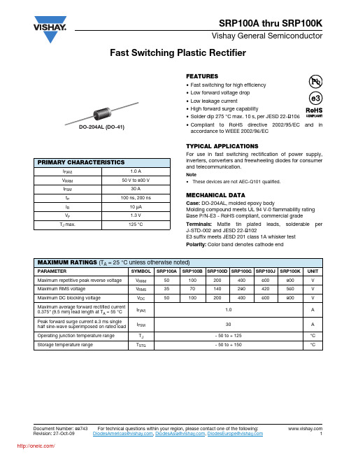
Document Number: 88743For technical questions within your region, please contact one of the following:Fast Switching Plastic RectifierSRP100A thru SRP100KVishay General SemiconductorFEATURES•Fast switching for high efficiency •Low forward voltage drop •Low leakage current•High forward surge capability•Solder dip 275 °C max. 10 s, per JESD 22-B106•Compliant to RoHS directive 2002/95/EC and in accordance to WEEE 2002/96/ECTYPICAL APPLICATIONSFor use in fast switching rectification of power supply,inverters, converters and freewheeling diodes for consumer and telecommunication.Note•These devices are not AEC-Q101 qualified.MECHANICAL DATACase: DO-204AL, molded epoxy bodyMolding compound meets UL 94 V-0 flammability rating Base P/N-E3 - RoHS compliant, commercial grade Terminals: Matte tin plated leads, solderable per J-STD-002 and JESD 22-B102E3 suffix meets JESD 201 class 1A whisker test Polarity: Color band denotes cathode endPRIMARY CHARACTERISTICSI F(AV) 1.0 A V RRM 50 V to 800 VI FSM 30 A t rr 100 ns, 200 nsI R 10 μA V F 1.3 V T J max.125 °CDO-204AL (DO-41)MAXIMUM RATINGS (T A = 25°C unless otherwise noted)PARAMETERSYMBOL SRP100ASRP100B SRP100D SRP100G SRP100J SRP100K UNIT Maximum repetitive peak reverse voltage V RRM 50100200400600800V Maximum RMS voltage V RMS 3570140280420560V Maximum DC blocking voltageV DC 50100200400600800V Maximum average forward rectified current 0.375" (9.5 mm) lead length at T A = 55 °C I F(AV) 1.0A Peak forward surge current 8.3 ms single half sine-wave superimposed on rated load I FSM 30A Operating junction temperature range T J - 50 to + 125°C Storage temperature rangeT STG- 50 to + 150°C For technical questions within your region, please contact one of the following:Document Number: 88743SRP100A thru SRP100KVishay General SemiconductorNote(1)Thermal resistance from junction to ambient at 0.375" (9.5 mm) lead length, P.C.B. mountedRATINGS AND CHARACTERISTICS CURVES(T A = 25 °C unless otherwise noted)Fig. 1 - Forward Current Derating Curves Fig. 2 - Maximum Non-repetitive Peak Forward Surge CurrentELECTRICAL CHARACTERISTICS (T A = 25°C unless otherwise noted)PARAMETER TEST CONDITIONS SYMBOL SRP100A SRP100B SRP100D SRP100G SRP100J SRP100K UNITMaximum instantaneous forward voltage 1.0 AV F1.3VMaximum DC reverse current at rated DC blocking voltage T A = 25 °C I R 10μAT A = 100 °C200Maximum reverse recovery time I F = 0.5 A, I R = 1.0 A,I rr = 0.25 A t rr 100200ns Typical junction capacitance4.0 V, 1 MHzC J12pFTHERMAL CHARACTERISTICS (T A = 25°C unless otherwise noted)PARAMETERSYMBOL SRP100A SRP100B SRP100D SRP100G SRP100J SRP100K UNIT Typical thermal resistanceR θJA (1)41°C/WORDERING INFORMATION (Example)PREFERRED P/N UNIT WEIGHT (g)PREFERRED PACKAGE CODEBASE QUANTITYDELIVERY MODESRP100J-E3/540.3354550013" diameter paper tape and reelSRP100J-E3/730.33733000Ammo pack packagingDocument Number: 88743For technical questions within your region, please contact one of the following:SRP100A thru SRP100KVishay General SemiconductorFig. 3 - Typical Instantaneous Forward Characteristics Fig. 4 - Typical Reverse Characteristics Fig. 5 - Typical Junction CapacitanceFig. 6 - Typical Transient Thermal ImpedancePACKAGE OUTLINE DIMENSIONS in inches (millimeters)Legal Disclaimer Notice VishayDisclaimerALL PRODU CT, PRODU CT SPECIFICATIONS AND DATA ARE SU BJECT TO CHANGE WITHOU T NOTICE TO IMPROVE RELIABILITY, FUNCTION OR DESIGN OR OTHERWISE.Vishay Intertechnology, Inc., its affiliates, agents, and employees, and all persons acting on its or their behalf (collectively,“Vishay”), disclaim any and all liability for any errors, inaccuracies or incompleteness contained in any datasheet or in any other disclosure relating to any product.Vishay makes no warranty, representation or guarantee regarding the suitability of the products for any particular purpose or the continuing production of any product. To the maximum extent permitted by applicable law, Vishay disclaims (i) any and all liability arising out of the application or use of any product, (ii) any and all liability, including without limitation special, consequential or incidental damages, and (iii) any and all implied warranties, including warranties of fitness for particular purpose, non-infringement and merchantability.Statements regarding the suitability of products for certain types of applications are based on Vishay’s knowledge of typical requirements that are often placed on Vishay products in generic applications. Such statements are not binding statements about the suitability of products for a particular application. It is the customer’s responsibility to validate that a particular product with the properties described in the product specification is suitable for use in a particular application. Parameters provided in datasheets and/or specifications may vary in different applications and performance may vary over time. All operating parameters, including typical parameters, must be validated for each customer application by the customer’s technical experts. Product specifications do not expand or otherwise modify Vishay’s terms and conditions of purchase, including but not limited to the warranty expressed therein.Except as expressly indicated in writing, Vishay products are not designed for use in medical, life-saving, or life-sustaining applications or for any other application in which the failure of the Vishay product could result in personal injury or death. Customers using or selling Vishay products not expressly indicated for use in such applications do so at their own risk and agree to fully indemnify and hold Vishay and its distributors harmless from and against any and all claims, liabilities, expenses and damages arising or resulting in connection with such use or sale, including attorneys fees, even if such claim alleges that Vishay or its distributor was negligent regarding the design or manufacture of the part. Please contact authorized Vishay personnel to obtain written terms and conditions regarding products designed for such applications.No license, express or implied, by estoppel or otherwise, to any intellectual property rights is granted by this document or by any conduct of Vishay. Product names and markings noted herein may be trademarks of their respective owners.Material Category PolicyVishay Intertechnology, Inc. hereb y certifies that all its products that are identified as RoHS-Compliant fulfill the definitions and restrictions defined under Directive 2011/65/EU of The European Parliament and of the Council of June 8, 2011 on the restriction of the use of certain hazardous substances in electrical and electronic equipment (EEE) - recast, unless otherwise specified as non-compliant.Please note that some Vishay documentation may still make reference to RoHS Directive 2002/95/EC. We confirm that all the products identified as being compliant to Directive 2002/95/EC conform to Directive 2011/65/EU.Revision: 12-Mar-121Document Number: 91000分销商库存信息:VISHAY-GENERAL-SEMICONDUCTORSRP100A-E3/54SRP100B-E3/54SRP100D-E3/54 SRP100G-E3/54SRP100J-E3/54SRP100K-E3/54 SRP100B-E3/73SRP100D-E3/73SRP100K-E3/73。
步进电机35412B-271规格书

交货规格书Submission of Specifications 制图日DATE2012/08/13用户NAME上海森中电器电机型号MOTOR MODEL35BYJ412B-271STEPPING MOTOR图纸编号DRAWING NO.35BJ412B-271.0.0-00WX1. 电性能及参数ELECTRIC PERFORMANCE & PROPERTIES1.1 相数4相Number of phase4 phase.1.2 驱动方式2相励磁单极驱动Drive mode2 phase excitation unipolar drive.1.3 步距角7.5°/42.5(输出轴),减速比1/42.5Step angle7.5deg/42.5(output shaft), gear reduction ratio:1/42.51.4 电压24V DC(电机端子)Voltage24V DC (motor energized voltage)1.5 线圈电阻(每相)600Ω±7%/相, 25℃时Resistance per phase600Ω±7%/phase at 25℃1.6 最大空载牵出频率200pps以上,冷态测量Max response frequencyMore than 200pps,Measurement with no coil temperature rising up1.7 最大空载牵入频率200pps以上,冷态测量Max starting frequencyMore than 200pps,Measurement with no coil temperature rising up1.8 牵入转矩24V DC(端子电压)125pps,147mN.m(1500gf.cm)以上,测矩计(353mN.m),(3600gf.cm),冷态起动Pull in torqueMore than 147mN.m(1500gf.cm) at 125pps ,24V DC(Motor energized voltage),Torquewatch 353mN.m(3600gf.cm) ,start in cold state.雷利电器 LEILI 2雷利电器 LEILI 3雷利电器 LEILI 4雷利电器 LEILI 5雷利电器 LEILI 6;Standard drive circuit:雷利电器 LEILI 7雷利电器 LEILI 8雷利电器 LEILI 9雷利电器 LEILI 10。
345EX和332EX产品系列电磁铃铛

DescriptionEdwards Catalog Series 332EX, 333EX, 340EX and 435EX Adaptabel Bells are heavy duty, UL listed audible signal-ing appliances intended for use in hazardous locations.The 332EX and 333EX series are single stroke bells suit-able for use in coded signaling applications such as tim-ing, scheduling, paging, or alarm. The 340EX and 435EX series are vibrating bells suitable for use in general sig-naling and alarm applications. The 332EX and 340EX se-ries are ac-powered and the 333EX and 435EX series are dc-powered. The bells are electromechanical devices and utilize solid state components. They are Outdoor Type 4listed. All series of the bells are listed for installation in the following hazardous locations:Installation Instructions for Catalog Series 332EX, 333EX, 340EX and 435EX Adaptabel Bells for Use in Hazardous LocationsMechanical SpecificationsDimensionsWith 6" gong ......7" (178 mm) H x 5" (127 mm) D With 8" gong 9" (229 mm) H x 5 1/8" (130 mm) D With 10" gong11" (279 mm) H x 5 1/4" (133 mm) D WeightWith 6" gong .......................5 1/4 pounds (2.4 kg)With 8" gong .............................7 pounds (3.2 kg)With 10" gong .....................8 1/4 pounds (3.8 kg)InstallationThe following items (not supplied) are required for instal-lation of the bell:•3/4" conduit to contain power supply and ground wires •One 3/4" NPT nipple•One conduit outlet box suitable for use in the hazardous location•Two fasteners up to 3/8" diameter and washers suitable for securing bell to mounting surface.•Two wire nuts.The bell can be mounted to any solid surface. Install bell as follows:1.See Figure 1. Remove cover from conduit outlet box.Feed the two wires from the applicable power sourceElectrical SpecificationsP-047550-0585 ISSUE 6 © 2005CHESHIRE, CT 203-699-3300 CUST. SERV. FAX 203-699-3365 TECH SERV. FAX 203-699-3078through conduit and into outlet box. Also, feed the bell's two wire leads through nipple and into box.Secure bell, nipple, and conduit to box.2.Remove gong from bell. Place bell against mountingsurface and mark mounting hole positions for fasteners per dimensions in Figure 2. Install fasteners with washers through mounting brackets and secure bell to surface. Replace gong in original orientation.is positive (+), black wire is negative (-). Replace cover on outlet box.4.Apply power to the bell and verify that it sounds.Maintenance and Maintenance and TT est Examine the bell annually for accumulation of dirt and clean when necessary.Test the bell annually or at the intervals required by ap-plicable regulations and codes.P-047550-0585 ISSUE 6PAGE 23.Connect power supply wires to bell wires using wirenuts. For a dc-powered bell, observe polarity--red wire。
SN74LS354中文资料

Copyright © 1988, Texas Instruments Incorporated PRODUCTION DATA information is current as of publication date.Products conform to specifications per the terms of Texas Instrumentsstandard warranty. Production processing does not necessarily includetesting of all parameters.1POST OFFICE BOX 655303 • DALLAS, TEXAS 752652POST OFFICE BOX 655303 • DALLAS, TEXAS 752653 POST OFFICE BOX 655303 • DALLAS, TEXAS 752654POST OFFICE BOX 655303 • DALLAS, TEXAS 752655 POST OFFICE BOX 655303 • DALLAS, TEXAS 752656POST OFFICE BOX 655303 • DALLAS, TEXAS 752657 POST OFFICE BOX 655303 • DALLAS, TEXAS 752658POST OFFICE BOX 655303 • DALLAS, TEXAS 752659 POST OFFICE BOX 655303 • DALLAS, TEXAS 75265元器件交易网IMPORTANT NOTICETexas Instruments and its subsidiaries (TI) reserve the right to make changes to their products or to discontinueany product or service without notice, and advise customers to obtain the latest version of relevant informationto verify, before placing orders, that information being relied on is current and complete. All products are soldsubject to the terms and conditions of sale supplied at the time of order acknowledgement, including thosepertaining to warranty, patent infringement, and limitation of liability.TI warrants performance of its semiconductor products to the specifications applicable at the time of sale inaccordance with TI’s standard warranty. Testing and other quality control techniques are utilized to the extentTI deems necessary to support this warranty. Specific testing of all parameters of each device is not necessarilyperformed, except those mandated by government requirements.CERTAIN APPLICATIONS USING SEMICONDUCTOR PRODUCTS MAY INVOLVE POTENTIAL RISKS OFDEATH, PERSONAL INJURY, OR SEVERE PROPERTY OR ENVIRONMENTAL DAMAGE (“CRITICALAPPLICATIONS”). TI SEMICONDUCTOR PRODUCTS ARE NOT DESIGNED, AUTHORIZED, ORWARRANTED TO BE SUITABLE FOR USE IN LIFE-SUPPORT DEVICES OR SYSTEMS OR OTHERCRITICAL APPLICATIONS. INCLUSION OF TI PRODUCTS IN SUCH APPLICATIONS IS UNDERSTOOD TOBE FULLY AT THE CUSTOMER’S RISK.In order to minimize risks associated with the customer’s applications, adequate design and operatingsafeguards must be provided by the customer to minimize inherent or procedural hazards.TI assumes no liability for applications assistance or customer product design. TI does not warrant or representthat any license, either express or implied, is granted under any patent right, copyright, mask work right, or otherintellectual property right of TI covering or relating to any combination, machine, or process in which suchsemiconductor products or services might be or are used. TI’s publication of information regarding any thirdparty’s products or services does not constitute TI’s approval, warranty or endorsement thereof.Copyright © 1999, Texas Instruments Incorporated。
奥伦德光耦产品对比表V3.1

LTV-824
LTV-844 LTV-214 LTV-354T
LTV-815 LTV-825 LTV-845 LTV-215
PS2702-1
LTV-355T
EL EL817
EL827 EL847 EL3H7 EL357
EL816 EL10XX
4N3X H11AX 4N2X H11AX EL814
消除地面回路,LSTTL to TTL,LSTTL or 5 volt CMOS 线接收器,数据 传输,开关电源,脉冲变压器更换,计算机外设接口,地面高速
逻辑隔离
TYPE
ORIENT AVAGO FAIRCHILD TOSHIBA
OR817 HCPL-817
H11A817 FOD817
TLP521-1
股票代码:832016
深圳奥伦德依托 20 多年积累的红外芯片技术,深耕光电耦合器十余载,是大陆首家通过 VDE、UL、CQC 认证并 量产化的企业。我司光耦产品伴随几百家客户 10 多年来一起成长,积累销售光耦近百亿只,产品走入千家万户。 作为一种安全器件,为广大用户提供了保证。是国内公认的历史最久、产能最大、型号最全的光耦芯片及封装研发 和生产基地。
SHARP
RENESA
VISHAY
LITEON
EL
COSMO
OR301X OR302X OR304X OR305X
OR306X
OR308X
Thyristor
MOC302X
MOC304X
MOC305X
MOC306X
OR155E
ORM501
ORM600
ORM601
ORM611
High-speed
LTV354T-A中文资料
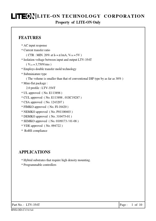
FEATURES* AC input response* Current transfer ratio( CTR : MIN. 20% at I F =±1mA, V CE =5V )* Isolation voltage between input and output LTV-354T( V iso =3,750Vrms )* Employs double transfer mold technology* Subminiature type( The volume is smaller than that of conventional DIP type by as far as 30% ) * Mini-flat package :2.0 profile : LTV-354T* UL approved ( No. E113898 )* CUL approved ( No. E113898 , 01SC19287 )* CSA approved ( No. 1243207 )* FIMKO approved ( No. FI-16420 )* NEMKO approved ( No. P0******* )* DEMKO approved ( No. 310475-01 )* SEMKO approved ( No. 0109173 / 01-08 )* VDE approved ( No. 094722 )* RoHS complianceAPPLICATIONS* Hybrid substrates that require high density mounting.* Programmable controllersOUTLINE DIMENSIONSLTV-354T :*1. 2-digit date code.*2. Factory identification mark shall be marked (Z : Taiwan, Y : Thailand, X : China).*3. Rank shall be or shall not be marked.ABSOLUTE MAXIMUM RATING( Ta = 25°C ) PARAMETER SYMBOL RATING UNITForward Current I F±50 mA INPUTPower Dissipation P 70 mWCollector - Emitter Voltage V CEO35 VEmitter - Collector Voltage V ECO 6 V OUTPUTCollector Current I C50 mACollector Power Dissipation P C150 mW Total Power Dissipation P tot170 mW*1 Isolation Voltage V iso3,750 Vrms Operating Temperature T opr-55 ~ +100 °CStorage Temperature T stg-55 ~ +150 °C*2 Soldering Temperature T sol260 °C*1. AC For 1 Minute, R.H. = 40 ~ 60%Isolation voltage shall be measured using the following method.(1) Short between anode and cathode on the primary side and between collector andemitter on the secondary side.(2) The isolation voltage tester with zero-cross circuit shall be used.(3) The waveform of applied voltage shall be a sine wave.*2. For 10 SecondsRANK TABLE OF CURRENT TRANSFER RATIO CTRMODEL NO. RANK MARK CTR ( % )A 50 ~ 150LTV-354TA or No mark 20 ~ 400CONDITIONS I F = ±1 mA V CE = 5 V Ta = 25 °CTEMPERATURE PROFILE OF SOLDERING REFLOW(1)One time soldering reflow is recommended within the condition of temperature and timeprofile shown below.。
LTV-354T中文资料

%
&# 0
##
4
) *+!,
4%
8
元器件交易网
&,- /- % 4- % 0 4- % & , , & ,
± .
± ±
±
±
" #±
4
) *+!,
4%
+ 8
元器件交易网
元器件交易网
! " # $ # % & ' ( ) *+!, +-!
# ) *+!, 6)
$ ( .+787" 6)
$ ( .+787287-" 2
$ ( ,+-" 9:;
$ ( 9*<," .:;
5 5 5 . 5
5 5 5 5 5
5 5 5
#
# , ! ' , , ' < , Ω ! µ µ $ &6± ' ,6 16
789 ,6 ,1&6 &6
' &6 &6
µ' &6 &6±
' ,6, &6± ' &6
' $ , 2. <; 8 ,6 16
PC354中文资料

of
元器件交易网
SHARP CORPORATION
ED-94(
1. Application This specification applies Model No. PC354. to the outline and characteristics of p
2. Outline Refer to the attached drawing No. CY6488KO2.
元器件交易网
SHARP CORPORATION
2. Outline i
0
.
c @
3.6kO. 3
;
2.54kO.25
i / Date code
Pin Nos. and internal connection diagram
Sharp mark “S”,
\,
1
Model No. \ Primary side mark \
元器件交易网
PREPARED BY: DATE:
SHA
APPROVED
BY: DATE: ELECTRONIC COMPO GROUP SHARP CORPORATION
I SPEC.
No.
ED-9466 October
1B 29. 1999
SPECIFICATION
DEVICE SPECIFICATION FOR Business
6.5 This product 6.6 This product This product This product 6.7 ODS materials
is AC input
type. against irradiation. input and output. diode.
en354标准

en354标准
EN 354是欧洲标准,主要针对个人坠落保护系统中的挂绳做出规范。
具体
来说,它是灵活、独立的连接元件或连接系统组件,如用于约束系统、工作定位系统、绳索进入系统、防坠落系统和救援系统。
挂绳的端点至少有两个,最大长度为2000毫米。
挂绳的材料可以是织带、绳索、金属、钢丝绳或链条。
端子可以缝制、打结或带有金属环。
EN 354标准还规定了挂绳在不同环境条件下的测试要求,包括一般空调、
适应湿冷和极端寒冷环境等。
在动态强度测试中,挂绳通过让测试质量自由下落来测试,带长度调节装置的挂绳滑动不得超过50毫米。
此外,制造商在产品上需要提供一些强制性信息,包括制造商/商品名称和
制造年份/月份、充电编号和类型/型号名称、EN 354 + 发行年份、参考用
户手册、挂绳长度以及CE认证标志等。
以上内容仅供参考,如需更多信息,建议查阅EN 354标准原文或咨询专业人士。
el354n光耦参数

el354n光耦参数
(原创实用版)
目录
1.光耦的概述
2.el354n 光耦的主要参数
3.el354n 光耦参数的应用
4.el354n 光耦参数的优势
正文
光耦,全称光电耦合器,是一种电子元件,它是通过光电效应将输入端的电信号转换为输出端的光信号,进而实现电气隔离的功能。
在各种光耦中,el354n 光耦以其优良的性能和稳定的可靠性,被广泛应用在各种电子设备中。
el354n 光耦的主要参数包括:CTR(电流传输比),ITR(输入光强与光耦电流之比),CTRmin(最小电流传输比)和 CTRmax(最大电流传输比)等。
其中,CTR 是衡量光耦性能的重要参数,它直接影响到光耦的传输效率。
ITR 则决定了光耦的灵敏度,ITR 越大,光耦对输入光强的要求就越低,从而提高其应用的灵活性。
而 CTRmin 和 CTRmax 则规定了光耦的工作范围,超过这个范围,光耦的传输性能就会下降。
el354n 光耦参数的应用主要体现在其电气隔离功能上。
由于光耦的输入端和输出端是通过光信号进行传输,因此,即使输入端有很强的电流,输出端也不会受到影响,从而实现了电气隔离。
这种功能在工业控制系统,尤其是高电压、高电流的系统中,有着重要的应用价值。
el354n 光耦参数的优势主要体现在其稳定性和可靠性上。
由于光耦的传输过程不涉及电流的直接传输,因此,其抗干扰能力强,传输稳定性高。
el354n光耦参数
el354n光耦参数
摘要:
1.光耦概述
2.el354n光耦参数介绍
3.el354n光耦的应用领域
正文:
光耦是一种光电元件,通过光电效应将光信号转换为电信号。
在电路设计中,光耦广泛应用于隔离、放大、开关等功能。
今天我们将重点介绍一款
el354n光耦的参数及其应用领域。
1.光耦概述
光耦,全称为光电耦合器,是一种将光信号与电信号相互转换的器件。
光耦具有高速、低失真、低噪声、高隔离度等优点,使其在电子、电气、通信等领域得到广泛应用。
2.el354n光耦参数介绍
el354n光耦是德州仪器(TI)公司生产的一款光耦产品,其主要参数如下:
- 电流传输比(CTR):30% to 60%
- 输入输出隔离电压:5000 Vrms
- 工作温度范围:-40°C to 125°C
- 封装:SO-8
此外,el354n光耦还具有较低的正向电压、较快的上升和下降时间等特
性。
这些参数使得el354n光耦在各种应用场景中表现出色。
3.el354n光耦的应用领域
el354n光耦广泛应用于以下领域:
- 电源管理:用于隔离、转换和控制电源系统中的信号,提高系统稳定性和可靠性。
- 通信系统:在光通信网络中,光耦用于隔离和放大光信号,保证通信质量。
- 工业控制:在工业自动化领域,光耦常用于实现信号隔离、安全控制等功能。
- 消费电子:在音响、电视、摄像机等消费电子产品中,光耦用于信号放大、切换等。
总之,el354n光耦凭借其优良的性能参数,在各个领域都取得了广泛的应用。
el354n光耦参数

el354n光耦参数EL354N光耦是一种广泛应用于电子设备中的光电器件,它能够实现电气信号和光信号之间的传输和隔离。
本文将围绕EL354N光耦的参数展开讨论,包括其电气特性、应用领域等方面。
EL354N光耦的输入和输出电气特性是我们了解其性能的重要指标。
EL354N光耦的输入电流为 5 mA,而输出电流为20 mA。
此外,EL354N光耦的额定输入电压为 1.5 V,额定输出电压为 5 V。
这些参数表明EL354N光耦具有较高的输入和输出灵敏度,适用于各种电子设备。
EL354N光耦还具有较高的切换速度和隔离电阻。
其切换速度为 1 μs,隔离电阻为10^11Ω。
这意味着EL354N光耦能够在短时间内完成输入和输出信号的切换,并且能够有效地隔离输入和输出信号,保证系统的安全性和稳定性。
EL354N光耦的工作温度范围为-40℃至85℃,工作电压范围为 3 V 至20 V。
这些参数表明EL354N光耦能够在较宽的温度和电压范围内正常工作,适用于各种环境条件下的应用。
在实际应用中,EL354N光耦具有广泛的应用领域。
首先,它可以用于电源开关控制。
通过EL354N光耦的输入和输出信号隔离,可以实现对电源开关的控制,提高电路的稳定性和安全性。
EL354N光耦也可以用于电动机控制。
通过EL354N光耦将控制信号与电动机隔离,可以有效地保护控制电路和电动机,提高系统的可靠性和稳定性。
EL354N光耦还可以用于光电耦合器和光电继电器等应用。
通过光电耦合器可以实现光信号的传输和隔离,而通过光电继电器可以实现对高压高电流的控制,保护低压低电流的控制电路。
需要注意的是,EL354N光耦在使用时需要遵循一定的操作规范。
首先,应正确连接光耦输入和输出端子,避免接反或短路等错误连接。
其次,应注意光耦的工作温度和电压范围,避免超出其额定范围,以免损坏光耦或影响其正常工作。
EL354N光耦是一种具有较高输入和输出灵敏度、切换速度和隔离电阻的光电器件。
el354n光耦参数
el354n光耦参数EL354N光耦参数详解光耦是一种常见的光电器件,它能够将输入信号转换为光信号,并通过光电转换将光信号转换为输出电信号。
EL354N是一种常用的光耦,具有以下参数:1. 工作电压:EL354N的工作电压范围为3V至20V。
这意味着在使用EL354N时,输入和输出电路的电压应在这个范围内,以确保正常的工作。
2. 输入电流:EL354N的输入电流为5mA。
这表示在将输入信号接入EL354N时,输入端的电流应限制在5mA以内,以避免损坏器件。
3. 输出电流:EL354N的输出电流为50mA。
这意味着当光耦接收到光信号后,输出端可以提供最大50mA的电流输出,用于驱动外部电路。
4. 隔离电压:EL354N的隔离电压为2500Vrms。
这意味着在EL354N的输入和输出之间存在一个隔离层,可以有效地隔离输入和输出电路,以提高安全性。
5. 工作温度范围:EL354N的工作温度范围为-40℃至85℃。
这表示EL354N可以在较宽的温度范围内正常工作,适用于各种环境条件。
6. 响应时间:EL354N的响应时间为3μs。
这意味着当输入信号发生变化时,EL354N能够在3微秒内完成光电转换并输出相应的电信号。
7. 封装类型:EL354N采用了DIP-8封装。
这种封装形式方便了EL354N的安装和连接,并且具有良好的散热性能。
8. 应用领域:EL354N广泛应用于电力控制、工业自动化、通信设备等领域。
其可靠性高、响应速度快的特点使其成为许多电子设备中的重要组成部分。
总结起来,EL354N光耦具有工作电压范围广、输入输出电流适中、隔离电压高、工作温度范围宽、响应时间短等特点,适用于各种应用场景。
作为一种常用的光耦器件,EL354N在电子领域中发挥着重要的作用,为各种电路的设计和实现提供了可靠的光电转换解决方案。
el354n光耦参数
EL354N光耦参数1. 概述EL354N是一款常用的光耦器件,用于电子设备中的隔离和信号传输。
本文将详细介绍EL354N光耦的参数,包括电气参数、光学参数和封装参数等。
2. 电气参数EL354N的电气参数是评估其性能的关键指标。
以下是常见的电气参数:•输入电流(IF):光耦的输入电流范围,通常以毫安(mA)为单位。
•输出电流(IO):光耦的输出电流范围,也以毫安为单位。
•隔离电压(VISO):光耦器件的输入和输出之间的最大电压。
•工作温度范围(TJ):光耦器件能够正常工作的温度范围。
•响应时间(tR,tF):光耦器件的输出响应时间,通常以纳秒为单位。
3. 光学参数EL354N的光学参数描述了光耦器件的发光和接收特性。
以下是常见的光学参数:•发光器件:EL354N包含一个发光二极管(LED),其发光波长通常在红外范围。
•接收器件:EL354N包含一个光敏二极管(Phototransistor),用于接收光信号。
•光耦比(CTR):光耦比是光耦器件的输出电流与输入电流之间的比值,通常以百分比表示。
•光电流(IF=0):当输入电流为零时,光耦器件的输出电流。
4. 封装参数EL354N的封装参数描述了器件的物理尺寸和引脚排布。
以下是常见的封装参数:•封装类型:EL354N通常采用双列直插封装(DIP)或表面贴装封装(SMD)。
•引脚数目:EL354N的引脚数目,通常为4或6个。
•引脚排布:EL354N的引脚排布图,显示每个引脚的功能和连接方式。
5. 应用领域EL354N广泛应用于各种电子设备中,特别是需要隔离和信号传输的场景。
以下是一些常见的应用领域:•电源隔离:EL354N可以用于隔离电源和控制电路,提供安全和稳定的电源传输。
•信号隔离:EL354N可以用于隔离模拟或数字信号,防止干扰和噪音传播。
•数据传输:EL354N可以用于光纤通信或光电耦合接口,实现高速数据传输。
•开关控制:EL354N可以用于控制开关电路,实现远程操作和控制。
el354n光耦参数

el354n光耦参数EL354N光耦参数EL354N是一款常用的光耦,具有多种参数和特性,适用于各种电子设备和电路应用。
本文将详细介绍EL354N光耦的各项参数,并解释其对于电路性能的影响。
1. 输入电流传输比(CTR):输入电流传输比是光耦的一个重要参数,表示光耦输出端光敏电流与输入端驱动电流之间的比值。
EL354N的CTR通常在50%至600%之间。
CTR越高,表示光耦的输出电流更大,驱动能力更强。
2. 隔离电压(Viso):隔离电压是指光耦输入端和输出端之间的最大工作电压。
EL354N的隔离电压一般为2500Vrms。
较高的隔离电压能够有效防止输入信号对输出信号的干扰,提高电路的稳定性和安全性。
3. 切换时间(tON、tOFF):切换时间是指光耦输出端从关断状态到导通状态(tON)和从导通状态到关断状态(tOFF)所需的时间。
EL354N的切换时间通常在0.3μs至10μs之间。
较短的切换时间能够提高光耦的响应速度,适用于高频率的电路应用。
4. 灵敏度:灵敏度是指光耦输入端所需的最小驱动电流。
EL354N的灵敏度一般为5mA。
较低的灵敏度表示光耦可以在较小的输入电流下正常工作,降低了功耗和驱动电路的复杂度。
5. 工作温度范围:EL354N的工作温度范围通常在-40°C至+85°C之间。
在这个温度范围内,光耦可以正常工作并保持稳定的性能。
超出工作温度范围可能导致光耦的性能下降甚至损坏。
6. 安装方式:EL354N的安装方式一般有SMD和DIP两种。
SMD(表面贴装)适用于高密度集成电路的应用,而DIP(双列直插)适用于一般电子设备的应用。
根据具体的应用需求选择合适的安装方式。
7. 应用领域:EL354N广泛应用于各种电子设备和电路中,包括电力控制、自动化设备、通信设备、工业控制等领域。
通过光耦的隔离和传输功能,可以实现输入和输出信号的电气隔离和信号传输,提高电路的稳定性和安全性。
- 1、下载文档前请自行甄别文档内容的完整性,平台不提供额外的编辑、内容补充、找答案等附加服务。
- 2、"仅部分预览"的文档,不可在线预览部分如存在完整性等问题,可反馈申请退款(可完整预览的文档不适用该条件!)。
- 3、如文档侵犯您的权益,请联系客服反馈,我们会尽快为您处理(人工客服工作时间:9:00-18:30)。
4 PIN SOP PHOTOTRANSISTORAC INPUT PHOTOCOUPLEREL354 Series Features:• AC input response • Current transfer ratio(CTR: Min. 20% at I F =±1mA ,V CE =5V) • High isolation voltage between input and output (Viso=3750 V rms ) • Compact small outline package • Pb free and RoHS compliant. • UL approved (No. E214129) •VDE approved (No. 132249) • SEMKO approved (No. 716108) • NEMKO approved (No. P0*******) • DEMKO approved (No. 313924) Schematic• FIMKO approved (No. FI 22807) • CSA approved (No. 1408633)DescriptionThe EL354 series of devices each consist of two infrared emitting diode, connected in inverse parallel, optically coupled to a phototransistor detector.They are packaged in a 4-pin small outline package. Pin Configuration 1. Anode / Cathode 2. Cathode / Anode 3. Emitter 4. CollectorApplications• AC line monitor• Programmable controllers • Telephone line interface• Unknown polarity DC sensor4 PIN SOP PHOTOTRANSISTORAC INPUT PHOTOCOUPLER EL354 SeriesAbsolute Maximum Ratings (T a=25°C)Parameter SymbolRatingUnit Forward current I F±50 mAPeak forward current (t = 10µs) I FM 1 AInputPower dissipationNo derating required up to T a = 100°C P D70mW150 mWPower dissipationDerating factor (above T a = 80°C) P C3.7 mW/℃Collector-Emitter voltage V CEO80 VOutputEmitter-Collector voltage V ECO 6 VTotal power dissipation P tot200 mW Isolation voltage *1V iso3750 Vrms Operating temperature T opr-55~+100 °C Storage temperature T stg-55~+125 °C Soldering temperature *2T sol260 °C Notes*1AC for 1 minute, R.H.= 40 ~ 60% R.H. In this test, pins 1 & 2 are shorted together, and pins 3 & 4are shorted together.*2For 10 seconds.4 PIN SOP PHOTOTRANSISTORAC INPUT PHOTOCOUPLEREL354 Series Electrical Characteristics (T a =25°C unless specified otherwise)InputParameter Symbol Min. Typ.* Max. Unit ConditionForward voltage V F- 1.2 1.4 V I F = ± 20mA Reverse current I R- - 10 µA V R = 4V Input capacitanceC in-50250pFV = 0, f = 1KHzOutputParameter Symbol Min. Typ.* Max. Unit ConditionCollector-Emitter darkcurrentI CEO - - 100 nA V CE = 20V, I F =0mA Collector-Emitter breakdown voltage BV CEO 80 - - VI c =0.1mAEmitter-Collector breakdown voltage BV ECO6 - - V I E =0.01mATransfer Characteristics (T a =25°C unless specified otherwise)Parameter Symbol Min. Typ.* Max. Unit ConditionEL354 20 - 300Current TransferratioEL354A CTR 50 - 150% I F = ±1mA ,V CE = 5VCollector-emitter saturationvoltageV CE(sat) - 0.1 0.2 V I F = ±20mA ,I c = 1mA Isolation resistance R IO 5×10101011 - ΩV IO = 500Vdc, 40~60%R.HCut-off frequency f c - 80 - kHzV CE =5V, I C =2 mA,R L =100Ω, -3dB Floating capacitance C IO - 0.6 1.0 pF V IO = 0, f = 1MHz Rise time T r - 6 18 µs Fall timeT f- 8 18 µsV CE =2V, I C =2mA,R L =100Ω* Typical values at T a = 25°CPIN SOP4AC INPUT PHOTOCOUPLERPHOTOTRANSISTOREL354 SeriesTypical Performance CurvesPIN SOP4 AC INPUT PHOTOCOUPLERPHOTOTRANSISTOR EL354 SeriesFigure 10. Switching Time Test Circuit & WaveformsOutput4 PIN SOP PHOTOTRANSISTORAC INPUT PHOTOCOUPLER EL354 SeriesOrder InformationPart NumberEL354(X)(Y)-VNoteX = CTR Rank option (A or none)Y = Tape and reel option (TA, TB, or none).V = VDE safety optionquantity Option Description PackingNone Standard SMD option 100 units per tube-V Standard SMD option + VDE 100 units per tube(TA) TA Tape & reel option 3000 units per reel(TB) TB Tape & reel option 3000 units per reel(TA)-V TA Tape & reel option + VDE 3000 units per reel(TB)-V TB Tape & reel option + VDE 3000 units per reel4 PIN SOP PHOTOTRANSISTORAC INPUT PHOTOCOUPLER EL354 SeriesPackage Drawings(Dimensions in mm)Package Drawing(Dimensions in mm)Recommended pad layout for surface mount leadform4 PIN SOP PHOTOTRANSISTORAC INPUT PHOTOCOUPLER EL354 Series MarkingDeviceEL354RYWWVNotesEL denotes Everlight354 denotes Device NumberR denotes CTR Rank (A or none)Y denotes 1 digit Year codeWW denotes 2 digit Week codeV denotes VDE approved (optional)4 PIN SOP PHOTOTRANSISTORAC INPUT PHOTOCOUPLEREL354 Series Tape & Reel Packing SpecificationsDirection of feed from reelDirection of feed from reelTape dimensionsDimension No. A B Do D1 E FDimension (mm)4.4 ± 0.17.4 ± 0.11.5 + 0.1/-01.5 ± 0.11.7 5± 0.17.5 ± 0.1Dimension No. Po P1 P2 t W K Dimension (mm)4.0 ± 0.15 8.0 ± 0.1 2.0 ± 0.1 0.25 ± 0.0316.0 ± 0.2 2.4 ± 0.14 PIN SOP PHOTOTRANSISTORAC INPUT PHOTOCOUPLER EL354 Series Solder Reflow Temperature ProfileTIME (S)4 PIN SOP PHOTOTRANSISTOR AC INPUT PHOTOCOUPLEREverlight Electronics Co., Ltd. 11 Document No :DPC-ELST-354 Rev.1 April 1, 2008 EL354 Series DISCLAIMER1. The specifications in this datasheet may be changed without notice. EVERLIGHT reserves the authorityon material change for above specification.2. When using this product, please observe the absolute maximum ratings and the instructions for use asoutlined in this datasheet. EVERLIGHT assumes no responsibility for any damage resulting from use of the product which does not comply with the absolute maximum ratings and the instructions included in this datasheet.3. These specification sheets include materials protected under copyright of EVERLIGHT. Reproduction in any form is prohibited without the specific consent of EVERLIGHT.元器件交易网。
