进口瑞士变频器说明书5_Technical datas
【变频器说明书】欧瑞ZS500说明书

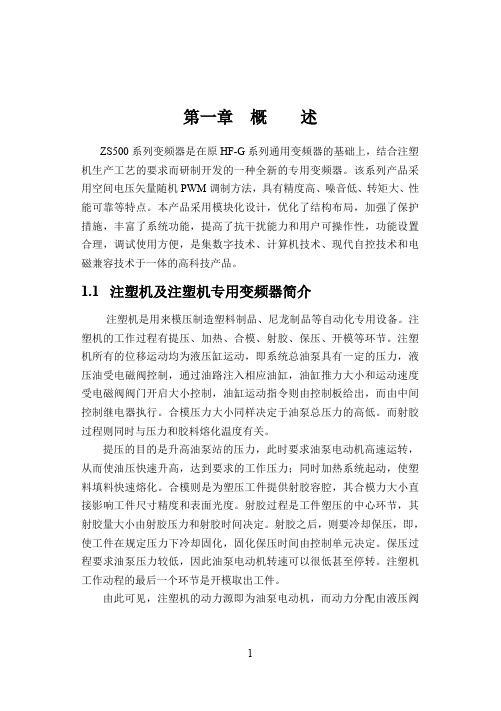
第一章概述ZS500系列变频器是在原HF-G系列通用变频器的基础上,结合注塑机生产工艺的要求而研制开发的一种全新的专用变频器。
该系列产品采用空间电压矢量随机PWM调制方法,具有精度高、噪音低、转矩大、性能可靠等特点。
本产品采用模块化设计,优化了结构布局,加强了保护措施,丰富了系统功能,提高了抗干扰能力和用户可操作性,功能设置合理,调试使用方便,是集数字技术、计算机技术、现代自控技术和电磁兼容技术于一体的高科技产品。
1.1注塑机及注塑机专用变频器简介注塑机是用来模压制造塑料制品、尼龙制品等自动化专用设备。
注塑机的工作过程有提压、加热、合模、射胶、保压、开模等环节。
注塑机所有的位移运动均为液压缸运动,即系统总油泵具有一定的压力,液压油受电磁阀控制,通过油路注入相应油缸,油缸推力大小和运动速度受电磁阀阀门开启大小控制,油缸运动指令则由控制板给出,而由中间控制继电器执行。
合模压力大小同样决定于油泵总压力的高低。
而射胶过程则同时与压力和胶料熔化温度有关。
提压的目的是升高油泵站的压力,此时要求油泵电动机高速运转,从而使油压快速升高,达到要求的工作压力;同时加热系统起动,使塑料填料快速熔化。
合模则是为塑压工件提供射胶容腔,其合模力大小直接影响工件尺寸精度和表面光度。
射胶过程是工件塑压的中心环节,其射胶量大小由射胶压力和射胶时间决定。
射胶之后,则要冷却保压,即,使工件在规定压力下冷却固化,固化保压时间由控制单元决定。
保压过程要求油泵压力较低,因此油泵电动机转速可以很低甚至停转。
注塑机工作动程的最后一个环节是开模取出工件。
由此可见,注塑机的动力源即为油泵电动机,而动力分配由液压阀控制。
工频拖动时,油泵电机50HZ恒速运转,压力调节和保持则由泻压阀进行,系统效率较低,能耗较大。
事实上,保压过程只需要较低的压力以维持一定的合模力即可。
因此,此时电机可以停止运行。
ZS500系列注塑机专用变频器内置模拟量输入隔离电路、10V或24V 备用电源,增加了模拟量输入通道的指令切换、输入输出模拟量调节范围的设置(及量程补偿)、电流电压显示、全程失速调节、积分式过载保护、转差补偿、直流制动、定时操作等功能,使操作使用更为方便。
欧科变频器说明书文档

欧科变频器说明书文档(总8
页)
-CAL-FENGHAI.-(YICAI)-Company One1
-CAL-本页仅作为文档封面,使用请直接删除
欧科变频器的P01基本功能组,主要有以下功能:控制模式;运行指令信道;编码器及端子递增+/递减-设定;频率指令选择;转矩设定方式选择;键盘设定转矩;上限频率设定源选择;最大输出频率;运行频率上限;运行频率下限;键盘设定频率;加速时间1;减速时间1;运行方向选择;载波频率设定;功能参数恢复;AVR功能选择
P01组基本功能组
启动运行方式;启动开始频率;启动频率保持时间;启动前制动电流;启动前制动时间;停机方式选择;停机制动开始频率;停机制动等待时间;停机直流制动电流;停机直流制动时间;正反转死区时间;上电端子运行保护选择;预留
欧科变频器P02启停控制组主要具有以下功能:启动运行方式;启动开始频率;启动频率保持时间;启动前制动电流;启动前制动时间;停机方式选择;停机制动开始频率;停机制动等待时间;停机直流制动电流;停机直流制动时间;正反转死区时间;上电端子运行保护选择;预留
P02组启停控制组。
ig5说明书

¨
本安装手册中大多数图表在表示时,变频器没有安装断路器,外壳或部分开路。变频器决不会 像这样运行。当运行变频器时,总是安装外壳与断路器的,并遵守安装手册中的规定。
目
录
用户使用指南 (iG5 规范) ...................................................... 3 第一章
5.6
ASC11 代码清单 ............................................................. 82
感谢您选购 LS 变频调速器!
安全注意事项
n n
始终遵守安全注意事项可以防止意外事故及潜在危险的发生。 在本使用手册中,安全等级分类如下: 危险 注意
不正确的操作可能导致严重的人身伤害或死亡。
不正确的操作可能导致轻微的人身伤害或物体硬件的损坏。
在本说明书中,全篇使用以下两个图标以使你能明白安全注意事项。 在某些确定的条件下可以识别导致人身伤害的危险。 由于危险电压可能已出现,所以应有意识地特别注意。 在某些确定的条件下可以识别潜在的危险。 仔细阅读相关信息并遵守相关指令。
第五章 内置通讯功能 ......................................................... 67
5.1 5.2 5.3 5.4 5.5 5.6 5.7 5.8 介绍 ....................................................................... 67 详述 ....................................................................... 67 设置 ....................................................................... 68 运行 ....................................................................... 69 MODBUS 通讯协议 ........................................................... 69 LS 专用通讯协议 ............................................................. 69 参数编码目录 ............................................................... 74 故障维修 ................................................................... 80
SANKEN SAMCO-VM05系列变频器中文操作说明书

SANKEN SAMCO-VM05系列变频器中文操作说明书SANKEN SAMCO-VM05系列变频器中文操作说明书 2000年2月版士林电机自动化事业处营业三课由衷地感谢您购买日本サンケン(SANKEN) 牌 32 位元 RISC架构、具有 V/F控制模式与Sensorless(或称速度推算式、无速度传感式)向量控制模式可供选择的SAMCO-vm05系列双重额定、高性能、静音型泛用变频器。
装设这部变频器之后,您的三相感应马达立刻具有无段变速的机能。
由于32位RISC演算速度快、程序容量大,因此具备多机能、操作容易的特点。
为了让您充分地享用这部变频器的特性与机能,务必详阅这本操作说明书。
当您使用中发现任何疑难时,请立刻就近向士林电机的FA产品经销商洽询,或拨电话(03)597-0921转231~233通知士林电机自动化营业部营业三课,我们的专业人员随时都等待着为您做热诚地服务。
在此我们再度深切地期望您永远爱顾的优良产品。
台湾总代理:士林电机厂股份有限公司安全通告●为了要预先防范您以及第三者因采用本产品而导致对人体危害或财产损失,因此在这本操作说明书上明确地登载着各种警告与禁制事项,请务必遵守。
使用本产品以前请务必详阅这本操作说明书,并请依照正确的方式使用。
●这本操作说明书务必放置在设备、机台的旁边或是便于取阅的地方,以便使用者查阅。
●对于安全注意事项等级,在说明书内分为「危险」、「注意」两级。
操作人员如果不理会而误操作时,可能会对人体造成伤亡危险件的事项。
操作人员如果不理会而误操作时,可能会造成人体伤害或对注意财物造成损失的事项。
※还有,即使是「注意」所记载内容都是属于必需遵守的重要事项,不予理会时亦可能会引发不可臆测的后果。
标志解说危险标志标志之后所叙述的是具体的危险内容。
注意标志标志之后所叙述的是具体的注意内容。
禁止(不可为)标志标志之后所叙述的是具体的禁止内容。
强制(不可不为)标志标志之后所叙述的是具体的强制内容。
变频器操作说明讲解

数字操作器的操作部分
键名功能LOCA源自/RRMO 根据参数o2-01的设定可以设
TE
定该键的有效/无效。
(运行操作选择) 有效时,按此键切换用数字
操作器运行还是用控制回路
端子控制运行。
MENU (菜单)
按此键在五种模式之间进行 切换。
ESC (退回)
按此键,返回到前一个状态。
JOG (点动)
在操作器运行场合的点动运行 键。
FWD/REV 在操作器运行场合,切换旋转 (正转/反转) 方向。
SHIFT/RESET 参数设置时的数位选择键。
模式的切换
按MENU键选择操作模式,例如进入 到QUICK程序模式时,对应的LED指 示灯开始闪烁,继续按MENU键则进 入下一个ADV程序模式,如此循环。 如果确定要进入某一种模式,则在该 模式的指示灯闪烁时按一次↙键,则 指示灯保持点亮状态而不再闪烁。此 时可以进一步修改具体的参数。
参数设定操作实例:
要将参数c1-02(减速时间)从10秒变更 到5秒的设定顺序。 1:接通电源,数字操作器显示“F
0.0”。 2:按下MENU键,选择驱动模式,
此时DRIVE的指示灯闪烁。 3:按下MENU键,选择QUICK程
序模式,此时QUICK的指示灯闪 烁。
4:按下MENU键,选择ADVANCED 程序模式。此时ADV的指示灯闪烁, 数字操作器显示“A1-00”。
STOP (停止键)
用操作器运行时,按此键变 频器停止运行。
用控制回路端子运行的场合, 根据参数o2-02的设定可以设 定该参数有效/无效。
欧瑞F2000-M变频器说明书(新)

F2000-M0007S2B中频专用系列变频器(0.4-45KW)一、产品简介1)产品概述F2000-M中频专用变频器,是在F1000-M基础上研制的全新一代中频专用变频器,采用高速DSP 电机控制专用芯片,应用优化的空间电压矢量控制方法,最高输出频率可达到1300Hz。
采用转矩优化算法、模块化设计,可以满足对转矩要求较高的用户需求,丰富了系统功能,提高了抗干扰能力和可操作性。
能够满足多种场合的需求,是一款高品质、多功能、低噪音、大转矩专用系列变频器。
2)产品特性●采用全新的操作方式,应用灵活,功能强大●可实现Modbus上位机控制●直线式转矩补偿和自定义转矩补偿,能适应所有高频负载●具有点动调速、多段速调速、模拟量调速、脉冲给定调速、编码调速、上位机调速、组合调速等多种调速方式●具有方便灵活的两线式、三线式控制●完善的变频器、电机保护、预报警功能●具有两路独立的模拟量输出通道●具有直流制动功能3)技术参数4)外形结构示意图塑壳外形金属外形二、操作面板1)、面板操作2)、参数设置变频器内有众多的功能参数,用户更改这些参数可以实现不同的控制运行方式,需要说明的是,在断过电或发生过保护后,如果要设置参数,必须先输入用户密码,即按下表方式调出F100,输入正确的密码。
出厂时,用户密码设为8。
参数设置步骤或或3)功能码区内与区间的切换本产品对用户开放参数(功能码)共有300多个,分为十个区,如下表功能码分区由于功能码多,参数设置耗费时间,为此专门设计了“功能码区内和功能码区之间切换”的功能,使参数设置方便易行。
按“方式”键,是键盘控制器上显示功能码,此时若按“▲”或“▼”键,则功能码在区内循环的递增或递减:如果再按一次“停/复”键,则操作“▲”或“▼”键时,功能码区之间循环变化。
4)面板显示内容面板显示项目内容及说明三、安装接线1)接线功率回路接线如下:控制回路接线如下:A)单相0.4kw-1.5kw和三相0.75kw-30kw变频器控制端子如下图所示:B)单相2.2kw变频器控制端子如下图所示:A+/B-两位端子只会在客户特殊订货要求带MODBUS通讯时才有效。
F5MS说明书

为了监控某个动作的正确执行,有些参数会发送一个状态信号。例如,在复制了一个 集之后,显示屏上显示“PASS”则表示动作执行无误,这些状态信号必须用 ENTER 键进行确认。
-
- ud.1
rpm
- ru.9
rpm
- ru.1
-
- ru.0
A
- ru.15
A
- ru.16
Nm
- ru.12
V
- ru.18
V
- ru.19
V
- ru.20
-
- cs.0
rpm
- dr.1
Hz
- dr.5
A
- dr.0
V
- dr.2
-
- dr.4
kW
- dr.3
-
E fr.10
%
- uf.1
Hz
参数 密码 编码器1速度 给定值显示 变频器状态 视在电流 视在电流峰值 实际转矩显示 实际直流母线电压 直流母线电压(峰值) 输出电压 速度控制模式配置 DSM 额定转矩 DSM 额定速度 DSM 额定频率 DSM 额定电流 DSM EMK 电压常数 DSM 绕组电感 DSM 绕组阻抗 DSM 零速电流 电机参数自适应 位置编码器 1,绝对值 编码器 1 旋转方向 最大速度 固定速度 固定速度 正向加速时间 正向减速时间 s 曲线正向加速时间 转矩参考源
转矩参考,绝对值 速度调节器 KP 速度调节器 KI 开关频率 继电器输出 1/功能 继电器输出 2/功能 限幅开关动作响应 外部故障响应
LS变频器说明书iS5-中文说明书

安全注意事项
始终遵守安全注意事项可以防止意外事故及潜在危险的发生。
在本使用手册中,安全等级分类如下:
危险 注意
不正确的操作可能导致严重的人身伤害或死亡。 不正确的操作可能导致轻微的人身伤害或物体硬件的损坏。
在本说明书中,全篇使用以下两个图标以使你能明白安全注意事项。
一般性注意事项
本安装手册中大多数图表在表示时,变频器没有安装断路器,外壳或部分开路。变频器决不会像这样运 行。当运行变频器时,总是安装外壳与断路器的,并遵守安装手用户选择指南 (iS5 规范) ...................................................................................................................7
位,否则可能发生意外事故。
不要修改或变动变频器内部任何东西。 变频器的电子热保护功能可能无法保护电机。 在变频器的输入侧不要使用电磁式交流接触器作为变频器频繁启停的开关。 使用噪声滤波器来降低变频器产生的电磁干扰的影响,否则,附近的电子设备可能会受到干扰。 如果输入电压不平衡,需要安装交流电抗器。来自变频器的潜在高次谐波可能会引起电力电容器和发生
试运行
0.0 在运行前检查所有参数,根据负载类型修改参数值。 1.0 始终在本说明书标定的电压范围内使用,否则,可能导致变频器损坏。
操作防范
当选择自动重启动功能时,由于电机会在故障停止后突然再启动,所以应远离设备。 操作面板上的“STOP”键仅在相应功能设置已经被设定时才有效,特殊情况应准备紧急停止开关。 如果故障复位是使用外部端子进行设定,将会发生突然启动。请预先检查外部端子信号是否处于关断
变频器使用说明书

变频器使用说明书一、前言欢迎您使用本变频器。
在使用之前,请您务必仔细阅读本使用说明书,以便正确、安全地操作变频器,充分发挥其性能,并延长其使用寿命。
二、安全注意事项1、安装与配线请由专业电气人员进行安装和配线工作。
确保变频器接地良好,以防止触电事故。
按照规定的电线规格和接线方法进行连接,避免短路或接触不良。
2、运行与操作请勿在变频器运行时触摸其内部电路或零部件,以免触电或受伤。
避免在易燃易爆环境中使用变频器。
不要随意更改变频器的参数设置,除非您确切知道其影响和后果。
3、维护与检修切断电源后,等待至少 5 分钟,待电容器放电完毕,再进行维护和检修工作。
定期检查变频器的散热风扇是否正常运转,确保良好的散热效果。
三、产品概述1、变频器的功能变频器可以实现电机的调速控制,从而满足不同工况下的需求,达到节能、提高生产效率等目的。
具有过载保护、过压保护、欠压保护等多种保护功能,保障设备和电机的安全运行。
2、型号说明介绍变频器型号中各个字母和数字所代表的含义,以便用户准确选择适合的产品。
四、安装1、环境要求安装场所应干燥、通风良好,无腐蚀性气体和粉尘。
环境温度应在-10℃至+40℃之间,避免阳光直射。
海拔高度应在 1000 米以下。
2、安装方式可以采用壁挂式或柜式安装,根据实际情况选择合适的安装方式。
确保安装牢固,避免振动和晃动。
3、配线要求输入电源配线应连接到变频器的输入端,输出线连接到电机。
控制线应按照说明书中的接线图进行连接,确保信号准确传输。
五、操作面板1、操作面板的布局和功能介绍操作面板上各个按键、显示屏的作用和功能。
如启动/停止键、调速键、功能切换键等。
2、参数设置方法通过操作面板进入参数设置模式,详细说明如何选择、修改和保存参数。
六、参数设置1、基本参数频率设定:设定电机运行的频率范围。
加速时间和减速时间:控制电机启动和停止的速度。
电机参数:输入电机的额定功率、电压、电流等参数,以便变频器进行精确控制。
变频器使用说明书

变频器使用说明书一、概述变频器是一种用于控制交流电机转速的电力电子设备。
它通过改变电源的频率和电压,实现对电机的精确调速,从而达到节能、提高生产效率和改善工艺控制等目的。
本说明书将详细介绍变频器的安装、操作、维护和故障排除等方面的内容,以帮助您正确使用和维护变频器。
二、安全注意事项在安装、操作和维护变频器之前,请务必仔细阅读并遵守以下安全注意事项:1、安装和维护工作应由专业人员进行,确保具备相关的电气知识和技能。
2、在操作变频器之前,请确保已切断电源,并等待至少 5 分钟,以使电容器放电。
3、变频器应安装在干燥、通风良好的环境中,避免阳光直射和潮湿。
4、严禁在变频器运行时触摸其内部电路和接线端子,以免触电。
5、按照变频器的额定参数进行接线和使用,不得超过其允许的电压、电流和功率范围。
6、在进行故障排除和维修时,应使用适当的工具和防护设备。
三、安装1、环境要求温度:变频器应安装在环境温度为-10℃至+40℃的范围内。
湿度:相对湿度应小于 90%(无凝露)。
振动:应避免安装在强烈振动的场所。
2、安装位置变频器应垂直安装在坚固的平面上,周围应留出足够的空间以便散热和维护。
避免安装在易燃、易爆和腐蚀性气体的场所。
3、接线输入电源接线:将电源电缆连接到变频器的输入端子,确保相序正确。
电机接线:将电机电缆连接到变频器的输出端子,注意接线的正确性。
控制信号接线:根据需要连接控制信号线,如启动、停止、调速等。
四、操作1、面板操作变频器的面板上通常有显示屏、按键和指示灯,用于显示运行参数和进行操作。
通过按键可以设置频率、启动/停止电机、查看故障信息等。
2、外部控制可以通过外部的控制信号,如电位器、PLC 等,实现对变频器的调速和控制。
3、运行模式变频器通常具有多种运行模式,如手动模式、自动模式和远程模式等,根据实际需求进行选择。
五、参数设置1、基本参数频率设定:设置变频器的输出频率范围。
加速时间:电机从静止加速到设定频率所需的时间。
变频器说明书

自辨识(ID)运行 在执行 ID 运行前必须采用必要的预防措施。在
ID 运行时,电机能在两个方向上运转。
电磁兼容标准 为满足电磁兼容的相关标准,安装必须完全依照
安装说明进行,参见第 13 页§3.4。
小电机 不要连接比变频器额定功率 25%更小的电机到
变频器,以免损坏所控制的电机。
安全指令
用户手册 请首先阅读用户手册。
软件版本 检查用户手册扉页的软件版本号与变频器使用
的软件版本号是否相同。在设置菜单中的窗口[920] 软件中很容易查到软件版本号,参见第 68 页§5.10.2。
专业人员 对变频器或在变频器上进行安装、试运行、拆卸、
检测等工作时,必须由专业人员来进行。
冷凝 如果将变频器从一个冷房间(仓库)搬进要安装
运输 为避免损坏,在运输过程中应保持变频器原有的
包装,此包装是特别为减缓运输过程中的冲撞而设计 的。
操作已连线电机的预防措施 如果一定要在已连好线的电机或被驱动的机器
上作业,首先请务必断开变频器的主电源,并等待至 少 5 分钟。
接地 变频器必须通过用“PE”标识的主接地线接地。
IT 主电源供电 要将变频器连接至 IT 主电源供电电路(非接地
主电源选取 变频器只适用于第 77 页§8.1 列表中的主电源。
无需使用调压器。
耐压实验(兆欧表) 在断开所有电机电缆与变频器的连接之前,不要
对电机进行耐压实验(兆欧表)。
目录
1. 概述 ...................................................................7 1.1. 介绍 ...................................................................7 1.2. 描述 ...................................................................7 1.2.1. 用户 ...................................................................7 1.2.2. 电机 ...................................................................7 1.2.3. 标准 ...................................................................7 1.3. 使用用户手册 ...................................................8 1.4. 交付与拆箱 .......................................................8 1.5. 型号 ...................................................................8 1.6. 标准 ...................................................................9 1.6.1. EMC 产品标准 .................................................9 1.7. 拆解废弃 ...........................................................9 2. 如何开始 .........................................................10 2.1. 进行首次启动 .................................................10 2.2. 控制面板的控制 .............................................10 2.3. 启动所需最少接线 .........................................10 2.4. 使用差动模拟输入 ......................................... 11 2.5. 设置电机参数 ................................................. 11 2.6. 设置驱动模式 ................................................. 11 2.7. 执行自辨识运行 ............................................. 11 3. 安装与接线 .....................................................12 3.1. 安装与冷却 .....................................................12 3.2. 冷却风扇的风量 .............................................12 3.3. 主电路和电机连线 .........................................13 3.4. 为满足 EMC 标准的电源与电机连线..........13 3.5. 电缆剥线长度 .................................................16 3.6. 控制板 .............................................................17 3.7. 控制信号连线,默认设置 .............................18 3.8. 满足 EMC 标准的控制信号连线..................19 3.8.1. 控制信号的类型 .............................................19 3.8.2. 一端接地还是两端接地? .............................19 3.8.3. 电流控制信号(0~20mA) ...........................19 3.8.4. 绞线 .................................................................20 3.9. 连线举例 .........................................................20 3.10. 连接选件卡 .....................................................20 3.11. 用跳线配置输入/输出 ....................................20 3.12. 长的电机电缆 .................................................20 3.13. 电机电缆加装开关 .........................................20 3.14. 小电机 .............................................................21 3.15. 并联电机 .........................................................21 3.16. 使用热过载和热电阻 .....................................21 3.17. 停机种类和紧急停车 .....................................21 3.18. 定义 .................................................................21 4. 变频器的操作 .................................................22 4.1. 控制面板的操作 .............................................22 4.1.1. LCD 显示屏 ....................................................22 4.1.2. LED 指示 ........................................................23
瑞士HYT H5 使用说明书和保修书

Fluid TimeHYT was born of a question. Time flows and only gains meaning through content. So why limit its measurement to indicating the now in splendid isolation, with needle-sharp hands or fleeting digital displays?Determined that its rebellion should make statements and waves, a multi-disciplinary think-tank set out to create timepieces that visibly connect the past, present and future. The HYT answer is a watch that overcomes the force of gravity to indicate the passage of time with liquids. Highly advanced technology took its cue from philosophy to mirror time’s intrinsic fluidity.Grégory DourdeCEOGUaRaNTEEIn this manual, you can find the basic instructions for using and maintaining your watch.Each HYT watch bears an individual identification number, which guarantees both its authenticity, and that all the work involved in its creation has been supervised by a master watchmaker.Each HYT watch is equipped with a fluidic module1. This device enables the time to be displayed via the meniscus2. The meniscus marks the boundary between the two immiscible fluids in the capillary4. The watch movement drives the module via the bellows3 fixed on the main plate. Only a professional watchmaker approved by HYT can replace this fluidic system. It bears a unique serial number.The card you received when you purchased your watch is the electronic guarantee certificate for your HYT watch.The QR Code on the front of your card gives you access to unique and interactive content, once you have downloaded the app. This content explains the correct way to use your watch, with specific videos and texts.The guarantee is activated upon purchase in our network of approved HYT retailers. You must present your activated guarantee card to be entitled to the guarantee.If following your purchase you have not received a confirmation e-mail, please go to /lounge. Then select the market place corresponding to your mobile. The app will ask you to scan the QR Code and enter your e-mail, in order to send you a password. By downloading this app, you will be able to contact our customer services in a single click in case of an incident or if you have any questions.Your HYT watch is guaranteed against all manufacturing defects for five years from the date it was purchased, if the watch was purchased from an approved HYT retailer. This guarantee does not however cover damage caused by incorrect handling or improper use of the watch.For any service, repair or maintenance procedure, please ensure you only use retailers approved by HYT or our customer services.Y ou can find the list of our network of approved retailers on our website .Any repair or maintenance work carried out by third parties who have not been approved by HYT will automatically void the guarantee. Any damage caused will then have to be repaired at your expense.PRECaUTIONS FOR USEYour HYT watch is set and ready to be worn.Time is displayed with two liquids. One is colored, the second one is transparent. One shows the elapsed time, while the other liquid illustrates a time yet to come. Their meeting point is a meniscus in the capillary 4, aka the now.Important : If you plan to not wear the watch fora while, the colored liquid has to be stored in itsown reservoir (on the left bellow 3).To do this, pull the crown out to position C(time setting). Allow the colored liquid to moveinto “Zone II” until it starts rewinding. Once therewinding phase is complete (colored liquid in“Zone I”), ensure that the crown remains in thetime setting position C. Your watch is now ready tobe stopped for an extended period.The capillary 4 is then filled with transparentliquid (it is possible to still see some coloredliquid in “Zone I”).Produced and tested to stringent criteria, the constituent components of your HYT watch together form an exceptionally water resistant unit. To ensure these qualities are preserved, we recommend that you have the gaskets replaced during a service at an authorized retailer. Temperature variations, moisture, perspiration or repeated impacts may adversely affect its water resistance over the years.With its water resistant case, your HYT watch is fully washable. It should be cleaned regularly in lukewarm, soapy water, rinsed and then carefully dried with a soft cloth. After exposure to sea water, rinse your HYT watch in fresh water.QUICk GUIDE SCREw-DOwN CROwN wINDING SETTING THE TImE p.7p.8p.9p.10p.11POwER RESERvEINDICaTOR p.12DISPlay ExamPlES GlOSSaRy p.6SETTING THE TImECOUNTER ClOCkwISE p.11GlOSSaRy1. Fluidic module:To create a liquid time indicator that is compact, and wearable, HYT has developed a completely new high-tech concept, using two flexible bellows at each end of a capillary tube. The system is sealed in accordance with the most stringent standards used in the aerospace industry, with each bellow containing immiscible liquids. The exclusive patented fluidic module represents this complete system.2. Meniscus:The two liquids are separated by their intrinsic repulsive properties. The meniscus marks the surface separating the liquids in the tube, indicating the time.3. Bellows:The bellows are the two reservoirs located at 6 o’clock. They are made of a highly resistant, flexible alloy four times finer than a human hair. The movement compresses the left-hand bellow which is emptied of its colored liquid. The other bellow then fills, and vice versa, moving the liquid within the capillary, and with it the meniscus which indicates the time.4. Capillary:This tube, made from the best quality glass as used in the medical industry, is circular in shape and contains two immiscible liquids. A surface treatment is applied to the inside of the capillary, which enables the two liquids to move smoothly without adhering to the glass.5. Rewind:When the colored liquid gets to 6 o’clock (Zone II), it switches to rewind mode, flowing back to its original position (Zone I).1QUICk GUIDE1. Time display (hours)2. Minutes hand3. Seconds display4. Crown settingsPos A.: crown screwed downPos B.: winding (unscrewed)Pos C.: setting the time(pulled out)5. Power reserve indicatorThe crown must be unscrewed before changing the watch settings and screwed back down afterwards.HOW TO USE• Unscrew the crown before changing the watch settings• Afterwards, push the crown back in against the case and screw it back down• Check from time to time that the crown is fully screwed down.This function ensures that the power required to drive your watch is stored by the movement.HOW TO USE• Unscrew the crown before changing the watch settings “A”• Wind the watch by turning the crown clockwise “B”• Afterwards, push the crown back in against the case and screw it back down “A”.This function allows the time shown on your watch to be set using the crown.IMPORTANT• • • This means it should take three manipulations distance equivalent to 1 hour.HOW TO USE•Pull out the crown to position “C”• minutes hand is at the time requiredREWIND• The automatic return of the colored liquid (rewind)speed is higher when the rewind starts in II” and is minimal when the liquid approaches starting point in “Zone I”.It is possible to set your watch counter clockwise.warning: counter clockwise movement of the crownmust be stopped when the colored liquid reaches“Zone I”.DISPlay TImE2) 10:353) 5:501) 6:00INTRODUCTIONThe display uses a small hand on the dial which travels in an arc from the “full” indicator (thick) to the “empty” indicator (thin)HOW TO USEFull(65 hours of power reserve)• To ensure optimal operation of the watch, we recommend that you check it is fully wound (see WINDING).。
欧瑞变频器说明书

3.1.2
安装环境……………………………………………………………………………9
3.1.3
外形尺寸及安装尺寸……………………………………………………………....10
3.2 配线………………………………………………………………………………………...10
3.2.1
标准配线图……………………………………………………………………..….11
阅读提示: 危险!会引起人身伤亡和财产损失的不正确操作与安装
警告!会引起人身伤害和财产损失的不正确操作与安装
注意!会影响变频器性能的不正确操作
P××:表示该内容在本手册的××页
MIN(a,b):表示 a、b 两个值中较小的一个 MAX(a,b):表示 a、b 两个值中较大的一个
安全使用
目录
一、 安全使用………………………………………………………………………………………. .3
2.4 性能指标……………………………………………………………………………………8
三、 安装与配线……………………………………………………………………...........................9
3.1 安装…………………………………………………………………………………………9
3.1.1
安装方向与空间……………………………………………………………………9
7.调节柱 8.柜门 9.柜门锁 10.接线端子 11.显示面板 12.柜门
图 2-4 金属外壳结构图
7
产品简介
2.3 性能指标
项目
内
容
输入
额定电压范围 三相 380V±15% 额定频率 50/60Hz(±5%)
额定电压范围 三相 0~380V
RICOH 变频器说明书

COMPANY & CHALLENGEInvertek Drives, based in Wales , UK , manufactures sophisticated variable frequency drive technology to control electric motors in a wide range of industrial and commercial applications. T he company builds its drives at a dedicated global assembly facility using the latest technology. The company employs around 220 people, generates revenue of over £50 million, and manufactures more than 260,000 drives a year, of which 90% are sold internationally.Invertek Drives continuously innovates and updates its technologies, always seeking to improve product design and performance. Managing the overnight printing process for essential user and technical guides became a taxing, complex task, absorbing significant time. How could Invertek produce the guides in a way that better matched its very flexible build-to-order manufacturing process while eliminating manual errors?Variable Frequency Drive m anufacturer Invertek Drives gains new workflowefficiencies by switching from traditional to on demand print with Ricoh.CASE STUDY: InvertekDrivesOBJECTIVEStheir drives as effectively as possible, and reduce the number of calls to our service teams – which in turn ensures greater customer satisfaction.”In the past, Invertek relied on a c ompany to print user guides overnight in small batches to match the next day’s manufacturing plan. The team meticulously checked that the correct manuals had been delivered, and these were then stored on site ready to be dropped into delivery pallets.Mark Walling, Manufacturing Engineer, comments, “Updating user guides, reviewing proofs, tracking editions, and managing the daily deliveries all absorbed significant time. We devoted considerable effort to the process, such as cross-checking language versions and much more, with a constant flow of emails and spreadsheets within the team and to the print company.”He continues, “By the time we had completed proof reviews, it could be more than a week before we saw revised copies. With our build-to-order processes, this represented a significant lead time and potential delay, and the overnight print costs were substantial.”SOLUTIONWorking with a print consultant, Invertek realised that on demand technologies could offer a better fit with its custom-build manufacturing processes. Using on demand print, guides could be printed for each customer order, eliminating the complex and time-consuming tracking of versions, overnight print deliveries, and stock. It would also reduce paper waste.To turn the concept into reality, Invertek turned to Ricoh and within six weeks implemented a n on demand print solution with PlockMatic inline booklet finishing. The system handles the complete print production process, from plain sheets through to final bound copies, at the touch of a button. The solution sits on the factory floor alongside the drive production lines, and prints the completed booklets, ready to drop into the delivery box.Initially, Invertek used the Ricoh solution as an in-house replacement for the external service; for each drive, the production team selected and printed the appropriate guide to be included in the despatch pallet. Both guide and drive carry barcodes, which enable operators to ensure a match.Two months after the deployment, Invertek created a fully automated, integrated process using the Ricoh workflow solution. As each customer’s drive starts its manufacturing journey, the company’s production planning system sends an xml message to the Ricoh workflow solution to print the correct user guide, using the latest updated document.Mark Walling comments, “The production planning solution simply delivers a message to the Ricoh software to run the print on demand process, delivered as the drive is completed. There’s almost zero human interaction, apart from filling the machine with paper - saving time and eliminating errors.”BENEFITSUsing the in-house Ricoh and TotalFlow print on demand solution has transformed and streamlined the production of user guides."At the most basic level we no longer spend time on checking user guides as they arrive each day, and we have released valuable storage space. Most importantly, we have saved literally hours of spreadsheet manipulation, and eliminated supplier and team email exchanges. Automation eliminates possible human error, and we can now be certain that we have the correct guide with each drive,” says Mark Walling.“We estimate that the Ricoh solution has saved around 80% of the time we spent managing production of the user guides. At a commercial level, we have cut our costs by £80,000 annually, too. For example, a guide that previously cost £3 to produce now costs less than £1, a66% saving. Some of the smaller guides were proportionally even more costly per page: with on demand printing enabled by Ricoh, the savings are even greater, in some cases moving from 40p per booklet to 5p, a cost saving of more than 80%”Nigel Evans comments, “The Ricoh solution gives us new, very flexible capabilities, and we can update the guides at any time without waiting for the external printing company. With exact knowledge of when we make technical changes, we can help customers get the best out of their Invertek products as we can track manuals right back to individual drives. As well as our own brand, we manufacture drives for other suppliers, who send their user guides as PDFs to us for print. Similarly, if they want to update or revise their user guide, with the Ricoh solution we can implement the change very quickly, offering outstanding customer service.”He continues, “In common with many businesses, we are committed to sustainable manufacturing. For example, Invertek is accredited to ISO 14001:2015, a standard designed to address the balance between maintaining profitability and reducing environmental impact. The Ricoh solution enables Invertek to print manuals and user guides matched one to one to our manufacturing processes, ensuring reduced waste and greater total production efficiency.”Nigel Evans concludes, “The Ricoh print on demand capabilities, integrated with manufacturing systems, deliver lower print costs, reduced waste, and time released from administration. Most importantly, the Ricoh solution gives us very flexible, full control of our processes, helping Invertek on its mission to offer customers high efficiency drives that are manufactured to the highest technical and sustainability standards.”ABOUT RICOHRicoh is empowering digital workplaces using innovative technologies and services, thus enabling individuals to work smarter. With cultivated knowledge and organi s ational capabilities nurtured over its 85years' history, Ricoh is a leading provider of document management solutions, IT services, communications services, commercial and industrial printing, digital cameras, and industrial systems.Headquartered in Tokyo, Ricoh Group has major operations throughout the world and its products and services now reach customers in approximately 200 countries and regions. In the financial year ended March 2021, Ricoh Group had worldwide sales of 1,682 billion yen (approx. 15.1 billion USD).For further information, please visit The facts and figures shown in this brochure relate to specific business cases. Individual circumstances may producedifferent results. All company, brand, product and service names are the property of and are registered trademarks of their。
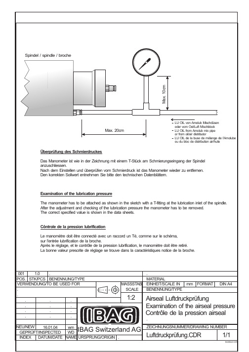
进口瑞士变频器说明书6_Examination of the lubrication pressure

001 1.0 . POS. STK/PCS BENENNUNG/TYPE VERWENDUNG/TO BE USED FOR . . . . . . . . . . . . . . NEU/NEW 16.01.04 wm GEPRÜFT/INSPECTED WD INDEX DATUM/DATE NAME URSPRUNG/ORIGIN .
Spindel / spindle / broche
Max. 10cm
Max. 20cm
LU OIL von Amolub Mischdüsen oder vom Oel/Luft Mischblock LU OIL from Amolub mix pipe or from oil/air distributor LU OIL de la buse de mélange de l’Amolube ou du bloc de distribution air/huile
MASSSTAB SCALE
. MATERIAL EINHEIT/SCALE IN mm FORMAT BENENNUNG/TYPE
DIN A4
1:2
Airseal Luftdruckprüfung Examination of the airseal pressure Contrôle de la pression airseal
Überprüfung des Schmierdruckes Das Manometer ist wie in der Zeichnung mit einem T-Stück am Schmierungseingang der Spindel anzuschliessen. Nach dem Einstellen und überprüfen vom Schmierdruck ist das Manometer wieder zu entfernen. Den korrekten Sollwert entnehmen Sie bitte den technischen Datenblättern.
IS5说明书

z 不要使用绝缘层已经破损的电缆。 否则,你可能受到电击。
z 不要使电缆受到擦伤,挤压,超电压和过负载。 否则,你可能受到电击。
1
注意
9 变频器要安装在不易燃的表面,附近不要放置可燃性材料。 否则可能发生火灾。 9 如果变频器受到损坏,立刻断开输入电源。 否则可能导致设备的二次损坏和火灾。 9 输入电源存在或断开后,变频器残存的热量还会保持几分钟。 否则,你可能受到身体伤害(例如:皮肤烧伤或伤害)。 9 不要给已经受损的或零件缺少的变频器通电,即使安装已经完成。 否则可能发生电击。 9 不允许麻布,纸屑,木屑,灰尘,金属碎片或其他杂物体进入变频器。 否则可能发生火灾或意外事故。
器变热与损坏。
参数初始化后,在运行前需要再次设定参数。当参数被初始化后,参数值又重新回到出厂设置。 变频器可以容易地设定为高速运行,在运行前先检查一下电机或机械设备的容量。 使用直流制动功能时,不会产生停止力矩。当需要停止力矩时,安装单独设备。 当驱动 400V 变频器和电机时,用绝缘整流器和采取措施抑制浪涌电压。由于在电机接线端子配线常数
<10Ω)。
检查或安装时,在触摸印刷电路板前注意保护措施(静电放电)。 在下列环境条件下使用变频器:
环境
环境温度 湿度 储存温度 安装场所 海拔, 振动 大气压力
- 10 ~ 40 ℃ (无冰冻) 90% RH 或更低 (无凝露) - 20 ~ 65 ℃ 无腐蚀性气体,可燃性气体,油雾或灰尘 最大海拔高度 1,000m 以下,最大 5.9m/sec2 (0.6G) 或更低 70~106kP
z 接线
不要安装电力电容器,浪涌抑制器,或 RFI 滤波器在变频器的输出侧。 连接到电机的输出电缆(U, V, W) 的连接方式将会影响到电机的旋转方向。 不正确的端子接线可能引起设备的损坏。 端子的正负极接反可能会损坏变频器。 只有受过专业培训的人才可以对变频器进行接线和检查。 先安装变频器再进行接线,否则,你可能受到电击或人身伤害。
变频器操作说明ppt课件

6
DATA/ENTER 确定方式,功能,参数,设
↙
定值பைடு நூலகம்,按此键。
(数据/输入)
RUN (运行键)
用操作器运行时,按此键变 频器开始运行。
STOP (停止键)
用操作器运行时,按此键变 频器停止运行。
用控制回路端子运行的场合, 根据参数o2-02的设定可以设 定该参数有效/无效。
最新课件
7
关于变频器模式的说明:
入下一个ADV程序模式,如此循环。
如果确定要进入某一种模式,则在该
模式的指示灯闪烁时按一次↙键,则指
示灯保持点亮状态而不再闪烁。此时
可以进一步修改具体的参数。
最新课件
10
参数设定操作实例:
要将参数c1-02(减速时间)从10秒变更 到5秒的设定顺序。 1:接通电源,数字操作器显示“F
0.0”。 2:按下MENU键,选择驱动模式,
少键确定数值大小。此例中按减少键 变更参数为5.00秒。
9:参数设定后,按下↙键确定,变频 器会显示END,表示参数成功设定完 毕。
10:按ESC键,返回。最后按MENU键 返回到驱动模式。
最新课件
13
具体的各个参数代表的含义需要查阅 有关的用户手册。
出现故障变频器会显示相应的错误码, 查阅用户手册以排除故障。
自学习模式:如果要让不知道电机 参数的电机进行矢量控制模式运行 时,自动计算、设定电机参数。也 可以只测定电机线间电阻。
最新课件
9
变频器只有在驱动模式下才可以运行, 在其它模式下主要完成参数的设定和 修改。
模式的切换
按MENU键选择操作模式,例如进入
到QUICK程序模式时,对应的LED指
示灯开始闪烁,继续按MENU键则进
欧陆EV500变频器使用手册第5章 功能参数详细说明

27-28
保留
9
正转点动控制
29
内部计数器时钟端
10
反转点动控制
30
外部脉冲输入
11
频率递增控制(UP)
31
长度计数输入(对X7端子)
12
频率递减控制(DW)
32
保留
13
频率设定通道选择端1
33
RST
14
频率设定通道选择端2
34
FWD
15
频率设定通道选择端3
35
REV
16
简易PLC暂停控制
17
三线式运转控制
18
直流制动控制
多段速与PLC切换功能,无效时,PLC优先级高,多段速低,有效时,多段速优先级高,PLC低。
PLC状态清零功能,停机时才有效,两个作用:一个是清除EEPROM中的纪录;另一个是清除当前PLC运行状态,再次启动,从第一段开始。
定义模拟输入电压通道V1的范围,应根据接入信号的实际情况设定。输入校正系数用于对输入电压进行校正,在组合设定方式下可改变本通道的权系数。
定义脉冲输入通道的脉冲频率范围,应根据接入信号的实际情况设定。输入校正系数用于对脉冲输入频率进行校正,在组合设定方式下可改变本通道的权系数。
这些参数用来规定外部输入量与设定频率的对应关系。
- 1、下载文档前请自行甄别文档内容的完整性,平台不提供额外的编辑、内容补充、找答案等附加服务。
- 2、"仅部分预览"的文档,不可在线预览部分如存在完整性等问题,可反馈申请退款(可完整预览的文档不适用该条件!)。
- 3、如文档侵犯您的权益,请联系客服反馈,我们会尽快为您处理(人工客服工作时间:9:00-18:30)。
HF 120.2 DI 36 C_e.doc 31.07.14 / sk
Spindle type: HF 120.2 DI 36 C
Type of bearings:
Ceramic ball bearings, oil-air lubricated
Characteristic U/f:
380 V ===> 1000 Hz
Motor: B40.530 380 V ===> 1400 Hz Typ: x
N°.of poles ===> 4 Nominal current: I n = 32A Peak current: I s = 44 A
Connections on spindle
Connection
N°. Dimension Colour Connector
Motor power EC 1 ø12.2 4x4mm² shield. orange PUR Cable lead-in PG
PTC SE1 1 ø5.4 7x0.14m m² grey PUR Cable lead-in PG Water WA 2 ø8-6 blue Quick connect Lubrication front LF1/2 2 ø4-2 transp. Quick connect Lubrication rear LR1 1 ø6-4 transp. Quick connect Airseal AS
1
ø6-4 green Quick connect Lubrication return LRET1/2 2 ø8-6 yellow
Quick connect
Motorspindel Motor Spindle
Broche à moteur
...\Data_Sheets\Motor_Spindles\HF_120\120AI36\HF1202AI36-42000.doc 1 / 1 23. April 2014 / fm
Leistungs- und Drehmomentdiagramm HF 120.2 AI 36
S1: 32A/380V
Power- and Torque-Diagram
Diagramme de puissance et couple
L e i s t u n g P o w e r P u i s s a n c e
D r e h m o m e n t T o r q u e C o u p l e W e r t e V a l u e s V a l e u r s
n x 1000 [min-1/RPM]
29.8 39.7 41.9 P [kW]
S1
13 13 13 S6-40% 16.9 16.9 16.9 M [Nm]
S1
4.2 3.1 3 S6-40%
5.4 4.1 3.9
B40-530
HF 120.2 DI 36 C_e.doc 31.07.14 / sk
Medias for spindle HF 120.2 DI 36 C
Spindle cooling: Cooling water Water with cooling concentrate
additive
Pressure cooling water: bar 2.5 Cooling water flow WA : l/min 10 Temp. cooling water: °C 24-28
Lubrication ball-bearings: oil-air Air pressure: bar 5
from maintenance unit, filtered air (5µm) and dry air, line length 5m,
Ø 4mm
Air pressure LF1/2: bar 4 / 4 measured at spindle lubrication inlet Air pressure LR1: bar 1 measured at spindle lubrication inlet Air flow LF1/2: l/min 20 / 18
Air flow LR1: l/min 60 Air pressure control: bar 4.5 Set point
Oil pressure: bar 20 IBAG AMOLUB, before dosage unit Oil quantitiy: cm 3
/h 0.2 per lubrication point
Pump time (enable): s 10 IBAG AMOLUB (DIS. TIME) Interval time (disable): s 180 IBAG AMOLUB (INT. TIME)
Pressure air seal: bar 2.5 from maintenance unit bar min. 1 measured at spindle inlet Flow air seal AS : l/min 84。
