LA2000_sc手册
MSA2000简易管理手册v1.0
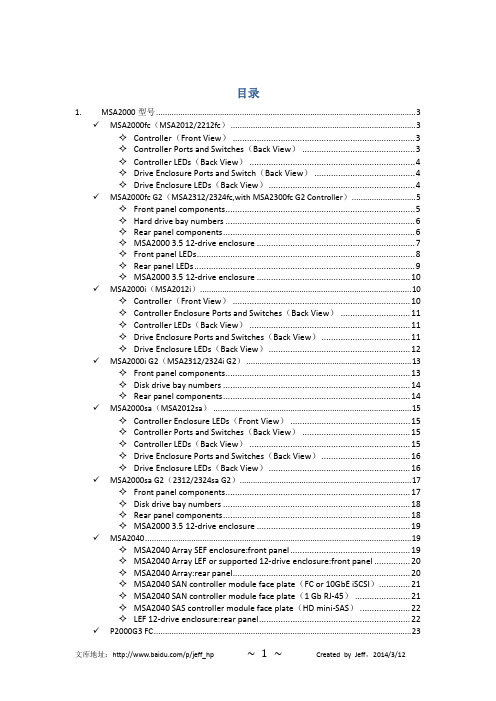
目录1. MSA2000型号 (3)✓MSA2000fc(MSA2012/2212fc) (3)✧Controller(Front View) (3)✧Controller Ports and Switches(Back View) (3)✧Controller LEDs(Back View) (4)✧Drive Enclosure Ports and Switch(Back View) (4)✧Drive Enclosure LEDs(Back View) (4)✓MSA2000fc G2(MSA2312/2324fc,with MSA2300fc G2 Controller) (5)✧Front panel components (5)✧Hard drive bay numbers (6)✧Rear panel components (6)✧MSA2000 3.5 12-drive enclosure (7)✧Front panel LEDs (8)✧Rear panel LEDs (9)✧MSA2000 3.5 12-drive enclosure (10)✓MSA2000i(MSA2012i) (10)✧Controller(Front View) (10)✧Controller Enclosure Ports and Switches(Back View) (11)✧Controller LEDs(Back View) (11)✧Drive Enclosure Ports and Switches(Back View) (11)✧Drive Enclosure LEDs(Back View) (12)✓MSA2000i G2(MSA2312/2324i G2) (13)✧Front panel components (13)✧Disk drive bay numbers (14)✧Rear panel components (14)✓MSA2000sa(MSA2012sa) (15)✧Controller Enclosure LEDs(Front View) (15)✧Controller Ports and Switches(Back View) (15)✧Controller LEDs(Back View) (15)✧Drive Enclosure Ports and Switches(Back View) (16)✧Drive Enclosure LEDs(Back View) (16)✓MSA2000sa G2(2312/2324sa G2) (17)✧Front panel components (17)✧Disk drive bay numbers (18)✧Rear panel components (18)✧MSA2000 3.5 12-drive enclosure (19)✓MSA2040 (19)✧MSA2040 Array SEF enclosure:front panel (19)✧MSA2040 Array LEF or supported 12-drive enclosure:front panel (20)✧MSA2040 Array:rear panel (20)✧MSA2040 SAN controller module face plate(FC or 10GbE iSCSI) (21)✧MSA2040 SAN controller module face plate(1 Gb RJ-45) (21)✧MSA2040 SAS controller module face plate(HD mini-SAS) (22)✧LEF 12-drive enclosure:rear panel (22)✓P2000G3 FC (23)✧Front panel components (23)✧Disk drive bay numbers (24)✧Rear panel view – controller module (24)✧Rear panel components (25)✧P2000 6Gb 3.5 12-drive enclosure (25)✧MSA2000 3Gb 3.5 12-drive enclosure (26)✓P2000G3 iSCSI (27)✧Front panel components (27)✧Disk drive bay numbers (28)✧Rear panel views – controller modules (28)✧Rear panel components (29)✧P2000 6Gb 3.5 12-drive enclosure (30)✧MSA2000 3Gb 3.5 12-drive enclosure (30)✓P2000G3 SAS (31)✧Front panel components (31)✧Disk drive bay numbers (32)✧Rear panel view – controller module (32)✧Rear panel components (33)✧P2000 6Gb 3.5 12-drive enclosure (33)✧MSA2000 3Gb 3.5 12-drive enclosure (34)2. MSA2000管理方式 (35)✓SMU(Web) (35)✧默认用户的设置 (35)✧管理端口默认IP地址 (35)✓CLI(串口) (35)✓ftp(ftp) (35)3. MSA2000日志收集 (36)✓SMU(Web方式) (36)✓CLI(命令行方式) (36)✓ftp(ftp方式) (36)1.MSA2000型号✓MSA2000fc(MSA2012/2212fc)✧Controller(Front View)✧Controller Ports and Switches(Back View)✧Controller LEDs(Back View)✧Drive Enclosure Ports and Switch(Back View)✧Drive Enclosure LEDs(Back View)✓MSA2000fc G2(MSA2312/2324fc,with MSA2300fc G2 Controller)✧Front panel components✧Hard drive bay numbers✧Rear panel componentsMSA2000 3.5 12-drive enclosure✧MSA2000 3.5 12-drive enclosure✓MSA2000i(MSA2012i)✧Controller(Front View)✧Controller Enclosure Ports and Switches(Back View)✧Controller LEDs(Back View)✧Drive Enclosure Ports and Switches(Back View)Drive Enclosure LEDs(Back View)✓MSA2000i G2(MSA2312/2324i G2)✧Front panel components✧Disk drive bay numbers✧Rear panel components✓MSA2000sa(MSA2012sa)✧Controller Enclosure LEDs(Front View)✧Controller Ports and Switches(Back View)✧Controller LEDs(Back View)✧Drive Enclosure Ports and Switches(Back View)✧Drive Enclosure LEDs(Back View)✓MSA2000sa G2(2312/2324sa G2)✧Front panel components✧Disk drive bay numbers✧Rear panel components✧MSA2000 3.5 12-drive enclosure✓MSA2040✧MSA2040 Array SEF enclosure:front panel✧MSA2040 Array LEF or supported 12-drive enclosure:front panel✧MSA2040 Array:rear panel✧MSA2040 SAN controller module face plate(FC or 10GbE iSCSI)✧MSA2040 SAN controller module face plate(1 Gb RJ-45)✧MSA2040 SAS controller module face plate(HD mini-SAS)✧LEF 12-drive enclosure:rear panel✓P2000G3 FC✧Front panel components✧Disk drive bay numbers✧Rear panel view – controller module✧Rear panel components✧P2000 6Gb 3.5 12-drive enclosureMSA2000 3Gb 3.5 12-drive enclosure✓P2000G3 iSCSI✧Front panel components✧Disk drive bay numbers✧Rear panel views – controller modulesRear panel components✧P2000 6Gb 3.5 12-drive enclosure✧MSA2000 3Gb 3.5 12-drive enclosure✓P2000G3 SAS✧Front panel components✧Disk drive bay numbers✧Rear panel view – controller module✧Rear panel components✧P2000 6Gb 3.5 12-drive enclosureMSA2000 3Gb 3.5 12-drive enclosure2.MSA2000管理方式✓SMU(Web)✧默认用户的设置✧管理端口默认IP地址10.0.0.2/255.255.255.0(控制器A)10.0.0.3/255.255.255.0(控制器B)✓CLI(串口)使用MSA2000专用micro-DB9串行电缆,波特率115200 ✓ftp(ftp)3.MSA2000日志收集✓SMU(Web方式)✓CLI(命令行方式)show systemshow usersshow controller-dateshow snmp-parametershow ntp-statusshow volume-mapsshow schedulesshow hostsshow advanced-settingsshow disksshow vdisksshow portsshow hostsshow volumesshow volumes-mapsshow network-parametersshow controllersshow versionsshow licenseshow configurationshow enclosuresshow enclosure-statusshow eventsshow frus✓ftp(ftp方式)参考命令:get logs 20140310_ftp_Storage2_A.txt。
LN2000软件手册

过程控制站可采用冗余配置,无论是板级还是网络的冗余均为热备份的方 式,当运行设备出现故障时,系统将无须人工介入自动切换至热备用设备,并 通过工程师站或操作员站的监视画面显示出故障设备,提醒运行维护人员进行 必要处理,而使系统在个别设备发生故障时,仍能维持原有功能稳定运行,冗 余技术的采用大大提高了系统的可靠性和无故障运行时间。 重要信号采取三取二的处理方法
1.3.2 采用技术方面
巧妙利用通用技术 在 LN2000 系统中大量的采用了当代新型的通用技术,如:通用计算机、 操作系统(WINDOWS2000)、SQL 数据库等,使它具有十分丰富的可利用的 技术资源和简单易学的特点。另外,它也能够不断跟上更新技术的发展,补充 它的性能。 广泛采用标准化技术 LN2000 系统把一大批成熟的标准技术作为整个系统的基础。这些技术包 括:IEEE802.2 以太网通信结构及协议;符合 ISA 的图形结构和界面;标准计 算机接口及总线等,使系统能够十分容易与其它系统连接和系统更新。 大力推广新型技术 LN2000 系统把计算机技术、窗口技术、控制技术、网络技术等十分有效地 融合在一起,尤为重要的是把仿真技术与上述技术密切结合,大大方便了系统 设计与调试,使它具有友好的人机界面和优秀的过程控制功能,从而能够后来 居上,成为值得信赖的分散控制系统。
LN2000 分散控制系统 软件使用说明书
山东鲁能控制工程有限公司 2001 年 9 月
第一篇 系统综述
1. 概述
1.1 引言
LN2000 系统是山东鲁能控制工程公司新近推出的一种新型的分散控制系 统(DCS)。它继承和发扬了当今 DCS 的优点:控制功能分散、系统功能分散 及显示、操作、记录、管理集中的功能,而且更注意借助世界上先进的多种技 术如:计算机技术、CRT 图形显示技术、数据通信技术、先进和现代控制技术, 通过技术创新,形成了系统结构合理、控制功能完善的开放的新型分散控制系 统,集数据采集、过程控制、生产管理于一体,能够满足大、中小不同规模的 生产过程的控制和管理需求。
阿尔法拉罐蒸发机Optigo CS用户手册说明书

CS200CS300• Product description• Product labels• Unpacking & lifting• Installation• Maintenance• Spare parts ORIGINAL INSTRUCTIONSIndex1. Important information1.1 Disclaimer (3)1.2 Intended use (3)1.3 Where to find product information (3)2. Product description2.1 General information and application (4)2.2 Standard configuration (4)2.3 Options (5)2.4 Code description (5)3. Product labels (6)4. Unpacking and lifting (8)5. Installation5.1 Mounting (9)5.2 Drain line (11)5.3 Refrigerant connections (11)5.4 Electrical connections (12)6. Maintenance6.1 Fan replacement (14)6.2 Driptray and side covers (14)6.3 Defrost heater elements replacement (14)6.4 Spare parts (15)1 Important information1.1 DisclaimerThis Instruction Manual applies to all Alfa Laval Optigo CS air cooler products and is supplied in combination with the Alfa Laval Air Cooler Product Manual AHE00042. Both manuals must be carefully examined and instructions should be followed up at all times. Alfa Laval does not accept liability for any damage resulting from non-compliance to the instructions as given in the manuals and order-related documents.1.2 Intended useAir coolers are partly completed machinery according to Machine Directive 2006/42/EC and intend-ed for incorporation in cooling systems. Declarations of Incorporation are available on . The units may not be put into operation until the conformity of the complete machine or cooling system has been declared according to the following standards and directives:• Pressure Equipment Directive 2014/68/EU• Machine Directive 2006/42/EC• Low Voltage Directive 2014/35/EU• Electrical Equipment of Machines IEC 60204-1• Electro Magnetic Compatibility 2014/30/EU• Any applicable local or national legislation1.3 Where to find product informationDetailed technical data for individual product models are available in order related documents, on the product label and in product data sheets. Comprehensive technical information for all Alfa Laval air heat exchanger products is available on-line on . This includes:• Product manuals Array• Instruction manuals• Product leaflets & brochures• Product data sheets (selection software)• Dimensional drawings• Electrical wiring diagrams• CertificatesOptigo CSAlfa Laval offers world-wide service and support in over 55 countries. In case of any questionsor uncertainty please contact your local Alfa Laval representative. Contact addresses are available at .2 Product description2.1 General information and applicationOptigo CS are commercial slim line air coolers for general application in small to medium-sized cooling and freezing rooms. CS200 are mini coolers with capacities up to 1.8 kW (SC2), whereas the CS300 line has a different casing geometry and offers cooling capacities up to 6.8 kW (SC2). All CS models are characterised by a low silhouette (only 15 cm for CS200) for the efficient use of cold room space.• Refrigerants: HFO/HFC DX refrigerants (CSE) and CO2 DX (CSX)• Room temperatures: +10 to -30 °C• Capacity range (SC2): 550 up to 6850 W• Air volume: 380 up to 3800 m3/hModel Refrigerant Design pressure Test pressureCSX CO280 bar114 bar2.2 Standard configuration• Innovative coil manufactured from internally grooved Cu tubes, aluminium fins and dedicated thicker tubes for CO2 application. Tube pitch is 30x26 mm staggered, standard fin spac-ings 4 and 7 mm. All models fitted with a T-connection for better refrigerant distribution. This T-connection is also suitable as a hot gas defrost connection.• Standard fitted with plug-in dual fan speed EC motors in two diameters (200 and 300 mm).Power supply 230/50-60/1.• Durable aluminium alloy casing, white epoxy coated RAL 9002. Hinged driptray construction, inspection panel for CS200 and removable side panels for CS300. Sufficient room for mount-ing of expansion valve inside casing. Pre-cut passages for multiple choice connections on both sides and top.• All Optigo CS models are delivered in wood-reinforced cardboard boxes, suitable for safe stack-ing.2.3 Options• Electric defrost (E)For cold rooms with room temperatures below 4 °C and frost build-up is likely, the application ofa defrosting system is advised. Electric defrost for Optigo CS consists of stainless steel heaterelements mounted against the bottom plate of the coil. The defrost element can be accessed after opening the driptray. The defrost element are connected to separate terminals in the termi-nal box. Electric defrost is mounted as default for 7 mm models, optional as a separate kit for 4 mm models.2.4 Code descriptionCS E H202B S230V BO AL E CB-AL7.0CU 1234567891011121314151 Commercial unit cooler - slim line2 Refrigerant system (E=HFO/HFC DX, X=CO2 DX)3 Fan speed (H=high speed, L=low speed)4 Fan diameter (20=200, 30=300 mm)5 Number of fans (1 to 5)6 Tube rows code (B, C)7 No. of phases (S=1)8 Motor voltage9 Packing (BO=box)10 Casing material (AL=epoxy coated aluminium)11 Defrost system (E=electric defrost, blank=air defrost)12 Connection box (CB)13 Fin material (AL=aluminium)14 Fin spacing (4.0, 7.0 mm)15 Tube material (CU=copper)3 Product labelsUnit Net Weight: 7,250 Kg ±5%Motorfan data:E XA 1. Product labelModel Refer to paragraph "CodeCS20CS30⑪3.Nitrogen precharge warningUnits are delivered from the manufacturerwith an overpressure. Check pressure on theSchrader valve. With unpressurised unit: imme-diate report to manufacturer and note on the billof delivery.6.Fan motorFan motor item number.7.Electrical warningElectrically powered component. Switch offpower supply before any maintenance or instal-lation activity.8.Fan directionSticker indicates fan rotation direction.9.Moving partsWarning: moving parts.Switch off power supply before any maintenanceor installation activities.4/5. In/OutRefrigerant connections inlet and outlet.10.EuroventSticker is applied when the product is included inthe Eurovent Certify All program.AP 5002826Coil PED data: I12 mmXAMP2.Product label - coilModel Refer to paragraph "CodeAlways follow guidelines and instructions as given in the air cooler product manual AHE00042.Optigo CS air coolers are delivered in a reinforced cardboard box. For CS300 models this box is fixed on a wooden support pallet. Handling and positioning can take place manually. When more than one cooler units are delivered in a single shipment, packed air coolers may be stacked during transportation.Open cardboard box and take out cooler unit.max. 10max. 4Respect the maximum number of stacked air cooler units.Additional box content:• Drilling mould (1x, CS200 only)• Manual• PVC driptray drain connection •Cu tube bends for 90° refrigerant in/out connections (2x, CS200 only)4 Unpacking and liftingCS200CS300max. 5max. 2CS200CS300Drawings showing all required mounting and refrigerant connectiondimensions are available for download on .Dimensional drawings5 InstallationAlways follow guidelines and instructions as given in the air cooler product manual AHE00042.5.1MountingCS200DimensionsConnectionsLength MountingShipping OD in/out LM volume CSE CSX model mm mm m 3mm mm 305C286524700.7616/2212/14CS200CS300Use drilling mould to mark mounting positions (included for CS200 only).Fix cooler unit to the ceiling using the fixingmaterials provided. Use extra wide washers (ISO 7093) when mounting the unit to the ceiling.For CS200 the integrated fan plate/driptray must be opened to access the fixing points.Mount PVC driptray drain. Tighten by hand only.Remove the plastic strips that secure the EC fan unit during transport and handling. The air cooleris now ready to be installed.5.2 Drain lineThe drain line diameter must be at least the size of the driptray drain diameter and should be laid with an adequate slope. For room temperatures below 0° C drain line insulation and defrosting are required.A syphon must be installed on the drain line, outside the cold room.Tighten drain connection by hand only.5.3 Refrigerant connectionsNever bend the air cooler refrigerant connection tubes. Bends in refrigerant pipework are only allowed in the external piping section.For both CS200 and CS300 there is sufficient space for mounting the expansion valve inside the cooler casing. Casing cutaways available onall cooler sides for refrigerant piping.Electrical connections5.4 Electrical connectionsThe following data determine which connection diagram is to be selected and respected for electrical installation:•Heat exchanger model indication •Electrical optionsE lectrical connection diagrams are available for download on. When in doubt always contact your local supplier or Alfa Laval representative for assistance.Electrical connections 2-speed EC fan motorsOpen the diptray and consequently the fan motor connection box. You will find the electric wiring diagram inside.High speed connectionConnect blue wire (N) to neutral.Connect black wire (L) to power supply.blackblueElectric defrost heater connection (optional)Electric defrost heatersHeater 230V/50-60HzPower model W CS201410CS3052700Low speed connectionConnect blue wire to neutral (N) and black wire to power supply (L).Open the orange clamps from the blue and brown wires.Create a jumper connection between the brown and the blue wires. This extra piece of cable is not supplied with the unit.brownblueblack6 MaintenanceEnsure complete electrical isolation before performing any maintenance activity and always follow guidelines and instructions as given in the air cooler product manual AHE00042.6.1Fan replacementUnplug power cable. Unscrew fixing bolts and remove old fan. Mount new fan in identicalposition. Use an anti-corrosion compound when remounting the fixing bolts.Replace power cable connector when the newfan has been mounted.6.2 Driptray and side coversDriptrays can be opened for inspection, cleaning and maintenance purposes. Always disconnect drain line before opening the driptray.Prior to opening, run a full defrost cycle to remove any ice in the driptray. Ensure the drip-tray is empty before opening. The weight of any leftover water could injure the service operator if the driptray fell open accidentally.Both CS200 and CS300 models are fitted with an integrated fan plate/driptray. To open this driptray, first loosen screws 'c' (CS300 only) and remove bolts 'a'. Then lower the driptray. Respect the maximum opening angle (90°) to avoid damage to the driptray hinges.For CS300 models, side covers can be removed for inspection, cleaning and maintenance pur-poses. To remove side covers, open driptray and loosen fixing screws 'b'. CS200 models are fitted with a removable side hatch to access the expension valve.6.3Defrost heater elements replacementThe replacement procedure for defrost heater elements is identical for all Optigo CS models.To replace defrost elements, open integrated fan plate/driptray, remove coil bottom plate and take defrost heater element out of its slots.Mount new element in reverse order and restoreelectrical connections as originally set.7 Spare partsSpare parts can be selected and ordered in the online eBusiness tool Alfa Laval Anytime. If required please contact your local Alfa LavalRepresentative for assistance.Alfa Laval AnytimeSpare parts for Optigo CS CS200CS300②①③②①③。
罗宾康说明书5

LA2000执行机构安装和使用注意事项
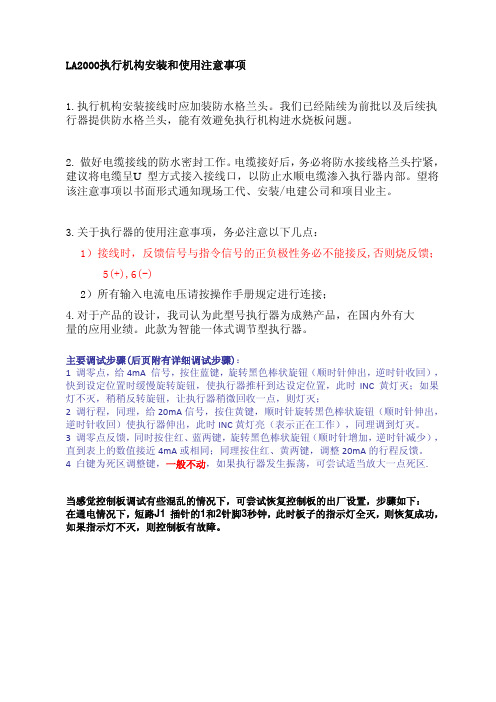
LA2000执行机构安装和使用注意事项1.执行机构安装接线时应加装防水格兰头。
我们已经陆续为前批以及后续执行器提供防水格兰头,能有效避免执行机构进水烧板问题。
2. 做好电缆接线的防水密封工作。
电缆接好后,务必将防水接线格兰头拧紧,建议将电缆呈U 型方式接入接线口,以防止水顺电缆渗入执行器内部。
望将该注意事项以书面形式通知现场工代、安装/电建公司和项目业主。
3.关于执行器的使用注意事项,务必注意以下几点:1)接线时,反馈信号与指令信号的正负极性务必不能接反,否则烧反馈;5(+),6(-)2)所有输入电流电压请按操作手册规定进行连接;4.对于产品的设计,我司认为此型号执行器为成熟产品,在国内外有大量的应用业绩。
此款为智能一体式调节型执行器。
主要调试步骤(后页附有详细调试步骤):1 调零点,给4mA 信号,按住蓝键,旋转黑色棒状旋钮(顺时针伸出,逆时针收回),快到设定位置时缓慢旋转旋钮,使执行器推杆到达设定位置,此时INC 黄灯灭;如果灯不灭,稍稍反转旋钮,让执行器稍微回收一点,则灯灭;2 调行程,同理,给20mA信号,按住黄键,顺时针旋转黑色棒状旋钮(顺时针伸出,逆时针收回)使执行器伸出,此时INC黄灯亮(表示正在工作),同理调到灯灭。
3 调零点反馈,同时按住红、蓝两键,旋转黑色棒状旋钮(顺时针增加,逆时针减少),直到表上的数值接近4mA或相同;同理按住红、黄两键,调整20mA的行程反馈。
4 白键为死区调整键,一般不动,如果执行器发生振荡,可尝试适当放大一点死区.当感觉控制板调试有些混乱的情况下,可尝试恢复控制板的出厂设置,步骤如下:在通电情况下,短路J1 插针的1和2针脚3秒钟,此时板子的指示灯全灭,则恢复成功,如果指示灯不灭,则控制板有故障。
短路J1 的1&2针脚调试步骤:1、电源:通电前,一定要确认开关SW1置于与输入电源(执行器铭牌额定电压)一致的位置,否则有可能导致控制板损坏或不能正常工作。
ART2000用户手册

3. 网络服务平台包含服务器程序模块、WEB 发布程序模块、以及平台 支持软件。
-1-
4. PDA 操作平台是通导 PDA 加近距离无线通讯模块,与智能控制模块 进通讯,完成以开关的操作控制。
-9-
- 10 -
- 11 -
- 12 -
- 13 -
- 14 -
- 15 -
- 16 -
- 17 -
- 18 -
- 19 -
- 20 -
- 21 -
- 22 -
第四部分 安装调试说明 一、 安装说明
1. 开关安装,见下图
- 23 -
2. 控制线与接地线安装,让航空头对口插好,拎紧航空头镙帽。注意联 接电缆有无破损。
三、 系统功能
开关的自动控制,手动控制功能。 开关运行历史数据采集、存储、查询功能。 开关定值整定功能。 开关数据 WEB 发布功能。 开关 GIS 定位功能。
第二部分 FTU 智能控制装置
一、 装置简介
ART2000 智能控制装置用于 10KV、6KV 柱上开关进行综合控制。它 可以就地手动控制、近距离无线遥控制、GPRS 网络控制开关分合。并有 线路全方位保护功能,是新一代智能电网的重要组成部分。
智能故障隔离重合器
用 户 手 册
本用户手册为智能故障隔离重合器官方文档,如您所使用的产 品根据特殊要求做了某些修改,本手册概不另述。本公司对手册所 有资料拥有相关权益。
西安卓立电力科技有限公司
第一部分 总述
一、 系统简介
现在国家智能电网正在大力推进,本系统可使 10KV 馈线通过智能开 关进行自动化控制。从而节约人力物力,并且提高电网系统可靠性。
RL00系列条码秤通用说明书
6.3.1 使用标签纸:(设置步骤) ......................................................................... 20
6.3.2 使用收据纸:(设置步骤) ......................................................................... 20
未经许可不得翻印、修改或引用。
METTLER TOLEDO 为梅特勒-托利多(常州)称重设备系统有限公司的注册商标。
警 告
1 .使用条形码电子计价秤前,必须仔细阅读本说
6.4 操作员的记入和记出............................................................................ 21
6.5 编程.......................................................................................... 22
三.简介.....................................................................................................8
3.1 基本功能....................................................................................... 8
一.安全使用提示.............................................................................................5
ML2000说明书
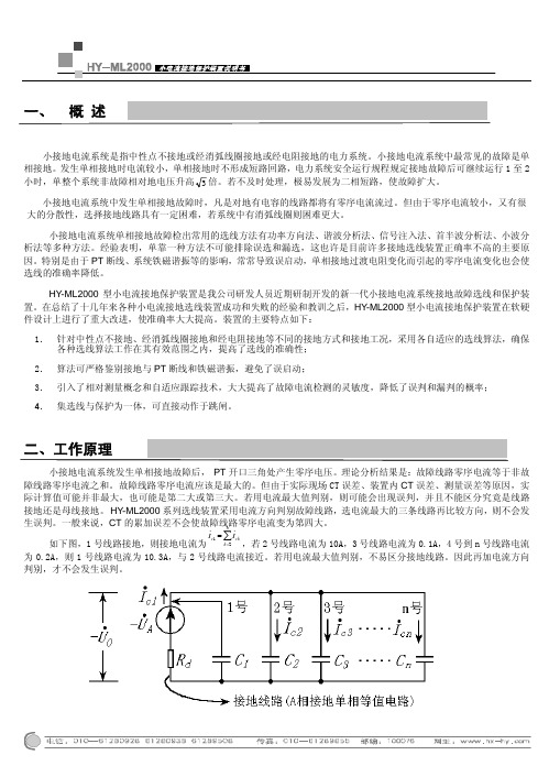
小接地电流系统是指中性点不接地或经消弧线圈接地或经电阻接地的电力系统。
小接地电流系统中最常见的故障是单相接地。
发生单相接地时电流较小,单相接地时不形成短路回路,电力系统安全运行规程规定接地故障后可继续运行1至2小时,单整个系统非故障相对地电压升高3倍。
若不及时处理,极易发展为二相短路,使故障扩大。
小接地电流系统中发生单相接地故障时,凡是对地有电容的线路都将有零序电流流过。
但由于零序电流较小,又有很大的分散性,选择接地线路具有一定困难,若系统中有消弧线圈则困难更大。
小接地电流系统单相接地故障检出常用的选线方法有功率方向法、谐波分析法、信号注入法、首半波分析法、小波分析法等多种方法。
经验表明,单靠一种方法不可能排除误选和漏选,这也许是目前许多接地选线装置正确率不高的主要原因。
特别是由于PT 断线、系统铁磁谐振等的影响,常常导致误启动,单相接地过渡电阻变化而引起的零序电流变化也会使选线的准确率降低。
HY-ML2000型小电流接地保护装置是我公司研发人员近期研制开发的新一代小接地电流系统接地故障选线和保护装置。
在总结了十几年来各种小电流接地选线装置成功和失败的经验和教训之后,HY-ML2000型小电流接地保护装置在软硬件设计上进行了重大改进,使准确率大大提高。
装置的主要特点如下:1.针对中性点不接地、经消弧线圈接地和经电阻接地等不同的接地方式和接地工况,采用各自适应的选线算法,确保各种选线算法工作在其有效范围之内,提高了选线的准确性; 2. 算法可严格鉴别接地与PT 断线和铁磁谐振,避免了误启动;3. 引入了相对测量概念和自适应跟踪技术,大大提高了故障电流检测的灵敏度,降低了误判和漏判的概率; 4. 集选线与保护为一体,可直接动作于跳闸。
小接地电流系统发生单相接地故障后, PT 开口三角处产生零序电压。
理论分析结果是:故障线路零序电流等于非故障线路零序电流之和。
故障线路零序电流应该是最大的。
但由于实际现场CT 误差、装置内CT 误差、测量误差等原因,实际计算值可能并非最大,也可能是第二大或第三大。
徕卡TPS2000简易操作手册

Instr.setup :Stability check
Compensator on/off 补偿器开关 ON 为开
Compensator: ON
Hz-corr 水平角改正开关 ON 为开
Hz-corr. : ON
OFF
关
4. EDM test <sigual/frequency> 测距回光信号及频率测试 F3(FREQ) 测量频率和回光信号强度显示状态的转换开关,80%以上时测距效果最好。 F5 (STOP) 结束并返回原对话框 F6 (ÆOFF) 回光信号音响开关
一行记录由一个或多个数据块组成。 例子:
110001+00000005 21.324+00000004 22.324+08545254 31..06+00044207 110002+00000007 21.324+00020034 22.324+09019410 31..06+00033750 110003+00000009 21.324+18019579 22.324+26942383 31..06+00033751
L2000射频导纳物位控制器说明书
灵敏度细调
灵敏度粗调
输出状出延 时指示
高低位 报警选择
+ 24 VDC
NC C NC NC C NC
NC C NC NC C NC
L2000-220VAC接线图
L2000-24VDC接线图
输出延 时指示
2
控制器外壳尺寸
L2000外壳尺寸图
探头尺寸(单位mm):
杆式标准探头L843
杆式防腐探头L843TS 注:防腐探头必须用法兰安装,法兰尺寸由用户自选,默认标准为DN15PN1.6。 杆式飞灰探头L853
杆式高温探头L864
注: 杆式高温陶瓷探头必须用法兰安装,石棉板隔热密封,法兰尺寸由用户自选, 默认标准为DN15PN1.6。 3
缆式探头L843W
缆式防腐探头L843TW
选型指南:
L2000 - XXX / XXX - XXmm - XXm
探头总长: 用户自选,标准为450mm, 杆式探头最长2.5米 缆式探头最长20米
保护套长: 用户自选,标准为150mm 以至少伸出容器内壁积料50mm为宜
探头型号: L843 (杆式标准探头) L843TS (杆式防腐探头) L853 (杆式飞灰探头) L864 (杆式高温探头) L843W (缆式标准探头) L843TW (缆式防腐探头) L890 (平板探头)
代理商:上海雄风自控工程有限公司 地址:上海市北青公路3585号 电话:86-21-39808151 传真:86-21-39808150 邮编:201705 网址:
Distributor Shanghai Xiongfeng Automation Control Engineering Co., Ltd. Address: No 3585, Beiqing Road, Shanghai Tel: 86-21-39808151 Fax: 86-21-39808150 Post Code: 201705 Web:
科力达电子经纬仪维修手册

科力达电子经纬仪维修手册科力达电子经纬仪操作手册2.5. 仪器与基座的装卸拆卸如有需要,仪器可从三角基座上卸下,先用螺丝刀松开基座锁定钮固定螺丝,然后逆时针转动基座锁定扭约180°,即可使仪器与基座分离.安装将仪器的定向凸出标记与基座定向凹槽对齐,把仪器上的三个固定脚对应放入基座的孔中,使仪器装在三角基座上,顺时针转动基座锁定钮约180°使仪器与基座锁定,再用螺丝刀将基座锁定钮固定螺丝旋紧.3. 键盘功能与信息显示3.1. 键盘符号与功能本仪器键盘具有一键双重功能,一般情况下仪器执行键上方所标示的第一(测角)功能,当按下MODE键后再按其余各键则执行按键下方所标示的第二(测距)功能.R/LCONS显示右旋/左旋水平角选择键.连续按此键,两种角值交替显示.专项特种功能模式键.HOLDMEAS水平角锁定键.按此键两次,水平角锁定;再按一次则解除.测距键.按此键连续精确测距(连接测距仪有效). 在特种功能模式中按此键,显示屏中的光标左移.0 SETTRK水平角置零键.按此键两次,水平角置零.跟踪测距键.按此键每秒跟踪测距一次,精度至0.01m(连接测距仪有效).在特种功能模式中按此键,显示屏中的光标右移. V% 竖直角和斜率百分比显示转换键.连续按此键交替显示.在测距模式状态时,连续按此键则交替显示斜距第一(键上)功能符号操作键第二(键下)功能符号信息显示窗口▲( ),平距( ),高差( ).增量键.在特种功能模式中按此键,显示屏中的光标可上下移动或数字向上增加.MODE▼测角,测距模式转换键.连续按键,仪器交替进入一种模式,分别执行键上或键下标示的功能.减量键.在特种功能模式中按此键,显示屏中的光标可上下移动或数字向下减少.REC望远镜十字丝和显示屏照明键.按键一次开灯照明;再按则关(若不按键,10秒后自动熄灭).记录键.令电子手簿执行记录.PWR 电源开关键.按键开机;按键大于2秒则关机.3.2. 信息显示符号液晶显示屏采用线条式液晶,常用符号全部显示时其位置如图所示:中间两行各8个数位显示角度或距离观测结果数据或提示字符串.左右两侧所示的符号或字母表示数据的内容或采用的单位名称.V 竖直角 % 斜率百分比H 水平角 G 角度单位:格(Gon)(角度采HR 右旋(顺时针)水平角用度及密位时无符号显示).HL 左旋(顺时针)水平角 m 距离单位:米斜距 ft 距离单位:英尺平距电池电量高差 (注:其余符号在本仪器中未采用.)4. 初始设置本仪器具有多种功能项目供选择,以适应不同作业性质对成果的需要.因此,在仪器使用前,应按不同作业需要,对仪器采用的功能项目进行初始设置.4.1. 设置项目(1) 角度测量单位:360°,400gon,6400mil(出厂设为360°).(2) 竖直角0方向的位置:水平为0°或天顶为0°(出厂设天顶为0°).(3) 自动断电关机时间为:30min(分钟)或10min(分钟) (出厂设为30min).(4) 角度最小显示单位:1〃或5〃(出厂设为1〃).(5) 竖盘指标零点补偿选择:自动补偿或不补偿(出厂设为自动补偿).(无自动补偿的仪器此项无效).(6) 水平角读数经过0°,90°,180°,270°象限时蜂鸣或不蜂鸣(出厂设为蜂鸣).(7) 选择不同类型的测距仪联接(出厂设为与科力达ND系联接).4.2. 设置方法(1) 按住CONS键打开电源开关,至三声蜂鸣后松开CONS 键.仪器进入初始设置模式状态,显示器显示:闪烁显示器下一行八个数位分别表示初始设置的内容如下:1 1 1 1 1 1 1 0至0 0 0 0 0 0 0 6(7)(6)(5)(4)(3)(2)(1)数位代码在显示器上行显示的设置内容设置内容字符代码ND 300011011111可与联接的测距仪型号0 S.2L 2A 索佳RED2L(A)系列1 ND3000 科力达,南方ND系列2 P.20 宾得MD20系列3 DI1600 徕卡系列4 S.2 索佳MINI2系列5 D3030 常州大地D3030系列6 TP.A5 拓普康DM系列1 90°BEEP 象限蜂鸣0 DIS.BEEP 象限不蜂鸣1 TLT.ON 竖盘自动补偿器打开0 TLT.OFF 竖盘自动补偿器关闭1 STEP 1 角度最小显示单位1〃0 STEP 5 角度最小显示单位5〃1 30 OFF 自动关机时间30min(分)0 10 OFF 自动关机时间10min(分)1 HOT =0 竖直角水平为0°0 HOT =90 竖直角天顶为0°11 359°59′59〃角度单位:360度01 399.99.99 角度单位:400格(G)00 6399.99 角度单位:6400密位10 359°59′59〃角度单位:360度(2) 按MEAS或TRK键使闪烁的光标向左或向右移动到要改变的数字位.(3) 按或键改变数字,该数字所代表的设置内容在显示器上行以字符代码的形式予以提示.(4) 重复⑵和⑶操作进行其它项目的初始设置直至全部完成.(5) 设置完成后按CONS键予以确认,仪器返回测量模式. l 设置完成后,一定要按CONS键予以确认,把设置存入仪器内,否则仪器仍保持原来的设置.5. 测量准备5.1. 仪器的安置,对中和整平安置三脚架和仪器(1) 选择坚固地面放置脚架之三脚,架设脚架头至适当高度,以方便观测操作.(2) 将垂球挂在三脚架的挂钩上,使脚架头尽量水平地移动脚架位置并让垂球粗略对准地面测量中心,然后将脚尖插入地面使其稳固.(3) 检查脚架各固定螺丝固紧后,将仪器置于脚架头上并用中心联接螺丝联结固定.使用光学对中器对中(1) 调整仪器三个脚螺旋使圆水准器气泡居中.通过对中器目镜观察,调整目镜调焦旋钮,使对中分划标记清晰.(2)调整对中器的调焦旋钮,直至地面测量标志中心清晰并与对中分划标记在同一成像平面内.(3) 松开脚架中心螺丝(松至仪器能移动即可),通过光学对中器观察地面标志,小心地平移仪器(勿旋转),直到对中十字丝(或圆点)中心与地面标志中心重合.(4) 再调整脚螺旋,使圆水准器的气泡居中.(5) 再通过光学对中器,观察在面标志中心是否与对中器中心重合,否则重复(3)和(4)操作,直至重合为止. (6) 确认仪器对中后,将中心螺丝旋紧固定好仪器.l 仪器对中后不要再碰三脚架的三个脚,以免破坏其位置.用长水准器精确整平仪器(1) 旋转仪器照准部让长水准器与任意两个脚螺旋连线平行,调整这两个脚螺旋,使长水准器气泡居中.调整两个脚螺旋时,旋转方向应相反(如图).(2) 将照准部转动90°,用另一脚螺旋使长水准器气泡居中.(3) 重复⑴和⑵,使长水准器在该两个位置上气泡都居中.(4) 在⑴的位置将照准部转动180°,如果气泡居中并且照准部转动至任何方向气泡都居中,则长水准器安置正确且仪器已整平.l 注意观察脚螺旋的旋转方向与气泡移动方向的关系.l 在⑷中,气泡若不居中,应校正长水准器,请参阅后面(8.1)的校正方法.5.2. 望远镜目镜调整和目标照准目镜调整(1) 取下望远镜镜盖.(2) 将望远镜对准天空,通过望远镜观察,调整目镜旋钮,使分划板十字丝最清晰.l 观察目镜时,眼睛应放松,以免产生视差和眼睛疲劳.当光亮度不足难以看清十字丝时,按照明键( )照明.目标照准(1) 用粗瞄准器的准星对准目标.(2) 调整望远镜调焦旋钮,直至看清目标.(3) 旋紧水平与垂直制动旋钮,微调两微动旋钮,将十字丝中心精确照准目标,这时眼睛左右上下轻微移动观察, 若目标与十字丝两影像间有相对移位现象,则应该再微调望远镜调焦旋钮,直至两影像清晰且相对静止时止.l 对较近目标调焦时,顺时针转动调焦旋钮.较远目标则逆时针方向旋转.l 若⑶未调整好,则视差会歪曲目标与十字丝中心的关系,从而导致观测误差.l 用微动旋钮对目标作最后精确照准时,应保持旋钮顺时针方向旋转.如果转动过头,最好返回再重新按顺时针方向旋转旋钮进行照准.l 即使不测竖直角,我们仍建议尽量用十字丝中心位置照准目标.5.3. 打开或关闭电源按键式电源开关操作显示按住PWR键至显示屏显示全部符号,电源打开.2秒后显示出水平角值,即可开始测量水平角.按PWR键大于2秒至显示屏显示OFF 符号后松开,显示内容消失,电源关闭.l 开启电源后显示的水平角为仪器内存的原角值,若不需要此值时,可用"水平角置零"l 若设置了"自动断电"功能,30或10分钟内不进行任何操作,仪器会自动关闭电源并将水平角自动存储起来.5.4. 指示竖盘指标归零(V 0 SET)操作显示开启电源后如果显示"b",提示仪器的竖轴不垂直,将仪器精确置平后"b"消失.仪器精确置平后开启电源ET系列显示"V 0SET"提示应指示竖盘指标归零.将望远镜在盘左水平位置上下转动1~2次,当望远镜通过水平视线时将指示竖盘指标归零,显示出竖盘角值.仪器可以进行水平角及竖直角测量.l 采用了竖盘指标自动补偿归零装置的仪器,当竖轴不垂直度超出设计规定时,竖盘指标将不能自动补偿归零,仪器显示"b",将仪器重新精确置平待"b"消失后,仪器方恢复正常.l 若设置了"自动断电"功能,30或10分钟内不进行任何操作,仪器会自动关闭电源并将水平角自动存储起来.6. 角度测量6.1. 盘左/盘右观测"盘左"是指观测者对着望远镜时,竖盘在望远镜的左边;"盘右"指的是观测者对着望远镜目镜时,竖盘在望远镜的右边(如图所示).取盘左和盘右读数的平均数作为观测值,可以有效地消除仪器相应的系统误差对成果的影响. 因此,在进行水平和竖直角观测时,要在完成盘左观测之后, 中转望远镜180°再完成盘右观测.盘左观测盘右观测6.2. 水平角置"0"(0 SET)将望远镜十字丝中心照准目标A后,按0 SET键两次,使水平角读数为"0°00′00〃".如:照准目标A显示为HR50°10′20〃→ 按两次0 SET键→ 显示目标A方向为HR 0°00′00〃l 0 SET键只对水平角有效.l 除已锁定HOLD键状态外,任何时候水平角均可置"0". 若在操作过程中误按0 SET键盘,只要不按第二次就没关系,当鸣响停止,便可继续以后的操作.6.3. 水平角与竖直角测量(HR,V或HL,V)(1) 设置水平角右旋与竖直角天顶为0°测量方式(HR.V).顺时针方向转动照准部(HR),以十字丝中心照准目标A,按两次0 SET键,目标A的水平角度设置为0°00′00〃, 作为水平角起算的零方向.照准目标A时的具体步骤及显示为:按两次→0 SET→顺时针方向转动照准部(HR),以十字丝中心照准目标B时显示为:B方向竖直角(天顶距)值AB方向间右旋水平角值V 93°20′30〃HR 10°50′40〃V 91°05′10〃HR 50°10′20〃A方向竖直角(天顶距)值A方向水平角已置"0"V 93°20′30〃HR 00°00′00〃(2) 按R/L键后,水平角设置成左旋测量方式(HL.V).逆时针方向转动照准部(HL),以十字丝中心照准目标A,按两次0 SET键将A方向水平角置"0".步骤和显示结果与(1)之A目标相同.逆时针方向转动照准部(HL),以十字丝中心照准目标B时显示为:B方向竖直角(天顶距)值AB方向间左旋水平角值l R/L键对竖直角无效.l 再按R/L键,水平角又由左旋转为右旋方式.l B方向观测完后可继续照准以后各方向,以获得各方向相应的水平角与竖直角值.l (1)和(2)仅列举了盘左观测时的步骤,接着应中转望远镜完成盘右的观测.6.4. 水平角锁定与解除(HOLD)在观测水平角过程中,若需保持所测(或对某方向需予置)水平角时,按HOLD键两次即可.水平角被锁定后,显示左下角"HRL"符号闪烁,再转动仪器水平角也不发生变化.当照准至所需方向后,再按HOLD键一次,解除锁定功能,此时仪器照准方向的水平角就是原锁定的水平角值. l HOLD键对竖直角或距离无效.l 若在操作过程中误按HOLD键,只要不按第二次就没有关系,当鸣响停止便可继续以后的操作.V R091°05′10〃HR 309°49′40〃6.5. 水平角象限鸣响设置(1) 照准定向的第一个目标,按0 SET键两次,使水平角置"0".(2) 将照准部转动约90°,至有鸣响时停止,显示:HR 89°59′20〃.(3) 旋紧水平制动旋钮,用微动旋钮使水平读数显示为:HR 90°00′00〃 ,用望远镜十字丝确定象限目标点方向.(4) 用同样的方法转动照准部确定180°,270°的象限目标点方向.6.6. 竖直角的零方向设置竖直角在作业开始前就应依作业需要而进行初始设置,选择天顶方向为0 或水平方向为0 .(方法参阅初始设置说明)两种设置的竖盘结构如图所示:l 当读数值经过0 ,90 ,180 ,270 各象限时,蜂鸣器鸣响,鸣响从上述值±1′范围开始至±20〃范围停止.l 鸣响可以在初始设置中取消.PDF 文件使用"pdfFactory" 试用版本创建/doc/785763222.html,科力达电子经纬仪操作手册·25·180°540°6.7. 天顶距与垂直角的测量(1) 天顶距:如竖直角选择天顶方向为0°,测得(显示)的竖直角V为天顶距,如图.天顶距=(L+360°-R)/2指标差=(L+R-360°)/2(2) 垂直角:如竖直角选择水平方向为0°,则测得(显示)的竖直角V为垂直角,如图.垂直角=(L±180°-R)/2指标差=(L+R- )/2l 若指标差|i| ≥10〃,则应按本书(8.5和8.6)介绍的方法进行检验与校正.6.8. 斜率百分比在测角模式下测量.竖直角可以转换成斜率百分比.按V%键,显示器交替显示竖直角和斜率百分比.斜率百分比值=H/D×100%PDF 文件使用"pdfFactory" 试用版本创建/doc/785763222.html,科力达电子经纬仪操作手册·26·斜率百分比范围从水平方向至±45°(±50G),若超过此值则仪器不显示斜率值.6.9. 望远镜视距丝测距利用望远镜分划板上的视距丝(上下或左右视距丝)可以测量目标与仪器间的距离,测量精度≤0.4%D.(1) 将仪器安置在A点,标尺竖立(平放)在目标B点.(2) 读出分划板在上下或左右两视距丝在标尺上的截距d.(3) AB两点之间的水平距离D= 100×d.l 此种测距精度不是很高,不可用此法测高精度的距离.7. 与测距仪及电子手薄联接组合成多功能全站仪ET—02/05/05B电子经纬仪有两个数据输入输出接口,可与多种类型的测距仪相联结组成全站仪,再与科力达电子手薄联接则可组成多功能全站仪.(如图)电子经纬仪与测距仪联接组合成全站仪(1) 将电子经纬仪提把的两个固定螺丝松开取下提把.(2) 将测距仪安装到电子经纬仪的连接柱上固紧螺丝.(3) 量取经纬仪与测距仪两横轴中心的间距,调整反射棱镜与觇板两中心的间距与之相一致.作业时,经纬仪视轴照准觇板中心,测距仪视轴照准棱镜中心,使两轴保持平行.(4) 电子经纬仪盘左时物镜侧斜下方接口是与测距仪联结的接口.本仪器与各型号的测距仪相联结时,应选用科力达CE—202系列相应的电缆,详见下表:CE—202 联科力达/南方ND系列测距仪CE—202P 联宾得测距仪CE—202L 联徕卡测距仪CE—202S 联索佳测距仪CE—202D 联常州大地测距仪CE—202T 联拓普康测距仪(5) 开机初始设置,按本书所述初始设置的方法,将所选用的测距仪型号设置为本仪器中使用的测距仪.与科力达测距仪和电子手簿联接(6) 按C O N S键确认初始设置,回到测量模式,盘左上下转动望远镜指示竖盘指标归零,仪器进入测角模式状态.(7) 按M O D E键进入测距模式状态.显示为:(8) 用经纬仪十字丝中心照准觇板中心,用测距仪照准棱镜中心,按测距仪上的测距键进行测距,这时,测距仪测的距离值就被自动显示到电子经纬仪上.如:(9) 连续按V%键,交替显示斜距 ,平距 ,高差 .电子经纬仪与科力达电子手簿的联接设置在仪器对中器目镜下侧的接口,可用科力达CE-201 电缆与科力达电子手簿联接,将仪器观测数据输入电子手簿进行记录.以上两项联接后就组成了能自动数据采集的多功能全站仪.与测距仪联机后的注意事项!l 反射棱镜和觇板两中心的间距应调整到与经纬仪和测距仪两横轴中心的间距相一致.l 作业中如需使用斜距和高差成果时,则在设置测点棱镜站时,应使棱镜中心至地面标志的高度与测站点测距仪中心至地面标志的高度相一致.若两者高度不一致,对所显示的斜距和高差则需计算不等高改正数并进行修正后方可使用(平距则不受影响).l 计算平距,高差时,对竖直角的要求应参阅各测距仪的说明,并按其要求对仪器竖直角的零方向进行初始设置. 科力达ND系列测距仪对竖直角要求采用天顶距.8. 检验与校正8.1. 长水准器检验方法见本书"5.1用长水准器精确整平仪器"一节.校正(1) 在检验的(4)位置,若长水准器的气泡偏离了中心,先用与长水准器平行的脚螺进行调整,使气泡向中心移近一半的偏离量.(2) 剩余的一半用校正针对水准器校正螺丝进行调整.(3) 将仪器旋转180°,检查气泡是否居中.如果气泡仍不居中,重复上述步骤,直至气泡居中.(4) 将仪器旋转90°,用第三个脚螺旋调整气泡居中.重复检验与校正步骤直至照准部转至任何方向气泡均居中为止.8.2. 圆水准器检验长水准器检校正确后,若圆水准器气泡亦居中就不必校正.校正若水泡不居中,用校正针或内六角搬手调整气泡下方的校正螺丝使气泡居中.校正时,应先松开气泡偏移方向对面的校正螺丝(1或2个),然后拧紧偏移方向的其余校正螺丝使气泡居中.气泡居中时,三个校正螺丝的紧固力均应一致.8.3. 望远镜分划板倾斜检验(1) 整平仪器后在望远镜视线上选定一目标点A,用分划板十字丝中心照准A并固定水平和垂直制动旋钮.(2) 转动望远镜垂直微动旋钮,使 A点移动至视场的边沿(A′点).(3) 若A点是沿十字丝的竖丝移动,即A′点仍在竖丝之内的,则十字丝不倾斜不必校正.如图,A′点偏离竖丝中心,则十字丝倾斜,需对分划板进行校正.校正(1) 首先取下位于望远镜目镜与调焦旋钮之间的分划板座护盖,便看见四个分划板座固定螺丝(见8.4的附图).(2) 用螺丝刀均匀地旋松该四个固定螺丝,绕视准轴旋转分划板座,使A′点落在竖丝的位置上.(3) 均匀地旋紧固定螺丝,再用上述方法检验校正结果.(4) 将护盖安装回原位.8.4. 视准轴与横轴的垂直度(2C)检验(1) 距离仪器同高的远处设置目标A,精确整平仪器并打开电源.(2) 在盘左位置将望远镜照准目标A,读取水平角(例: 水平角L=10°13′10〃).(3) 松开垂直及水平制动旋钮中转望远镜,旋转照准部盘右照准同一A点(照准前应旋紧水平及垂直制动旋钮)并读取水平角(例:水平角R=190°13′40〃). (4) 2C=L-(R±180°)= -30〃≥±20〃,需校正.校正(1) 用水平微动旋钮将水平角读数调整到消除C后的正确读数:R+C=190°13′40〃-15〃=190°13′25〃. (2) 取下位于望远镜目镜与调焦旋钮之间的分划板座护盖,调整分划板水平左右两个校正螺丝,先松一侧后紧另一侧的螺丝,移动分划板使十字丝中心照准目标A.(3) 重复检验步骤,校正至 |2C|<20〃符合要求为止.(4) 将护盖安装回原位.8.5. 竖盘指标零点自动补偿检验竖盘采用了液体电容式指标零点自动补偿装置的仪器, 指标零点是否能自动补偿,可用下述简要方法检验: (1) 安置和整平仪器后,使望远镜的指向和仪器中心与任一脚螺旋(X)的联线相一致,旋紧水平制动旋钮. (2) 开机后指示竖盘指标零点,旋紧垂直制动旋钮,仪器显示当前望远镜指向的竖直角值.(3) 朝一个方向慢慢转动脚螺旋(X)至10mm(圆周距)左右时,显示的竖直角由相应随着变化到消失出现"b"信息,表示仪器竖轴倾斜已大于3′,超出竖盘补偿器的设计范围.当反向旋转脚螺旋复原时,仪器又复现竖直角(在临界位置可反复实验观其变化),表示竖盘补偿器工作正常.校正当发现仪器补偿失灵或异常时,应送厂检修.l ET—05B型仪器无竖盘指标零点自动补偿装置,而在电池盒下方有一与仪器中间的长水准器相垂直的管水准器可作检验.该水准器的气泡位置正常与否的检验与校正参照8.1的操作.8.6. 竖盘指标差(i角)和竖盘指标零点设置在完成8.3和8.5的检验项目后再检验本项目.检验(1) 安置整平好仪器后开机,将望远镜照准任一清晰目标得竖直角盘左读数L.(2) 中转望远镜再照准A,得竖直角盘右读数R.(3) 若竖直角天顶为0°,则i=(L+R-360°)/2;若竖直角水平为0°,则i = (L+R-180°)/2或(L+R-540°)/2 (4) 若| i |≥10〃,则需对竖盘指标零点重新设置.校正(竖盘指标零点设置)(1) 整平仪器后,按住 V% 键开机,三声蜂鸣后松开按键,显示:V 0SETSET--1(2) 在盘左水平方向附近上下转动望远镜,待上行显示出竖直角后,转动仪器精确照准与仪器同高的远处任一清晰稳定目标A,按V%键,显示:V 90°20′30〃SET--2(3) 中转望远镜,盘右精确照准同一目标A, 按 V% 键,设置完成,仪器返回测角模式.(4) 重复检验步骤重新测定指标差(i).若指标差仍不符合要求,则应检查校正(指标零点设置)的(1)(2)(3)步骤的操作是否有误,目标照准是否准确等,按要求再重新进行设置.(5) 经反复操作仍不符合要求时,应送厂检修.l 零点设置过程中所显示的竖直角是没有经过补偿和修正的值,只供设置中参考不能作它用.8.7. 光学对中器检验(1) 将仪器安置到三脚架上,在一张白纸上画一个十字交叉并放在仪器正下方的地面上.(2) 调整好光学对中器的焦距后,移动白纸使十字丝交叉位于视场中心.(3) 转动脚螺旋,使对中器的中心标志与十字交叉点重合.(4) 旋转照准部,每转90°,观察对中点的中心标志与十字交叉点的重合度.(5) 如果照准部旋转时,光学对中器的中心标志一直与十子交叉点重合,则不必校正.否则需按下方法进行校正.校正(1) 将光学对中器目镜与调焦旋钮之间的改正螺丝护盖取下.(2) 固定好十字交叉白纸并在纸上标记出仪器每旋转90°时对中器中心标志落点,如图:A,B,C,D点.PDF 文件使用"pdfFactory" 试用版本创建/doc/785763222.html,科力达电子经纬仪操作手册·35·(3) 用直线连接对角点AC和BD,两直线交点为O.(4) 用校正针调整对中器的四个校正螺丝,使对中器的中心目标与O点重合.(5) 重复检验步骤(4),检查校正至符合要求.(6) 将护盖安装回原位.8.8. 其它调整若脚螺旋出现松动相象,可以调整基座上脚螺旋两侧的2个校正螺丝,拧紧螺丝的压紧力到合适的力度为止.9. 技术指标望远镜成像正像放大倍率30×有效孔径 45mm分辨率 3〃视场角1°30′短视距 1.4m视距乘常数 100视距加常数 0视距精度≤0.40%L筒长 157mm角度测量测角方式光电增量式光栅盘直径(水平,竖直) 79mm小显示读数 1〃或 5〃,可选探测方式水平角:双竖直角:02型:双;05型:单测角单位360°/ 400gon/6400mil,可选精度 ET–02:2〃,ET–05/05B:5〃水准器长水准器 30〃/2mm圆水准器8′/2mmPDF 文件使用"pdfFactory" 试用版本创建/doc/785763222.html,科力达电子经纬仪操作手册·37·竖盘零点自动补偿器(05型无此项设置)系统液体电容式,可选工作范围±3′精度 1〃光学对中器成像正像放大倍数3×调焦范围 0.5m~∞视场角5°显示器类型 LCD,双行,线段式数据输入输出接口(2个) RS --232C机载电池电源可充电镍-氢电池电压直流6V连续工作时间 8h使用环境使用环境温度 -20℃~+45℃尺寸及重量仪器外形尺寸160×150×330mm仪器重量 5.2kgPDF 文件使用"pdfFactory" 试用版本创建/doc/785763222.html,科力达电子经纬仪操作手册·38·10. 错误代码信息表当操作仪器不当或仪器内部电路出现故障时,显示屏上会显示错误信息,其内容和处理办法如下表所列:错误代码代码含义及处理方法Err 01水平盘测量出错.关机再开机,若仍出现"Err 01"则需。
Super-2000使用手册
Super-2000系统使用手册V2.5.2申瑞电力上海申瑞电网控制系统有限公司2004.9目录0新特性及更新 (4)2.5.0新特性及更新: (4)1概述 (4)2系统主控制台程序 (4)2.1 系统主控制台程序的启动 (4)2.2 工具分类的使用 (6)2.3 功能按钮的使用 (6)2.3.1 启动应用程序 (6)2.3.2 添加功能按钮 (6)2.3.2 删除功能按钮 (6)2.3.3修改功能按钮 (7)2.4 服务程序运行状态显示 (7)2.5查看系统版本说明 (7)2.6 使用悬浮窗 (7)2.7 缺省路径及背景画面设置 (8)2.8退出主控制台界面 (8)3 数据库管理程序 (9)3.1 数据库管理程序的启动 (9)3.2 数据库管理程序的界面组成 (9)3.3 浏览实时数据 (9)3.4设置实时数据的刷新周期 (10)4 告警显示程序 (11)4.1概述 (11)4.2告警显示程序的启动和退出 (11)4.2.1 告警显示程序的启动 (11)4.2.2 告警显示程序的退出 (12)4.3告警显示程序的界面组成 (12)4.4告警显示程序的显示和隐藏 (12)4.5告警信息的确认 (13)4.6推出画面 (13)4.7音响停止 (13)4.8用户设置 (13)4.8.1 Super-2000支持的告警方式 (13)4.8.2 用户设置 (14)4.8.3 高级配置 (15)4.9全部确认 (15)4.10字体设置 (15)5 事件查阅和浏览程序 (16)5.1事件查阅和浏览程序的启动 (16)5.2事件查阅和浏览程序的界面组成 (16)5.3 查询遥信变位信息 (17)5.4查询网络节点信息 (18)5.5 查询人工置数信息 (20)5.6 查询遥调事件信息 (20)5.7 综合查询 (21)5.8查询其他历史告警信息 (22)5.9 添加、删除、修改信息 (22)5.9 打印和打印预览 (27)5.10 设置显示顺序 (27)6 画面显示程序 (28)6.1画面显示程序的启动 (28)6.2画面显示程序的界面组成 (28)6.3 画面显示程序的菜单命令 (31)6.3.1 文件 (31)6.3.2 视窗 (35)6.3.3 选择 (38)6.3.4 窗口 (48)6.3.5 选项 (49)6.4 曲线查看 (52)6.5画面显示程序的配置文件设置 (55)7 WEB系统 (56)7.1概述 (56)7.2 进入Super-2000 WEB系统 (56)7.2.1打开Super-2000 WEB系统主页面 (56)7.2.2用户登录 (56)7.2.3 实时图形 (57)7.2.4 报表查询 (59)7.2.5 事件查询 (60)7.2.5 历史数据管理 (64)0 新特性及更新2.5.0新特性及更新:1. 告警显示程序的用户设置,增加了语音拼接功能,详见4.8节;2. 曲线查看,具体参考6.4节;3. 7.2.3节增加手动下载图形控件。
2000OPAQUE型说明书2

喷头
主机
图 3.1
3.1.1 主机
主机由液路部分,气路部分,电路部分和操作键盘组成。 参阅图 3.2。
3.1.2 液路部分
液路部分位于主机的前门后面(参阅图 3.2)。在此处墨水和 稀释液存放、监控、维护以确保正确的墨水粘度。此处同时 也对墨水施加压力以确保喷头处的墨点的正确粘度。
注意:液路部分有时也被称为液体盘。液路部分的详细描述 请参阅本章的后续部分。
1.2 这个手册适用于谁 1.2.1 简介
本手册仅用于有资格的操作、维修或维护人员。 警告 警告!用户必须让有资格的人员维修和维护喷码机。有资格人员是指那些 经过正确的技术培训(成功的完成这个喷码机培训的全部过程),具有这 个设备工作经验且明白它们可能造成的伤害的人员。 VIDEOJET® EXCEL2000OPAQUE 本手册用于培训的使用。
禁止吸烟
图 2.1 墨水、稀释液以及清洁液
在喷码机或喷头附近禁止吸烟。如果喷码机废气与火源接触可能 会导致爆炸或火灾。
戴安全眼睛
当处理任何墨水、稀释液或清洁液时请佩戴有护翼的安全眼 睛。如果溅到你的眼睛中,立即用水清洗 15 分钟并立即去 看医生。
避免皮肤接触
当处理任何墨水、稀释液或清洁液时请戴丁基橡胶手套。避免 接触皮肤和黏膜(鼻子,喉咙)。一旦接触到皮肤,脱下污染 的衣服并用肥皂和水清洗。如果仍旧过敏请看医生。
2.4.1 壁挂式安装喷码机 壁挂式安装喷码机遵循的规则是壁挂式安装架和用户所提供的硬件必须 有能力支撑四倍于喷码机和壁挂式安装架的重量。
2.4.2 安装喷头支架 遵循的规则是,在安装时喷头支架必须用螺栓固定在地上、链道或稳定 的台面上。
2.5 使用喷码机附件 喷码机所允许的规则,连接任何附加设备时必须使用伟迪捷允许的附件。
四川快速2000系统调试手册
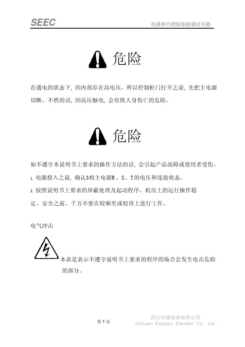
本表是表示不遵守说明书上要求的程序的场合会发生电击危险 的部分。
第1页
四川快速电梯有限公司 Sichuan Express Elevator Co., Ltd.
SEEC
电梯串行控制系统调试手册
序言
INTL’2000 电梯控制系统是我公司推出的智能化更高、功能更强、调试与维护更方 便的高技术产品。它除了具有一般电梯控制系统的基本功能外,在系统参数设置、电梯 功能选择、电梯调试与维护、现场适应能力等各方面有独到之处。
本系统的基本控制方式为串行通讯(CAN 总线)与变频调速;可满足电梯楼层 64 层以下,电梯速度小于 4 米/秒,包括永磁同步电机在内的各种电梯电机的控制要求。
INTL’2000 型电梯电脑控制器的主板、操纵盘板、呼梯板的核心芯片是国际著名工 业用单片机制造商 FUJITSU 的内部具有 32 位处理器的高端产品,集成度、可靠性堪称 世界一流;软件设计充分体现了功能齐备,参数设置界面层次分明,调试及故障诊断信 息充分,抗干扰能力强及干扰强度评价独具匠心的技术特点。对电梯控制系统以外的电 气元件设计了诊断与检测界面。使电梯故障判断有的放矢,真正使该电梯控制系统做到 了高性能与可靠性的完美统一,高水平与实用性的完美统一,高科技与应用简便的完美 统一。
1.2.3 防捣乱
当电梯运行至最远端楼层换速时,清除所有的内选登记。若电梯有负载检测装置,当轻载时, 内选最多可登记3个,多选无效。
1.2.4 呼梯按钮嵌入自诊断
若某一呼梯按钮按下时间超过 20s 而未断开,则系统认为该按钮嵌入。以后对该层呼梯不予登 记,且该按钮对应的呼梯应答不断闪烁报警。当该按钮断开时,退出上述状态。
SEEC
第一章
电梯串行控制系统调试手册
AO2000操作手册

内容:页数前言操作员手册和软件版本的联系安全须知电气测量设备安全利用技能第一章安装准备工作安装位置的选择采样气体入口和出口条件校验用测试气吹扫气电源交货范围安装需要的材料(不在交货范围)安装清单安装、启动方式第二章气体分析仪的拆箱及安装气体分析仪的拆箱气体分析仪的识别尺寸图气体连接口的安装气体分析仪的安装第三章气路连接分析仪模块连接图气体流路图壳体吹扫压力传感器气路连接吹扫气路的连接第四章电气连接电器模块的连接系统总线的连接Profibus总线单元、RS232/RS485通信单元接线图模拟输出单元接线图八通道模拟输出卡接线图模拟量输入/输出卡接线图离散量输入/输出单元接线图离散量输入/输出卡接线图标准功能块的连接信号、控制和接口线的连接电源线连接安全注意事项24V直流电源线连接115/230V交流电源线连接第五章分析仪系统的操作显示控制单元屏幕信息显示状态灯数字键盘取消键软键文字的输入数值的输入按键的输入密码保护用户接口优先级访问锁菜单栏第六章分析仪系统组态A 节气体组份测量功能量程变换更改量程范围Limas11、Uras14:更改量程范围改变小数点位数过滤器初始化自动量程初始化极限值监测器初始化激活组份选择更改模块名称B节功能模块功能块的概念标准组态功能块子菜单C节系统功能设按时区及时间、日期选择用户界面语言修改密码禁止操作安装系统模块添加系统模块修改系统模块删减系统模块保留组态信息配置状态信号配置互联网连接配置Modbus总线连接配置Profibus总线配置I/O总线D节显示显示的特点显示综述页面综述参数综述用户页面配置显示元素换页显示元素页内位置变换配置柱状图或点阵图输入数值输入数值的配置按键输入按键输入的配置第八章分析仪系统的校验A 节原理校验控制手动校验自动校验自动校验的测试气供给控制外部控制校验校验方式B节校验数据校验数据子菜单手动校验的校验数据自动校验的校验数据确认外部校验的校验数据当前输出响应C节校验分析仪单元注意事项Caldos15Caldos17Caldos17:校验气的单点校验Caldos15和Caldos17:替换气的校验Limas11Magnos106:Magnos106:单点校验Magnos106:替换气的校验Magnos17:Magnos17:替换气的校验Uras14:氧气检测器:D节校验分析仪模块手动校验手动启动自动校验第九章检查和保护检查检查气路密封性Caldos15和Magnos17:改换温度连接机构Uras14:光学对中Uras14:相位对中Limas11,Uras14:校验检测器的测量Limas11,Uras14:线性化Limas11:改换温度连接机构Limas11:铝化物采样检测器的清洁Limas11:石英采样检测器的清洁Limas11:安全采样器的清洁Limas11UV:指示灯的改换Limas11:放大器的优化气体模块:改换过滤器激活采样泵,采样泵输出的调整改变模拟输出电流的量程大气压力的修正大气压力值的修正校验的复位交叉敏感度载气第十章状态信息,故障修理处置状态系统状态:状态信息系统状态:状态信号状态信息的分类状态信息分析仪系统故障Caldos1五、Caldos17、Magnos10六、Magnos17故障Limas11故障Uras14故障气体模块故障通报服务附录1 气体分析仪概述气体分析仪分析仪模块带氧气探头的气体模块电气模块系统外壳显示控制单元附录二分析仪模块操作规范Caldos15操作规范Caldos17操作规范Limas11操作规范Magnos106操作规范Magnos17操作规范Uras14操作规范氧气操作规范电气安全前言操作手册内容:AO2000系列气体分析仪的安装、启动、操作和保护等信息,该手册包括了所有功能单元的内容,可能与交货的分析仪有不同。
阀门知识全面精讲(全套共609页)-第十六章——SHAFER LINEGUARD 2000 操作手册
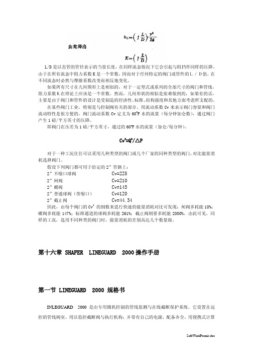
L/D是以直管的管径表示的当量长度,在同样流态情况下它会引起与阻挡件同样的压降。
由于在所有流态中阻力系数K是一个常数,因而对于任何特定的阀门或管件的L/D值,在不同流态时必然与摩擦系数改变而相反地变化。
如果所有尺寸在几何图形上是相似的,对于一定型式或系列的全部尺寸的阀门和管线,阻力系数K在理论上应该是一个常数。
然而,几何形状的相似是很难做到的,如果有的话,主要是由于阀门和管件的设计是受制造的经济性、标准、结构强度和其他方面考虑所支配的。
在某些阀门工业,特别是与控制阀有关的部分。
用流动系数Cv来表示阀门容量和阀门流动特性是很方便的。
阀门流动系数Cv定义为600F水的流量(每分钟加仑数),通过阀门产生1磅/平方英寸的压降。
即阀门在压差为1磅/平方英寸,通过的600F水的流量(加仑/每分钟)。
Cv2=Q2/△P对于一种工况往往可以采用几种类型的阀门或几个厂家的同种类型的阀门,对比能量消耗选择阀门。
假设下列阀门都可用于给定的2”管路上:2”不缩口球阀 Cv=2282”闸阀 Cv=2102”蝶阀 Cv=1452”普通球阀(带缩口) Cv=1202”截止阀 Cv=44.34因此,由每个阀门的Cv2 的倒数来进行快速的能量消耗对比可发现:闸阀多耗能18%;蝶阀多耗能147%;标准通道的球阀多耗能261%;截止阀则要多耗能2000%。
由此可见,同样的工况,选用不同种类的阀门时,能量消耗的差别高达几个数量级。
第十六章 SHAFER LINEGUARD 2000操作手册第一节 LINEGUARD 2000 规格书INLEGUARD 2000是由专用微机控制的管线监测与在线截断保护系统。
它设置在远控的管线阀室,用以监控截断阀与执行机构;并带有自己的电源、配备齐全。
用便携式计算机就地控制即可改变参数与下载时时数据。
LINGGUARD 2000控制器,具有远控通信能力,可对其实现完全远程操作控制。
这由一自备装置完成,它要求自己的电源并可做为无线电频率调制解调器,集输管线调制解调器,或能源线控制器。
OFS SC 连接器系列产品说明书

Applications• Local Exchange Carrier (LEC)• Competitive LEC (CLEC)•Broadband/Cable TV (CATV)A Furukawa CompanyFeatures• Field mountable connectors• Jumpers: simplex, duplex, quad, angled connectors, hybrids • Pigtails• Connectorized cables • Preterminated shelves• Terminated angled SC connectors • LIU and LGX ® panels • Simplex and duplex adapters • Attenuators•Tools and consumable kitsBenefits• Reduces assembly time and simplifies training• Easy-to-install adapters and connectors• Can be used in multiple applications including desk/workspace •Maintains optical contact under load, and helps prevent accidental disconnects • Helps minimize transmission problems•Optimizes optical contactProduct DescriptionOFS offers a complete family of fiber optic products featuring the SC Connector. With its familiar push-pull insertion release mechanism, the SC Connector is standard in most fiber applications and well known in the industry.A Furukawa CompanyMultimodeProduct Code (Comcode)3.0 mm P6200A-Z-126 (106917776)P6200A-Z-126-100 BULK(107503872)P6200A-Z-126-1000 BULK(300461803)1.6/2.0 mm P6200B2-Z-126 (300581576)P6200B2-Z-126-100 BULK(300537362)P6200B2-Z-126-1000 BULK(300537388)0.9 mmP6201A-Z-126 (106917800)P6201A-Z-126-100 BULK(107503880)P6201A-Z-126-1000 BULK(109161299)MultimodeProduct Code (Comcode)3.0 mm P6000A-Z-126 (106917438)P6000A-Z-126-100 BULK(107503856)P6000A-Z-126-1000 BULK(300464740)1.6/2.0 mm P6000B2-Z-126 (300581584)P6000B2-Z-126-100 BULK(300581592)P6000B2-Z-126-1000 BULK(300537396)0.9 mmP6001A-Z-125 (106917586)P6001A-Z-125-100 BULK(107503864)P6001A-Z-125-1000 BULK(300441128)3.0 mm 30 lbs, 20 lbsInsertion Loss µ,s 0.3 dB, 0.31.6/2.0 mm Fiber OD, nom 125 µm 0.9 mm2 lbs.Insertion Loss Stability< 0.3 dB Mount Time - Epoxy 8 min. avg.Mount Time - EZ 5 min. avg.Mating Durability< 0.2 dB Temperature Stability-40 ºC to 75 ºCSC ConnectorsThe SC Connector is an easily field mountable connector that is designedto mount on 900 micron buffered fiber, 1.6 mm jacketed cable and 3.0 mm jacketed cable. Jumper connector is also available with a reduced length cable support. It can be mounted on bare fiber but it is recommended that the fiber be buffered first using the D181755 kit or equivalent. The connector utilizes a zirconia ferrule for fiber alignment; and push-pull hardware for installation into the adapter. It can be used in high density applications and not be affected by axial cable loads. The cable is crimped to the outer hardware and therefore prevents momentary disconnect when axial load is placed on the cable. The 1032B5 Tool Kit contains all the tools and instructions needed to mount SC Connectors. The new MiniTool kit is available for mounting the connectors using the EZ method.Features• Snap-in connector design • Rugged and adaptablecompared to other connectors • Stable performance • Pull-proof design • TunableSC Single-Mode Connector (Simplex)SC Multimode Connector (Duplex)*SC Single-Mode Buffered Fiber ConnectorConnector (Simplex)SC MultimodeBuffered Fiber ConnectorSC Single-Mode Short-Boot Connector (Simplex)SC AdapterOFS offers SC Adapters in a varietyof configurations. The adapters are easily mounted by simply snapping them into a panel. The blue simplex adapter C6000A-4 can mate both multimode and single-mode connectors. The beige simplex multimode adapter uses a metallic sleeve and should only be used for multimode connectors. Single-mode adapters may be used for both single-mode and multimode connectors, while multimode adapters should only be used for multimode applications. OFS also offers angled adapters in a distinctive green color per industry standards.Note:Attenuators in both a build-on and UMA style are also available.SC Multimode Adapter (Duplex)SC Single-Mode Adapter (Simplex - front & rear)10SC1100A and 200A LIU Panel 6 Simplex 106 371 80010SC1-DPLX 100A and 200A LIU Panel 3 Duplex 107 025 *******SC1LGX, 200B, and 400A LIU 6 Simplex 106 372 121SC Multimode Ganged AdapterC6001A-5-100 C6001A-4-100, SC MM simplex adapter, 100 pack, short flange 300471331C6001A-RP-UA C6001A-RP-UA, SC MM 45° mount Angled Simplex Adapter300537990C6001A-RP-UA-100C6001A-RP-UA-100, SC MM 45° mount Angled Simplex Adapter, 100 pack 300538006C6061A-4 C6061A-4, SC MM duplex adapter107118903C6061A-4-100C6061A-4-100, SC MM duplex adapter, 100 pack 107504961C6061A-4-LS C6061A-4-LS, SC LaserWave ® Duplex Adapter108911728C6001A-5-LS C6001A-5-LS, SC LaserWave Simplex adapter, short flange300474368C6001A-RP-UA-LS C6001A-RP-UA-LS, SC Laserwave 45° mount Angled Simplex Adapter300538436C6001A-RP-UA-LS-100C6001A-RP-UA-LS-100, SC Laserwave 45° mount Angled Simplex Adapter, 100 pack 300538444C6070A-4C6070A-4, SC/ST MM duplex hybrid adapter 107087967C6000A-4C6000A-4, SC SM simplex adapter106703200C6000A-4-100C6000A-4-100, SC SM simplex adapter, 100 pack 300528668C6000A-5C6000A-5, SC SM Simplex, short flange107022980C6000A-5 -100C6000A-5-100, SC SM Simplex, short flange, 100 pack 107505042C6000A-5 -1000C6000A-5-1000, SC SM Simplex, short flange, 1000 pack 300471281C6000SC-RP C6000SC-RP, SC SM Simplex adapter, plastic latch108988817C6000SC-RP-100C6000SC-RP-100, SC SM Simplex adapter, plastic latch, 100 pack 108988825C6000A-RP-UA C6000A-RP-UA, SC SM 45° mount Angled Simplex Adapter300538014C6000A-RP-UA-100C6000A-RP-UA-100,SC SM 45° mount Angled Simplex Adapter, 100 pack 300538022C6060A-4C6060A-4, SC SM Duplex Adapter106817380C6060A-4-100 C6060A-4-100, SC SM Duplex Adapter, 100 pack 300485174C6060A-4-1000C6060A-4-1000, SC SM Duplex Adapter, 1000 pack109161307C6800A-4C6800A-4, SCAPC SM Simplex Adapter107562142C6800A-4-100C6800A-4-100, SCAPC SM Simplex Adapter, 100 pack108922766C6800A-4-1000C6800A-4-1000, SCAPC SM Simplex Adapter, 1000 pack300471299C6800A-RP-UA C6800A-RP-UA, SCAPC SM Unplated Angled Simplex Adapter300538030C6800A-RP-UA-100C6800A-RP-UA-100, SCAPC SM Unplated Angled Simplex Adapter, 100 pack300538048C6MMSC-10PK C6MMSC-10PK MM Adapter Strip 10 Pack108918442C6MMSC-20PK C6MMSC-20PK MM Adapter Strip 20 Pack300472768C6MMSC-LS-1C6MMSC-LS-1 LaserWave Adapter Strip Single Pack300395837C6MMSC-LS-10PK C6MMSC-LS-10PK LaserWave Adapter Strip 10 Pack108911413C6MMSC-LS-20PK C6MMSC-LS-20PK LaserWave Adapter Strip 20 Pack300472776 C6SMSC-1C6SMSC-1 SM Adapter Strip Single Pack300397866C6SMSC-10PK C6SMSC-10PK SM Adapter Strip 10 Pack108168782C6SMSC-Z-10PK C6SMSC-Z-10PK SM Zirconia Adapter Strip 10 Pack300472875C6SMSC-Z-20PK C6SMSC-Z-20PK SM Zirconia Adapter Strip 20 Pack300472883 C6APSC-1C6APSC-1 SMAPC Adapter Strip Single Pack108134982C6APSC-10PK C6APSC-10PK SMAPC Adapter Strip 10 Pack108168790C6APSC-Z-1C6APSC-Z-1 SMAPC Zirconia Adapter Strip Single Pack108134974SC ConverterThe SC-to-LC Converter features a male SC connector on thefront and an LC Adapter on the back. This converter can beused in those applications where customers may have chosen toconvert to the LC system (connectors and jumpers) but still hasan embedded base of SC adapters in their systems.The converter has been designed to yield an insertion loss of≤ 0.5 dB.SC TerminatorsThe SC Terminators from OFS are designed to reduce back-reflections typically found on laser-activated, connectorizedaccess points such as those on splitters, DWDM couplers, orLGX Fiber Distribution Frames. Any single fiber connector matedto an adapter or coupling that is unused is a source of back-reflection. Back-reflection can be a major cause of bit errors.OFS terminators are operational between 1310 and 1550 nm andprovide a reflectance of -45 dB.Terminator, SC-T107 796 686Terminator, SC-T-100107 860 157Converter, SC-LC109 119 834SC TerminatorSC Converter(front and back)duplex jumpers, the 2A1 clip is added in the factory to maintain the transmit/receive position of the simplex plugs. SC jumpers are available with reduced length cable supports for unique applications where space may be a constraint.The SC Jumpers are available in both 3.0 mm and 1.6 mm diameter cordage. The 1.6 mm cordage, allows greater jumper density in a fully loaded frame and prevents congestion in overhead racks or building risers. A duplex jumper made from a figure-eight MiniCord ® Cordage does not require a bulky bifurcation joint thereby saving space in the frame. The duplex MiniCord jumper can be peeled apart with ease so that two cords can be installed as one, then easily separated into two, saving time and effort. The single-mode cordage uses OFS’ AllWave ® FLEX Zero Water Peak (ZWP) Fiber providing excellent bend loss performance. The bend radius permits you to install jumpers or jumpers in spaces with limited maneuverability or around sharp corners. Quad jumpers utilize four color-coded 1.6 mm cords combined in one jacket.Jumpers are tested and must meet a maximum insertion loss of 0.3 dB. Field terminations using proper procedures should yield similar results. Jumpers come in fixed lengths or can be ordered in custom lengths. Hybrid jumpers are also available.Loss* : Avg./Std. Dev.0.15dB/0.08 dB (Tuned)†0.25 dB/0.12 dB0.2 dB/0.1 dBLoss* : Max0.3 dB 0.5 dB 0.5 dB Return Loss Minimum55 dB65 dB20 dBCable Retention: (1.6 mm), (3.0 mm)20 lbs./89.67 N, 30 lbs./133 N20 lbs./89.67 N, 30 lbs./133 N 20 lbs./89.67 N, 30lbs./133 NMating Durability, (500 Reconnects), Insertion loss change < 0.2 dB < 0.2 dB < 0.2 dB Temp. Stability (-40 °C to 75 °C), Insertion loss change< 0.3 dB< 0.3 dB< 0.3 dB* Complete connection concatenated statistics 8.8/125 fiber, dry connection.† Optical performance is dependant on ferrule end face cleanliness. Cleaning the end face prior to examination or installation is recommended. See Telcordia GR-326_COR, Issue 3, September 1999, Section 4.3 for recommended cleaning procedure.A Furukawa CompanyJR2WY002LCUSCU003M– Jumper Riser 2.0 mm AllWave FLEX Fiber Yellow 2 fibers (Zip) LCU SCU 003 Meters long JR9WY001LCUUNC003M– Jumper Riser 900 µm AllWave FLEX Fiber Yellow 1 fiber LCU UNC (Pigtail) 003 Meters longSMART Code syntax below has spaces between field sets for visibility. Actual SMART Code should not include any spacing.XXX X X XXX XXX XXX XXX XD-182720Consumables for mounting 100 SM Connectors using EZ107 834 0391510A Polishing Fixture - SC/ST108 237 7101510B Crimping Tool - SC/ST106 918 9981510LC Curing Fixture106 919 004Pad Universal Polishing Pad300 472 644MM Kit Universal Polishing Kit MM300 486 552SM Kit Universal Polishing Kit SM300 472 651Primer Primer106 730 849Adhesive Adhesive106 730 8561032H EZTermination Tool Kit640-252-044-UNIV Epoxy & EZ for ST/SC /pdfs/640-252-044-UNIV.pdf 640-252-049-03-UNIV Epoxy for SC MM & SM Using Universal Procedure /pdfs/640-252-049-03-UNIV.pdf 640-252-049-02-UNIV EZ for SC MM & SM using Universal Procedure /pdfs/640-252-049-02-UNIV.pdf 640-252-044-06-UNIV Epoxy for ST II MM & SM using Universal Procedure /pdfs/640-252-044-06-UNIV.pdf 640-252-053-UNIV BTW LC Universal Procedure /pdfs/640-252-053-UNIV.pdf 640-252-054-UNIV LC Jumper Connector Universal Polishing Procedure /pdfs/640-252-054-UNIV.pdf D-182804Consumables for mounting 100 MM Connectors using EZ108 919 143A Furukawa CompanyFor additional information please contact your sales representative.You can also visit our website at or call 1-888-fiberhelp (1-888-342-3743) USA or 1-770-798-5555 outside the USA.Copyright © 2017 OFS Fitel, LLC. All rights reserved, printed in USA. OFS Marketing Communications DOC: fap-119 Date: 07/17A Furukawa CompanyAllWave, Blue Tiger, EZ Bend, LaserWave, LGX and MiniCord are all registered trademarks of OFSFitel, LLC.OFS reserves the right to make changes to the prices and product(s) described in this documentat any time without notice. This document is for informational purposes only and is not intended to。
J-2000 SC 木材含水量表操作手册说明书

J-2000/SC WOOD MOISTURE METER OPERATION MANUALSCANDINAVIAN MODEL VS 1.5DELMHORST EUROPETITANIUMLAAN 100NL 5221 CK ‘s-HERTOGENBOSCHTHE NETHERLANDS*****************+31 (0)73 6395080TABLE OF CONTENTSJ-2000 Features 2Before You Begin 3Button Functions 3Check Calibration 3Set Species 4Species Code Chart 5Set Temperature 6Set Temperature Mode 6Taking a Reading 7Information About Your Readings 7To Check Accumulated Readings 8To Reset the Meter 8Care of Your Meter 9Service For Your Meter 9Warranty 10This product is covered by EU directive 2002/96/EC (WEEE). For disposal please contactyour supplier or local authorities for instructions as to best do so.J-2000 FEATURESResistance technology recognized world wide as the most accurate method for measuring moisture6% - 40% moisture rangeDigital readoutAverages up to 100 accumulated readingsBuilt-in correction for 50 different speciesBuilt-in temperature compensation both Fahrenheit and CelsiusProven microcontroller circuit for increased reliability and accuracyEasy one-hand operationIncludes (1) 9-Volt BatteryIncludes a sturdy carrying caseOne year warrantyFor 60 years of proven quality, accuracy and serviceBUTTON FUNCTIONS- Reads the Percent Moisture Content value (%MC), corrected for temperature and species.(#2) Calibration Check Button - Checks meter calibration. It also displays the average of up to 100 accumulated readings; displays the maximum stored reading;erases the readings.(#3) Species Button - Sets the species code for the wood you are using.(#3) Species button. The species are numbered from 1 to 50 and are listed on the Species Code Chart. This button also acts as a scroll key, depending on the function.(#4) Temperature Button -Sets the wood temperature. This button also acts as a scroll key, depending on the function.Press the calibration check button #2 and read button #1 simultaneously. Meter is in calibration if it displays 22% (+ or - .2).If you check the calibration and the meter does not display 22% it is likely an indication of a low battery. If this occurs, change the battery immediately. Continued use with a low battery may cause the meter to go out of calibration. If you have a fresh battery and the instrument still does not indicate a proper calibration, return it to DELMHORST for service. See “Service for Your Meter” section.When the battery is removed and then reconnected, the meter displays its software version for one second and then turns itself off. After replacing the battery, you must reset the meter as described in “Resetting the Meter” section. We recommend to NOT use rechargeable batteries.SET SPECIESThe J-2000 /SC defaults to Species Code # 1 – Scandinavian Pine. Because the electrical characteristics of different species vary, all species read differently at the same moisture content. For this reason you need to adjust for species. If you are working with a species other than Douglas Fir, set the species code using the species button (#3), and the meter will make the necessary corrections.To change species press the species button (#3). The meter will display the current species code for one second.To scroll forward through the species list hold the species button (#3)while the current species code is displayed and scroll to the species number desired.To scroll backward through the species list, press and release the species button (#3). Within one second, press and hold the temperature button (#4). Continue to hold the temperature button (#4) and the species number will decrease.When scrolling in either direction, release the button to stop at your desired species.The J-2000 can be used to test more than just wood. It will also give a relative reading on plywood, OSB, particleboard and MDF or can be fitted with a 26-ES slide hammer for specific applications. Call Delmhorst Europe at +31 736395080 or send an e-mail to ***************** for information on how to interpret the readings for other materials.SPECIES CODE CHART Code Species Code Species1 Scandinavian Pine 26 Keruing2 Scandinavian Spruce 27 Larch3 Scandinavian Birch 28 Magnolia4 Fir, Douglas 29 Mahogany, African (also Khaya)5 Pine, Southern 30 Mahogany, Honduras6 SPF 31 Mahogany, Philippine7 Alder 32 Maple, Hard/Soft8 Apitong 33 Meranti, Dark Red9 Aspen 34 Oak, Red10 Ash, White 35 Oak, White11 Basswood 36 Pecan12 Birch, Merbau 37 Pine, Longleaf13 Cedar, Eastern Red 38 Pine, Ponderosa14 Cedar, Incense 39 Pine, Shortleaf15 Cherry 40 Pine, Sugar16 Cottonwood 41 Pine, White17 Cypress, Sapupira 42 Poplar, Yellow18 Elm, American 43 Ramin19 Fir, Red 44 Radiata Pine20 Fir, White 45 Redwood21 Gum, Black 46 Spruce, Sitka22 Gum, Red 47 SPF, COFI*23 Hemlock, Western 48 Teak24 Hackberry 49 Virola25 Hickory 50 Walnut, BlackSET TEMPERATUREThe J-2000 defaults to a temperature of 20ºC. As wood temperature increases, its electrical resistance decreases and indicated moisture content rises. Lower wood temperatures result in lower indicated moisture content. A correction is necessary if the wood temperature is outside the range of 10ºC to32ºC. Set the temperature accordingly and the meter will make the correction.To change temperature press and release the temperature button (#4). The meter will display the current temperature for one second.To scroll forward through the temperature settings, press and hold the temperature button (#4) while the current temperature is displayed.To scroll backward press and release the temperature button (#4). Within one second, press and hold the species button (#3). Continue to hold the species button (#3) and the temperature will decrease.When scrolling in either direction, release the button to stop at the desired temperature.SET TEMPERATURE MODEThe meter will display the current temperature setting and will wait one more second until shutting off so that you may change the temperature value as described above.In Celsius, the temperature will change in increments of either 2°C or 3°C.In the Celsius mode, positive values will display in whole numbers; negative values will display with a decimal point and a “-“ sign in the left-hand corner. (i.e.: -17.0)TAKING A READINGThe contact pins provided are best for stock up to 6/4. On stock over 6/4 or for hardwoods over 4/4 we recommend using a remote probe such as the 26-ES ram-type electrode. Mount the 26-ES directly to the external connector. See additional information under the “Pin Talk” section.Remove the protective cover to expose the pins. Check that the contact pins are firmly hand tightened.To take a reading, align the contact pins parallel to the grain and push them to their full penetration into the wood, if possible. Insulated pins read only at the tip and can be driven to the desired depth. Press the read button (#1) and read the moisture content on the meter scale. The meter displays the %MC for two seconds.To add a reading to the sum of all the previously stored readings, release the read button (#1) within 2 seconds.INFORMATION ABOUT YOUR READINGSReadings below 6% will be displayed as a numeric value, (-##.#), and will not be added to accumulation. A reading below 6% which is due to temperature and species adjustments will be shownas a numeric value with no minus sign and this reading will be added to the accumulation.The meter will overrange at “40” The overrange indication is a blinking (40). Readings above 40% arenot added to the accumulationThe meter will accumulate up to 100 readings. After all 100 readings are stored it will not add new readings until the memory has been cleared. It will also continue to display the average of all 100 readings as a reminder that the memory is full.When taking and storing readings for a specific wood species, be sure to “clear” the meter before moving on to the next species if you do not want to group all of the readings together.TO CHECK ACCUMULATED READINGSThis feature allows you to view the total number of all accumulated readings, the average of those readings, and the highest stored reading.•To view the readings press and release the calibration check button (#2). First the meter displays the number of accumulated readings for one second, then the average of those readings for two seconds. Then it displays the highest stored reading for two seconds. The total “cycle” time is five seconds.•To erase readings hold the calibration check button (#2) down for 5 seconds. All accumulated readings will be erased and the meter will display “0”.TO RESET METERPress and release the calibration check button (#2).Within one second press the species button (#3).The meter will reset itself and display in order “120" = #1 (Scandinavian Pine), “10” (model ID), “1.5” (Firmware Version 1.5) and “22” (±0.2 Calibration Check)CARE OF YOUR METERTo keep your meter in good working order:Store your meter in a clean, dry place. The protective carrying case provided is an ideal storage place when themeter is not in use.Change the 9-Volt battery as needed. Continued use with a low battery may cause the meter to go out of calibration.Change contact pins as needed. Keep pin retainers hand tightened.Clean the meter, contact pins, and probes with any biodegradable cleaner.Use the cleaner sparingly and on external parts only. Keep the cleaner out of the external connector. DO NOT IMMERSE THE METER OR ANY ELECTRODE IN WATER.Remove the battery if the meter will not be used for one month or longer.SERVICE FOR YOUR METERPack your meter securely. Enclose a purchase order or letter with a brief description of the problem. There is no need to call us for a return authorization number if you are within the EU. Customers outside the EU must contact us for more specific instructions prior to returning a meter.Include your name, address, daytime phone and fax numbers or e-mail address. If you believe the meter is under warranty, please provide the original sales slip or invoice.Ship via UPS, Express Mail, Priority Mail or any overnight courier who provides prompt service. Do not use standard parcel post.Insure your instrument for its full value and ship prepaid. We are not responsible for damage in transit.We do not accept COD shipments or cover any incoming freight or duty charges on returned merchandiseTurnaround time on repairs is approximately two weeks.We will call you with an estimate if you specifically request one, or if we determine that the meter may be too costly to repair.Non-warranty repairs will be returned via UPS/COD unless you have already established other payment terms. There is no COD service outside the EU.Payments have to be made by Bank transfer prior to the return shipment. A proforma invoice will be raised in advance.Warranty repairs will be returned at no charge if shipped within the EU via UPS Ground Service.Freight charges for expedited services (i.e., Federal Express, UPS/2 Day, UPS/1 Day, etc.) are the customer’s responsibility and will be charged as per the above terms.WARRANTYDELMHORST EUROPE, referred to hereafter as DELMHORST, guarantees your moisture meter for oneyear from date of purchase and any optional electrodes against defects in material or workmanship for 90 days. If, within the warranty period of themeter, you find any defect in material or workmanship return the meter following the instructions in the “Service for Your Meter” section. This limited warranty does not cover abuse, alteration, misuse, damage during shipment, improper service, unauthorized or unreasonable use of the meter or electrodes. This warranty does not cover batteries, pin assemblies, or pins. If the meter or any optional electrodes have been tampered with, the warranty shall be void. At our option we may replace or repair the meter. DELMHORST shall not be liable for incidental or consequential damages for the breach of any express or implied warranty with respect to this product or its calibration. With proper care and maintenance the meter should stay in calibration; follow the instructions in the “Care of Your Meter” section.Under no circumstances shall DELMHORST be liable for any incidental, indirect, special, or consequential damages of any type whatsoever, including, but not limited to, lost profits or downtime arising out of or related in any respect to the meters or electrodes and no other warranty, written, oral or implied applies. DELMHORST shall in no event be liable for any breach of warranty or defect in this product that exceeds the amount of purchase of this product. The express warranty set forth above constitutes the entire warranty with respect to Delmhorst meters and electrodes and no other warranty, written, oral, or implied applies. This warranty is personal to the customer purchasing the product and is not transferable.DELMHORST EUROPETitaniumlaan 1005221 CK ‘s-HertogenboschThe Netherlands*****************For already 65 years, Delmhorst is a leading brand for high-quality resistance moisture meters. Today the Delmhorst range consists of a complete line of portable moisture meters for a variety of different applications including woodworking / lumber, agriculture, construction and paper.。
顶康农业美国DIGI-STAR Scale Link 2000 ISO系列操作手册说明书
DIGI-STARScale Link 2000 ISO SeriesOperator’s ManualTopcon Agriculture Americas, LLCW5527 Hwy 106Fort Atkinson, WI 53538USATel: 800-225-7695E-mail:*******************D4196-EN Scale Link 2000 ISO Operator’s Manual LA CAll rights reserved. Reproduction of any part of this manual in any form whatsoever without Topcon Agriculture Americas express written permission is forbidden. The contents of this manual are subject to change without notice. All efforts have been made to assure the accuracy of the contents of this manual. However, should any errors be detected, Topcon Agriculture Americas would greatly appreciate being informed of these errors. The above notwithstanding, Topcon Agriculture Americas can assume no responsibility for errors© Copyright! 2017 Topcon Agriculture Americas, Fort Atkinson (U.S.A.).IntroductionTable of Contents1.0 INTRODUCTION (4)1.1 Additional Documents (4)2.0 TECHNICAL SPECIFICATIONS (5)3.0 SAFETY DURING USE (6)3.1 Exposure to Radio Frequency (6)3.2 Prior to Operation (6)3.3 Check System Before Use (6)3.4 Cleaning (6)3.5 Battery Charging and Welding (6)4.0 KEYS USED ON SCALE LINK ISO TERMINAL (7)5.0 SCALE LINK CONTROL OVERVIEW (8)6.0 OVERVIEW SCALE LINK ISOBUS SYSTEM (10)7.0 SETUP SCREENS FOR EACH SCALE DISPLAYED (11)7.1 Scale Setup Screen Overview (12)7.2 Scale Select (13)7.3 Enter Scale ID (13)7.4 Select Unit of Measure (14)7.5 Select Weigh Method (14)7.6 Enter/View Setup Number (15)7.7 Enter/View Calibration Number (15)7.8 Select Display Count (16)8.0 SYSTEM SETUP SCREEN OVERVIEW (17)8.1 Sum Weight Mode (18)8.2 Direct Access Numbers (18)9.0 OPERATION (20)9.1 Preset (20)9.2 Configure Main Screen Layout (23)9.3 Tare and Net/Gross (24)9.4 Using the M+, CM, RM, and Weight Averaging Functions (25)9.5 Troubleshooting Load Cells (26)10.0 OPTIONS CHANGED BY USER (27)10.1 Direct Access Numbers (D.A.N.) (27)1.0 INTRODUCTIONThank you for your purchase of a Scale Link model SL2110, SL2140, SL2210, SL2220, or SL2240 ISO system. (The abbreviation SL2 will used in places in this manual.)Your Scale Link ISO system is the culmination of more than 30 years of agricultural weighing engineering and expertise. With proper operation and preventive maintenance, the Scale Link will last for many years.The Scale Link ISO connects to an ISO Bus backbone and a UT (Universal Terminal) can communicate with the Scale Link ISO.Use of the Scale Link ISO system outside of its intended purposes may result in damage to instrument.1.1 Additional DocumentsAdditional Document information listed below;D4197- SL2 Operation ManualD4020- Direct Access Numbers (D. A. N.)D3986- ERM Operators ManualAdditional Documents for setup and troubleshooting;D4000- Digi-Star ISOBUS / CAN Application NotesD4204- SL2 Technical Manual2.0 TECHNICAL SPECIFICATIONSVOLTAGE RANGE 11V – 36V DC (12V & 24V machinery) with reverse polarityprotection.*Limited to 11- 16V with SLC2810 or ISOBUScompliant implements.*************** OPTIONS <200mA base scale with 4 load cells to 5.0A maximum with all options. Internal self-resetting fuses for PCB protection & SLC remote protection.LOAD CELL PLATFORMS 16 Maximum 350 ohm transducers; 1 platform x 16 bars, 2 x 8,or 4 x 4.LOAD CELL EXCITATION Regulated 8.0VDC, current sensing and overcurrent protected. OPERATINGENVIRONMENT-29℃ to 60℃ (-20℉ to 140℉); 0 to 95% RH non-condensing. ENCLOSURE IP65 per IEC529REMOTE INPUT Active high or active low base on software setting; 0 –10,000Hz.OUTPUT CONTROL/ALARM Active high 3.0A continuous, with 5.0A surge.SERIAL PORT RS232 Com 1 & Com 2; 1200 – 115K baud; 7/8 bits; E/O/Nparity; Scoreboard/ streaming data; Serial Gross Weight; DSERM compatible.INTERNAL USB PORT USB 2.0 A port; FAT32; up to 4G. For settings Save/ Load,Software Update; ISOBUS update.SCALE LINK CONTROL SPI bus on 8 pin M12 supports SLC2810, SLC2400,custom SPI remotes.CAN 1 PORT General purpose CAN port; ISOBUS and Universal Terminal(UT) Compatible Typically connects with DT6, DT4, and otherstandard Connector types.CAN 2 PORT Proprietary CAN port for connection to other devices orsensors.Technical SpecificationsSafety During Use3.0 SAFETY DURING USEDanger: Indicates an imminently hazardous situation that, if not avoided, WILL result in death or very serious injury.Warning: Indicates a potential hazardous situation that, if not avoided, CAN result in death or very serious injury.Caution: Indicates a potential hazardous situation that, if not avoided, MAY result in a minor injury.IMPORTANT !: Signals special mechanical information3.1 Exposure to Radio FrequencyExposure to energy from radio frequencies is an important safety issue. As this product uses the Wi-Fi and Cellular system of a smartphone or tables please consult with the safety information provided with the device that the App operates with.3.2 Prior to OperationRead and understand this manual and learn all controls before you use the equipment.Check that the area is clear of people, animals, and obstacles before starting any work.Identify possible hazards.3.3 Check System Before UseIMPORTANT ! Before using the App with the Digi-Star weighing system read the Operator’s Manual for the scale indicator and the Wi-Fi system. Follow all instructions.3.4 CleaningDo not use pressurized running water (high pressure cleaners, hoses nozzles, etc.) to clean the indicator. Water ingress and damage to the indicator may result. Use soapy water and a sponge or cloth for best results.3.5 Battery Charging and WeldingDisconnect all cables from the ScaleLink2 system before charging the battery or welding on the machine. If cables are left connected, damage to the Scale Link and/or Load Cells may result.4.0 KEYS USED ON SCALE LINK ISO TERMINAL NOTE: Not all keys are shown on every screen--HOME:--ENTER SETUP SCREENS:--CLEAR MEMORY:--CONFIGURE MAIN SCREEN LAYOUT: --HOLD:--CANCEL:--TARE:--NET/GROSS:--ZERO:--PRESET:--ADD TO MEMORY:--SAVE TO USB:--LOAD FROM USB:--MOVE TO RIGHT:--MOVE TO LEFT:--ENTER:--MOVE UP:--MOVE DOWN:--RECALL MEMORY:--TO ENTER DIRECTACCESS NUMBERS: Keys Used on Terminal5.0 SCALE LINK CONTROL OVERVIEW- Pause - Cancel- Enter setup screens - Temporary zero (Net Mode)- Toggles between Net and Gross Weights- Press and hold for 3 seconds to zero balance indicator.- Enter preset weight- Add to memory1234567812345678910111213141516SL2 Control OverviewSummed Weight – Total weight of scale A+B+C+DScale A – Gross WeightScale B – Gross WeightScale C – Gross WeightScale D – Gross WeightMask Number – Mask version that is applied to screenSoftware Version – Displays current software versionHardware Detected – Displays which hardware is recognized by the SL2910111213141516Scale Link2 Control OverviewOverview Scale Link ISOBUS System 6.0 OVERVIEW SCALE LINK ISOBUS SYSTEMThe Scale Link is part of a weighing system. The Scale Link 2000 powers the Load Cells from one to 4 scale bins, hoppers, or platforms and monitors and filters the weight output signals which is converted into a weight. The weight information is sent via ISOBUS to the Universal Terminal.The ISOBUS Universal Terminal (UT) provides the interface to the Scale Link through a Scale Link mask that is brought up on the UT. This interface mask on the UT displays the weight of material in the chosen bin, hopper, or platform, and provides a means to change the selected bin, hopper, or platform, and to Tare the weight (set a temporary zero) to allow precise loading or unloading.In addition, the Scale Link interface mask provides the means for the operator to view, control, change settings, and to perform basic diagnostics of the scale system.Setup Screens7.0 SETUP SCREENS FOR EACH SCALE DISPLAYEDThis display shows the four scales,initially labelled: A, B, C, and D. Eachscale can have customized settings.The size and position of individual scaleinformation can be changed.Different scale names, setups (weightunits, count size, etc.) and calibrationsare possible.In the four-scale setup shown at left, thescale that is selected is shown with agreen background (Scale D) with largerview at the top of the display.7.1 Scale Setup Screen OverviewSelect Scale – Touch White box used to select scale.Scale ID – ID or name of selected scale. Example Tank 1, Bin 2, or AMS 3.Units – Select unit for weight to be measured in. Example LBS, KG.Weigh Method – Sensitivity as to how weight numbers move. General (default), Slow and Fast.Setup Number – View or edit Setup Number. The Setup Number is a quick-entry method to change multiple settings in one location. Includes: WeighMethod, Gain, Count Size, & CapacityCalibration Number – View or edit Calibration Number. Sets the Calibration of the scale.Adjusted to make the scale system more accurate.Display Counts – In the example above the system is set to 10 pounds. Weight will change bymultiples of 10, as in 10, 20, 30, 40, etc.Motion -Instructions on how to operate or modify these functions is shown in the following pages.12345677.2 Scale Select7.3 Enter Scale ID 1. Touch white box next to SelectScale and a drop down box will bedisplayed.2. Select scale “A” through “D”.3. Press green box to save setting.Press red box to cancel selection.1. Touch white box next to Sale IDand a drop-down box will bedisplayed.2. Using key pad enter desired scaleID or name.Example; TANK1, RIGHT, LEFTREAR.3. Press green button to savesetting. Press red button to cancelsetting.1212337.4 Select Unit of Measure7.5 Select Weigh Method 1. Press white box to select unit tobe used from drop down box.2. Press green to save setting.Press red box to cancel setting.1. Press white box to select weighmethod. Select General (default),Slow and Fast weighing (determineshow fast weight numbers changethat are displayed).Weigh Method is related tosensitivity. Switching to Fast willmake the scale more sensitive tochanges in weight. However, thismay result in a system that is toosensitive and the weight displayedwill easily be changed by movementor wind.2. Press green to save setting. Pressred to cancel setting.1212Setup Screens7.6 Enter/View Setup NumberThe Scale Link utilizes a shorthand “S etup” number that determines how the scale displays the weight .7.7 Enter/View Calibration NumberThe Scale Link utilizes a “Calibratio n” number for each scale system that matches the load cells to the Scale Link and determines the weight value that is displayed.1. Touch white box next to SetupNumber and a drop down box will be displayed.2. Using key pad, edit or viewsetup number.3. Press green button to save.Press red button to cancel.1. Touch white box next toCalibration Number and a drop down box will be displayed.2. Using key pad, edit or viewcalibration number.3. Press green button to save.Press red button to cancel.123123Setup Screens7.8 Selec t Display CountCounts are the increments in which the scale system will display changes in weight. For example; 0, 10, 20, 30, and so on.1. Touch white box next to DisplayCount and a dropdown box will be displayed.2. Select display count desired.3. Press green button to save.Press red button to cancel.Utilizing too small of a Count size will result in what appears to be an unstable weight as the weight will constantly change between two counts. Increase the Count until a stable number is displayed.1238.0 SYSTEM SETUP SCREEN OVERVIEWWt (Weight) Broadcast Interval – How often the scale sends a weight reading.Preferred Address – System will auto detect this address once connected to SL2.Preferred UT Number – System will auto detect this number once connected to SL2.Sum Weight Mode – Choose from Single, Total, or Combined.Sum Weight BAM – Sum weight is sent to specific equipment (for OEM’s). Serial Gross BAM – Serial weight is sent to specific equipment (for OEM’s). Direct Access Number – Access and Edit D.A.N Numbers.1234567123458.1 Sum Weight ModeSingle Scale Mode : Each scale will act independently. Each scale has its own weight and all operations apply to the currently selected scale.Total Scales Mode : The weight of all scales is summed together and displayed as a single weight. However, operations (ie. Tare, Zero, & Net/Gross) are only applied to the currently selected scale. Combined Scales Mode : The weight of multiple scales is summed together and displayed as a single weight. Operations (ie. Tare, Zero, & Net/Gross) are applied to all scales.8.2 Direct Access NumbersDirect Access Numbers (DAN) are used to change specific settings in the Scale Link. Changes to DAN settings should not be made without training or knowledge the system.1. Touch white box next to SumWeight Mode and a drop down box will be displayed.2. Select mode desired.3. Press green button to save.Press red button to cancel.1231. Touch grey box labelled DirectAccess Numbers.12. Touch white button and enterapplicable D.A.N Number.29.0 OPERATION 9.1 Preset4 3. Adjust options corresponding tothe D.A.N. number that wasentered.4. Use the Enter Setup Screensbutton to return to HomeScreen.3System Setup Screen Overview1. Touch Preset button in lowerright of screen.12. Touch white box under PresetValue and enter desired presetvalue.23. Press green button to savevalue. Press red button tocancel.34. Touch Run Preset.5. Begin unloading or loading.46. Screen will correspond with7unloading or loading process.7. Touch enter to print screen,Touch Cancel to return toHome.69.2 Configure Main Screen Layout1. Touch Configure Main ScreenButton.12. Screen will show 8 windows toconfigure options for each ofthe available 4 scales.(Net/Gross can be shown foreach of the 4 scales if needed.)9.3 Tare and Net/Gross3. Use the drop down menus toconfigure the main screen asdesired.1. When the selected scale displaysthe desired weight touch Tare. Atemporary “NET” Zero (0) weightwill be displayed.2. Add more weight. The weight ofthis additional weight will bedisplayed.3. To know the original weight, plusthe added weight, touchNet/Gross to show the total“GROSS” w eight.4. To toggle back to NET weightpress Net/Gross13Operation9.4 Using the M+, CM, RM, and Weight Averaging FunctionsThese functions can be used to save, add, recall, and clear stored values in the same way as when using an electronic calculator.1. Add Weight to selected scale.1Then press M+. This will addthis weight to the indicatormemory and return to theGROSS weighing mode.2. The RM (Recall Memory) andWeight Averaging features canbe accessed through the mainscreen layout. See section 9.2to configure main screen layout.29.5 Troubleshooting Load Cells3. Use the CM button to ClearMemory.31. Follow steps in section 8.2 toarrive at screen to enter directaccess numbers.2. Enter D.A.N. code 1997.3. Press up arrow and then enterto access information about theload cells.233Operation10.0 OPTIONS CHANGED BY USERFollow instructions as noted in Section 8.2 above. Direct Access Numbers (DAN) are used to change specific settings in the Scale Link. Changes to DAN settings should not be made without training or knowledge the system. It is recommended that before changing DAN settings that the original setting(s) be written down in case it is necessary to revert back.10.1 Direct Access Numbers (D.A.N.)SETTING [display] D.A.NNO.OPTIONS [displayed]DESCRIPTIONISOBUSISOBUSWEIGHT(ISO WT)2701 Select rate to broadcast ISOBUS weight data.ISOBUS BASE ADDRESS (ISOADR) 2702Assign starting base the ISOBUS gateway shouldaddress claim.USE ISOBUS DDI VALUES (ISODDI) 2704If ON –Send ISO WT using ISOBUS DDI’s 229 & 232.OFF –Use D/S legacy DDI’sISOBUS VTINSTANCENUMBER(ISOINT)2705 Preferred virtual terminal instance to display mask on.CAN MESSAGETYPE(CANMSG)2711 Allows for entry of a proprietary can message type.CAN MESSAGE INTERVAL (CANINT) 2712Allows for editing of the interval time for the CANMSGoutput.MOTION & WEIGHTA,B,C,DDISPLAY FORMAT (ABCDSP) 3091Select the single (A, B, C, D), Total (A+B+C+D), orCombined (1 scale, 2-4 inputs) for ABCD scales.ANALOG LOWWEIGHT(LOW WT)3201 Enter analog weight value to equal 4mA or 0 volts.ANALOG HIGHWEIGHT)3202 Enter analog weight value to equal 20mA or 5 volts.ANALOGSELECT(ANAOUT)3203 Select 0-5V or 0-20mA output.NEGATIVEANALOG OUTPUT (-ANALG) 3204Allow 4-20mA to output weight values less than Analoglow weight.ANALOG OUTPUT TEST (ANTEST) 3209 Select output for testing. Normal, Min, Max, or SawOptions Changed By User[display] NO.DESCRIPTIONCOMMUNICATION PORT MAPPINGOPSTAT PORT (OPSTAT) 5007 OFF, COM1, COM2, orCOM3Set opstat portDDL PORT (DDLPRT) 5009 OFF, COM1, COM2, orCOM3Sets DDL port.20MA MIRROR PORT(20MAMR) 5011 OFF, COM1, COM2, orCOM3Sets port for 20MA signal to mirror.RECIPE PORT (RECPRT) 5012 OFF, COM1, COM2, orCOM3Sets recipe output port.GPS PORT (GPSPRT) 5013 OFF, COM1, COM2,COM3, or COM4Sets GPS output port.CAN PORT(CANPSPRT)5111 Used to send a specific message via the CAN bus.DEBUG PORT (DBGPRT) 5999 OFF, COM1, COM2, orCOM3Sets internal debug port.SCALE SPECIFIC SETTINGS - SCALE PLATFORM ASCALE IDSETUP(SCALID)7101 Identity of scale location.WEIGH METHOD (WMTHD) 71031-General2-Slow3-Fast4-LockSelect weigh method.DISPLAY UNIT (LB-KG) 7104lb-poundsKg-KilogramsDisplay pounds or kilogramsCAPACITY(CAP)7106 Enter MAXIMUM weight measureable on scale.WM1 ADJUST 1(WMA1-1)7107 2-100 Increase this number to smooth the weighing.WM1 ADJUST 2(WMA1-2)7108 0 = off Use value less than WMA1-1 for quick weight response. WM1 ADJUST 3(WMA1-3)7109 Enter the weight to activate quick weight response.WM2 ADJUST 1(WMA2-1)7111 Increase this number to smooth the weighing.WM2 ADJUST 2(WMA2-2)7112 0 = off Use value less than WMA2-1 for quick weight response. WM2 ADJUST 3(WMA2-3)7113 Enter the weight to activate quick weight response. MOTION(MOTION)7114 If ON – motion arrow flashes for unstable weightMOTION WEIGHT (MOT WT) 7115Enter weight used to detect Motion. 0 = StandardMotion DetectionTARE AUTOPRINT(TAREAP)7116 If ON – tare will auto print displayed weight.SAVE TARE 7117 If ON – Indicator will save tare weight to non-volatileOptions Changed By User[display] NO.DESCRIPTION (SAVTAR) memory.SCALE PLATFORM BSCALE IDSETUP(SCALID)7151 Identity of scale location.WEIGH METHOD (WMTHD) 71531-General2-Slow3-Fast4-LockSelect weigh method.DISPLAY UNIT (LB-KG) 7154lb-poundsKg-KilogramsDisplay pounds or kilogramsCAPACITY(CAP)7156 Enter MAXIMUM weight measureable on scale.WM1 ADJUST 1(WMA1-1)7157 2-100 Increase this number to smooth the weighing.WM1 ADJUST 2(WMA1-2)7158 0 = off Use value less than WMA1-1 for quick weight response. WM1 ADJUST 3(WMA1-3)7159 Enter the weight to activate quick weight response.WM2 ADJUST 1(WMA2-1)7161 Increase this number to smooth the weighing.WM2 ADJUST 2(WMA2-2)7162 0 = off Use value less than WMA2-1 for quick weight response. WM2 ADJUST 3(WMA2-3)7163 Enter the weight to activate quick weight response. MOTION(MOTION)7164 If ON – motion arrow flashes for unstable weightMOTION WEIGHT (MOT WT) 7165Enter weight used to detect Motion. 0 = StandardMotion DetectionTARE AUTOPRINT(TAREAP)7166 If ON – tare will auto print displayed weight.SAVE TARE (SAVTAR) 7167If ON – Indicator will save tare weight to non-volatilememory.SCALE PLATFORM CSCALE IDSETUP(SCALID)7201 Identity of scale location.WEIGH METHOD (WMTHD) 72031-General2-Slow3-Fast4-LockSelect weigh method.DISPLAY UNIT (LB-KG) 7204lb-poundsKg-KilogramsDisplay pounds or kilogramsCAPACITY(CAP)7206 Enter MAXIMUM weight measureable on scale.WM1 ADJUST 1 7207 2-100 Increase this number to smooth the weighing.Options Changed By UserSETTING [display] D.A.NNO.OPTIONS [displayed]DESCRIPTION(WMA1-1)WM1 ADJUST 2(WMA1-2)7208 0 = off Use value less than WMA1-1 for quick weight response. WM1 ADJUST 3(WMA1-3)7209 Enter the weight to activate quick weight response.WM2 ADJUST 1(WMA2-1)7211 Increase this number to smooth the weighing.WM2 ADJUST 2(WMA2-2)7212 0 = off Use value less than WMA2-1 for quick weight response. WM2 ADJUST 3(WMA2-3)7213 Enter the weight to activate quick weight response. MOTION(MOTION)7214 If ON – motion arrow flashes for unstable weightMOTION WEIGHT (MOT WT) 7215Enter weight used to detect Motion. 0 = StandardMotion DetectionTARE AUTOPRINT(TAREAP)7216 If ON – tare will auto print displayed weight.SAVE TARE (SAVTAR) 7217If ON – Indicator will save tare weight to non-volatilememory.SCALE PLATFORM DSCALE IDSETUP(SCALID)7251 Identity of scale location.WEIGH METHOD (WMTHD) 72531-General2-Slow3-Fast4-LockSelect weigh method.DISPLAY UNIT (LB-KG) 7254lb-poundsKg-KilogramsDisplay pounds or kilogramsCAPACITY(CAP)7256 Enter MAXIMUM weight measureable on scale.WM1 ADJUST 1(WMA1-1)7257 2-100 Increase this number to smooth the weighing.WM1 ADJUST 2(WMA1-2)7258 0 = off Use value less than WMA1-1 for quick weight response. WM1 ADJUST 3(WMA1-3)7259 Enter the weight to activate quick weight response.WM2 ADJUST 1(WMA2-1)7261 Increase this number to smooth the weighing.WM2 ADJUST 2(WMA2-2)7262 0 = off Use value less than WMA2-1 for quick weight response. WM2 ADJUST 3(WMA2-3)7263 Enter the weight to activate quick weight response. MOTION(MOTION)7264 If ON – motion arrow flashes for unstable weightMOTION WEIGHT 7265Enter weight used to detect Motion. 0 = StandardMotion DetectionOptions Changed By UserSETTING [display] D.A.NNO.OPTIONS [displayed]DESCRIPTION(MOT WT)TARE AUTOPRINT(TAREAP)7266 If ON – tare will auto print displayed weight.SAVE TARE (SAVTAR) 7267If ON – Indicator will save tare weight to non-volatilememory.SETUP & CALIBRATIONDEAD WEIGHTCALIBRATION(CAL8121 Calibration method using weights.TEMPCALIBRATION(TCALB)8123 If ON – Scale adjusts for temperature changes.CALIBRATIONMATCH(CALMAT8124 Calibration method used for matching a known weight.SYSTEM DATE FORMAT (SYSDTF) 8719Allows date format to be changed when printing storedrecords.CALIBRATION MATCH (CALMAT) 8724Allows adjustment to the calibration number bu inputtingtwo weight values.LOAD DISPLAY POOL(L POOL) 8732Load a display pool from the USB device into internalmemory.DISPLAY POOLSTATUS(D POOL)8733 Show/Display pool status in internal memoryISOBUS VTENABLE(ISO VT)8745 Enable/Disable uploading mask (pool) data up to a VTSCALE PLATFORM ASETUP NUMBER (SETUP) 8771Quick entry value to select weigh method, gain, displaycounts and capacity.CALIBRATIONNUMBER(CAL)8781 Weight displayed at 0.4mV/V for these load cells.SCALE PLATFORM BSETUP NUMBER (SETUP) 8772Quick entry value to select weigh method, gain, displaycounts and capacity.CALIBRATIONNUMBER(CAL)8782 Weight displayed at 0.4mV/V for these load cells.SCALE PLATFORM CSETUP NUMBER (SETUP) 8773Quick entry value to select weigh method, gain, displaycounts and capacity.Options Changed By UserSETTING [display] D.A.NNO.OPTIONS [displayed]DESCRIPTIONCALIBRATIONNUMBER(CAL)8783 Weight displayed at 0.4mV/V for these load cells.SCALE PLATFORM DSETUP NUMBER (SETUP) 8774Quick entry value to select weigh method, gain, displaycounts and capacity.CALIBRATIONNUMBER(CAL)8784 Weight displayed at 0.4mV/V for these load cells.MISCELLANEOUS UTILITESKEYTEST 8888 Enables front panel key testCLOCK 8997 Enables clock – press any key to return to weighing modeOptions Changed By User。
- 1、下载文档前请自行甄别文档内容的完整性,平台不提供额外的编辑、内容补充、找答案等附加服务。
- 2、"仅部分预览"的文档,不可在线预览部分如存在完整性等问题,可反馈申请退款(可完整预览的文档不适用该条件!)。
- 3、如文档侵犯您的权益,请联系客服反馈,我们会尽快为您处理(人工客服工作时间:9:00-18:30)。
紫光扫描仪型号:L A2000
Windows
Phot
o Express
TWAIN
TWAIN
TWAIN
TWAIN
TWAIN
TWAIN
24-bit
JPEG2000
(dpi
)
TWAIN
Prescan
Pr
TWAIN Prescan Preview
Preview
48-Bit
24-Bit
CMYK
256 Color
256 Gray 256
Gray (16 bit)
65536
Text / Line Art
300
dpi
TWAIN
30
使用扫描仪软件面板
请点击“开始”菜单程序列表中的Panel V2.0
( )启动程序,如下步骤:
1、点击开始 所有程序 Uniscan LA2000 Panel V2.0
>>
>2、电脑屏幕上会出现“Uniscan LA2000 - Panel V2.0”
工作窗口。
扫描 编辑 复印 文字识别 退出
导入 PDF 电子邮件 设置扫描仪软件面板设置
点选一下软件面板上的设置键会出现设置
画面,您可以更改软件面板中的各项按键
的设置。
扫描按键
欲完成转化为PDF格式的档案,请按下列方
式操作:
1、将您要转化为PDF的文件或图像正面朝下
轻贴在扫描仪的玻璃面板上。
2、按PDF键,扫描仪会先进行扫描,同时屏
幕上会出现工作进度显示,告诉您目前的扫
描工作完成进度。
当扫描结束后,屏幕上会
出现一个“继续添加”选择窗口,选择“否
”,系统会自动将图像转化为PDF文件格式。
注意:如果选择“是”,则会再一次扫描。
欲使用扫描键扫描文件,请按下列方式操作:
1、将要扫描的文件或图像正面朝下轻贴在扫描
仪的玻璃面板上。
2、按扫描仪上的扫描键开始扫描,扫描时屏幕
上会出现工作进度显示,告诉您目前扫描工作
完成进度。
当扫描结束后,扫描的图像会显示在
“Uniscan LA2000 - Panel V2.0”预览窗口。
复印按键
欲使用复印键复印文件,请按下列方式操作
1、将您要复印的文件或图像正面朝下轻贴在扫描
仪的玻璃面板上。
2、按复印键,扫描仪会先进行扫描,同时屏幕上
会出现工作进度显示,告诉您目前的扫描工作完成
进度。
当扫描结束后,屏幕上会出现一个“打印”
窗口。
3、您可以在您的电脑上自行调整复印数量(打印
输出)后点击电脑屏幕上的打印。
4、操作完成后,系统会将文件送至打印机打印输
出。
PDF按键
电子邮件按键
欲使用电子邮件键发送电子邮件,请按下列
方式操作:
1、将您要扫描的文件或图像正面朝下轻贴在
扫描仪的玻璃面板上。
2、按电子邮件键,扫描仪会先进行扫描,同
时屏幕上会出现工作进度显示,告诉您目前
的扫描工作完成进度。
当扫描结束后,系统
会自动开启您在扫描仪按键设置(硬件设置)
软件面板按键
按软件面板按键,电脑屏幕上会出现“Uniscan
LA2000 - P anel V2.0”窗口。
更多关于“Uniscan LA2000 - Panel V2.0”软件面板窗口
的操作,请参照help辅助说明。
中选择的电子邮件软件,并将扫描后的JPEG
图片以附件的方式传送。
扫描仪按键设置
请点击“开始”菜单程序列表中的扫描仪按键设置( )启动程序(如下列步骤):
1、点击开始 所有程序 Uniscan LA2000
扫描仪按键设置(硬件设置)
>>
>
2、电脑屏幕上会出现“Uniscan LA2000 - 扫描仪按键设置”设置画面,您可以更改扫描、电子邮件
、复印和PDF各按键的设置。