1MBI400NB-120中文资料
IGBT的型号,参数,及价格总结

43
CT 15SM-24
15A/1200V IGBT单管
CT 35SM-8
200A/400V IGBT单管
41
CT 75AM-12
75A/600V IGBT单管
78
三菱型号(1U 600V) IGBT
技术指标
批价(元)
三菱型号(1U 600V) IGBT
技术指标
批价(元)
400A/1200V/1U
1150
1MBI 200F-120
200A/1200V/1U
655
1MBI 400NN-120
400A/1200V/1U
1150
1MBI 300F-120
300A/1200V/1U
880
1MBI 400L(N)(S)-120
400A/1200V/1U
1150
1MBI 300L(N)(S)-120
200A/1200V/2U
930/1030
CM 150E3Y(E3U)-24E
150A/1400V/2U
880/960
CM 300DY(DU)-24(E)
300A/1200V/2U
1630/1580
CM 200E3Y(E3U)-24E
200A/1400V/2U
1080/1210
CM 50DY-28H
300A/600V/2U
780/880
CM 300E3Y(E3U)-12E
300A/600V/2U
960/1080
CM 400DY(DU)-12H(E)
400A/600V/2U
1455
型号2U
(1200/1400V) IGBT
1MBI400S-120(IGBT管)
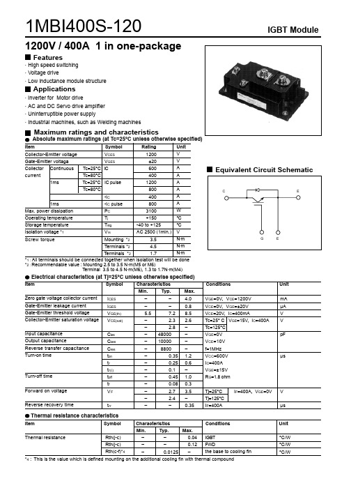
1MBI400S-120IGBT Module1200V / 400A 1 in one-packageFeatures· High speed switching · Voltage drive· Low inductance module structureApplications· Inverter for Motor drive· AC and DC Servo drive amplifier · Uninterruptible power supply· Industrial machines, such as Welding machinesMaximum ratings and characteristicsThermal resistance characteristicsThermal resistance ––0.04––0.12–0.0125 –IGBT FWD the base to cooling fin °C/W°C/W °C/W *4 : This is the value which is defined mounting on the additional cooling fin with thermal compoundItem Symbol Characteristics Conditions Unit Min. Typ. Max.Rth(j-c)Rth(j-c)Rth(c-f)*4Characteristics0123452004006008001000Collector current vs. Collector-Emiiter voltageTj= 25°C (typ.)C o l l e c t o r c u r r e n t : I c [ A ]Collector - Emitter voltage : VCE [ V ]0123452004006008001000Collector current vs. Collector-Emiiter voltageTj= 125°C (typ.)Collector - Emitter voltage : VCE [ V ]C o l l e c t o r c u r r e n t : I c [ A ]0123452004006008001000Collector current vs. Collector-Emiiter voltageVGE=15V (typ.)Collector - Emitter voltage : VCE [ V ]C o l l e c t o r c u r r e n t : I c [ A ]510152025246810Collector-Emiiter voltage vs. Gate-Emitter voltageTj= 25°C (typ.)C o l l e c t o r - E m i t t e r v o l t a g e : V C E [ V ]Gate - Emitter voltage : VGE [ V ]051015202530351000500010000100000Capacitance vs. Collector-Emiiter voltage (typ.)VGE=0V, f= 1MHz, Tj= 25°CC a p a c i t a n c e : C i e s , C o e s , C r e s [ p F]Collector - Emitter voltage : VCE [ V ]010002000300040002004006008001000Dynamic Gate charge (typ.)Vcc=600V, Ic=400A, Tj= 25°CGate charge : Qg [ nC ]C o l l e c t o r - E m i t t e r v o l t a g e : V C E [ V]0510152025G a t e - E m i t t e r v o l t a g e : V G E [ V ]0100200300400500600700501005001000Switching time vs. Collector current (typ.)Vcc=600V, VGE=+-15V, Rg= 1.8ohm, Tj= 25°CS w i t c h i n g t i m e : t o n , t r , t o f f , t f [ n s e c ]Collector current : Ic [ A ]0100200300400500600700501005001000Switching time vs. Collector current (typ.)Vcc=600V, VGE=+-15V, Rg= 1.8ohm, Tj= 125°CCollector current : Ic [ A ]S w i t c h i n g t i m e : t o n , t r , t o f f , t f [ n s e c ]0.5110505010050010005000Switching time vs. Gate resistance (typ.)Vcc=600V, Ic=400A, VGE=+-15V, Tj= 25°CGate resistance : Rg [ ohm ]S w i t c h i n g t i m e : t o n , t r , t o f f , t f [ n s e c ]020040060080020406080100Switching loss vs. Collector current (typ.)Vcc=600V, VGE=+-15V, Rg=1.8ohmS w i t c h i n g l o s s : E o n , E o f f , E r r [ m J /p u l s e ]Collector current : Ic [ A ]0.5110500100200300Switching loss vs. Gate resistance (typ.)Vcc=600V, Ic=400A, VGE=+-15V, Tj= 125°CS w i t c h i n g l o s s : E o n , E o f f , E r r [ m J /p u ls e ]Gate resistance : Rg [ ohm ]2004006008001000120014000100200300400500600700800900 Reverse bias safe operating area+VGE=15V, -VGE<=15V, Rg>=1.8ohm, Tj<=125°CCollector - Emitter voltage : VCE [ V ]C o l l e c t o r c u r r e n t : I c [ A ]Outline Drawings, mmmass : 380g200400600800Forward current vs. Forward on voltage (typ.)F o r w a r d c u r r e n t : I F [ A ]Reverse recovery characteristics (typ.)Vcc=600V, VGE=+-15V, Rg=1.8ohm1E-30.010.050.10.5T h e r m a l r e s i s t a n s e : R t h (j -c ) [ °C /W ]Pulse width : Pw [ sec ]。
富士FUJI 标准IGBT(1MBI、2MBI、6MBI),智能IPM(6MBP、7MBP、7MBR)
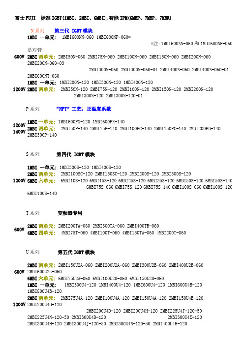
富士FUJI 标准IGBT(1MBI、2MBI、6MBI),智能IPM(6MBP、7MBP、7MBR) N系列第三代 IGBT模块600V 1MBI 一单元: 1MBI600NN-060 1MBI600NP-060**注:1MBI600NN-060和1MBI600NP-060是对管2MBI两单元: 2MBI50N-060 2MBI75N-060 2MBI100N-060 2MBI150N-060 2MBI200N-0602MBI200N-060-032MBI300N-060 2MBI300N-060-04 2MBI400N-060 2MBI400N-060-01 2MBI600NT-0601200V 1MBI 一单元: 1MBI200N-120 1MBI300N-120 1MBI400N-1202MBI两单元: 2MBI50N-120 2MBI75N-120 2MBI100N-120 2MBI150N-120 2MBI200N-120 2MBI300N-120 2MBI300N-120-01P系列“NPT”工艺,正温度系数1200V 1400V 1MBI一单元: 1MBI600PX-120 1MBI600PX-1402MBI两单元: 2MBI50P-140 2MBI75P-140 2MBI100PC-140 2MBI150PC-140 2MBI200PB-140 2MBI300P-140S系列第四代 IGBT模块1200V 1MBI 一单元: 1MBI300S-120 1MBI400S-1202MBI两单元: 2MBI100SC-120 2MBI150SC-120 2MBI200S-120 2MBI300S-1206MBI六单元: 6MBI10S-120 6MBI15S-120 6MBI25S-120 6MBI35S-120 6MBI50S-120 6MBI50S-140 6MBI75S-060 6MBI75S-120 6MBI75S-140 6MBI100S-060 6MBI100S-1206MBI100S-140T系列变频器专用600V 2MBI两单元: 2MBI200TA-060 2MBI300TA-060 2MBI400TB-0604MBI四单元: 4MBI75T-060 4MBI100T-060 4MBI150TA-060 4MBI200T-060U系列第五代IGBT模块600V 2MBI两单元: 2MBI150U2A-060 2MBI200U2A-060 2MBI300U2B-060 2MBI400U2B-060 2MBI600U2E-0606MBI六单元: 6MBI75U2A-060 6MBI100U2B-060 6MBI150U2B-0601200V 1MBI 一单元: 1MBI300U4-120 1MBI400U4-120 1MBI600U4-120 1MBI600U4B-120 1MBI800U4B-120 2MBI两单元: 2MBI75U4A-120 2MBI100U4A-120 2MBI150U4A-120 2MBI150U4B-120 2MBI200U4B-120 2MBI200U4D-120 2MBI200U4H-120 2MBI225U4J-120-50 2MBI225U4N-120-502MBI300U4D-120 2MBI300U4E-120 2MBI300U4H-120 2MBI300U4J-120-502MBI300U4N-120-50 2MBI400U4H-1202MBI450U4E-120 2MBI450U4J-120-50 2MBI450U4N-120-506MBI六单元: 6MBI35U4A-120 6MBI50U4A-120 6MBI75U4A-120 6MBI75U4B-1206MBI75UC-120 6MBI100U4B-120 6MBI100UC-120 6MBI150U4B-120 6MBI225U4-120 6MBI300U4-1206MBI450U4-1201700V 2MBI两单元: 2MBI100U4H-170 2MBI150U4H-170 2MBI200U4H-170 2MBI300U4H-1702MBI400U4H-1706MBI六单元: 6MBI75U4B-170 6MBI100U4B-170 6MBI150U4B-170 6MBI225U4-170 6MBI300U4-170 6MBI450U4-170大电流等级1200V1MBI 一单元: 1MBI1200U4C-120 1MBI1600U4C-120 1MBI2400U4D-120 1MBI3600U4D-120 2MBI两单元: 2MBI600U4G-120 2MBI800U4G-120 2MBI1200U4G-1201700V1MBI 一单元: 1MBI1200U4C-170 1MBI1600U4C-170 1MBI2400U4D-170 1MBI3600U4D-170 2MBI两单元: 2MBI600U4G-170 2MBI800U4G-170 2MBI1200U4G-170智能IGBT模块(IPM)一、工业级IPM:适用于变频空调,伺服控制等,内设欠压、过热、过流保护功能,开关频率最大20kHZ600V电压6MBP六单元:6MBP15RH060 6MBP20RH060 6MBP30RH060二、R系列IPM:(适用于通用变频器等,内设欠压、过热、过流保护功能)600V 电压6MBP六单元:6MBP20RTA060 6MBP50RA060 6MBP75RA060 6MBP100RA060 6MBP150RA060 6MBP200RA060 6MBP300RA060 6MBP50RTB060 6MBP50RTJ060 6MBP75RTB0606MBP75RTJ060 6MBP100RTB060 6MBP100RTJ060 6MBP150RTB060 6MBP150RTJ060 7MBP 七单元:7MBP50RA060 7MBP75RA060 7MBP100RA060 7MBP150RA060 7MBP200RA060 7MBP300RA060 7MBP50RTB060 7MBP50RTJ060 7MBP75RTB060 7MBP75RTJ0607MBP100RTB060 7MBP100RTJ060 7MBP150RTB060 7MBP150RTJ0601200V 电压6MBP六单元: 6MBP15RA120 6MBP25RA120 6MBP50RA120 6MBP50RJ120 6MBP75RA120 6MBP75RJ120 6MBP100RA120 6MBP150RA1207MBP 七单元:7MBP25RA120 7MBP25RJ120 7MBP50RA120 7MBP50RJ1207MBP75RA120 7MBP75RJ120 7MBP100RA120 7MBP150RA120PIM(智能功率集成模块)含整流桥七单元600V电压7MBR20SC060 7MBR30SA060 7MBR30SC060 7MBR50SA060 7MBR50SB060 7MBR50SC060 7MBR75SB060 7MBR75SD060 7MBR100SB060 7MBR100SD0601200V电压7MBR10SA120 7MBR10SC120 7MBR15SA120 7MBR15SC120 7MBR25SA120 7MBR25SC120 7MBR35SB120 7MBR35SD120 7MBR50SB120 7MBR50SD1201400V电压7MBR10SA140 7MBR15SA140 7MBR25SA140 7MBR35SB140 7MBR50SB140。
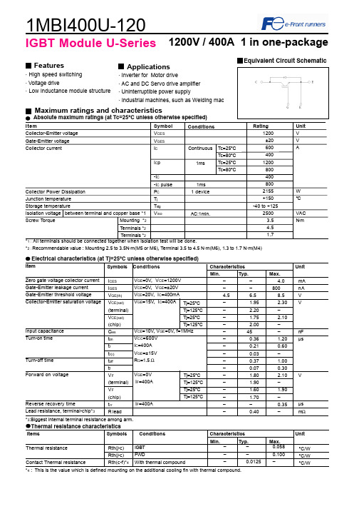
1MBI400U-120资料
VGE=0V IF=400A
IF=400A
Tj=25°C Tj=125°C Tj=25°C Tj=125°C
Min. – – 4.5 – – – – – – – – – – – – – – – –
Typ. – – 6.5 1.95 2.20 1.75 2.00
45 0.36 0.21 0.03 0.37 0.07 1.80 1.90 1.60 1.70 – 0.40
Input capacitance Turn-on time
Turn-off time Forward on voltage
Reverse recovery time Lead resistance, terminal-chip*3
ICES IGES VGE(th) VCE(sat) (terminal) VCE(sat) (chip) Cies ton tr tr(i) toff tf VF (terminal) VF (chip) trr R lead
Ic=200A
0
5
10
15
20
25
Gate - Emitter voltage : VGE [ V ]
Dynamic Gate charge (typ.) Vcc=600V, Ic=400A, Tj= 25°C
VGE
Collector current : Ic [A]
Collector-Emitter voltage : VCE [ 200V/div ] Gate - Emitter voltage : VGE [ 5V/div ]
12V
600
10V 400
200
0 0
8V
1
2
3
2MBI150U4A-120中文资料

Range of frequency : 10 ~ 500Hz Sweeping time : 15 min. Acceleration : 100m/s2 Sweeping direction : Each X,Y,Z axis Test time : 6 hr. (2hr./direction) Maximum acceleration : 5000m/s2 Pulse width : 1.0msec. Direction : Each X,Y,Z axis Test time : 3 times/direction Storage temp. : 125±5 ℃ Test duration : 1000hr. Storage temp. : -40±5 ℃ Test duration : 1000hr. Storage temp. : 85±2 ℃ Relative humidity : 85±5% Test duration : 1000hr. Test temp. : 120±2 ℃ Test humidity : 85±5% Test duration : 96hr. Test temp. : Low temp. -40±5 ℃ High temp. 125 ±5 ℃ RT 5 ~ 35 ℃ : High ~ RT ~ Low ~ RT 1hr. 0.5hr. 1hr. 0.5hr. : 100 cycles : High temp. 100
Feb.-09 -’05
Enactment
T.Miyasaka K.Yamada
Y.Seki
MS5F6031
2 13
H04-004-06b
元器件交易网
2MBI150U4A-120
1. Outline Drawing ( Unit : mm )
IGBT模块系列

型号(1U 1400V/1700V) IGBT CM 400HA-28H CM 600HA-28H CM 1000HA-28H CM 400HA-34H 型号(2U 600V) IGBT
技术指标 400A/1400V/1U 600A/1400V/1U 1000A/1400V/1U 400A/1700V/1U 技术指标 50A/600V/2U 75A/600V/2U 100A/600V/2U 150A/600V/2U 200A/600V/2U 300A/600V/2U 400A/600V/2U 技术指标 50A/1200V/2U 75A/1200V/2U 100A/1200V/2U 150A/1200V/2U 200A/1200V/2U 300A/1200V/2U 50A/1400V/2U 75A/1400V/2U 200A/1400V/2U
CM 50E3Y(E3U)-12E CM 75E3Y(E3U)-12E CM 100E3Y(E3U)-12E CM 150E3Y(E3U)-12E CM 200E3Y(E3U)-12E CM 300E3Y(E3U)-12E
技术指标 300A/1400V/2U 50A/1400V/2U 75A/1400V/2U 100A/1400V/2U 150A/1400V/2U 200A/1400V/2U 300A/1400V/2U 400A/2500V/2U 400A/3300V/2U
批价(元)型号(2U 600V) 223 268 313 475 637 637 680
2MBI 50L(F)(N)-060 2MBI 75L(F)(N)-060 2MBI 100L(F)(N)-060 2MBI 150L(F)(N)-060 2MBI 150LB(KB)-060 2MBI 150NK(NC)-060 2MBI 200L(F)(N)-060
BS EN 120 中文
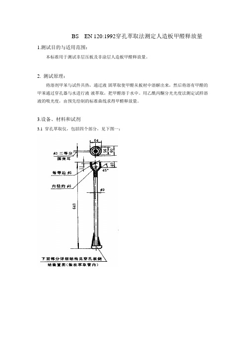
BS EN 120:1992穿孔萃取法测定人造板甲醛释放量1.测试目的与适用范围:本标准用于测试非层压板及非涂层人造板甲醛释放量。
2. 测试原理:将溶剂甲苯与试件共热,通过液-固萃取使甲醛从板材中溶解出来,然后将溶有甲醛的甲苯通过穿孔器与水进行液-液萃取,把甲醛溶于水中。
用乙酰丙酮分光光度法测定试样溶液的吸光度,由预先绘制的标准曲线求得甲醛释放量。
3.设备、材料和试剂3.1 穿孔萃取仪,包括四个部分,见下图一:萃取管穿孔器中穿孔板烧结装置穿孔萃取装置图一测定甲醛释放量的穿孔萃取仪部件图3.1.1 标准磨口圆底烧瓶,1000 mL,用以加热试件与溶剂进行液一固萃取;3.1.2 萃取管,具有边管(包以石棉绳)与小虹吸管,中间放置穿孔器进行液一液穿孔萃取;3.1.3 冷凝管,通过一个大小接头与萃取管联结,可促成甲醛一甲苯气体冷却液化与回流;3.1.4 液封装置,防止甲醛气体逸出的虹吸装置,包括90°弯头,小直管防虹吸球与三角烧瓶3.2 恒温加热套,宜于加热1000 mL 圆底烧瓶,功率300 W,可调温度范围50~20 0℃。
3.3 分析天平3.4 鼓风干燥箱,能保持(103 ± 2)℃3.5 恒温水浴锅3.6 可见分光光度计。
3.7 玻璃器皿滴定管:50 mL;碘量瓶:500 mL;烧杯:100 mL,250 mL,500 mL,1000 mL;容量瓶:1000 mL,100 mL,2000 mL;棕色容量瓶:1000 mL;移液管:2.0 mL,5 mL,25 mL,50 mL,100 mL;50 mL 具塞比色管;玻璃研钵,直径10 ~12 cm。
3.8 小口塑料瓶,500 mL 与1000 mL。
3.9 试剂甲苯(C7H8),分析纯碘化钾( KI ),分析纯;重铬酸钾(K2Cr2O7),优级纯;硫代硫酸钠(Na2S2O3·5H2O),分析纯;碘化汞(Hgl2),分析纯;无水碳酸钠(Na2CO3),分析纯;硫酸(H2SO4),ρ=1.84g/mL,分析纯;盐酸(HCl),ρ=1.19g/mL,分析纯;氢氧化钠(NaOH),分析纯;碘(I2),分析纯;可溶性淀粉,分析纯;乙酰丙酮(CH3COCH3COCH3) ,优级纯;乙酸铵(CH3COONH4),优级纯;甲醛溶液(CH20),浓度35%-40%。
压电材料与应用

迄今为止,可被考虑的无铅压电陶瓷体系有: 1.BaTiO3基无铅压电陶瓷 a(1-x) BaTiO3-xABO3(A=Ba、Ca等,B=Zr、Sn、Hf、Ce等) I II I II b (1-x) BaTiO3-xA B O3 (A =K、Na,B =Nb、Ta) c(1-x) BaTiO3-xAII0.5NbO3 (AII=Ca、Sr、Ba)
材料 Kp Kt d33 (PC/N)
g33 (×10-3Vm/N)
F15-6 15PZTPZT-4 F15-7 15F C-1 P-5 PS PZTPZT-8 F3 SW2 SW3 PGB PZTPZT-7 F 2-6 BTBT-2
0.62 0.58 0.52 0.57 0.58 0.55 0.59 0.59 0.51 0.56 0.32
压电材料性能指标 压电材料性能指标
Kt Kp
K33 K15 K31
3、机械品质因数Qm
压电材料性能指标 压电材料性能指标
压电陶瓷在振动时,为了克服内摩擦需要消耗能量。 压电陶瓷在振动时,为了克服内摩擦需要消耗能量。机械品质因数Qm 是反映能量消耗大小的一个参数。 越大,能量消耗越小。 是反映能量消耗大小的一个参数。Qm越大,能量消耗越小。机械品质因数 的定义式是: Qm的定义式是:
压电材料概述
压电陶瓷
优点:抗酸碱,机电耦合系数高,易制程任意形状,价格 优点:抗酸碱,机电耦合系数高,易制程任意形状, 便宜。 便宜。 缺点:温度系数大,需高压极化处理(kV/mm) (kV/mm)。 缺点:温度系数大,需高压极化处理(kV/mm)。
压电聚合物
优点:低声学阻抗特性,柔软可做极薄的组件。 优点:低声学阻抗特性,柔软可做极薄的组件。 缺点:压电参数小,需极高的极化电场(MV/mm) 缺点:压电参数小,需极高的极化电场(MV/mm)
2MBI200U4B-120中文资料

Contact Thermal resistance Rth(c-f) with Thermal Compound 0.025 (1 device) (*4) (*4) This is the value which is defined mounting on the additional cooling fin with thermal compound.
(Aug.-2001 edition)
Mechanical Tests
Test Method 401 MethodⅠ Test Method 402 methodⅡ Test Method 403 Reference 1 Condition code B
3 Vibration
4 Shock
1 High Temperature Storage 2 Low Temperature Storage 3 Temperature Humidity Storage 4 Unsaturated Pressurized Vapor
C/W
6. Indication on module Logo of production
2MBI200U4B-120
200A 1200V
Lot.No. 7. Applicable category
Place of manufacturing (code)
This specification is applied to IGBT-Module named 2MBI200U4B-120.
MS5F6032
5 13
H04-004-03a
元器件交易网
11. Reliability test results
Reliability Test Items
2MBI100N-120中文资料
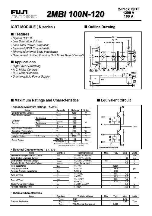
• Absolute Maximum Ratings ( Tc=25°C)
Items
Symbols
Ratings Units
Collector-Emitter Voltage Gate -Emitter Voltage
VCES VGES
1200
V
± 20
V
Collector Current
Max. Power Dissipation Operating Temperature Storage Temperature
Items
Symbols
Zero Gate Voltage Collector Current
ICES
Gate-Emitter Leackage Current
IGES
Gate-Emitter Threshold Voltage
VGE(th)
Collector-Emitter Saturation Voltage
Continuous 1ms Continuous 1ms
IC IC PULSE -IC -IC PULSE PC Tj Tstg
100
200
A
100
200
780
W
+150
°C
-40 ∼ +125 °C
Isolation Voltage Screw Torque
A.C. 1min.
Vis
2500
V
Mounting *1
trr
Test Conditions VGE=0V VCE=1200V VCE=0V VGE=± 20V VGE=20V IC=100mA VGE=15V IC=100A VGE=0V VCE=10V f=1MHz VCC=600V IC=100A VGE=± 15V RG=9.1Ω IF=100A VGE=0V IF=100A
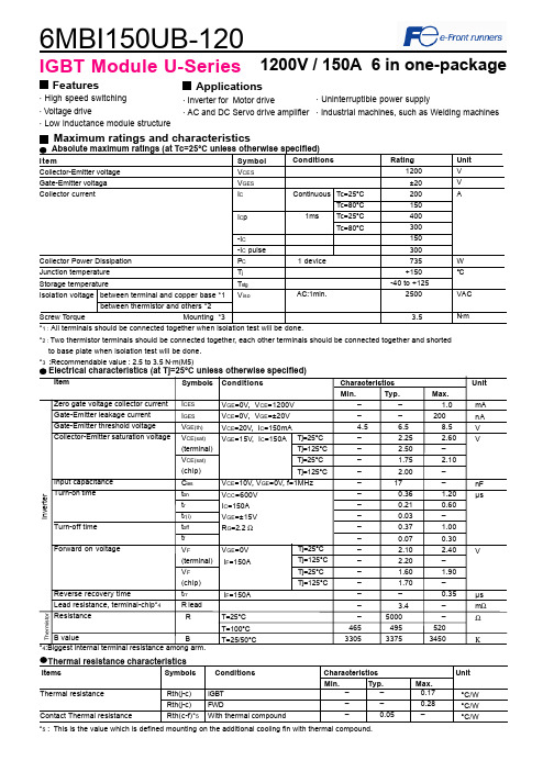
6MBI150UB-120中文资料
tr 100
tf
10 0.1
1.0
10.0
100.0
Gate resistance : Rg [ Ω ]
1000.0
Switching loss vs. Gate resistance (typ.) Vcc=600V, Ic=150A, VGE=±15V, Tj= 125°C 125
Eon 100
Items
Symbols
Conditions
Thermal resistance Contact Thermal resistance
Rth(j-c) Rth(j-c) Rth(c-f)*5
IGBT FWD With thermal compound
Characteristics
Min. –
Typ. –
tr
tr
100
100
tf
tf
10 0
50
100
150
200 250
300
Collector current : Ic [ A ]
10000
Switching time vs. Gate resistance (typ.) Vcc=600V, Ic=150A, VGE=±15V, Tj= 25°C
ton toff
Screw Torque
Mounting *3
-IC -IC pulse PC Tj Tstg Viso
Conditions
Continuous Tc=25°C Tc=80°C
1ms Tc=25°C Tc=80°C
1 device
AC:1min.
Rating 1200 ±20 200 150 400 300 150 300 735 +150
211274579_BS-400全自动分枝杆菌液体培养系统对分枝杆菌培养的效果评价
基金项目!浙江省医药卫生科技计划项目#-)-4T5(+F$ 作者单位!浙江大学医学院附属杭州市胸科医院临床检验实验 中心&杭州4()))X 通信作者蔡龙 ! &=>?'@!J?'@&1P4(<!L&C>?'@/J&>
Copyright©博看网. All Rights Reserved.
系统对疑似结核病患者临床标本中分枝杆菌的检测效能较高&具有较好的应用价值(
关键词分枝杆菌属%感染%培养技术%评价研究
中图分类号E4<,*+(
;6*-2*"(/%/0"'$$00$)"/0T!1O@@72"/5*"()M.)/,*)"$#(25U(V2(4G2-"2#$!.3"$5/% M.)/,*)"$#(25)2-"2#$ %'. %$(*("(*&)#( 1#2.(*&C,#(* Z'.:,#"&!">#$&!">'#(8'&M,$'\"(8#(*&+#"!$(*0 +7"(":#7!#P$3#4$38 +.(4.3&>#(*R,$'O,$3#:":>$-2"4#7B55"7"#4.94$M,.="#(*U("Q.3-"48C:,$$7$5;.9":"(.&>#(*R,$'GDEEEN&+,"(# +$33.-2$(9"(*#'4,$3!+#"!$(*&H/#"7!:#"7$(*GDF,$4/#"70:$/
NBB-400中文资料

RF Micro Devices, Inc.
Tel (336) 664 1233
7628 Thorndike Road
Fax (336) 664 0454
Greensboro, NC 27409, USA
4-33
元器件交易网
NBB-400
• Linear and Saturated Amplifiers
• Gain Stage or Driver Amplifiers for MWRadio/Optical Designs (PTP/PMP/ LMDS/UNII/VSAT/WLAN/Cellular/DWDM)
Product Description
δGT/δT
MTTF versus Temperature @ ICC=50mA
Case Temperature Junction Temperature MTTF
Thermal Resistance
θJC
Specification
Min.
Typ.
Max.
15.5
16.7
16.5
16.0
12.5
13.5
The NBB-400 cascadable broadband InGaP/GaAs MMIC amplifier is a low-cost, high-performance solution for general purpose RF and microwave amplification needs. This 50Ω gain block is based on a reliable HBT proprietary MMIC design, providing unsurpassed performance for small-signal applications. Designed with an external bias resistor, the NBB-400 provides flexibility and stability. The NBB-400 is packaged in a low-cost, surface-mount ceramic package, providing ease of assembly for highvolume tape-and-reel requirements. It is available in either packaged or chip (NBB-400-D) form, where its gold metallization is ideal for hybrid circuit designs.
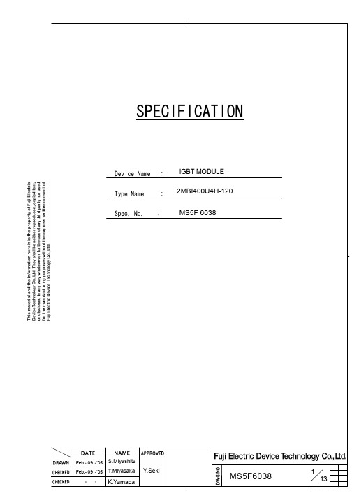
2MBI400U4H-120
9. Definitions of switching time
~ ~
90%
0V
L
0V V GE tr r Ir r
90%
~ ~
VCE
V cc
Ic
90%
RG V GE
V CE Ic
0V 0A
tr ( i ) tr to n to f f
~ ~
Ic
10%
10%
VCE tf
10%
10. Packing and Labeling Display on the packing box - Logo of production - Type name - Lot No - Products quantity in a packing box
SPECIFICATION
Device Name Type Name Spec. No.
: : :
IGBT MODULE
2MBI400U4H-120 MS5F 6038
Feb. 09 ’05 Feb. 09 ’05
S.Miyashita T.Miyasaka
Y.Seki
K.Yamada
MS5F6038
V nF
us
Forward on voltage
V us mΩ
Reverse recovery time IF=400A Lead resistance, R lead terminal-chip (*4) (*4) Biggest internal terminal resistance among arm.
C/W
6. Indication on module Logo of production
400-NS系列无清洗超级拔销线技术数据表说明书

400-NS Series DescriptionThe 400-NS series No-Clean Super Wick are high quality, precision cleaned desoldering braids that were produced with up-to-date and environmentally friendly processes and technology. The high purity copper conducts heat fast, allowing for faster wicking and shorter dwell time that minimizes possible overheating damages.Benefits and Features• Conforms to MIL-F-14256E RMA flux and J-STD-004 • High purity, oxide-free copper• ESD (Electrostatic Dissipative) safe for 1.5 m [5 ft] bobbins • Environmentally and PCB safe residues•Suitable for Use in Food Facilities as a Non-Food Chemical —Canadian and NFS recognition letters available on requestDesoldering Braid Selection GuideFlux PropertiesCompatibilityChemical —the flux residue from the Super Wick is inert under normal conditions. The flux residue can be cleaned with a flux cleaner like the MG 4140 or 413B.400-NS SeriesStorageKeep away from moisture. Shrink wrapping is recommended for extended storage. Store between22 and 27 °C [72 and 81 °F] in dry area away from sunlight.Health, Safety, and Environmental AwarenessPlease see the 400-NS Series Safety Data Sheet (SDS) for more details on transportation, storage, handling and other security guidelines.Health and Safety: The No-Clean Super Wick may cause allergic reactions in some individuals. Avoid breathing fumes produced during desoldering.Other than possible allergic reactions, the flux residue presents no known health or environmental hazard. HMIS® RATING NFPA® 704 CODESApproximate HMIS and NFPA Risk Ratings Legend:0 (Low or none); 1 (Slight); 2 (Moderate); 3 (Serious); 4 (Severe)Braid Desoldering InstructionsWicking works best for the removal of surface solders. This desoldering method is generally not recommended for removal of solder in through plated holes. While the use of desoldering (wicking) braids is not hard, it does require a moderate to advance skill level depending on the project. Novices should practice on scrap pieces before attempting to an actual repair.Equipment and Material Needed•Solder iron equipped with a chisel tip that matches the size of the wick•Damp sponge•Scissors•(Optional) flux—like the MG 8341 No Clean Flux Paste•(Optional) cleaners—like the MG 4140 Flux Remover or 413B Heavy Duty Flux Removers400-NS SeriesPreparation Steps•Remove conformal coating that may be present.•Clean residues/oxides that are present using a flux remover.•For lead-free solder, start with tip temperature of about 315 °C and adjust as necessary.•Choose a braid that matches the size of the solder to be removed. If there are small beads, choosing a wider braid will also speed up the desoldering process.To Remove Surface Solder Array1.Heat up the soldering iron.2.(Optional) Apply flux to the lead or land area.3.Set the braid on the solder to be removed.4.Place the solder tip on the braid, avoiding contact with othercomponents.5.When wicking action has ceased, remove the soldering iron andbraid together in perpendicular motion from the surface.6.Let the area cool, clean the tip with the sponge, and repeatremoval steps as necessary.7.Clean flux residue that may have accumulated.T RICKS: When the solder bead to be removed is very thin, adding a little bit of solder to the joint prior to the removal attempt can help.T RICKS: Cutting an oversized braid at an angle with scissors can help with desoldering small areas.To Put Away the Soldering Iron•Re-tin tip with solder and place the soldering iron on its stand.Supporting ProductsFlux Cleaners•Flux Remover for PC Boards: Cat. No. 4140-P, 4140-1L, 4140-4L, 4140-20L•Heavy Duty Flux Remover: Cat. No. 413B-1L, 413B-4L, 413B-20LThinners & Conformal Coating Removers•Thinner 2: Cat. No. 4352-945ML, 4352-4L (1 gal), 4352-20L, 4352-200L•Conformal Coating Stripper: Cat. No. 8310-100MLTip Tinner•Tip Tinner: Cat. No. 4190-28GElectronic Cleaners•Safety Wash Electronics Cleaner: Cat. No. 4050A-340G, 4050-1L, 4050-4L, 4050-20L•Superwash Cleaner Degreaser: Cat. No. 406B-450G•Isopropyl Alcohol: Cat. No. 824400-NS SeriesTechnical SupportContact us regarding any questions, improvement suggestions, or problems with this product. Application notes, instructions, and FAQs are located at .Email: ***********************Phone: +(1) 800-340-0772 (Canada, Mexico & USA)+(1) 905-331-1396 (International)Fax: +(1) 905-331-2862 or +(1) 800-340-0773Mailing address: Manufacturing & Support Head Office1210 Corporate Drive 9347–193rd StreetBurlington, Ontario, Canada Surrey, British Columbia, CanadaL7L 5R6 V4N 4E7WarrantyM.G. Chemicals Ltd. warranties this product for 12 months from the date of purchase by the end user. M.G. Chemicals Ltd. makes no claims as to shelf life of this product for the warranty. The liability of M.G. Chemicals Ltd. whether based on its warranty, contracts, or otherwise shall in no case include incidental or consequential damage.DisclaimerThis information is believed to be accurate. It is intended for professional end users having the skills to evaluate and use the data properly. M.G. Chemicals Ltd. does not guarantee the accuracy of the data and assumes no liability in connection with damages incurred while using it.。
ERJ120102Y中文资料(panasonic)中文数据手册「EasyDatasheet - 矽搜」
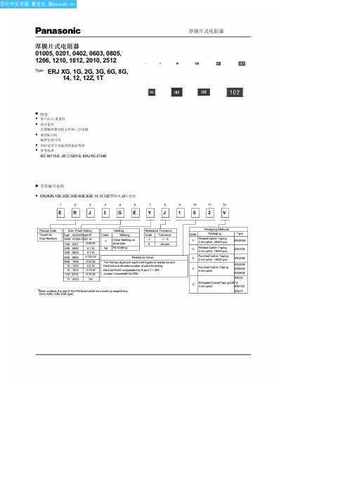
3GE : 0603 0.1 W
6GE : 0805 0.125 W
8GE : 1206 0.25 W
14 : 1210 0.5 W
12 : 1812 0.75 W
12Z : 2010 0.75 W
1T : 2512
1W
Marking
Code
Marking
Y Value Marking on black side
U
Embossed CarrierTaping ERJ12
4 mm pitch
ERJ12Z
ERJ1T
芯片中文手册,看全文,戳
厚膜片式电阻器
■ 施工
Protective coating Alumina substrate
Thick film resistive element
■ 额定值
3.6到4
6.2 to 7
ERJ1T(2512)
5至5.4
7.6至8.6
c 0.20 to 0.25 0.25 to 0.35 0.4到0.6
0.8至1 0.9 to 1.4 1.2至1.8 1.8到2.8 2.3 to 3.5 1.8到2.8 2.3 to 3.5
■ 推荐焊接条件
建议及注意事项如下所述.
0.20
0.10
0.10
0.13
0.04
ERJ1G (0201)
0.60
0.30
0.10
0.15
0.23
0.15
ERJ2G (0402)
1.00
0.50
0.20
0.25
0.35
0.8
ERJ3G (0603)
1.60
0.80
0.30
压电材料与应用

d33 (PC/N) 430 515 490 550 410 520 540 630 670 680 750
g33 (×10- 3Vm/N) 34.7 30 28 30.5 24.4 24.2 22.2 24.5 21.6 22.0 24
PZT-5 PZT-5A
PZT-5B S1-1 S1-3D PZT-5J Sm-16 Sm-32 PZT-5H Sm-32A Sm-32B Sm-32C
压电陶瓷系统
3.NaNbO3基无铅压电陶瓷 A(1-x)NaNbO3-xAINb2O6 b(1-x)NaNbO3-xAITiO3 4.铋层状结构压电陶瓷 a Bi4Ti3O12基无铅压电陶瓷 b MBi4Ti4O15基无铅压电陶瓷 c MBi2Nb2O9基无铅压电陶瓷(M=Sr、Ca、Ba、 Na0.5Bi0.5等) d 复合铋层状结构压电陶瓷
主要用途:各种检测传感器,如压力计流量计风速计等;水声换能器;医用换能器;电声器件和点火器等等。 商 品 名
材料 Kp Sn-8 S1-01 S33 S34 0.64 0.665 0.69 0.73 0.62 0.67 0.65 0.63 0.68 0.67 0.73 / 0.51 0.50 0.54 / / / / / 0.51 0.51 Kt
压电材料性能指标
Kt
Kp
K33 K15 K31
3、机械品质因数Qm
压电材料性能指标
压电陶瓷在振动时,为了克服内摩擦需要消耗能量。机械品质因数 Qm 是反映能量消耗大小的一个参数。Qm越大,能量消耗越小。机械品质因数 Qm的定义式是:
Qm 2 谐振时振子储存的机械 能 每一谐振周期振子所消 耗的机械能
压电聚合物
优点:低声学阻抗特性,柔软可做极薄的组件。 缺点:压电参数小,需极高的极化电场(MV/mm)
米亚基直流逆变焊接电源IS-120B-B说明书
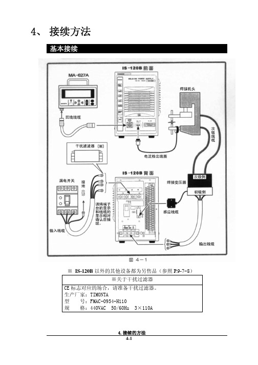
4、 接续方法基本接续※ IS-120B以外的其他设备都为另售品(参照P.9-7~8)※关于干扰过滤器CE标志对应的场合,请准备干扰过滤器。
生产厂家:TIMONTA型 号:FMAC-0954-H110规 格:440VAC 50/60Hz 3×110A接续步骤① 连接变压器请用输出电缆接续背面面板上的[焊接电源输出端子台]和焊接变压器的初级侧。
使用本公司的焊接变压器的场合请将信号电缆接续至[焊接变压器I/O信号]的接续接口上,连接焊接变压器。
使用其他公司的焊接变压器的场合请进行步骤⑤的作业。
② 连接电源用输入线缆(参照P.9-7)将焊接电源接续至背面面板的[焊接电源输入断路器]上。
请将PE端子接地。
③ 在[外部输入输出信号接续端子台]上接续必要的线缆。
请参照P.5-1准备接续用的线缆。
④连接编程操作器将回线线缆接续到正面面板的[编程操作器]接续接口上。
【使用其他公司的变压器的场合,请进行以下的操作】⑤ 连接次级电流检出用的检出线圈将检出线圈接续至正面面板的[检出线圈]接口上。
5、 接 口(1)外部输入输出信号的接续图外部输入输出信号端子台的规格额定电压 AC125V 以上耐电压 1200V 以上安装可能压着端子 最大2个压着端子尺寸 M3或M3.5(宽7.1)鼓励线缆截面积 端子No.1~5 →0.75mm 2以上 端子No.6~31→0.5mm 2以上*RY1~RY3规格型号G6B1114P(OMRON)线圈电压DC24V接点容量AC110V 0.5A(2)外部输入输出信号的说明(3)输入信号的接续方法电磁阀用电源输入为AC100V状态下使用的场合,请将1~5AC线和6~31的信号线分离后配线。
注意在下述①②③的使用场合,请根据用途接续附属的短路线。
在下述④的使用场合,请不要在6、7号接线柱上接续任何东西。
如果接续错误,会引起故障。
① 外部输入信号为接点输入的场合② 外部输入信号为接点输入的场合5. 接 口③ 外部输入信号为正COM输入的场合④ 外部电源供给输入的场合5. 接 口7、 时序图T1:[SCHEDULE]画面的[DELAY-START SET]中所设定的时间T2:约200ms(终了信号在起动信号处于ON状态期间或者200ms期间输出) T3:约80ms(此间不进行下次起动)8、 维护保养电池的更换本装置中使用的锂电池寿命为5年。
(完整版)Monel400执行标准Monel400化学成分
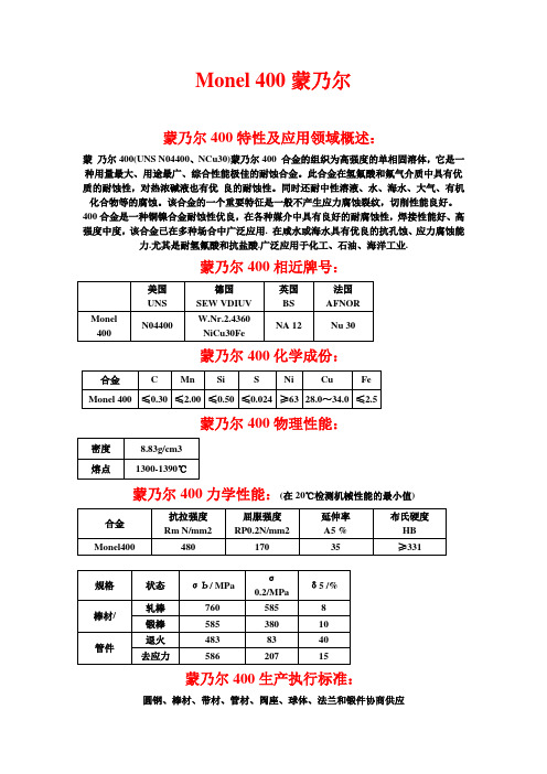
Monel 400蒙乃尔蒙乃尔400特性及应用领域概述:蒙乃尔400(UNS N04400、NCu30)蒙乃尔400 合金的组织为高强度的单相固溶体,它是一种用量最大、用途最广、综合性能极佳的耐蚀合金。
此合金在氢氟酸和氟气介质中具有优质的耐蚀性,对热浓碱液也有优良的耐蚀性。
同时还耐中性溶液、水、海水、大气、有机化合物等的腐蚀。
该合金的一个重要特征是一般不产生应力腐蚀裂纹,切削性能良好。
400合金是一种铜镍合金耐蚀性优良,在各种媒介中具有良好的耐腐蚀性,焊接性能好、高强度中度,该合金已在多种场合中广泛应用. 在咸水或海水具有优良的抗孔蚀、应力腐蚀能力.尤其是耐氢氟酸和抗盐酸.广泛应用于化工、石油、海洋工业.蒙乃尔400相近牌号:蒙乃尔400 化学成份:蒙乃尔400物理性能:蒙乃尔400力学性能:(在20℃检测机械性能的最小值)蒙乃尔400生产执行标准:圆钢、棒材、带材、管材、阀座、球体、法兰和锻件协商供应蒙乃尔400 金相组织结构:Monel400合金的组织为高强度的单相固溶体。
蒙乃尔400工艺性能与要求:热加工退火温度应控制在700-900 ℃,推荐快速空冷以得到最佳耐腐蚀性能。
时间和温度将直接影响最终晶粒度,必须仔细制定退火参数。
冷加工冷加工应进行中间退火。
具有较高加工硬化率冷成形变形量要高于5%,必须在去应力或退火后才能使用Monel400焊接工艺可用氩弧焊、等离子体电弧,气体保护焊或手弧焊等方法进行焊接,首推脉冲电弧焊,焊后最好进行表面处理。
应用范围.Monel400合金是一种多用途的材料,在许多工业领域都能应用:1.动力工厂中的无缝输水管、蒸汽管2.海水交换器和蒸发器3.硫酸和盐酸环境4.原油蒸馏5.在海水使用设备的泵轴和螺旋桨6.核工业用于制造铀提炼和同位素分离的设备7.制造生产盐酸设备使用的泵和阀。