DSP数字前级放大器G1说明书
声韵音响vega-g1说明书
版权所有,不得翻印 © 2008-2018 声韵音响版权所有。
本出版物的任何部分,包括但不仅限于,图片,文字,代码还是交互功能,未经声韵音响或其授权人的书面许可,不得复制。
本手册仅作提供信息之用,而不应被视为一种承诺。
声韵音响有权对各种细节进行变更,不必另行通知。
声韵音响对可能出现在本手册中的错误不承担责任。
AURALiC, inspire the music, Lightning Streaming, Purer-Power, ORFEO以及它们的图标是声韵音响的注册商标。
这些商标或商业外观不得以任何可能引起消费者混淆的方式,或任何贬低、诽谤声韵音响的方式用于与本网站以及声韵音响无关的任何产品或服务上。
本网站上的非声韵音响持有的商标,是其商标权利人所独有的财产,这些权利人可能与本网站有相应的关系,或由声韵音响所赞助。
未经声韵音响或相关商标所有人的书面许可,本网站上的任何内容都不应被解释为以默许或其他方式授予许可而使用本网站上出现的商标的权利。
目录符合标准说明 (4)关于保修 (5)包装清单 (5)放置和线缆连接方式 (6)放置 (6)检查您的交流电电压 (6)线缆连接方式 (7)前面板 (8)使用您的 VEGA G1 (9)启动和休眠 (9)欢迎界面 (9)主菜单 (10)正在播放 (11)列表 (12)系统 (13)流媒体播放器 (14)输入 (14)Lightning 网页控制界面 (15)为iOS开发的Lightning DS (15)使用其他软件 (16)使用VEGA G1作为USB解码器 (16)使用VEGA G1作为流媒体播放器 (16)开始使用Lightning DS控制软件 (17)智能红外遥控 (19)维修服务 (19)联系方式 (20)规格 (21)AURALiC产品登记表 (22)重要安全提示●在开始使用之前,请先阅读说明书中的注意事项和使用说明,并请关注我们未来发布的相关信息。
DSP中文说明书

一、产品概述DSP系列电磁卸荷油脂泵是用直流或交流电源驱动的油脂泵,它通过交(直)流电机和机械传动使柱塞往复运动,将润滑脂不断输出。
该泵最大特点是带有电磁卸荷阀,可与DPQ、DPQX型等干油定量注油器配合使用。
通过程控器,可将润滑脂定时、定量地输送至各润滑点。
该泵内置溢流阀,可有效地保护润滑系统。
该系列润滑泵输出流量大,广泛应用于塑料、行走机械、锻压、工程等机械设备的间隙集中润滑系统。
二、工作原理电动机(直流或交流)带动齿轮减速,通过偏心轮及连杆机构,使柱塞作往复运动。
润滑脂通过吸、排油过程,经过单向阀,一路润滑脂经出油口进入PDI润滑系统,另一路通过卸荷阀(通电时卸荷阀关闭,断电时卸荷阀打开卸荷)回到油罐中。
在PDI润滑系统中,当定量注油器充满润滑脂后,经过一段时间的延时,系统末端的压力开关发出信号给程控器,程控器发出信号给电动机,电动机停止运行,同时,电磁卸荷阀断电卸荷,润滑系统管路中的油脂卸压,定量注油器完成一次注油过程。
三、技术参数出油口螺纹:内NPT1/8使用温度范围:-20℃~60℃加油口形式:快换充脂接头充脂范围:NLGI000#~1#(如在低温下使用,要用低温润滑脂)溢流阀设定压力为10MPa,使用时需确认所接系统定量分配器的最大工作压力,调节溢流阀,使泵的出油口压力与所接系统压力相匹配。
四、外形尺寸DSP-1(带卸荷阀)原理图DSP-1(0.7升)DSP-1(1升)DSP-2(不带卸荷阀)原理图DSP-2(0.7升)DSP-2(2升)五、安装与调试a.电磁卸荷泵的安装与调试1.按照上面外形图的安装尺寸将泵固定好;2.通过充脂口给油泵加油,务必使用指定粘度范围内的清洁润滑脂;3.将电机、电磁卸荷阀、液位开关及电源线按要求接入程序控制器内相应的端子(注意电源电压应与电机、卸荷阀电压相符);4.检查被试泵及系统各接头连接处是否有渗漏,确认程控器、电源以及电磁卸荷阀之间是否按接线要求正确接线;5.开启泵,用扳手旋松“排气阀”排气(注意:人员应避免正对排气口),运行一段时间,将泵体内的空气排尽,直至排气阀口有连续油脂冒出,旋紧排气阀螺钉,接上管路使用;6.切勿将泵体过度倾斜或倒立;7.所有机型电机单次运行时间不大于1分钟,停机时间不小于10分钟。
放大器操作说明

放大器操作说明一、放大器的设置1.打开Nexus 元件的电源并使Nexus 元件初始化。
2.如果Nexus 元件没有显示主菜单,则应按底下的“Home ”键,直到出现主菜单。
在主菜单上应有诸如“Amplifier Set -up (放大器设置)”,“Transducer Set -up (传感器设置)”等选项。
如照片1所示:3.滚动到“Amplifier Set -up (放大器设置)”并按底下的“↙”一次。
如照片2所示:照片 1照片 24.在“Amplifier Set -up (放大器设置)”菜单下,应通过在底下箭头键来滚动到“Hz ”,以确保“Hz ”显示加亮。
一旦“Hz ”显示加亮,则按 “Ch ↓”键。
随后应用“+”和“-”按键来设置Hz (频率)为A 。
一旦通道1设置为A ,则应按 “Ch ↓”键,并对通道2,3和4作同样的工作。
如果是2通道Nexus 元件,那么只需要编程两个通道。
当所有通道设置为A 时,按“Home ”键返回。
如照片3所示:然后,用“→”键移动到“Out (输出)”。
一旦“Out (输出)”被显示加亮,使用“Ch ↓”键和“+”与“-”键把每个通道都设置为316mV/Pa 。
当所有通道都设置为316mV/Pa 后,按“Home ”键返回。
最后回顾一下菜单,确保所有的通道都被分别设置在A 下,“Out ”输出为316 mV/Pa 。
当所有设置项都设置正确后,按“Home ”键返回。
如照片4所示:照片 3滚动到“Transducer Set -up (传感器设置)”下并按底下的“↙”一次。
如照片5所示:(此步可以省略,因为麦克风的灵敏度是自动识别的不用设置)编辑此菜单需要声学传感器的校准数值。
当得到校准数值后,滚动到“Sensitivity (灵敏度)”并按“Ch ↓”键。
如照片6所示:照片 4照片 5随后将处在显示加亮的十进制数值的通道#1。
用“+”与“-”键把此数值设置为对应于此通道/声学传感器的校准/灵敏度数值。
DSP3000卡拉OK数码前置效果器说明书
卡拉OK数码前置效果器使用说明书◆高性能DSP处理麦克风效果◆内置高性能AD/DA转换器◆1M大容量内存保证真实的处理效果◆麦克风音量独立调节◆麦克风音调调节◆液晶显示屏显示◆两路音乐信号输入◆输出匹配电平调节◆频点可调超低音输出◆平衡式输出端子◆宽电源电压,交流110V~240V输入专业级数码效果处理器PROFESSIONAL DSP DIGITAL PROCESSOR前言感谢您选用我们的专业数码卡拉OK效果处理器,您选择我们的产品,充分显示了您对此产品的专业眼光。
为了您能更好的熟悉和使用本产品,请仔细阅读说明书。
本专业卡拉OK效果处理器是专为卡拉OK演唱而设计的信号处理前级设备。
本机采用优质的贴片元件和先进的焊接技术以保证整机的可靠性。
为了进一步提升卡拉OK演唱效果,采用了DSP(数字信号处理器)做卡拉混响处理,通过虚拟的声学算法,产生极佳的空间感和清晰的回声,比一般的单一回声效果器更加清澈自然,使演唱更加感性化。
由于使用了高质量的DAC和ADC以及1M的大容量的内存,所以消除了一般在卡拉OK机都存在的混响部分的性能瓶颈,整机的信噪比,失真,频率响应等指标都很高。
性能参数线路输入阻抗:>10KΩ麦克风输入阻抗:600Ω线路最大输入电平:+16dBu 麦克风输入灵敏度:10mV 输出阻抗:50Ω最大输出电平:20dBu线路输入频率响应:20Hz-50KHz±0.5Db线路输入信噪比:>80Db麦克风输入信噪比:>75Db总谐波失真:<0.1%D/A转换器:24BlT/48KHz△-ΣA/D转换器:24BlT/48KHz△-Σ显示:2X16 LCD电源电压: AC110V~240V 50/60Hz耗电: <12W操作与说明操作方法:1.正确连接好设备之间的信号线和电源线。
将音乐信号源连接到后板上的AUX1或AUX2插口,将麦克风连接至前面板或后板上的MlC1,MlC2或MlC3输入接口,再用专门的连接线将线输出LEFT OUT,RlGHT OUT及BASS OUT接口与外部功率放大器的相应输入端连起来。
效果器中文说明书大全
效果器中文说明书大全在这里我将为大家搜集各种常用的效果器中文说明书以后会不断的补充新的说明书POD 2.0中文说明,音色列表,以及相关所有资料Line 6 POD 2.0 控制与连接中文简易说明 1 开关- 在POD 2.0右侧。
按下它可以开启你的POD2.0。
2 输入- 在POD 2.0右下侧。
把你的吉他连接在这里。
3 耳机接口- 在POD 2.0的左下侧。
连接你的耳机以做静音练习。
音量由OUTPUT控制。
其耳机放大器可供所有型号的耳机使用。
4 输出- 在POD 2.0面板的最左边(OUTPUT)。
控制主输出音量。
当储存音色时,这一值是不被记录的。
改变主音量并不改变音色。
《注:在主输出音量开到最大时,POD 2.0会给您最佳的信噪比。
相反,当主音量开得较小时,会出现嘶噪。
所以当您录音时,尽量将您的OUTPUT开到最大。
请确定您所连接的设备的输入口属于“线输入”(LINE LEVEL), 而不是麦克风/吉他输入。
线输入可以允许POD 2.0的总输出开到最大(或接近最大)从而得到最佳的音色。
如果您的设备的输入类型为麦克风或吉他,请把输入放到较低,把POD 2.0的输出放到较大。
》 5 左右输出- 在POD 2.0的左上侧。
在左右输出的中间有DIRECT/AMP字样,输出时将你的调音台/录音设备连接到左输出(DIRECT),吉他音箱/监听音箱连接到右输出(AMP) 6 A.I.R Mode拨档- 在POD 2.0的左右输出中间,A. I. R.定向录音输出属Line6独有,专门为直路录音设计,将A.I.R Mode拨档调到左输出(DIRECT)一边即可。
7 踏板接口- 在POD 2.0上方,可与LINE6 Floor Board/FB连接。
POD 2.0不支持LINE6 FBV4. 8 MIDI输入与输出- 在POD 2.0右上方。
通过MIDI线与MIDI设备间接9 Drive- 其控制您所选择的放大器(Amp)的Drive。
百灵达dsp1000效果器使用说明书
百灵达BEH RINGE R DSP1000效果器使用说明一、面板和功能键(1)双排发光二极管电平显示。
(2)效果类型菜单。
(3)显示屏:开机后即显示上一次使用的效果号码,它还可以显示各种参数。
(4)调节旋轮:可用于调整各种参数,顺时针为增加;逆时针为减少。
(5)效果键(EFFECT):直接选择所给的32种效果。
(6)变化键(VARIATION):可以改变主要效果参数,如混响时间等。
(7)左声道启动(ENGINE L):用于选择左声道。
(8)右声道启动(ENGINE R):用于选择右声道。
(7)、(8)一起按时,左右声道联控,一般应选择联控方式。
(9)编辑A(EDIT A):每种预置可以编辑两个参数。
编辑A键选择第一个参数。
(10)编辑B(EDIT B):当需要时,可以转换到第二个参数进行编辑。
(11)低频均衡(EQ LO):用于提升或衰减低音部分。
(12)高频均衡(EQ HI):用于提升或衰减高音部分。
(13)旁路键(IN/OUT):加与不加效果选择,其绿色指示灯亮,则说明在加效果。
(14)存储键(STORE):可用于存储参数,按此键时,显示屏上闪烁的数码告诉用户将参数存在第几号存储中,可用旋轮选择存储号码(从1-100)。
(15)电源开关(POWER)。
二、键结合功能*开机前,同时按EFFECT(效果)键和STORE(存储)键;开机后,保持两秒钟,原程序数据被消除。
*同时按EQ LO和EQ HI键,进入MIX(混合)调整模式(MIX用于调整效果声比例)。
按两个EQ键,保持两秒钟,可在内部混合和外部混合(效果声比例为100%,用于输入、输出接法,后面将介绍)之间选择。
内部混合可从0-100%之间任意调整,但20%-50%之间较好。
*同时按IN/OUT键和S TORE键约两秒钟,进入MIDI工作模式。
TBMDA3B 调制功率放大器 10MHz – 1GHz 说明书
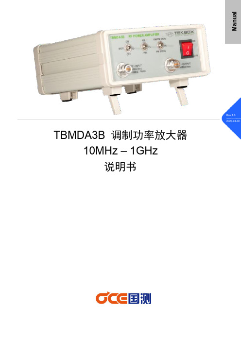
TBMDA3B 调制功率放大器10MHz – 1GHz说明书M a n u a l1、简介TBMDA3B 10MHz-1GHz调制功率放大器的设计是为了用于电子构件和产品抗扰度测试的廉价信号源。
它被设计为由频谱分析仪的跟踪发生器输出驱动,输入功率范围-5dBm至0dBm,它可以提高跟踪源的输出功率高达8W。
TBMDA3B调制功率放大器也是驱动TBPS01近场探头的理想选择,以便查找电子电路板的敏感点。
驱动Tekbox TBTC0 TEM小室内部产生高达700 V/m的电场,驱动TBTC1时内部产生400 V/m电场,驱动TBTC2时内部产生200 V/m电场,驱动TBTC3时内部产生130 V/m 电场。
用于抗扰测试信号可以是CW,AM或PM。
因此,TBMDA3B提供了内置的调制能力,生成1 kHz 80%@AM或1KHz 50%占空比PM信号。
在PM模式下,TBMDA3B还可以产生具有12.5% 占空比的217Hz信号,模拟移动电话的TDMA噪声。
正面背面应用:⏹通用增益放大器⏹驱动近场探头/天线/CDN/BCI探头⏹驱动TEM小室特点:⏹CW波连续放大器(调制关闭)⏹ 1 kHz,80%AM调制⏹ 1 kHz,50%占空比脉冲调制⏹217 Hz,12.5%占空比脉冲调制2、技术指标⏹频率范围:10MHz – 1G(5MHz-1.1G可用)⏹最大输入功率:0dBm⏹小信号增益:+42dBm⏹增益平坦度@10MHz-1GHz/Pin= -15dB:2.5dB⏹饱和输出功率@ 5 MHz / Pin = 0 dBm:38.9 dBm (7.8 W) 典型值⏹饱和输出功率@ 10 MHz / Pin = 0 dBm:39.1 dBm (8.2 W) 典型值⏹饱和输出功率@ 50 MHz / Pin = 0 dBm:39.8 dBm (9.5 W) 典型值⏹饱和输出功率@ 75 MHz / Pin = 0 dBm:39.9 dBm (9.8 W) 典型值⏹饱和输出功率@ 100 MHz / Pin = 0 dBm:39.9 dBm (9.7 W) 典型值⏹饱和输出功率@ 250 MHz / Pin = 0 dBm:40.5 dBm (11.2 W) 典型值⏹饱和输出功率@ 500 MHz / Pin = 0 dBm:40.5 dBm (11.2 W) 典型值⏹饱和输出功率@ 750 MHz / Pin = 0 dBm:39.5 dBm (8.9 W) 典型值⏹饱和输出功率@ 1 GHz / Pin = 0 dBm:38.8 dBm (7.6 W) 典型值⏹饱和输出功率@ 1.1 GHz / Pin = 0 dBm:38.3 dBm (6.8 W) 典型值⏹1dB输出压缩点@5MHz:38.2dBm 典型值,(Pin=-2dBm)⏹1dB输出压缩点@10MHz:38.7dBm 典型值,(Pin=-3dBm)⏹1dB输出压缩点@50MHz:39.1dBm 典型值,(Pin=-3dBm)⏹1dB输出压缩点@ 100MHz:39.7dBm 典型值,(Pin=-1dBm)⏹1dB输出压缩点@ 250MHz:39.9dBm 典型值,(Pin=-2dBm)⏹1dB输出压缩点@ 500MHz:39.4dBm 典型值,(Pin=-3dBm)⏹1dB输出压缩点@ 750MHz:38.8dBm 典型值,(Pin=-3dBm)⏹1dB输出压缩点@ 1000MHz:37dBm 典型值,(Pin=-5dBm)⏹1dB输出压缩点@ 1100MHz:36.9dBm 典型值,(Pin=-5dBm)⏹2次谐波,100MHz,Pout=39.9dBm :<-27dBc⏹2次谐波,100MHz,Pout=34dBm :<-13.5dBc⏹3次谐波,100MHz,Pout=39.9dBm :<-12dBc⏹2次谐波,100MHz,Pout=34dBm :<-24dBc总谐波失真⏹18.9% @ 100MHz,Pout = 31dBm 典型值⏹21.8% @ 100MHz,Pout = 34dBm 典型值⏹23.4% @ 100MHz,Pout = 37dBm 典型值⏹31.1% @ 100MHz,Pout = 39.9dBm 典型值⏹三阶输出截距点:44dBm@100MHz,Δ f = 2 MHz,典型值⏹内部调制频率AM: 1 kHz±10%⏹内部调制频率PM: 1 kHz±10%,217 Hz±20%⏹占空比,PM:50%±10%@ 1 kHZ; 12.5%±20%@217 Hz⏹供电电压:5V @典型值,最大5.5V⏹供电方式:USB供电,20W⏹工作温度:-20℃~ +50℃TBMDA3B对输出失配具有很强的耐受性,但不建议负载开路或短路,因为这可能会对输出晶体管造成损坏。
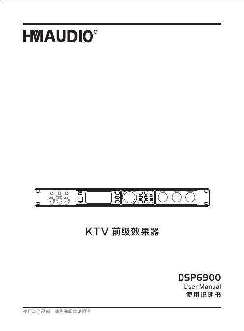
DSP6900 KTV 前级效果器 使用手册说明书
安全使用事项在使用本装置之前,请仔细阅读说明书,并遵守有关操作和使用的警言,本说明书要妥善保管以备日后查用。
◆电源:本装置只能使用说明书所标注的电源种类。
◆电源线保护:要注意避免电源线被重物压挤,特别要注意电源线的插头、装置上的出线处及方便插座处,切忌拉、抽电源线。
◆水口湿气:不能放在离水源较近的地方使用,例如:浴缸、洗漱池、厨房水槽、洗手盆潮湿的地下室、游泳池附近等处。
◆温度:本装置必须远离热源。
例如:散热器、加热电阻、各种炉子及其它发热装置(包括放大器)。
◆电击:必须注意防止物品或水流掉进内芯。
如果掉进金属或其它导电物品,会使装置内部产生电击短路的危险。
◆盖板拆卸:因机内存有高压,非电子专业技术人员,切勿拆卸机壳,如果内部电子零件被非正常接触,可能发生严重电击事故。
此事件本公司概不负责。
◆清洁:不要使用挥发性溶液。
如:酒精、涂料稀释剂、汽油、挥发油等擦拭外壳,使用清洁的干布就行。
◆异常气味:当发现异常气味或浓烟时,应立即切断电源并拔出插头,与供货商或最近的维修部门联系,寻求维修服务。
◆长期闲置时:A.为安全起见,请切断电源开关,拔掉电源插头。
以防发生火灾。
B.防止水、金属、易燃品或其它异物掉进机内,以免发生触电及火灾事故。
若发生此类事故时,请立即切断电源,停止使用。
并与本公司服务中心或所在购买商店联系,寻求维修服务。
◆注意:不要把电源插头压在机器下面或夹在其他物品中间;不要把电源设置在人员来往频繁的地方,以免造成因插头破损而发生触电或火灾事故。
致顾客尊敬的顾客:感谢您选用本产品!为了保证阁下和机器的安全,同时令您能充分享受最佳的音响效果,在连接或操作本机之前务必细读本说明书,阅读后请将本说明书妥善保存好以备日后查用。
开箱检查:拆开包装后,请先确认本机是否有因运输途中造成的损伤,并依照本手册要求接线并测试每项功能,如有问题请立即通知销售部。
◆ 购机时请检查机箱后板上的条形编码是否完整,各随机附件是否齐全 等。
车载DSP音频处理使用说明书

DSP使用说明书MODEL:CARJAZZ-H14X50W高电平输出2路AUX输出7段输入EQ15段输出EQ为了您的安全,请不要在驾驶过程中操作机器与观看本说明书;驾驶车辆时,请将音量调到能清楚听到外界声音水平。
开始操作前,请详细阅读本手册,了解本使用手册和机器上的相关安全提示和警告标识,阅读完之后妥善保管,防止丢失。
首先请注意交通安全:1.如您在操作本机器遇到困难时,请将车辆停靠在安全的地方后操作,勿让儿童操作本机器,以免造成人身伤害或者机器损坏。
2.不要自行保养,维护,安装本机器。
在接通电源的情况下请勿安装或维修本机器,由未受过电子设备或者车辆附件安装训练或缺乏经验的人员安装及维修本机器非常危险。
3.为了保证机器正常运转,请不要将机器暴露在潮湿的空气中,更不能将液体洒落在机器上。
附件:根据您购买的型号包装箱内应放置如下附件,如有缺少,请尽快通知销售商家。
CarJazz H1主机1台说明书1本DSP电脑软件操作说明PC端控制软件为使用者配置机器各参数提供方便的交互环境,可将机器各配置参数存储到磁盘文件中,为进行多台机器或者不同车型的预置场景配置及参数的切换与还原提供了十分方便的手段。
主菜单界面打开主界面后,点击中间的“连接设备”,然后会提示连接成功。
点击【我的】:可以进行设置,升级,和在关于里查看机器的版本号或软件版本号。
点击【保持】:可以对更改的数据保存到电脑或者机器。
点击【打开】:可以从机器里读取数据到电脑并且更新当前音效。
选择通道,每个通道可以单独调节音量,静音。
输出相位的正/反相/延时/高通/低通/直通。
EQ频响曲线调节:可以调节频率,Q值,增益。
(可以直接输入相应的数值)故障排除:电源指示灯未点亮*请确认地线是否连接牢固*确保连接本机的设备电源已打开*确认电池电压*确认机器启动方式无声音输出*检查音量调节,是否被静音*信号源是否有问题#故障无法解决时请及时联系经销商注:本公司保留对本说明书法律解释权。
DSP中文说明书

一、产品概述DSP系列电磁卸荷油脂泵是用直流或交流电源驱动的油脂泵,它通过交(直)流电机和机械传动使柱塞往复运动,将润滑脂不断输出。
该泵最大特点是带有电磁卸荷阀,可与DPQ、DPQX型等干油定量注油器配合使用。
通过程控器,可将润滑脂定时、定量地输送至各润滑点。
该泵内置溢流阀,可有效地保护润滑系统。
该系列润滑泵输出流量大,广泛应用于塑料、行走机械、锻压、工程等机械设备的间隙集中润滑系统。
二、工作原理电动机(直流或交流)带动齿轮减速,通过偏心轮及连杆机构,使柱塞作往复运动。
润滑脂通过吸、排油过程,经过单向阀,一路润滑脂经出油口进入PDI润滑系统,另一路通过卸荷阀(通电时卸荷阀关闭,断电时卸荷阀打开卸荷)回到油罐中。
在PDI润滑系统中,当定量注油器充满润滑脂后,经过一段时间的延时,系统末端的压力开关发出信号给程控器,程控器发出信号给电动机,电动机停止运行,同时,电磁卸荷阀断电卸荷,润滑系统管路中的油脂卸压,定量注油器完成一次注油过程。
三、技术参数出油口螺纹:内NPT1/8使用温度范围:-20℃~60℃加油口形式:快换充脂接头充脂范围:NLGI000#~1#(如在低温下使用,要用低温润滑脂)溢流阀设定压力为10MPa,使用时需确认所接系统定量分配器的最大工作压力,调节溢流阀,使泵的出油口压力与所接系统压力相匹配。
四、外形尺寸DSP-1(带卸荷阀)原理图DSP-1(0.7升)DSP-1(1升)DSP-2(不带卸荷阀)原理图DSP-2(0.7升)DSP-2(2升)五、安装与调试a.电磁卸荷泵的安装与调试1.按照上面外形图的安装尺寸将泵固定好;2.通过充脂口给油泵加油,务必使用指定粘度范围内的清洁润滑脂;3.将电机、电磁卸荷阀、液位开关及电源线按要求接入程序控制器内相应的端子(注意电源电压应与电机、卸荷阀电压相符);4.检查被试泵及系统各接头连接处是否有渗漏,确认程控器、电源以及电磁卸荷阀之间是否按接线要求正确接线;5.开启泵,用扳手旋松“排气阀”排气(注意:人员应避免正对排气口),运行一段时间,将泵体内的空气排尽,直至排气阀口有连续油脂冒出,旋紧排气阀螺钉,接上管路使用;6.切勿将泵体过度倾斜或倒立;7.所有机型电机单次运行时间不大于1分钟,停机时间不小于10分钟。
专业功率放大器的使用说明书

使用说明书专业功率放大器User’s Manual目录2345768故障现象目录1注意事项格的AC 电源插座。
否则可能会导致火灾或触电。
电。
液体或细小金属物品落入本装置内可能会导致火灾或触电。
电源线,进而导致火灾或触电。
特别注意,切勿将重物压在被地毯覆盖的电源线上。
勿划伤、弯折、扭曲、拉伸或加热电源线。
否则可能会损伤电源线,进而导致火灾或触电。
勿打开本装置罩壳。
否则可能导致触电。
如果认为内部需要检修、维护保养或修理,请与代理经销商联系。
—暴露在飞溅的油沫、蒸汽之下,如靠近厨灶、增湿器等地方。
—不稳定的表面,如摇晃的桌面或斜面。
—暴露在过热环境下,如窗户紧闭的车内或受阳光直射的地方。
—暴露在高潮湿的环境下或灰尘积聚的地方。
灾或触电。
AC 电源插座拔出电源插头时请抓住插头部分。
切勿直接拽拉缆线。
否则可能会损伤电源线,进而导致火灾或触电。
装置在正面和背面都有通风孔,以避免内部温度升得过高。
请勿阻塞这些通风孔。
阻塞通风孔可能会导致火灾。
特别注意,切勿—将本装置侧放或倒放,—将本装置放在通风不良的地方,如书橱或壁橱(而不是安装在附带的专用支架上),用桌布覆盖本装置,或将它放在地毯以及床上。
请勿擅自改造本装置。
否则可能会导致火灾或触电。
如果出现闪电雷击,请尽快关闭本装置电源开关,并从电源插座拔出电源电缆的插头。
如果可能出现闪电,在接插状态请勿触碰电源电缆的插头,否则可能导致触电。
若电源线损坏(如切断或芯线裸露),请从代理经销商获取更换品。
用损伤的电源线继续使用本装置可能会导致火灾或触电。
若本装置从高处跌落或外壳损坏,请立即关闭电源开关,从A C 电源插座拔出电源插头,并与代理经销商联系。
若忽视本条注意事项继续使用,可能会导致火灾或触电。
当发现任何异常时,如冒烟、异味、噪音或有异物、液体进入装置内部,请立即关闭电源开关。
并将电源线插头从A C 电源插座中拔出。
请代理经销商代为修理。
这时若继续使用可能会导致火灾或触电。
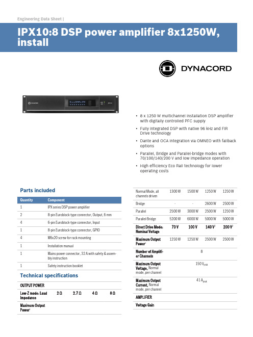
霍普金德IPX10 8数字控制DSP扬声器电源放大器说明书
Engineering Data Sheet |▪8 x 1250 W multichannel installation DSP amplifierwith digitally controlled PFC supply▪Fully integrated DSP with native 96 kHz and FIRDrive technology▪Dante and OCA integration via OMNEO with fallbackoptions▪Parallel, Bridge and Parallel-bridge modes with70/100/140/200 V and low impedance operation▪High efficiency Eco Rail technology for loweroperating costsParts included1IPX series DSP power amplifier28-pin Euroblock-type connector, Output, 6 mm 46-pin Euroblock-type connector, Input18-pin Euroblock-type connector, GPIO4M6x20 screw for rack mounting1Installation manual1Mains power connector, 32 A with safety & assem-bly instruction1Safety instruction bookletTechnical specificationsOUTPUT POWERLow-Z mode: LoadImpedance2 Ω 2.7 Ω 4 Ω8 ΩMaximum OutputPower1Normal Mode, allchannels driven1300 W1500 W1250 W1250 WBridge--2600 W2500 W Parallel2500 W3000 W2500 W1250 W Parallel-Bridge5200 W6000 W5000 W5000 W Direct Drive Mode:Nominal Voltage70 V100 V140 V2200 V2Maximum OutputPower11250 W1250 W2500 W2500 WNumber of Amplifi-er Channels8Maximum OutputVoltage, Normalmode, per channel150 V peakMaximum OutputCurrent, Normalmode, per channel41 A peakAMPLIFIERVoltage GainLow-Z mode, ref.1kHz32.0 dB, adjustable 20.0-44.0 dBDirect Drive mode33.2/36.2/39.2/42.2 dB for70/100/140/200 VInput SensitivityLow-Z mode, Max.Output Voltage10.7 dBu (2.66 V), adjustable -1.3-22.7 dBu Direct Drive mode 6 dBu (1.55 V), fixedTHD3 dB below max,AES17, 1 kHz< 0.05 %DIM 1003.15 kHz, 15 kHz< 0.15 %IMD-SMPTE60 Hz, 7 kHz< 0.05 %Crosstalkref. 1 kHz, 12 dBbelow Max, 8 Ω< -80 dBFrequency Re-sponseref. 1 kHz, analog into speaker out20 Hz to 20 kHz (±0.5 dB)Damping Factor20 Hz to 200 Hz, 8Ω> 400Output Stage Top-ologyClass D, fixed frequencySignal to Noise Ra-tio AmplifierA-weighted, analoginput112 dBA-weighted, digitalinput115 dBOutput NoiseA-weighted, analoginput< -70 dBuA-weighted, digitalinput< -73 dBu CONNECTIVITYAnalog Audio In-put/ThruType 4 x 6-pin Euroblock, male Maximum Input Lev-el+21 dBuInput Impedance, active balanced 20 kΩReference levelequal to digital in-put+21 dBu for 0 dBFSSpeaker Output 2 x 8-pin Euroblock, 6 mm, femaleGENERALPower Consump-tionRated power con-sumption (see BTUtable)1300 W1/8 Maximum Out-put Power at 4 Ω1780 WIdle Mode (no inputsignal)105 WStandby Mode< 18 WDimensions(W x H x D), mm483 x 88.1 x 514.2Weight16.8 kg (37.1 lb)Shipping Weight19.1 kg (42.1 lb)DIGITAL SIGNAL PROCESSINGSampling rate48 kHz/96 kHz, OMNEO/Dante synchronizedSignal delay/laten-cyAnalog In to Speak-er Out, 48 kHz/96kHz0.70 ms/0.53 msDante Network La-tencytyp. 1.00 msSignal ProcessingUser EQ12 filters per channel, selectable as PEQ, Lo-Shelv, Hi-Shelv, Lo-ShelvQ, Hi-ShelvQ, Hi-Pass,Lo-Pass and Notch; 2 filters of them with addi-tional asymmetric filter typeUser Delay0 to 2000 ms per channel (units: µs, ms, s, cm,m, inches, feet)Array EQ 5 filters per channel, selectable as PEQ, Lo-Shelv, Hi-Shelv, Lo-ShelvQ, Hi-ShelvQ, Hi-Pass,Lo-Pass, and All-PassArray Delay0 to 500 ms per channel (units: µs, ms, s, cm,m, inches, feet)Speaker EQ10 filters per channel, selectable as PEQ, Lo-Shelv, Hi-Shelv, Hi-Pass, Lo-Pass and All-PassSpeaker X-Over Hi-Pass, and Lo-Pass per channel,6/12/18/24/30/36/42/48 dB Bessel/Butter-worth, 12/24/48 dB Linkwitz-Riley; AlignmentDelay, 0 to 20 ms per channelSpeaker FIR Up to 1025 taps, Linear Phase Filter, LinearPhase Brickwall X-OverSpeaker Limiters Peak Anticipation Limiter and RMS/TEMP Limit-er per channelOther Functions Source Selection and Mix, Level, Mute, Polarity,Sine and Noise Generator, Pilot Tone Generatorand Detection, Level Meters, Impedance Meas-urement and Load MonitoringMemoryDSP Presets 1 Factory + 20 UserSpeaker-Pool Pre-sets30 Speaker SettingsSource Supervi-sion and Fallback Pilot Tone supervision at Analog and OMNEO/ Dante inputs, switchover to alternative Source SelectionCONNECTIVITYNetworkType 2 x Neutrik EtherCON/RJ45, redundant PRI-MARY/SECONDARYGeneral1000base-T/100base-TX, integrated switch Network Audio In-puts8 channels, 48/96 kHz, OMNEO/Dante formatNetwork Audio Out-puts (Monitor)2 channels, 48/96 kHz, OMNEO/Dante format Mains Input 1 x Neutrik powerCON-HCGPIO Control PortType 1 x 8-pin Euroblock, malePorts and Operating Modes 3 x GPIO, switchable Analog In/Digital In/Digital OutAnalog Input Range0 V to +13 V, 40 kΩ input resistance Digital Input Limits ON: < 1.5 VOFF: > 2.0 V, internal Pull Up (10 kΩ) Digital Outputs ON: Output switched to GND, max. 200 mAOFF: Open Collector (40 kΩ to GND)Reference Voltage Output +10 V, max. 200 mA, supervised, short circuitprotectedREADY/FAULT con-tactGalvanic isolated relay, max. 30 VDC/500mADCGENERALUser InterfaceDisplay Black/white OLED 256 x 64 pixelFront panel indica-tors4 x status LEDs (POWER, STANDBY, FAULT,OMNEO)Front panel operat-ing elements3 buttons (UP, ENTER, DOWN)Rear panel indica-tors1 x status LED (STATUS)Rear panel operat-ing elementsMains SwitchPower Require-ments100 V to 240 V, 50 Hz to 60 Hz ACPower Supply Top-ologySwitching Mode Power Supply with digital con-trolled Power Factor CorrectionProtections Audio Limiters, High Temperature, DC, HF,Short Circuit, Back-EMF, Peak Current Limiters,Inrush Current Limiters, Turn-on Delay, MainsCircuit Breaker Protection, Mains Over-/Undervoltage ProtectionCooling Front-to-rear, temperature controlled fans, su-pervisedAmbient Tempera-ture Limits+5 °C to +40 °C (+40 °F to +105 °F)IEC ProtectionClassClass I (grounded)ElectromagneticalEnvironmentE1, E2, E3Color BlackAmplifier at rated conditions, Low-Z Normal operationmode, all channels driven, 4 Ω loads, Analog input, 32dB Gain, 48 kHz sample rate, unless otherwisespecified.1Test signal for max. output power according IHF-A-202 (Dynamic-Headroom, burst 1 kHz/20 ms on/480ms off/low level -20 dB).2Available in Bridge operation mode only.Block diagram: IPXDimensions: IPXOrdering informationIPX10:8 DSP power amplifier 8x1250W, installDSP power amplifier 8x1250W @ 4 ohms, 8 OMNEO/Dante inputs, 8 analog inputs, hi-z direct drive, GPIOs, euro-block connectors 100 - 240 V, blackOrder number IPX10:8PD32-EU Power distro 3x32A, 230V, CEE 32APower distribution for 3x 32A and 3x 16A, CEE32Amains connector, 3-phase 230/400V, European region, blackOrder number PD32-EUPD30-US Power distro 3x30A, 208V, NEMA L21-30Power distribution for 3x 30A and 3x 15A, NEMAL21-30 mains connector, 3-phase 208V, North American region, blackOrder number PD30-USPCO32A30-US Power cord, powerCon32/NEMA L6-30Power cord, powerCON32 to NEMA L6-30 mainsconnector, 2m, black Order number PCO32A30-USPCO32A16-EU Power cord, powerCon32/CEE7/7 Power cord, powerCON32 to CEE7/7 (Schuko, 16A) mains connector, 2m, blackOrder number PCO32A16-EUPCO32A16-UK Power cord, powerCon32/BS1363 Power cord, powerCON32 to BS1363 (UK-plug) mains connector, 2m, blackOrder number PCO32A16-UKPCO32A10-AU Power cord, powerCon32/AU3-pin10APower cord, powerCON32 to AU, 3-pin 10A mainsconnector, 2m, blackOrder number PCO32A10-AUDC-RMK15 RMK-15Rack Mount Kit for amplifiers, Length 15,5“; 1L/1ROrder number DC-RMK15Germany:Bosch Sicherheitssysteme GmbH Robert-Bosch-Ring 585630 GrasbrunnGermany Bosch Security Systems, Inc.130 Perinton Parkway Fairport, NY 14450USA© Bosch Sicherheitssysteme GmbH, 2018 | Data subject to change without notice Document Number | Vs2 | 24. Apr 2018。
DSP数字前级放大器G1说明书

1DSP 数字前级放大器AS-V1整机特点:■ 高质量的数字效果器,尽显专业水平;■ 音乐信号激励,增强音乐的动感,更有身临其境的感觉; ■ 话筒输入三段均衡,中频扫描; ■ 全平衡话筒输入,抗干扰能力更强; ■ 话筒音色调整;■ 重低音输出,并带扫频功能; ■ 多功能遥控,可外接专用功能控制器。
前面板控制:1.话筒输入插口MIC ,MIC2,MIC3为全平衡6.3mm 标准输入插口。
2.话筒输入增益控制调节对应的电位器,可分别控制MIC1,MIC2,MIC3的输入增益。
3.话筒EQ低频音调:调节该电位器,可改变话筒低频的提升/衰减量,变化量为±15dB 。
中频音调:调节该电位器,可改变话筒中频的提升/衰减量,变化量为±15dB 。
中频扫描:调节该电位器,可改变中频扫描的频率,频率范围250HZ-6KHZ 。
高频音调:调节该电位器,可改变话筒高频的提升/衰减量,变化量为±15dB 。
4.低通滤波器(DSP )显示部分低通滤波器频率范围为8KHZ~18KHZ 连续可调。
5,12. DSP 效果上下滚动按键 内含55种常用OK 效果 6.变调处理按下对应的开关,可对音乐信号进行降调,原调,升调处理。
7. 主音量声象控制:调节该电位器,可将信号以不同量分配到左、右声道上。
主音量高频音调:调节该电位器,可改变主音量高频的提升/衰减量,变化量为±15dB 。
主音量低频音调:调节该电位器,可改变主音量低频的提升/衰减量,变化量为±15dB 。
8.MIC 输出音量控制调节该电位器,可改变话筒输出信号大小。
9.DSP 效果输出音量控制调节该电位器,可改变DSP 效果输出信号大小。
10.主音量输出控制调节该电位器,可改变主音量输出信号大小。
11.电源开关压下电源开关,电源指示灯“ON”点亮,整机进入工作状态。
后面板控制:1.电源输入与市电进行连接,为整机提供电源,请注意市电是否与本机的工作电源相符。
ARRIS 1 GHz MB100 放大器说明书
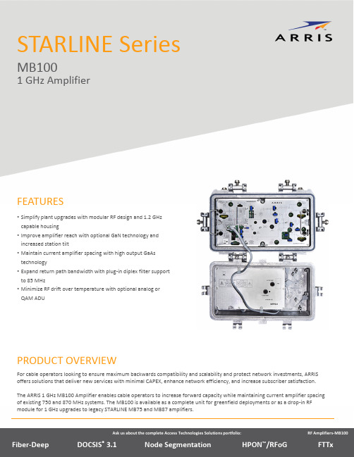
STARLINE SeriesMB1001 GHzAmplifierFor cable operators looking to ensure maximum backwards compatibility and scalability and protect network investments, ARRIS offers solutions that deliver new services with minimal CAPEX, enhance network efficiency, and increase subscriber satisfaction. The ARRIS 1 GHz MB100 Amplifier enables cable operators to increase forward capacity while maintaining current amplifier spacing of existing 750 and 870 MHz systems. The MB100is available as a complete unit for greenfield deployments or as a drop‐in RF module for 1 GHz upgrades to legacy STARLINE MB75 and MB87 amplifiers.PRODUCT OVERVIEWFEATURES•Simplify plant upgrades with modular RF design and 1.2 GHzcapable housing•Improve amplifier reach with optional GaN technology andincreased station tilt•Maintain current amplifier spacing with high output GaAstechnology•Expand return path bandwidth with plug‐in diplex filter supportto 85 MHz•Minimize RF drift over temperature with optional analog orQAM ADUForward PathThe standard MB100 configuration is equipped with second‐generation Enhanced Gallium Arsenide (E‐GaAs) technology with two driven RF outputs, which provides superior distortion performance over standard silicon and competing GaAs technologies. If operators require longer reach, the MB100 can be configured with optional Gallium Nitride (GaN) hybrid technology, which allows for a 3 dB increase in output level over the standard GaAs option.To provide additional system flexibility, easy installation and maintenance, the MB100 is compatible with standard accessories such as attenuators, equalizers, ADUs or QADUs, automotive fuses, and FTEC crowbar circuits. The amplifier maintains output level via an optional plug‐in drive unit. In addition, operators can control level manually, thermally with the TDU (thermal drive unit) accessory, or electronically with the automatic drive unit (ADU). The ADU can support either analog or QAM pilot channels.The MB100 uses modular diplex filters, which operators can change to increase return bandwidth. The following filters are available for use with all US‐style STARLINE RF distribution amplifiers (models BLE, MB/MBV3, BT):•K‐split (5 to 42 MHz/54 to 1003 MHz)•A‐split (5 to 65 MHz/85 to 1003 MHz)•N‐split (5 to 85 MHz/104 to 1003 MHz)Return PathThe MB100comes standard with a high‐gain return amplifier. Operators can select SRE return path equalizers ranging from 0 to 12 dB.Backward CompatibilityOperators can make the MB100 electronics package backward compatible with the 10‐Amp MB*/* housing by installing theMB‐15AII Kit. These kits contain 50 mil gold plated platform assemblies, which make it possible for the amplifier to carry 15 Amperes continuous through its input or output ports.COMPATIBILITYPlatform MB‐550MB‐750D MB‐750SH MB86MB87 Upgrade to MB100No No Yes*Yes*Yes* Requires MB‐15AII KitRELATED PRODUCTSADU/QADU MBV3BLE100BT100SFE/SRE EQ Installation ServicesFlex Max®RF AmplifiersSpecifications –E‐GaAsSpecifications Units Forward ReturnFrequency split1MHz K (54 –1003)A (85 –1003)N (104 –1003)19K (5 –42) A (5 –65) N (5 –85)Flatness 2,19dB±0.75±0.5 Minimum Full Gain 3dB4620 Operation Gain 4dB42NA Manual Bode Slope Control Range 5dB±4NA Noise Figure 6dB98 Standard Slope Reference Frequency MHz1003/550/5435 (flat) Reference Output Level dBmV51/44/37—Operating Interstage Slope7dB14 ±1NA Standard Slope DistortionChannels, Number of NTSC17Composite Triple Beat (CTB) 8,16Cross Modulation (XM) 9,16Composite Second Order(CSO) 8,10,16 Carrier to Intermodulation Noise (CIN)21 Channels, Number of 256 QAMCarrier to Intermodulation Noise (CIN)20,21dBcdBcdBcdBdB7976.568.57165154656807081———Test Point 11dB20 (±1.0 dB)20 (±1.0 dB) Return Loss 12dB14.515 Hum Modulation @ 12A dBc< 60< 60 Hum Modulation @ 15A 12dBc< 60< 65 DC Voltage VDC24Current DC Max. 13mA1600Power Consumption Max.W52AC Input Voltage Range VAC38–90AC Current Draw Max.@ 90 VAC@ 60 VAC@ 38 VAC A0.580.921.45AC Bypass Current (all ports) 14A15Group Delay 15K‐split55.25 to 58.83 MHz nSec52NA Group Delay 15A‐split86.25 to 90.68 MHz nSec28NA Group Delay 19N‐split109.25 to 112.83 MHz 112.25 to 116.68 MHz nSecnSec149NANAOperating Temperature Range °C°F–40 to +60–40 to +140Housing Dimensions, L x W x D InchesMm15.4 x 9.6 x 5.5292 x 244 x 140Weight lbKg156.8Specifications –E‐GaNSpecifications Units Forward ReturnFrequency split1MHz K (54 –1003)A (85 –1003)N (104 –1003)19K (5 –42) A (5 –65) N (5 –85)Flatness 2,19dB±0.75±0.5 Minimum Full Gain 3dB46NA Operation Gain 4dB4220 Manual Bode Slope Control Range 5dB±4NA Noise Figure 6dB98 Ultra Slope Reference Frequency7MHz1003/550/5435 (flat) Reference Output Level dBmV57/48/39—Operating Interstage Slope dB18 ±1NA Ultra Slope DistortionChannels,Number of NTSC17Composite Triple Beat (CTB) 8,16Cross Modulation(XM) 9,16Composite Second Order(CSO) 8,10,16 Carrier to Intermodulation Noise (CIN)21 Channels, Number of 256 QAMCarrier to Intermodulation Noise (CIN)20,21dBcdBcdBcdBdB7970626958154586807081———Standard Slope Reference Frequency 7MHz1003/550/5435 (flat) Reference Output Level dBmV51/44/37—Operating Interstage Slope 6dB14 ±1NA Standard Slope DistortionChannels, Number of NTSC17Composite Triple Beat (CTB) 8,16Cross Modulation (XM) 9,16Composite Second Order(CSO) 8,10,16 Carrier to Intermodulation Noise (CIN)21 Channels, Number of 256 QAMCarrier to Intermodulation Noise (CIN)20,21dBcdBcdBcdBdB7975667166154666807081———Test Point 11dB20 (±1.0 dB)20 (±1.0 dB) Return Loss 12dB14.5 15 Hum Modulation@ 12A dBc< 60<60 Hum Modulation @ 15A 18dBc< 60< 65 DC Voltage VDC24Current DC Max. 13mA1600Power Consumption Max.W52AC Input Voltage Range VAC38–90Specifications –E‐GaN(continued)Specifications Units Forward ReturnAC Current Draw Max.@ 90 VAC@ 60 VAC@ 38 VAC A0.580.921.45AC Bypass Current (all ports) 14A15Group Delay 15K‐split55.25 to 58.83 MHz nSec52NA Group Delay 15A‐split86.25 to 90.68 MHz nSec28NA Group Delay 19N‐split109.25 to 112.83 MHz 112.25 to 116.68 MHz nSecnSec1412NANAOperating temperature range°C°F –40 to +60–40 to +140Housing dimensions, L x W x D inchesmm 15.4 x 9.6 x 5.5 292 x 244 x 140Weight lbkg 15 6.8Notes:1.Operating passband of station. Diplex filters are plugged into the electronic chassis.2.Referenced to the average gain across the passband.3.Minimum full gain at 1003 MHz includes loss of equalizer but Bode slope reserves have not been set. Return gain includes loss of SRE‐*‐4 return equalizer. Measured at Fmaxreturn.4.Includes loss of gain reserves as well as equalizer.5.From midpoint (typical setting is –4 dB at 1003 MHz @ 25 °C). This control should not be used for gain reduction.6.Specified at the housing cable entry facility over temperature and includes the loss of 1 dB for the pre‐stage equalizer. The return noise figure includes the station loss preceding theRF hybrid.7.Amount of slope created and cable equivalence of fixed, plug‐in interstage equalizer.8.Measured with CW carriers and spectrum analyzer over specified temperature range. References the worst‐case channel.*9.Measured with wave analyzer and synchronous, 100% depth modulated channels. References the worst‐case channels over specified temperature range.*10.Refers only to beat clusters that fall 0.75 MHz and 1.25 MHz above the subject picture carrier.11.Test points should be used with GFAL adapter.12.Match measurement at the station input and output, cable‐entry facilities, at the specified passband for operational gain.13.Current draw at 24 VDC.14.Stated in RMS continuous.15.Specified for standard NTSC video, where delay is the delta from picture carrier to 3.58 MHz color subcarrier. Reverse delay is in a 1.5 MHz bandwidth.16.Worst‐case over temperature in a cascade.17.NTSC 79 Channel forward, 75 QAM carriers –6dB relative to analog CW carriers. 6 Channel return.18.Specification is 55 from 5 to 10MHz at 15A.19.For N‐split (5–85/104–1003MHz) roll‐off from 105 MHz to 102 MHz < 1.0 dB. Group delay from 103.25 MHz to 105.25 MHz is < 22 ns.20.154 QAM carriers 54‐1002 MHz. Carriers are ‐6dB relative to virtual analog levels.21.Room temperature performance.* Specifications are compliant with the test methods as stated in NCTA Recommended Practices for Measurements on Cable TelevisionNote: Specifications are subject to change without notice.Copyright Statement: ©ARRIS Enterprises, Inc. 2015 All rights reserved. No part of this publication may be reproduced in any form or by any means or used to make any derivative work (such as translation, transformation, or adaptation) without written permission from ARRIS Enterprises, Inc. (“ARRIS”). ARRIS reserves the right to revise this publication and to make changes in content from time to time without obligation on the part of ARRIS to provide notification of such revision or change. ARRIS and the ARRIS logo are all registered trademarks of ARRIS Enterprises, Inc. Other trademarks and trade names may be used in this document to refer to either the entities claiming the marks and the names of their products. ARRIS disclaims proprietary interest in the marks and names of others. The capabilities, system requirements and/or compatibility with third ‐party products described herein are subject to change without notice.MB100_DS_27OCT141 GHz MB Ordering GuideRequired AccessoriesPart NumberModelDescription535723‐001‐00531124‐001 to ‐022531161‐001 to ‐010SFE ‐100‐0SFE ‐100‐1 to ‐22SCS ‐1 to SCS ‐10Forward 1003 MHz equalizer (0 dB) ‐or ‐Forward 1003 MHz equalizer (values 1 to 22 dB 1n 1 dB steps)‐or ‐Cable simulator (values 1 to 10 dB in 1 dB steps)531163‐XXX ‐00SRE ‐*‐*Return equalizer, 5‐42 MHz (K ‐split), 5‐65 (A ‐split), 5‐85 (N ‐split), values 0 to 12 dB 1n 2 dB steps 531186‐XXX ‐00JXP ‐*BPlug ‐in attenuator/pad (values 0 to 26 dB in 1 dB steps)Optional AccessoriesPart NumberModelDescription531230‐001‐00SP100Splitter (1 GHz) to activate third output ‐or ‐531230‐002‐00DC100/8Directional coupler (1GHz)to activate third output (8dB)531230‐003‐00DC100/10Directional coupler (1GHz)to activate third output(10dB)531230‐004‐00DC100/12Directional coupler (1GHz)to activate third output (12dB)594742‐002‐00QADU ‐609.00/S ‐R 609 MHz QAM Automatic Drive Unit 594742‐001‐00QADU ‐711.00/S ‐R 711 MHz QAM Automatic Drive Unit 531236‐003‐00ADU ‐499.25/S ‐R 499.25MHz Automatic Drive Unit 531344‐002‐00MB ‐15AII ‐KIT15 Amp kit to upgrade 10 Amp platforms(rev 10-2014) Customer CareContact Customer Care for product information and sales:•United States: 866‐36‐ARRIS •International: +1‐678‐473‐5656Notes:1.Not all combinations in the ordering guide are available. This is a guide only.2.FTECs are included in all models as standard.。
PulseAudio 1 100W 单通道放大器说明书
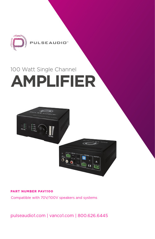
100 Watt Single Channel AMPLIFIERPART NUMBER PAV1100 Compatible with 70V/100V speakers and systems | | 800.626.6445CMRR .....................................................................<70dB@20Hz~20kHzSNR .........................................................................69.2db (Max)Bandwidth ...........................................................20Hz~20kHzRated Power Output ........................................100 WattTHD + Noise ........................................................1%@1kHz, 0.3%@20kHz at nominal levelVoltage Gain .......................................................37.8dBRS-232 Control...................................................(1) 3-pole 3.81mm captive screw connectorFront Panel Control ..........................................ButtonsID Code Control .................................................16 ID codes for controlOptional ................................................................PAV140-IR remote and IR receiver sold separately)T emperature ........................................................-10~ +40 degrees CelsiusHumidity ...............................................................-10% ~ 90%Power Supply .....................................................DC 24V 5A Power AdapterStandby Power Consumption ......................5WDimensions ..........................................................5.11” W x 2.5” H x 5.9” DWeight ...................................................................3.17 lbs4PANEL DESCRIPTIONSFRONT PANEL23411. Input Selection Button (sequential order)• 1 – Analog RCA• 2 – Analog 3.5mm/Aux• 3 – Digital T oslink2. EQ Selection Button (sequential order)3. Rotary Settings Dial to control volume, bass, treble, etc. levels• Set EQ Selection to the desired setting to adjust level4. Volume/Level control (can be PUSHED to MUTE and UNMUTE audio)561.Power Indicator: Red LED emits when powered on2. Microphone Input Port: 3-pole captive crew connector for microphoneinput, toggle switch to select 48V (for condenser microphone), MIC (for dynamic microphone) and LINE (for line audio)3. 3.5mm Analog Audio Input: 3.5mm for stereo audio input4. ID Code: 16 codes range from 0 to F (hexadecimal), works together withthe included PC control software, can also download from on the product page under “downloads”5. IR Input: Part # PAV140-IR is needed (sold separately), to control thePAV1100 via IR; this allows the PAV1100 to be hidden or enclosed while still controlling the unit via IR remote6. Power Port: Connect the included power adapter (DC24V)7. RCA Analog Audio Input: RCA for stereo audio input8. T oslink Digital Audio Input: T oslink/SPDIF for digital audio input9. RS-232: For 3rd party control, see “RS232” section of manual, commandsand protocol are also available on , under “downloads”; 3-pole captive screw connector for serial control, can be connected with PC (Use a 3-pole captive to 9 pin female D connector and serial control software)10. Audio Output: Connect to 70V or 100V speakers; COM is for ground(GND)16234578910CONNECT AND OPERATE1. Ensure PAV1100 amplifier is powered off2. Connect an analog (3.5MM stereo or RCA) and/or digital (optical) audio cablebetween the audio output of the source device and the appropriate audio input 3. IF USING A MICROPHONE: Move the Mic Input Switch to the appropriate settingand connect using the 3 conductor phoenix connecter based on the type ofmicrophone being used• 48V – 48dB gain with 48V phantom power: When the switch turns to “48V” (for high frequency characteristic, high input impedance and high sensitivity in thismode), the MIC input will provide a 48V phantom power. This is usually used for power supply for condenser microphone, Connection is: “+” connects to positive, “-”connects to negative and “ ” to ground. (Note: In this mode, only condenser microphone can be connected)• MIC – 48dB gain: When the switch turns to “MIC” (for low frequency characteristics, and wide frequency response in this mode). The microphone input is used forconnecting a dynamic microphone. There are two different connections: Unbalanced connection:“+” and “ ” connect to ground, and “-” connects to signalor“-” and “ ” connect to ground, and “+” connects to signalBalanced connection:“+” connects to positive, “-” connects to negative and “ ” connects to groundLINE – 4dB gain: When the switch turns to “LINE” (for low frequency characteristics, and wide frequency response in this mode), the microphone input is used for connecting with normal audio or wireless microphone output. There are two different connections: Unbalanced connection:“+” and “ ” connect to ground, and “-” connects to signalor“-” and “ ” connect to ground, and “+” connects to signalBalanced connection:“+” connects to positive, “-” connects to negative and “ ” connects to ground84. Connect the speakers according to the following diagram:5. OPTIONAL: If using IR with the PAV140-IR (sold separately), connect the IR receiver into the IR IN port of the PAV11006. OPTIONAL: If using RS-232, connect the provided 3-conducter phoenix connector cable into the RS-232 port• By default, the RS-232 ID selector is set to 0• Setting the ID selector to any of the other values will prevent the PAV1100 from accepting any RS-232 commands in the incorrect format• NOTE: For additional documentation, please visit the product page at www.vanco1.com under “downloads”7. Connect the power supple into the power input port8. Power on attached audio devices and test9NOTICE1. The letter inside bracket [ ] is the variable code, which is able to be changed2. The bracket [ ] is not included to the actual RS232 commands3. Any dot “.” after the letters is part of the commands4. ID coding:• The ID codes of 100 Watt Power Amplifier ranges from 0 to F (hexadecimal), when sending RS232 commands, please take notice of the address of the ID code• If the address of the ID code is 0, any RS232 command is available• If the address is in 1~F, it has one unique ID code (If the ID code is not the same with the address, no RS232 command will work)• While the ID code is in 1~F, please add “ID/” before sending the command• For example, if the ID code is 5, the RS232 command needed is “604%”, the correct command is in this format: 5/604%• There is no need to add “ID/” before the command when the ID code is 0Examples:1. Switching the input 2 to the line out, the command is: 2A1.2. Turning up the volume of line audio, the command is: 603%3. Preset the MIC volume to “21” degree, the command is: 521%4. Checking the working status of 40 Watt Power Amplifier, the command is: 600%5. If the ID code is 0, sending command 601% is able to turn up the MIC volume. If the IDcode is 2, sending command 601% will not work, and the MIC volume remains unchanged. The right command is 2/601%.Ducking FunctionThis feature is ENABLED by default but can be disabled via RS232 by sending the command “610%”. When an input is selected with MIC, the volume of the line audio will be automatically turned down to the preset volume level. You can set this level via RS232 by sending the command “5[ ][ ]%”. If there is no input MIC audio signal after several seconds, then the volume will be automatically turned up to the original level.1112TECHNICAL SUPPORTIn case of problems, please contact Vanco T echnical Support by dialing1-800-626-6445. You can also email technical support issues to techsupport@ . When calling, please have the Model Number, Serial Number (affixed to the bottom of the unit) and Invoice available for reference duringthe call. Please read this Instruction Manual prior to calling or installing this unit, since it will familiarize you with the capabilities of this product and its proper installation. All active electronic products are 100% inspected andtested to insure highest product quality and trouble-free installation and operation. The testing process utilizes the types of high-definition sources and displays typically installed for entertainment and home theatre applications.For additional information please visit .SAFETY AND NOTICEThe PAV1100 has been tested for conformance to safety regulations and requirements, and has been certified for international use. However, like all electronic equipment, the PAV1100 should be used with care. Please read and follow the safety instructions to protect yourself from possible injury and to minimize the risk of damage to the unit.• Follow all instructions and warnings marked on this unit.• Do not attempt to service this unit yourself, except where explained in thismanual.• Provide proper ventilation and air circulation and do not use near water.• Keep objects that might damage the device and assure that the placement of thisunit is on a stable surface.• Use only the power adapter and power cords and connection cables designed forthis unit.• Do not use liquid or aerosol cleaners to clean this unit.• Always unplug the power to the device before cleaning13to Vanco. A surge protector, power conditioner unit, or an uninterruptible power supply must be installed in the electrical circuit to protect against power surges. If repairs are needed during the warranty period the purchaser will be required to provide a sales receipt/sales invoice or other acceptable proof of purchase to the seller of this equipment. The seller will then contact Vanco regarding warranty repair or replacement.14LIABILITY STATEMENTEvery effort has been made to ensure that this product is free of defects. The manufacturer of this product cannot be held liable for the use of this hardware or any direct or indirect consequential damages arising from its use. It isthe responsibility of the user and installer of the hardware to check that it is suitable for their requirements and that it is installed correctly. All rights are reserved. No parts of this manual may be reproduced or transmitted by any form or means electronic or mechanical, including photocopying, recordingor by any information storage or retrieval system without the written consent of the publisher. Manufacturer reserves the right to revise any of its hardware and software following its policy to modify and/or improve its products where necessary or desirable. This statement does not affect the legal rights of the user in any way.15。
Ashly FX系列DSP功能强大的音频放大器说明书

FX 500 Front PanelFX 60 and FX 125 Front PanelThe FX series is a range of multi-purpose installationDSP-equipped amplifiers. The FX series amplifiers feature a built-in Wireless-Access-Point (WAP) for simple connection and configuration via WiFi as a well as an intuitive web-based software UI. With 6 models to choose from starting at 2 x 60W in a half rack unit to 4 x 500W in a two rack unit, there’s an FX that will fit just about any project.Naturally, they have the rugged reliability that Ashly is known for…including a 5-year warranty.TECHNICALSPECSonPAGE FOURFX SeriesDSP Power A mplifiers with intuitive web-based software UI and built-in WiFi for convenient connectivity and configuration.❚Conference/Huddle Rooms ❚Classrooms ❚Retail Stores ❚Hotel Lobbies❚Inside Displays & Kiosks ❚Bars and Restaurants ❚Trade Show Exhibits ❚HoW & AuditoriumsFX 60 and FX 125 Front PanelFX 500 Front PanelFX 500.2 – Back FX 500.4 – Back – Amplifier operational.– Standby Mode.– GPIO triggered Standby Mode– No input signal present.– Signal present on one or more inputs.– Signal limiting/clipping on one or more inputs.Off – No output signal present.Green – Signal present on one or more outputs.Amber – Signal limiting/clipping on one or more outputs.Red – One or more channel pair is in overload/protection mode.4-Channel Models– WiFi disabled. – WiFi enabled– No Ethernet network detected. – Network enabled– Ethernet network detected.AnalogAnalog AC receptacle100-240VAC 50/60HzInput/Output 2-Channel ModelsEach FX model offers a healthy compliment of IO (include Digital SPDIF In & Out) and programmable integration ports for remote Volume Control, GP triggers and more.FX is networkable via Ethernet for wired LAN connection, or via its built-in WiFi hotspot. FX allows system configurations that don’t require additional equipment, such as stand-alone DSP or speaker system processors. All of that is in one box.Page 3 of 4FX SeriesHigh-Density DSP Power AmplifiersIntelligent DSPTo control FX’s powerful DSP, you’ll find easy access to its intuitive and user-friendly interface via a simple web browser (similar to AquaControl). No software to install (it’s built into the FX unit).Just connect using the Ethernet port or built-in WiFi and you’re ready to Rock & Roll. The WiFi connection allows secure ID and password protection from unauthorized use and for more advanced users, Ethernet allows custom IP settings for use on a more complex wired LAN.The FX Series features a powerful DSP engine that canconfigure to suit virtually any task, without the need for additional equipment. From processing input sources, routing and output DSP that can fine tune the sound of any speaker. Everything you need is right there. These will mixinto Zones A-D and then into Outputs (2 or 4 depending on the number of amplifier channels). All models have a 4-channel DSP configuration with Input processing, Zone Processing, Output Processing, Speaker Processing and Device SettingsAnalog 3Analog 2Analog 1Analog 4SPDIF (stereo)Input Setupgn i t u o R & p u t e S e n o Z Output SetupOutput 1Output 2Output 3Output 4sr e t e m a r a P t n e m t s u j d A m o o R sr e t e m a r a P t n e m t s u j d A r e k a e p S Four-Channel models onlyIntuitive Software UIBrowser-based control from any deviceFA1.2RPM – 1 or 2-amp rack-mount kitFA2.2RPM – Rear rack support kitAshly Audio, Inc. • 847 Holt Road • Webster, NYUSA • US toll-free +1.585.872.0010 Fax +1.585.872.0739•***************©2019-2022 Ashly Audio A Division of JAM Industries USA, LLC. All Rights Reserved. Ashly is a registered trademark. Any other trademarks are property of their respective holders.All Specifications are subject to change.FX_DS_v01.1FX SERIES ARCHITECT & ENGINEERING SPECIFICATIONSin .txt format are available in the DOWNLOADS section of FX SERIES2D AUTOCAD FILES are available in the DOWNLOADS section of https://bit.ly/3ppPEvUDownload the full FX User Manual at https://bit.ly/3GL73FdUSER MANUALOptional Rack Mounts (For half rack models)1) N ote:*100V line mode operates @ -1 dB (≈ 90 V)**FX125.4 and FX 500.4 may only Powershare across Ch1/2 and Ch3/4 Country Of Origin (COO): FX60.x and 125.x is China and FX 500.x is Thailand。
- 1、下载文档前请自行甄别文档内容的完整性,平台不提供额外的编辑、内容补充、找答案等附加服务。
- 2、"仅部分预览"的文档,不可在线预览部分如存在完整性等问题,可反馈申请退款(可完整预览的文档不适用该条件!)。
- 3、如文档侵犯您的权益,请联系客服反馈,我们会尽快为您处理(人工客服工作时间:9:00-18:30)。
1DSP 数字前级放大器AS-V1整机特点:■ 高质量的数字效果器,尽显专业水平;■ 音乐信号激励,增强音乐的动感,更有身临其境的感觉; ■ 话筒输入三段均衡,中频扫描; ■ 全平衡话筒输入,抗干扰能力更强; ■ 话筒音色调整;■ 重低音输出,并带扫频功能; ■ 多功能遥控,可外接专用功能控制器。
前面板控制:1.话筒输入插口MIC ,MIC2,MIC3为全平衡6.3mm 标准输入插口。
2.话筒输入增益控制调节对应的电位器,可分别控制MIC1,MIC2,MIC3的输入增益。
3.话筒EQ低频音调:调节该电位器,可改变话筒低频的提升/衰减量,变化量为±15dB 。
中频音调:调节该电位器,可改变话筒中频的提升/衰减量,变化量为±15dB 。
中频扫描:调节该电位器,可改变中频扫描的频率,频率范围250HZ-6KHZ 。
高频音调:调节该电位器,可改变话筒高频的提升/衰减量,变化量为±15dB 。
4.低通滤波器(DSP )显示部分低通滤波器频率范围为8KHZ~18KHZ 连续可调。
5,12. DSP 效果上下滚动按键 内含55种常用OK 效果 6.变调处理按下对应的开关,可对音乐信号进行降调,原调,升调处理。
7. 主音量声象控制:调节该电位器,可将信号以不同量分配到左、右声道上。
主音量高频音调:调节该电位器,可改变主音量高频的提升/衰减量,变化量为±15dB 。
主音量低频音调:调节该电位器,可改变主音量低频的提升/衰减量,变化量为±15dB 。
8.MIC 输出音量控制调节该电位器,可改变话筒输出信号大小。
9.DSP 效果输出音量控制调节该电位器,可改变DSP 效果输出信号大小。
10.主音量输出控制调节该电位器,可改变主音量输出信号大小。
11.电源开关压下电源开关,电源指示灯“ON”点亮,整机进入工作状态。
后面板控制:1.电源输入与市电进行连接,为整机提供电源,请注意市电是否与本机的工作电源相符。
2.音频信号激励开关按下开关,音乐信号激励,增强音乐的动感,更有身临其境的感觉。
3.数据输出端口通过该端口与我厂提供的专用外置键盘进行连接,可实现有线操作功能。
4,9.重低音输出可通过功放接低音炮。
(两种不同的输出接口)5,6,10.立体声总输出与后段的功放连接,进行功率放大,推动扬声器单元。
(两种不同的输出接口)7.重低音调节调节该电位器,可改变重低音输出的大小和它的频率范围8.立体声输出调节调节该电位器,可改变立体声输出的大小11,13,14.立体声音频信号输入两种不同的输入接口。
12.立体声输入限幅调节调节该电位器,可改变立体声输入信号的大小摇控器功能:1.常用DSP效果六种常用DSP效果:标准1,标准2,柔情,优郁,豪壮和摇滚2.变调处理按下对应的按键,可对音乐信号进行降调,原调,升调处理。
3.话筒信号,效果信号和音频信号调节按下对应的按键,可分别调节话筒信号,效果信号和音频信号的大小4.话筒信号,效果信号和音频信号齐调按下对应的按键,可同时调节话筒信号,效果信号和音频信号的大小5.DSP效果上下滚动按键内含55种常用OK效果AS-V1主要技术参数信号输入3路话筒、立体声音频信号输出2路立体声、1路单声道重低音信噪比﹥90 dB输入灵敏度话筒:-45 dB 线路:0 dB失真(THD)﹤0.1%输入阻抗话筒:单端10KΩ,双端20 KΩ线路:10 KΩ频响范围20HZ-20KHZ ±1.5dB音乐均衡低频100HZ/±15dB 高频10KHZ/±15dB话筒均衡低频100HZ/±15dB 中频250HZ—6KHZ/±15dB 高频10KHZ/±15dB 功耗5W电源AC220V 50 HZ2机箱尺寸482×254×44mm(1U标准机箱)DSP数字前级放大器AS-G1整机特点:音乐处理■多种预置音乐模式,用户可自设保存9种EQ模式■9段图示均衡■数字高、低音控制■立体声数字键控(变调)■cen中置输出■Subwoofer超低音输出■4路音、视频自动输入选择,输入电平匹配调整■BGM背景音频自动切换■音乐电平智能压限(可解决VOD输出信号忽大忽小的问题)麦克风处理■3个独立的音量控制■9段图示均衡■可自设保存9种EQ模式■8种效果模式(各项参数均可调)综合处理■高性能DSP处理■红外线无线遥控■参数记忆功能■RS232输入接口,可用电脑控制■S端子线路遥控接口前面板控制:1.POWER ON/OFF:电源开关;2.STORE/LIMITER:麦克风与音乐均衡用户存储菜单选择;音乐输入限幅菜单选择;3.L/R / THRESHOLD:音乐左右声道选择;麦克风与音乐输入电平阀值设置;4.PROGRAML/RESET:麦克风与音乐的效果参数菜单选择;恢复出厂设置选择;5.FLAT/USER:音乐用户EQ与直通选择;6.GEQ:麦克风与音乐的均衡参数菜单选择;7.MASTER:麦克风与音乐的各参数菜单选择;8.EDITB:音乐效果参数调整旋钮;9.EDITA:麦克风效果参数调整旋钮;10.MIC INPUT:3路Ø6.35mm麦克风输入插座;11.MIC VOL:3路麦克风音量调整旋钮;12.DISPLAY WINDOW:音乐自动选择显示、音乐与麦克风工作状态显示;13.LCD:音乐与麦克风各项参数调整显示;后板:1.电源输入与市电进行连接,为整机提供电源,请注意市电是否与本机的工作电源相符;2.输入电压选择开关拔动此开关,可选择110V的电压和220V的电压,请根据本地的市电进行选择;33.PC CONTROL外接电脑控制输入接口此接口用来连接外部电脑控制;4.REMOTE摇控数据输入端口通过该端口可实现有线操作功能;5.L OUT右声道音频综合输出(XLR)插座1脚:信号地2脚:信号—3脚:信号+;6.R OUT左声道音频综合输出(XLR)插座1脚:信号地2脚:信号—3脚:信号+;7.SUB OUT超低音音频输出(XLR)插座1脚:信号地2脚:信号—3脚:信号+;8.CEN OUT中置音频输出(XLR)插座1脚:信号地2脚:信号—3脚:信号+;9.LEVEL(SUB SET)超低音音量调节旋钮11.CEN LEV中置音量调节旋钮通过调节该电位器可以调整中置音量的大小;12.PRE OUT 立体声音频综合输出(RC)插座此插座可用来作为录音信号音源的输入;13.背景(BGM)音乐输入限幅调节旋钮通过调节该电位器可以调整背景信号音量的大小;14.四组音频信号输入(RC)插座VOD、DVD、AUX、BGM四组信号输入座,当前面三组无信号时,系统会直接回到BGM输入;通过调节该电位器可以调整超低音输出音量大小;10.FREQ(SUB SET)超低音频率调节旋钮通过调节该电位器可以调整超低音输出频率;15.VIDEO OUT视频信号输出(RC)插座16.四组视频信号输入(RC)插座VOD、DVD、AUX、BGM四组视频信号输入座;17.MIC INPUT 麦克风MIC4/MIC5输入插座功能键操作简介A:MASTER按“MASTER”默认进入音乐(music)音量参数调节菜单:按music push(EDIT B )键依次选择如下:Music Master vol:音乐输出的总音量;Sub Master vol:超低音输出音量;Cen Master vol:中置音输出音量;Music Treble vol:音乐高音提升与衰减;Music Bass vol:音乐低音提升与衰减;在Master(music) 各选项下,旋转music Push(EDIT B)依次调节对应的音乐部分的参数值。
MUS MASTER-VOL-5dB按mic push(EDIT A )键依次选择如下:MIC Master vol:麦克风输出总音量;Mic Effect vol:效果音量;Mic Effect Echo:廽响效果音量;Mic Effect Rev:混响效果音量;Mic Echo Delay:廻响延迟时间调整;Mic Echo Repeat: 廻响重复调整;Mic Band Width: 麦克风效果频宽调整;在Master(Mic)各选项下,旋转mic push(EDIT A) 依次调节对应的麦克风部分的参数。
MIC MASTER-VOL-5dBB:GEQ按“GEQ”默认进入音乐均衡调节菜单:按 music push(EDIT B) 键,依次选择均衡频率,旋转music param(EDITB)调整音乐GEQ对应频率的(GAIN)增益。
MUSIC GEQ GAIN63HZ→+ 1dB MUSIC GEQ 主菜单按mic push(EDIT A)键,依次选择均衡频率,旋转mic param(EDIT A)调整麦克风GEQ对应频率的(GAIN)选项。
MIC GEQ GAIN463HZ→ + 1dB MIC GEQ 主菜单C:FLAT/USER按FLAT/USER键,音乐输出平直,同时,在主菜单的显示:再次按FLAT/USER键,音乐直通功能闭,回到用户最后所设置的EQ值,主菜单的显示:D:PROGRAM(程序)按“PROGRAM”键,默认进入music程式菜单:按music push(EDIT B)依次选择:Stereo pitch:音乐立体声变调,共有10级变调;Init Music Vol:音乐音量主输出开机初始设置;Init Sub Vol: 超低音音量开机初始设置;Init Center Vol: 中置音量开机初始设置;Music preset EQ:音乐预设均衡,共有6种均衡;Music Custom EQ:音乐用户存储的均衡,共9种。
旋转music push(EDIT B)对其参数进行设定;按mic push(EDIT A)依次选择:Init Mic Vol: 麦克风音量开机初始设置;Mic Preset EFF: 麦克风预设效果,共有8种;Mic Custom EQ:麦克风用户存储的均衡,共9种;旋转mic push(EDIT A对其参数进行设定E:RESET(恢复出厂设置)长时间按“PROGRAM”键,进入系统参数复位菜单,如下图,根据屏幕提示,分别按music push(EDIT B)或mic push (EDIT A)对音乐和麦克风的所有参数复位到出厂设定。
SYSTEM RESETMUSIC OR MIC ? RESET 主菜单F:L/R按“L/R”键,此时旋转music push(EDIT B)可选择输入音源L声道或R声道,共有4种方式。
