REC-V2 技术文档说明书
Tecnomatrix CAPTOR-S V2 数据采集系统说明书

...réduisant vos frais de 70%?Tecnomatrix, spécialiste dans l’étude et la fabrication de moyens de contrôle a décidé de commencer à développer de nouveaux systèmes de mesure permettant d’investir plus de temps dans l’interprétation des résultats que dans la prise de mesure. CAPTOR-S V2 est notre deuxième génération de systèmes d’acquisition de données. Il s'ag it d'un système facilitant la prise de mesure et pouvant être utilisé sur des moyens de contrôle existants, quel que soit leur fabricant, à la seule condition qu’ils disposent de puits de jaug epour comparateur.DATAEXPORTUn émetteur Bluetooth envoie la valeur mesurée par lecomparateur au PDA ou au PC.Les données sont exportéesaux formats Excel/Q-DasCommunication multipleillimitée et sans fil BluetoothDescriptionAvantagesNotre système se compose d’une unité Bluetooth adaptée sur un com-parateur. Grâce à son système de connexion sans fil, cette unité se connecte à un PDA ou à un PC équipé du logiciel CAPTOR-S V2 et lui envoie la valeur mesurée. La valeur est enregistrée avec la date et l’heure de la mesure, ainsi que le nom de l’utilisateur. Le Cpk de la série de pièces mesurée est calculé automatiquement à partir de 10 pièces mesurées. Les données enregistrées peuvent être exportées à un PC en format Excel/Q-Das au moyen de fichiers d’exportation configurables.• Gain de temps : Plus de mesures en moins de temps.• Fiabilité: Evite les erreurs de transcription.• Traçabilité: Qui mesure, avec quel comparateur et quel moyen de contrôle, et quand (date et heure).• Flexibilité: Peut être configuré sur vos autres moyens de contrôle disposant de puits de jauge.• Automatisation: Grâce à des fichiers d’exportation configurables, les données enregistrées peuvent être exportées à un PC en format Excel/Q-Das dans l’ordre souhaité, aussi bien en lignes qu’en colonnes.• Moins de modifications de vos moyens de contrôle: Grâce au facteur de correction de chaque point, vous gagnerez du temps et de l’argent.* P a t e n t p e n d i n gDescriptionAvantagesCAPTOR-S V2 PRO est une extension du logiciel disposant de deux fonctions supplémentaires:• Activation à distance d’un ou de plusieurs comparateurs : possibilité d’activer le comparateur depuis le PDA/PC.• Mesure en continu pendant une période de temps définie. Exemple : mesure durant un intervalle de 10 sec. toutes les 0,4 sec. • Mesure de composants cylindriques, de cames et d’axes pour calculer leur erreur de forme.• Mesure de zones difficiles d’accès , ou sans accès.• Activation automatique de plusieurs comparateurs CAPTOR-S.• L’activation à distance évite des déviations causées par de faux mouvements .Logiciel V2 PRO[+ info]Pol. Ind. La Serra 1 C/ Bergada 3, nave 2 08185 Lliçá de Vall Barcelone (Espagne)t. +34 93 843 64 30f. +34 93 843 61 76***************************Consultez également:。
RE22R2AMR产品数据手册说明书

RE22R2AMR.T h e i n f o r m a t i o n p r o v i d e d i n t h i s d o c u m e n t a t i o n c o n t a i n s g e n e r a l d e s c r i p t i o n s a n d /o r t e c h n i c a l c h a r a c t e r i s t i c s o f t h e p e r f o r m a n c e o f t h e p r o d u c t s c o n t a i n e d h e r e i n .T h i s d o c u m e n t a t i o n i s n o t i n t e n d e d a s a s u b s t i t u t e f o r a n d i s n o t t o b e u s e d f o r d e t e r m i n i n g s u i t a b i l i t y o r r e l i a b i l i t y o f t h e s e p r o d u c t s f o r s p e c i f i c u s e r a p p l i c a t i o n s .I t i s t h e d u t y o f a n y s u c h u s e r o r i n t e g r a t o r t o p e r f o r m t h e a p p r o p r i a t e a n d c o m p l e t e r i s k a n a l y s i s , e v a l u a t i o n a n d t e s t i n g o f t h e p r o d u c t s w i t h r e s p e c t t o t h e r e l e v a n t s p e c i f i c a p p l i c a t i o n o r u s e t h e r e o f .N e i t h e r S c h n e i d e r E l e c t r i c I n d u s t r i e s S A S n o r a n y o f i t s a f f i l i a t e s o r s u b s i d i a r i e s s h a l l b e r e s p o n s i b l e o r l i a b l e f o r m i s u s e o f t h e i n f o r m a t i o n c o n t a i n e d h e r e i n .Product data sheetCharacteristicsRE22R2AMROn-delay Timing Relay - 0.05s…300h - 24…240V AC/DC - 2C/OMainRange of product Zelio TimeProduct or component typeModular timing relay Discrete output type Relay Device short name RE22Nominal output current8 AComplementaryContacts type and composition 1 C/O timed or instantaneous contact, cadmium free 1 C/O timed contact, cadmium free Time delay type A AwTime delay range0.3...3 s 1...10 s 0.05...1 s 3...30 s 10...100 s 30...300 s 3...30 min 30...300 min 3...30 h 30...300 hControl typeExternal potentiometer Diagnostic button Rotary knob[Us] rated supply voltage 24...240 V AC/DC at 50/60 Hz Release input voltage <= 2.4 V Voltage range 0.85...1.1 Us Supply frequency 50...60 Hz (+/- 5 %)Connections - terminalsScrew terminals : 2 x 0.2...2 x 1.5 mm², AWG 24...AWG 16 flexible cable with ca-ble endScrew terminals : 1 x 0.2...1 x 2.5 mm², AWG 24...AWG 14 flexible cable with ca-ble endScrew terminals : 2 x 0.5...2 x 2.5 mm², AWG 20...AWG 14 solid cable without cable endScrew terminals : 1 x 0.5...1 x 3.3 mm², AWG 20...AWG 12 solid cable without cable endTightening torque 0.6...1 N.m conforming to IEC 60947-1Housing material Self-extinguishingRepeat accuracy +/- 0.5 % conforming to IEC 61812-1Temperature drift +/- 0.05 %/°C Voltage drift+/- 0.2 %/VSetting accuracy of time delay +/- 10 % of full scale at 25 °C conforming to IEC 61812-1Control signal pulse width 30 ms100 ms (with load in parallel)Insulation resistance 100 MOhm at 500 V DC conforming to IEC 60664-1Recovery time120 ms (on de-energisation)Immunity to microbreaks <= 10 ms Power consumption in VA3 VA at 240 V ACPower consumption in W 1.5 W at 240 V DCSwitching capacity in VA2000 VAMinimum switching current10 mA 5 V DCMaximum switching current8 AMaximum switching voltage250 V ACElectrical durability100000 cycles for 2 A at 24 V DC-1100000 cycles for 8 A at 250 V AC-1Mechanical durability10000000 cyclesRated impulse withstand voltage 5 kV for 1.2...50 µs conforming to IEC 60664-1Power on delay< 100 msCreepage distance 4 kV/3 conforming to IEC 60664-1Overvoltage category III conforming to IEC 60664-1Mounting position Any positionMounting support35 mm DIN rail conforming to EN/IEC 60715Status LED Yellow LED (slow flashing) for timing in progress and output relay energisedYellow LED (fast flashing) for timing in progress and output relay de-energisedYellow LED (steady) for output relay energisedGreen LED backlight (steady) for dial pointer indicationProduct weight0.105 kgEnvironmentDielectric strength 2.5 kV for 1 mA/1 minute at 50 Hz between relay output and power supply withbasic insulation conforming to IEC 61812-1Standards IEC 61812-1UL 508Directives2004/108/EC - electromagnetic compatibility2006/95/EC - low voltage directiveProduct certifications CCCCECSAGLULRCMEACChina RoHSAmbient air temperature for operation-20...60 °CAmbient air temperature for storage-40...70 °CIP degree of protection IP50 (front panel) conforming to IEC 60529IP20 (terminals) conforming to IEC 60529IP40 (housing) conforming to IEC 60529Pollution degree 3 conforming to IEC 60664-1Vibration resistance20 m/s² (f = 10...150 Hz) conforming to IEC 60068-2-6Shock resistance 5 gn (in operation) (duration = 11 ms) conforming to IEC 60068-2-2715 gn (not operating) (duration = 11 ms) conforming to IEC 60068-2-27 Relative humidity95 % at 25...55 °CElectromagnetic compatibility Immunity to microbreaks and voltage drops (test level: 100 % - 20 ms) conform-ing to IEC 61000-4-11Immunity to microbreaks and voltage drops (test level: 30 % - 500 ms) conform-ing to IEC 61000-4-11Fast transient bursts (test level: 2 kV, level 3 - direct contact) conforming to IEC61000-4-4Conducted RF disturbances (test level: 10 V, level 3 - 0.15...80 MHz) conformingto IEC 61000-4-6Radiated radio-frequency electromagnetic field immunity test (test level: 10 V/m,level 3 - 80 MHz...1 GHz) conforming to IEC 61000-4-3Electrostatic discharge (test level: 8 kV, level 3 - air discharge) conforming to IEC61000-4-2Electrostatic discharge (test level: 6 kV, level 3 - contact discharge) conforming toIEC 61000-4-2Surge immunity test (test level: 2 kV, level 3 - common mode) conforming to IEC61000-4-5Surge immunity test (test level: 1 kV, level 3 - differential mode) conforming toIEC 61000-4-5Fast transients immunity test (test level: 1 kV, level 3 - capacitive connecting clip)conforming to IEC 61000-4-4Product data sheetRE22R2AMR Dimensions DrawingsDimensionsProduct data sheetRE22R2AMR Connections and SchemaWiring DiagramProduct data sheetRE22R2AMRTechnical DescriptionFunction A: Power On-DelayDescriptionOn energisation of power supply, the timing period T starts. After timing, the output(s) R close(s).The second output (R2) can be either timed (when set to "TIMED") or instantaneous (when set to "INST").Function: 1 OutputFunction: 2 OutputsFunction Aw : Power On-Delay With Retrigger / Restart ControlDescriptionOn energisation of power supply, the timing period T starts.At the end of the timing period T, the output(s) R close(s).Energization of Y1 makes the output(s) R open(s).Deenergization of Y1 restarts timing period T.At the end of timing period T, the output(s) R close(s).The second output (R2) can be either timed (when set to "TIMED") or instantaneous (when set to "INST")Function: 1 OutputFunction: 2 OutputsLegendRelay de-energisedRelay energisedOutput openOutput closedUSupply-TTiming period-R1/2 timed outputsR2-R2The second output is instantaneous if the right position is selected inst.-Retrigger / Restart controlY1-RE22R2AMR.。
大唐移动v2系统试验指导书附带详细操作说明 (1)

目录目录 (1)第一单元:设备硬件观察 (2)实验一:教学装备硬件观察实验 (2)第二单元:设备开通与配置实验 (3)实验一、CN2000开通 (3)实验二、OMC安装调试 (3)实验三、RNC数据备份、恢复、同步 (4)实验四、N ODE B本地软固件升级 (5)实验五、基站典型网元布配 (6)实验六:GPS时钟的连接与查询 (7)实验七:基站板卡的状态查询 (8)第三单元:网管操作实验 (9)实验一:OMT上创建基站、小区 (9)实验二、小区激活与传输状态 (10)第四单元:业务算法与信令实验 (11)实验一:CS/PS/视频业务实验 (11)第一单元:设备硬件观察实验一:教学装备硬件观察实验一、试验目的1.初步了解嵌入式通信设备组成2.认知大唐移动模拟核心网、OMC、RNC、基站设备的基本结构3.初步分析硬件功能设计二、试验内容1.观察核心网、OMC、RNC、基站、RRU,关注各网元整体状态、在系统中的位置、各网元板卡配置位置、接口、以及网元之间连接方式、供电方式,并以正确的方式插拔板卡。
三、试验仪器四、试验步骤1.断开装备总电源,确认各网元电源状态为关闭。
2.佩戴防静电手环,逐个观察CN、OMC、RNC、NodeB、RRU,以正确方式拔出网线或光纤,记录接口连接位置;以正确方式拆下板卡,记录板卡位置和各接口。
3.把网线或光纤插回正确的接口,把板卡插回正确的槽位。
五、试验报告要求1.画出教学装备网元连接示意图,包括各网元名称、网元内部板卡及接口。
第二单元:设备开通与配置实验实验一、CN2000开通一、实验目的1.认知CN2000软件功能2.掌握CN2000安装方式3.掌握CN2000参数配置二、实验内容1.CN2000软件安装;2.CN2000参数配置:PS业务MAC地址配置、FTP服务器IP配置、SIM卡信息添加。
三、试验仪器RAN系统(RNC、NB、RRU、OMC)1套CN2000 1PC 1四、实验报告要求1.写出MAC地址对应设备名称;2.写出CN2000参数配置内所有IP地址对应功能;实验二、OMC安装调试一、实验目的1.认知OMC软件功能;2.认知OMC内部各软件系统组成,及各参数配置;3.掌握OMC安装方法;4.了解OMC启动过程;二、实验内容1.以正确顺序安装OMC内部各软件系统;2.启动OMC,成功创建O链路;三、试验仪器RAN系统(RNC、NB、RRU、OMC)1套OMT 1PC 1三、实验报告要求1.写出OMC内部个软件系统启动顺序;2.查询O链路状态,并截图。
二次开发技术文档
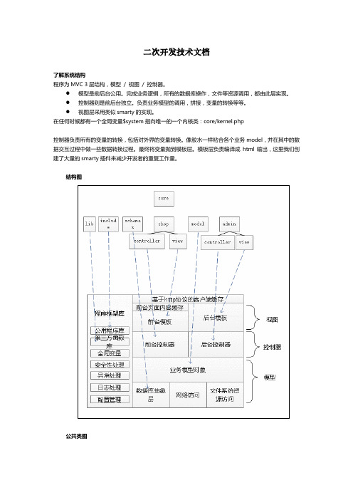
二次开发技术文档了解系统结构程序为MVC 3层结构,模型/ 视图/ 控制器。
●模型是前后台公用。
完成业务逻辑,所有的数据库操作,文件等资源调用,都由此层实现。
●控制器则是前后台独立。
负责业务模型的调用,拼接,变量的转换等等。
●视图层采用类似smarty的实现。
在任何时候都有一个全局变量$system指向唯一的一个内核类:core/kernel.php控制器负责所有的变量的转换,包括对外界的变量转换。
像胶水一样粘合各个业务model,并在其中的数据交互过程中做一些数据转换过程。
最终将变量抛到模板层。
模板层负责编译成html输出,这里我们创建了大量的smarty插件来减少开发者的重复工作量。
结构图公共类图公共函数库公共函数库位于/core/func_ext.php,它在内核加载时首先被加载,对全系统有效。
其中包含若干php5函数的php4模拟版本:●file_put_contents●json_encode●json_decode●ftp_chmod●array_diff_key●http_build_query运行过程商派Commerce B2B标准版前后台调度都分别通过各自目录下一个名为index.php的入口文件进行,入口文件接受控制器、方法等的输入参数,调度给对应的控制器方法执行并输出结果。
index.php会调用kernel。
Kernel基础类提供模型对象加载,插件入口,错误处理,设置管理,输入输出,第三方类库加载等基础服务。
前后台及安装入口程序在初始化时,都会初始化一个对应的内核类,这个类在前台是shopCore.php,后台时是adminCore.php。
这两个文件都是继承core/kernel.php文件。
该内核类首先会形成一个名为system的指向自身的全局对象,然后根据传入参数调用对应的控制器方法运行。
控制器层与模型层都会产生对该全局system对象的调用来使用基础服务。
并且控制器和模型层在自身被实例化之后都可以使用$this->system来引用内核对象。
V2手册下载

1.前言为了充分地发挥本变频器的功能及确保使用者的安全请详阅本操作手册当您使用中发现任何疑难而本操作手册无法提供您解答时请联系台安各地区经销商或本公司业务人员我们的专业人员会乐于为您服务并请您继续采用台安产品使用须知变频器是精密的电力电子产品为了您的生命财产安全本手册中有危险注意等字样提醒您在搬运安装使用检查变频器时的安全注意事项请您配合遵守危险操作不当时可能造成严重的人身伤害注意操作不当时可能造成变频器或机械系统损坏危险z在变频器断电后在主板上的红色充电指示灯未熄灭前请勿触摸线路板z不可在送电过程中实施配线变频器处于运行状态时请勿检查线路板z请勿自行拆装更改变频器内部连接线或线路及零件z变频器接地端请务必正确接地200V级接地阻抗<100Ω400V级接地阻抗<10Ω注意z请勿对变频器内部的元件进行耐压测试半导体零件易受高电压击穿损坏z绝不可将变频器输出端子T1(U)T2(V)T3(W) 连接至交流电源z变频器主电路板CMOS集成电路易受静电影响及破坏请勿触摸主电路板2. 产品检查每台台安变频器在出厂前均做过功能测试客户于变频器送达拆封后请执行下列检查步骤z变频器的机种型号是否正确符合您所订购的型号与容量z变频器是否因运送不慎造成损伤若有损坏请勿接入电源当您发现有上述问题时请立即通知台安科技各区业务人员第一章安全注意事项¤@¡B使用时注意事项送电前注意危险主回路端子配线必须正确L1L2L3为电源输入端子绝对不可以与T1T2 T3混用如若混用送电时会将造成变频器损坏注意避免变频器掉落造成人员受伤或变频器损坏z请将变频器安装于金属类等不易燃烧的材料上请不要安装在易燃性材料上或附近以免发生火灾z若多台变频器同放在一个控制柜内请外加散热风扇使箱内温度低于 40以下以防过热或火灾等发生z在变频器完全断电后再拆卸或装入操作面板并请按图操作固定面板以免接触不良造成面板故障或不显示z送电中绝不可插拔变频器上的连接器以避免控制板因带电插拔所产生的浪涌电压造成内部电路损坏z若停电时间大于两秒功率越大可允许断电时间越长变频器会失去供电源在电源恢复送电以后是根据P_05及P_103的设定及外部开关的状态而决定此视为重新开机z若停电时间短变频器仍拥有控制电源因此当电源回复时变频器能否自行启动将取决于P_101/102参数的设定z当重新开机时变频器运转与否取决于P_005及P_103参数设定及电源开关/运转开关FWD/REV开关的状态与P_101/102/104/105无关1.P_005=0时重新开机后不会自动启动2.P_005=1且电源开关或运转开关正转/反转开关关断时重新开机后不会自动启动3.P_005=1电源开关及运转开关导通且P_103=XXX0时重新开机后会自动启动基于安全考虑请在停电以后将电源开关及运转开关关断以避免突然复电后对机器及人身造成伤害z P_103=XXX0时为确保人员及机器设备安全请参照P_103参数的详细使用说明及操作建议运转前危险请确认所使用的机种容量和变频器P_000所设定的机种容量相同注意运转中不可将电机机组投入或切离否则会造成变频器过电流跳机严重时会造成变频器主回路损坏危险z变频器送电状态时请勿取下前盖以防人员触电受伤z若设定自动再启动功能时电机于运转停止后会自动再启动请勿靠近机器以免危险z停止开关的功能须设定才有效与紧急停止开关的用法不同请注意使用注意z散热座制动电阻等发热组件请勿触摸z变频器可以很容易的使电机由低速到高速运转请确认电机与机械的容许范围z使用制动控制器等外接设备时请注意其使用的相关设定z变频器运转状态时请勿检查电路板上的信号注意请先确认电源切断后且充电指示灯LED 101熄灭后方可进行拆装或实施检查检查保养时注意变频器周围温度应在-10~+40 95%RH不结露环境中使用注意去掉变频器外壳后则周围温度应在-10~+50 95%RH不结露环境中使用但需确保周围环境无滴水及金属粉尘G B使用环境的注意事项请避免在以下场所使用变频器日光直射的场所腐蚀性气体及液体的场所有油气的场所有盐分的场所风雨及水滴会侵入的场所铁屑粉尘的场所震动大的场所温度过低场所周围温度过高的场所有电磁波超高波的场所如电焊机等机器的场所放射性物质的场所堆放可燃物的场所油盐第二章 硬件说明及安装一使用环境变频器安装的环境对变频器正常功能的发挥及其使用寿命有直接的影响因此变频器的安装环境必须符合下列条件z周围温度 -10~+40取掉外盖时可适用-10~+50z 防止雨水滴淋或潮湿环境z 避免直接日晒z 防止油雾盐分侵蚀z 防止腐蚀性液体瓦斯z 防止粉尘棉絮及金属细屑侵入z 远离放射性物质及可燃物z 防止电磁干扰熔接机动力机器z 防止震动冲床若无法避免请加装防震垫片以减少震动z多台变频器安装于控制盘内时请注意摆放位置以利散热另请外加配置散热风扇以使变频器周温低于40为原则(正确的安装方式) (错误的安装方式) (正确的安装方式) (错误的安装方式)z 安装时请将变频器正面朝前顶部朝上以利散热z 安装空间必须符合下列规定(若安装于盘内或周围环境许可时可取下变频器之防尘上盖以利变频器散热通风)配电盘内 配电盘内配电盘内换气扇换气扇配电盘内安装方向 通风对流 -10~ + 40(a) 正面(b) 侧面二型号说明型号说明变频器型号→MODEL V2-202-H输入电源规格→I/P AC 1 OR 3PH200~240V 50/60Hz输出规格→O/P AC 3PH 0~240V2.9 KVA 7.5 ATAIAN ELECTRIC CO. LTD.V 2 - 2 05 - H 3系列别规格电源种类电源电压M标准型空白单相/三相共用机种2220V H附PG反馈型1单相机种4440V 3三相机种外型构造马力数空白IP2001 1 马力1010 马力4040马力02 2 马力1515 马力5050马力03 3 马力2020 马力6060马力05 5 马力2525 马力087.5 马力3030 马力三规格产品个别规格单相 / 三相共用200~240V 机种型号V2-□□□-xxx201 202 203 适用电机功率KW0.75 1.5 2.2 适用电机容量HP 1 2 3 额定输出电流A 4.5 7.510.5额定容量KVA1.72.9 4.0 输入电压 单相或三相200~240 ±10%50/60H Z± 5%输出电压 三相 200~240V允许瞬停时间秒1.02.0 2.0三相200~240V 机种型号V2-□□□-xxx205 208 210 215 220 225 230适用电机功率KW 3.7 5.5 7.5 11 15 18.5 22 适用电机容量HP5 7.5 10 15 20 25 30 额定输出电流A 17.5 26.0 3549647687额定容量KVA6.7 9.9 13.3 18.7 24.4 29 33.2输入电压 三相200~240 ±10%50/60Hz ± 5%输出电压 三相 200~240V允许瞬停时间秒2.02.02.02.02.02.02.0三相380~480V 机种型号V2-□□□-xxx 401 402 403 405 408 410 415 420 425 430 440 450 460CT 30 37 45适用电机功率(KW) VT 0.75 1.5 2.2 3.7 5.5 7.5 11 15 18.5 2237 45 55CT 40 50 60适用电机容量(HP) VT 1 2 3 5 7.5 10 15 20 25 3050 60 75CT 65 80 97额定输出电流(A) VT 2.3 3.8 5.2 8.8 13 17.5 25 32 40 4875 91 112CT 49.5 61 73.9额定容量(KVA) VT 1.7 2.9 4.0 6.7 9.9 13.3 19.1 24.4 31 36.657.2 69.4 85.4 输入电压 三相380~480±10% 50/60H Z ± 5%输出电压 三相 380~480V允许瞬停 时间(秒)1.0 1.02.0 2.0 2.0 2.0 2.0 2.0 2.0 2.0 2.0 2.0 2.0产品共通规格项 目规范控 制 方 式 V/F 或 电流向量 (附/不附 PG 反馈卡)控制范 围 V/F0.5~400Hz 向量0.0~电机铭牌频率的3.5倍频率启动转矩 150%/0Hz 不附PG 200%/1Hz速度控制范围 1:1000 (不附PG 1:100) 速度控制精度 ±0.02% (不附PG ±0.2%) 设定分辨率数字式0.01Hz( 注1 )模拟式0.06Hz/ 60Hz面板设定方式 可直接以▲▼设定或以面板上的电位器旋钮设定显示功能四位数七段显示器及状态指示灯; 可显示频率/转速/线速度/直流电压/输出电压/电流/变频器转向/变频器参数/故障记录/程序版本 外部信号 设定方式1. 可外接可变电阻允许0-5V/ 0-10V/ 4-20mA/ 5-0V/ 10-0V/ 20-4mA 信号输入2.端子台(TM2)的多功能接点可作为增/减频率控制段速控制程序段速+时间控制频 率控制频率限制功能 频率上/下限三段跳跃频率可分别设定载波频率 2 ~ 16 kHz加减速控制 3段加减速时间0.1-3600秒及2段S 曲线参考P_021参数说明转矩控制可设定转矩提升准位多功能模拟量输出 有5种功能(参考P_072参数说明) 多功能输入 有23种功能(参考P_052~057参数说明) 多功能输出 有8种功能(参考P_075/076参数说明)一般控制其它功能 自动电压调整AVR 自动转差补偿自动节能运行减速停止或自然停止或旋转停止spin stop 自动复归再启动自动直流制动旋转启动spin start 或一般方式启动 3 线运转控制PID 功能项目V2 TYPE四位数七段显示器及状态指示灯可显示频率/转速/线速度/直流电压/输出电压/电流/变频器转向/变频器参数/故障记录/程序版本通信控制 1.可以RS232或RS485进行通信控制2.可作1对1或1对多仅用于RS485通信控制3.可设定波特率/停止位/奇偶位/校验位/数据位操作温度-10 ~ 40湿度 0–95%相对湿度不结露振动 0.5G以下EMC规格使用滤波器下符合EN 50081-1及50082-2要求LVD规格符合EN 50178的要求保护等级 IP20/NEMA410HP含以下安全等级UL 508C过载保护电子热保护继电器保护电机曲线可设定及变频器(150 % / 1分钟)保险丝熔断保护保险丝熔断后电机停止过电压 200V级直流电压420V 400V级直流电压840V不足电压 200V级直流电压200V 400V级直流电压400V瞬间停电再启动瞬停后时间可设定至2秒可以以旋转启动Spin start方式重新启动失速防止加速/减速/运转中失速防止输出端短路电子线路保护接地故障电子线路保护保护功能其它功能散热片过热保护过转矩侦测故障接点控制反转限制开机后直接启动及故障复归的限制参数锁定注1变频器使用操作面板控制时100Hz以上分辨率为0.1Hz当计算机PC或可编程控制器PLC 与变频器采用通信方式控制时运转在100Hz以上分辨率为0.01Hz注2V2-203以上机种无CE认证注3如需长期运转在3Hz以下请采用向量控制模式四配线规则1.配线应注意事项A.螺丝扭力请依照下列表中所示的螺丝扭力用螺丝起子或其它工具进行配线工作锁固扭力马力数电源规格 TM1端子额定扭力1/ 2/ 3 200-240V1.33 LBS-FT 16 LBS-IN1/ 2 380-480V5/ 7.5/ 10 200-240V1.15 LBS-FT 13.8 LBS-IN3/ 5/ 7.5/ 10 380-480V15/ 20/ 25/ 30 200-240V1.83 LBS-FT 22 LBS-IN15/ 20/ 25/ 30/ 40/ 50/ 60 380-480V注全系列变频器的TM2端子台螺丝扭力都是0.583 LBS-FT或 7LBS-INB.电源线电源线是连接到L1L2L3T1T2T3P R端子的线材电源线的选定必须依下列规定(1)仅能使用铜线线径的选择依摄氏105度为基准(2)线材额定电压的选择240VAC系统最小值为300V480 VAC系统最小值为600VC.控制线控制线为连接到TM2控制端子的线材其选定必须依下列规定(1)仅能使用铜线线径的选择依摄氏105度为基准(2)线材额定电压的选择240VAC系统最小值为300V480 VAC系统最小值为600V(3)控制线不应与动力线电源线电机线在同一导管或保护管中实施配线以避免被噪声干扰D.端子台的电气额定TM1动力端子额定如下表马力数电源规格电压Volts电流Amps1/ 2/ 3 200-240V300 20 1/ 2 380-480V5/ 7.5/ 10 200-240V600 40 3/ 5/ 7.5/ 10 380-480V15/ 20 200-240V600 60 15/ 20/ 25/ 30 380-480V25/ 30 200-240V 600 10040/ 50/ 60 380-480V 600 150注输入及输出讯号(TM2控制端子)的额定等级2配线规定2.保险丝的型式为了能够最有效的保护变频器应该使用有限制电流功能的保险丝建议供货商为Gould ATM, FERRAZ 或其它的制造商可替代的相等规格的零件马力数电源规格 保险丝额定115A, 600VAC, 100KA I.R. 2 15A, 600VAC, 100KA I.R. 3 20A, 600VAC, 100KA I.R. 530A, 600VAC, 100KA I.R. 7.5/ 10 60A, 600VAC, 100KA I.R. 15/ 20 100A, 600VAC, 100KA I.R. 25/ 30 200-240V150A, 600VAC, 100KA I.R. 1 5A, 600VAC, 100KA I.R. 2 10A, 600VAC, 100KA I.R. 3 15A, 600VAC, 100KA I.R. 520A, 600VAC, 100KA I.R. 7.5/ 10 40A, 500VAC, 100KA I.R. 15/ 20 70A, 600VAC, 100KA I.R. 25/ 30/40 100A, 600VAC, 100KA I.R. 50/ 60380-480V150A, 600VAC, 100KA I.R.3.注意事项3.1当电源接通时或电源刚从主机脱离的时候不要触碰任何电路元件以避免发生触电危险必须等待充电显示灯完全熄灭后才能进行其它动作 3.2在变频器的电源没有断电前不要对变频器实施任何配线的动作忽视上述警告可能会导致严重的人身伤亡事故4.本产品设计于第二级污染环境或其它相同环境使用■ 适用的电磁接触器及电线规格无熔丝断路器 / 电磁接触器z 下述使用情形所造成的故障恕台安科技无法提供维修及服务(1) 电源与变频器间因未装设或装设不适用或过大容量的无熔丝断路器致使变频器故障(2) 变频器与电机之间串接电磁接触器或进相电容器或浪涌吸收器MC台安科技制造TM1L1 L2 L3 电磁接触器MC 台安科技制造 主电路端子L1 L2 L3 1~15( # 18 AWG)端子螺丝z 请使用与变频器适用容量的三相鼠笼式感应电机z 如果一台变频器拖动几台电机时要考虑到电机同时运转时的电流量必须小于变频器的容量并在每台电机前加装相匹配的热保护继电器z 在变频器与电机间请不要加装进相电容器LC RC 等电容性组件外围设备应用及注意事项电源z 请注意电压等级是否正确以避免损坏变频器z交流电源与变频器之间必须安装无熔丝断路器无熔丝断路器z 请使用与变频器额定电压电流等级相符的无熔线断路器作为变频器电源导通/关断控制并作为变频器保护z 无熔丝断路器请不要做为变频器的运转/停止切换功能使用漏电断路器z 请加装具有高频对策的漏电断路器可防止因漏电造成的误动作并保护使用人员的安全电磁接触器z 一般使用状况下可不加电磁接触器但变频器作外部控制用到停电后自动再启动等功能或使用剎车控制器时须加装一次侧的电磁接触器z 请不要将电磁接触器作为变频器的运转/停止切换功能功率改善交流电抗器z 200V/400V 15KW 以下的变频器若使用大容量600KVA 以上的电源时可外加交流电抗器改善电源的功率因数输入侧噪声滤波器z 变频器外围有电感负载时请务必加装使用变频器z 输入电源端子L1L2L3无相序分别可任意换相连接z 输出端子T1T2T3接至电机的U V W端子如果送指令给变频器执行正转时电机为反转只要将T1T2T3端子中任意两相对调即可 z 输出端子T1T2T3请勿接交流电源以免变频器损坏z接地端子请正确接地200V 级接地阻抗<100Ω400V级接地阻抗<10Ω电源 无熔线断路器 断路器电磁接触器功率改善 交流电抗器输入侧噪声滤波器 V2变频器接地三相鼠 笼式电机接地外部配线请遵循下列事项进行完成配线后必须检查接线是否正确不可使用控制回路蜂鸣器检查配线(A) 主电源回路配线必须与其它高压或大电流动力线分离以避免噪声干扰请参考下图z 变频器使用单独电源分路 使用一般用噪声滤波器其效果较无法确保z 变频器与其它机器共电源回路请加装变频器用之噪声滤波器或加装隔离变压器z 主回路输出侧加装变频器用的噪声滤波器可抑制传导噪声为了防止辐射噪声请在线路上加装金属管并与其它控制机器的信号线距离30cm 以上电源MCCB噪声 滤波器噪声 滤波器铁 箱金属管信号线控制机器以上V2电源V2z变频器与电机之间配线距离过长时线路的电压降也要考虑相间电压降(V)=3 ×线阻(Ω/km)×线路长(m)×电流×10-3要依据配线距离将载波频率作相应调整变频器与电机配线距离 25m 以下 50m 以下 100m 以下 100m 以上 容许载波数 16KHz 以下 12KHz以下 8KHz 以下 5KHz 以下参数P_117设置值16 12 85(B) 控制回路配线必须与主回路控制线或其它高压或大电流动力线分隔及远离以避免噪声干扰z 为防止噪声干扰避免误动作发生控制回路配线务必使用屏蔽隔离双绞线参考下图使用时将屏蔽线接至接地端子配线距离不可超过50公尺(C) 变频器的接地端子请务必正确接地200V级接地阻抗<100Ω400V 级接地阻抗<10Ωz 接地配线以电器设备技术基准(AWG)为准接地线越短越好z 变频器之接地线绝不可与其它大电流负载如焊接机大功率电机共同接地必须分别接地z 数台变频器共同接地时请勿形成接地回路(a) 良(b) 良(c) 不良(D) 电线规格主电源回路及控制回路的配线线径规格的选定请依电工法规定施行配线以策安全(E) 配线作业完成后请检查配线是否正确电线是否破损螺丝端子是否旋紧等 作业品质屏蔽隔离线 护套接至接地端子 ( 参照滤波器配线说以绝缘胶带包覆此端屏蔽线不连V2系列变频器配线图AC 电源200V 第三种接地400V 特种接地厂测试用请勿使用P1AIN 0~10V/0~20mA JP2A 位置0~20mA 位置0~10V注1使用时机请参考主回路端子( P R )的说明阻值选用参照制动电阻规格注215HP 以上机种才有此直流电抗器接线端子注 3编码器与PG-V2为另外选购产品 注 4AV2与AIN 共用一个公共端AICV2 系列变频器端子说明主回路端子说明端子符号 功能说明 L1 ( R ) L2 ( S ) L3 ( T ) 主电源输入 单相机种L1 / L2 三相机种L1 / L2 / L3P R 制动电阻或连接端子 当负载惯量大或电机需在短时内停机容易出现过电压跳脱时使用参照制动电阻规格/适用于1~10HP 机种 P1P直流电抗器连接端子适用于15~30HP 机种P N 制动模块连接端子P 接正电压N 接负电压适用于15~30HP 机种 T1 ( U ) T2 ( V ) T3 ( W )变频器输出V2控制回路端子说明端子符号端 子 功 能 说 明PE 供信号线屏蔽接地时使用的端子R2A R2B 多功能常开端子R1C 共用接点 R1B 常闭接点 R1A 常开接点多功能常开端子接点额定容量参考P_110111参数说明250VAC/1A 30VDC/1A10V 可设定频率的电位器的电源端子第三脚AIN 模拟量频率信号输入端子旋钮第二脚或0-10V 正端 AIC 模拟量输入信号共同端旋钮第一脚或0-10V 负端AV2 PID 输入端子0-10V/0-20mA24V PNP 输入时端子FWD/REV/SP1/SP2/SP3/RES 的公共端此时要将跳线JP3的23脚短路即右边如V2配线图所示24G NPN 输入时端子FWD/REV/SP1/SP2/SP3/RES 的公共端此时要将跳线JP3的12脚短路即左边如V2配线图所示 AO1多功能模拟量输出正端参考P_072的说明输出端子信号为0-10VDC端子符号 端 子 功 能 说 明AOC 多功能模拟量输出的负端 FWD REV 运转控制端子参考P_007参数的说明SP1SP2 多功能输入端子参考P_052 – 054参数的说明SP3RES 故障复归端子RSA RSB 通信接口用端子参考P_191 – 193参数的说明]JUMPER 的功能说明五外型尺寸(1)机种V2-201/202/203/205/401/402/403/405单位mm 尺寸型号A B C D E F G 备注V2 – 201V2 – 202V2 – 401V2 – 402174 184 138 149 145.7 152.7 5.5V2 – 203 使用风扇V2 – 205 使用风扇V2 – 403V2 – 405205 215 174 185 155.7 162.7 5.5使用风扇V2 – 208V2 – 210V2 – 408V2 – 410286 300 186 200 187 199 6 使用风扇V2 – 215V2 – 220V2 – 225V2 – 230V2 – 415V2 – 420V2 – 4257 使用风扇V2 – 430385 400 236 250 228 2407 使用风扇外形尺寸图( 2 ) 机种V2-208/210/408/410(3) 机种 V2-215/220/225/230/415/420/425/430(4) 机种 V2-440/450/460第三章 软件索引一面板显示及操作说明面板外形及显示说明1.SEQ指示灯P_005设为1/2 时指示灯常亮2.FRQ指示灯P_006设为1/2/3/4时指示灯常亮3.FWD 指示灯转向设定正转时指示灯会 动作(停机中闪烁运转后则常亮)4.REV 指示灯转向设定为反转时指示灯会 动作( 停机中闪烁运转后则常 亮5.FUN Hz/PRM VOLT AMP 等4种指示灯动作及四个7段显示器的显示内容请参考操作面板按键说明注意请勿以螺丝起子等尖硬工具操作面板以避免面板损坏面板按键操作说明*1开机后变频器会先闪烁目前P_092电源电压的设定值*25秒后或运转信号投入后或 按DSP 键后改显示频率状态指示灯常亮 状态指示灯闪烁显示频率或转速或线速度由停机中修改时不需按ENTER 12* 5 输出电流XXXA 输出电压 XXXU 直流电压XXXU显示与否由P_011决定▼▼巨 絛ㄒ2.笲锣 繵瞯稬秸H z/RPMH z/RPMz/RPMH z/RPMH z/RPM爹 XX . XX 瞯 计 0 H z H z/RPMFWDFWDH z/RPM尿FWDH z/RPMFWDFWDH z/RPMH z/RPMFWD2H z/RPM爹 XX . XX 块 繵瞯注XX ﹒XX 表示目前的输出频率 注XX XX 表示目前的输出频率数值则依按▼键的时间多久 而定由操作范例2. 运转中频率微调 持续 按5.运转控制FWD LED ~ { { ● ~ REV LED{~●{{●显示灯LED 亮~显示灯LED 闪烁 {显示灯LED 灭FU NFU N操作范例5. 运转控制首先要进行变频器的控制模式选择V2系列提供两种控制模式1V/F 控制 2向量控制使用者可根据自己的应用需求利用面板控制来选择控制模式变频器出厂时已设定为V/F 控制模式使用前请根据下列的流程设注1. 使用V/F (2)电机铭牌未知(3)高速运转超过基底频率3.5倍以上时 (4)变频器与电机马力数容量相差一级以上2. 若一台变频器同时带多台电机此时只能选择V/F 控制输入电机参数请遵循以下原则(1). 电机额定频率取电机中最大者 (2). 电机额定电压取电机中最小者 (3). 电机额定转速取电机中最小者(4). 电机额定电流将所有电机的额定电流相加(5). 电机额定功率数要将所有电机的额定功率数相加 3. 电机铭牌未知时变频器会以东元标准电机参数设定为内建值4. V2变频器本身无V/F 曲线可设定所以最大输出电压会以电机铭牌为依据请正确设定5.执行电机参数自动测量时若P_002≠1P_005及P_006≠0会显示Err2设定下列参数 电源电压 P_092 设定下列参数 电源电压 P_092 ¤G¡B功 能 P_功 能 说 明单位 范围出厂设定 备注容量选择 0 变频器容量1 *3 出厂设定 1 1111将参数复归Reset 为出厂值1 *4控制模式 2 0V/F 模式1向量模式不附PG 回馈卡 2向量模式附PG 回馈卡 *7 1 0,1,2 0 *3负载种类 3 0一般用途CT 1递减转矩VT 1 0,1 0速度/转矩模式 40速度模式1转矩模式1 0,1 0 *6 运转指令选择5 0运转指令由面板设定1运转指令由外部端子设定2运转指令由通讯设定1 0~2 0 频率指令选择6 0频率 或 转矩指令由P_33或P_34设定 1频率 或 转矩指令由面板上的电位器设定 2频率 或 转矩指令由TM2上的模拟量设定 3频率 或 转矩指令由TM2上增/减频率端子设定4频率 或 转矩指令由通信设定1 0~4 0运转模式7 XX00运转模式正转/停止反转/停止XX01运转模式运转运转/停止正转/反转 XX10 3 线运转模式 X0XX 反转指令有效 X1XX 反转指令无效0XXX P_6=3停机时设定频率为停机前输出频率 1XXX P_6=3停机时设定频率回到0Hz 0000参数锁定功能8XXX0频率参数可读可写P_33~P_50 XXX1频率参数可读不可写 XX0X 频率以外参数可读可写XX1X 频率以外参数可读不可写X0XX 运行过程中上下键设定后按Enter 键才可以改变速度 X1XX 运行过程中上下键设定后直接变更速度 0000 启动方式 9 0加速启动 1Spin start 旋转启动 1 0,1 0停止方式10 0减速停止1Spin stop 旋转启动 2自由运转停止1 0~2 0面板显示内容选择11 XXX0不显示输出电压Vac XXX1显示输出电压XX0X 不显示直流电压Vpn XX1X 显示直流电压 X0XX 不显示输出电流Iac X1XX 显示输出电流0XXX 不显示输出频率F 1XXX 显示输出频率F0 *112 频率显示模式1 0~4 0 *1显示模式13 线速度/AV2回馈的显示值显示模式1 0~9999 1800*1*414保留 转矩补偿 15 转矩补偿增益0.1% 0.0~30 0 *116↓20 保留21 加速时间1 0.1秒0.1~3600.0 10.0 *1 减速时间1 22 减速时间1 0.1秒 0.1~3600.0 10.0 *1 23 加速时间2 0.1秒 0.1~3600.0 10.0 *1 加减速时间2 24 减速时间2 0.1秒 0.1~3600.0 10.0 *1 25 点动加速时间 0.1秒 0.1~25.5 0.5 *1 点动加/减速 26 点动减速时间 0.1秒 0.1~25.5 0.5 *1 27 第一段加减速S 曲线时间 0.1秒 0.0~4.0 0.2 S 加减速曲线 28 第二段加减速S 曲线时间 0.1秒 0.0~4.0 0.2 29 加速时间3 0.1秒 0.1~3600.0 10.0 *1*7 加减速时间3 30 减速时间3 0.1秒0.1~3600.0 10.0 *1*731 频率上限 0.01Hz 0.00~400 60/50 *4频率上/下限 32 频率下限0.01Hz 0.00~400 0.00 面板频率 33 面板频率设定值 0.01Hz 0.00~400 5.00 *1 面板转矩34 面板转矩设定值 1% 1~100 0 *1*7 35 点动频率 0.01Hz 0.00~400.00 2.00 *1 36 多段速1 0.01Hz 0.00~400.00 5.00 *1 37 多段速2 0.01Hz 0.00~400.00 10.00 *1 38 多段速3 0.01Hz 0.00~400.00 20.00 *1 39 多段速4 0.01Hz 0.00~400.00 30.00 *1 40 多段速5 0.01Hz 0.00~400.00 40.00 *1 41 多段速6 0.01Hz 0.00~400.00 50.00 *1 42 多段速7 0.01Hz 0.00~400.00 60.00 *1 43 多段速8 0.01Hz 0.00~400.00 0.00 *1*7 44 多段速9 0.01Hz 0.00~400.00 0.00 *1*7 45 多段速10 0.01Hz 0.00~400.00 0.00 *1*7 46 多段速11 0.01Hz 0.00~400.00 0.00 *1*7 47 多段速12 0.01Hz 0.00~400.00 0.00 *1*7 48 多段速13 0.01Hz 0.00~400.00 0.00 *1*7 49 多段速14 0.01Hz 0.00~400.00 0.00 *1*7 段速频率50多段速150.01Hz 0.00~400.00 0.00 *1*7数字输入讯号 扫描次数51TM2数字输入端子FWD REV SP1SP2SP3RES 扫描次数1 1~100 1052 端子SP1机能设定 0053 端子SP2机能设定 0154 端子SP3机能设定0255 端子FWD 机能设定 20 *756 端子REV 机能设定 21 *7多功能输入接点 (TM2之SP1 /SP2/SP3/FWD/REV/R ES 端子)57 端子RES 机能设定 00多段速端子101多段速端子2 02多段速端子3 03点动04加减速时间切替 05外部紧急停止 06外部遮断07旋转启动Spin start 08控制信号切换09通讯中副机控制权切换1 10加减速禁止 11Up 增频率指令 12Down 减频率指令 13顺序控制 14主/辅速切替 15零速运转许可 16PID 功能禁止 *7 17多段速端子4 *718通讯中副机控制权切换2 19无功能 *7 20正转指令 *7 21反转指令 *7 22复归指令 *7 23积分归零 *7 24积分保持 *722 *758~60 保留模拟输入讯号 扫描次数 61TM2模拟量输入端子(AIN AV2) 扫描次数1 1~100 10062 增益值1% 1~200 100 *1 63 偏压值1% 0~100 0 *1 64 偏压值正负选择 0正1负 0 *1 频率指令(TM2 AIN 端子)65 外部频率信号方向控制正1负0 *166 AV2功能选择00PID 回馈信号 01BIAS 信号1输入 02BIAS 信号2输入 03BIAS 信号3输入*7 04BIAS 信号4输入*7 05BIAS 信号5输入*7 06速度/转矩限制输入00 多功能模拟输入信号AV267 AV2倍率1% 0~200 100 *168 不感带设定值 1% 1~30 3 *7 变位控制输入设定 69 变位限制检出1% 1~30 3 *770保留。
星星制造公司QCS RCS-2面包托aster产品说明书
®
STAR MANUFACTURING INTERNATIONAL INC.
SK2127
Rev C
2/20/2008
PARTS LIST
February 6, 2012, Rev. J
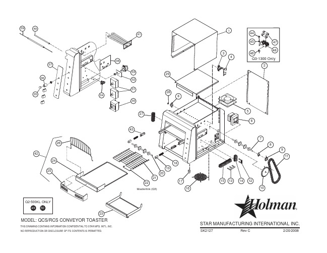
QCS-2-600H, QCS-2-800, RCS-2-600 Conveyor Toasters
Key Part
Number Number
Number Per Unit
Description
1 2 5 6
7 8 9 10 11 12 13 14 15 16 17 18 19 20 21
23 24 25 26 28 29
30 31 32 33 34 35 36
37
38
39
HEATER TUBE, QUARTS 220V (15.84 Ω, 720W) (UNIT = 13.9A)
HEATER TUBE, QUARTS 240V (19.2 Ω, 707W) (UNIT = 11.78 A)
ELEMENT, METAL
RCS
ELEMENT, SERPENTINE
RCS
HEATER TUBE, QUARTS 220V (11.2 Ω, 450W, 6.18A) (UNIT = 13.2 A)
HEATER TUBE, QUARTS 240V (12.6 Ω, 480W, 5.99A) (UNIT = 12.2 A)
HEATER TUBE, QUARTS 208V (15.5 Ω, 703W) (UNIT = 13.52 A)
BUSHING, FRONT
SHAFT, IDLER
BELT, CONVEYOR (10” X 35 - 1/2”)
【XXXX项目】二次开发设计说明书

文档编号:XXXX二次开发设计说明书XXXXXX有限公司目录1.引言 (3)1.1.编写目的 (3)1.2.项目背景 (3)1.3.参考资料 (3)2.二次开发结构 (3)2.1.软件结构 (3)2.2.条件与限制 (4)2.3.二次开发设计框架 (4)3.二次开发内容 (4)3.1.内容1(如:窗体定制—- ITEM属性表单的定制) (4)3.2.内容2 (5)3.3.内容n (5)4.接口设计 (5)4.1内部接口 (5)4.2外部接口 (6)5.数据结构设计 (6)5.1.库结构 (6)5.2.表结构 (6)6.出错处理设计 (6)6.1.出错信息 (6)6.2.补救措施 (6)6.3.系统维护设计 (6)7.其他 (6)1.引言1.1. 编写目的本文档主要针对系统的二次开发部分。
对在《实施总体设计方案》中描述的需要二次开发的内容,详细进行描述。
为编程人员、测试人员、实施人员和维护人员之间提供共同的参考依据,对XX软件功能及集成模块的实现作详细描述。
本说明书面向对象为编程人员、测试人员、实施人员和维护人员。
1.2. 项目背景本项目软件开发平台:本项目软件二次开发实施单位:1.3. 定义PLM (product life cycle management):产品生命周期管理PDM (product data management):产品数据管理BOM (bill of material):材料明细表CAPP(Computer Adied Process Planning):计算机辅助工艺设计PSE (product structure editor):产品结构编辑器ItemRevision:版本零部件……1.4. 参考资料《XXXX项目需求规格说明书》《XXXX项目总体设计方案》……2.二次开发结构2.1. 软件结构例如:TCEng软件的层次构成–Portal Java clients. 客户端–TCEng server 服务器端–Oracle 后台数据库–TCEngFS 文档服务器TCEng 存储数据的方式:结构化数据——存储于Oracle数据库中文件——存储于卷Volume中2.2. 条件与限制2.3. 二次开发设计框架客户程序类的层次如图所示:图:3.二次开发内容对于需要开发的内容有两类:一类是需要重新进行开发的内容,这相当于重新开发某一模块的功能。
RESECS Ⅱ高密度电法仪操作软件使用手册

-----------------------------------------------------------------------------------------------------Tools 工具 | Decoder test | Convert binary 编码器检测 二进制转换
北京欧华联科技有限责任公司
马晓雄
18791986217
RESECS 野外操作软件 使用手册
1
北京欧华联科技有限责任公司
马晓雄
010-82920623;18791986217
目录
1 1.1 1.2 1.2.1 1.2.2 1.2.3 1.2.4 1.2.5 1.2.6 1.2.7 1.2.8 1.2.9 1.3 1.3.1 1.3.2 1.3.3 1.3.4 1.3.5 1.4 1.4.1 1.4.2 1.4.3 1.4.4 1.4.5 1.5 1.5.1 1.5.2 1.5.3 1.5.4 1.5.5 1.5.6 1.5.7 1.5.8 1.5.9 1.5.10 1.5.11 软件描述 Program startup 启动程序 File 文件 Open project 打开任务 Open MCF file 打开 MCF 文件 Close project 关闭任务 Save project 保存任务 Save project as 保存任务为 Write config files 写程序参数的设置文件 Select default config files 选择缺省设置文件 Export data 输出数据 Exit RESECS 退出 RESECS Basic edit 基础编辑 General information 综合信息 Available electrode strings 实用的电极串 Field geometry 工区的几何参数 Select electrode configurations / project creation 选择电极装置/创建任务 External electrode selection 外围电极设置 Work edit 工作编辑 Activate electrode strings / set positions 激活电极串/设置位置 Recording channel / gain 纪录通道/增益 Injection timing 供电时间 Injection voltage 供电电压 Valid data range 有效数据范围 Options 选项 Data display, measurement and export 数据的显示、测量和输出 ASCII export ASCII码输出 Binary trace export 二进制码输出 Measure options 测量选项 Memory 存储 Backup 备份 Monitoring 监控 Plot size 绘图尺寸 Data display color 文本显示颜色 Color range 颜色范围 Screen saver 屏幕保护 4 6 6 6 7 8 9 9 9 10 10 11 12 12 12 13 14 19 19 20 20 21 24 26 27 27 29 30 31 32 33 33 36 36 37 39
V2程序中文教程(doc32)word资料42页
V2001中文教程前言本文描述了LAVENIR V2001 程序和其接口的特点和运行;对每幅屏幕显示、每一栏目及功能进行了详细的解释,对从键盘输入的命令及有关资料也进行了详细的描述。
目录1、程序概况(Program Overview)2、装入(Loading V2001)3、主菜单(Main Menu)4、图象屏幕(Graphics Screen)5、选择项菜单(Options Menu)6、D码编辑菜单(Dcode Mapping Menu)7、钻孔刀具码编辑菜单(Tools Mapping Menu)8、D码计数菜单(Counts of Dcode Menu)9、钻孔刀具码计数菜单(Tool counts Menu)10、走线/焊盘编辑菜单(Trace/pad editing Menu)11、特殊模块菜单(Special modules Menu)12、配置菜单(Configuration Menu)13、目录菜单(Directory Menu)14、层控制菜单(Layers Menu)15、环境菜单(Environment files Menu)16、报告文件(Report file)17、在线帮助(On line help)一、程序概要V2001程序能读和显示Gerber数据和提供观察、编辑、存数据、存参数和或得报告的软件工具,同时还具备在线帮助的功能。
观察和编辑绘图数据:元件的形状和尺寸的资料是安放在D码绘图菜单中,走线和焊盘以其真实的宽度和样子显示在图象屏幕上,同时可显示多到99层,对图象具有放大的功能,以便对数据进行仔细的核对,在屏幕上的可编网点会有助于定位、对准和编辑操作。
利用一组综合的编辑工具,可对各个走线和焊盘、在一个层上或多个层上的一组元件和整个层进行挑选和更改。
可按任意的尺寸和角度写上文字。
生产前的工作:V2001的特殊模块提供了生产前准备工作的功能。
铜面积计算模块:本模块可计算GERBER文件的印板的铜面积。
Google reCAPTCHA V2 用户指南说明书

Main Features:
- Forms. Allows applying Google reCAPTCHA V2 to 5 forms: Registration Form, Login Form, Forgot Password Form, Account Edit Form, Contact Us Form.
Type in Site and Security fields keys from the Google
reCAPTCHA configuration
-6-
Choose size of the widget: normal or compact
-7-
Select forms to display widget on
In order to add the Google reCAPTCHA V2 on a custom form follow next steps: 1. Add your custom form to the ‘Display on Forms’ list in configuration of the module to configure display. 2. Add the reCAPTCHA widget to form layout to display and validate the reCAPTCHA on front-end. 3. Create own observer to validate the reCAPTCHA on back-end.
xtait
INTRODUБайду номын сангаасTION
The extension lets protect web stores from bots and fraud attacks on 5 forms: Registration, Login, Forgot Password, Account Edit, Contact Us Forms.
V2视频会议系统使用手册

V2视频会议系统使用手册北京威速科技有限公司2013年3月目录1 设备连接示意图 (3)2 登陆方式 (5)3 会议界面及操作方法 (7)3.1 麦克风、摄像头等基本设置 (7)3.2 申请发言 (9)3.3 查看视频 (9)3.4 更换桌面布局 (10)3.5 文字交流区 (10)3.6 申请控制权 (10)3.7 数据协作 (11)3.8 主席权限(需要使用主席密码,即会议中主持人) (11)1设备连接示意图把电脑开机后,将USB摄像头的USB线接到电脑上,麦克风接电脑音频输入,电视机接电脑的音频输出(或接音箱)2登陆方式1、打开IE浏览器或360浏览器,进行基本设置IE---工具---Internet选项---安全选则:自定义级别。
在弹出的“安全设置”内有关Activex控件的项,改为:启用或者提示。
应用确定以后刷新浏览器会提示安装智能升级控件,点击安装,安装结束以后进行以下步骤,有的电脑业会不进行任何提示。
直接安装客户端即可。
也可通过右上角软件下载进行下载v2客户端2、打开IE(浏览器),在地址栏里输入IP地址http://XX:18181(内网地址),http://XX:18181 (外网地址),有内网条件的使用内网地址。
系统界面会显示多个会议室,直接单击会议室名称,输入昵称如南京、北京,输入会议密码:普通用户666666(以实际通知为准),点击进入会议。
如会议要求使用注册用户登录,则需要使用管理员分配的账号登录管理系统,然后进入需要参加的会议:3会议界面及操作方法3.1麦克风、摄像头等基本设置登陆会议以后可设置自己的麦克风和摄像头等设备:左上角普通-设置-音频、视频,选择自己使用的麦克风、摄像头设备。
3.2申请发言进入会议界面,系统默认无法发言。
发言需点击“页面左下角”第一个“申请发言”按钮申请发音,此时左边的用户列表用户名后面会出现喇叭标记。
3.3查看视频直接点击参会用户列表里面的用户名字即可查看相应的视频。
RE-2用户指南说明书

Op e r a ting In s trucTa b le of Con t entsQuick Set-Up (1)Sys t em De s crip t ion (1)De t ailed Com p o n ents De s crip t ion (2)Re c eiver Setup and Operation (2)Re c eiver Push-But t on Ref e r e nce Sheet (3)Handheld Trans m it t er (4)Body pack Trans m it t er (6)Ap p roval In f or m a t ion (6)Dis p lay Screens and Func t ions (7)Re c eiver Main Op e r a t i ng Screen (7)Re c eiver Con t rols and Func t ions (7)Trans m it t er Dis p lay s and Con t rols (7)Trans m it t er On/Off Lock-out (8)Guide l ines and R ec o m m en d a t ions for Best Per f or m ance (8)Trou b le Shoot i ng Guide (9)Tech n i c al Spec i f i c a t ions (11)Ac c es s o r ies and Parts (14)Fac t ory Ser v ice/War r anty (Lim i ted) (15)Sec t ion 1 - Quick Set-UpQuick Set-up: Re c eiver1.Do not con n ect the re c eiver to any other equip m ent yet!2.Con n ect the two an t en n as to the re c eiver.3.Plug the power sup p ly into the back of the re c eiver andinto an out l et4.Press the POWER switch. Dis p lay will light up.5.Press and hold the SET but t on un t il ClearScan TM showsand starts flash i ng on the right side of the screen.6.When ClearScan TM stops flash i ng, the re c eiver will au t o m at -i c ally set it s elf and dis p lay the clear e st group and chan n el.7.If y ou are us i ng a gui t ar, turn off the re c eiver. Press andhold SET while you turn the receiver on. A gui t ar sym b ol will ap p ear in the dis p lay to in d i c ate in s tru m ent mode.8.Turn the re c eiver off and con n ect the mixer or other au d iosys t em to the re c eiver XLR Con n ec t or or the ¼ inch Line Level Jack.9.Set the au d io mixer or other sy s t em in p ut level to min i-mum.10.Press the Power switch but t on in again.Re c eiver “Quick Set-up” is com p lete.Quick set-up: Trans m it t er1.With the Power Switch on the trans m it t er OFF, in s tall afresh al k a l ine bat t ery into the trans m it t er.2.Place the trans m it t er Power Switch to the ON po s i t ion.3.The Red Bat t ery Low Light near the dis p lay will flash onand then off. The dis p lay will also come on and dis p lay a group and chan n el.4.Press the SET but t on once and the Group num b er wille the up and down ar r ows to change the Group num b erto match the Group num b er dis p lay ed on the re c eiver.Press SET and the Chan n el Num b er will flash.e the up and down ar r ow but t ons to change the Chan n elto match the re c eiver. Press Set and noth i ng will be flash -ing. The chan n el is now set.7.If y ou are us i ng a body pack trans m it t er, plug the mi c ro -phone into the trans m it t er con n ec t or. If us i ng a gui t ar, turn the trans m it t er off and wait un t il dis p lay is blank. Hold SET down and turn the trans m it t er on. A gui t ar sy m b ol should ap p ear on the dis p lay. Plug the cord into the trans -mit t er and gui t ar.Trans m it t er “Quick Set-up” is com p lete.Quick set-up:Sys t em Op e r a t ion1.With the trans m it t er and re c eiver on, mon i t or the dis p layscreen. Note that the RF (1-100) Bar graph should in d i c ate near the 100 mark. The AF Bar should show very lit t le, if any, in d i c a t ion un t il you talk or sing into the mi c ro p hone.Ad j ust the trans m it t er gain con t rol if nec e s s ary to cause the AF Bar Graph to peak near -6 to -3 but not over +3 for best per f or m ance.2.Set the mixer/amp gain.3.Talk or sing into the mi c ro p hone or play the gui t ar at anor m al vol u me. You should hear au d io com i ng out of the sy s t em.4.If us i ng the un b al a nced 1/4" out p ut, you may have to ad -just the gain (via the con t rol next to the con n ec t or on the back panel) to match the level found when sing i ng or play -ing with a wired con n ec t ion."Quick Set-up" is now com p lete.Please en j oy your RE-2 sys t em.Sec t ion 2 - Sys t em De s crip t ionThe RE-2 Wire l ess Mi c ro p hone sy s t em com b ines fre q uency agil i ty and ease of use like no other. The RE-2 trans m it t ers and re c eiv e rs op e r a te over a 24 MHz band w idth in the UHF por t ion of the Ra d io Fre q uency spec t rum.Sys t em Fea t ures In c lude:The high qual i ty au d io cir c uitry and ad v anced Ra d io Fre -quency (RF) sig n al pro c ess i ng of f er broad c ast qual i ty sig -nal-to-noise and au d io clar i ty.•Ad v anced ClearScan TM tech n ol o gy for se l ect i ng the clear e st avail a ble chan n els in intermodulation free groups.•Com p letely pro g ram m a b le in25kHz steps for over 950 pos s i b le fre q uen c ies.•LCD Dis p lay s for ease of view i ng-Group, Chan n el, Fre -quency, Bat t ery Sta t us, Di v er s ity Ac t iv i ty, Au d io Me t er and RF Me t er.•Pat e nted Phase Di v er s ity Sy s t em•Ad j ust a ble Un b al a nced Line Level 1/4 inch out p ut jack •Bal a nced XLR out p ut jack for fixed Mi c ro p hone Level or ad j ust a ble Line Level •Front Panel Power ON/OFF Switch•Front Panel Soft w are Con t rol of Squelch set t ings •Dou b le Squelch (Am p li t ude and Tone) sy s t em pre v ents false squelch•Lock o ut fea t ure to pre v ent ac c i d en t al chan n el changes •"Smart" bat t ery fea t ure in the trans m it t er means there is no wrong ori e n t a t ion•Power Lock On fea t ure pre v ents ac c i d en t al turn off •Bat t ery level dis p layed at the re c eiverSec t ion 3 - De t ailed Com p o n ents De s crip t ionR e c eiver Setup and Op e r a t ion1.Place the re c eiver and an t en n as where there is a clear lineof sight to the area where the trans m it t er will be used. Ro -tate the an t en n as to sep a r ate them by 90 de g rees.2.Con n ect the power sup p ly cord to the re c eiver. Plug thepower sup p ly into an AC out l et. Turn the re c eiver on and con f irm that it is ON by check i ng the main dis p lay screen. Cau t ion: Please make sure the AC power sup p ly is the cor -rect volt a ge for your lo c al re q uire m ents be f ore it is plugged into the wall.3.Man u al Chan n el Change.Press the SET but t on and theGroup num b er will start to flash. The Up and DOWN but -tons al l ow y ou to scroll through the fac t ory set group.When the group you de s ire is dis p layed, press SET to se -lect that group and the Chan n el Num b er will start flash i ng.Scroll to the de s ired chan n el and press SET to se l ect. The num b ers will stop flash i ng and the new group and chan n el are in s talled.4.Fre q uency As s ign m ent (Out s ide of pre s et Groups andChan n els), press SET and UP at the same time and the group and chan n el will go blank and the Fre q uency will start flash i ng. Use UP/DOWN to scroll in 25 KHz steps to the de s ired fre q uency. Press SET and the fre q uency will be se l ected and stop flash i ng. Press Set and UP at the same time to re t urn to group and chan n el op e r a t ion. Hint: hold -ing in the Up or Down key will in c rease the speed of the scroll. Just re l ease and press again for fine con t rol 5.Ad v anced ClearScan:TM This fea t ure au t o m ates the pro -cess of find i ng a clear group of inter-mod u l a t ion free chan n els and the clear e st chan n els within those groups.a.ClearScan TM, for Groups: From the main dis p layscreen, push SET once and the Group Num b er willflash. While Group is flash i ng, press and hold SET un -til ClearScan TM ap p ears, re l ease the set key. When thescan is com p leted, the dis p lay will show the groupwith the most clear chan n els and the Chan n el num b erwill in d i c ate how many clear chan n els are in thatgroup. Use the UP/DOWN key s and to view othergroups and press SET to se l ect a group. The Groupwill be set and the Chan n el will start to flash. Se l ect achan n el man u a lly or use ClearScan TM for Chan n els.ClearScan TM for Chan n els: To scan for the clear e stchan n el in a group, press and hold set while the Chan -nel is flash i ng un t il ClearScan TM ap p ears, re l ease theSET but t on. When the scan is com p lete, the dis p laywill show the clear e st avail a ble chan n el. UseUP/DOWN to scroll through the other avail a ble chan -nels rank from clear e st to least clear (but still avail a blefor use, ClearScan TM will not dis p lay any chan n el thatcan't be used). Press SET to se l ect the chan n el.b.c.Auto ClearScan:TM This func t ion will find the clear -est group and chan n el with the press of just one but t on.With noth i ng flash i ng, press and hold the SET but t onun t il ClearScan ap p ears on the right side of the screen.When the scan is com p lete, the re c eiver will be set tothe clear e st chan n el in the clear e st group.1.Power ON/OFF2.Graph i c al Dis p laya.Chan n el Dis p layb.Fre q uencyc.Bat t ery Strength In d i c a t ord.Di v er s ity In d i c a t ore.RF Strength ofSig n al In d i c a t orf.Au d io Level In d i c a t or3.Dis p lay Con t rol But t ons(Set/Up/Down)4.Power Con n ec t or5.XLR Bal a nced Mic/Line Level Au d io Out p utLine Level Ad j ust a ble6.Un b al a nced Line Level Au d io Out p utCon n ec t or with Level Ad j ust m ent7.TNC An t enna In p ut Con n ec t ors8.Power Cord Re t ainerRE-2Fig u re 2 - RE-2 Back Panel2Fig u re 1 - RE-2Front PanelProper An t enna OrientationR E-2R e c eiver Con t rols,Con n ec t ors,and In d i c a t orsNOTE: Groups x,x,x, and x are set up to work with the other US fre q uency band (A and B). These groups are listed last no mat t er how many open chan n els are avail -able. If you are us i ng a mix of Band A and Band B, scroll down to these groups and use the clear e st group.6.Change Lock-Out: By press i ng and hold i ng the UP andDOWN ar r ow keys to g ether for 3 sec o nds, the SET key is dis a bled.To re a c t i v ate the SET key, sim p ly press and hold the UP and DOWN keys again for 3 sec o nds. This fea t ure can be use f ul when the re c eiver is in a lo c a t ion where un -au t ho r ized per s on n el have ac c ess to the re c eiver.7.For set up, make sure the mixer or amplifier in p ut used forthe RE-2 is muted or turned down to a min i m um level.8.Plug an au d io ca b le (not sup p lied) into the 3 pin XLR or1/4 inch out p ut of the RE-2.a.NOTE: The XLR con n ec t or is the pre f erred con n ec -tion since the out p ut is bal a nced and will be more im -mune to noise for lon g er runs of ca b le al t hough ei t hercan be used with good re s ults. If the 1/4 inch con n ec t oris used, ad j ust the out p ut level on the back panel to 12o'clock (mid w ay in the range) to start and ad j ust later ifnec e s s ary.Now re f er ahead to trans m it t er setup and re t urn to step 9 when that is com p leted.9.With the trans m it t er on, speak into the mi c ro p hone or playthe guitar. Turn up the level on the mixer or am p li f ier un t il you are able to hear the de s ired sig n al. If no au d io is pres -ent, re p eat setup and re f er to the trou b le s hoot i ng sec t ion.NOTE: If the 1/4 inch out p ut is used, it may be nec e s s ary to ad j ust the re c eiver out p ut un t il the vol u me level from the wire l ess sy s t em ap p rox i m ates the level of an equiv a-lent wired mi c ro p hone/in s tru m ent.10.Squelch Ad j ust m ent - The squelch set t ing can be used tomax i m ize range or im m u n ity to noise. Press and hold Up for 3 sec o nds. The cur r ent squelch set t ing will be dis -play ed.Ad j ust the squelch us i ng the UP/DOWN key s.Max i m um squelch(9)max i m izes noise im m u n ity but lim -its the range. Min i m um squelch (1) will max i m ize the range but al l ow more noise to break through the squelch. Press SET to save the new squelch set t ing.R e c eiver Push-But t on R ef e r e nce SheetDis p lay Sta t us But t on Press Func t ion Ac t i v ated Edit Ac c ept Noth i ng Flash i ng Press and hold SET Auto ClearScanän/a n/a Noth i ng Flash i ng SET Edit Group -Group will flash??SETGroup Flash i ng Press and hold SET ClearScanä Group - list clear groups in or d er??SET Group Flash i ng SET Edit Chan n el - Chan n el will flash??SET Chan n el Flash i ng Press and hold SET ClearScanä Chan n el - list clear chan n els in or d er??SET Noth i ng Flash i ng Press and hold Up Edit Squelch Set t ing??SET Noth i ng Flash i ng Press and hold Up & Down Edit Lock - Se c ure will ap p ear n/a n/a Edit Lock On Press and hold Up & Down Re t urn to Ac c ess Mode n/a n/a Power Off Press and hold SET Tog g le be t ween Gui t ar and V oice mode n/a n/a Noth i ng Flash i ng Press SET and Up Tog g le to Fre q uency Mode - Freq will flash??SET Fre q uency Flash i ng Press and hold SET ClearScanä Band - Clear Scan will flash n/a SET ClearScanä Band Run n ing Press SET End ClearScanä Band af t er next full scan n/a n/a ClearScanä Band Re s ults n/a8Clear e st fre q uen c ies listed??SET Fre q uency Mode Press SET and Up Re t urn to Group and Chan n el Mode n/a n/a Noth i ng Flash i ng Press and hold Down Dis p lay Soft w are Re v i s ion n/a n/aHandheld Trans m it t er HTU-2Fig u re 3Handheld Trans m it t erHTU-2 Con t rols, Con n ec t ors, and In d i c a t orsHandheld Trans m it t er Setup and Op e r a t ion1.In s ert Bat t ery. Re m ove the bat t ery com p art m ent cover byun s crew i ng it com p letely. In s ert a 9V bat t ery, ter m i n al end first into the bat t ery com p art m ent.NOTE: The HTU-2 unique de s ign al l ows the bat t ery to be in s erted and used re g ard l ess of the pos i t ive and neg a t ive ter m i n al po s i t ion.2.With bat t ery com p art m ent still open, turn the unit soyou can see the dis p lay and the con t rol panel. Turn the unit on by slid i ng the power switch for w ard to the on po s i t ion.The bat t ery low LED will light for a sec o nd and the dis -play will show the Group and Chan n el num b ers.3.Change the group and chan n el num b ers to match those dis p lay ed on the re c eiver by press i ng SET. The Group num b er will flash and can be changed with the UP/DOWN key s. Once the de s ired group num b er is show i ng, press SET to se l ect and the Chan n el num b er will flash. Se l ect the Chan n el and press SET again. The flash i ng will stop and the chan n el is now set.4.Other Screens: Press SET and DOWN at the same time to dis p lay the bat t ery level. Press SET and DOWN again to dis p lay fre q uency. Press them one more time to re t urn to Group and Chan n el .Fig u re 4Trans m it e r5.Fre q uency Edit Mode - Press SET from the fre q uencydis p lay screen to en t er fre q uency edit mode. Press the Up and Down to ad j ust fre q uency in 25 kHz in c re m ents. Hold -ing the Up or Down but t ons down will auto step the fre -quency ; slowly at first, then quickly. You can also en t er fre q uency edit mode by press i ng SET and UP at the same time from ei t her the Group and Chan n el or Bat t ery sta t us dis p lay screens. Press i ng SET and UP at the same time form the Fre q uency dis p lay screen will en t er Group and Chan n el edit mode.6.Power Lock Out - Press SET, UP, and DOWN at the same time and hold 3 sec o nds to lock the power switch on. To turn the unit off, place the power switch in the OFF po s i -tion and push SET, UP, or DOWN. To re m ove the lock,press SET, UP, and DOWN again at the same time and hold 3 sec o nds . A one-time only ON-LOCK mode can also be en t ered by quickly cy c ling the power switch three times.7.Set Key Lock-Out , by press i ng and hold i ng the UP andDOWN ar r ow keys to g ether for 3 sec o nds, the SET key is dis a bled. To re a c t i v ate the SET key sim p ly press and hold the UP and DOWN keys again for 3 sec o nds.SET45683121. Main Dis p lay - LCD (Chan n el, Fre q uency or Bat t ery Level In d i c a t ion)2. Bat t ery Low LED - Lights when bat t ery is low 3. Power On/Off Switch 4. Set Switch5. Chan n el/Fre q uency Up Switch6. Chan n el/Fre q uency Down Switch7. Mi c ro p hone Gain8. 9V Bat t ery Holder9. Bat t ery Cover - Screw type.8.Ver i fy re c ep t ion. With the trans m it t er and re c eiver on andmatch i ng Group and Chan n el, the main re c eiver dis p lay should be in d i c at i ng a RF sig n al on the bar graph. Speak into the mi c ro p hone and the Au d io Me t er bar graph should in d i c ate au d io sig n al pres e nce. If the level me t ers do not show re c ep t ion, make sure the chan n els are match i ng and re f er to the trou b le shoot i ng sec t ion.9.Ad j ust m ent of the trans m it t er au d io gain - If nec e s s aryThe trans m it t er au d io gain is fac t ory set at the mid d le of the range, which should be suit a ble for most ap p li c a t ions.For loud or soft speak e rs/sing e rs, a gain ad j ust m ent may be nec e s s ary. Have the speaker or singer use the mi c ro -phone in a nor m al per f or m ance level voice. The Au d io Me t er in the main re c eiver dis p lay screen should show peaks around the -3dB level. If the me t er peaks all the way to the right or well be l ow the -3dB level, ad j ust the trans -mit t er au d io gain.Bodypack Trans m it t er-BPU-2Fig u re 5Bodypack Trans m it t erBPU-2Con t rols, Con n ec t ors, and In d i c a t orsTo ad j ust the trans m it t er gain, gently in s ert the pro v ided screw d river (or other 3/32 - 2.5 mm screw d river) into the ad j ust m ent hole op p o s ite the dis p lay screen. Turn lightly un t il the screw d river tip goes into the ad j ust m ent level con t rol. Gently turn coun t er c lock w ise un t il the con t rol stops (the mi c ro p hone out p ut is at min i m um but not off).Slowly turn the gain con t rol up (clock w ise) while speak -ing/sing i ng into the mi c ro p hone and the au d io me t er shows peaks around -3 dB.NOTE: Op e r a t i ng with the trans m it t er au d io gain set as high as pos s i b le (with o ut dis t or t ion or peaks all the way to the right end of the me t er) will re s ult in the best per f or -mance and high e st sig n al to noise ra t io.10.Test Per f or m ance. Go back to Sec t ion 3. Re c eiver Setupand Op e r a t ion - Step 9 to com p lete sys t em set up and test.Fig u re 6Con t rol ViewFig u re 7Top ViewOFF4231.An t enna - flex i b le 1/4 wave an t enna2.Power On/Off Switch3.Bat t ery Low LED In d i c a t or4.TA4Au d io Con n ec t or5.LCD Dis p lay (Chan n el, Fre q uency orBat t ery Level Indication)6. Dis p lay Con t rol But t ons (Set/Up/Down)7.Belt Clip (Re m ov a ble,not shown)8.9V Bat t ery Compartment9.Au d io Gain AdjustmentBodypack Trans m it t er Setupand Op e r a t ion1.In s ert Bat t ery. Pinch the bat t ery door tabs in w ard andpull the door open. In s ert a 9V bat t ery as in d i c ated by the +/- in the holder.2.With bat t ery com p art m ent still open, turn the unit on withPower switch on the top panel. The bat t ery low LED will light for a sec o nd and the dis p lay will show the Group and Chan n el num b ers.3.Change the group and chan n el num b ers to match thosedis p lay ed on the re c eiver by press i ng SET. The Group num b er will flash and can be changed with the UP/DOWN key s. Once the de s ired Group num b er is show i ng, press SET to se l ect and the Chan n el num b er will flash. Se l ect the Chan n el and press SET again, the flash i ng will stop and the chan n el is now set.4.Set Key Lock-Out. By press i ng and hold i ng the UP andDOWN ar r ow keys to g ether for 3 sec o nds, the SET key is dis a bled. To re a c t i v ate the SET key, sim p ly press and hold the UP and DOWN keys again for 3 sec o nds.5.Ver i fy re c ep t ion. With the trans m it t er and re c eiver on andmatch i ng Group and Chan n el, the main re c eiver dis p lay should be in d i c at i ng a RF sig n al on the bar graph. If the level me t er does not show re c ep t ion, make sure the chan -nels are match i ng and re f er to the trou b le shoot i ng sec t ion.6.At t ach the Mi c ro p hone or Guitar.Mi c ro p hone:Plug the mi c ro p hone ca b le into the top panel of the BPU-2. Speak into the mi c ro p hone and the Au d io Me t er bar graph should in d i c ate au d io sig n al pres e nce.Gui t ar: Turn off the bodypack, press and hold SET while you turn the bodypack on. A gui t ar sym b ol will ap p ear in the dis p lay to in d i c ate in s tru m ent mode. Re p eat the pro -cess hold i ng SET on the re c eiver as it is pow e red up to re -turn to voice mode. Plug in the MAC-G3 gui t ar ca b le.Strum the gui t ar and the Au d io Me t er bar graph on the re -ceiver should in d i c ate au d io sig n al pres e nce.7.Ad j ust m ent of the Trans m it t er Au d io Gain-(if nec e s -sary). The trans m it t er au d io gain is fac t ory set at the mid -dle of the range, which should be suit a ble for most ap p li c a t ions. For loud or soft speak e rs/sing e rs, a gain ad -just m ent may be nec e s s ary.Have the speaker or singer use the mi c ro p hone in a nor m al per f or m ance level voice. The Au d io Me t er in the main re -ceiver dis p lay screen should show peaks around the -3 dB level. If the me t er peaks all the way to the right or well be -low the -3 dB level, ad j ust the trans m it t er au d io gain.To ad j ust the trans m it t er gain, gently in s ert the pro v ided screw d river (or other screw d river) into the ad j ust m ent po -ten t i o m e t er.Gently turn coun t erclock w ise un t il the con t rol stops (the mi c ro p hone out p ut is at min i m um but not off).Slowly turn the gain con t rol up (clock w ise) while speak -ing/sing i ng into the mi c ro p hone or strum m ing the guitar and the au d iome t er shows peaks around -3 dB.NOTE: Op e r a ting with the trans m it t er au d io gain set as high as pos s i b le (with o ut dis t or t ion or peaks all the way to the right end of the me t er) will re s ult in the best per f or -mance and high e st sig n al to noise ra t io.Other Screens: Press SET and DOWN at the same time to dis p lay the bat t ery level. Press SET and DOWN again to dis p lay fre q uency. Press them one more time to re t urn to Group and Chan n el.8.Fre q uency Edit Mode - Press SET from the fre q uencydis p lay screen to en t er fre q uency edit mode. Press the Up and Down to ad j ust fre q uency in 25 kHz in c re m ents. Hold -ing the Up or Down but t ons down will auto step the fre -quency; slowly at first, then quickly. You can also en t er fre q uency edit mode by press i ng SET and UP at the same time from ei t her the Group and Chan n el or Bat t ery sta t us dis p lay screens. Press i ng SET and UP at the same time form the Fre q uency dis p lay screen will en t er Group and Chan n el edit mode.9.Power Lock Out - Press and hold SET, UP, and DOWN atthe same time and hold for 3 sec o nds to lock the power switch on. To turn the unit off, place the power switch in the OFF po s i t ion and push SET, UP, or DOWN. To re -move the lock, press SET, UP, and DOWN again at the same time and hold for 3 sec o nds. A one-time only ON-Lock mode can also be en t ered by quickly cy c ling the power switch three times.10.Test Per f or m ance - Go back to Sec t ion 3 - Re c eiver Setup& Op e r a t ion, Step 9 to com p lete sys t em set up and test.AP P R OV AL IN F OR M A T IONThe Elec t ro-V oice/Telex Trans m it t ers are Ty pe Ac c epted un d er United States Fed e ral Com m u n i c a t ions Com m is s ion CFR 47, Part 74 and In d us t ry Can a da RSS123.The Elec t ro-V oice/Telex Re c eiver is ap p roved un d er United States Fed e ral Com m u n i c a t ions Com m is s ion CFR 47, Part 15 and In d us t ry Can a da RSS210.Li c ens i ng of Elec t ro-Voice/Telex equip m ent is the us e rs re s pon s i b il i ty and Licensability de p ends upon the us e rs clas s i f i -ca t ion, us e rs ap p li c a t ion and fre q uency se l ected. Elec t ro-Voice/Telex strongly urges the user to con t act the ap p ro p ri a te tele c om m u n i c a t ions au t hor i ty for any de s ired clar i f i c a t ion.CAU T ION: Any changes or mod i f i c a t ions made to the above equip m ent could void the us e rs au t hor i ty to op e r a te the equip m ent.Sec t ion 4 - Re c eiverFig u re 8Main Op e r a t i ng ScreenSquelch Ad j ust m ent ScreenFig u re 9Squelch Adjustment ScreenTrans m it t er Dis p lay and Con t rolsFig u re 10Trans m it t er Dis p lay and Con t rols1. Squelch Level ·············1-10 1.[UP] + [DOWN] ad j ust the squelch level2. SET saves the squelch level shown and re t urns youto the main screenDis p lay:Con t rols:1.Press and hold SET for 3 sec o nds starts Auto ClearScan ™2.Press SET once, Group starts flash i ng, ad j ust with UP andDOWN 2.a With Group flash i ng, press and hold SET for 3sec onds to start Group Scan .3.Press SET twice, Chan n el starts flash i ng, ad j ust with UP andDOWN 3.a With Chan n el flash i ng, press and hold SET for 3sec o nds to start Chan n el Scan 4.Press SET and UP at the same time to en t er Fre q uency Mode 5.Press and hold UP for 3 sec o nds to ad j ust Squelch6.Press and hold SET dur i ng power up to en t er In s tru m ent Mode7.[UP] + [DOWN] for 3 sec o nds Sets/Re s ets Edit Lock o ut1.Group Num b er ···········10 fac t ory set2.Chan n el Num b er··········01 to 103.Fre q uency ···············Dis p lay ed in Mega H ertz4.Bat t ery Sta t us············100 to 0 Pct in25 Pct steps/Flash if low5.Au d io VU Me t er ·········-30 VU to + 3 VU6.RF Sig n al Strength ········1µV to 100 µV7.An t enna Di v er s ity Stat us ···left or right an t enna 8. ClearScan ™·············In d i c ates Scan is in prog r ess 9.Gui t ar Sy m b ol ···········In d i c ates In s tru m ent ModeCon t rols:Dis p lay:1.Group and Chann el 2.Bat t ery Level in Per c ent a ge 3.Fre q uency1.Press SET once, GP will flash, use UP and DOWN to ad j ust2.Press SET again to ac c ept GP, CH will flash, ad j ust with UP/DOWN3.Press SET again to ac c ept CH and chan n el will be in s talled4.Press SET and DOWN at the same time to change dis p lay mode5.Press SET and UP to en t er Fre q uency Set Mode6.Press SET and DOWN to re t urn to the Group/Chan n el Mode7.Press and hold UP and DOWN for 3 sec o nds to lock out SET8.Press and hold UP and DOWN again to ac t i v ate SET9.Press and hold UP, DOWN, and SET to lock power (see Sec t ion 4)10.Press and hold UP, DOWN, and SET to un l ock powerDis p lay:Controls:Trans m it t er On/Off Lock-OutThere are two On/Off lock o ut modes avail a ble, One Time and Everytime.One Time: Cy c le the power switch 3 times in un d er 3 sec o nds and On-Loc will be dis p layed for a sec o nd and then re t urn to nor m al op e r a t ion. The power switch alone will no lon g er turn the unit off. To turn the unit off, put the power switch in the off po s i t ion (On-Loc will be dis p layed) open the bat t ery door and press [Set], [Up], or [Down] and the unit will power down. The next time the unit is pow e red on, the power switch will op e r a te nor m ally.Everytime Use: With the unit on and op e r a t i ng in the nor m al mode, press and hold [Set], [Up], and [Down] for 3 sec o nds. On-Loc will be dis p layed and the power switch alone will no lon g er turn the unit off. To turn the unit off, put the power switch in the off po s i t ion, (On-Loc will be dis p lay ed), open the bat t ery door and press [Set], [Up], or [Down] and the unit will power down. The next time the unit is pow e red on, the On-loc func t ion will still be on. To en a ble the power switch, press and hold [Set], [Up], and [Down] for 3 sec o nds (On-Off will be dis p layed).Guide l ines and R ec o m m en d a t ionsfor Best Per f or m anceCom p at i b il i tyThe trans m it t er and re c eiver must be of the same fre q uency band and set to the same group and chan n el in or d er to work to g ether. The RE-2 is avail a ble in two fre q uency bands, A and B. The band in f or m a t ion is avail a ble in the Group/Chan n el edit screen on the re c eiver, the bot t om la b el on the handheld trans m it t er, and on the back panel la b el on the bodypack.Us i ng Mul t i p le Wire l ess Sys t emsIf two or more RE-2 sys t ems and/or other UHF/VHF wire l ess sys t ems are be i ng used in the same lo c a t ion, proper fre q uency co o r d i n a t ion is nec e s s ary to avoid in t er f er e nce.All chan n els in the RE-2 fac t ory set groups are de s igned to work together, so if chan n els from just one group are used no fur t her coordination is re q uired. Con t act your dealer or Telex for as -sis t ance if you are plan n ing more sys t ems or us i ng the RE-2 with other wire l ess equip m ent.IM P OR T ANT NOTE: Al w ays use the small e st pre s et group that meets your needs. For in s tance, if you want to set up 6 units, use one of the groups of 8 fre q uen c ies. The smaller the pre s et group, the more com p at i b le the fre q uen c ies are.Mul t i p le Sys t emsand Ad v anced ClearScan TMBe c ause all of the chan n els in the fac t ory set groups are com -pat i b le,Ad v anced ClearScan TM can be used to set up mul t i p le sy s t ems quickly and with con f i d ence. When set t ing up more than one sys t em, set up the first sys t em us i ng the ClearScan TM All func t ion. Once the work i ng Group has been es t ab l ished, leave the first trans m it t er on, set the next re c eiver Group to the work i ng Group and run ClearScan TM Group. This will pro v ide the next clear e st chan n el in that group. Set the trans m it t er to match, leave it on and re p eat un t il all the sys t ems are set up. If you run out of clear chan n els in one group but need to set up more sys t ems, contact your dealer or Telex for as s is t ance in choos -ing ad d i t ional fre q uen c ies.Po t en t ial Sources of In t er f er e nceThere are many po t en t ial sources of in t er f er e nce for y our wire l ess sy s t em.Any elec t ronic prod u ct that con t ains dig i t al cir c uitry in c lud i ng dig i t al sig n al pro c es s ors (re v erb/multi-effects units), elec t ronic key b oards, dig i t al light i ng con t rol l ers, CD and DVD play e rs, and com p ut e rs, all emit RF en e rgy that can ad v ersely af f ect the per f or m ance of your wire l ess sys t em. It is al w ays best to place the re c eiver as far away as pos s i b le from these de v ices to min i m ize po t en t ial prob l ems.An a l og and Dig i t al Tele v i s ion stations can also in t er f ere with your wire l ess sys t em. The RE-2 is de s igned to op e r a te over 24 MHz of RF band w idth, which cov e rs four TV chan n els. The fac t ory pre s ets on the RE-2 are op t i m ized for conditions where one or pos s i b ly two of the four stations are cov e red in your area. If three of the four sta t ions are used in your area, it will se v erely limit the num b er of sys t ems that will op e r a te to -gether and you should be us i ng a dif f er e nt band.Bat t ery R ec o m m en d a t ionsFresh9-volt al k a l ine bat t er i es form a qual i ty man u f ac t urer will yield the best per f or m ance from your RE-2 trans m it t ers. Re c harge a ble 8.4-volt Ni-Cad bat t er i es can be used but will re s ult in much shorter op e r a t ion time.When the trans m it t ers are turned on, the red bat t ery LED will flash once if the bat t ery is good. If the light does not light or stays lit con t in u o usly, the bat t ery is weak or dead. If the light co m es on dur i ng use, the bat t ery is weak e n i ng and should be re p laced as soon as pos s i b le. If sound qual i ty de g rades during use, it may be the re s ult of a weak e n i ng bat t ery.Cau t ion: The bat t ery level in d i c a t ors, on the trans m it t ers and re c eiver dis p lays, are based on the use of al k a l ine bat -ter i es. Use of other bat t ery types will re s ult in false read -ings on these in d i c a t ors al t hough the bat t ery low LED on the trans m it t ers will op e r a te nor m ally.Re c eiver and An t enna Place m entDo not place the re c eiver near a large metal ob j ect or sur f ace. Lo c ate the re c eiver as close as pos s i b le to the area where the trans m it t er will be used. Ide a lly, po s i t ion the re c eiver/an t en n as within sight of the trans m it t er. When us i ng mul t i p le sys t ems, do not al l ow an t en n as to cross or touch each other. For best re -sults with mul t i p le re c eiv e rs, use an APD4 an t enna split t er. (See Sec t ion 7).。
REC-V2 技术文档说明书

技术支持:025-52831196
雍异官网: 雍异社区:
语音识别模块 REC-V2 ——用户手册
如果连接了功能扩展模块,下载接到排线的方法不变,在功能扩展口直接接 到扩展模块的下载端口即可
技术支持:025-52831196
Io-11/busy O
说明 电源正极,可接 5V TTL 串口的接收端 TTL 串口的发射端 电源负极 模块 IO1 模块 IO2 模块 IO3 模块 IO4 模块 IO5 模块 IO6 模块 IO7 模块 IO8 模块 IO9 模块 IO10 模块在没有接通电源前,模块下载状态设置管脚与 GND 连接,再给模块接 通电源,此时,模块即可进入下载状态。 模块忙信号输出脚,当该脚输出高电平时,无法进行语音识别。
技术支持:025-52831196
雍异官网: 雍异社区:
语音识别模块 REC-V2 ——用户手册
资源简介
识别词条:每个模态 50 个 可构建模态数:与存储量有关,至少 300 个识别模态 识别率:97% 30DB 噪声条件 最远识别距离:6 米 30DB 噪声条件 识别响应时间:小于 0.5 秒 图形化开发环境支持:NewWay Speech Recognition Winter 2013 IO 数量:10 个 IO IO 方向:输入/输出双向接口 串口数量:1 个串口 串口方向:输入/输出双向接口 串口波特率:可定制 板载 FLASH 容量:64M 是否支持 SD/TF 卡扩展:是 最大 TF 卡支持:2G MP3 解码能力:0~80Kbps
工作湿度
95%
10%
相对湿度,无冷凝
下载器的链接
下载器可以直接接到模块上面的 TTL 的串口,下载器本身是一个 TTL 的串 口,可以为模块供电,因此,绝对不能把下载器接反,接反会把模块烧毁,特别 需要注意。
V2监控录波功能调试说明
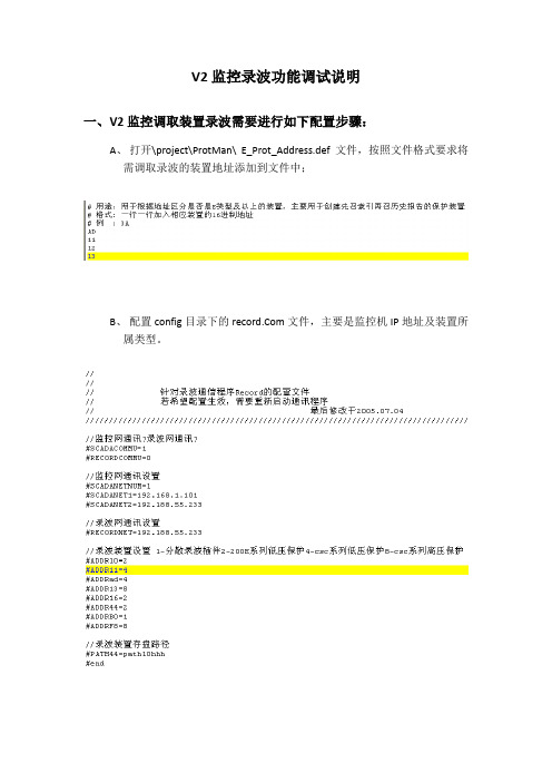
V2监控录波功能调试说明一、V2监控调取装置录波需要进行如下配置步骤:A、打开\project\ProtMan\E_Prot_Address.def文件,按照文件格式要求将需调取录波的装置地址添加到文件中;B、配置config目录下的文件,主要是监控机IP地址及装置所属类型。
C、配置config目录下的record.txt文件,按照文件中已有实例配置。
CSC系列保护装置上送的录波文件为comtrade格式的数据文件(dat)和数据配置文件(cfg)。
cfg文件中描述了装置上送的录波通道名称、类型、数量、单位、系数、偏移量、记录时间等信息,我们在进行录波分析时通过读取cfg文件将录波数据显示在分析画面内。
但是CSC系列的低压保护装置上送的cfg文件中对通道名称、类型、单位等没有详细定义(图1),我们需要在record.txt文件中对未定义内容进行定义(图2),这样在调取低压保护装置录波时程序会自动将record.txt文件中定义的描述添加到cfg文件,中生成带通道名称、类型、单位等描述的文件(图3)。
需要注意的是record.txt文件中最多可定义10路遥测值,如果定义大于10会影响cfg文件的生成。
图1:未定义record.txt时生成的cfg文件图2:在record.txt中进行配置定义图3:通过读取record.txt文件生成的cfg文件D、启动bin文件夹下的record进程,在“保护管理”界面下调取装置录播等历史记录。
二、cfg文件格式说明//站名,装置的特征,COMTRADE标准的修改年份,四方变,1997//通道的数量,遥测通道数量,遥信通道数量26,10A,16D//通道索引号,通道名称,相别,备用,单位,转换系,偏移量,通道时滞,CT,PT1,IA,A,0,A,0.000100,0.000000,0,0.000000,0.0000002,IB,B,0,A,0.000100,0.000000,0,0.000000,0.0000003,IC,C,0,A,0.000100,0.000000,0,0.000000,0.0000004,3I0,D,0,A,0.000100,0.000000,0,0.000000,0.0000005,UA,A,0,KV,0.000100,0.000000,0,0.000000,0.0000006,UB,B,0,KV,0.000100,0.000000,0,0.000000,0.0000007,UC,C,0,KV,0.000100,0.000000,0,0.000000,0.0000008,3U0,D,0,KV,0.000100,0.000000,0,0.000000,0.0000009,UX,A,0,KV,0.000100,0.000000,0,0.000000,0.00000010,UN,A,0,KV,0.000100,0.000000,0,0.000000,0.000000//通道索引号,,,是否取反11,开关,,,012,保护启动,,,013,保护动作,,,014,速断,,,015,过流1,,,016,过流2,,,017,过流3,,,018,DIG08,,,019,DIG09,,,020,DIG10,,,021,DIG11,,,022,DIG12,,,023,DIG13,,,024,DIG14,,,025,DIG15,,,026,DIG16,,,0//线路频率50//数据文件中采样率数字4//以赫兹(Hz)为单位的采样率,在该采样率下最后一次采样数1000,9911000,57561000,58251000,123//日期/时间标记03/10/2009,17:36:15.28503/10/2009,17:36:15.285ASCII技术支持:毕振军2009-3-23。
环境卫星2级产品简介与使用说明

HSI数据文件构成
与产 品名 称对 应
satRowBias scenePath sceneRow scenePathBias sceneRowBias sunElevation sunAzimuthElevation recStationId sceneDate sceneTime imagingStartTime imagingStopTime satOffNadir mirrorOffNadir
7、(4)2级数据产品使用简介-1
2级数据以压缩方式提供,解压后,所有文件在同一文件夹内 CCD、IRS图像文件为DN值产品,数据格式为GeoTiff,用ENVI、 ERDAS、ARCGIS等软件均可正常读取
CCD、IRS数据文件构成
7、(4)2级数据产品使用简介-2
HSI图像文件为为辐亮度产品,数据格式为HDF5,ENVI、ERDAS、 ARCGIS等软件不可直接读取,数据发布FTP提供ENVI(4.0+)插 件可以读取HDF5数据。
HJ-1卫星2级数据产品基本特点
(1)2级数据产品内容与格式 (2)2级数据产品命名规则 (3)2级数据产品主要元数据项简介 (4)2级数据产品使用简介
7、(1)2级数据产品内容与格式
2级数据产品:经过相对辐射校正和系统几何校正处 理后的产品
传感器名称 搭载卫星 数据格式 元数据 星下点 分辨率 幅宽 周期
2级数据产品名称在2009年1月之前不含接收日期
7、(3)2级数据产品主要元数据项简介-1
数据元素标识号 satelliteId sensorId 卫星标识 传感器 说明 数据类型 string string 极限值/ 值域 HJ1A、HJ1B、HJ1C CCD (CCD 拼接模式) 、 CCD1、CCD2、HIS、IRS、 SAR YYYYMMDDHHMMSS LEVEL2
iCore2双核心板手册_V0

2
目 录
iCore2 User Manual
1.概述 .............................................................................................................................................. 3 2.硬件配置图示 .............................................................................................................................. 4 3.核心板硬件配置 .......................................................................................................................... 6 4. ARM 应急下载转接器 ............................................................................................................. 8 5. FPGA 应急下载转接器 ............................................................................................................ 9 6. 电源与电压基准 ...................................................................................................................... 10 7. 时钟系统 .................................................................................................................................. 11 8. 板载 SPI Flash ...................................................................................................................... 12 9. 板载 SRAM ............................................................................................................................. 13 10. 板载 SDRAM ....................................................................................................................... 14 11. FPGA 配置模式 .................................................................................................................... 15 12. ARM 外扩 I/O ....................................................................................................................... 16 13. FSMC 空间扩展 .................................................................................................................. 17 14. FPGA 外扩 I/O ..................................................................................................................... 18 15. 其他资源................................................................................................................................ 19 16. 试验底板................................................................................................................................ 20 17. 附图一:包装及底板图 ........................................................................................................ 21 18. 附图二:转接板图................................................................................................................ 22 19. 附图三:与 iTool 合影 ....................................................................................................... 23
REC门禁软硬件说明书20020817
第一章概述第二章系统组成及功能第三章软件系统安装与卸载3.1 安装需求电脑配置:P586 MMX233以上/32MB内存/CDROM/至少50MB硬盘剩余空间。
运行环境:操作系统Windows 9x/2000。
发行方式:门禁软件光盘(CD-ROM格式)壹张3.2 安装门禁软件将门禁软件光盘置入CD-ROM中,运行光盘中的Setup.exe程序。
按照提示逐步进行,即可完成软件安装。
3.3 第一次运行软件安装后,默认的用户名为:administrator,密码:(没有)。
用默认用户登录,用户的权限为最高级“管理员”级,可以进行一切操作和设置。
系统运行后,在菜单“系统设置”→“门禁参数设置”→“设置操作员帐号”中,设置用户名、密码及其用户级别,以后就可以用设置的用户名和密码进行系统登录。
如果设置了“管理员”级用户,则默认用户帐号“administrator”失效。
软件安装后,系统中的五级系统密码都是:12345。
软件运行以后,在菜单“系统设置”→“门禁参数设置”→“系统密码设置”中设置系统密码。
这样,就可以对一些重要的操作进行密码管制。
软件安装后,所有的门禁参数都为空白。
这时,必须先进行系统参数设置,方能正常使用该软件。
具体的方法步骤,请参考第4章关于系统参数设置等章节。
3.4 卸载门禁软件如果你需要卸载门禁软件,则需要执行“控制面板”中的“添加/删除程序”项。
在“安装/卸载”页中,选择“REC门禁管理系统(网络版)”,然后,单击“添加/删除”按钮,按提示进行下去,就可以卸载门禁软件。
注意:卸载门禁软件后,门禁软件将不再能够运行了,所有的设置和数据都将被删除。
第四章 软件功能4.1 系统登录运行和退出运行“开始”→“程序”→“RecSoft ”中的“REC 门禁系统”, 如果在Windows 桌面上创建程序“REC 门禁管理”的快捷方式,可以直接单击该快捷方式,则屏幕出现如图4-1所示的登录窗口。
进入门禁系统前,必须进行用户登录,以避免非法的用户使用该系统。
- 1、下载文档前请自行甄别文档内容的完整性,平台不提供额外的编辑、内容补充、找答案等附加服务。
- 2、"仅部分预览"的文档,不可在线预览部分如存在完整性等问题,可反馈申请退款(可完整预览的文档不适用该条件!)。
- 3、如文档侵犯您的权益,请联系客服反馈,我们会尽快为您处理(人工客服工作时间:9:00-18:30)。
技术指标
1. 允许工作条件
参数 工作电压范围 工作温度范围
最大值 5.5 85℃
最小值 4.0 -40℃
说明 需提供 500mA 以上的电流
技术支持:025-52831196
雍异官网: 雍异社区:
语音识别模块 REC-V2 ——用户手册
工作湿度
95%
10%
相对湿度,无冷凝
下载器的链接
下载器可以直接接到模块上面的 TTL 的串口,下载器本身是一个 TTL 的串 口,可以为模块供电,因此,绝对不能把下载器接反,接反会把模块烧毁,特别 需要注意。
4P 的排线接到下载器时,凸面向外。如图所示
4P 排线的另外一头接到语音识别模块的功能管脚 TTL 串口,此时,凸面向 上。
语音识别模块 REC-V2 ——用户手册
每个模块后面都有管脚标注
标号 VCC TTL-RX TTL-TX GND IO-1 IO-2 IO-3 IO-4 IO-5 IO-6 IO-7 IO-8 IO-9 IO-10 SET
方向 I I O I I/O I/O I/O I/O I/O I/O I/O I/O I/O I/O I
雍异科技
语音识别模块 REC-V2 用 户 手 册
版本号:V1.0
语音识别模块 REC-V2 ——用户手册
简介
雍异科技研发的REC-V2无语音识别模块是一种高性能的VOICEUI产品,能够很方便的设计出强大的语音识别剧本,实现人机的语 音交互,为您的设备增加人机语音接口,它能够接入无源麦克风、 立体声、单声道等多种音源经行识别,模块拥有丰富的设计资源, 方便设计各种人机交互产品。
Io-11/busy O
说明 电源正极,可接 5V TTL 串口的接收端 TTL 串口的发射端 电源负极 模块 IO1 模块 IO2 模块 IO3 模块 IO4 模块 IO5 模块 IO6 模块 IO7 模块 IO8 模块 IO9 模块 IO10 模块在没有接通电源前,模块下载状态设置管脚与 GND 连接,再给模块接 通电源,此时,模块即可进入下载状态。 模块忙信号输出脚,当该脚输出高电平时,无法进行语音识别。
技术支持:025-52831196
雍异官网: 雍异社区:
语音识别模块 REC-V2 ——用户手册
如果连接了功能扩展模块,下载接到排线的方法不变,在功能扩展口直接接 到扩展模块的下载端口即可
技术支持:025-52831196
功能扩展接口说明
功能扩展口扩展出了 TTL 串口,RS232 串口,IO 口等,做功能扩展和语音 识别剧本下载用,具体标号语音识别外壳上有具体说明,上半部分:功能扩展口 ቤተ መጻሕፍቲ ባይዱ上半部分,下半部分:功能扩展口的下半部分,下面我们做详细介绍。
技术支持:025-52831196
雍异官网: 雍异社区:
技术支持:025-52831196
雍异官网: 雍异社区:
语音识别模块 REC-V2 ——用户手册
硬件接口说明
标号 1 2 3 4 5 6 7 8
方向 I I I O O I / /
说明 无源麦克风接口,可以接无源电容麦克风、咪头等 标准立体声接口,可以接立体声音源做语音识别 标准单身道接口,可以接立体声音源做语音识别 耳机输出口,可以接耳机或者外接的功放 板载扬声器输出接口,最大可以接 3W/4Ω的扬声器 电源接口,可以接 5V 的电源 功能扩展口,见下表简介 TF 卡扩展口,可以最大接 2GB 的 TF 卡扩展,
技术支持:025-52831196
雍异官网: 雍异社区:
语音识别模块 REC-V2 ——用户手册
资源简介
识别词条:每个模态 50 个 可构建模态数:与存储量有关,至少 300 个识别模态 识别率:97% 30DB 噪声条件 最远识别距离:6 米 30DB 噪声条件 识别响应时间:小于 0.5 秒 图形化开发环境支持:NewWay Speech Recognition Winter 2013 IO 数量:10 个 IO IO 方向:输入/输出双向接口 串口数量:1 个串口 串口方向:输入/输出双向接口 串口波特率:可定制 板载 FLASH 容量:64M 是否支持 SD/TF 卡扩展:是 最大 TF 卡支持:2G MP3 解码能力:0~80Kbps
雍异官网: 雍异社区: