LH-250丝印机说明书
InFocus LP240 LP250 说明书

合格声明制造商: InFocus Corporation, 27500 SW Parkway Ave. Wilsonville, Oregon 97070 USA欧洲办事处: Olympia 1, NL-1213 NS Hilversum, The Netherlands我们承担所有责任,在此声明:LP240/250 投影仪符合下列规程和标准EMC 规程 89/336/EEC,93/68/EEC 修订条文EMC: EN 55022EN 55024EN 61000-3-2EN 61000-3-3低压规程 73/23/EEC,93/68/EEC 修订条文安全性: EN 60950: 20002002 年 7 月澳大利亚 C 字标志认证商标Apple、Macintosh 和 PowerBook是 Apple Computer, Inc. 的商标或注册商标。
IBM 和 PS/2 是 International Business Machines, Inc. 的商标或注册商标。
Microsoft丄PowerPoint 榓 Windows 惀Microsoft Corporation 的商标或注册商标。
InFocus 和 LP 是 InFocus Corporation 的商标或注册商标。
FCC 警告注意:本设备经测试,确认符合 FCC 规章第 15 章对 B 级数字设备的限制规定。
这些限制旨在对居家环境中的有害干扰提供合理的保护。
本设备产生、使用并可能辐射无线电射频能量;若不按照说明进行安装和使用,可能对无线电通信造成有害干扰。
但是,并不保证在特定安装情况下不会产生干扰。
若开/关设备时发现对无线电或电视接收造成有害干扰,用户可采取以下一种或几种措施排除干扰:---更改接收天线方向或重新安置。
--拉开设备与接收器之间的距离。
-- 将设备连到与接收器使用不同线路的插座上。
--请求经销商或有经验的无线电/电视技师协助。
LH使用说明书 中英文
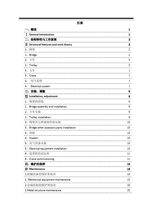
目录一、概述 1 Ⅰ. General Introduction 1 二、结构特性与工作原理 2 Ⅱ. Structural features and work theory 2 1、桥架 21、Bridge 22、小车 32、Trolley 33、大车 43、Crane 44、电气系统 44、Electrical system 4三、安装、调整9 Ⅲ. Installation, adjustment 9 1、桥架的拼装91、Bridge assembly and installation 92、小车安装92、Trolley installation 93、桥架其它附属部件的安装103、Bridge other accessory parts installation 104、检验104、Inspect 105、电气设备安装105、Electrical equipment installation 106、起重机的试运转116、Crane commissioning. 11四、维护的保养15 Ⅳ. Maintenance 15 1.机械设备的维护和保养151. Mechanical equipment maintenance 152.金属结构的维护和保养20 2.Metal structure maintenance 20Ⅰ. General IntroductionLH型电动葫芦桥式起重机(简称起重机)系列是以固定式的钢丝绳电动葫芦作为起重机(主钩和副钩)。
安装在双轨小车上,与双梁桥架配套使用的起重机。
LH type E.O.T. Crane with electric hoist (shortly termed as E.O.T.)Series use fixed wire rope electric hoist as lifting mechanism (Main hook and Auxiliary hook). Fixed on bi-rail trolley, fitted with double girder bridge .本产品适用于机械制造车间、仓库、料场、水电站检修、装配待场所,进行一般吊重装卸作业,本产品的工作环境温度为-25℃~+45℃,不适用于爆炸危险、火灾危险介质中和相对温度大于85%,充满腐蚀性气体的场所,也不使用于吊运熔化金属和有毒、易燃、易爆的物品。
数码机打印机WD250用户手册
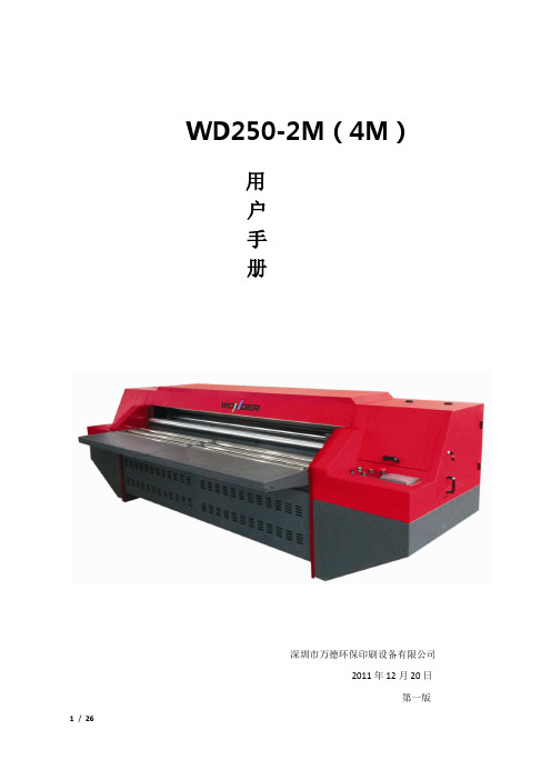
WD250-2M(4M)用户手册深圳市万德环保印刷设备有限公司2011年12月20日第一版责任与版权声明目录第一章简介------------------------------------------------------04一、电源要求----------------------------------------------04二、操作注意事项----------------------------------------04三、安装位置及使用环境注意事项-------------------04四、墨水摆放及使用注意事项-------------------------05五、性能参数表-------------------------------------------05第二章机器控制面板介绍--------------------------------------06一、机器外观------------------------------------------------06二、触控屏操作说明---------------------------------------06 第三章打印软件介绍--------------------------------------------09一、软件的安装---------------------------------------------09二、界面说明------------------------------------------------141 软件打开------------------------------------------------142 工具栏-------------------------------------------------153 状态栏--------------------------------------------------174 打印作业信息栏----------------------------------------175 参数设置------------------------------------------------186工程师管理------------------------------------------------23第一章简介感谢您购买本产品!本手册可以帮助您迅速地了解并使用此产品。
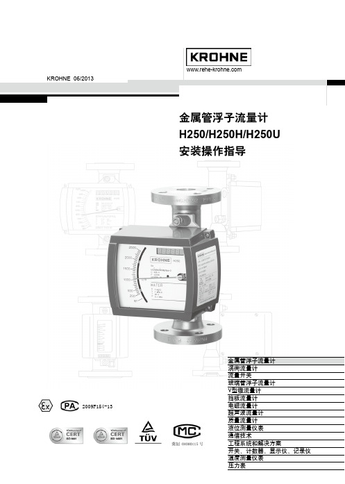
H250[说明书]
![H250[说明书]](https://img.taocdn.com/s3/m/73cf90255a8102d276a22fba.png)
不锈钢指示器机壳
M40结构图
测量管
M40 铸铝/不锈钢机壳
限位开关K1/K2
M40 指示器
刻度盘
ESK4变送器
刻度盘
FF/Profibus总线模块
ESK-Z累计显示
3
H250
2. 优点
● 坚固、简洁、可靠设计 ● 模块化、智能化指示器设计 ● 与国际市场同步,选用新型ESK变送器 ● 一次成型测量锥管 ● 陶瓷气阻尼装置 ● X-射线探伤 ● 低压力损失设计 ● 短行程、小型结构、250mm高
标准型 仪表口径 食品型 特殊型 标准型 压力等级 食品型 特殊型或按照用户要求 标准型 法兰标准 食品型 特殊型 标准型 仪表高度 特殊型 夹套连接 (选项) 标准型 特殊型
DN15-DN100 DN15-DN100 DN15-DN300 DN15-DN50/PN4.0 MPa;DN80-DN100/PN1.6MPa DN15-DN25/PN4.0 MPa;DN50-DN100/PN2.5MPa DN15-DN25/PN42.0 MPa;DN50-DN100/PN16 MPa DIN2501;ANSI; HG20592;SH3406;GB SMS;DIN11851;Tri-Clamp 按照用户要求,或用户提供 250 mm(3"-4"ANSI300lb时,高度:300mm) 300 mm或按照用户要求 DN15/PN4.0MPa 或1/2“ANSI150lb 或Φ12mm套管 按照用户要求
指示器 主要功能 流量显示 累计显示 双介质刻度 开关量(数量) 脉冲输出 4-20mA信号 HART PROFIBUS-PA总线 电缆接口 防爆形式 ● ● ● M9 指针 ● ●
信号输出电缆接口可以根据用户要求,如:1/2"NPT
全自动玻璃丝印机使用说明书

项目
零件名称
项目
零件名称
1
内波纹手柄
6
网框
2
内波纹手柄
7
气缸
3
微调组件
8
齿轮
4
五星手柄
9
齿条
5
气缸
10
第8页 地址:深圳市宝安区福永稔田工业区 79 栋 电话:0755-29501260/1560 传真:0755-29501250 网址:
精益求精不断创新 深圳全通网印机电设备有限公 TY-GL2030 全自动玻璃丝印机使用说明书
±15 35 ±0.1 930+20 100-150pcs/h 10kw/380v 12200×2800×1700 约 3500kg
1-5 工具附件:
机型
项目
规格
数量
项目
规格
数量
TY-GL2030A
机械式 刮刀
机械式回 墨刀
通用配附工具:
序号
名称规格
数量
单位
备注
1
工具箱
1
个
2
活动扳手 10"
1
把
3
内六角板手 M1.5-M10
气缸 万向手柄
气缸
项目 5 6 7 8
零件名称 节流阀 夹持组件 调节组件
第6页 地址:深圳市宝安区福永稔田工业区 79 栋 电话:0755-29501260/1560 传真:0755-29501250 网址:
精益求精不断创新 深圳全通网印机电设备有限公 TY-GL2030 全自动玻璃丝印机使用说明书
联络方式
地址:中国深圳宝安国际机场福永稔田工业区 79 栋 邮编:518103
克罗尼流量计说明书
在M9指示器中,随着磁铁的转动被直接传送到刻度盘上。
4
H250安装操作指导
A W
N
S
G
S
N
G=A+W
1. H250流量计的安装
特别提示: 仪表安装操作之前,必须将管道内的焊渣清洗干净!
M9指示器附加部件
9 限位开关Kmin, Kmax, k2 概述.............................. 21
9.1 电气连接 ......................... 21 9.2 限位点设置....................... 22 9.3 限位开关K的确定 ............... 23 9.4 技术参数 ......................... 23 10 电信号输出ESK2A(HARTTM)
1.1 安装要求 系统的实际操作压力不能超过订单中指定的操作压力。测量管法兰上用钢字打印的额定
压力不一定与检测压力相等(参见订货文件或仪表有关说明)。 ■ 确保打湿部件(测量部件)的材质适用于被测介质(参见第12页)。 ■ 环境温度和介质温度不能超过指定的最大值(参见第13页,技术参数)。 ■ 变面积流量计必须垂直安装在管道上(浮子测量原理,流向:向上)。 ■ 流量计法兰的公称尺寸应与管道的尺寸一致。 ■ 为防止管道张力,配对法兰必须与管道轴向对中并且相互平行。 ■ 水平流量计安装时应使度盘表面垂直于地面, 介质流向为流量增加时指针摆动方向。
15 40 1/2″ 150/300 25 40 1″ 150/300 50 40 2″ 150/300 80 16 3″ 150/300 100 16 4″ 150/300 10Nm~1.0Kpm~7.23ft.lbf
全自动曲面丝印机说明书(精)
20--年5月摘要本课题来源于机械工程学院与东莞腾威印刷机械有限公司的产学研究项目,主要工作之一就是为企业完成全自动曲面丝网印刷机等设备的二维、三维设计图纸,大部分工作都是在企业进行的。
本文设计主要完成印刷机构及其主传动系统部分的设计,印刷机构的设计可细分为网版的往复运动机构设计,承印物的回转运动机构设计,以及承印物的夹紧机构设计和自动传送机构设计。
往复运动采用的是曲柄摇杆机构,以滑块为载体,实现网版的往复运动;回转运动选用的是齿轮齿条机构,将滑块的往复运动转化成回转运动,实现了网版和承印物的配合运动,简化了机构。
夹紧机构采用的气缸装置,由可编程控制器控制,实现自动对位、无瓶不印等控制功能。
自动传送机构的设计采用的是曲柄摇杆设计,实现一定角度的回转摆动运动,因而带动承印物的同步传送。
本设计对印刷装置的工作原理作了详细的介绍,并通过设计计算确定其主要参数和结构。
通过对印刷装置的各部件零件做详细的测绘,完成了整机的三维总装图和各部件装配图的绘制。
关键词:丝网印刷,机构设计,全自动ABSTRACTThis subject comes from the research project of Mechanical Engineering College and Dongguan TengWei Printing Machinery Company .One of its main jobs is to finish the design drawning with two-dimension and three-dimension for the Full Automatic Screen Printing Machine for Curved Surface . Most of the above work had done in this company .The design in this paper mainly is to complete the design of Printing Instruction and its part of Main Transmission System . And the Printing Instruction has been divided into Reciprocating Motion Mechanical Design of Screen Frame , Rotary Motion MechanicalDesign of Printing Workpiece , Fixture Mechanical Design of Printing Workpiece and Automatic Conveying Mechanidal design . Reciprocation Motion adopts the Crank Rocker Mechanical Design , with the Silder as the carrier , so as to make the Screen Frame move back and forth ; Rotary Motion adopts the Gear Rock Mechanical Design , chaging the Reciprocation Motion into the Rotary Motion ,so as to achieve the Matching Movement of Screen Frame and Printing Workpiece , which simplifies the Mechanical Industruction . The Fixture Mechanical Design uses the Air Cylinder Equipment , being cotrolled by the PLC , so as to obtain the controlling function of Automatic Counterpoint and No Bottles No Printing . Automatic Conveying Mechanidal Design uses the design of Crank Rocker , achiving the goal of a certain degree of Rotary Motion at ,so as to push the Synchronous Transmission of printing workpiece . This design gives the detailed introduction for working principle of printing equipment . Via design and count , we can confirm its main parameter and instruction . We finish the whole assembly drawing with there-dimension for the whole machine and the assembly drawing for different parts through surveying and drawing in detail for different parts of assembly drawing .Keywords: screen printing, mechanism design, fully aut目录第1章绪论 (11.1 选题的背景、目的及意义 (11.1.1丝网印刷简介 (11.1.2我国丝网印刷行业的发展前景 (11.1.3本课题研究的目的和意义 (21.2 丝网印刷的组成和特点 (31.2.1全自动曲面丝网印刷的组成 (31.2.2丝网印刷的特点 (41.3 主要研究内容及思路 (51.4 预期研究结果 (7第2章印刷部分的总方案设计 (82.1 全自动曲面丝印机的参数 (92.2 全自动曲面丝印机的介绍 (92.2.1丝网印刷的工作原理 (92.2.2全自动曲面丝印机的系统组成 (10 2.3 印刷装置的总方案设计 (112.3.1印刷装置的组成 (112.3.2印刷装置的工作分析 (112.3.3印刷水平往复运动机构方案设计 (12 2.3.4印刷回转运动方案设计 (152.4 传送装置的方案设计 (172.4.1传送装置的组成 (172.4.2传送装置的工作分析 (172.4.3传送送装置的方案设计 (17第3章印刷装置的总体布局 (183.1 承印物的选型 (183.2 支撑机构的设计 (193.2.1支撑机构的功能要求 (193.2.2支撑机构的支撑形式 (203.3 印刷装置的总体布局 (203.4 传动机构的选型 (213.5 主传动系统的选型及计算 (223.5.1确定电动机的型号 (223.5.2初步确定传动比 (233.5.3带传动型号的选择 (243.6 减速器的型号的确定 (24第4章丝印机构的设计 (254.1 印刷回转运动机构设计 (264.1.1选定齿轮类型,精度等级,材料及齿数 (26 4.1.2按齿面接触强度计算 (264.1.3计算 (274.1.4按齿根弯曲强度设计 (284.1.5几何尺寸计算 (294.1.6齿条参数的确定 (294.1.7齿轮齿条设计的总结 (294.2 印刷水平往复运动机构的设计 (30 4.3 印刷传送回转运动机构的设计 (30 第5章浮动樽座的设计 (315.1 浮动樽座的总体布局 (325.2 浮动樽座的方案设计 (325.3 浮动樽座的零件设计 (32第6章执行机构的设计 (336.1 执行机构的操作调整 (336.2 刮墨板的选型 (346.3 网臂的设计 (366.4 螺纹连接的设计 (376.5 上落樽的设计 (376.6 导向机构的设计 (386.7 印刮架的设计 (40结语 (41参考文献 (43致谢 (44附录 (44第1章绪论1.1 选题的背景、目的及意义1.1.1丝网印刷简介丝网印刷在我国的历史悠久,它起源于我国秦汉时期的夹缬印花法,距今已有2000多年的历史,我国现代丝网印刷是进入80年代后,随着改革开放而不断深入发展起来的一门新兴技术。
丝印机操作说明书

(一)YTX-PV1200丝印机操作规范丝网印刷工艺流程:上料-----背电极印刷-----烘干-----背电场印刷-----烘干-----正电极印刷-----烧结-----下料一、 开启机器1、开机之前检查电源、气源是否正常,清理机器上的物品及杂物,然后按下电源按钮开启机器。
同时开启烤箱加热开关是烤箱升温到设定温度。
2、机器开启后,确保无人员在机器运动部件运动范围内活动。
按下原点复位按钮,启动机器回到原点待机位置。
二、 印刷准备1、调好各项印刷参数2、将装载待印刷硅片的花篮,正确放到6工位发料机搭载台上。
3、正确安装固定对应工序的网版、回墨刀、刮刀。
4、硅片和丝网对位,使图案在硅片中心。
(先对背电场在用背电场的图案对背电极)5、在网版上加适量的酱料。
6、以上工作完成后按自动模式,按启动按钮使机器自动运行。
三、 设备异常处理及紧急情况处理1、设备在自动运行中发生异常,机器会自动停止,同时报警并显示异常信息,操作人员根据异常信息查找异常原因排除故障,按复位按钮清除异常,按启动按钮启动机器自动运行。
如果无法排除故障及时通知设备维护工程师到现场处理。
2、设备在自动运行中对人身、产品、机器照成危害时,请立即按下紧急停止按钮,使机器立刻停止。
确保人身、产品、机器安全后,再解除紧急停止按钮,按原点复位按钮,使机器回到原点待机位置,按自动模式,按启动按钮机器自动运行。
四、 停止、关机1、设备在自动运行中按下停止按钮,机器完成一个循环动作自动停止,再次按启动按钮,恢复自动运行。
2、机器在使用完后先检查生产的产品是否生产流完,按下停止按钮,卸掉刮刀、回墨刀。
回收剩余的酱料,清洗刮刀、回墨刀、丝网,盖好所有机器盖子、门再把电源按钮按下关闭机器。
五、 注意事项1、发料机旋转台在旋转过程中,请勿取放花篮。
2、印刷头开启和关闭必须一只手按住停止按钮,另一只手按人机上的“印刷头开”按钮以防夹伤手。
3、设备在自动运行中禁止设定任何参数,必须按停止按钮使设备处于停止状态才能进行参数设定。
港龙全自动丝印机操作说明

港龙全自动丝印机操作说明
全自动丝印机的操作说明:
1、开启全自动丝印机操作面板上的电源开关,触摸式液晶屏开始工作。
同时将丝印网板放入手臂钢板座内,并用旋钮轻微固定,便于丝印网板的后续调整。
2、如果第一次印白纸先开单次,先同时按匀墨一匀墨刀两个按键,网框外走,再同时按刮墨和刮墨刀两个键,网框内走,反复几次直到左右手两个电眼检测到印刷材料边缘,电眼灯同时亮起:其次按启动印刷,印两张以后停下测量,印刷的长度与设定长度是否一致,确认后把前电眼调到色标,印刷方式打到套印按启动开始印刷。
3、为了便于生产,缩短对网版的时间,提高生产效率,班长在安排全自动丝网印刷机生产时,一般会安排两个主操协作生产,在操作设备按钮的主操在操作设备之前,首先必须要确认另一主操不在丝印机上或肢体未接触丝印机方可进行按钮操作。
全自动丝印机的操作说明大家都熟悉了吗?丝印机在操作时首要注意好操作的安全防范,除了制造厂家本身的技术安全防护外,现场丝印机生产操作人员也要按照正确的操作步骤工作,减少安全事故发生的机率,正确的操作方法会大大降低安全事故的发生。
SITRANS LG250操作说明书

制导雷达SITRANS LG250 Foundation Fieldbus棒型和绳型探头操作说明书 • 09/20172PBD-51041258SITRANS LG250 - 操作说明书44572-ZH-1710303PBD-51041258SITRANS LG250 - 操作说明书44572-Z H -171030目录1关于本文献资料 ............................................................................................................................................51.1 功能 .............................................................................................................................................................................51.2 对象 .............................................................................................................................................................................51.3 使用的标记.. (52)为了您的安全 ...............................................................................................................................................62.1 获得授权的人员.........................................................................................................................................................62.2 合规使用 .....................................................................................................................................................................62.3 谨防错误使用.............................................................................................................................................................62.4 一般安全提示.............................................................................................................................................................62.5 欧盟一致性.................................................................................................................................................................62.6 NAMUR 推荐 ............................................................................................................................................................62.7 在美国和加拿大进行安装和运行. (73)产品说明 ......................................................................................................................................................83.1 结构 .............................................................................................................................................................................83.2 作业方式 .....................................................................................................................................................................93.3 包装、运输和仓储 ..................................................................................................................................................103.4 附件与备件 (114)安装 ...........................................................................................................................................................124.1 一般提示 ...................................................................................................................................................................124.2 安装提示 . (125)与供电装置相连接 ......................................................................................................................................205.1 准备接线 ...................................................................................................................................................................205.2 连接 ...........................................................................................................................................................................205.3 单腔式外壳的接线图 ..............................................................................................................................................225.4 双腔式外壳的接线图 ..............................................................................................................................................225.5 启动阶段 . (236)用显示和调整模块进行调试 ........................................................................................................................246.1 使用显示和调整模块 ..............................................................................................................................................246.2 操作系统 ...................................................................................................................................................................256.3 参数化 - 快速调试 ..................................................................................................................................................266.4 参数化 - 扩展了的操作功能..................................................................................................................................266.5 对设置的参数数据的存储 .. (387)用 PACTware 进行调试 .............................................................................................................................407.1 连接计算机...............................................................................................................................................................407.2 通过 PACTware 设置参数.....................................................................................................................................407.3 通过快速调试来投入使用 ......................................................................................................................................417.4 对设置的参数数据的存储 .. (428)用其它系统进行调试 ...................................................................................................................................438.1 DD 操作程序............................................................................................................................................................438.2 Field Communicator 375, 475 . (439)诊断与服务 .................................................................................................................................................449.1 维护 ...........................................................................................................................................................................449.2 诊断储存器...............................................................................................................................................................449.3 状态信息 ...................................................................................................................................................................449.4 排除故障 ...................................................................................................................................................................479.5 更换电子插件...........................................................................................................................................................519.6 更换测量绳/测量棒.................................................................................................................................................519.7 软件升级 ...................................................................................................................................................................539.8 需要维修时的步骤 .. (53)10 拆卸 (54)4PBD-51041258SITRANS LG250 - 操作说明书44572-ZH-17103010.1 拆卸步骤 ...................................................................................................................................................................5410.2 废物清除 ...................................................................................................................................................................5411 附件 .. (55)11.1 技术参数 ...................................................................................................................................................................5511.2 基金会现场总线附加信息 ......................................................................................................................................6711.3 尺寸 ...........................................................................................................................................................................7511.4 商标 (80)用于防爆区域的安全提示请在将仪表用于防爆应用领域时遵守专门针对防爆的安全说明。
全自动单色丝印机使用说明书20140906

全自动单色丝印机使用说明机器示意图目录1.安全注意事项…………………………………………………………P.31-1人身安全…………………………………………………………P.31-2机械安全…………………………………………………………P.32.应用及规格……………………………………………………………P.42-1应用………………………………………………………………P.42-2规格………………………………………………………………P.43.安装及调校……………………………………………………………P.53-1安装………………………………………………………………P.53-2机械调整(图)…………………………………………………P.6(1)传递摆角的调整………………………………………………P.6(2)丝印摆角的调整………………………………………………P.6(3)传瓶调整………………………………………………………P.7(4)印刷定位………………………………………………………P.7(5)火焰处理………………………………………………………P.7(6)火焰处理………………………………………………………P.74.主控台及控制部件……………………………………………………P.84-1电源总开关………………………………………………………P.84-2 控制台……………………………………………………………P.94-3 气动调解阀控制面板……………………………………………P.10 4-4 触摸屏操作指南…………………………………………………P.12-205.操作指导………………………………………………………………P.216.维护及保养………………………………………………………P.221. 安全注意事项:操作丝印机应特别注意人身和机械安全,重点列出如下:1-1.人身安全1、眼睛的防护(1)在UV灯点亮情况下,切勿打开机罩,在必要情况下则须戴上UV安全眼镜,避免紫外线对眼睛的伤害。
Chemtrol CH250 说明书
说明书的2.05型号具有可编程、可显示和安全保护功能。
2.02及其以下版本不支持可显示功能。
显示功能可以直观的控制加药量和流量安全控制阀。
CH250的出厂预设置如下:PH值调整为加入酸液,杀菌消毒剂添加与PH 值锁定,流量安全控制阀设定为开。
若修改预设置情阅读下面的说明书。
1)PH值的调整当按下PH按钮时,显示器会显示acid或base,使用up(加)或down(减)改变设置。
调整完毕按PH键保存设置。
2)锁定设置锁定保护启动,当PH值进入报警状态的时候,消毒剂也不再添加。
{L1}表示锁定启动,使用up和down键转换{L1}和{L0},{L0}意味着消毒剂添加和PH值调整完全独立工作。
3)流量安全控制阀设置{F1}是出厂预设置,此时安全控制阀开。
使用up和down键转换{F1}和{F0}。
注意:在没有任何报警的情况下,加药泵不能正常工作,检查此设置。
CH250/255终端模块交流电压输入输出LINE 1……………………黑(火线)LINE 2……………………白(零线)GROUND…………………绿(地线)终端模块流量安全控制阀……………………TB2-1 (+5v) 红线(paddle wheel flow switch) TB2-2 白线TB2-3 黑线流量阀……………………………… TB2-4 信号干连接方式(flow switch) TB2-5 地线报警终端模块报警的预设置为hot,JP6是报警终端模块的跳线,JP在{1-2},{3-4}位置是hot,干方式需跳线在{2-4}位置。
保险丝配置F1+F2 5A 加消毒剂泵F3+F4 5A 加酸泵F5+F6 5A 警报F7 25A 交流电输入Chemtrol CH250是数字监控游泳池、水塔和SPA等的PH值和消毒液浓度的装置。
该系列有4种型号:· Chemtrol 255 支持PPM/PH · Chemtrol 250 支持ORP/PH · Chemtrol 240 支持PH· Chemtrol 230 支持ORP游离氯如图1,Cl2在水中水解为两种粒子·HClO 分子强杀菌氧化剂·Cl-离子弱杀菌氧化剂在PH值为7.5的时候,HClO和Cl-各占50%。
丝印机操作说明书

(一)YTX-PV1200丝印机操作规范丝网印刷工艺流程:上料-----背电极印刷-----烘干-----背电场印刷-----烘干-----正电极印刷-----烧结-----下料一、 开启机器1、开机之前检查电源、气源是否正常,清理机器上的物品及杂物,然后按下电源按钮开启机器。
同时开启烤箱加热开关是烤箱升温到设定温度。
2、机器开启后,确保无人员在机器运动部件运动范围内活动。
按下原点复位按钮,启动机器回到原点待机位置。
二、 印刷准备1、调好各项印刷参数2、将装载待印刷硅片的花篮,正确放到6工位发料机搭载台上。
3、正确安装固定对应工序的网版、回墨刀、刮刀。
4、硅片和丝网对位,使图案在硅片中心。
(先对背电场在用背电场的图案对背电极)5、在网版上加适量的酱料。
6、以上工作完成后按自动模式,按启动按钮使机器自动运行。
三、 设备异常处理及紧急情况处理1、设备在自动运行中发生异常,机器会自动停止,同时报警并显示异常信息,操作人员根据异常信息查找异常原因排除故障,按复位按钮清除异常,按启动按钮启动机器自动运行。
如果无法排除故障及时通知设备维护工程师到现场处理。
2、设备在自动运行中对人身、产品、机器照成危害时,请立即按下紧急停止按钮,使机器立刻停止。
确保人身、产品、机器安全后,再解除紧急停止按钮,按原点复位按钮,使机器回到原点待机位置,按自动模式,按启动按钮机器自动运行。
四、 停止、关机1、设备在自动运行中按下停止按钮,机器完成一个循环动作自动停止,再次按启动按钮,恢复自动运行。
2、机器在使用完后先检查生产的产品是否生产流完,按下停止按钮,卸掉刮刀、回墨刀。
回收剩余的酱料,清洗刮刀、回墨刀、丝网,盖好所有机器盖子、门再把电源按钮按下关闭机器。
五、 注意事项1、发料机旋转台在旋转过程中,请勿取放花篮。
2、印刷头开启和关闭必须一只手按住停止按钮,另一只手按人机上的“印刷头开”按钮以防夹伤手。
3、设备在自动运行中禁止设定任何参数,必须按停止按钮使设备处于停止状态才能进行参数设定。
CASIO UP-250 外部打印机维护手册说明书

EXTERNAL PRINTERFEB . 2000MODEL UP-250Casio UP-250 external printer service ManualCONFIDENTIALITY AGREEMENTBY USING THIS DOCUMENT, YOU AGREE TO ABIDE BY THE TERMS OF THIS AGREEMENT. PLEASE RETURN THIS DOCUMENT IMMEDIATELY IF YOU DO NOT AGREE TO THESE TERMS.1.This document contains confidential, proprietary information of CASIO or its affiliates.You must keep such information confidential. If the user is a business entity or organization,you must limit disclosure to those of your employees, agents and contractors who havea need to know and who are also bound by obligations of confidentiality.2.On the earlier of (a) termination of your relationship with CASIO, or (b) CASIO’s request,you must stop using the confidential information. You must then return or destroy theinformation, as directed by CASIO.3.If a court, arbitrator, government agency or the like orders you to disclose any confidentialinformation, you must immediately notify CASIO. You agree to give CASIO reasonablecooperation and assistance in resisting disclosure.4.You may use confidential information only for the purpose of operating or servicing theproducts to which the document relates, unless you obtain the prior written consent of CASIOfor some other use.5.CASIO warrants that it has the right to disclose the confidential information.CASIO MAKES NO OTHER WARRANTIES CONCERNING THE CONFIDENTIALINFORMATION OR ANY OTHER INFORMATION IN THE DOCUMENT, INCLUDING(WITHOUT LIMITATION) ANY WARRANTY OF TITLE OR NON-INFRINGEMENT.CASIO has no liability for loss or damage arising from or relating to your use of orreliance on the information on the document.6.You may not reproduce, store or transmit the confidential information in any form or by anymeans (electronic, mechanical, photocopying, recording, or otherwise) without the priorwritten permission of CASIO.7.Your obligations under this Agreement are in addition to any other legal obligations.CASIO does not waive any right under this Agreement by failing to exercise it. The laws ofJapan apply to this Agreement.FCC CLASS AFCC Compliance StatementFor American UsersThis equipment has been tested and found to comply with the limits for a Class A digital device, pursuant to Part 15 of the FCC Rules. These limits are designed to provide reasonable protection against harmful interference when the equipment is operated in a commercial environment.This equipment generates, uses, and can radiate radio frequency energy and, if not installed and used in accordance with the instruction manual, may cause harmful interference to radio communications. Operation of this equipment in a residential area is likely to cause harmful interference, in which case the user will be required to correct the interferenceat his or her own expense.WARNINGThe connection of a non-shielded printer interface cable to this printer will invalidate the FCC Verification of this device and may cause interference levels which exceed the limits established by the FCC for this equipment.You are cautioned that changes or modifications not expressly approved by the party responsible for compliance could void your authority to operate the equipment.FOR CANADIAN USERSThis Class A digital apparatus meets all requirements of the Canadian Interference-Causing Equipment Regulations.Cet appareil numérique de la classe A respecte toutes les exigences du Règlement sur le matériel brouilleur du Canada. GEREÄUSCHPEGELGemäß der Dritten Verordrung zum Gerätesicherheitsgecsetz (Maschinenlärminformations- Verordnung-3. GSGV) ist der arbeitsplatzbezogene Geräusch-Emissionswert kleiner als 70 dB(A) (basierend auf ISO 7779).IntroductionPU-250 Series (Type B) printers are one-station printers for ECR and POS use that can print the results of weighing or measuring. The main features of the PU-250 Series (Type B) printers are the following:High-speed printing through logic-seeking controlExcellent reliability and long life resulting from the use of two stepping motors, one for moving the carriage and one for paper feedingFlexible paper feed setting permits printing in accordance with any user-defined formatCommand protocol based on ESC/POS, a widely used standardBuilt-in drawer kick-out interface provides capability to drive two drawersSelectable character fonts (7 x 9, 9 x 9)Semi-automatic paper loading capabilityAC adapter (included) provides compact power supplyCompact and light in weightAutomatic Status Back (ASB) function to automatically send printer status changesAuto-cutter euippedTwo-color printing: black and red are selectable.Notes and CautionsNote:Notes have important information and useful tips on the operation of your printer.CAUTION:Cautions must be observed to avoid damage to your equipment.CONTENTSChapter 1Features and General Specifications (1)Features (2)Printing Specifications (2)Character Specifications (3)Paper (4)Auto-cutter (5)Paper Roll Supply Device (5)Receive Buffer (5)Electrical Specifications (5)Ribbon Cassette (5)External Dimensions and Weight (6)Environmental Specifications (6)Reliability (7)Safety Standards (7)Printer Installation Position (7)Hardware Configuration (8)Main Unit Specifications (9)Paper Feed Motor (9)Carriage Motor (9)Print Head Unit (9)Home Position Sensor (9)Paper End Detector (10)Paper Roll Near-end Detector (Optional) (10)Connectors (10)Interface Connector (10)Power Supply Connector (11)Drawer Kick-Out Connector (11)Interface (13)RS-232 Serial Interface (13)RS-485 Serial Interface (option) (16)IEEE 1284 Parallel Interface (16)Buttons and Switches (19)Power Switch (19)Panel Button (19)DIP Switches (20)Panel LEDs (22)Self-test (22)Error Processing (23)Printer Operation When an Error Occurs (23)Data Receive Error (23)Buffer Full Printing (23)Detectors and Printing (23)Hexadecimal Dump (24)Performing a Hexadecimal Dump (24)Options (24)External Power Supply PS-170 (25)Chapter 2Mechanism Configuration and Operating Principles (26)Printer Mechanism Operating Principles (26)Print mechanism unit (27)Print head unit movement (28)Wire movement when a single dot is printed (28)Printing a character (9x9 font) (29)Paper Feed Mechanism Unit (30)Paper loading (semi-automatic loading) (31)Paper feeding (31)Ribbon Feed Mechanism Unit (32)Ribbon feeding (33)Detection Mechanism Unit (34)Home position detection mechanism (34)Paper detection mechanism (35)Paper roll near-end detection mechanism (optional) (35)Auto-cutter mechanism (35)Ribbon Switch Mechanism Unit (36)Switching from Black to Red (36)Releasing from Red to Black (36)Electrical Circuitry Operating Principles (37)Hardware Configuration (37)Principles of Operation (41)Power Supply Circuitry (41)Control Circuitry (42)CPU (43)Various detector circuits (46)Host interface circuit (47)Drawer kick-out drive circuit (47)DIP switch read circuit (48)Printer Mechanism Driver Circuits (50)Print head driver circuit (50)Paper feed motor driver circuit (51)Carriage motor driver circuit (51)Auto-cutter driver circuit (52)Chapter 3Handling and Maintenance (53)Handling Precautions (53)Storage Precautions (53)Use Precautions (53)Paper Handling Precautions (53)Ribbon Cassette Handling Precautions (54)Replacing the Paper Roll (54)Replacing the Ribbon Cassette (57)Removing Jammed Paper (60)Using the Power Switch Cover (64)Inspection and Maintenance (65)Cleaning (66)Lubricants (66)Lubrication Points (67)Tool List (67)Chapter 4Troubleshooting (68)Self-test (68)Initiating the Self-test (68)Self-test Standby (68)Ending the Self-test (68)Troubleshooting Flowchart (69)Troubleshooting Tables (76)Error Types and Countermeasures (82)Chapter 5Disassembly, Assembly, and Adjustment (87)Small Part Specifications (87)Disassembly (88)Removing the fuse (88)Removing the print head unit (89)Removing the auto-cutter (91)Removing the main circuit board assembly (92)Sub-assembly A (94)Paper feed frame unit assembly (94)Main Assembly 1 (98)Ribbon switch lever, ribbon release spring, ribbon release lever,ribbon intermediate gear, ribbon transmission gear, ribbon take-up assembly,and ribbon drive plate assembly (98)Main Assembly 2 (100)Tension plate assembly (100)Main Assembly 3 (100)Paper feed frame assembly (100)Main Assembly 4 (101)Carriage motor assembly (101)Main Assembly 5 (102)Carriage sub assembly (102)Main Assembly 6 (103)Carriage shaft assembly (103)Main Assembly 7 (104)Adjustment roller shaft holder assembly (104)Main Assembly 8 (105)Carriage guide shaft assembly (105)Main Assembly 9 (105)Belt tension spring assembly (105)Main Assembly 11 (108)Carriage motor heat sink assembly (108)Main Assembly 12 (108)Print head FPC assembly (108)Main Assembly 13 (110)Print head unit (110)Main assembly 14 (111)Left cover fixing plate and right cover fixing plate (111)Main Assembly 15 (112)Ribbon frame earth plate (112)Main Assembly 16 (113)Ribbon frame assembly, ribbon frame spring, and ribbon frame fixing plate (113)Main Assembly 17 (114)Thumb-screw and head cover (114)Main Assembly 1 (Case Unit) (115)Lower cutter plate assembly (115)Main Assembly 2 (Case Unit) (116)Upper plate assembly (116)Main Assembly 3 (Case Unit) (118)Main circuit board assembly (118)Main Assembly 4 (Case Unit) (119)Inserting the cables (119)Main Assembly 5 (Case Unit) (120)Lower case assembly (120)Main Assembly 6 (Case Unit) (121)Manual cutter assembly and auto-cutter fixing plate (121)Main Assembly 7 (Case Unit) (123)Auto-cutter assembly (123)Main Assembly 8 (Case Unit) (126)Paper roll receive rollers, upper case, guide roller, and switch panel assemblies (126)Main Assembly 9 (Case Unit) (128)Interface circuit board assembly and connector plate (128)Main Assembly 10 (Case Unit) (130)Lower plate, ROM cover, and rubber foot assembly (130)Main Assembly 11 (Case Unit) (131)Main cover assembly (131)Main Assembly 12 (Case Unit) (132)Near-end detector assembly (optional) (132)Adjustment (134)Platen gap adjustment (134)Appendix (135)RS-485 Serial Interface (135)Main Circuit Board Parts Layout (140)RS-232 Serial Interface Circuit Board Parts Layout (141)IEEE 1284 Parallel Interface Circuit Board Parts Layout (142)RS-485 Serial Interface Circuit Board Parts Layout (143)Main Circuit Board Diagram (144)RS-232 Serial Interface Circuit Board Diagram (145)IEEE 1284 Parallel Interface Circuit Board Diagram (146)RS-485 Serial Interface Circuit Board Diagram (147)Printer Mechanism Unit Overall Exploded Diagram (148)Case Unit Overall Exploded Diagram (149)Printer Mechanism Unit Lubrication Points Diagram (150)Case Unit Lubrication Points Diagram (151)Parts List (152)EXPLODED DIAGRAM FOR TM-U200B/U210B NO.1 (154)EXPLODED DIAGRAM FOR TM-U200B/U200PB/U210B/U210PB NO.2 (155)。
Precision Products Inc. HC250 水管滚动车辆说明书

Caution: Read all Safety Instructions and Operating Instructions Carefully.Manual Contents Safety Instructions Assembly Operation Maintenance Parts Warranty24-5 55 6-7 8Your New Hose Reel CartCongratulations on your purchase of a new Precision Products Inc. Hose Reel. Your cart hasbeen engineered and built to give you the most dependable and best performing product possible.If you experience any problem you can not easily resolve, please feel free to contact our knowledgeable and helpful customer service department toll-free at1 (800) 225-5891.3/17Rules for Safe OperationThe following safety precautions are suggested. This Hose Reel Cart is designed, engineered and tested to offerreasonably safe and effective service, provided that it is operated in strict accordance with these instructions. Failure to do so may result in personal injury. Always observe the rules of safe operation. Please read and retain this manual.∙Be alert for holes in the terrain and other hazards.∙Follow maintenance and lubrication instructions as outlined in this manual.∙Always wear substantial footwear. Do not wear loose fitting clothing that may get caught in moving parts.Carton Contents1 Left Side Frame1 5 Basket2 Right Side Frame 1 6 Crank Handle3 Handle W/Grip17 Wheel 4Support Bracket 28 Reel RodsRef. Description QTY Ref. Description QTY Ref. Description QTY 1 1 2 4 9 Hose 1123456789Parts and SupportPlease do not return this product to the store prior to contacting PrecisionAt Precision Products Inc., our goal is to deliver quality, value and outstanding service. If for any reason our product does not meet your expectations, please contact us and we will take care of any problem you may have with this unit.When ordering replacement parts please have the model number, part description, part number, inspector number and date on carton available so that we can best serve you.Precision Products Inc.1 (800) 225-5891123546Assembly InstructionsTools Needed For Cart Assembly ( 1 ) Screwdriver( 1 ) M10 Wrench or Adjustable Wrench2. Attach Left Side Frame to Right Side Frame using four M8 Hex Nuts and tighten. See Figure 24. Attach Wheels to Frame using two M12 x 95mm and two M12 Nylock Nuts. . See Figure 4Figure 3Figure 45. Attach Storage Basket to Frame using two M8 x32mm HH Bolts and two M8 Nylock Nuts. See Figure 5Figure 5Storage BasketM8x35MM HH Bolts & M8 Nylock NutsM12 x 95mm HH Bolt & M12 Nylock Nut1. Attach four Hose Reel Tubes to Left side of the Hose Reel End with the Belt feature using four M8 Hex Nuts . See Figure 1 3. Attach Support Brackets to Left Side Frame using two M8 x 35mm bolt sets. Repeat for Right Side. See Figure 3.Support Brackets M8 x 35mmBolt Sets6. Attach Handle to Frame using two M8 x 35mm HHFigure 6FrameHandle7. Attach Coupler to Right Side Hose Reel End. See Figure 7CouplerFigure 78. Attach Handle to Handle Crank using one M8 Nylock Nut. Attach Handle Crank using Hex Bolt Flat Washer and Spring. See Figure 8OperationM8 x 35mm HH Bolt & M8 Nylock NutsFigure 8M8 NylockCrankCrank HandleSpringFlat WasherHH Bolt9. Attach Hose Lead as shown. See Figure 9Figure 910. To tighten Belt adjust the hose reel using the adjustment bolts shown in figure 10. Make sure both sides are adjusted evenly. See Figure 10.Adjustment BoltsFigure 101* Frame Left Side121314151617187 192020 21222324HC250Not All Parts ShownHose Reel CartThe limited warranty set forth below is given by PrecisionProducts, Inc. with respect to new merchandise purchased and used in the United States, its possessionsand territories.Precision Products, Inc. warranties the product(s) listedagainst defects in material and workmanship, and will at our option, repair or replace, free of charge, any part found to be defective in materials or workmanship. This limited warranty shall only apply if this product has been assembled, operated, and maintained in accordance with the owner’s manual furnished with the product, and has not been subjected to misuse, abuse, neglect, accident, improper maintenance, alteration, vandalism, theft, fire, water, or damage because of other peril or natural disaster. Normal wear parts or components thereof are subject to separate terms as follows: All normal wear parts or component failures will be covered on the product for a period of one year. Parts found to be defective within the warranty period will be replaced at our expense. Our obligation under this warranty is expressly limited to the replacement or repair, at our option, of parts found to be defective in material and workmanship.Contacting ServiceWarranty parts replacements are available, ONLY WITHPROOF OF PURCHASE, through our Customer ServiceDepartment. Call 1 (800) 225-5891This limited warranty does not provide coverage in the following cases:1. Routine maintenance items such as lubricants andfilters.2. Normal deterioration of the exterior finish due to useor exposure.3. Transportation and/or labor charges.No implied warranty, including any implied warranty ofmerchantability of fitness for a particular purpose, appliesafter the applicable period of expressed written warranty above as to the part as identified below. No other expressed warranty whether written or oral, except as mentioned above, given by any person or entity, including a dealer or retailer, with respect to any product, shall bind Precision Products, Inc. During the period of the warranty, the exclusive remedy is repair or replacement of the product as set forth above.The provisions as set forth in this warranty provide thesole and exclusive remedy arising from the sale. Precision Products Inc. Will not be liable for incidental orconsequential loss or damage including, without limitation, expenses incurred for substitute orreplacement lawn care services, or for rental expenses to temporarily replace a warranted product.Some states do not allow the exclusion of limitation of incidental or consequential damages, or limitations on how long an implied warranty lasts, so the above exclusions or limitations may not apply to you.During the warranty period, the exclusive remedy is replacement of the part. In no event shall recovery of any kind be greater than the amount of the purchase price the product sold. Alteration of safety features of the product shall void this warranty. You assume the risk and liability for loss, damage, or injury to you and your property and/or to others and their property arising from the misuse or inability to use this product.This limited warranty shall not extend to anyone other than the original purchaser or to the person for whom it was purchased as a gift.Local Law to this WarrantyThis limited warranty gives you specific legal rights, and you may also have other rights which vary from state to state.Warranty PeriodThe Warranty period stated below begins with the Proof of Purchase. Without the proof of purchase, the Warranty period begins from the date of manufacture. Hose Reel Cart Warranty PeriodThe warranty period for this unit is as follows: All parts are covered one year from the date of sale.。
LORCH焊机说明书操作手册

操作手册S SpeedPulse909.1181.3-01目录1 设备部件 (02)2 图标释义 (04)2.1 操作手册中的图标释义 (04)2.2 设备上的图标释义 (04)3 安全提示 (05)4 环境条件 (06)5 使用总则 (06)6 元件保护 (06)7 安全检查 (06)8 噪音排放 (06)9 电磁兼容性 (06)10 安装和运输 (07)11 简易操作说明 (08)12 启动前 (08)12.1 联接焊炬 (08)12.2 联接接地线 (08)12.3 固定接地夹 (09)12.4 插入焊丝卷轴 (09)12.5 装载电极丝 (09)12.6 联接保护气体 (10)12.7 添加冷却液 (10)12.8 将设备调至铝焊丝焊接 (11)13 启动 (12)13.1 控制面板 (12)13.2 电流/电压 显示 (13)13.3 远程控制焊炬 (13)13.4 二级参数...........................14 13.5 焊接模式 (14)13.6 Quatromatic (15)13.7 发火器 (15)13.8 特制 4-stroke (15)13.9 Tiptronic 参数记忆功能 (15)13.10 密码锁功能 (17)13.11 特殊功能 (17)13.12 重置设定 (17)14 菜单结构 (18)15 错误代码 (21)16 常见故障解答 (22)17 MIG / MAG 焊接方式基本原理 (23)17.1 MIG / MAG 焊接方式原理 (23)17.2 电弧类型 (23)18 脉冲弧焊接方式基本原理 (25)19 修理和维护 (27)19.1 日常检查 (27)19.2 焊炬保养 (27)20 技术参数 (28)21 图表 (30)22 可选配置 (31)23 配件 (32)24 废弃处置 (33)25 服务 (33)26 符合标准声明 (33)27 附录 (34)27.1 焊炬挂架安装说明 (34)1 设备部件图1:设备部件图2:设备部件1 焊炬2 减压阀3 气瓶4 放置顶板5 悬吊孔6 手柄7 控制面板8 插座9 进风口 10 底轮 11 主旋钮 12 电流/电压显示屏 13 接地钳 14 接地线插座 15 控制面板保护罩 21 电焊钳插座 80 WUK 5 冷却系统插座 81 LorchNet 系统插座某些描述的附件并不包含在供货范围内,可能有变动。
RIC-250 LEUCO打印机 说明书
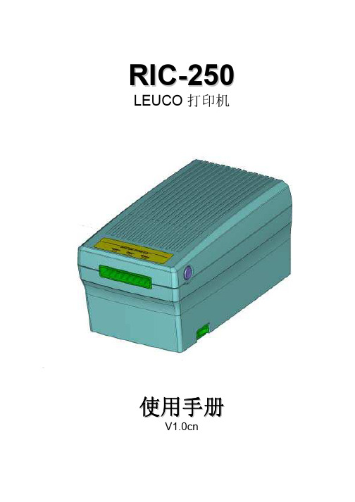
R I C-250 LEUCO 打印机使用手册V1.0cn目录1使用前的安全需知 (3)2产品简介 (4)2.1特点 (4)2.2产品包装 (4)2.3控制及连接 (4)2.4技术参数 (6)2.5卡特性 (8)3打印机安装 (9)3.1安装条件 (9)4维护保养 (10)4.1清洁辊轮 (10)4.2清洁打印头 (10)4.3更换毛刷 (12)4.4更换保险丝 (12)5尺寸 (13)5.1尺寸 (13)1 使用前的安全需知警告!将打印机放置在平坦,稳固的平面上打印机翻到或掉下时有可能砸伤人!保证良好的通风通风口是为保证打印机不会过热而设置的,堵塞通风口会引起火灾!为保证良好的通风,打印机至少离开挡风物体10厘米!请勿将除LEUCO卡之外的任何物体插入打印机请勿将除LEUCO卡之外的任何物体插入打印机,也不能将水倒入打印机。
如发生意外请立即拔除电源线!任何除LEUCO卡之外的物体进入打印机会损坏打印机引起短路甚至引发火灾!打印机在打印过程中切勿关闭电源在打印过程中关闭电源会损坏正在打印的卡片。
勿使打印机靠近水源打印机如进水会引起短路!如打印机在使用过程中出现异常请立即停止操作在使用过程中如出现异常,如冒烟,怪声等。
请立即拔除电源线。
除LEUCO卡以外的物体进入打印机会引起机器损坏,电器短路,甚至火灾。
切勿打开机盒或将打印机组件取出打开机盒或将打印机组件取出有触电危险!注意工作过程中不要触及电机和打印头电机和打印头在工作时温度很高,直接触及会发生烫伤在电源开关开启时不要插入或拔除电源线和数据线!.2 产品简介2.1 特点• 本打印机打印及擦除均通过打印头进行,因此非常节能。
• 本打印机内带有非接触卡读卡器,可对ISO14443A (Mifare )卡进行处理。
• 本打印机带有RS-232和USB 接口。
2.2 产品包装下列附件应包含在打印机的包装内: 电源线一条; 清洁包一个; 使用手册一本。
Canon Film Loader 250 说明书

It is convenient to remove . the magazine beforehand in the light because the film is loaded in a darkroom. The procedure for taking out the spool is as follows. Turn the inner case, while depressing the release button on the top side of the inner case, and align the opening sections of the outer and inner cases. The inner case and spool can then be pulled out from the top.
Taking Out t he Magaz ine Spool
? :1'-0./,,;z. :f-JCC1lllXtfJ l
Release 1W~~ ;j( :7 :,..-
How to Use the Fi lm Loader 250
7-1'J C.b.Cl -:)t' - C1lj9! l ' n
* j-; i:< x.. iT, (WIj, ::J:r./:7 7 1 it-- L )
®~ 2< ;;;:; 1.>' if, I) fi£ 0) 2< 'd,- t 0) i T 7 1 it--Li-~2<;;;:;1: t, :fmJl:iJ7..7"-it--I::-t-, < I) Jf:z it Itt:. fit, '/ ,-{ i- 7i-1~U I:: L l i:tl<,j\fi j~iJJf:z it IH ill I::
- 1、下载文档前请自行甄别文档内容的完整性,平台不提供额外的编辑、内容补充、找答案等附加服务。
- 2、"仅部分预览"的文档,不可在线预览部分如存在完整性等问题,可反馈申请退款(可完整预览的文档不适用该条件!)。
- 3、如文档侵犯您的权益,请联系客服反馈,我们会尽快为您处理(人工客服工作时间:9:00-18:30)。
LH-250丝印机中文版说明书本公司生产的LH-250丝印机,适用于直径X长度:¢70X200㎜以内曲面及长X宽:220X220㎜以内平面各类塑材的制品的丝网印刷.本机印刷速度快、效果好、能耗低、效率高,操作控制简单。
一、技术特性最大印刷尺寸(㎜)¢70×200mm曲面或20×200mm平面横向移动平均速度(pieces/min)15用气压力(Mpa)0.4—0.6电源(V/HZ)220/60外型尺寸(mm)长×宽×高800mm×480mm×1250mm机体重量(Kg)150二、控制面板各按钮功能1、功能设定:功能设定按钮是设定机器所处的工作状态的按钮。
①当工作种类显示‘ADJ’时,机器进入校机状态,此时可以调整工作台上下速度。
在‘ADJ’状态下,可通过按下‘速度/清数’键,使工作台下降印刷计数清零。
②当工作种类显示‘MAN’时机器进入单循环状态,可通过‘启动/停止’按钮或脚踏开关,每按一次完成一个工作循环。
③当工作种类显示‘AUTO’时,机器进入全自动连续印刷状态,可通过按下‘启动/停止’按钮,使机器进入全自动连续工作状况。
2、启动/停止:‘功能设定’任何一种状态下,按下按钮都可‘启动’机器或‘停止’机器运行。
3、左/右:每按一次左/右功能键,机器印头可以左右交替运动。
在印刷时,按‘启动/停止’按钮或脚踏开关,当向左运动时,会停在左边;当向右运动时,会停在右边。
(便于洗网)4、速度/清数:①当功能设定处于‘MAN‘或’AUTO‘状态下,按下按键,可以调整机器从第一个工作循环结束到第二个工作循环开始的时间间隙,速度指示VO最慢,V9最快,可在0-9范围内调整。
②当功能设定处于‘ADJ’状态时,按下键可使印刷计数清零,。
5、通气、断气:‘通气、断气’校机用的专用开关,当开关拨向‘断气’时,左右断开气源,可以用手移动网版或刮刀校机:通常情况下,开关拨向‘通气’。
6、印刮气压调节:指针指示的数值为印刮气压值。
7、印刮气压调节:通过旋钮可以调节印刮气压的大小,当向右旋时,印刮气压加大,当向左旋时,印刷气压减小。
8、左:调整网版向的移动速度。
当旋钮向左旋时,网版向左的移动速度加快,反之,当旋钮向右旋时,网板向左的移动速度减慢。
9、右:调节网版身右的移动速度。
当旋钮向右旋时,网版向右的移动的速度加快;反之当旋钮向左时,网版向右的移动速度减慢。
10、上:打开此按钮时,印刮刀上提,可以安状或卸掉网框。
11、下:打开此旋钮时,印刮刀下移,可以进入印刷状态。
12、手推式气源开关:(安装于空气过滤器的进气端)当开关向前推时,气源打开;当开关向后推时,气源关闭。
13、电源总开关:是机器与外接气源通电或断电的总开关。
三、LH-250丝印机的操作㈠开机前准备及注意事项1、整机安全检查:①机器虽经出厂检验合格,但经长途搬运,会出现螺丝松脱等情况。
因此,要对整台机器进行一次全面安全检查,确认整机安装正常,同时做好清洁卫生。
②检查电源电压是否符合本机电源电压,本机电源电压为220V,60HZ。
③检查各润滑点的润滑。
④检查系统气压是否达到本机工作要求,可从气压表上读出,工作压力必须在0.46MPa,气压不移,整机将无法工作。
2、按所需印刷图案的大小,制作一个完善的丝印网版。
3、调校好所用油墨的粘稠度。
4、按照被印件的大小和形状的需要,配备一个容易将被印件放进和取出又不容易走位的夹具及印圆柱体印件时所需之齿轮。
5、准备适量之洗网水及白布碎(细件之白布料)等,用以清洁网版及被印件。
㈡试运行开停机程序在开机前准备及注意事项确认无误后,可进入度运行。
1、打开电源总开关,(指示灯亮),打开手推式气源开关和通气阀机器送气。
2、把‘功能设定’按钮设置于‘ADJ’校机状态。
3、调节印刮气压调节旋钮,使印刮气压显示指示压力在0.3-0.4MPa。
4、分别调整左、右、上、下旋钮,使左、右移动速度至合适速度,上、下移动灵活。
5、停机。
按‘电源总开关’按钮(指示灯灭),机器停止运行。
把通气阀打向‘断气’,手推式气源开关推向‘OFF’,机器停止送气。
㈢工作调机(印刷工件调机)1、安装好模具及网版并调校网板与被印件之间距离:一般约1-2㎜。
2、安装好印刷刮并调节到合适位置,网框上好油墨。
3、打开‘总电源’开关(指示灯亮)。
4、打开手推式气源开关和通气阀给机器送气。
5、把‘功能设定’在‘MAN’单循环印刷状态。
6、按下‘启动/停止’按钮或踩一下脚踏开关,检查被印工件的印刷质量,调整并确认正常后进入下一步批量生产。
7、停机操作;当机器要停止印刷时,依次按下‘停机’按钮、控制面板上‘总电源’按钮、关闭手推式气源开关。
㈣整机运行时主要控制点的调节1、网版于印件距离的调整(参见图一)将升降台之紧位螺丝放松,旋转升降丝杆上手轮移动至所需距离后,再将放松的紧位螺丝锁紧。
2、印刷刮的调节(参见图二)松开锁紧螺旋,用调节旋钮节印刷刮的高低,再用微调旋钮,微调节印刷刮之高低。
印刷刮上落速度调节:调节印刮头气缸上下两个限流阀气体流量大小,可调节印刮上落之速度。
当上阀门向左旋时,气体流量加大,印刮头下落速度加快:反之,当阀门向右旋时,气体流量减少,印刮头下落速度减少。
印刷刮水平位置调节:松开印刷刮中央之螺丝,用调角平衡后锁紧中央螺。
印刷气压调节:要使印刷刮在印刷时具有一定的弹性,一般使用气体压力在0.4MPa,印刷刮越长,压力要相应加大。
通过控制面板上的‘印刮气压调节’旋钮来调节控制印刷气压的大小。
3、印刷刮在曲面印刷时与印件轴芯线之调节(参见图三)松开印头滑块左右行程限位板上之锁紧螺丝,调节印刷头至适当位置;也可以改变横调节线条板的位置使工件中心与印刮头对准。
4、回墨刮的调节:回黑刮的调节方法与印刷刮的调节方法基本相同。
四、LH-250丝印机的常见故障及排除1、开机时整机没有任何反应,可能是:①电路电源未闭合。
②保险丝烧断。
③电源插头未插好。
2、脚踏开关不能启动,可能有两种情况:①行程电眼可能已损坏未被感应到。
②脚踏开关可能损坏或线头松脱。
检查并排除故障。
3、整机能启动,但不能工作时,可能有以下情况:①可能压模继电器损坏或线头松脱落。
②升降座的电眼未感应到。
检查并排除故障。
4、机械动作停止,压力不够时,可能是:①电源插座或接线松脱。
②空气压缩机未能正常供气。
检查并排除故障。
5、气缸不动时,可能是:①电磁阀动作不良。
②速度控制阀锁闭。
③空气压力表没有指示,空压机未送气。
检查并排除故障。
6、整机开始工作正常后,动作时快时慢时,可能是:进气气路受阴,检查相关阀门是否完全打开。
五、LH-250丝印机的维护保养1、定期检查过滤器水杯积水,每排水一次,以免将水带进入气缸,而造成事故。
2、对各润滑点定期加注润滑油,以确保机器正常运转。
3、每次开机前,须先清除机器动转范围的杂物,接通气源和电源,启动机器。
检查机器运转情况,运转正常才可投入生产使用。
4、停机注意事项:①生产结束下班前,须将电源切断,气源关闭。
②将余存在网上的油墨取下,随即用洗网水(禁用开那水)将网版上的佘墨洗去,要以丝网上的图案完全显现清晰为止(丝印的机和底都要进行清洗)。
洗时用力要轻(尤其在洗底部胶膜之处时),以免伤及图案,洗妥后,最好用,风筒(不能用热风)将丝网吹干,在印刷期间,如遇上小休或用膳等之时,最好也能将上述工序做一次,这可以避免再印时间的不少麻烦。
③如遇停机时间有数开之久,最好将网版完全遮封,以防尘埃附在丝网上影响下次工作的进行。
六、LH-250丝印机使用注意事项1、丝印网板:网板框一般采用铝质或木质,将丝网粘固在框上,框的内围尺寸视所印图案的大小而定,在沿胶刮左右走向的两端,一般要比图案尺寸佘留60-100㎜,以便油墨放置,沿胶刮所需长度的两边要佘留20-30㎜的空位置,使胶刮在网板上运行时,丝网能有充裕的弹性。
在丝网与印件之间距离或贴得太实,会使胶刮在印刷过后,丝网不能及时弹起,而当印件全面印完后才与丝网脱离是图案的线条便容易出现起毛(拉丝)现象。
2、胶刮;胶刮有平刮(方角)和尖刮两种,当被印件为平面或印刷表面较平较硬时,以采用方角胶刮为宜,因方角胶刮其边在运行中较为有力,印出图案的线条较佳,但当印刷运行有些凹凸缺点时,则印出的图案便有够理想,而尖角边胶刮其尖端因带软,在印刷运行中,刮尖在丝网上将油墨扫过,(方角胶刮则足将油墨刮拨而过),因此,当印件的表面咯有缺点时,出能将图案很好地印出,,同时如欲印出的图案色泽较深或油墨较厚,胶刮的长度和外型(方角或尖角)等要符合印件的特性,同时要调较好胶刮在网板上的压是否合适。
3、油墨:将所需之油墨调和至适合于印刷之用,如果油墨过粘,则缺乏活性,容易塞网,使印刷困难:如果油墨过稀,则印出图案、线条不够佳(容易起毛)。
因此油墨的调较是一个重要的环节。
同时,存放在网板上的油墨不要太多,否则在胶刮未印完图案时,油墨即已倒流向已印出部份图案内的网孔中渗漏。
当回墨片加墨时,则此部分油墨已过重、过多,造成在第二次印刷时图案浓淡不均。
如果存在网板上的油墨不足,则在回墨时,油墨不能完全将图案履盖,印出的图案可能会因油墨不足而塞网及图案不均缺陷。
因此,需经常留意存在网板上的油墨量的稠度。
油墨的种类很多,一定要选用被用与被印件的特性相符合的油墨方能有美好的质量效果。
4、防尘:灰尘是影响丝印印刷质量的一个重要环节,生产现场防尘和空气净化是一项重要工作,务必高度警惕,以免造成重大损失。
七、丝印机插头接线图下面中间两头均沿导线向插头看(注意方向)14点插头12点插头4蕊插头。
