数字电子技术,英文版,chapter09
【5A版】数字电路英文版

1110 1101 1100 1010 1001 0111
1110 1101 1100 1011
1001 0111
0110 0101 0101
0101
0100 0100 0100 0010
0000 1 2 3 4 5 6 7 8 9 10 11 12 13 14 15 16 17 18 19 20
4
Bus arbitration The process that prevents two sources from using a bus at the same time. Bus contention An adverse condition that could occur if two or more devices try to communicate at the same time on a bus.
Pulses
Amplifier
Digital signal processor
DAC
Lift channel audio Amplifier
Digital code
8
A Digital Audiotape Player/Recorder
Audio in
Control On/Off, open/close,play, pause, track, search
I3
12
Figure 14--37
Thomas L. Floyd
Digital Fundamentals, 8e
Copyright ©2003 by Pearson Education, Inc. Upper Saddle River, New Jersey 07458
Figure 14--38 utput of the DAC in Figure 14-37.
数字电子技术加英文注释
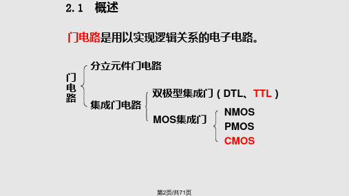
2.1 概述
二、逻辑电平 Vcc
Logic Levels
The voltages used to represent a 1 and a 0 are called logic levels.
Vo
实际开关为晶体二极管、三极
VI
管以及场效应管等电子器件
S
VI控制开关S的断、通情况。 S断开,VO为高电平;S接通,VO为低电平。
④74LS:低功耗肖特基系列;74LS系列成为功耗延迟积较小的系列。74LS系列 产品具有最佳的综合性能,是TTL集成电路的主流,是应用最广的系列。
⑤74AS:先进肖特基系列;
④74ALS:先进低功耗肖特基系列。
第24页/共71页
2.4 TTL集成门电路
74LS系列常用芯片
VCC 3A 3B 3Y 4A 4B 4Y
Implement inverter with BJT
+VCC Rc iC
Rb b
c uo
ui
iB
利用二极管的压降为0.7Ve,保证
输入电压在1V以下时,开关电路
可三靠极地管截开止关。 电路
输入为低,输出为高; A
输入为高,输出为低。
0
1
A(V) Y(V) <0.8 5 >2 0.2
YA
Y
A
1
Y
1
0
②外加反向电压,二极管截止。
门坎电压Uth 硅 PN 结伏安特性
iD(mA)
0.7V
uD(V)
第8页/共71页
2.2 半导体二极管和三极管的开关特性
二、二极管开关特性
D uI
Vcc R
uo
利用二极管的单向导电性,相当 于一个受外加电压极性控制的开关。
数字电子技术基础,英语作文500词
数字电子技术基础,英语作文500词Digital Electronics Fundamentals。
Digital electronics is a rapidly evolving field that has revolutionized the way we interact with technology. At its core, digital electronics deals with the manipulation and processing of discrete, binary signals, which are represented by two distinct states: on (1) and off (0). This binary language forms the foundation for the digital systems that power our modern world, from smartphones and computers to industrial automation and beyond.One of the fundamental building blocks of digital electronics is the logic gate. Logic gates are electronic circuits that perform basic logical operations, such as AND, OR, and NOT, on input signals to produce a desired output. These gates serve as the fundamental components of more complex digital circuits, allowing for the implementation of sophisticated algorithms and decision-making processes.Another crucial aspect of digital electronics is the concept of digital signals and their representation. Digital signals are discrete, meaning they can only take on a finite number of values, typically 0 or 1. This contrasts with analog signals, which can take on a continuous range of values. The ability to represent information using only two distinct states, combined with the speed and reliability of digital systems, has made digital electronics the preferred choice for a wide range of applications.The design and implementation of digital circuits involve various techniques and methodologies, including Boolean algebra, Karnaugh maps, and combinational and sequential logic. These tools and concepts enable engineers to create efficient and reliable digital systems that can perform complex tasks with precision and speed.One of the most significant advancements in digital electronics has been the development of microprocessors and microcontrollers. These integrated circuits, often referred to as the "brains" of digital devices, are capable of executing complex instructions and performing a wide range of computational tasks. The integration ofmicroprocessors and microcontrollers has led to the proliferation of smart devices, from smartphones and tablets to industrial automation systems and home appliances.In addition to microprocessors and microcontrollers, digital electronics also encompasses a range of other components and technologies, such as memory devices, input/output interfaces, and digital signal processing (DSP) chips. These components work together to create the sophisticated digital systems that are ubiquitous in our modern world.As digital electronics continues to evolve, we can expect to see even more remarkable advancements in the field. Emerging technologies such as quantum computing, neuromorphic engineering, and advanced materials are poised to revolutionize the way we design and implement digital systems, pushing the boundaries of what is possible.In conclusion, digital electronics is a fundamental and ever-evolving field that underpins much of the technology we rely on in our daily lives. From the logic gates that form the building blocks of digital circuits to the powerful microprocessors that drive our smart devices, digital electronics is a crucial component of the modern world. As we continue to push the limits of what is possible with digital technology, the future holds endless possibilities for innovation and progress.。
Chapter09_PPT
CommunityMemeber
Employee
Student
Alumnus
Faculty
Staff
Administrator
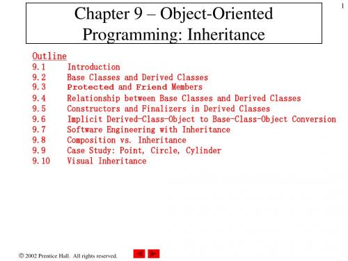
Fig. 9.2
Teacher
Inheritance hierarchy for university CCommunityMembers.
2002 Prentice Hall. All rights reserved.
Outline
CPoint.vb
6
' default constructor Public Sub New()
Declares integer variables mX and mY as Private
' implicit call to Object constructor occurs here X = 0 Y = 0 End Sub ' New ' constructor Public Sub New(ByVal xValue As Integer, _ ByVal yValue As Integer)
keyword Overrides
End Class ' CPoint
2002 Prentice Hall.
All rights reserved.
1 ' Fig. 9.5: PointTest.vb 2 ' Testing class CPoint. 3 4 Imports System.Windows.Forms 5 6 Module modPointTest Instantiates an object of class CPoint 7 8 Sub Main() Sets X and Y coordinates 9 Dim point As CPoint 10 Dim output As String 11 12 point =X New 115) ' instantiate CPoint object Changes values of andCPoint(72, Y 13 14 ' display point coordinates via X and Y properties 15 output = "X coordinate is " & point.X & _ 16 vbCrLf & "Y coordinate is " & point.Y 17 18 point.X = 10 ' set x-coordinate via X property 19 point.Y = 10 ' set y-coordinate via Y property 20 Retrieves values X and Y and 21 ' display new point value appends values to String Output 22 output &= vbCrLf & vbCrLf & _ 23 "The new location of point is " & point.ToString() 24 25 MessageBox.Show(output, "Demonstrating Class Point") 26 End Sub ' Main 27 Outputs String representation of X and Y 28 End Module ' modPointTest
数字电路英文版

8.
An Analog Electronic System
Stray capacitive [ 杂散电容 ] Duty cycle [ 占空比 ]
KEY AND KEY TERMS
Analog : Being continuous or having continuous values.
Digital : Related to digital or discrete quantities; having a set of discrete values.
systems in which there are only two
possible states. These states are
represented by two different voltage
levels: A HIGH and A LOW. 11.
The two states can also be represented by current levels, open and closed switches, or lamps turned on and off. In digital systems, combinations of the two states, called codes, are used to represent numbers, symbols, alphabetic characters, and other types of information.
数字电子技术基础,英语作文
数字电子技术基础,英语作文English: Digital electronic technology is the foundation of modern electronic devices and systems. It involves the use of digital signalsto represent and process information, enabling the creation of complex and versatile electronic devices. Understanding the basics of digital electronic technology is essential for anyone pursuing a career in electronics or related fields. This includes knowledge of binary number systems, Boolean algebra, logic gates, digital circuits, and digital signal processing. With the rapid advancement of technology, digital electronic technology continues to evolve and play a critical role in various industries such as telecommunications, computing, and consumer electronics.中文翻译: 数字电子技术是现代电子设备和系统的基础。
它涉及使用数字信号来表示和处理信息,从而实现复杂多样的电子设备的创建。
了解数字电子技术的基础知识对于任何追求电子学或相关领域职业的人来说至关重要。
数字电子技术大纲 英文

Teaching Programme Of Digital Electronic Technology 一、Basic information of courseCourse title: Digital electronic technologyEnglish name: Digital electronic technologyCourse nature: compulsory courseCourse number: 02Weekly hours: three hoursTotal hours: 48 hoursLearning points: three pointsApplicable to professional : Applicable to each major of the information engineering collegeprerequisite knowledge: circuit\analog electronics techniqueteaching material: Thomas L.Floyd, Digital Fundamentals,(Tenth edition), publishing house of electronics industry, Oct 2011Appraisal method: examination二、Aim and task of courseDigital electronic technology is one of the core courses designed for sophomores in all curricular relating to electrical engineering and computer science. The overall goals are to analyze and design digital logic circuits which constitute the foundation for preparing a student to take follow-on courses, develop skills required to solve engineering problems. Main topics include digital systems and codes, logic gates, Boolean algebra, logic simplification, combinational logic circuits, flip-flops and related devices, programmable logic devices, sequential logic circuits, large-scale integrated circuits, and analog-to-digital and digital-to-analog converters.三、Course content and course scheduleChapter 1 Logic Algebra (7 hours)一、The basic requirements of this chapter1. Master the conversion among binary, decimal and hexadecimal;2.Master symbol、truth table and function expression of the three basic logic operations, the basic formula of logic algebra3.. Master logic function simplification using formula method and karnaugh map二、Teaching contents1. Introduction2. logic algebra3. logic functionChapter 2 gate circuit (six hours)一、The basic requirements of this chapter1.Understand the working features of the triode in the state of switch, the workingprinciple of TTL inverter,Master static input and output characteristics of the TTL inverter2. Understand the working principle of CMOS inverter二、Teaching contents1. TTL gate circuit2. CMOS gate circuitChapter 3 combinational logic circuit(8 hours)一、The basic requirements of this chapter1. Understand the features of combinational circuits, Master the analysis method of combinational circuits2. Master the analysis method of combinational circuits3.Master the working principle and the using method of the commonly used combinational logic devices including : encoder, decoder, and data selector , Understand r and the working principle of adders and numerical comparator.二、Teaching contents1. Analysis of Combinational Logic Circuit2.Design of Combinational Logic Circuit3. Several commonly used combinational logic circuitChapter 4 Flip-flops(5 hours)一、The basic requirements of this chapter1.Understand the characteristics and classification of flip-flops;2.Understand circuit structure and action characteristic of basic RS flip-flops and synchronous RS flip-flops; Master circuit structure and action characteristic ofMaster-Slave JK and D flip-flops;3.Understand property list、the characteristic equation and state transition diagram that describe the logic functions of flip-flops.二、Teaching contents1.Introduction2.circuit structure and action characteristic of flip-flops3.Logic function and description method of flip-flopsChapter 5 Sequential logic circuit(8 hours)一、The basic requirements of this chapter1.Understanding the characteristics and structure of the sequential logic circuit; 2.Master the analysis method of the synchronous sequential logic circuit, acquire these skills of writing drive equation and state equation and output equation of the circuit, drawing state transition diagram;3.Understand the working principle of shift register registers and counters, grasp common counter chips and counter connection method4.Understand the design method of synchronous sequential logic circuit.二、Teaching contents1.Introduction2.Analysis method of the sequential logic circuit3.Some common sequential logic circuit4.Design method of synchronous sequential logic circuitChapter 6 Pulse waveform generation and shaping (5 hours)一、The basic requirements of this chapter1. Understand several main parameters describing pulse waveform;2. Understand the role and action characteristics of Schmitt trigger composed by gate circuit,understand the definition and determination method of characteristic parameters VT +、VT— and ΔVT, know the application of Schmitt trigger3.Understand the role and operation characteristics of one-shot that is composed of gate circuit ;;4.Understand the working principle of symmetric multivibrator and multivibrator composed by Schmitt trigger;5.Master the circuit structure and function of 555 timer, Calculate the parameters of Schmitt trigger and multivibrator composed by 555 timer.二、Teaching contents1.Introduction2.Schmitt trigger3.one-shot that is composed of gate circuit4.multivibrator5.555 timer and its applicationChapter 7 large scale integrated circuit (3 hours)一、The basic requirements of this chapter1.Know classification of semiconductor memory, Know working principleof the masked ROM, know the characteristics of the programmable read-only memory, know the characteristics of the programmable read-only memory and erasable programmable read only memory;2.Understand the structure and working principle of the static random access memory; 3.To grasp the way of storage capacity and memory is used to implement the concept of combined logic function. Master memory capacity expansion mode and the concept of realization of combinational logic with memory .二、Teaching contents1.Introduction2.Read-only memory (ROM)3.Random access memory4.The extension of storage capacityChapter 8 programmable logic device (2 hours)一、The basic requirements of this chapterUnderstand the logic graphic symbol of the programmable logic devices, Understand the circuit structure and working principle of PAL二、Teaching contents1.Programmable Logic Array(PAL)2.Generic array logic(GAL)Chapter 9 digital-analog and analog-to-digital conversion (4 hours) 一、The basic requirements of this chapter1.master the basic concept of D/A converter, Understand the basic working principle of D/A converter、the conversion accuracy and conversion speed of D / A converter,Understand the calculation of input and output relationship of D/A converter;2.master the basic concept of A/D converter, Understand the basic working principle of A/D converter、the conversion accuracy and conversion speed of A/D converter,know the main types, structure features, basic working principle and performance comparison of A/D converter.二、Teaching contents1.D/A converter2.A/D converter。
数字电子技术英文版

Nothing Special about 10!
Decimal system (and the idea of “0”) was invented in India around 100-500AD.
Why did they use 10? Anything special about it?
• What about base 2?
2-2 BINARY NUMBERS 二进制数
Introductory Paragraph
The binary number system is simply another way to represent quantities. The binary system is less complicated than the decimal system because it has only two digits. It may seem more difficult at first because it is unfamiliar to you. The decimal system with its ten digits is a base-ten system; the binary system with its two digits is a base-two system. The two digits (bits) are 1 and 0. The position of a 1 or 0 in a binary number indicates its weight, or value within the number, just as the position of a decimal digit determines the value of that digit. The weights in a binary number are based on powers of two.
数字电子技术基础英文版课件
Logic Levels
Binary values are also represented by voltage levels
They can also be called LOW and HIGH, where LOW = 0 and HIGH = 1 In positive logic rules:
Slide 14
1-2 Binary Digits, Logic Levels, and Digital Waveforms 二进制数,逻辑电平和数字波形
Slide 15
Binary Digits
• The conventional numbering system uses ten digits: 0,1,2,3,4,5,6,7,8, and 9. • The binary numbering system uses just two digits: 0 and 1. • Each of the two digits is called bit, which is a contraction of the words binary digit. • Groups of bits (combinations of 1s and 0s)is called code.
1 f T
Slide 21
An important characteristic of a digital waveform is its duty cycle. The duty cycle(占空比) of a binary waveform is defined as:
tw Duty cycle 100% T
Slide 17
Slide 18
数字电子技术(英文版,chapter01)

Other reference books
Recommended:清华大学电子学教研组 编,阎石主编,数字电子技术基础,第四版, 高等教育出版社,7-04-006696-3
Recommended:王毓银主编,数字电路逻 辑设计〔脉冲与数字电路,第三版〕,高等 教育出版社,7-04-007730-2
Recommended:Digital Logic Applications and Design by John M. Yarbrough, China Machine Press & Thomson Learning, 7-111-10837-X
Digital Fundamentals 7/E
design digital logic circuits
Topics
digital systems and codes, logic gates, Boolean algebra, logic simplification, combinational logic circuits, flip-flops and related devices, programmable logic devices, sequential logic circuits, large-scale integrated circuits analog-to-digital and digital-to-analog
The two-state number system is called binary, and its two digits are 0 and 1.
A binary digit is called a bit.
Binary Digits
The two digits in the binary system, 1 and 0, are called bits, which is a contraction of the words binary digit.
数字电子技术(课件)lec09
Chapter 5 Combinational Logic Analysis
8
Lecture 9: Combinational Logic Analysis--2
Development of the AND-OR Equivalency
注意:变换符号时从输 出往输入逆向操作。
2013-7-28
Test Your Understanding
Draw the timing diagram for the circuit below, showing the output of G1,G2 and G3 with the input waveforms A and B.
2013-7-28
Chapter 5 Combinational Logic Analysis
10
Lecture 9: Combinational Logic Analysis--2
Test Your Understanding
Directly simplify the logic diagram shown below using the appropriate dual symbols and develop the output expression for the circuit.
Chapter 5 Combinational Logic Analysis
9
Lecture 9: Combinational Logic Analysis--2
Illustration of the Use of Appropriate Dual Symbols
error
Start from output, and work backwards
数字电子技术大纲英文
Teaching Programme Of Digital Electronic Technology一、of courseCourse title: Digital electro nic tech no logyEn glish n ame: Digital electro nic tech no logyCourse nature: compulsory courseCourse nu mber: 02Weekly hours: three hoursTotal hours: 48 hoursLear ning poin ts: three pointsApplicable to professional: Applicable to each major of the information engineering college prerequisite kno wledge: circuit\a nalog electr onics tech niqueteachi ng material: Thomas , Digital Fun dame ntals,(Te ntheditio n), publish ing house of electro nics in dustry, Oct 2011 Appraisal method: exam in ati on二、Aim and task of courseDigital electro nic tech no logy is one of the core coursesdesig ned for sophomores in all curricular relati ng to electrical engin eeri ng and computer scie nee. The overall goals are to analyze and design digital logic circuits which constitute the foundation for preparing a stude nt to take follow-on courses, develop skills required to solve engin eeri ng problems. Main topics include digital systems and codes, logic gates, Boolean algebra, logic simplificati on, comb in ati on al logic circuits, flip-flops and related devices, programmable logic devices, sequential logic circuits, large-scale integrated circuits, and analog-to-digital and digital-to-analog converters.三、Course content and course scheduleChapter 1 Logic Algebra (7 hours )一、The basic requirements of this chapter1. Master the conv ersi on among bin ary, decimal and hexadecimal2. Master symbol、truth table and fun cti on expressi on of the three basic logic operations, the basic formula of logic algebra3. . Master logic function simplification using formula method and karnaugh map二、Teachi ng contents1. In troducti on2. logic algebra3. logic fun ctio nChapter 2 gate circuit (six hours)一、The basic requirements of this chapter1. Understand the working features of the triode in the state of switch, the workingprinciple of TTL inverter,Master static in put and output characteristics of the TTL inv erter2. Understand the working principle of CMOS inverter二、Teachi ng contents1. TTL gate circuit2. CMOS gate circuitChapter 3 comb in ati on al logic circuit (8 hours)一、The basic requirements of this chapter1. Un dersta nd the features of comb in ati onal circuits, Master the an alysis method of comb in ati onal circuits2. Master the an alysis method of comb in ati onal circuits3. Master the working principle and the using method of the commonly used comb in ati on al logic devices in clud ing : en coder, decoder, and data selector , Un dersta nd r and the work ing prin ciple of adders and nu merical comparator.二、Teachi ng contents1. An alysis of Comb in ati onal Logic Circuit2. Desig n of Comb in ati onal Logic Circuit3. Several com monly used comb in ati on al logic circuitChapter 4 Flip-flops (5 hours)一、The basic requirements of this chapter1. Understand the characteristics and classification of flip-flops;2. Understand circuit structure and action characteristic of basic RS flip-flops and synchronous RS flip-flops; Master circuit structure and acti on characteristic of Master-Slave JK and D flip-flops;3. Understand property list、the characteristic equation and state transition diagram that describe the logic functions of flip-flops.二、Teachi ng contents1. Introduction2. circuit structure and action characteristic of flip-flops3. Logic function and description method of flip-flopsChapter 5 Seque ntial logic circuit (8 hours)一、The basic requirements of this chapter1. Understanding the characteristics and structure of the sequential logic circuit;2. Master the analysis method of the synchronous sequential logic circuit, acquire these skills of writing drive equation and state equation and output equation of the circuit, draw ing state tran siti on diagram;3. Understand the working principle of shift register registers and counters, grasp com mon coun ter chips and coun ter connection method4. Understand the design method of synchronous sequential logic circuit.二、Teachi ng contents1. Introduction2. Analysis method of the sequential logic circuit3. Some com mon seque ntial logic circuit4. Design method of synchronous sequential logic circuitChapter 6 Pulse waveform gen erati on and shap ing (5 hours)一、The basic requirements of this chapter1. Un dersta nd several main parameters describ ing pulse waveform;2. Understand the role and action characteristics of Schmitt trigger composed by gatecircuit,u ndersta nd the defi niti on and determ in ati on method of characteristic parameters VT +、VT —and △ VT, know the application of Schmitt triggerthe role and operati on characteristics of on e-shot that is composed of gate circuit;the worki ng prin ciple of symmetric multivibrator and multivibrator composed by Schmitt trigger;5. Master the circuit structure and function of 555 timer, Calculate the parameters of Schmitt trigger and multivibrator composed by 555 timer.二、Teachi ng contents1. Introduction2. Schmitt trigger3. one-shot that is composed of gate circuit4. multivibrator5. 555 timer and its application\ Chapter 7 large scale in tegrated circuit (3 hours)一、The basic requirements of this chapter1. Know classificatio n of semic on ductor memory, Know worki ng prin cipleof the masked ROM, know the characteristics of the programmable read-only memory, know the characteristics of the programmable read-only memory and erasable programmable read on ly memory;2. Understand the structure and working principle of the static random access memory;3. To grasp the way of storage capacity and memory is used to implement the concept of comb ined logic fun cti on. Master memory capacity expa nsion mode and the con cept of realizati on of comb in ati on al logic with memory .二、Teachi ng contents1. Introduction2. Read-only memory (ROM)3. Random access memory4. The extension of storage capacityChapter 8 programmable logic device (2 hours)一、The basic requirements of this chapterUnderstand the logic graphic symbol of the programmable logic devices, Understand the circuit structure and work ing prin ciple of PAL二、Teachi ng contents1. Programmable Logic Array (PAL)2. Gen eric array logic( GAL)Chapter 9 digital-a nalog and an alog-to-digital conversion (4 hours)一、The basic requirements of this chapter1. master the basic concept of D/A converter, Understand the basic working principle of D/A converter、the conversion accuracy and conversion speed of D / A converterUn dersta nd the calculatio n of in put and output relati on ship of D/A conv erte;2. master the basic concept of A/D converter, Understand the basic working principle of A/D converter、the conversion accuracy and conversion speed of A/D converterknow the main types, structure features, basic work ing prin ciple and performa nee comparis on of A/D conv erter.二、Teachi ng contents1. D/A converter2. A/D converter。
数字电子技术基础,英语作文

数字电子技术基础,英语作文The Fundamentals of Digital Electronic Technology.Digital electronic technology is the backbone of modern electronics, serving as the foundation for a wide range of devices and systems that shape our world. From smartphones and computers to complex industrial control systems and space exploration equipment, digital electronics plays a crucial role in enabling these advancements.At its core, digital electronics deals with the representation and manipulation of information using discrete values, typically binary numbers. These binary values, consisting of only two states – 0 and 1 – form the building blocks of all digital systems. This simplicity in representation allows for highly efficient and reliable data processing, making digital electronics the preferred choice for many modern applications.The fundamental components of digital electronics arelogic gates. These are basic building blocks that perform logical operations on binary inputs to produce a binary output. The most common logic gates include the AND gate, OR gate, NOT gate, and others. By combining these logic gates in different configurations, complex digital circuits can be created to perform a wide range of tasks.Digital circuits are designed using principles such as Boolean algebra, which provides a mathematical frameworkfor analyzing and designing logic circuits. This allows engineers to predict the behavior of digital systems and optimize their design for specific applications.Beyond logic gates, digital electronics also encompasses a range of other technologies and concepts. Microprocessors, for instance, are digital devices that execute instructions stored in memory to perform complex tasks. Memory devices like RAM and ROM store and retrieve data in digital format, enabling computers and other systems to retain information.Digital signal processing is another crucial aspect ofdigital electronics. It involves the manipulation and analysis of digital signals to extract useful information or modify their characteristics. This is essential in areas like audio processing, image processing, and communications systems.The rapid development of digital electronics has been enabled by advancements in semiconductor technology. The miniaturization of transistors and other electronic components has led to the creation of integrated circuits (ICs), which pack millions or even billions of transistors onto a single chip. This has made digital electronics more efficient, reliable, and cost-effective, driving the revolution in consumer electronics and beyond.In conclusion, digital electronic technology is the backbone of modern electronics, enabling the creation of complex and sophisticated systems that have transformed our world. Its fundamental principles, such as binary representation, logic gates, and Boolean algebra, provide a solid foundation for understanding and developing digital systems. As technology continues to evolve, digitalelectronics will play an even more critical role in shaping the future of electronics and beyond.。
chapter09

1. The polymerase chain reaction in outline 2. PCR in more detail 3. Applications of PCR
9.1 PCR in outline PCR reaction: ● Template ● Primers ● DNA polymerase
1. Denature
(变性)
2. Annealing
(退火)Байду номын сангаас
3. Extension
(延伸)
4. Cycling
PCR
9.2 PCR in more detail 1. Designing the oligonucleotide primers for a PCR
Primers: 根据位置分: 5’-end primer 3’-end primer Forward primer Reverse primer Sense primer Antisense primer Upstream primer Downstream primer
根据序列性质分: Specific primer (专一) Degenerated primer(兼并)
Random primer(随机)
The result of PCRs with well-designed and poorly-designed primers
Lane 1: good
Lane 2: nothing
(2) Cloning PCR products
● Using the property of Taq polymerase
T cloning vector vector Blunt end vector dTTP polymerase T tailed vector
Chapter-09

Criminal Enterprise Behavior
1. 2.
3.
4. 5. 6.
act quickly and precisely to make their activities harder to detect exploit perimeter via vulnerable ports use trojan horses (hidden software) to leave back doors for re-entry use sniffers to capture passwords do not stick around until noticed make few or no mistakes.
benign intruders might be tolerable
IDS / IPS / VPNs can help counter awareness led to establishment of CERTs
collect / disseminate vulnerability info / responses
benign: explore, still costs resources serious: access/modify data, disrupt system
range
led
to the development of CERTs intruder techniques & behavior patterns constantly shifting, have common features
Criminal Enterprise
organized
数字电子技术Lecture09
An Asynchronous Decade Counter
A Synchronous Decade Counter
J0 K0 1 J1 K1 Q0 Q3 J2 K2 Q0Q1 J3 K3 Q0Q1Q2 Q0Q3
74HC163: 4-Bit Synchronous Binary Counter
LOAD = Parallel load EP, ET = Enable count RCO = Ripple clock output TC = Terminal count = 1111
• Counters can also be designed to have a number of states in their sequence that is less than 2n. The resulting sequence is called a truncated sequence.
• One common modulus for counters with truncated sequences is ten (called MOD 10). Counters with ten states in their sequence are called decade counters. A decade counter with a count sequence of 0 through 9 is a BCD decade counter.
- 1、下载文档前请自行甄别文档内容的完整性,平台不提供额外的编辑、内容补充、找答案等附加服务。
- 2、"仅部分预览"的文档,不可在线预览部分如存在完整性等问题,可反馈申请退款(可完整预览的文档不适用该条件!)。
- 3、如文档侵犯您的权益,请联系客服反馈,我们会尽快为您处理(人工客服工作时间:9:00-18:30)。
No –change condition
Toggle condition
A 3-Bit Synchronous Binary Counter
J0 K0 1 J1 K1 Q0 J 2 K 2 Q0Q1
•FF0 is held in the toggle mode by constant HIGHs on its data inputs.
Timing Example for a 74HC163
74HC160: Synchronous BCD Decade Counter
LOAD = Parallel load EP, ET = Enable count RCO = Ripple clock output
A 3-Bit Asynchronous Binary Counter
A 3-bit counter goes through a binary sequence (000, 001, 010, 011, 100, 101, 110, 111).
A 3-Bit Asynchronous Binary Counter
1-digit octal counter counter
A 4-Bit Asynchronous Binary Counter
An Asynchronous Decade Counter
The modulus of a counter is the number of unique states that the counter will sequence through. The maximum possible number of states (maximum modulus) of a counter is 2n, where n is the number of flipflops in the counter. Counters can also be designed to have a number of states in their sequence that is less than 2n. The resulting sequence is called a truncated sequence. One common modulus for counters with truncated sequences is ten (called MOD 10). Counters with ten states in their sequence are called decade counters. A decade counter with a count sequence of 0 through 9 is a BCD decade counter. To obtain a truncated sequence, it is necessary to force the counter to recycle before going through all of its possible states.
• When Both Q0 and Q1 are HIGH, FF2 is in the toggle mode.
•When Q0, Q1 and Q2 are all HIGH, FF3 is in the toggle mode.
A 4-Bit Synchronous Binary Counter
CLK Q0
Q0 ( LSB) 0
Q1 ( MSB)
1
0
0
0
1
1 1
0 0
A 2-Bit Asynchronous Binary Counter
This circuit is a 2-bit counter because it exhibits four different states (00, 01, 10, 11). In other words, it goes through a binary sequence (00, 01, 10, 11). It actually counts the number of clock pulses up to three, and on the fourth pulse it recycles to its original state.
A 4-Bit Synchronous Binary Counter
J0 K0 1 J 1 K1 Q0 J 2 K 2 Q0Q1 J 3 K 3 Q0Q1Q2
•FF0 is held in the toggle mode by constant HIGHs on its data inputs. • When Q0 is a 1 FF1 is in the toggle mode.
•FF0 is held in the toggle mode by constant HIGHs on its data inputs.
• When Q0 is a 1 FF1 is in the toggle mode. • When Both Q0 and Q1 are HIGH, FF2 is in the toggle mode.
An Asynchronous Decade Counter
glitch: a false or spurious electronic signal.
An Asynchronous Modulus-12 Counter •This example shows how an asynchronous counter can be implemented having a modulus of 12 with a straight binary sequence from 0000 through 1011.
74HC163: 4-Bit Synchronous Binary Counter
LOAD = Parallel load EP, ET = Enable count RCO = Ripple clock output
TC = Terminal count = 1111
Function Table for 74HC163
• When Q0 is a 1 FF1 is in the toggle mode. • When Both Q0 and Q1 are HIGH, FF2 is in the toggle mode.
A 3-Bit Synchronous Binary Counter
J0 K0 1 J1 K1 Q0 J 2 K 2 Q0Q1
•But this circuit is not very reliable.
•So, it is improved by adding additional logic.
74LS93A: 4-Bit Asynchronous Binary Counter
•It can be used as a divide-by-2 device if only the single FF is used. •It can be used as a modulus-8 counter if only the 3-bit counter portion is used.
A Synchronous Decade Counter
J 0 K0 1 J1 K1 Q0 Q 3 J 2 K 2 Q0Q1 J 3 K3 Q0Q1Q2 Q0Q3
A Synchronous Decade Counter
J 0 K0 1 J1 K1 Q0 Q 3 J 2 K 2 Q0Q1 J 3 K 3 Q0Q1Q2 Q0Q3
9-2SYNCHRONOUS COUNTER OPERATION •Synchronous means that all the FFs in the counter are clocked at the same time by a common clock pulse. •FF0 is always connected for toggle operation. •When the leading edge of CLK occurs, FF1 toggles if Q0 is 1, otherwise it remains in its present state. •There is a propagation delay from the triggering edge of the clock pulse until the Q output actually makes a transition.
CHAPTER 9
Counters
第8章 Problems: 2,4,8,12,17,20,21,29, 34
Synchronous and Asynchronous Counters 同步和异步计数器
Flip-flops can be connected together to perform counting operations. Such a group of flip-flops is a counter. Counters are classified into two broad categories according to the way they are clocked: asynchronous and synchronous. The term asynchronous refers to events that do not have a fixed time relationship with each other and, generally, do not occur at the same time. In asynchronous counters, commonly called ripple counters, the first flip-flop is clocked by the external clock pulse and then each successive flip-flop is clocked by the output of the preceding flipflop. So the flip-flops within an asynchronous counters do not change states at exactly the same time In synchronous counters, the clock input is connected to all of the flip-flops so that they are clocked simultaneously.
