3W5W四脚直插18mm全彩灯珠 RGB射灯光源共阳规格书
F5MM全彩键盘灯规格书

1 波峰焊 2 温度循环 3 冷热冲击 4 高温储存 5 低温储存 6 常温点亮老化 7 高温高湿
TEMP : 260℃ ± 5℃
H : +100℃ 15min ∫ 5 min
L : -40℃ 15min H : +100℃ 5min
∫ 10 sec L : -10℃ 5min
TEMP : 100℃
Rev.: A
Prepared by: calvin chai
Page: 5 of 6
Technical Data Sheet 直插 LEDs
■ 使用说明
1. LED 储存条件:温度 10℃-26℃,湿度%40-%65,包装袋密封保存。
2.接触 LED 检查时需戴手套或手指套,工作台面也要接地,包装袋开口后及时封口,防止脚位氧化。 3.插件,这一过程主要是静电的防护:
Technical Data Sheet 直插 LEDs
客户名称 Client appellation: 产品型号 Model NO.: 产品规格 Specification: 样品编号 NO.:
承认书
全彩共阳 RGB(异形) 直插 LEDs
Approved by
Engineer
Client affirm
注明: *1:焊锡时间 ≦ 5 秒.
符号
IF
IFP Pd Topr Tstg Tsol VR
值
75
100 150 -40 to +85 -40 to +90 250±5 5
单位
mA mA mW ℃ ℃ ℃ V
Device No. : LDS-LAMP -001 Prepared date: 2017-09-21
3535RGB规格书
承认书客户名称Client appellation:产品型号Model NO.: 3535RGB(晶元全彩)产品规格Specification: 3535 Top View LEDs样品编号NO.:、■特征:●宽角度全彩LED●支架有6个PIN脚●具有宽的发光角度●上锡方式:回流焊●抗静电●无铅●符合ROHS■描述 :●3535产品拥有宽的发光角度及高光效,该全彩产品采用蓝色、红色、绿色波长芯片加特殊工艺制作而成■用途:●背光●灯条●模组■外观描述:■封装尺寸1. 所有标注尺寸的单位均为毫米2. 除了特别注明,所有标注尺寸的公差均为±0.10mm█绝对最大额定值(Ta = 25℃)参数符号值单位正向电流IF 90 mA 峰值正向电流(Duty 1/10 @1KHz) IFP 100mA 功耗Pd 330 mW 操作温度Topr -40 to +85 ℃保存温度Tstg -40 to +90 ℃静电防护ESD 2000 V 回流焊最高温度Tsol 260±5 ℃反向电压VR 5 V 注明: *1:回流焊时间≦ 5 秒.█电性与光学特性(Ta=25℃)█信赖性测试项目与条件: 产品的可靠性应满足于下列项目:信任级别:90%Notes:Ivt: 信赖性测试前Iv值;Iv: 完成信赖性测试后Iv值;U:规格上限值L:规格下限值■使用说明1. 过电流保护客户必须使用电阻来保护,否则电压的漂移会引起电流的大幅度改变(发生击穿现象).灯珠使用时电流必须在规定范围之内,避免电流过大造成不良。
2. 储存2-1. 准备使用产品前不要打开防潮袋。
开封前请先检查包装袋有无漏气,开包后检查湿度标示卡20%RH 标示区有无由蓝色变为粉红色.如漏气或变色现象,请联系厂家或退回厂家高温除湿处理,(高温除湿环境:120度,6H)切勿自行处理2-2. 打开包装前,LEDs需储存在温度低于30℃,湿度低于70%RH 。
led射灯说明书

led射灯说明书
LED射灯说明书
一、产品概述
LED射灯是一种高效、节能、环保的照明设备,采用高品质的LED灯珠作为发光源,具有亮度高、色温可选、寿命长等优点。
适用于家庭照明、商业照明、景观照明等多种场景。
二、产品规格
1. 输入电压:AC90-240V
2. 光源:LED灯珠
3. 灯体功率:18W
4. 色温:3000K/4200K/6400K可选
5. 输出光通量:1350Lm
6. 环境温度:-20℃-40℃
7. 灯体效率:75Lm/W
8. 寿命:>30000小时
9. 发光角度:28°/38°可选
10. 外观颜色:银色/金色
三、使用方法
1. 将LED射灯安装在指定位置,确保灯体稳固,避免晃动或掉落。
2. 根据需要选择合适的色温,通过调节开关或遥控器进行控制。
3. 使用过程中请避免长时间打开或关闭,以免影响寿命。
4. 请定期清洁灯罩表面,保持干净整洁。
四、注意事项
1. 请勿在潮湿环境下使用LED射灯,以免造成短路或损坏。
2. 请勿随意拆卸或改装LED射灯,以免造成安全隐患。
3. 请勿在高温环境下使用LED射灯,以免影响寿命或造成损坏。
4. 请勿将LED射灯长时间直射人眼,以免造成视力损伤。
C3W全彩版产品介绍

C3W全彩版产品介绍E Z V I Z20191简介通过本篇课程,可以学习到:1.C3W 全彩版特色功能①全彩夜视②DIY 个性化语音提示③H.265技术④15米远程拾音⑤声光主动防御功能⑥双向语音对讲⑦双天线Wi-Fi ⑧IP66防水防尘⑨AP 热点功能2.产品安装及初次使用方法3.常见操作①AP 热点功能②夜视模式选择③自定义语音提示④画面翻转⑤全天录像设置4.常见问题:①AP 热点功能②夜视模式③自定义语音提示④声光报警EZ V I Z2019 10目录基本介绍01 产品型号02 产品外观03 特色功能C O N T E N T S常见操作01 设备端02 APP 客户端03 PC 客户端初次使用01 装箱清单02 产品安装03 初次使用FAQ01 产品参数02 功能使用03疑难问题EZ V I Z2019 100 1一、基本介绍产品型号产品外观特色功能EZ V I Z2019 10产品型号与外观CS-C3W-1H2WKFLEZ V I Z2019 10产品外观⏹正文1⏹正文2正文标题E Z V I Z20191外观介绍⏹正文1⏹正文2正文标题*指示灯红色常亮:启动中红色慢闪:网络断开蓝色慢闪:正常工作红色快闪:故障蓝色快闪:AP 配网模式EZ V I Z2019 10特色功能E Z V I Z20191四灯全彩夜视,夜间也多彩全彩夜视效果普通夜视效果四灯夜视(两颗大功率暖光灯+两颗红外灯),配合四颗专业级光学透镜,应用在室外、门口、商超、工厂等场景,实现夜间全彩监控效果,从此告别夜间黑白的单调监控模式EZ V I Z2019 101080P高清画质大光圈镜头,搭配sony星光级传感器,带来更清晰的1080P图像体验。
色彩更丰富,画质更细腻E Z V I Z20191两种夜视模式,随心按需切换⏹正文1⏹正文2正文标题全彩模式暖光灯开启,可同时起到照明效果黑白模式暖光灯关闭,免强光干扰E Z V I Z20191暖光灯亮度随心调节⏹正文1⏹正文2正文标题应用场景:用在庭院、沿街商铺、等场景,可以开启暖光灯,并且支持按需调节亮度E Z VI Z20191副标题1⏹正文1⏹正文2正文标题采用新一代视频编码技术,同等带宽下,传输更高质量的视频;同清晰度下,占用的存储空间及带宽减少50%。
3wled灯珠参数

3wled灯珠参数介绍3wled灯珠是一种高亮度、高效能的LED照明产品。
本文将详细探讨3wled灯珠的参数,包括功率、光通量、光效、发光角度、色温和色彩指数等。
通过深入了解这些参数,我们可以更好地选择和使用3wled灯珠。
功率3wled灯珠的功率是指LED芯片的电力消耗。
一般情况下,功率越高,LED的亮度和光通量也就越大。
3wled灯珠的功率一般为3瓦,这意味着它的能耗比传统的白炽灯和荧光灯低得多,是一种非常节能的照明产品。
光通量光通量是指3wled灯珠的发光功率。
它用单位时间内从光球中发出的光的总功率来衡量。
3wled灯珠的光通量一般在200-300流明之间,与传统的白炽灯相比,其光通量相当于约30瓦的白炽灯。
光效光效是指3wled灯珠的亮度与功率的比值,即单位功率下产生的亮度。
光效一般以流明/瓦(lm/W)来衡量,数值越大,表示能量的利用率越高。
3wled灯珠的光效一般在80-100lm/W之间,是一种非常高效能的照明产品。
发光角度发光角度指的是3wled灯珠的光束扩散范围。
发光角度的大小会影响照明的范围和光照强度。
较大的发光角度适合用于大范围的照明,而较小的发光角度适合用于局部照明。
一般来说,3wled灯珠的发光角度为120度左右。
色温色温是指光线的颜色。
色温以开尔文(K)为单位来表示,数值越高,表示光线的颜色偏白,数值越低,表示光线的颜色偏黄。
3wled灯珠的色温一般有2700K(暖白光)、4000K(自然白光)和6000K(冷白光)等选择。
不同的场景和需求可以选择不同色温的3wled灯珠。
色彩指数色彩指数是指3wled灯珠能准确还原物体真实颜色的能力。
色彩指数一般以Ra来衡量,数值越大,表示色彩还原能力越好。
一般来说,3wled灯珠的色彩指数达到80以上,可以准确还原物体的颜色。
总结本文详细探讨了3wled灯珠的参数,包括功率、光通量、光效、发光角度、色温和色彩指数等。
通过了解这些参数,我们可以更好地理解和选择3wled灯珠。
LG3535 (3W) 灯珠详细参数
4 / 31
5. Electro - Optical Characteristics
CCT If (mA) 350 6500K (F) 700 1000 1500 350 5700K (G) 700 1000 1500 350 5000K (H) 700 1000 1500 350 4000K (J) 700 1000 1500 350 3500K (K) 700 1000 1500 350 3000K (L) 700 1000 1500 350 2700K (M) 700 1000 1500 Vf (V) 2.98 3.17 3.31 3.50 2.98 3.17 3.31 3.50 2.98 3.17 3.31 3.50 2.98 3.17 3.31 3.50 2.98 3.17 3.31 3.50 2.98 3.17 3.31 3.50 2.98 3.17 3.31 3.50 Power (W) 1.043 2.219 3.310 5.250 1.043 2.219 3.310 5.250 1.043 2.219 3.310 5.250 1.043 2.219 3.310 5.250 1.043 2.219 3.310 5.250 1.043 2.219 3.310 5.250 1.043 2.219 3.310 5.250 Φv (Im) 135 240 314 417 135 240 314 417 135 240 314 417 119 208 269 353 112 197 255 338 108 188 244 325 103 180 234 311 lm/W 129 108 95 79 129 108 95 79 129 108 95 79 114 94 81 67 107 89 77 64 104 85 74 62 99 81 71 59
照明灯具产品参数手册
LXPT MC20 HE WT 830 L90 LXPT MC20 HE WT 840 L90 LXPT MC20 HE WT 765 L90 LXPT MC20 ECO WT 830 L90 LXPT MC20 ECO WT 840 L90 LXPT MC20 ECO WT 765 L90 LXPT MC12 ECO WT 830 L90 LXPT MC12 ECO WT 840 L90 LXPT MC12 ECO WT 765 L90
10.2 GLAXIER凌星T5吸顶灯 C104 鸟巢型
10.2 GLAXIER凌星T5吸顶灯 C10 G2畅明LED路灯
11.2 绚亮LED路灯
11.1
目录 | 室外
泛光灯
12.1
12.1 PURSOS LED FLOOD 绚丽LED泛光灯
12.2 PURSOS® High Power LED Flood Light
绚丽LED筒灯 8'
绚丽LED筒灯 6'
绚丽LED筒灯 4'
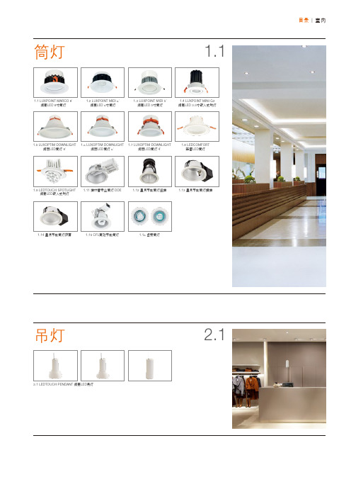
1.8 LEDCOMFORT 皓睿LED筒灯
1.9 LEDTOUCH SPOTLIGHT 绚亮LED嵌入式射灯
1.11 插拔管专业筒灯 DDE
1.12 星月节能筒灯竖插
1.13 星月节能筒灯横插
1.14 星月节能筒灯防雾
1.15 CFL高效节能筒灯
极坐标光强分布 LXPT MC20 ECO 4000K
极坐标光强分布 LXPT MC20 ECO 6500K
1.1
筒灯 | 绚亮LED筒灯 极坐标光强分布 LXPT MC12 ECO 3000K
极坐标光强分布 LXPT MC12 ECO 4000K
极坐标光强分布 LXPT MC12 ECO 6500K
Citiled COB系列LED灯光产品说明书
DATA SHEETIntroduction Performance Characteristics Mechanical Dimensions Characteristic Curves ReliabilityPacking Specification PrecautionP 2P 3P 5P 6P 9P 10P 11 CITILED COB SeriesStandard Type.Ra80 Min. ModelCLU03J-1206C91. Introduction1-1. Product Description1-2. Features・Mechanical Dimensions :19 × 19 × 1.4 (mm)・Package Structure :Aluminum Base Chip on Board ・Reference Assembly :M3 screw, Connector ・CRI (Ra):80 Min.・Nominal CCT :2,700K, 3,000K, 3,500K, 4,000K, 5,000K ,6,500K ・Chromaticity Range :2-step Ellipse, the center refers to ANSI C78.377:2017.・Thermal Resistance :0.61C/W ・Maximum drive current :1080mA ・UL recognized component (E358566)・RoHS compliant・Better die arrangement for optics・Wide range of luminous flux and high efficacy・Improved lumen density compared with previous version CLU03J -1206C9-272M2U1[1][2][3][4][5][1]:[2]:[3]:[4]:[5]:Nominal CCT CRI (Ra)Product NomenclatureCLU03J 12062700K 80 Min.Product shape Die count in series Die count in parallel CITIZEN ELECTRONICS is the first COB manufacturer. Our advanced knowledge and packaging technology for many years have excellent reliability and high quality. By optimizing each production process, the chromaticity range has achieved 2-step ellipse as a standard specification. 2-step ellipse color definition at Tj=85C ensures uniform optical performance in various applications.The new model shares the same outline design and LES size as Standard Type (Ver.1~6).( Tj=85C )Ra R9Tc25C*Min.Min.Min.Typ.Typ.Typ.Min.Typ.Max.CLU03J-1206C9-272M2U12700K 8002,3642,6872,97214954030.633.336.00.61CLU03J-1206C9-302M2U13000K 8002,4632,8003,09615654030.633.336.00.61CLU03J-1206C9-352M2U13500K 8002,5072,8493,151********.633.336.00.61CLU03J-1206C9-402M2U14000K 8002,5272,8723,177********.633.336.00.61CLU03J-1206C9-502M2U15000K 8002,5572,9063,21416254030.633.336.00.61CLU03J-1206C9-652M2U16500K802,5772,9293,24016354030.633.336.00.61Notes :1. Citizen Electronics maintains a tolerance of ± 10% on luminous flux measurements.2. Citizen Electronics maintains a tolerance of ± 3% on forward voltage measurements.3. Citizen Electronics maintains a tolerance of ± 1 on Ra measurements.* : Values of Luminous flux at Tc=25C are provided as reference only.Product codeForward Current( mA )Thermal Resistance Rj-c ( C/W )CRINominal CCTLuminous flux( lm )Efficacy ( lm/W )Voltage( V )Tj85C2. Performance Characteristics2-1. Electro Optical Characteristics2-2. Absolute Maximum RatingsSymbol RatingPi 42.3*1If 1080*1Ir 1Top -40 ~ +100Tst -40 ~ +100Tc 105*2Tj140*3*2. Refer to 3. Outline drawing for Tc measurement point.*3. D.C. Current : Tj = Tc + Rj-c × PiParameterInput Power (W)Forward Current (mA)Reverse Current (mA)Storage Temperature (C)Case Temperature (C)Junction Temperature (C)Operating Temperature (C)*1. Input power and forward current are the values when the LED is used within the range of the derating curve in this data sheet.2,700K ( 0.4578, 0.4101)3,000K( 0.4339, 0.4033)3,500K ( 0.4078, 0.3930)4,000K ( 0.3818, 0.3797)5,000K ( 0.3446, 0.3551)6,500K( 0.3123, 0.3283)Color RegionNominal CCT Center Point ( x, y )Oval parameterMajor Axisa Minor Axisb E llipse Rotation Angleθ ( Rated current, Tj=85C )57.280.005560.0027253.170.005160.00274* Color region stay within 2-step ellipse from the chromaticity center.* The chromaticity center refers to ANSI C78.377:2017.* θ is the angle between the major axis of the ellipse and the x-axis, and a and b are the major and minor semi-axes of an ellipse.0.006260.0026854.000.005480.0023659.622-step ellipse0.004460.0019058.380.006340.0027852.972-3. Chromaticity CharacteristicsNote : Citizen Electronics maintains chromaticity ( x, y ) +/-0.0050.300.350.400.450.300.350.400.450.50yxx-y chart CIE19314,000K3,500K3,000K2,700K5,000KBlack Body Locus6,500K2-step3. Mechanical DimensionsUnit : mmTolerances unless otherwise specified : +/-0.3・Internal Circuit12 S 06 P Protection deviceLED deviceCathodeAnodeMarking 1 : Serial No.Marking 2 : Code No.CRI CCTDies count in parallel Dies count in seriesCLU0xJ seriesMarking 3 : Data MatrixAE 12 06 ** ** *4. Characteristic Curves4-1. Forward Current Characteristics / Temperature CharacteristicsForward Current vs. Forward VoltageForward Current vs. Relative Luminous FluxTc=25CTc=25CCase Temperature vs. Forward VoltageCase Temperature vs. Relative Luminous FluxIf=540mAIf=540mA30.032.034.036.038.03006009001200V f [V ]If [mA]0%50%100%150%200%3006009001200R e l a t i v e L u m i n o u s F l u x [a .u .]If [mA]32.033.034.035.036.020406080100120V f [V ]Tc [C]0%20%40%60%80%100%120%020406080100120R e l a t i v e L u m i n o u s F l u x [a .u .]Tc [C]4-2. Optical CharacteristicsTj=85CIf=540mASpectrum : CRI(Ra) 80 Min.0%10%20%30%40%50%60%70%80%90%100%380430480530580630680730780R a d i a t i v e I n t e n s i t yWave length [nm]6,500K5,000K4,000K3,500K3,000K2,700K4-2. Optical Characteristics (continued)4-3. Derating CharacteristicsRadiation Characteristic0%20%40%60%80%100%X Y80°70°60°50°40°30°20°10°-80°-70°-60°-50°-20°-30°-40°-10°90°-90°Case Temperaturevs. Allowable Forward Current0300600900120020406080100120I f [m A ]Tc [C]5. Reliability5-1. Reliability Test5-2. Failure Criteria-40 C × 30 minutes – 100 C × 30 minutes, 100 cycle85 C, 85 %RH for 500 hoursThermal Shock TestContinuous Operation Test High Temperature Storage TestLow Temperature Storage Test Moisture-proof Test IF=540mA , Tj=140C (with Al-fin) ×1000hoursTest Item100 C × 1000 hours -40 C × 1000 hours Test ConditionIF=540mA , Ta= 25C (with Al-fin) ×1000hours ( Tc=25C )U defines the upper limit of the specified characteristics. S defines the initial value.Note : Measurement shall be taken between 2 hours and 24 hours, and the test pieces should be return to the normal ambient conditions after the completion of each test.Total Luminous FluxΦvIf=540mA<S × 0.85Measuring Item Symbol Measuring ConditionFailure CriteriaForward Voltage Vf If=540mA >U × 1.1Unit : mmProduct : 48 pcs/tray1. TYPEe.g. CLU03J-1206C92. P.No. ( Customer's P/N )3. Lot No.1965015(b)(a) Last two digit of the year 19 : Year 2019(b) Production month 6 : JuneNote: October, November and December are designated X,Y and Z.(c) CE's control number 4. Quantity(a)(c)Example of indication labele.g. 6. Packing Specification6-1. PackingAn empty tray is placed on top of a 6-tier tray which contain 48 pieces each.( Smallest packing unit : 288 pieces )A label with product name, quantity and lot number is placed on the upper empty tray.Tray ( Dimensions: 310 x 210 x 12 mm / Materials: Electrically conductive PS ) CUSTOMERTYPE P.NO Lot No Q'ty: CLU***-******-******* : ****** : ******* : ***--- ( 1 ) --- ( 2 ) --- ( 3 ) --- ( 4 )7. Precaution7-1. Handling with care for this product-Both the light emitting area and white rim around the light emitting area is composed of resin materials.Please avoid the resin area from being pressed, stressed, rubbed, come into contact with sharp metal nail(e.g. edge of reflector part) because the function, performance and reliability of this product are negatively impacted.-Please be aware that this product should not come into contact with any other parts while incorporating in your lightingapparatus or your other products.-Please be aware that careful handling is required after the attachment of lead wires to prevent the application of any loadto the connections.-For more information, please refer to application note "Instruction Manual(COB LED Package)".7-2. Countermeasure against static electricity-Handling of this product needs countermeasures against static electricity because this is a semiconductor product.-Please take adequate measures to prevent any static electricity being produced such as the wearing of a wristband oranti-static gloves when handling this product.-Every manufacturing facility in regard to the product (plant, equipment, machine, carrier machine and conveyance unit)should be connected to ground and please avoid the product to be electric-charged.-ESD sensitivity of this product is over 1000V (HBM, based on JEITA ED-4701/304).-After assembling the LEDs into your final product(s), it is recommended to check whether the assembled LEDs aredamaged by static electricity (electrical leak phenomenon) or not.-It is easy to find static damaged LED dies by a light-on test with the minimum current value.7-3. Caution of product assembly-Regarding this product assembling on the heat sink, it is recommended to use M3 screw.It might be good for screw tightening on the heat sink to do temporary tightening and final tightening.In addition, please don’t press with excess stress on the product.-The condition of the product assembling on the heat sink and the control of screw tightening torque needs to be optimized according to the specification of the heat sink.-Roughness, unevenness and burr of surface negatively impact thermal bonding between the product and heat sink andincrease heat thermal resistance between them.Confidence of thermally and mechanical coupling between the product and heat sink are confirmed by checkingthe mounting surface and measuring the case temperature of the product.-In order to reduce the thermal resistance at assembly, it might be good to use TIM (Thermal Interface Material) on whole contact surface of the product.In case of using thermal grease for the TIM, it might be good to apply uniformly on the contact surface of the product.In case of using thermal sheet for the TIM, it might be good to make sure that the product is NOT strained by stress when the screws are tightened for assembly.-For more information, please refer to application note "Instruction Manual(COB LED Package)".7-4. Thermal Design-The thermal design to draw heat away from the LED junction is most critical parameter for an LED illumination system. High operating temperatures at the LED junction adversely affect the performance of LED’s light output and lifetime. Therefore the LED junction temperature should not exceed the absolute maximum rating in LED illumination system. -The LED junction temperature while operation of LED illumination system depends upon thermal resistance of internal LED package (Rj-c), outer thermal resistances of LED package, power loss and ambient temperature. Please take both of the thermal design specifications and ambient temperature conditions into consideration for the setting of driving conditions.-For more information, please refer to application note "Thermal Management", "Instruction Manual(COB LED Package)".7-5. Driving Current-A constant current is recommended as an applying driving current to this product.In the case of constant voltage driving, please connect current-limiting resistor to each products in series and control the driving current to keep under the absolute maximum rating forward current value.-Electrical transient might apply excess voltage, excess current and reverse voltage to the product(s).They also affect negative impact on the product(s) therefore please make sure that no excess voltage, no excess current and no reverse voltage is applied to the product(s) when the LED driver is turn-on and/or turn-off.-For more information, please refer to application note "Driving", "Instruction Manual(COB LED Package)".7-6. Lighting at a minimum current value-A minimum current value of lighting of all dice is 15mA.When a minimum current is applied, LED dice may look different in their brightness due to the individual difference of the LED element, and it is not a failed product.7-7. Electrical Safety-This product is designed and produced according to IEC 62031:2008(IEC 62031:2008 LED modules for general lighting. Safety specification)-Dielectric voltage withstand test has been conducted on this product to see any failure after applyingvoltage between active pads and aluminum section of the product, and to pass at least 500V.-Considering conformity assessment for IEC62031:2008, almost all items of the specification depend uponyour final product of LED illumination system.Therefore, please confirm with your final product for electrical safety of your product.As well, the products comply with the criteria of IEC62031:2008 as single LED package.- A minimum current value of lighting of all dice is 30 mA. When a minimum current is applied, LED dice may look different in their brightness due tothe individual difference of the LED element, and it is not a failed product.7-8. Recommended soldering Condition (This product is not adaptable to reflow process.) -For manual solderingPlease use lead-free soldering.Soldering shall be implemented using a soldering bit at a temperature lower than 350C, and shall befinished within 3.5 seconds for one land.No external force shall be applied to resin part while soldering is implemented.Next process of soldering should be carried out after the product has return to ambient temperature.Contacts number of soldering bit should be within twice for each terminal.* Citizen Electronics cannot guarantee if usage exceeds these recommended conditions.Please use it after sufficient verification is carried out on your own risk if absolutely necessary.-For more information, please refer to application note "Instruction Manual(COB LED Package)".7-9. Eye Safety-The International Electrical Commission (IEC) published in 2006 IEC 62471”2006 Photobiological safety of lamps and lamp systems ” which includes LEDs within its scope.When sorting single LEDs according to IEC 62471, almost all white LEDs can be classifiedas belonging to either Exempt Group (no hazard) or Risk Group 1 (low risk).-However, Optical characteristics of LEDs such as radiant flux, spectrum and light distribution are factorsthat affect the risk group determination of the LED, and especially a high-power LED, that emits lightcontaining blue wavelengths,might have properties equivalent to those of Risk Group 2 (moderate risk).-Great care should be taken when directly viewing an LED that is driven at high current, has multipleuses as a module or when focusing the light with optical instruments, as these actions might greatlyincrease the hazard to your eyes.-It is recommended to regard the evaluation of stand-alone LED packages as a referenceand to evaluate your final product.7-10. This product is not designed for usage under the following conditions.If the product might be used under the following conditions, you shall evaluate its effect and appropriate them. In places where the product might:-directly and indirectly get wet due to rain and/or at place with the fear.-be damage by seawater and/or at place with the fear-be exposed to corrosive gas (such as Cl2, H2S, NH3, SOx, NOx and so on) and/or at place with the fear.-be exposed to dust, fluid or oil and/or at place with the fear.Precautions with regard to product use(1) This document is provided for reference purposes only so that CITIZEN ELECTRONICS' products are used as intended. CITIZEN ELECTRONICS neither makes warranties or representations with respect to the accuracy or completeness of the information contained in this document nor grants any license to any intellectual property rights or any other rights of CITIZEN ELECTRONICS or any third party with respect to the information in this document. Formal specifications must be exchanged and signed by both parties prior to mass production.(2) All information included in this document such as product data, diagrams, charts, is current as of the date this document is issued.Such information, however, is subject to change without any prior notice.(3) CITIZEN ELECTRONICS has used reasonable care in compiling the information included in this document, but CITIZEN ELECTRONICS assumes no liability whatsoever for any damages incurred as a result of errors or omissions in the information included in this document.(4) Absent a written signed agreement, except as provided in the relevant terms and conditions of sale for product, and to the maximum extent allowable by law, CITIZEN ELECTRONICS assumes no liability whatsoever, including without limitation, indirect, consequential, special, or incidental damages or loss, including without limitation, loss of profits, loss of opportunities, business interruption and loss of data, and disclaims any and all express or implied warranties and conditions related to sale, use of product, or information, including warranties or conditions of merchantability, fitness for a particular purpose, accuracy of information, or no infringement.(5) Though CITIZEN ELECTRONICS works continually to improve products' quality and reliability, products can malfunction or fail. Customers are responsible for complying with safety standards and for providing adequate designs and safeguards to minimize risk and avoid situations in which a malfunction or failure of a product could cause loss of human life, bodily injury or damage to property, including data loss or corruption. In addition, customers are also responsible for determining the appropriateness of use of any information contained in this document such as application cases not only by evaluating on their own but also by using the entire system. CITIZEN ELECTRONICS assumes no liability for customers' product design or applications.(6) The product is intended to be used for general electronic equipment such as general lighting, home appliances, and information-communication equipment. It is not designed or manufactured to be used for special application (e.g. automobiles, trains, ships, airplanes, spaceships, submarine repeaters, atomic energy control systems, traffic equipment, combustion equipment, life-support systems, and safety devices). We will not guarantee any application suitability for goods like those described above that require special quality and reliability. In cases where the product is used in special applications and it causes extensive property damage, threatens human life or damages the human body, we will not be held liable. The product is not in conformity to ISO/TS16949 (IATF16949) or intended to be used for in-vehicle application.(7) Do not reverse-engineer the product including disassemble or analyze without our approval.(8) Please contact CITIZEN ELECTRONICS' sales office if you have any questions regarding the information contained in this document, or if you have any other inquiries.CITILED is a registered trademark of CITIZEN ELECTRONICS CO., LTD. Japanis a trademark or a registered trademark of CITIZEN ELECTRONICS CO., LTD. JAPAN.。
HP 3W LED模式项目器说明书

INSTRUCTIONS MANUAL LTPRHP3W seriesHP 3W LED pattern projectorLIGHTINGLTPRHP3W | instruction manualTable of contents1.Product overview (3)2.Instruction for use (4)2.1.Operation options (4)2.2.How to replace the LTSCHP module (6)2.3.How to replace the LED3W source (7)2.4.LTPRHP3W pattern positioning instructions (8)3.CE conformity (13)LTPRHP3W | instruction manual1.Product overviewLTPRHP3W series consists of different LED pattern projectors available with a 3W power intensities and four wavelengths designed for the most demanding structured light applications including 3D profilometry, stereovision, and alignment.Unlike laser sources, our LED pattern projectors ensure sharp edges and homogeneous light without scattering and diffraction effects. Several projections patterns can be easily interchanged to project any kind of shape. Additionally LTPRHP3W features built in phase-adjustment for easy alignment of the pattern. Any C-mount optics can be interfaced with LTPRHP3W series to project areas with different sizes.LTPRHP3W | instruction manual2. Instruction for use2.1. Operation optionsLTPRHP3W pattern projectors integrate LTSCHP modules as light sources. LTSCHP LED modules can be operated in two ways:• standard usage option: through the built-in electronics • direct LED control usage option1 Tolerance ± 10%2 Used in continuous (not pulsed) mode3 At max forward current4 Tolerance is ±0.06V on forward voltage measurements5 At pulse width <= 10 ms, duty cycle <= 10% condition. Built-in electronics board must be bypassed (see tech info).Device power ratingsLED power ratingsCompatibilityPart numberLight color, wavelength peakDC Voltage 1Power consumptionMax LED forward currentForward voltageMax pulse currentMinimum (V)Maximum (V)(W) (mA) 2 Typical (V) 3 Maximum (V) 4(mA) 53W power sourcesLTSCHP 3W-R red, 630 nm 12 24 < 4.5 720 2.4 3 2000 LTDV1CH-17V, LTDVE8CH-20, LTDVE4CH-20, EN2MP series, EN5MP series, TC series, TCLWD series, TCHM series, CB244P1500, CB244P1500L, PTPRseriesLTSCHP 3W-G green, 520 nm 12 24 < 4.5 720 3.3 4 2000 LTSCHP 3W-B blue, 460 nm 12 24 < 4.5 720 3.3 4 2000 LTSCHP 3W-W white1224< 4.57202.78-2000LTPRHP3W | instruction manual2.1.1 STANDARD usage option (LED control through built-in electronics)Only continuous mode (constant voltage) is allowed.ConnectionsConnect the black and brown cables to your +12 / +24 V power supply.Light intensity adjustmentThe built-in multi-turn trimmer allows to control the light (LED forward current) intensity with a very high degree of precision: you can bring the current intensity from minimum to maximum with 21 full turns of the adjustment screw. Simply remove the protective cap and rotate counter-clockwise the adjustment screw to increase light intensity and vice versa.LTPRHP3W | instruction manual2.1.2 Direct LED control usage optionBoth continuous and pulsed mode are allowed; the built-in electronics can be bypassed in order to drive the LED directly for use in continuous or pulsed mode. When bypassed, builtin electronics behaves as an open circuit allowing direct control of the LED source. Pleasenote that in such case light intensity adjustment is not possible though the built-in multi-turn trimmer.ConnectionsConnect the black and blue cables as shown below (remove the LED anode protective cover):Make sure not to exceedLEDs maximum rates to avoidelectrical shorts.LTPRHP3W | instruction manual2.2.How to replace the LTSCHP moduleWhen you receive LTSCHP module, in the package you will find the following items:LED support (grey color)Rear part (red color) LED 3W:LED source component Power cableLED centering toolto easily position and center LED3W-x light sourceLTSCHP moduleSpacers kit: includes the spacers and screws you need tocorrectly configure LTSCHP3W for your specific LTPRHP3WmodelMake sure to perform this procedure in a clean, non-dusty environment in order to prevent dust or other particles from entering your LTPRHP3W pattern projector.LTPRHP3W | instruction manual2.2.1 Assembling instructionsFollow these steps to properly assemble the LTSCHP module.* Thermal grease not provided: make sure to use an appropriate thermal grease to improve the transfer of thermal energy across themetal-to-metal interface (we suggest to use grease with thermal conductivity greater than 0.765W/mK).** Use the screws with the appropriate length according to the presence of internal spacers.Apply a small amount of thermal grease on top of the LED support; if you are using internal spacers apply grease on both sides of the spacers. *Position LED3W such that the black and red cables can be inserted in the lateral slot.Insert LED centering tool, one dowel pin at a time Now the LED3W is correctly centered and positioned.Lock LED3W in place with two provided screws. **Pull out LED centering tool.LED3W is now correctly positioned on the LED support.Insert connector.Connect the rear part to the LED support using the provided M2X16 screws.Insert external spacers, if needed.Screw LTSCHP module on your LTPRHP.Connect the power cable.LTPRHP3W | instruction manual2.3. How to replace the LED3W sourceWhen you receive LED3W source, in the package you will find the following items:2.3.1 Replacement instructionsFollow these steps to properly replace LED3W source.LED3W: LED source component LED centering tool allows to easily position and center LED3W light source.LED3W sourceTurn off LTPRHP3W and disconnect the power cable.Unscrew the LTSCHP module from theLTPRHP3W projector.Remove any external spacers.Unscrew anddisconnect the rear part from the LED support.Unplug the connector.Unscrew and remove the old LED3W source.Follow steps 1 to 12 of LTSCHP assembly procedure (section 2.2.1) to complete the replacement.LTPRHP3W | instruction manual2.4. LTPRHP3W pattern positioning instructionsBy default, LTPRHP3W pattern projector units are provided without any projection pattern inside. A PTPR series projection pattern can be easily mounted inside the unit by the user following these instructions, which apply to the following:Make sure to perform this procedure in a clean, non-dusty environment in order to prevent dust or other particles from entering the lensLoosen the socket head set-screws by means of an M1.5 or M2 Allen key and remove the C- mount adaptor. Remove the retaining ring using the provided PTTOOLinstrument.Insert back in place the C-mount adaptor and fix it bytightening the socket head set-screws with an M1.5 Allen key.Fix the projection pattern in place by screwing the retaining ring with the provided PTTOOL.LTPRHP3W | instruction manual3.CE conformityOpto Engineering declares the products of the LTPRHP3W and LTSCHP series compliant with the provisions of the Community Directive 2014/30/UE EN 61326-1 (measuring devices and control laboratory) including all applicable amendments, and that all standards and/or technical specifications mentioned below have been applied:Method TitleCEI EN 61326-1:2007-03 Electrical equipment for measurement, control and laboratory use EMC requirements. Part1: General requirementsCEI EN 55011:2011-02 Industrial, scientific and medical (ISM) radio-frequency equipment. Electromagnetic disturbance characteristics, Limits and methods of measurementCEI EN 61000-4-3:2007-04 CEI EN 61000-4-3/A1:2009-01 CEI EN 61000-4-3/A2:2011-01 CEI EN 61000-4-3/ISI:2010-05 Electromagnetic compatibility (EMC) Part 4-3 : Testing and measurement techniques - Radiated, radio-frequency, electromagnetic field immunity testCEI EN 61000-4-2:2011-04 Electromagnetic compatibility (EMC) Part 4-2: Testing andmeasurement techniques-Electrostatic dischargeimmunity testLTPRHP3W | instruction manual。
18W投光灯规格书
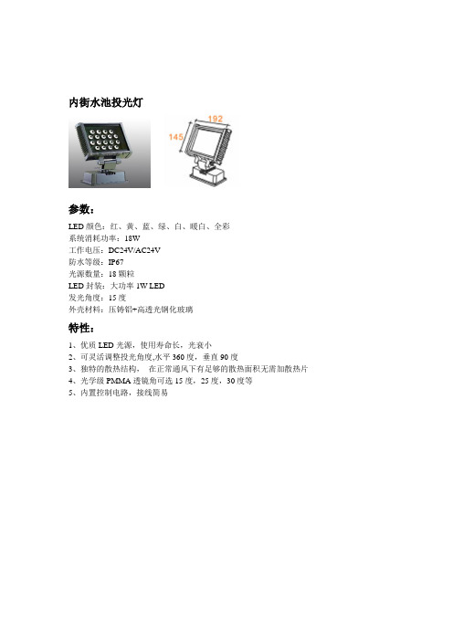
内街水池投光灯
参数:
LED颜色:红、黄、蓝、绿、白、暖白、全彩
系统消耗功率:18W
工作电压:DC24V/AC24V
防水等级:IP67
光源数量:18颗粒
LED封装:大功率1W LED
发光角度:15度
外壳材料:压铸铝+高透光钢化玻璃
特性:
1、优质LED光源,使用寿命长,光衰小
2、可灵活调整投光角度,水平360度,垂直90度
3、独特的散热结构,在正常通风下有足够的散热面积无需加散热片
4、光学级PMMA透镜角可选15度,25度,30度等
5、内置控制电路,接线简易
护栏管
参数:
LED颜色:全彩
系统消耗功率:12W
工作电压:DC12V
防水等级:IP65
光源数量:144颗粒(R48、G48、B48) LED封装:草帽F5
发光角度:120度
外壳材料:乳白PC+铝合金底座
特性:
1、优质LED光源,使用寿命长,光衰小
2、采用恒流驱动
3、环境温度:-20ºC ~~45ºC
4、可实现多种变化效果
LED幕墙点光圆RGB
a.应用范围:
·室内外动度效果显示
·高层建筑、广告显示
·桥梁建筑等地面
·酒吧舞台、大楼外立面
b.产品特点:
·颜色丰富、变化出不同的亮度·绚烂夜店、喷泉水舞
·耗电省、多色彩
·环保、安全、易施工
C.LED幕墙点光圆灯技术参数:
e.电气规格。
LED射灯灯系列说明书_图文(精)

输入电压In put voltage : AC90-240V 光源LED qua ntity : LED 9 pcs 灯体功率power : 18W 色温Color temperature : 3000k/4200k/6400k输出光通量Luminous flux : 1350Lm 环境温度Ambient temperature : -20°C -+40°C 灯体效率Efficiency : 75Lm/W 寿命Lifetime : >30000 hours 发光角度Beam angle : 28/38 ° 外观颜色Fixture color : 银色/金Silver/Golde n103.2mm显色指数Ra :138mm158.5mm138mm158.5mm138mm103.2mm 158.5mm158.5mm158.5mm75-90产品尺寸图Ptoduct Size :产品特点Characteristics : 材质工艺:采用导热性极高的铝合金及专利结构技术设ELU99卜A103 2mm◎使用光源:一律采用低光衰的大功率的LED作为光源,以确保其长寿命、节能、高效、环保的特点防触电等级:11级配光方式:光面(强光玻珠面(半强光雾面(柔光配光种类:28 738。
安装地点:室内Material tech ni cs:Aviati on alumi num of hingh heat con du- ctivity and pate ned configuration technics lighting source: Low light attenuation and high power LED to make sure long lifetime, energy-saving , high efficiency and pro-environment Antielectric shock rate: Class IILens surface: Tran spare nt surface(high bright bead surface (bright fog-effect surface(lambe ncy Beam an gle: 28/38 °installati on place: in door应用场所Application :适用于汽车展示、珠宝首饰、高档服装、专业橱窗等重点照明场所,是替代传统卤素灯和金卤灯的理想光源Suitable for carjewelry and cloth ing display;ca n be in show windon s,shop coun ters and other lighting locations It is the ideal lighting source for the replacement market of conven ti onal haloge n lamps and metal halide lamps技术参数Technic Parameters :ZB-D901-18Professio nalLEDLight in gE nterprise 專業LED 照明生產商en vir onmen tal en ergyU n R e gi s t e r e d输入电压In put voltage : AC90-240V 光源LED qua ntity : LED 12 pcs 灯体功率power : 12W 色温Color temperature : 3000k/4200k/6400k输出光通量Luminous flux : 970Lm 环境温度Ambient temperature : -20°C -+40°C 灯体效率Efficiency : 80Lm/W 寿命Lifetime : >30000 hours 发光角度Beam angle : 28/38 °外观颜色Fixture color : 银色Silver显色指数Ra :75-90产品尺寸图Ptoduct Size :产品特点Characteristics : 材质工艺:采用导热性极高的铝合金及专利结构技术设计生产使用光源:一律采用低光衰的大功率的LED作为光源,以确保其长寿命、节能、高效、环保的特点防触电等级:11级配光方式:光面(强光玻珠面(半强光雾面(柔光配光种类:28 738。
LED灯珠全参数介绍
LED灯珠参数介绍SMT2015-11-5三星大功率1—3WLED灯珠商品名称:SAMSUNG 1-3W灯珠商品编号:SPHWHTCN303主要参数:光通量: ≥110LM色温: 暧白(2800-3200),正白(3700K-4500K),冷白(5000K-7500K)发光角度: 120°电压: 3.0-3.4V电流:≥350MA商品尺寸: 3.5 * 3.5 * t 2.1 mmLED灯珠参数介绍:1、亮度LED的亮度不同,价格不同。
灯杯:一般亮度为60-70lm;球泡灯:一般亮度为80-90lm.注:1W亮度为60-110lm3W亮度最高可达240lm5W-300W是集成芯片,用串/并联封装,主要看多少电流,电压,几串几并。
1W红光,亮度一般为30-40lm;1W绿光,亮度一般为60-80lm;1W黄光,亮度一般为30-50lm;1W蓝光,亮度一般为20-30lm.LED透镜:一次透镜一般用PMMA、PC、光学玻璃、硅胶(软硅胶,硬硅胶)等材料。
角度越大出光效率越高,用小角度的LED透镜,光线要射得远的。
2、抗静电能力抗静电能力强的LED,寿命长,因而价格高。
通常抗静电大于700V的LED才能用于LED灯饰。
3、波长波长一致的LED,颜色一致,如要求颜色一致,则价格高。
没有LED分光分色仪的生产商很难生产色彩纯正的产品。
大功率LED灯珠详细参数及点光源选择技巧白光分暖色(色温2700-4000K),正白(色温5500-6000K),冷白(色温7000K以上)欧洲人比较喜欢暖白红光:波段600-680,其中620,630主要用于舞台灯,690接近红外线蓝光:波段430-480,其中460,465舞台灯用的较多。
绿光:波段500-580,其中525,530舞台灯用的较多。
4、漏电电流LED是单向导电的发光体,如果有反向电流,则称为漏电,漏电电流大的LED,寿命短,价格低。
5、发光角度用途不同的LED其发光角度不一样。
Performer 18 RGBWA用户手册说明书
PERFORMER 18 RGBWAOrder code: LEDJ252AUSER MANUALWARNINGFOR YOUR OWN SAFETY, PLEASE READ THIS USER MANUAL CAREFULLYBEFORE YOUR INITIAL START-UP!SAFETY INSTRUCTIONSEvery person involved with the installation, operation & maintenance of thisequipment should:- Be competent- Follow the instructions of this manualBefore your initial start-up, please make sure that there is no damage caused during transportation. Should there be any, consult your dealer and do not use theequipment.To maintain the equipment in good working condition and to ensure safe operation, it is necessary for the user to follow the safety instructions and warning notes written in this manual.Please note that damages caused by user modifications to this equipment are notsubject to warranty.IMPORTANT:The manufacturer will not accept liability for any resulting damages causedby the non-observance of this manual or any unauthorised modification to the equipment.• Never let the power-cable come into contact with other cables. Handle the power-cable and all mains voltage connections with particular caution!• Never remove warning or informative labels from the equipment.• Do not open the equipment and do not modify the equipment.• Do not connect this equipment to a dimmer-pack.• Do not switch the equipment on and off in short intervals, as this will reduce thesystem’s life.• Only use the equipment indoors.• Do not expose to flammable sources, liquids or gases.• Always disconnect the power from the mains when equipment is not in use or beforecleaning! Only handle the power-cable by the plug. Never pull out the plug by pulling the power-cable.• Make sure that the available voltage is between 100~240V.• Make sure that the power-cable is never crimped or damaged. Check the equipment and the power-cable periodically.• If the equipment is dropped or damaged, disconnect the mains power supply immediately.Have a qualified engineer inspect the equipment before operating again.• If the equipment has been exposed to drastic temperature fluctuation (e.g. aftertransportation), do not switch it on immediately. The arising condensation might damage the equipment. Leave the equipment switched off until it has reached room temperature.• If your product fails to function correctly, discontinue use immediately. Pack the unitsecurely (preferably in the original packing material), and return it to your Prolight dealer for service.• Only use fuses of same type and rating.• Repairs, servicing and power connection must only be carried out by a qualifiedtechnician. THIS UNIT CONTAINS NO USER SERVICEABLE PARTS.• WARRANTY; One year from date of purchase.OPERATING DETERMINATIONSIf this equipment is operated in any other way, than those described in this manual,the product may suffer damage and the warranty becomes void.Incorrect operation may lead to danger e.g.: short-circuit, burns, electric shocks,lamp failure etc.Do not endanger your own safety and the safety of others!Incorrect installation or use can cause serious damage to people and property.You should find inside the LEDJ carton the following items :1, 18 RGBWA unit2, Instruction manualSetup:Operating InstructionsThe Performer 18 RGBWA is a DMX-512 controllable, full RGBWA colour mixing Par Can made up of high efficiency LED’s. There are five colour groups (red, green, blue, white and amber) whose intensity can be controlled individually allowing the creation of an unlimited range of colours. The Performer 18 RGBWA will operate in stand-alone, master/slave, sound activated and DMX-512 control modes.DMX mode:To select DMX mode, press the “MENU” button to show “D001” on the display. Now press the “ENTER” button and use the “UP” and “DOWN” buttons to set the DMX address from 001-512. When you have finished setting the desired DMX address press the “ENTER” button.DMX channel mode:To select channel mode, press the “MENU” button to show “5ch” or “9ch” on the display. Now press the “ENTER” button and use the “UP” and “DOWN” buttons to select between the 5 or 9 channel modes. To confirm your choice, press the “ENTER” button.Performer 18 RGBWA Featuring 5-in-1 LED engine and produces no multi-coloured shadowing thanks to its 18 x 10W RGBWA LEDs, the Alu Performer Par punches out astonishing levels of colour ideal for uplighting in large venues, general stage wash and illumination.• 18 x 10W RGBWA LEDs• Beam angle: 40°• DMX channels: 5 or 9 selectable•sound active and master/slave modes• Bracket allows for multiple rigging orfloor standing applications• 4 push button menu with LED display• 3-Pin XLR in/out sockets• Captive power connection• Fan cooled• Power consumption: 190W• Power supply: 100~240V, 50/60Hz• Dimensions: 255 x 297 x 325mm• Weight: 2.6kgColour change modeTo select the colour change mode, press the “MENU” button to show “CC00” on the display. Now press the “ENTER” button and use the “UP” and “DOWN” buttons to adjust the speed of the colour change. To confirm your choice, press the “ENTER” button.Colour fade modeTo select the colour fade mode, press the “MENU” button to show “CP00” on the display. Now press the “ENTER” button and use the “UP” and “DOWN” buttons to adjust the speed of the colour fade. To confirm your choice, press the “ENTER” button.Please note that in this mode the unit will run through both static colour fade and colour fade in/out modes. To access the modes individually, please set the unit into DMX mode and see the DMX chart overleaf.Auto built-in programmes modeTo select the Auto Built-in programme mode, press the “MENU” button to show “dE00” on the display. Now press the “ENTER” button and use the “UP” and “DOWN” buttons to adjust the speed. To confirm your choice, press the “ENTER” button.Please note that in this mode the unit will run through all of the colour change and colour fade modes. To access the modes individually, please set the unit into DMX mode and see the DMX chart overleaf.Sound active modeTo select the Sound active mode, press the “MENU” button to show “bEbE” on the display. Now press the “ENTER” and the unit will respond to the beat of the music.Static colour modeRedTo adjust the brightness of the red LEDs, press the “MENU” button to show “R255” on the display. Now press use the “UP” and “DOWN” buttons to adjust the brightness from 000-255.To confirm your choice, press the “ENTER” button. Note: 000 = off, 255 = full on.GreenTo adjust the brightness of the green LEDs, press the “MENU” button to show “G255” on the display. Now press use the “UP” and “DOWN” buttons to adjust the brightness from 000-255.To confirm your choice, press the “ENTER” button. Note: 000 = off, 255 = full on.BlueTo adjust the brightness of the blue LEDs, press the “MENU” button to show “B255” on the display. Now press use the “UP” and “DOWN” buttons to adjust the brightness from 000-255.To confirm your choice, press the “ENTER” button. Note: 000 = off, 255 = full on.WhiteTo adjust the brightness of the white LEDs, press the “MENU” button to show “U255” on the display. Now press use the “UP” and “DOWN” buttons to adjust the brightness from 000-255.To confirm your choice, press the “ENTER” button. Note: 000 = off, 255 = full on.AmberTo adjust the brightness of the white LEDs, press the “MENU” button to show “Y255” on the display. Now press use the “UP” and “DOWN” buttons to adjust the brightness from 000-255.To confirm your choice, press the “ENTER” button. Note: 000 = off, 255 = full on.Master/slave mode To set the unit as a master, simply select any of the above modes and set the slave units into DMX mode, address 001. The slave units will now follow in sequence with the master unit.DMX-512: • DMX (Digital Multiplex) is a universal protocol used as a form of communication between intelligent fixtures and controllers. A DMX controller sends DMX data instructions from thecontroller to the fixture. DMX data is sent as serial data that travels from fixture to fixture via the DATA “IN” and DATA “OUT” XLR terminals located on all DMX fixtures (most controllers only have a data “out” terminal).DMX Linking: • DMX is a language allowing all makes and models of different manufactures to be linked together and operate from a single controller, as long as all fixtures and the controller are DMX compliant. To ensure proper DMX data transmission, when using several DMX fixtures try to use theshortest cable path possible. The order in which fixtures are connected in a DMX line does not influence the DMX addressing. For example; a fixture assigned to a DMX address of 1 may be placed anywhere in the DMX line. When a fixture is assigned a DMX address of 1, the DMXcontroller knows to send DATA assigned to address 1 to that unit, no matter where it is located in the DMX chain.5 Channel:9 Channel:DMX chart:ChannelValue Function 1000-255Master dimmer 2000-255Strobe (Slow to fast)3000-049Manual DMX 050-099Colour change 100-149Colour fade 150-199Colour fade in/out 200-255Sound active 4000-255Chase/fade speed 5000-255Red 6000-255Green 7000-255Blue 8000-255White 9000-004AmberChannelValue Function 1000-255Red 2000-255Green 3000-255Blue 4000-255White 5000-004AmberPerformer 18 RGBWADATA Cable (DMX cable) requirements (for DMX operation):• The Performer Series can be controlled via DMX-512 protocol. The DMX address can be set on。
3wled灯珠参数
3wled灯珠参数
3W LED灯珠:高亮度、高效能的照明选择
随着科技的不断进步,LED灯珠已经成为了照明行业的主流选择。
而在LED灯珠中,3W LED灯珠则是一种高亮度、高效能的照明选择。
本文将从以下几个方面来介绍3W LED灯珠的参数和特点。
3W LED灯珠的亮度非常高。
它可以发出高达300流明的光亮,相当于传统白炽灯的30瓦。
这意味着,使用3W LED灯珠的灯具可以在保持相同亮度的情况下,大大降低能耗。
这也是为什么3W LED灯珠被广泛应用于商业和家庭照明中的原因之一。
3W LED灯珠的效能也非常高。
它的效能可以达到100流明/瓦以上,这意味着它可以将更多的电能转化为光能,而不是热能。
这也是为什么3W LED灯珠比传统白炽灯更加节能的原因之一。
除此之外,3W LED灯珠还有其他一些特点。
例如,它的寿命非常长,可以达到50000小时以上。
这意味着,使用3W LED灯珠的灯具可以减少更换灯泡的频率,从而降低维护成本。
此外,3W LED 灯珠还可以发出不同颜色的光,例如白光、暖光、冷光等,可以满足不同场合的照明需求。
3W LED灯珠是一种高亮度、高效能的照明选择。
它的亮度和效能都非常高,可以大大降低能耗。
此外,它的寿命也非常长,可以减少维护成本。
因此,如果您正在寻找一种高性能的照明选择,3W
LED灯珠将是一个不错的选择。
3535RGB规格书(中文)C16-A
Prepared by: calvin chai
Page: 5 of 8
Technical Data Sheet 3535 Top View LEDs
■ 使用说明
1. 储存 1-1. 开封前请先检查包装袋有无漏气,开包后检查湿度标示卡 20%RH 标示区有无由蓝色变为粉红色.如
漏气或变色现象,请联系厂家重新烘烤使用。 1-2. 打开包装后,在温度低于 30℃ ,湿度低于 60%RH 的情况下,且开封到焊接完成控制在 12H。
7. 焊接指导 1.手工焊接 7-1. 如使用烙铁手工焊接,建议使用小于 25W 的电烙铁,烙铁温度必须控制在 315℃以下,焊接时间 需控制在 3 秒以内,且每个电极只能焊接一次。
Device No. : LDS-3535 -001
Rev.: A
Prepared date: 2016-12-24
Prepared by: calvin chai
5 低温储存 6 常温点亮老化 7 高温高湿
TEMP : -40℃ TEMP : 25℃ IF = 20*3mA 85℃ / 85% RH
10 秒 300 回合 300 回合 1000 小时 1000 小时 1000 小时 1000 小时
22 PCS
0/1
22 PCS
0/1
22 PCS 22 PCS 22 PCS
Iv≦
0/1
Ivt*0.5
or
Vf≦U 0/1 or
Vf≧L
0/1
22 PCS
0/1
22 PCS
0/1
Notes:
Ivt: 信赖性测试前 Iv 值; Iv: 完成信赖性测试后 Iv 值; U:规格上限值 L:规格下限值
ProLight Phenix 3535 4W 绿色高功率LED灯光数据表说明书

ProLight PK2N-4LME-HSDLA 4W Crimson Power LED Technical Datasheet Version: 1.4Features‧100% foot print compatible with CreeXP-C / XP-E / XP-G‧Best thermal material solution of the world ‧Best Moisture Sensitivity:JEDEC Level 1‧RoHS compliant Main Applications ‧Accent and effect lighting‧Horticultural LightingIntroduction‧ProLight Phenix3535, is one of the smallest high power LED footprint availableby ProLight Opto, has offered extended solid-state lighting design possibilities.ProLight Phenix3535 is designed with ProLight own Patents and using copperleadframe, the best thermal material of the world.‧Phenix3535 qualifies as the JEDEC Level 1 MSL sensitivity level and suitable forSMD process, Pb_free reflow soldering capability, and full compliance with EUReduction of Hazardous Substances (RoHS) legislation.2020/12No. 89, Xiyuan Rd., Zhongli City, Taoyuan County 320,Emitter Mechanical DimensionsNotes:1. The cathode side of the device is denoted by the chamfer on the part body.2. Electrical insulation between the case and the board is required. Do not electrically connecteither the anode or cathode to the slug.3. Drawing not to scale.4. All dimensions are in millimeters.5. Unless otherwise indicated, tolerances are ±0.10mm.6. Please do not solder the emitter by manual hand soldering, otherwise it will damage the emitter.7. Please do not use a force of over 0.3kgf impact or pressure on the lens of the LED, otherwiseit will cause a catastrophic failure.*The appearance and specifications of the product may be modified for improvement without notice.2No. 89, Xiyuan Rd., Zhongli City, Taoyuan County 320,Flux Characteristics, T J= 25°CPart Number EmitterRadiometric Power (mW)PPF (μmol/s) @700mARefer@350mARefer@1000mA@700mARefer@350mARefer@1000mA Min.Typ.Typ.Typ.Typ.Typ.Typ.PK2N-4LME-HSDLA89010005001400 5.44 2.747.70●ProLight maintains a tolerance of ±7% on flux and power measurements.●Please do not drive at rated current more than 1 second without proper heat sink.ThermalForward Voltage VF(V)Resistance@700mA Refer @350mA Refer @1000mA Junction to Color Min.Typ.Max.Typ.Typ.Slug (°C/ W) Crimson 1.75 2.15 2.75 1.97 2.30 3.5●ProLight maintains a tolerance of ±0.1V for Voltage measurements.Electrical Characteristics, T J= 25°COptical Characteristics at 700mA, T J= 25°CTotalincluded ViewingAngle AngleRadiationColor Peak Wavelength λP,(degrees)(degrees)Pattern Min.Typ.Max.θ0.90V 2 θ1/2Lambertian Crimson【1】650 nm660 nm670 nm160140●ProLight maintains a tolerance of ±1nm for dominant wavelength measurements.●【1】The peak wavelength of 660nm should contain the dominant wavelength of around 640nm.No. 89, Xiyuan Rd., Zhongli City, Taoyuan County 320,3No. 89, Xiyuan Rd., Zhongli City, Taoyuan County 320, Absolute Maximum Ratings4ParameterCrimsonDC Forward Current (mA)1000Peak Pulsed Forward Current (mA)1500 (less than 1/10 duty cycle@1KHz)ESD Sensitivity±4000V (Class III)(HBM per MIL-STD-883E Method 3015.7)LED Junction Temperature 120°C Operating Board Temperature -40°C -105°Cat Maximum DC Forward Current Storage Temperature -40°C -120°C Soldering Temperature JEDEC 020c 260°CAllowable Reflow Cycles 3Reverse VoltageNot designed to be driven in reverse biasRadiometric Power Bin Structure at 700mAColorBin Code Radiometric Power (mW)PPF (μmol/s)PPF/W (μmol/J)Available Min.Max.Min.Max.Typ.Color BinsCrimsonV1890925 4.84 5.03 3.28All V2925960 5.03 5.22 3.41All W1960995 5.22 5.41 3.53AllW29951035 5.41 5.63 3.67【1】X110351075 5.63 5.85 3.81【1】X2107511205.856.093.97【1】●ProLight maintains a tolerance of ±7% on flux and power measurements.●The flux bin of the product may be modified for improvement without notice. ●【1】The rest of color bins are not 100% ready for order currently. Please ask for quote and order possibility.No. 89, Xiyuan Rd., Zhongli City, Taoyuan County 320, ColorBin CodeMinimum Peak Maximum Peak Wavelength (nm)Wavelength (nm)Crimson1650655265566036606654665670●ProLight maintains a tolerance of ±1nm for peak wavelength measurements.Peak Wavelength Bin Structure at 700mA5Forward Voltage Bin Structure at 700mAColorBin CodeMinimum Voltage (V)Maximum Voltage (V)CrimsonA 1.75 2.00B 2.00 2.25 D 2.25 2.50 E2.502.75●ProLight maintains a tolerance of ±0.1V for Voltage measurements.Note: Although several bins are outlined, product availability in a particular bin varies by production runand by product performance. Not all bins are available in all colors.No. 89, Xiyuan Rd., Zhongli City, Taoyuan County 320, 0.00.20.40.60.8 1.0350400450500550600650700750800R e l a t i v e S p e c t r a l P o w e r D i s t r i b u t i o nWavelength (nm)1. Crimson6Color Spectrum, T J = 25°CNo. 89, Xiyuan Rd., Zhongli City, Taoyuan County 320, 8084889296100104108020406080100120R e l a t i v e F o r w a r d V o l t a g e (%)Junction Temperature, T J (℃)020406080100120140020406080100120R e l a t i v e L i g h t O u t p u t (%)Junction Temperature, T J (℃)7Junction Temperature Relative Characteristics1. Junction Temperature vs. Relative Light Output at 700mA2. Junction Temperature vs. Relative Forward Voltage at 700mANo. 89, Xiyuan Rd., Zhongli City, Taoyuan County 320, 1.52.02.53.03.54.04.55.0020040060080010001200P P F /WForward Current (mA)0.01.02.03.04.05.06.07.08.0020040060080010001200P P FForward Current (mA)0.00.20.40.60.81.01.21.41.620040060080010001200R e l a t i v e R a d i o m e t r i c P o w e rForward Current (mA)200400600800100012000.00.5 1.0 1.5 2.0 2.5 3.0 3.5 4.0A v e r a g e F o r w a r d C u r r e n t (m A )Forward Voltage (V)8Forward Current Characteristics, T J = 25°CNo. 89, Xiyuan Rd., Zhongli City, Taoyuan County 320, 0200400600800100012000255075100125150F o r w a r d C u r r e n t (m A )Ambient Temperature (℃)R θJ-A = 15°C/W R θJ-A = 20°C/W R θJ-A = 10°C/W1. Crimson (T JMAX = 120°C)Ambient Temperature vs. Maximum Forward Current9Typical Representative Spatial Radiation PatternSoak RequirementsLevel Floor Life Standard Accelerated Environment Time Conditions Time (hours)Conditions Time (hours)Conditions1Unlimited≤30°C /168 +5/-085°C /NA NA 85% RH85% RH●The standard soak time includes a default value of 24 hours for semiconductor manufature'sexposure time (MET) between bake and bag and includes the maximum time allowed out ofthe bag at the distributor's facility.●Table below presents the moisture sensitivity level definitions per IPC/JEDEC's J-STD-020C.Soak Requirements Level Floor Life Standard Accelerated Environment Time Conditions Time (hours)Conditions Time (hours)Conditions1Unlimited≤30°C /168 +5/-085°C /NA NA 85% RH85% RH2 1 year≤30°C /168 +5/-085°C /NA NA 60% RH60% RH2a 4 weeks≤30°C /696 +5/-030°C /120 +1/-060°C / 60% RH60% RH60% RH3168 hours≤30°C /192 +5/-030°C /40 +1/-060°C / 60% RH60% RH60% RH472 hours≤30°C /96 +2/-030°C /20 +0.5/-060°C / 60% RH60% RH60% RH548 hours≤30°C /72 +2/-030°C /15 +0.5/-060°C / 60% RH60% RH60% RH5a24 hours≤30°C /48 +2/-030°C /10 +0.5/-060°C / 60% RH60% RH60% RH6Time on Label≤30°C / Time on Label30°C /NA NA (TOL)60% RH(TOL)60% RHMoisture Sensitivity Level -JEDEC Level 1No. 89, Xiyuan Rd., Zhongli City, Taoyuan County 320,10No. 89, Xiyuan Rd., Zhongli City, Taoyuan County 320, Stress TestStress Conditions Stress Duration Failure CriteriaRoom Temperature 25°C, I F = max DC (Note 1)1000 hours Note 2Operating Life (RTOL)Wet High Temperature 85°C/60%RH, I F = max DC (Note 1)1000 hours Note 2Operating Life (WHTOL)Wet High Temperature 85°C/85%RH, non-operating1000 hours Note 2Storage Life (WHTSL)High Temperature 110°C, non-operating 1000 hours Note 2Storage Life (HTSL)Low Temperature -40°C, non-operating 1000 hours Note 2Storage Life (LTSL)Non-operating-40°C to 120°C, 30 min. dwell,200 cyclesNote 2Temperature Cycle (TMCL)<5 min. transferMechanical Shock 1500 G, 0.5 msec. pulse, Note 35 shocks each 6 axis Natural Drop On concrete from 1.2 m, 3X Note 3Variable Vibration10-2000-10 Hz, log or linear sweep rate,Note 3Frequency20 G about 1 min., 1.5 mm, 3X/axisSolder Heat Resistance260°C ±5°C, 10 sec.Note 3(SHR)SolderabilitySteam age for 16 hrs., then solder dipSolder coverageat 260°C for 5 sec.on leadNotes:1. Depending on the maximum derating curve.2. Criteria for judging failureItemTest Condition Criteria for Judgement Min.Max.Forward Voltage (V F )I F = max DC --Initial Level x 1.1Luminous Flux or I F = max DC Initial Level x 0.7--Radiometric Power (ΦV )Reverse Current (I R )V R = 5V--50 μA* The test is performed after the LED is cooled down to the room temperature.3. A failure is an LED that is open or shorted.11Qualification Reliability TestingNo. 89, Xiyuan Rd., Zhongli City, Taoyuan County 320, TYPE A.12Recommended Solder Pad DesignStandard Emitter ●All dimensions are in millimeters.●Electrical isolation is required between Slug and Solder Pad.TYPE B.No. 89, Xiyuan Rd., Zhongli City, Taoyuan County 320, 13Reflow Soldering ConditionProfile FeatureSn-Pb Eutectic Assembly Pb-Free Assembly Average Ramp-Up Rate 3°C / second max.3°C / second max.(T Smax to T P )Preheat–Temperature Min (T Smin )100°C 150°C –Temperature Max (T Smax )150°C 200°C –Time (t Smin to t Smax )60-120 seconds 60-180 seconds Time maintained above:–Temperature (T L )183°C 217°C –Time (t L )60-150 seconds60-150 secondsPeak/Classification Temperature (T P )240°C 260°C Time Within 5°C of Actual Peak 10-30 seconds 20-40 seconds Temperature (t P )Ramp-Down Rate6°C/second max.6°C/second max.Time 25°C to Peak Temperature6 minutes max.8 minutes max.●We recommend using the M705-S101-S4 solder paste from SMIC (Senju Metal Industry Co., Ltd.) for lead-free soldering.●Do not use solder pastes with post reflow flux residue>47%. (58Bi-42Sn eutectic alloy, etc) This kind of solder pastes may cause a reliability problem to LED.●All temperatures refer to topside of the package, measured on the package body surface.●Repairing should not be done after the LEDs have been soldered. When repairing is unavoidable, a double-head soldering iron should be used. It should be confirmed beforehand whether the characteristics of the LEDs will or will not be damaged by repairing.●Reflow soldering should not be done more than three times.●When soldering, do not put stress on the LEDs during heating.●After soldering, do not warp the circuit board.t 25°C to Peakt S PreheatTimeT e m p e r a t u r eCritical Zone T L to T PRamp-upRamp-downT SmaxT Smint Pt LT PT L25IPC-020cNotes:1. Drawing not to scale.2. All dimensions are in millimeters.3. Unless otherwise indicated, tolerances are ±0.10mm.14 No. 89, Xiyuan Rd., Zhongli City, Taoyuan County 320,No. 89, Xiyuan Rd., Zhongli City, Taoyuan County 320, 178 ± 13 ± 0.54 ± 0.5 5 ± 0.5601316Φ 13.1 ± 0.5Φ 21 ± 0.560 ± 0.513.2 ± 0.516.2 ± 0.5515Notes:1. Empty component pockets sealed with top cover tape.2. 250, 500 and 1000 pieces per reel.3. Drawing not to scale.4. All dimensions are in millimeters.No. 89, Xiyuan Rd., Zhongli City, Taoyuan County 320, 16Precaution for UseHandling of Silicone Lens LEDsNotes for handling of silicone lens LEDs●Please do not use a force of over 0.3kgf impact or pressure on the silicone lens, otherwise it will cause a catastrophic failure.●The LEDs should only be picked up by making contact with the sides of the LED body.●Avoid touching the silicone lens especially by sharp tools such as Tweezers.●Avoid leaving fingerprints on the silicone lens.●Please store the LEDs away from dusty areas or seal the product against dust.●When populating boards in SMT production, there are basically no restrictions regarding the form of the pick and place nozzle, except that mechanical pressure on the silicone lens must be prevented.●Please do not mold over the silicone lens with another resin. (epoxy, urethane, etc)●StoragePlease do not open the moisture barrier bag (MBB) more than one week. This may cause the leads of LED discoloration. We recommend storing ProLight’s LEDs in a dry box after opening the MBB. The recommended storage conditions are temperature 5 to 30°C and humidity less than 40% RH. It is also recommended to return the LEDs to the MBB and to reseal the MBB.●The slug is is not electrically neutral. Therefore, we recommend to isolate the heat sink.●We recommend using the M705-S101-S4 solder paste from SMIC (Senju Metal Industry Co., Ltd.) for lead-free soldering.●Do not use solder pastes with post reflow flux residue>47%. (58Bi-42Sn eutectic alloy, etc) This kind of solder pastes may cause a reliability problem to LED.●Any mechanical force or any excess vibration shall not be accepted to apply during cooling process to normal temperature after soldering.●Please avoid rapid cooling after soldering.●Components should not be mounted on warped direction of PCB.●Repairing should not be done after the LEDs have been soldered. When repairing is unavoidable,a heat plate should be used. It should be confirmed beforehand whether the characteristics of the LEDs will or will not be damaged by repairing.●This device should not be used in any type of fluid such as water, oil, organic solvent and etc.When cleaning is required, isopropyl alcohol should be used.●When the LEDs are illuminating, operating current should be decide after considering the package maximum temperature.●The appearance, specifications and flux bin of the product may be modified for improvement without notice. Please refer to the below website for the latest datasheets./。
- 1、下载文档前请自行甄别文档内容的完整性,平台不提供额外的编辑、内容补充、找答案等附加服务。
- 2、"仅部分预览"的文档,不可在线预览部分如存在完整性等问题,可反馈申请退款(可完整预览的文档不适用该条件!)。
- 3、如文档侵犯您的权益,请联系客服反馈,我们会尽快为您处理(人工客服工作时间:9:00-18:30)。
● Feature (特 性)
● High Power LED (大功率LED) ● Package : SMT Package (贴片式外形) ●Half Angle (2Θ1/2):140° (视角:140°) ●Lens Color:Water Clear (透镜颜色:无色透明)
PART NUMBER
Max. (最大值)
R=80 G=120 B=40 R=630 G=530 B=470 R=2.50 G=3.60 B=3.60
~
~
Units (单位)
lm
nm
V
°C/W mV/°C
Viewing Angle [1](发光角度)
2Θ1/2
~
140
~
Deg
Reverse Current(反向漏电流)
IR
回流焊 gfedc 铅焊料 120~150℃ 120Sec Max
240℃ Max 10 Sec Max
无铅焊料 180~200℃ 120 Sec Max
REV
PAGE
DATE
L001
9/2
2012-8-28
E-mail:lyhua@
深圳市光华士科技有限公司
ShenZhen Lightwells Opto-Electronic CO .,Ltd
■Photoelectric parameters(光 电 参 数);(At TA=25°C)
深圳市光华士科技有限公司
ShenZhen Lightwells Opto-Electronic CO .,Ltd
Admit specification (承认规格书)
CUSTOMER (客户名称):
PART NO (产品型号):
DESCRIPTION (产品描述):
DATE (日期):
GHS-PL2RGB43B5 5W/RGB
深圳市光华士科技有限公司
ShenZhen Lightwells Opto-Electronic CO .,Ltd
■Forward current - voltage curve(正向电流-电压曲线图)
Forward Current(mA)
Forward current - voltage curve
Peak Forward Current [2](顺向脉冲电流)
IF(Peak)
1500
10
μA
Units (单位)
W
mA
mA
LED Junction Temperature(结点温度)
TJ
120
°C
Reverse Voltage(反向电压)
VR
5
V
Operating Temperature Range(工作温度)
0.4
0
0
100 200 300 400
IF-Forward Current(mA)
PART NUMBER
GHS-PL2RGB43B5
REV L001
PAGE
DATE
9/4
2012-8-28
E-mail:lyhua@
深圳市光华士科技有限公司
■Space radiation curve(空间辐射曲线图)
Space radiation curve (空间辐射曲线图)
■Angle figure(发光角度图)
Angular Displacement (Degrees)
Angle figure
(
)
20 10 30 40
50
0 10 20 30 40
ESD
3000V HBM
Notes:
[1]. Tolerance Θ:10%
(Θ公差为10%)
[2].1/10 Duty Cycle 0.1ms Pulse Width. (脉冲宽度0.1ms,占空比1/10)
PART NUMBER
GHS-PL2RGB43B5
PAGE
DATE
9/5
2012-8-28
E-mail:lyhua@
深圳市光华士科技有限公司
ShenZhen Lightwells Opto-Electronic CO .,Ltd
深圳市光华士科技有限公司
ShenZhen Lightwells Opto-Electronic CO .,Ltd
TOPR
-35°C To +60°C
Storage Temperature Range(储存温度)
TSTG
-40°C To +100°C
Manual Solding Temperature(手工焊接温度)
TSOL
350°C± 20°C For 3 Seconds
ESD Sensitivity(抗静电能力)
(-
)
110
Relative Luminous Intensity( %)
100
10
1 -60 -40 -20 0 20 40 60 80 100
Ambient Temperature Ta( °c)
PART NUMBER
GHS-PL2RGB43B5
REV L001
■ Package Dimensions (外观尺寸)
■ Product pictures (实物图片)
■ Current direction(电流方向)
共阳
-
-
+
-
■Notes(注释):
1. All dimensions are in millimeters. (所有尺寸以毫米为单位) 2. Tolerance is ±0.25 unless otherwise noted (未标注公差为:±0.25)
50
60
60
70
70
80
80
90
1.0 0.9 0.8 0.7 0.6 0.5 0.4 0.3 0.2 0.1 0
90
0.1 0.2 0.3 0.4 0.5 0.6 0.7 0.8 0.9 1.0
PART NUMBER
GHS-PL2RGB43B5
REV L001
地址:中国 深圳 光明新区 公明镇合水口新村西区一排四栋 座机号码:0755-32971985 传真号码:0755-27821289
15814007835 E-mail:lyhua@
深圳市光华士科技有限公司
ShenZhen Lightwells Opto-Electronic CO .,Ltd
■Forward current - luminous intensity curve(正向电流-发光强度图)
Luminous Flux Relative Value at IF=350mA
Forward current - luminous intensity curve
(
-
)
1.2
1.0
0.8
0.6
PART NUMBER
GHS-PL2RGB43B5
REV L001
PAGE
DATE
9/7
2012-8-28
E-mail:lyhua@
深圳市光华士科技有限公司
ShenZhen Lightwells Opto-Electronic CO .,Ltd
(
)
RELATIVE INTENSITY vs WAVELENGTH
1.0
ultraviolet
Blue
green
yellow red
0.75
Relative Radiant Intensity
0.5
0.25
0 350 400 450 500 550 600 650 700 750 Wavelength(nm)
Parameter(参数) Luminous Intensity(光通量) Spectral Line Half-Width(波长) Forward Voltage(正向压降) Thermal Resistance Junction To Board (热 阻) Temperature coefficient (温度系数)
PAGE
DATE
9/6
2012-8-28
E-mail:lyhua@lantuபைடு நூலகம்.org
深圳市光华士科技有限公司
ShenZhen Lightwells Opto-Electronic CO .,Ltd
ShenZhen Lightwells Opto-Electronic CO .,Ltd
■Chromaticity Coordinate (色度坐标图)
Symbol (符号)
Φ
Δλ
VF
RΘJ-B
Conditions (测试条件)
R=600mA G=550mA B=550mA
Min. (最小值)
R=40 G=80 B=20 R=620 G=520 B=460 R=2.00 G=3.00 B=3.00
−−
∆VF/∆T
~
Avg. (平均值)
~
~
~
12 −2
VR=5V
~
~
Notes : 1. Luminous flux is measured with an accuracy of ±10%(光通量测量精度±10%) T is measured with an accuracy of ± 100K(色温测量精度±100K) 3. wavelength is measured with an accuracy of ±1nm(波长测量精度±1nm) 4.The forward voltage is measured with an accuracy of ±0.1V|(正向电压测量的准确性可达±0.1 v )
