外文翻译2
图像处理外文翻译 (2)
附录一英文原文Illustrator software and Photoshop software difference Photoshop and Illustrator is by Adobe product of our company, but as everyone more familiar Photoshop software, set scanning images, editing modification, image production, advertising creative, image input and output in one of the image processing software, favored by the vast number of graphic design personnel and computer art lovers alike.Photoshop expertise in image processing, and not graphics creation. Its application field, also very extensive, images, graphics, text, video, publishing various aspects have involved. Look from the function, Photoshop can be divided into image editing, image synthesis, school tonal color and special effects production parts. Image editing is image processing based on the image, can do all kinds of transform such as amplifier, reducing, rotation, lean, mirror, clairvoyant, etc. Also can copy, remove stain, repair damaged image, to modify etc. This in wedding photography, portrait processing production is very useful, and remove the part of the portrait, not satisfied with beautification processing, get let a person very satisfactory results.Image synthesis is will a few image through layer operation, tools application of intact, transmit definite synthesis of meaning images, which is a sure way of fine arts design. Photoshop provide drawing tools let foreign image and creative good fusion, the synthesis of possible make the image is perfect.School colour in photoshop with power is one of the functions of deep, the image can be quickly on the color rendition, color slants adjustment and correction, also can be in different colors to switch to meet in different areas such as web image design, printing and multimedia application.Special effects production in photoshop mainly by filter, passage of comprehensive application tools and finish. Including image effects of creative and special effects words such as paintings, making relief, gypsum paintings, drawings, etc commonly used traditional arts skills can be completed by photoshop effects. And all sorts of effects of production aremany words of fine arts designers keen on photoshop reason to study.Users in the use of Photoshop color function, will meet several different color mode: RGB, CMY K, HSB and Lab. RGB and CMYK color mode will let users always remember natural color, users of color and monitors on the printed page color is a totally different approach to create. The monitor is by sending red, green, blue three beams to create color: it is using RGB (red/green/blue) color mode. In order to make a complex color photographs on a continuous colour and lustre effect, printing technology used a cyan, the red, yellow and black ink presentation combinations from and things, reflect or absorb all kinds of light wavelengths. Through overprint) this print (add four color and create color is CMYK (green/magenta/yellow/black) yan color part of a pattern. HSB (colour and lustre/saturation/brightness) color model is based on the way human feelings, so the color will be natural color for customer computer translation of the color create provides an intuitive methods. The Lab color mode provides a create "don't rely on equipment" color method, this also is, no matter use what monitors.Photoshop expertise in image processing, and not graphics creation. It is necessary to distinguish between the two concepts. Image processing of the existing bitmap image processing and use edit some special effects, the key lies in the image processing processing; Graphic creation software is according to their own idea originality, using vector graphics to design graphics, this kind of software main have another famous company Adobe Illustrator and Macromedia company software Freehand.As the world's most famous Adobe Illustrator, feat graphics software is created, not graphic image processing. Adobe Illustrator is published, multimedia and online image industry standard vector illustration software. Whether production printing line draft of the designers and professional Illustrator, production multimedia image of artists, or Internet page or online content producers Illustrator, will find is not only an art products tools. This software for your line of draft to provide unprecedented precision and control, is suitable for the production of any small design to large complex projects.Adobe Illustrator with its powerful function and considerate user interface has occupied most of the global vector editing software share. With incomplete statistics global 37% of stylist is in use Adobe Illustrator art design. Especially the patent PostScript Adobe companybased on the use of technology, has been fully occupied professional Illustrator printed fields. Whether you're line art designers and professional Illustrator, production multimedia image of artists, or Internet page or online content producers, had used after Illustrator, its formidable will find the function and concise interface design style only Freehand to compare. (Macromedia Freehand is launched vector graphics software company, following the Macromedia company after the merger by Adobe Illustrator and will decide to continue the development of the software have been withdrawn from market).Adobe company in 1987 when they launched the Illustrator1.1 version. In the following year, and well platform launched 2.0 version. Illustrator really started in 1988, should say is introduced on the Mac Illustrator 88 version. A year after the upgrade to on the Mac version3.0 in 1991, and spread to Unix platforms. First appeared on the platform in the PC version4.0 version of 1992, this version is also the earliest Japanese transplant version. And in the MAC is used most is5.0/5.5 version, because this version used Dan Clark's do alias (anti-aliasing display) display engine is serrated, make originally had been in graphic display of vector graphics have a qualitative leap. At the same time on the screen making significant reform, style and Photoshop is very similar, so for the Adobe old users fairly easy to use, it is no wonder that did not last long, and soon also popular publishing industry launched Japanese. But not offering PC version. Adobe company immediately Mac and Unix platforms in launched version6.0. And by Illustrator real PC users know is introduced in 1997, while7.0 version of Mac and Windows platforms launch. Because the 7.0 version USES the complete PostScript page description language, make the page text and graphics quality got again leap. The more with her and Photoshop good interchangeability, won a good reputation. The only pity is the support of Chinese 7.0 abysmal. In 1998 the company launched landmark Adobe Illustrator8.0, making version - Illustrator became very perfect drawing software, is relying on powerful strength, Adobe company completely solved of Chinese characters and Japanese language support such double byte, more increased powerful "grid transition" tool (there are corresponding Draw9.0 Corel, but the effect the function of poor), text editing tools etc function, causes its fully occupy the professional vector graphics software's supremacy.Adobe Illustrator biggest characteristics is the use of beisaier curve, make simpleoperation powerful vector graphics possible. Now it has integrated functions such as word processing, coloring, not only in illustrations production, in printing products (such as advertising leaflet, booklet) design manufacture aspect is also widely used, in fact has become desktop publishing or (DTP) industry default standard. Its main competitors are in 2005, but MacromediaFreehand Macromedia had been Adobe company mergers.So-called beisaier curve method, in this software is through "the pen tool" set "anchor point" and "direction line" to realize. The average user in the beginning when use all feel not accustomed to, and requires some practice, but once the master later can follow one's inclinations map out all sorts of line, and intuitive and reliable.It also as Creative Suite of software suit with important constituent, and brother software - bitmap graphics software Photoshop have similar interface, and can share some plug-ins and function, realize seamless connection. At the same time it also can put the files output for Flash format. Therefore, can pass Illustrator let Adobe products and Flash connection.Adobe Illustrator CS5 on May 17, 2010 issue. New Adobe Illustrator CS5 software can realize accurate in perspective drawing, create width variable stroke, use lifelike, make full use of paint brush with new Adobe CS Live online service integration. AI CS5 has full control of the width zoom along path variable, and stroke, arrows, dashing and artistic brushes. Without access to multiple tools and panel, can directly on the sketchpad merger, editing and filling shape. AI CS5 can handle a file of most 100 different size, and according to your sketchpad will organize and check them.Here in Adobe Illustrator CS5, for example, briefly introduce the basic function: Adobe IllustratorQuick background layerWhen using Illustrator after making good design, stored in Photoshop opens, if often pattern is in a transparent layer, and have no background ground floor. Want to produce background bottom, are generally add a layer, and then executed merge down or flatten, with background ground floor. We are now introducing you a quick method: as long as in diagram level on press the upper right version, choose new layer, the arrow in the model selection and bottom ", "background can quickly produce. However, in Photoshop 5 after the movementmerged into one instruction, select menu on the "new layer is incomplete incomplete background bottom" to finish.Remove overmuch type clothWhen you open the file, version 5 will introduce the Illustrator before Illustrator version created files disused zone not need. In order to remove these don't need in the zone, click on All Swatches palette Swatches icon and then Select the Select clause in the popup menu, and Trash Unused. Click on the icon to remove irrelevant type cloth. Sometimes you must repeat selection and delete processes to ensure that clear palette. Note that complex documents will take a relatively long time doing cleanup.Put the fabric to define the general-screeningIn Illustrator5 secondary color and process color has two distinct advantages compared to establish for easy: they provide HuaGan tonal; And when you edit the general-screening prescription, be filled some of special color objects will be automatically updated into to the new color. Because process color won't let you build tonal and provides automatic updates, you may want to put all the fabric is defined as the general-screening. But to confirm Illustrator, when you are in QuarkXPress or when PageMaker quaclrochramatic must keep their into process of color.Preferred using CMYKBecause of Illustrator7 can let you to CMYK, RGB and HSB (hue, saturation, bright) color mode, so you want to establish color the creation of carefully, you can now contains the draft with the combination of these modes created objects. When you do, they may have output various kinds of unexpected things will happen. Printing output file should use CMYK; Only if you don't use screen display manuscript RGB. If your creation draft will also be used for printing and screen display, firstly with CMYK create printing output file, then use to copy it brings As ordered the copy and modify to the appropriate color mode.Information source:" Baidu encyclopedia "附录二中文译文Illustrator软件与Photoshop软件的区别Photoshop与Illustrator都是由Adobe公司出品的,而作为大家都比较熟悉的Photoshop软件,集图像扫描、编辑修改、图像制作、广告创意,图像输入与输出于一体的图形图像处理软件,深受广大平面设计人员和电脑美术爱好者的喜爱。
人员流失问题及对策外文文献翻译2
人员流失问题及对策外文文献翻译2.5万字符人员流失问题及对策外文文献翻译:Title: Employee Turnover Issues and StrategiesAbstract:Employee turnover is a significant concern for organizations as it increases costs and disrupts the workflow. This paper aims to explore the causes of employee turnover and propose strategies to reduce turnover rates. The study identified several factors contributing to turnover, including job dissatisfaction, lack of career growth opportunities, and poor management. To address these issues, organizations can implement various strategies, such as improving employee job satisfaction through fair compensation and recognition programs, providing employees with development opportunities, and enhancing management practices. Additionally, fostering a positive work environment and promoting work-life balance can also help reduce turnover rates. The findings suggest that a proactive approach should be taken by organizations to retain valuable employees and minimize turnover. Introduction:Employee turnover refers to the rate at which employees leave an organization and are replaced by new hires. High turnover rates pose challenges for organizations, including increased costs associated with recruitment and training, reduced productivity due to constant turnover, and potential loss of valuable employees. This paper aims to examine the causes of employee turnover and propose strategies that organizations can adopt to reduce turnover rates and retain valuable talent.Causes of Employee Turnover:There are various factors that contribute to employee turnover. One major factor is job dissatisfaction. When employees are dissatisfied with their job, they may seek better opportunities elsewhere. This dissatisfaction can arise from several sources, such as low compensation, lack of recognition, limited growth prospects, and poor work-life balance.Another significant factor is the lack of career growth opportunities. Employees who feel that their career is stagnating may be more likely to look for advancement opportunities in other organizations. This is especially true for early-career professionals who seek growth and development.Poor management practices also contribute to employee turnover. When employees have ineffective or unsupportive managers, they may become disengaged and unhappy in their roles. In such cases, employees are more likely to leave the organization in search of better management practices and a healthier work environment.Additionally, lack of work-life balance and high levels of stress can result in employee turnover. When employees feel overwhelmed with work and have minimal time for personal and family-related activities, their job satisfaction and overall well-being may be affected, leading to higher turnover rates.Strategies to Reduce Turnover:Organizations can adopt several strategies to reduce employee turnover rates. Firstly, they can focus on improving employee jobsatisfaction. This can be achieved through fair and competitive compensation packages, recognition and rewards programs, and fostering a positive work environment. Regularly seeking employee feedback and addressing their concerns can also contribute to higher job satisfaction.Providing employees with growth and development opportunities is another effective strategy. Organizations can offer training programs, mentorship opportunities, and clear career paths to help employees progress in their careers. This not only fulfills employee aspirations but also enhances employee engagement and loyalty.Enhancing management practices is crucial in reducing turnover rates. Organizations should invest in training programs for managers to improve their leadership skills, communication abilities, and ability to support and motivate employees. Regular performance evaluations and constructive feedback can also contribute to better managerial practices.Finally, promoting work-life balance is essential in retaining valuable employees. This can be achieved by offering flexible work schedules, remote work options, and providing support for personal and family-related commitments. Organizations should create a culture that values work-life balance and encourages employees to maintain a healthy work-life integration. Conclusion:Employee turnover is a significant challenge for organizations globally. Understanding the causes of turnover and implementing effective strategies can help organizations retain valuable talentand reduce turnover rates. By focusing on improving job satisfaction, providing growth opportunities, enhancing management practices, and promoting work-life balance, organizations can create a supportive work environment that fosters employee engagement and loyalty.。
外文翻译:汽车制动系统2

Automobile Brake SystemThe braking system is the most important system in cars. If the brakes fail,the result can be disastrous. Brakes are actually energy conversion devices,which convert the kinetic energy (momentum) of the vehicle into thermal energy (heat).When stepping on the brakes,the driver commands a stopping force ten times as powerful as the force that puts the car in motion. The braking system can exert thousands of pounds of pressure on each of the four brakes.Two complete independent braking systems are used on the car. They are the service brake and the parking brake.The service brake acts to slow,stop,or hold the vehicle during normal driving. They are foot-operated by the driver depressing and releasing the brake pedal. The primarypurpose of the brake is to hold the vehicle stationary while it is unattended. The parking brake is mechanically operated by when a separate parking brake foot pedal or hand lever is set.The brake system is composed of the following basic components: the “master cylinder” which is located under the hood,and is directly connected to the brake pedal,converts driver foot’s mechanical pressure into hydraulic pressure. Steel “brake lines” and flexible “brake hoses” connect the master cylinder to the “slave cylinders” located at each wheel. Brake fluid,specially designed to work in extreme conditions,fills the system. “Shoes” and “pads” are pushed by the slave cylinders to contact the “drums” and “rotors” thus causing drag,which (hopefully) slows the car.The typical brake system consists of disk brakes in front and either disk or drum brakes in the rear connected by a system of tubes and hoses that link the brake at each wheel to the master cylinder (Figure).Basically,all car brakes are friction brakes. When the driver applies the brake,the control device forces brake shoes,or pads,against the rotating brake drum or disks at wheel. Friction between the shoes or pads and the drums or disks then slows or stops the wheel so that the car is braked.In most modern brake systems (see Figure 15.1),there is a fluid-filled cylinder,called master cylinder,which contains two separate sections,there is a piston in each section and both pistons are connected to a brake pedal in the driver’s compartment. When the brake is pushed down,brake fluid is sent from the master cylinder to the wheels. At the wheels,the fluid pushes shoes,or pads,against revolving drums or disks. The friction between the stationary shoes,or pads,and the revolving drums or disks slows and stops them. This slows or stops the revolving wheels,which,in turn,slow or stop the car.The brake fluid reservoir is on top of the master cylinder. Most cars today have a transparent r reservoir so that you can see the level without opening the cover. The brake fluid level will drop slightly as the brake pads wear. This is a normal condition and no cause for concern. If the level drops noticeably over a short period of time or goes down to about two thirds full,have your brakes checked as soon as possible. Keep the reservoir covered except for the amount of time you need to fill it and never leave a cam of brake fluid uncovered. Brake fluid must maintain a very high boiling point. Exposure to air will cause the fluid to absorb moisture which will lower that boiling point.The brake fluid travels from the master cylinder to the wheels through a series of steel tubes and reinforced rubber hoses. Rubber hoses are only used in places that require flexibility,such as at the front wheels,which move up and down as well as steer. The rest of the system uses non-corrosive seamless steel tubing with special fittings at all attachment points. If a steel line requires a repair,the best procedure is to replace the compete line. If this is not practical,a line can be repaired using special splice fittings that are made for brake system repair. You must never use copper tubing to repair a brake system. They are dangerous and illegal.Drum brakes,it consists of the brake drum,an expander,pull back springs,a stationary back plate,two shoes with friction linings,and anchor pins. The stationaryback plate is secured to the flange of the axle housing or to the steering knuckle. The brake drum is mounted on the wheel hub. There is a clearance between the inner surface of the drum and the shoe lining. To apply brakes,the driver pushes pedal,the expander expands the shoes and presses them to the drum. Friction between the brake drum and the friction linings brakes the wheels and the vehicle stops. To release brakes,the driver release the pedal,the pull back spring retracts the shoes thus permitting free rotation of the wheels.Disk brakes,it has a metal disk instead of a drum. A flat shoe,or disk-brake pad,is located on each side of the disk. The shoes squeeze the rotating disk to stop the car. Fluid from the master cylinder forces the pistons to move in,toward the disk. This action pushes the friction pads tightly against the disk. The friction between the shoes and disk slows and stops it. This provides the braking action. Pistons are made of either plastic or metal. There are three general types of disk brakes. They are the floating-caliper type,the fixed-caliper type,and the sliding-caliper type. Floating-caliper and sliding-caliper disk brakes use a single piston. Fixed-caliper disk brakes have either two or four pistons.The brake system assemblies are actuated by mechanical,hydraulic or pneumatic devices. The mechanical leverage is used in the parking brakes fitted in all automobile. When the brake pedal is depressed,the rod pushes the piston of brake master cylinder which presses the fluid. The fluid flows through the pipelines to the power brake unit and then to the wheel cylinder. The fluid pressure expands the cylinder pistons thus pressing the shoes to the drum or disk. If the pedal is released,the piston returns to the initial position,the pull back springs retract the shoes,the fluid is forced back to the master cylinder and braking ceases.The primary purpose of the parking brake is to hold the vehicle stationary while it is unattended. The parking brake is mechanically operated by the driver when a separate parking braking hand lever is set. The hand brake is normally used when the car has already stopped. A lever is pulled and the rear brakes are approached and locked in the “on” position. The car may now be left without fear of its rolling away. When the driver wants to move the car again,he must press a button before the lever can be released. The hand brake must also be able to stop the car in the event of the foot brake failing. For this reason,it is separate from the foot brake uses cable or rods instead of the hydraulic system.Anti-lock Brake SystemAnti-lock brake systems make braking safer and more convenient,Anti-lock brakesystems modulate brake system hydraulic pressure to prevent the brakes from locking and the tires from skidding on slippery pavement or during a panic stop.Anti-lock brake systems have been used on aircraft for years,and some domestic car were offered with an early form of anti-lock braking in late 1990’s. Recently,several automakers have introduced more sophisticated anti-lock system. Investigations in Europe,where anti-lock braking systems have been available for a decade,have led one manufacture to state that the number of traffic accidents could be reduced by seven and a half percent if all cars had anti-lock brakes. So some sources predict that all cars will offer anti-lock brakes to improve the safety of the car.Anti-lock systems modulate brake application force several times per second to hold the tires at a controlled amount of slip; all systems accomplish this in basically the same way. One or more speed sensors generate alternating current signal whose frequency increases with the wheel rotational speed. An electronic control unit continuously monitors these signals and if the frequency of a signal drops too rapidly indicating that a wheel is about to lock,the control unit instructs a modulating device to reduce hydraulic pressure to the brake at the affected wheel. When sensor signals indicate the wheel is again rotating normally,the control unit allows increased hydraulic pressure to the brake. This release-apply cycle occurs several time per second to “pump” the brakes like a driver might but at a much faster rate.In addition to their basic operation,anti-lock systems have two other things in common. First,they do not operate until the brakes are applied with enough force to lock or nearly lock a wheel. At all other times,the system stands ready to function but does not interfere with normal braking. Second,if the anti-lock system fail in any way,the brakes continue to operate without anti-lock capability. A warning light on the instrument panel alerts the driver when a problem exists in the anti-lock system.The current Bosch component Anti-lock Braking System (ABSⅡ),is a second generation design wildly used by European automakers such as BWM,Mercedes-Benz and Porsche. ABSⅡsystem consists of : four wheel speed sensor,electronic control unit and modulator assembly.A speed sensor is fitted at each wheel sends signals about wheel rotation to control unit. Each speed sensor consists of a sensor unit and a gear wheel. The front sensor mounts to the steering knuckle and its gear wheel is pressed onto the stub axle that rotates with thewheel. The rear sensor mounts the rear suspension member and its gear wheel is pressed onto the axle. The sensor itself is a winding with a magnetic core. The core creates a magnetic field around the winding,and as the teeth of the gear wheel move through this field,an alternating current is induced in the winding. The control unit monitors the rate o change in this frequency to determine impending brake lockup.The control unit’s function can be divided into three parts: signal processing,logic and safety circuitry. The signal processing section is the converter that receives the alternating current signals form the speed sensors and converts them into digital form for the logic section. The logic section then analyzes the digitized signals to calculate any brake pressure changes needed. If impending lockup is sensed,the logic section sends commands to the modulator assembly.Modulator assemblyThe hydraulic modulator assembly regulates pressure to the wheel brakes when it receives commands from the control utuit. The modulator assembly can maintain or reduce pressure over the level it receives from the master cylinder,it also can never apply the brakes by itself. The modulator assembly consists of three high-speed electric solenoid valves,two fluid reservoirs and a turn delivery pump equipped with inlet and outlet check valves. The modulator electrical connector and controlling relays are concealed under a plastic cover of the assembly.Each front wheel is served by electric solenoid valve modulated independently by the control unit. The rear brakes are served by a single solenoid valve and modulated together using the select-low principle. During anti-braking system operation,the control unit cycles the solenoid valves to either hold or release pressure the brake lines. When pressure is released from the brake lines during anti-braking operation,it is routed to a fluid reservoir. There is one reservoir for the front brake circuit. The reservoirs are low-pressure accumulators that store fluid under slight spring pressure until the return delivery pump can return the fluid through the brake lines to the master cylinder.汽车制动系统制动系统是汽车中最重要的系统。
换热器外文翻译 (2)

Heat ExchangersKey Terms Baffles—evenly spaced partitions in a shell and tube heat exchanger that support the tubes, prevent vibration, control fluid velocity and direction, increase turbulent flow, and reduce hot spots. Channel head—a device mounted on the inlet side of a shell-and-tube heat exchanger that is used to channel tube-side flow in a multipass heat exchanger.Condenser—a shell-and-tube heat exchanger used to cool and condense hot vapors.Conduction—the means of heat transfer through a solid, nonporous material resulting from molecular vibration. Conduction can also occur between closely packed molecules.Convection—the means of heat transfer in fluids resulting from currents. Counterflow—refers to the movement of two flow streams in opposite directions; also called countercurrent flow.Crossflow—refers to the movement of two flow streams perpendicular to each other.Differential pressure—the difference between inlet and outlet pressures; represented as ΔP, or delta p.Differential temperature—the difference between inlet and outlet temperature; represented as ΔT, or delta t.Fixed head—a term applied to a shell-and-tube heat exchanger that has the tube sheet firmly attached to the shell.Floating head—a term applied to a tube sheet on a heat exchanger that is not firmly attached to the shell on the return head and is designed to expand (float) inside the shell as temperature rises. Fouling—buildup on the internal surfaces of devices such as cooling towers and heat exchangers, resulting in reduced heat transfer and plugging.Kettle reboiler—a shell-and-tube heat exchanger with a vapor disengaging cavity, used to supply heat for separation of lighter and heavier components in a distillation system and to maintain heat balance. Laminar flow—streamline flow that is more or less unbroken; layers of liquid flowing in a parallel path.Multipass heat exchanger—a type of shell-and-tube heat exchanger that channels the tubeside flow across the tube bundle (heating source) more than once.Parallel flow—refers to the movement of two flow streams in the same direction; for example, tube-side flow and shell-side flow in a heat exchanger; also called concurrent.Radiant heat transfer—conveyance of heat by electromagnetic waves from a source to receivers.Reboiler—a heat exchanger used to add heat to a liquid that was onceboiling until the liquid boils again.Sensible heat—heat that can be measured or sensed by a change in temperature.Shell-and-tube heat exchanger—a heat exchanger that has a cylindrical shell surrounding a tube bundle.Shell side—refers to flow around the outside of the tubes of ashell-and-tube heat exchanger. See also Tube side.Thermosyphon reboiler—a type of heat exchanger that generates natural circulation as a static liquid is heated to its boiling point.Tube sheet—a flat plate to which the ends of the tubes in a heat exchanger are fixed by rolling, welding, or both.Tube side—refers to flow through the tubes of a shell-and-tube heat exchanger; see Shell side.Turbulent flow—random movement or mixing in swirls and eddies of a fluid. Types of Heat Exchangers换热器的类型Heat transfer is an important function of many industrial processes. Heat exchangers are widely used to transfer heat from one process to another.A heat exchanger allows a hot fluid to transfer heat energy to a cooler fluid through conduction and convection. A heat exchanger provides heating or cooling to a process. A wide array of heat exchangers has been designed and manufactured for use in the chemical processing industry. In pipe coil exchangers, pipe coils are submerged in water or sprayed with water to transfer heat. This type of operation has a low heat transfer coefficient and requires a lot of space. It is best suited for condensing vapors with low heat loads.The double-pipe heat exchanger incorporates a tube-within-a-tube design. It can be found with plain or externally finned tubes. Double-pipe heat exchangers are typically used in series-flow operations in high-pressure applications up to 500 psig shell side and 5,000 psig tube side.A shell-and-tube heat exchanger has a cylindrical shell that surrounds a tube bundle. Fluid flow through the exchanger is referred to as tubeside flow or shell-side flow. A series of baffles support the tubes, direct fluid flow, increase velocity, decrease tube vibration, protect tubing, and create pressure drops.Shell-and-tube heat exchangers can be classified as fixed head, single pass; fixed head, multipass; floating head, multipass; or U-tube.On a fixed head heat exchanger (Figure 7.1), tube sheets are attached to the shell. Fixed head heat exchangers are designed to handle temperature differentials up to 200°F (93.33°C). Thermal expansion prevents a fixed head heat exchanger from exceeding this differential temperature. It is best suited for condenser or heater operations.Floating head heat exchangers are designed for high temperature differentia is above 200°F (93.33°C).During operation, one tube sheet is fixed and the other “floats” inside the shell.The floatingend is not attached to the shell and is free toexpand.Figure 7.1 Fixed Head Heat ExchangerReboilers are heat exchangers that are used to add heat to a liquid that was once boiling until the liquid boils again. Types commonly used in industry are kettle reboilers and thermosyphon reboilers.Plate-and-frame heat exchangers are composed of thin, alternating metal plates that are designed for hot and cold service. Each plate has an outer gasket that seals each compartment. Plate-and-frame heat exchangers have a cold and hot fluid inlet and outlet. Cold and hot fluid headers are formed inside the plate pack, allowing access from every other plate on the hot and cold sides. This device is best suited for viscous or corrosive fluid slurries. It provides excellent high heat transfer. Plate-and-frame heat exchangers are compact and easy to clean. Operating limits of 350 to 500°F (176.66°C to 260°C) are designed to protect the internal gasket. Because of the design specification, plate-and-frame heat exchangers are not suited for boiling and condensing. Most industrial processes use this design in liquid-liquid service.Air-cooled heat exchangers do not require the use of a shell in operation. Process tubes are connected to an inlet and a return header box. The tubes can be finned or plain. A fan is used to push or pull outside air over the exposed tubes. Air-cooled heat exchangers are primarily used in condensing operations where a high level of heat transfer is required.Spiral heat exchangers are characterized by a compact concentric design that generates high fluid turbulence in the process medium. As do otherexchangers, the spiral heat exchanger has cold-medium inlet and outlet and a hot-medium inlet and outlet. Internal surface area provides the conductive transfer element. Spiral heat exchangers have two internal chambers.The Tubular Exchanger Manufacturers Association (TEMA) classifies heat exchangers by a variety of design specifications including American Society of Mechanical Engineers (ASME) construction code, tolerances, and mechanical design:●Class B, Designed for general-purpose operation (economy and compactdesign)●Class C. Designed for moderate service and general-purpose operation(economy and compact design)●Class R. Designed for severe conditions (safety and durability) Heat Transfer and Fluid FlowThe methods of heat transfer are conduction, convection, and radiant heat transfer (Figure 7.2). In the petrochemical, refinery, and laboratory environments, these methods need to be understood well. A combination of conduction and convection heat transfer processes can be found in all heat exchangers. The best conditions for heat transfer are large temperature differences between the products being heated and cooled (the higher the temperature difference, the greater the heat transfer), high heating or coolant flow rates, and a large cross-sectional area of the exchanger.ConductionHeat energy is transferred through solid objects such as tubes, heads,baffles, plates, fins, and shell, by conduction. This process occurs when the molecules that make up the solid matrix begin to absorb heat energy from a hotter source. Since the molecules are in a fixed matrix and cannot move, they begin to vibrate and, in so doing, transfer the energy from the hot side to the cooler side.ConvectionConvection occurs in fluids when warmer molecules move toward cooler molecules. The movement of the molecules sets up currents in the fluid that redistribute heat energy. This process will continue until the energy is distributed equally. In a heat exchanger, this process occurs in the moving fluid media as they pass by each other in the exchanger. Baffle arrangements and flow direction will determine how this convective process will occur in the various sections of the exchanger.Radiant Heat TransferThe best example of radiant heat is the sun’s warming of the earth. The sun’s heat is conveyed by electromagnetic waves. Radiant heat transfer is a line-of-sight process, so the position of the source and that of the receiver are important. Radiant heat transfer is not used in a heat exchanger.Laminar and Turbulent FlowTwo major classifications of fluid flow are laminar and turbulent (Figure 7.3). Laminar—or streamline—flow moves through a system in thin cylindrical layers of liquid flowing in parallel fashion. This type of flow will have little if any turbulence (swirling or eddying) in it. Laminar flow usually exists atlow flow rates. As flow rates increase, the laminar flow pattern changes into a turbulent flow pattern. Turbulent flow is the random movement or mixing of fluids. Once the turbulent flow is initiated, molecular activity speeds up until the fluid is uniformly turbulent.Turbulent flow allows molecules of fluid to mix and absorb heat more readily than does laminar flow. Laminar flow promotes the development of static film, which acts as an insulator. Turbulent flow decreases the thickness of static film, increasing the rate of heat transfer. Parallel and Series FlowHeat exchangers can be connected in a variety of ways. The two most common are series and parallel (Figure 7.4). In series flow (Figure 7.5), the tube-side flow in a multipass heat exchanger is discharged into the tubeside flow of the second exchanger. This discharge route could be switched to shell side or tube side depending on how the exchanger is in service. The guiding principle is that the flow passes through one exchanger before it goes to another. In parallel flow, the process flow goes through multiple exchangers at the same time.Figure 7.5 Series Flow Heat ExchangersHeat Exchanger EffectivenessThe design of an exchanger usually dictates how effectively it can transfer heat energy. Fouling is one problem that stops an exchanger’s ability to transfer heat. During continual service, heat exchangers do not remain clean. Dirt, scale, and process deposits combine with heat to form restrictions inside an exchanger. These deposits on the walls of the exchanger resist the flow that tends to remove heat and stop heat conduction by i nsulating the inner walls. An exchanger’s fouling resistance depends on the type of fluid being handled, the amount and type of suspended solids in the system, the exchanger’s susceptibility to thermal decomposition, and the velocity and temperature of the fluid stream. Fouling can be reduced by increasing fluid velocity and lowering the temperature. Fouling is often tracked and identified usingcheck-lists that collect tube inlet and outlet pressures, and shell inlet and outlet pressures. This data can be used to calculate the pressure differential or Δp. Differential pressure is the difference between inlet and outlet pressures; represented as ΔP, or delta p. Corrosion and erosion are other problems found in exchangers. Chemical products, heat, fluid flow, and time tend to wear down the inner components of an exchanger. Chemical inhibitors are added to avoid corrosion and fouling. These inhibitors are designed to minimize corrosion, algae growth, and mineral deposits.Double-Pipe Heat ExchangerA simple design for heat transfer is found in a double-pipe heat exchanger.A double-pipe exchanger has a pipe inside a pipe (Figure 7.6). The outside pipe provides the shell, and the inner pipe provides the tube. The warm and cool fluids can run in the same direction (parallel flow) or in opposite directions (counterflow or countercurrent).Flow direction is usually countercurrent because it is more efficient. This efficiency comes from the turbulent, against-the-grain, stripping effect of the opposing currents. Even though the two liquid streams never come into physical contact with each other, the two heat energy streams (cold and hot) do encounter each other. Energy-laced, convective currents mix within each pipe, distributing the heat.In a parallel flow exchanger, the exit temperature of one fluid can only approach the exit temperature of the other fluid. In a countercurrent flowexchanger, the exit temperature of one fluid can approach the inlet temperature of the other fluid. Less heat will be transferred in a parallel flow exchanger because of this reduction in temperature difference. Static films produced against the piping limit heat transfer by acting like insulating barriers.The liquid close to the pipe is hot, and the liquid farthest away from the pipe is cooler. Any type of turbulent effect would tend to break up the static film and transfer heat energy by swirling it around the chamber. Parallel flow is not conducive to the creation of turbulent eddies. One of the system limitations of double-pipe heat exchangers is the flow rate they can handle. Typically, flow rates are very low in a double-pipe heat exchanger, and low flow rates are conducive to laminar flow. Hairpin Heat ExchangersThe chemical processing industry commonly uses hairpin heat exchangers (Figure 7.7). Hairpin exchangers use two basic modes: double-pipe and multipipe design. Hairpins are typically rated at 500 psig shell side and 5,000 psig tube side. The exchanger takes its name from its unusual hairpin shape. The double-pipe design consists of a pipe within a pipe. Fins can be added to the internal tube’s external wall to increase heat transfer. The multipipe hairpin resembles a typical shell-and-tube heat exchanger, stretched and bent into a hairpin.The hairpin design has several advantages and disadvantages. Among its advantages are its excellent capacity for thermal expansion because of its U-tube type shape; its finned design, which works well with fluids that have a low heat transfer coefficient; and its high pressure on the tube side. In addition, it is easy to install and clean; its modular design makes it easy to add new sections; and replacement parts are inexpensive and always in supply. Among its disadvantages are the facts that it is not as cost effective as most shell-and-tube exchangers and it requires special gaskets.Shell-and-Tube Heat ExchangersThe shell-and-tube heat exchanger is the most common style found inindustry. Shell-and-tube heat exchangers are designed to handle high flow rates in continuous operations. Tube arrangement can vary, depending on the process and the amount of heat transfer required. As the tube-side flow enters the exchanger—or “head”—flow is directed into tubes that run parallel to each other. These tubes run through a shell that has a fluid passing through it. Heat energy is transferred through the tube wall into the cooler fluid. Heat transfer occurs primarily through conduction (first) and convection (second). Figure 7.8 shows a fixed head,single-pass heat exchanger.Fluid flow into and out of the heat exchanger is designed for specific liquid–vapor services. Liquids move from the bottom of the device to the top to remove or reduce trapped vapor in the system. Gases move from top to bottom to remove trapped or accumulated liquids. This standard applies to both tube-side and shell-side flow.Plate-and-Frame Heat ExchangersPlate-and-frame heat exchangers are high heat transfer and high pressure drop devices. They consist of a series of gasketed plates, sandwiched together by two end plates and compression bolts (Figures 7.20 and 7.21). The channels between the plates are designed to create pressure drop and turbulent flow so high heat transfer coefficients can be achieved.The openings on the plate exchanger are located typically on one of the fixed-end covers.As hot fluid enters the hot inlet port on the fixed-end cover, it is directed into alternating plate sections by a common discharge header. The header runs the entire length of the upper plates. As cold fluid enters the countercurrent cold inlet port on the fixed-end cover, it is directed into alternating plate sections. Cold fluid moves up the plates while hot fluid drops down across the plates. The thin plates separate the hot and cold liquids, preventing leakage. Fluid flow passes across the plates one time before entering the collection header. The plates are designed with an alternating series of chambers. Heat energy is transferred through the walls of the plates by conduction and into the liquid by convection. The hot and cold inlet lines run the entire length of the plate heater and function like a distribution header. The hot and cold collection headers run parallel and on the opposite side of the plates from each other. The hot fluid header that passes through the gasketed plate heat exchanger is located in the top. This arrangement accounts for the pressure drop and turbulent flow as fluid drops over the plates and into the collection header. Cold fluid enters the bottom of the gasketed plate heat exchanger and travels countercurrent to the hot fluid. The cold fluid collection header is located in the upper section of the exchanger.Plate-and-frame heat exchangers have several advantages and disadvantages. They are easy to disassemble and clean and distribute heat evenly so there are no hot spots. Plates can easily be added or removed. Other advantages of plate-and-frame heat exchangers are their low fluid resistance time, low fouling, and high heat transfer coefficient. In addition, if gaskets leak, they leak to the outside, and gaskets are easy to replace.The plates prevent cross-contamination of products. Plate-and-frame heat exchangers provide high turbulence and a large pressure drop and are small compared with shell-and-tube heat exchangers.Disadvantages of plate-and-frame heat exchangers are that they have high-pressure and high-temperature limitations. Gaskets are easily damaged and may not be compatible with process fluids.Spiral Heat ExchangersSpiral heat exchangers are characterized by a compact concentric design that generates high fluid turbulence in the process medium (Figure 7.22). This type of heat exchanger comes in two basic types: (1) spiral flow on both sides and (2) spiral flow–crossflow. Type 1 spiral exchangers are used in liquid-liquid, condenser, and gas cooler service. Fluid flow into the exchanger is designed for full counterflow operation. The horizontal axial installation provides excellent self-cleaning of suspended solids.Type 2 spiral heat exchangers are designed for use as condensers, gas coolers, heaters, and reboilers. The vertical installation makes it an excellent choice for combining high liquid velocity and low pressure drop on the vapor-mixture side. Type 2 spirals can be used in liquid-liquid systems where high flow rates on one side are offset by low flow rates on the other.Air-Cooled Heat ExchangersA different approach to heat transfer occurs in the fin fan or air-cooled heat exchanger. Air-cooled heat exchangers provide a structured matrix of plain or finned tubes connected to an inlet and return header (Figure 7.23). Air is used as the outside medium to transfer heat away from the tubes. Fans are used in a variety of arrangements to apply forced convection for heattransfer coefficients. Fans can be mounted above or below the tubes in forced-draft or induced-draft arrangements. Tubes can be installed vertically or horizontally.The headers on an air-cooled heat exchanger can be classified as cast box, welded box, cover plate, or manifold. Cast box and welded box types have plugs on the end plate for each tube. This design provides access for cleaning individual tubes, plugging them if a leak is found, and rerolling to tighten tube joints. Cover plate designs provide easy access to all of the tubes. A gasket is used between the cover plate and head. The manifold type is designed for high-pressure applications.Mechanical fans use a variety of drivers. Common drivers found in service with air-cooled heat exchangers include electric motor and reduction gears, steam turbine or gas engine, belt drives, and hydraulic motors. The fan blades are composed of aluminum or plastic. Aluminum blades are d esigned to operate in temperatures up to 300°F (148.88°C), whereas plastic blades are limited to air temperatures between 160°F and 180°F(71.11°C, 82.22°C).Air-cooled heat exchangers can be found in service on air compressors, in recirculation systems, and in condensing operations. This type of heat transfer device provides a 40°F (4.44°C) temperature differential between the ambient air and the exiting process fluid.Air-cooled heat exchangers have none of the problems associated with water such as fouling or corrosion. They are simple to construct and cheaper to maintain than water-cooled exchangers. They have low operating costs and superior high temperature removal (above 200°F or 93.33°C). Their disadvantages are that they are limited to liquid or condensing service and have a high outlet fluid temperature and high initial cost of equipment. In addition, they are susceptible to fire or explosion in cases of loss of containment.。
管理信息系统外文翻译 (2)

毕业设计(论文)外文文献翻译毕业设计(论文)题目翻译(1)题目管理信息系统翻译(2)题目数据库管理系统的介绍学院计算机学院专业姓名班级学号Management Information SystemIt is the MIS(Management Information System ) that we constantly say that the management information system , and is living to emphasize the administration , and emphasizes that it changes into more and more significantly and more and more is universalized in the contemporary community of message . MIS is a fresh branch of learning, and it leaped over several territories, and for instance administers scientific knowledge, system science, operational research, statistic along with calculating machine scientific knowledge. Is living on these the branches of learning base, and takes shape that the message is gathered and the process means, thereby take shape the system that the crossbar mingles.1. The Management Information System Summary20 centuries, in the wake of the flourishing development of whole world economy, numerous economists propose the fresh administration theory one by one. Xi Men propose the administration and was dependent on idea to message and decision of strategic importance in the 50’s 20 centuries. The dimension of simultaneous stage is admitted issuing cybernetics, and he thinks that the administration is a control procedure. In 1958, Ger. write the lid: “ the administration shall obtain without delay with the lower cost and exact message, completes the better control “. This particular period, the calculating machine starts being used accountancy work. The data handling term has risen.In 1970, Walter T.Kennevan give administration that has raised the only a short while ago information system term to get off a definition: “ either the cover of the book shape with the discount, is living appropriately time to director, staff member along with the outside world personnel staff supplies the past and now and message that internal forecasting the approaching relevant business reaches such environment, in order to assist they make a strategic de cision”. Is living in this definition to emphasize, yet does not emphasize using the pattern, and mention the calculating machine application in the way of the message support decision of strategic importance.In 1985, admonishing information system originator, title Buddhist nun Su Da university administration professor Gordon B.Davis give the management information system relatively integrated definition, in immediate future “ administer the information system is one use calculating machine software and hardware resources along with data bank man - the engine system.It be able to supply message support business either organization operation, administration or the decision making function. Comprehensive directions of this definition management information system target and meritorious service capacity and component, but also make known the management information system to be living the level that attains at that time.1.1 The Developing History of MISThe management information system is living the most primarily phase iscounting the system, the substance which researched is the regular pattern on face between the incremental data, it what may separate into the data being mutually related and more not being mutually related series, afterwards act as the data conversion to message.The second stage is the data are replaced the system, and it is that the SABRE that the American airline company put up to in the 50’s 20 centuries subscribes to book the bank note system that such type stands for. It possess 1008 bank note booking spots, and may access 600000 traveler keep the minutes and 27000 flight segments record. Its operation is comparatively more complex, and is living whatever one “spot ”wholly to check whether to be the free place up some one flight n umbers. Yet through approximately attending school up to say, it is only a data and replaces the system, for instance it can not let know you with the bank note the selling velocity now when the bank note shall be sell through, thereby takes remedying the step. As a result it also is administer information system rudimentary phase.The third phase is the status reports system, and it may separate into manufacture state speech and service state and make known and research the systems such as status reports and so on. Its type stands for the production control system that is the IBM corporation to the for instance manufacture state speech system. As is known to all, the calculating machine corporation that the IBM corporation is the largest on the world, in 1964 it given birth to middle-sized calculating machine IBM360 and causes the calculating machine level lift a step, yet form that the manufacture administration work. Yet enormously complicatedly dissolve moreover, the calculating machine overtakes 15000 difference components once more, in addition the plant of IBM extends all over the American various places to every one components once more like works an element, and the order of difference possess difference components and the difference element, and have to point out that what element what plant what installation gives birth to, hence not merely giving birth to complexly, fitting, installation and transportation wholly fully complex. Have to there be a manufacture status reports system that takes the calculating machine in order to guarantee being underway successfully of manufacture along with else segment as the base. Hence the same ages IBM establish the systematic AAS of well-developed administration it be able to carry on 450 professional work operations. In 1968, the corporation establishes the communal once more and manufactures informationsystem CMIS and runs and succeeds very much, the past needs 15 weeks work, that system merely may be completed in the way of 3 weeks.It is the data handling system that the status reports system still possess one kind of shape , and that it is used for handles the everyday professional work to make known with manufacture , and stress rests with by the handwork task automation , and lifts the effectiveness with saves the labor power . The data handling system ordinarily can not supply decision of strategic importance message.Last phase is the support systems make a strategic decision, and it is the information system being used for supplementary making a strategic decision. That system may program and the analysis scheme, and goes over key and the error solve a problem. Its proper better person-machine dialogue means, may with not particularlythe personnel staff who have an intimate knowledge of the calculating machine hold conversation. It ordinarily consists of some pattern so as to come into being decision of strategic importance message, yet emphasize comprehensive administration meritorious service capacity.1.2 The Application of Management Information SystemThe management information system is used to the most base work, like dump report form, calculation pay and occurrences in human tubes and so on, and then developing up business financial affairs administrations and inventory control and so on individual event operational control , this pertains to the electron data handling ( EDP Data Processing ) system . When establish the business data bank, thereby possess the calculating machine electric network to attain data sharing queen , the slave system concept is start off , when the implementation the situation as a whole is made program and the design information system ,attained the administration information system phase . In the wake of calculating machine technique progress and the demand adjust the system of people lift further, people emphasize more furthermore administer the information system phase. Progress and people in the wake of the calculating machine technique lift at the demand adjust the system further, people emphasize more furthermore to administer the information system whether back business higher level to lead makes a strategic decision this meritorious service capacity, still more lay special emphasis on the gathering to the external message of business and integrated data storehouse, model library , means storehouse and else artificial intelligence means whether directly to decision of strategic importance person , this is the support system ( DDS ) mission making a strategic decision.There is the part application that few business start MIS inner place the limit of the world at the early days of being living in the 70’s 20 centuries. Up at the moment, MIS is living, and there be the appropriatePopularization rate in every state nation in world, and nearly covered that every profession reaches every department.1.3 The Direction of MIS DevelopmentClose 20 curtains; external grand duke takes charge of having arisen3 kinds of alternations:A. Paying special attention to the administration being emphasized toestablishing MIS’s s ystem, and causing the administration technique headfor the ageing.B. The message is the decision of strategic importance foundation, and MISsupplies the message service in the interest of director at all times.C. Director causes such management program getting in touch with togetherwith the concrete professional work maneuver by means of MIS. not merelybig-and-middle-sized business universally establish MIS some small-sizebusiness also not exceptions of self, universally establish the communaldata network, like the electronic mail and electron data exchange and so on,MIS supplied the well support environment to the application of Intranet’stechnique to speedily developing of INTERNET especially in the past fewyears in the interest of the business.Through international technique development tendency is see, in the 90’s 20 centuries had arisen some kinds of brand-new administration technique.1. Business Processes Rebuild (BPR)A business should value correctly time and produce quality, manufacturing cost and technical service and so on several section administrations, grip at the moment organization and the process compose once more,andcompletes that meritorious service capacity integrationist, operation processization and organization form fluctuation. Shall act as the service veer of middle layer management personnel staff the decision of strategic importance of the director service?2. Intelligentization Decision Support System (IDSS)The intelligentization decision of strategic importance support system was sufficiently consider demand and the work distinguishing feature of business higher level personnel staff.3. Lean Production (LP)Application give birth to on time, comprehensive quality control and parallel project that picked amount is given birth to and so on the technique, the utmost product design cutting down and production cycle, raise produce quality and cuts down the reproduced goods to reserve, and is living in the manufacture promote corps essence, in order to meet the demand that client continuously changes.4. Agile Manufacture (AM)One kind of business administration pattern that possess the vision, such distinguishing feature is workers and staff members’ quality is high, and the organization simplifies and the multi-purpose group effectiveness GAO message loading is agile and answers client requires swiftly.2. The Effect To The Business Administration of MIS DevelopmentThe effect to the business administration of the management information system development is administered the change to business and business administration of information system development and come into being and is coming into being the far-reaching effect with.Decision of strategic importance, particularly strategic decision-making may be assisted by the administration information system, and its good or bad directly affects living and the development up the business. The MIS is impeding the orientation development that the administration means one another unites through quality and ration. This express to utilize the administration in the calculation with the different mathematical model the problem in the quantitative analysis business.The past administer that the problem is difficult to test, but MIS may unite the administration necessaries, and supply the sufficient data, and simulates to produce the term in the interest of the administration.In the wake of the development of MIS, much business sit up the decentralizedmessage concentration to establish the information system ministry of directly under director, and the chief of information system ministry is ordinarily in the interest of assistant manager’s grade. After the authority of business is centralized up high-quality administration personnel staff’s hand, as if causing much sections office work decrease, hence someone prophesy, middle layer management shall vanish. In reality, the reappearance phase employed layer management among the information system queen not merely not to decrease, on the contrary there being the increase a bit.This is for, although the middle layer management personnel staff getting off exonerate out through loaded down with trivial details daily routine, yet needs them to analyses researching work in the way of even more energy, lift further admonishing the decision of strategic importance level. In the wake of the development of MIS, the business continuously adds to the demand of high technique a talented person, but the scarce thing of capability shall be washed out gradually. This compels people by means of study and cultivating, and continuously lifts individual’s quality. In The wake of the news dispatch and electric network and file transmission system development, business staff member is on duty in many being living incomparably either the home. Having caused that corporation save the expenses enormously, the work efficiency obviously moves upward American Rank Zeros corporation the office system on the net, in the interest of the creativity of raise office personnel staff was produced the advantageous term.At the moment many countries are fermenting one kind of more well-developed manufacturing industry strategy, and become quickly manufacturing the business. It completely on the basis of the user requirement organization design together with manufacture, may carry on the large-scale cooperation in the interest of identical produce by means of the business that the flow was shifted the distinct districts, and by means of the once more programming to the machinery with to the resources and the reorganization of personnel staff , constituted a fresh affrication system, and causes that manufacturing cost together with lot nearly have nothing to do with. Quickly manufacturing the business establishes a whole completely new strategy dependence relation against consumer, and is able to arouse the structure of production once more revolution.The management information system is towards the self-adoption and Self-learning orientation development, the decision procedure of imitation man who is be able to be better. Some entrepreneurs of the west vainly hope that consummate MIS is encircles the magic drug to govern the business all kinds of diseases; Yet also someone says, and what it is too many is dependent on the defeat that MIS be able to cause on the administration. It is adaptable each other to comprehend the effect to the business of MIS, and is favor of us to be living in development and the research work, and causes the business organization and administer the better development against MIS of system and administration means , and establish more valid MIS.The Source Of Article: Russ Basiura, Mike Batongbacal管理信息系统管理信息系统就是我们常说的MIS(Management Information System), 在强调管理,强调信息的现代社会中它变得越来越重要、越来越普及。
数控铣床毕业设计外文翻译 2
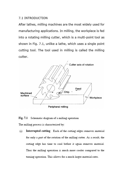
7.1 INTRODUCTIONAfter lathes, milling machines are the most widely used for manufacturing applications. In milling, the workpiece is fed into a rotating milling cutter, which is a multi-point tool as shown in Fig. 7.1, unlike a lathe, which uses a single point cutting tool. The tool used in milling is called the milling cutter.Fig. 7.1Schematic diagram of a milling operationThe milling process is characterised by:(i)Interrupted cutting Each of the cutting edges removes materialfor only a part of the rotation of the milling cutter. As a result, the cutting edge has time to cool before it again removes material.Thus the milling operation is much more cooler compared to the turning operation. This allows for a much larger material rates.(ii)Small size of chips Though the size of the chips is small, in view of the multiple cutting edges in contact a large amount of material is removed and as a result the component is generally completed ina single pass unlike the turning process which requires a largenumber of cuts for finishing.(iii)Variation in chip thickness This contributes to the non-steady state cyclic conditions of varying cutting forces during the contact of the cutting edge with the chip thickness varying from zero to maximum size or vice versa. This cyclic variation of the force can excite any of the natural frequencies of the machine tool system and is harmful to the tool life and surface finish generatedA milling machine is one of the most versatile machine tools. It is adaptable for quantity production as well as in job shops and tool rooms. The versatility of milling is because of the large variety of accessories and tools available with milling machines. The typical tolerance expected from the process is about ±0.050 mm.7.2 TYPES OF MILLING MACHINESTo satisfy various requirements milling machines come in a number of sizes and varieties. In view of the large material removal ratesmilling machines come with a very rigid spindle and large power. The varieties of milling machines available are:(i) Knee and Column type(a) horizontal(b) vertical(c) universal(d) turret typeThese are the general purpose milling machines, which have a high degree of flexibility and are employed for all types of works including batch manufacturing. A large variety of attachments to improve the flexibility are available for this class of milling machines.(ii) Production (Bed) type(a) simplex(b) duplex(c) triplexThese machines are generally meant for regular production involving large batch sizes. The flexibility is relatively less in these machines which is suitable for productivity enhancement.(iii) Plano millersThese machines are used only for very large workpieces involving table travels in meters.(iv) Special type(a) Rotary table(b) Drum type(c) Copy milling (Die sinking machines)(d) Key way milling machines(e) Spline shaft milling machinesThese machines provide special facilities to suit specific applications that are not catered to by the other classes of milling machines.7.2.1 Knee and Column Milling MachinesThe knee(升降台) and column type is the most commonly used machine in view of its flexibility and easier setup. A typical machine construction is shown in Fig. 7.2 for the horizontal axis. The knee houses the feed mechanism and mounts the saddle and table. The table basically has the T-slots running along the X-axis for the purpose of work holding. The table moves along the X-axis on the saddle while the saddle moves along the Y-axis on the guide ways provided on the knee.The feed is provided either manually with a hand wheel or connected for automatic by the lead screw, which in turn is coupled to the main spindle drive. The knee can move up and down (Z-axis) on a dovetail provided on the column.Fig. 7.2 Horizontal knee and column type milling machineThe massive column at the back of the machine houses all the power train including the motor and the spindle gearbox. The power for feeding the table lead screw is taken from the main motor through a separate feed gearbox. Sometimes a separate feed motor is provided for the feed gearbox as well.While the longitudinal and traverse motions are provided with automatic motion, the raising of the knee is generally made manually.The spindle is located at the top end of the column. The arbour used to mount the milling cutters is mounted in the spindle and is provided with a support on the other end to take care of the heavy cutting forces by means of an overarm with bearing. As shown in Fig.7.2 the overarm extends from the column with a rigid design. The spindle nose has the standard Morse taper of the suitable sizedepending upon the machine size.The milling cutters are mounted on the arbour at any desired position, the rest of the length being filled by standard hardened collars of varying widths to fix the position of the cutter. The arbour is clamped in the spindle with the help of a draw bar and then fixed with nuts.Milling machines are generally specified on the following basis:(i) Size of the table, which specifies the actual working area on the table and relates to the maximum size of the workpiece that can be accommodated.(ii) Amount of table travel, which gives the maximum axis movement that is possible.(iii) Horse power of the spindle, which actually specifies the power of the spindle motor used. Smaller machines may come with 1 to 3 hp while the production machines may go from 10 to 50 hp.Another type of knee and column milling machine is the vertical axis type. Its construction is very similar to the horizontal axis type, except for the spindle type and location.The vertical axis milling machine is relatively more flexible (Fig. 7.4) and suitable for machining complex cavities such as die cavities in tool rooms. The vertical head is provided with a swiveling facility in horizontal direction whereby the cutter axis can be swivelled. This isuseful for tool rooms where more complex milling operations are carried out.The spindle is located in the vertical direction and is suitable for using the shank mounted milling cutters such as end mills, In view of the location of the tool, the setting up of the workpiece and observing the machining operation is more convenient.Fig, 7.3 Vertical knee and column type milling machineFig.7.4 Some of the milling operations normally carried out on vertical axis machinesThe universal machine has the table which can be swivelled in a horizontal plane at about 45o to either the left or right. This makes the universal machine suitable for milling spur and helical gears as well as worm gears and cams.7.2.2 Bed Type Milling MachineIn production milling machines it is desirable to increase the metal removal rates. If it is done on conventional machines by increasingthe depth of cut, there is possibility of chatter. Hence another varietyof milling machines named as bed type machines are used which are made more rugged and are capable of removing more material. The ruggedness is obtained as a consequence of the reduction in versatility.The table in the case of bed type machines is directly mounted on the bed and is provided with only longitudinal motion.The spindle moves along with the column to provide the cutting action. Simplex machines (Fig. 7.5) are the ones with only one spindle head while duplex machines have two spindles (Fig. 7.6). The two spindles are located on either side of a heavy workpiece and remove material from both sides simultaneously.Fig. 7.5 Simplex bed type milling machineFig. 7.6 Duplex bed type milling machine7.3 MILLING CUTTERSThere are a large variety of milling cutters available to suit specific requirements. The versatility of the milling machine is contributed toa great extent by the variety of milling cutters that are available.7.3.1 Types of Milling CuttersMilling cutters are classified into various types based on a variety of methods.(i) Based on construction:(a) Solid(b) Inserted tooth typeBased on mounting:(a) Arbor mounted(b) Shank mounted(c) Nose mountedBase on rotation:(a) Right hand rotation (counter clockwise)(b) Left hand rotation (clockwise)Based on helix:(a) Right hand helix(b) Left hand helixMilling cutters are generally made of high speed steel or cemented carbides. The cemented carbide cutters can be of a brazed tip variety or with indexable tips. The indexable variety is more common since it is normally less expensive to replace the worn out cutting edges than to regrind them.Plain milling cutters These are also called slab milling cutters and are basically cylindrical with the cutting teeth on the periphery as shown in Fig. 7.7. These are generally used for machining flat surfaces.Fig. 7.7 Arbor mounted milling cutters for general purposeLight duty slab milling cutters generally have a face width, which is small of the order of 25 mm. They generally have straight teeth and large number of teeth.Heavy duty slab milling cutters come with a smaller number of teeth to allow for more chip space. This allows taking deeper cuts and consequently high material removal rates.Helical milling cutters have a very small number of teeth but a large helix angle. This type of cutter cuts with a shearing action, which can produce a very fine finish. The large helix angle allows the cutter to absorb most of the end load and therefore the cutter enters and leaves the workpiece very smoothly.Side and face milling cutters These have the cutting edges not only onthe face like the slab milling cutters, but also on both the sides. As aresult, these cutters become more versatile since they can be used for side milling as well as for slot milling.Staggered tooth side milling cutters are a variation where the teeth are arranged in an alternate helix pattern. This type is generally used for milling deep slots, since the staggering of teeth provides for greater chip space.Another variation of the side and face cutter is the half side milling cutter, which has cutting edges only on one side. This arrangement provides a positive rake angle and is useful for machining on only one side. These have a much smoother cutting action and a long tool life. The power consumed is also less for these cutters.Fig. 7.8Special forms of arbor mounted milling cuttersSlitting saws The other common form of milling cutters in the arbor mounted category is the slitting saw. This is very similar to a saw blade inappearance as well as function. Most of these have teeth around the circumference while some have side teeth as well. The thickness of these cutters is generally very small and is used for cutting off operations or for deep slots.Special form cutters In addition to the general type of milling cutters described above, there are a large number of special form milling cutters available which are used for machining specific profiles.Angular milling cutters are made in single or double angle cutters for milling any angle such as 30, 45 or 60o Form relieved cutters are made of various shapes such as circular, corner rounding, convex or concave shapes.T-slot milling cutters are used for milling T-slots such as those in the milling machine table. The central slot is to be milled first using an end mill before using the T-slot milling cutter. Woodruff key seat milling cutters are used for milling as the name suggests, woodruff key seats Some other special form cutters are dovetail milling cutters and gear milling cutters.End mills These are shank mounted as shown in Fig. 7.9 and are generally used in vertical axis milling machines. They are used for milling slots, key ways and pockets where other type of milling cutters cannot be used. A depth of cut of almost half the diameter can be taken with the end mills.The end mills have the cutting edge running through the length of the cutting portion as well as on the face radially up to a certain length. The helix angle of the cutting edge promotes smooth and efficient cutting even at high cutting speeds and feed rates. High cutting speeds(转速?) are generally recommended for this type of milling cutters.Fig. 7.9 Shank mounted milling cutters and various types of end mills There are a large variety of end mills. One of the distinctions is based on the method of holding, i.e., the end mill shank can be straight or tapered. The straight shank is used on end mills of small size and held in the milling machine spindle with the help of a suitable collet. The tapered shank can be directly mounted in the spindle with the help of the selfholding taper. If the taper is small compared to the spindle taper, then an adopter accommodating both the tapers is used.The end teeth of the end mills may be terminated at a distance from the cutter center or may proceed till the center (Fig. 7.9 f). Those with the cutting edge up to the center are called slot drills or end cutting end mills since they have the ability to cut into the solid material (Fig. 7.9 g). The other type of end mills which have a larger number of teeth cannot cut into solid material and hence require a pilot hole drilled before a pocket is machined.The cutting edge along the side of an end mill is generally straight and sometimes can be tapered by grinding on a tool and cutter grinder such that the draft required for mould and die cavities can be automatically generated.第七章铣削7.1介绍除了车床,铣床是制造应用中最广泛使用的。
高层建筑外文翻译 (2)

捆绑筒体结构——随着对高楼大厦不断的需求,框筒或桁架筒体结构逐渐被用于捆绑的形式,以创造更大的筒体结构,并保持其工作效率。在芝加哥10层的西尔斯总部大楼有九个筒体结构,在建筑的瓷砖基础捆绑三排。部分单独筒体建造到建筑的不同高度,展示了这一最新的建筑结构概念无限的可能性。西尔斯大厦有一千四百五英尺(442米)高,是世界上最高的建筑。
筒中筒结构——另一个在钢筋混凝土办公楼中结合了传统的外部框筒剪力墙施工的体系。该系统包括一个柱距紧密的外框架和内部剪力墙结构,将中央服务区包围起来。这种筒中筒结构,使得波士顿的目前全球最高(714英尺或218米)的轻质混凝土建筑的设计成为可能。
钢筋混凝土结构和钢结构的结合也得到了很好的发展,其中一个例子是Skidmore Owing和Merrill开发的混合结构,它是由外部的钢筋混凝土框架结构包围内部的钢结构所组成,从而结合了钢筋混凝土和钢结构的优点。新奥尔良52层的壳体广场大厦就是应用的这种结构。
Tall Buildings
Fazlur Rahrnan khan
Although there have been many advancements in building construction technology in general, spectacular achievements have been made in the design and construction of ultrahigh-rise buildings.
通货膨胀会计外文资料翻译 (2)

毕业设计(论文)外文资料翻译题目:Inflation Accounting附件: 1.外文资料翻译译文;2.外文原文。
附件1:外文资料翻译译文通货膨胀会计自从我们开始认识我们周遭的事物, 我们常常从我们的祖父母那里听到关于他们那个时代的东西,尤其是黄金和酥油是非常便宜的.那时我们常常想为什么他们的那个时代的东西非常便宜,而我们的这个时代的东西开始变得昂贵. 因此, 这个问题使我们感到困惑.但是现在, 随着我们的知识的增加和认识, 我们已经知道了通货膨胀这中现象, 用一种外行的理解是国家定价的增长或货币的贬值是已知背后的最大的原因.现在出现的问题究竟是不是通货膨胀?在当今世界, 通货膨胀是一个全球性的现象. 在资本主义世界的今天,几乎没有任何国家不受通货膨胀幽灵般的困扰.不同的经济学家用不同的词语定义通货膨胀, Prof.Crowther 定义的通货膨胀是“随着国家币值的下降, 或者是价格的上涨.” Prof.Paul Einzig 说“通货膨胀是一个不平衡的状态,总体表现是购买力扩张的原因或者是价格水平增长的影响.”两个定义都强调了物价上涨.通货膨胀的最基本的因素不是需求的增加就是供应的减少.通货膨胀对企业的影响通货膨胀对企业的影响可以分为两部分理解1.影响成本和收益2.影响资产和负债至于通货膨胀对成本和收益的影响是忧虑的, 肯定的, 两者都将上升. 但是他们的结果是否表现出超常的利润是被公司旧的价格的可用的期初存货的多少和被公司受理的工资的需求的多少决定的.在货币资产和负债中, 一个公司将失去被债权人和取得在真实项目中的被债务人.如果我们说其他的资产如建筑物, 土地和其他证券, 则公司将在货币方面有持有收益,但是在实质情况中还是有一定的影响, 因此,在价格方面的增长是一方面, 货币币值的下降是另一方面.通货膨胀会计及其意义通货膨胀影响产出和资产价格上涨的形式. 因为财务会计通常是以历史成本为记帐原则, 因此他们不考虑资产和产出价格上涨的影响. 这样的结果很可能会导致利润上的虚增, 资产价格的低估以及误导企业的决策.因此, 在以历史成本为记帐原则编制的财务报表通常被证明是历史事实的一种陈述, 并不能反映企业当前的商业价值. 这就剥夺了如管理者, 股东以及债权人等的报表使用者去获取正确的财务信息从而做出正确的经营决策的权力.因此,这就导致了对通货膨胀会计的需要. 通货膨胀会计是一个会计制度范围的术语描述, 设计并去纠正当通货膨胀存在时历史成本会计产生的上升的问题.通货膨胀会计的意义是从固有的历史成本会计制度的限制中产生的.以下是历史成本会计的局限性:1.历史成本会计不考虑, 因受通货膨胀影响, 从资产的货币价值上升产生的未实现的持有性收益.2.折旧费用的目标是在资产的使用寿命期间摊销其成本, 并在将来为其更换储备. 但是, 他并没有考虑到受通货膨胀影响的结果可能导致折旧费用不足的替换成本.3.根据历史成本会计, 以旧的价格获得的存货实现的收益是按当年的价格计算的. 在通货膨胀期间, 由于持有收益和经营收益的最大化, 可能导致利润上的虚增.4.从历史收益上,不容易去预测未来盈利.通货膨胀会计的历史在过去的几年中, 通货膨胀会计已经被作为一种补充运用在英国和美国的财务报表中, 关于在通货膨胀期间调整财务账目的方法已经争论了50多年的时间.早在1900年代初, 美国和英国的会计师就以经讨论过通货膨胀对财务报表的影响, 开始于指标的数据理论和购买力. Irving Fisher 在1911年出版的书《The Purchasing Power of Money》被Henry W.Sweeney 在1936年出版的关于恒定购买力会计的书中《Stabilized Accounting》作为起源. Sweeney的这一模型通过美国注册会计师协会为他们的研究性学习(ARS6)报告《the Financial Effects of Price-Level Changes》所应用, 后来又被应用到会计准则委员会(美国), 金融标准委员会(美国),会计标准指导委员会(英国). Sweeney主张用涵盖在国民生产总值之上的价格指标.在1979年3月,美国财务会计准则委员会(FASB)写了恒定美元会计, 当中主张使用消费价格指数为所有的城市消费者(CPI-U)去调整帐目, 因为其可在每月计算一次.在大萧条期间, 一些公司重述他们的财务报表, 以反映通货膨胀. 在过去50年的时间里, 标准制定组织应经鼓励企业用价格水平调整的方法去补充以成本为基础的财务报表. 在20世纪70年代的高通货膨胀时期, 当美国证券交易委员会(SEC)发行ASR190时, 财务会计准则委员会(FASB)正在审查关于价格水平调整报表的草案, 这需要美国大约1000家最大的公司提供基于替换成本的补充信息. 财务会计准则委员会撤回了草案.然而为了迎合通货膨胀会计的需要, 国际会计准则委员会(IASB)推出了世界闻名的会计准则IAS29.通货膨胀会计的方法为了衡量通货膨胀对财务报表的影响,使用的技术如下:当前购买力法(CPP)根据这一价格变动调整帐目的方法, 在财务报表中所有的项目都被重述在一个固定的货币单位的项目里, 也即一般购买力.为了衡量价格水平的变化, 并用一般物价指数把这一变化纳入到财务报表当中去, 这就意味着我们的目标很可能是一个晴雨表. 该指数被用于转换在资产负债表和利润表中各个项目的价值. 这个方法考虑了账户一般货币购买力的变化以及忽略了给定项目价格的实际上升或下降. 在当前的购买力下, 购买力法(CPP)涉及了历史数据的翻新.为了这一目标, 在这一时期的最后时刻, 历史数据被转换成了购买力的价格. 被要求的两个指标数据: 一个显示在期末的一般价格水平上, 另一个反映相同的数据在交易日.这种方法下的利润一段时间内在净资产价值方面上是增长的, 在当前购买力的项目中所有的价格是被估计出来的.现行成本会计(CCA)的方法现行成本会计是对当前购买力法的替代方法. 现行成本会计方法相当于在盈利中现行的收益与被消耗资源的现行成本.一般物价水平的变动通过指标数据去衡量. 具体价格发生变化, 如没有任何价格变动的特定资产的价格发生变化. 可以根据这一方法去解决, 资产按照当前的成本估价, 即资产被替换时的成本.通货膨胀会计的局限性虽然通货膨胀会计是一种更实际的做法,并能反映公司真实地财务情况, 但是有些限制不允许它成为一个普及的会计系统. 以下是他的限制:1.价格水平的变化是一个持续的过程.2.这个系统使计算变得乏味, 因为有太多的转换和计算.3.该系统没有被税务机关给予优惠.结论:在地球上的每一个人都受到通货膨胀的影响, 一些人表现出积极,但是大部分人表现的消极, 因为通货膨胀导致了一般购买力的侵蚀.历史成本会计没有考虑帐户中资产价值的变化, 由于通货膨胀影响的资产负债表和利润表, 不能真实的反映企业的价值及所需要的有效的决策信息.通货膨胀会计已经剔除了这个缺陷, 通过根据一般或具体价格水平的方法去调整数据.尽管对财务报表提出了正确的方法, 但是通货膨胀会计由于某些限制仍然没有得到广泛的普及. 但是随着在这一领域更多的研究和会计软件的开发, 毫无疑问, 调整后的通货膨胀会计就是财务会计的未来.附件2:外文原文Inflation Accounting/Faculty_Column/FC1103/fc1103.htmlSince we started understanding things around us, we all used to listen from our Grandparents about the things and articles especially Gold & Ghee being cheaper in their times.That time we used to think that why the things were cheaper in our Grandparent’ time and why had they started becoming costlier. So this question would keep us puzzled.But now as we have grown in our knowledge and understanding, we have come to know about the phenomenon of Inflation which in layman’s language is known as the state of rising pricing or the falling value of maney was the greatest reason behind this.Now emerges the question that what exactly is the Inflation?Inflation is a global phenomenon in present day times. There is hardly any country in the capitalist world today which is not afficted by spectre of inflation.Different economists have defined inflation in different words like Prof.Crowther has defined inflation “as a state in which the value of money is falling, ie, prices are tising.” In the words of Prof.Paul Einzig, “Inflation is that state of disequilibrium in which an expansion of purchasing power tend s to cause or is the effect of an increase of price level.” Both the definition have emphasized on the rising prices of the goods.The basic factors behind the inflation are either the rising demand or the shortening of supply due to any reason.Effect of Inflation on BusinessThe impact of inflation on business can be bifurcated into two parts like1.Impact on costs and revenue2.Impact on assets and liabilitiesAs far as impact of inflation on costs and revenues is concerned, definitely both will rise but whether they result into extraordinary profits will be determined by that how much opening stock was available at old prices with the company and how much later the demand for increasing wages is entertained by the company.In case of monetary assets and liabilities, accompany will lose of being creditor and gain in case of being debtor in real terms.If we talk about other assets like building, land and other securities, the company will be having holding gains in monetary terms but may have neutral impact in real terms due to the rise in prices on the one hand but fall in value of money on the other.Inflation Accounting and its significanceThe impact of inflation comes in the form of rising prices of output and assets. As the financial accounts are kept on Historical cost basis, so they don’t take into consideration the impact of rise in the prices of assets and output. This may sometimes result into the overstated profits, under priced assets and misleading picture of Business etc.So, the financial statements prepared under historical accounting are generally proved to be statements of historical facts and do not reflect the current worth of business. This deprives the users of accounts like management, shareholders, and creditors etc. to have a right picture of business to make appropriate decisions.Hence, this leads towards the need for Inflation Accounting. Inflation accounting is a term describing a range of accounting systems designed to correct problems arising from historical cost accounting in the presence of inflation.The significance of inflation accounting emerges from the inherent limitations of the historical cost accounting system.Following are the limitations of historical accounting:1.Historical accounts do not consider the unrealized holding gains arising from the rise in themonetary value of the assets due to inflation.2.The objective of charging depreciation is to spread the cost of the asset over its useful life andmake reserve for its replacement in the future. But it does not take into account the impact of inflation over the replacement cost which may result into the inadequate charge of depreciation.3.Under historical accounting, inventories acquired at old prices are marched against revenuesexpressed at current prices. In the period of inflation, this may lead to the overstatement of profits due mixing up of holding gains and operating gains.4.Future earnings are not easily projected from historical earnings.History of Inflation AccountingIn the last few years, inflation accounting has been adopted as a supplementary financial statement in the United States and the United Kingdom. This comes after more than 50 years of debate about methods of adjusting financial accounts for inflation.Accountants in the United Kingdom and the United States have discussed the effect of inflation on financial statements since the early 1900s, beginning with index number theory and purchasing power. Irving Fisher’s 1911 book the Purchasing Power Accounting. This model by Sweeney was used by The American Institute of Certified Public Accountants for their 1936 research study(ARS6) Reporting the Financial Effects of Price-Level Changes, and later used by the Accounting Principles Board (USA), The Financial Standards Board (USA), and the Accounting Standards Steering Committee (UK). Sweeney advocated using a price index that covers everything in the gross national product. In March 1979, the Financial Accounting Standards Board (FASB) wrote Constant Dollar Accounting, which advocated using the Consumer Price Index for Al Urban Consumers (CPI-U) to adjust accounts because it is calculate every month.During the Great Depression, some corporations restated their financial statements to reflect inflation. At times during the past 50 years standard-setting organizations have encouraged companies to supplement cost-based financial statements with price-level adjusted statements. During a period of high inflation in the 1970s, the FASB was reviewing a draft proposal for price-level adjusted statements when the Securities and Exchange Commission (SEC) issued ASR 190, which required approximately 1,000 of the largest US corporations to provide supplemental information based on replacement cost. The FASB withdrew the draft proposal.Still to cater to the needs of an Inflation Accounting, the IASB came out with Accounting Standard known as IAS29.Techniques of Inflation AccountingTo measure the impact of inflation on financial statements, following are the techniques used: Current Purchasing Power (CPP) MethodUnder this method of adjusting accounts to price changes, all items in the financial statements are restated in terms of a constant unit of money ie in terms of general purchasing power. For measuring changes in the price level and incorporating the changes in the financial statements we use General Price Index, which may be considered to be a barometer meant for the purpose. The index is used to convert the values of various items in the Balance Sheet and Profit and Loss Account. This method takes into account the changes in the general purchasing power of money and ignores the actual rise or fall in the price of the given item. CPP method involves the refurnishing of historical figures at current purchasing power. For this purpose, historical figures are converted into value of purchasing power at the end of the period. Two index numbers are required: one showing the general price level at the end of the period and the other reflecting the same at the date of the transaction.Profit under this method is an increase in the value of the net asset over a period, all valuations being made in terms of current purchasing power.Current Cost Accounting (CCA) MethodThe Current Cost Accounting is an alternative to the Current Purchasing Power Method. The CCA method matches current revenues with the current cost of the resources which are consumed in earning them.Changes in the general price level are measured by Index Numbers. Specific price change occurs if price of a particular asset change without any general price change. Under this method, asset are valued at current cost which is the cost at which asset can be replaced as on a date.While the Current Purchasing Power (CPP) method is known as the General Price Level approach, the Current Cost Accounting (CCA) method is known as Specific Price Level approach or Replacement Cost Accounting.Limitations of Inflation AccountingThough Inflation Accounting is more practical approach for the true reflection of financial status of the company, there are certain limitations which are not allowing this to be a popular system of accounting. Following are the limitations:1.Change in the price level is a continuous process.2.This system makes the calculations a tedious task because of too many conversions andcalculations.3.This system has not been given preference by tax authorities.ConclusionEvery person on this earth has been affected by Inflation, some positively but most of the people negatively because the Inflation leads to the erosion of general purchasing power. The Inflation spares none and it equally influences the Businesses like the people.Historical cost accounting does not take into account the change in the rise in the value of assets and its impact on Balance Sheet and P&L Account due to inflation and does not reflect the real worth of the business which is very required for effective decision making.Inflation Accounting has removed this drawback by providing methods for adjusting the figure accounting to General or Specific Price levels.Despite a right method of presenting financial statements, Inflation Accounting is still not widely prevalent due to certain limitations. But with more research and development of accounting software in this field, there is no doubt that Inflation adjusted accounting is the future of Financial Accounting.。
建筑外文翻译2

多层住宅楼结构设计的故事引言设计和建造在塞勒姆,泰米尔纳德邦州,印度是本文描述。
设计是交由证明第二次检查的作者。
该建筑是一幢公寓的泰米尔纳德邦房屋委员会给的建议。
这是一个钢筋混凝土框架建设。
这样做是在技术,哥印拜陀,印度,巴黎圣日尔曼学院作为高级论文设计的世平的一部分,在马萨诸塞州伍斯特,01609巴黎圣日耳曼技术,哥印拜陀,印度,学院在印度项目中心的7周内学生作为一个住宅项目。
学生姓名弗雷德里克嘉莉,亚伯拉罕松柏目和安东尼。
这是他们完成在巴黎圣日尔曼学院项目的技术,哥印拜陀,印度,中心在1998年。
这是对BSCE在土木与环境工程学士学位世平要求的一部分。
世平派出20名学生到印度计划在PSG技术学校,哥印拜陀,学院计划在美国拉惹博士,主席,中欧和东欧处圣日耳曼技术学院赞助。
拉惹古玛教授担任顾问的校园,而体育Jayachandran教授,担任过外的世平校园顾问。
学生们做了文献调查,问题的定义,没有一个完整的结构分析和4层住宅大楼在设计钢筋混凝土。
他们遵循国际清算银行在印度的代码456 - 1978和使用脑梗死- 1999和风能/加拿大代码使用1995年的地震荷载和ANSI标准检查1995。
分析和设计的地砖,梁,梁,柱和基脚已完成利用钢筋混凝土结构设计与分析理论,STAAD 进行第三软件,它使用有限元。
对板设计,梁,柱和基脚外出使用该软件进行钢筋混凝土设计套件。
图纸完成使用自动加元。
为了防止这些软件被滥用,极限状态设计是专门用来作为手工计算方法来验证从STAAD进行输出,三和RC设计套件。
估计和工料测量做是为了计算数量和建筑和制造规范移仍维持在H/500,在理论设计的改编,由 C.K. Wang和 C.G. Salmon的教科书钢筋混凝土设计和JGMcGrager,钢筋混凝土设计和S.Rajasekaran,有限元方法。
学生已完成结构设计和图纸和技术报告,并提出了结果的陈述,之前的资深教授和其他教师和大学生的心理服务技术的观众,以及在世平。
PLC外文翻译 (2)

外文资料翻译Everyone knows there's only one constant in the technology world, and that's change. This is especially evident in the evolution of Programmable Logic Controllers (PLC) and their varied applications. From their introduction more than 30 years ago, PLCs have become the cornerstone of hundreds of thousands of control systems in a wide range of industries.At heart, the PLC is an industrialized computer programmed with highly specialized languages, and it continues to benefit from technological advances in the computer and information technology worlds. The most prominent of which is miniaturization and communications.The Shrinking PLCWhen the PLC was first introduced, its size was a major improvement - relative to the hundreds of hard-wired relays and timers it replaced. A typical unit housing a CPU and I/O was roughly the size of a 19 television set. Through the 1980s and early 1990s, modular PLCs continued to shrink in footprint while increasing in capabilities and performance (see Diagram 1 for typical modular PLC configuration).In recent years, smaller PLCs have been introduced in the nano and micro classes that offer features previously found only in larger PLCs. This has made specifying a larger PLC just for additional features or performance, and not increased I/O count, unnecessary, as even those in the nano class are capable of Ethernet communication, motion control, on-board PID with autotune, remote connectivity and more.PLCs are also now well-equipped to replace stand-alone process controllers in many applications, due to their ability to perform functions of motion control, data acquisition, RTU (remote telemetry unit) and even some integrated HMI (human machine interface) functions. Previously, thesefunctions often required their own purpose-built controllers and software, plus a separate PLC for the discrete control and interlocking.The Great CommunicatorPossibly the most significant change in recent years lies in the communications arena. In the 1970s Modicon introduction of Modbus communications protocol allowed PLCs to communicate over standard cabling. This translates to an ability to place PLCs in closer proximity to real world devices and communicate back to other system controls in a main panel.In the past 30 years we have seen literally hundreds of proprietary and standard protocols developed, each with their own unique advantages.Today's PLCs have to be data compilers and information gateways. They have to interface with bar code scanners and printers, as well as temperature and analog sensors. They need multiple protocol support to be able to connect with other devices in the process. And furthermore, they need all these capabilities while remaining cost-effective and simple to program.Another primary development that has literally revolutionized the way PLCs are programmed, communicate with each other and interface with PCs for HMI, SCADA or DCS applications, came from the computing world.Use of Ethernet communications on the plant floor has doubled in the past five years. While serial communications remain popular and reliable, Ethernet is fast becoming the communications media of choice with advantages that simply can't be ignored, such as: * Network speed. * Ease of use when it comes to the setup and wiring. * Availability of off-the-shelf networking components. * Built-in communications setups.Integrated Motion ControlAnother responsibility the PLC has been tasked with is motion control. From simple open-loop to multi-axis applications, the trend has been to integrate this feature into PLC hardware and software.There are many applications that require accurate control at a fast pace, but not exact precision at blazing speeds. These are applications where the stand-alone PLC works well. Many nano and micro PLCs are available with high-speed counting capabilities and high-frequency pulse outputs built into the controller, making them a viable solution for open-loop control.The one caveat is that the controller does not know the position of the output device during the control sequence. On the other hand, its main advantage is cost. Even simple motion control had previously required an expensive option module, and at times was restricted to more sophisticated control platforms in order to meet system requirements.More sophisticated motion applications require higher-precision positioning hardware and software, and many PLCs offer high-speed option modules that interface with servo drives. Most drives today can accept traditional commands from host (PLC or PC) controls, or provide their own internal motion control. The trend here is to integrate the motion control configuration into the logic controller programming software package.Programming LanguagesA facet of the PLC that reflects both the past and the future is programming language. The IEC 61131-3 standard deals with programming languages and defines two graphical and two textual PLC programming language standards: * Ladder logic (graphical). * Function block diagram (graphical). * Structured text (textual).Instruction list (textual).This standard also defines graphical and textual sequential function chart elements to organize programs for sequential and parallel control processing.Based on the standard, many manufacturers offer at least two of these languages as options for programming their PLCs. Ironically, approximately 96 percent of PLC users recently still use ladder diagrams to construct their PLC code. It seems that ladder logic continues to be a top choice given it's performed so well for so long.Hardware PlatformsThe modern PLC has incorporated many types of Commercial off the Shelf (COTS) technology in its CPU. This latest technology gives the PLC a faster, more powerful processor with more memory at less cost. These advances have also allowed the PLC to expand its portfolio and take on new tasks like communications, data manipulation and high-speed motion without giving up the rugged and reliable performance expected from industrial control equipment.New technology has also created a category of controllers called Programmable Automation Controllers, or PACs. PACs differ from traditional PLCs in that they typically utilize open, modular architectures for both hardware and software, using de facto standards for network interfaces, languages and protocols. They could be viewed as a PC in an industrialPLC-like package.Overall, PLC users are satisfied with the products currently available, while keeping their eye on new trends and implementing them where the benefits are obvious. Typically, new installations take advantage of advancing technologies, helping them become more accepted in the industrial world.众所周知,科技世界里只有一个永恒真理,那就是变化。
工业设计_外文翻译-2

Design and Environment/baidu?word=%B9%A4%D2%B5%C9%E8%BC%C6%D3%A2%CE%C4%CE%C4%CF%D 7&tn=sogouie_1_dg原文:DESIGN and ENVIRONMENTProduct design is the principal part and kernel of industrial design. Product design gives uses pleasure. A good design can bring hope and create new lifestyle to human.In spscificity,products are only outcomes of factory such as mechanical and electrical products,costume and so on.In generality,anything,whatever it is tangibile or intangible,that can be provided for a market,can be weighed with value by customers, and can satisfy a need or desire,can be entiled as products.Innovative design has come into human life. It makes product looking brand-new and brings new aesthetic feeling and attraction that are different from traditional products. Enterprose tend to renovate idea of product design because of change of consumer's lifestyle , emphasis on individuation and self-expression,market competition and requirement of individuation of product.Product design includes factors of society ,economy, techology and leterae humaniores.Tasks of product design includes styling, color, face processing and selection of material and optimization of human-machine interface.Design is a kind of thinking of lifestyle.Product and design conception can guide human lifestyle . In reverse , lifestyle also manipulates orientation and development of product from thinking layer.With the development of science and technology ,more and more attention is paid to austerity of environmental promblems ,such as polluting of atmosphere,destroy of forest, soilerosion,land desertification, water resource polluting, a great deal of species becaming extinct,exhansting of petroleum , natural gas andcoal and so on . A designer should have a strong consciousness of protecting environment and to make his\her design to be based on avoiding destroying environment and saving natural recourse.Nowadays ,greenhouse effects,destroyed ozone layers and acid rain are three global environmental questions.Greenhouse effect is phenomena of the atmosphere becoming warmer . The forming principle of greenhouse effect is that the Sun short wave radiation can penetrate into ground through atmosphere ,long wave radiation emitted from ground after ground is warmed ,is absorbed by carbon dioxide of atmosphere , and then atmosphere gets warmer.The carbon dioxide in the atmosphere changes the earth to a large greenhouse like a thick layer of glass . Methane ,ozone,chlorine,Fluorine, hydrocarbon and aqueous vapor also make some contribution to greenhouse effects. With rapid increase of population and rapid development of industry ,more and more carbon dioxide of atmosphere enters into atmosphere. Because forest is cun down in a large amount also ,carbon dioxide increases gradally ,and the greenhouse effects are strengthened constantly .The results of the greenhouse effects are very serious. The great changes will take place in the natural ecology ,such as desert expanding ,land corroding aggravating, forest retreating to the polarregion, calamity of drought and waterlog serious and rainfall increasing. The temperate zone will be wetter in water and will be droughtier in summer . Tropical zone will become wetter and subtropical zone will become more arid . All of these above will forces the existing irrigation works to be adjusted. Coastal regions will be threatened seriously .Because the temperature is rising , ice-cubes will be melted at the two poles so to the sea level will be rising and a lot of cities and ports will be submerged.The ozone layer destroyed shocked academia and the whole international aommunity .American scientists,Monila and Rowland , pointed out that it is human activities bring ozone hole of today . arch-criminal that we now well know is freon and Kazakhstan dragon.Acid rain has already become a kind of air pollution phenomenon in extensive range,crossing over national boundaries at present. Acid rain destroys soil, makes lakeacid and endangers growing of abimals and plants. It also stimulates people's skin, brings out the skin disease, causes lung hydronces, lung harden ,and corrodes the metal product,paint ,leather, fabrics and building with carbonate .In a word , the environment of human life has already worsened day by day. The reasons of the worsening mostly come from the human own bad life style, disrespecting the objective law, eager for quick success,use of the earth resource without scientific plan ,and lack of consciousness pratecting the environment in design . So they destroy home by themselves,which not only harm human on contemporary, but also seriously influence existence of descendants.The environmental question is caused by people's bad design and life style to a great extent , which puts forward a serious question for a designer that designers should undertake the historical important task of environment protection.Industry has brought the disaster to world while creates a large amount of wealth for mankind . Industry design has accelerated the consumpition of the resource and energy resource and has caused enormous destruction to the ecological balance of the earth while creating modern life style and living environment for mankind.So as industry designers, setting up environmental awareness incarnates their morals and social sense of responsibility. Designers must be responsible for their own designs, and must take human health and blessedness , and harmonically coexisting of nature with the human as the rules necessarily obeyed in their own design.Designers must also master the necessary knowledege in material, craft, chemical industry, manufacturing,ect.,in order to be possible for avoiding to danger to environment causing by his design.The concept of "Sustainable development design"has epoch-maling meanings of humanity and real development of the world .It reflects the designer's morals and responsibility , and has already become the trend of designing development in the 21st century .Hence ,mankind's development made of traditional industrial civilization was turned to one of the modern ecological civilization. It is the coordination of social progress,economic growth and environmental protestion.Sustainable development is a kind concept of brand-new ethics,morals andvalues that people should follow. Its essence lies in fully utilizing the modern science and technongy ,exploiting green resources ,development constantly, impelling harmonious development between human and nature and pramoting inter-harmony of population ,resource and environment .Solving the problem of sustainable development is a change of technological innovation and behavior made.Sustainable development strategy is to solve the problem of meeting contemporary people's demands in maximum under the precondition of un-hurting several generations' demands of the future . It will realize the unity of the present interests and long-term interest and leave the development space for descendants.The question of the strategic consideration of sustainable development should include circulation, green energy and ecological efficiency.Green design comes from introspection on environmental and ecological disruption caused by design of modern technology and culture. Green design focuses on the balance relation of persons and natural ecology . Designers should consider the environmental benefits at every decision of the disign process, and try their best to reduce the destruction to environment.For industry design, the core of green design is "3R",namely Reduce,Recycle and Reuse.It is necessary not only to reduce consunption of substance and energy sources,and reduce letting of harmful substance,but also to classified reclaim, recycle and reuse products and parts conveniently.Green design is not only technical ,but also an innovative idea. It requires designer to give up some rat-fuck method excessively emphasizing at the style of products, and to focus on the real innovative. He or she would design the form of the products with more responsible method and make the products lengthen their wervice life as much as possible through succinct and permanent modeling.For materials,stock and regeneration of raw materials, consumption and pollution of environmental energy during obtaining materials,machining performance in follow-up manufacturing,low consumption and low pollution of energy ,and reclaimable during discarded should be considered.Problems of manufacturing are that pollution should be reduced or died out during beginning of manufacturing.Consideration on packing, transporting , sale, ect. is meant the environmental performance of packaging, green packing ,good performance of transportation ,decreasing self weight , reducing energy consumption , localized production and reducing consimption of work flow.Consideration on the use of product concerns with waste of energy and resources while produces are used , the modularization of environmental performance , recombined ability , and the mades of using product while products are renewed , as well as other factors.Easy disassembled feature , convenient decomposition and classification , reclaaimable and reusable features of materials, and recombined feature of parts or removes for other use should all be considered during the period while products are renewed , as well as other factors.Easy disassembled feature, convenient decomposition and classification , reclaimable and reusable features of materials, and recombined feature of parts or removed for other use should all be considered during the period while products are discarded .Clean energy souces should be Considered , such as solar ernergy , water, electricity and wind power .Clean materials concern with low pollution , innocuity, disaggregation and reclaimable . Clean manufacturing process is meant production with energy saving and environment protection while used, and reclaimable while discarded.Regeneration and reuse of parts are powerful measure of sustainable strategy. The fact has proved that through disassembly and analysis the proportion of reusable material would be higher after improving design and retread.For example , in a scrap car , metal meterial accounts for 80%.Among them , nonferrous metal accounts for 3%~4.7%. 45%of output of steel comes from scrap steeel in world and 25% output of steel comes from scrap steel in our country.Product Lifecycle Management is meant all life course of product from people'sdemand for product to be washed out , including the main stages of demand analysis, praduct planning , conceptual design , produce design , digitized simulation, proceess preparation , process planning,production testing and quaality control , sell and distribution, use \maintaining and maintain, as well as scrap and reclaiming . Advanced management idea and first-class information technology are taken into industrial and commercial operation in modern enterprises , which makes enterprises be able to adjust management means and management ways effectively in digital economic era , inoder to exert enterprise's unprecedented competition advantage . Helping enterprise to carry on products innovation , to win the market , and to obtain additional profit would improve the value of the enterprise products.译文:设计与环境产品设计是工业设计的主体和核心。
变压器外文翻译 (2)
英文资料TRANSFORMER1. INTRODUCTIONThe high-voltage transmission was need for the case electrical power is to be provided at considerable distance from a generating station. At some point this high voltage must be reduced, because ultimately is must supply a load. The transformer makes it possible for various parts of a power system to operate at different voltage levels. In this paper we discuss power transformer principles and applications.2. TOW-WINDING TRANSFORMERSA transformer in its simplest form consists of two stationary coils coupled by a mutual magnetic flux. The coils are said to be mutually coupled because they link a common flux.In power applications, laminated steel core transformers (to which this paper is restricted) are used. Transformers are efficient because the rotational losses normally associated with rotating machine are absent, so relatively little power is lost when transforming power from one voltage level to another. Typical efficiencies are in the range 92 to 99%, the higher values applying to the larger power transformers.The current flowing in the coil connected to the ac source is called the primary winding or simply the primary. It sets up the flux φ in the core, which varies periodically both in magnitude and direction. The flux links the second coil, called the secondary winding or simply secondary. The flux is changing; therefore, it induces a voltage in the secondary by electromagnetic induction in accordance with Lenz’s law. Thus the primary receives its power from the source while the secondary supplies this power to the load. This action is known as transformer action.3. TRANSFORMER PRINCIPLESWhen a sinusoidal voltage V p is applied to the primary with the secondary open-circuited, there will be no energy transfer. Th e impressed voltage causes a small current Iθ to flow in the primary winding. This no-load current has two functions: (1) it produces the magnetic flux in the core, which varies sinusoidally between zero and φm, where φm is the maximum value o f the core flux; and (2) it provides a component to account for the hysteresis and eddy current losses in the core. There combined losses are normally referred to as the core losses.The no-load current Iθ is usually few percent of the rated full-load current of the transformer (about 2 to 5%). Since at no-load the primary winding acts as a large reactance due to the iron core, the no-load current will lag the primary voltage by nearly 90º. It is readily seen that the current component Im= I0sinθ0, called t he magnetizing current, is 90º in phase behind the primary voltage V P. It is this component that sets up the flux in the core; φ is therefore in phase with Im.The second component, Ie=I0sinθ0, is in phase with the primary voltage. It is the current compon ent that supplies the core losses. The phasor sum of these two components represents the no-load current, orI0 = I m+ I eIt should be noted that the no-load current is distortes and nonsinusoidal. This is the result of the nonlinear behavior of the core material. If it is assumed that there are no other losses in the transformer, the induced voltage In the primary, E p and that in the secondary, Es can be shown. Since the magnetic flux set up by the primarywinding ,there will be an induced EMF E in the secon dary winding in accordance with Faraday’s law, namely, E=NΔφ/Δt. This same flux also links the primary itself, inducing in it an EMF, Ep. As discussed earlier, the induced voltage must lag the flux by 90º, therefore, they are 180º out of phase with the applied voltage. Since no current flows in the secondary winding, Es=Vs. The no-load primary current I0 is small, a few percent of full-load current. Thus the voltage in the primary is small and Vp is nearly equal to Ep. The primary voltage and the resulting flux are sinusoidal; thus the induced quantities Ep and Es vary as a sine function. The average value of the induced voltage given by Eavg = turns×given timegiven time a in flux in change which is Faraday’s law applied to a finite time interval. It follows thatm m 4fN 1/(2f)2N Eavg ϕϕ== which N is the number of turns on the winding. Form ac circuit theory, the effective or root-mean-square (rms)voltage for a sine wave is 1.11 times the average voltage; thusm 4.44fN E ϕ=Since the same flux links with the primary and secondary windings, the voltage per turn in each winding is the same. Hencem P P 4.44fN E ϕ=andm S S 4.44fN E ϕ=where E p and Es are the number of turn on the primary and secondary windings, respectively. The ratio of primary to secondary induced voltage is called the transformation ratio. Denoting this ratio by a, it is seen thatS P S P N N E E a ==Assume that the output power of a transformer equals its input power, not a bad sumption in practice considering the high efficiencies. What we really are saying is that we are dealing with an ideal transformer; that is, it has no losses. ThusP m = P outorV p I p × primary PF = V s I s × secondary PFwhere PF is the power factor. For the above-stated assumption it means that the power factor on primary and secondary sides are equal; thereforeV p I p = V s I sfrom which is obtainedS P S P I I V V =≌S P E E ≌aIt shows that as an approximation the terminal voltage ratio equals the turns ratio. The primary and secondary current, on the other hand, are inversely related to the turns ratio. The turns ratio gives a measure of how much the secondary voltage is raised or lowered in relation to the primary voltage. To calculate the voltage regulation, we need more information.The ratio of the terminal voltage varies somewhat depending on the load and its power factor. In practice, the transformation ratio is obtained from the nameplate data, which list the primary and secondary voltage under full-load condition.When the secondary voltage Vs is reduced compared to the primary voltage, the transformation is said to be a step-down transformer: conversely, if this voltage is raised, it is called a step-up transformer. In a step-down transformer the transformation ratio a is greater than unity (a>1.0), while for a step-up transformer it is smaller than unity (a<1.0). In the event that a=1, the transformer secondary voltage equals the primary voltage. This is a special type of transformer used in instances where electrical isolation is required between the primary and secondary circuit while maintaining the same voltage level. Therefore, this transformer is generally knows as an isolation transformer.As is apparent, it is the magnetic flux in the core that forms the connecting link between primary and secondary circuit. In section 4 it is shown how the primary winding current adjusts itself to the secondary load current when the transformer supplies a load.Looking into the transformer terminals from the source, an impedance is seen which by definition equals Vp / Ip. From S P S P I I V V =≌S P E E ≌a, we have Vp = aVs and Ip = Is/a.In terms of Vs and Is the ratio of Vp to Ip isss 2S S P P I V a /a I aV I V ==But Vs / Is is the load impedance Z L thus we can say thatZ m (primary) = a 2Z L This equation tells us that when an impedance is connected to the secondary side, it appears from the source as an impedance having a magnitude that is a 2 times its actual value. We say that the load impedance is reflected or referred to the primary. It is this property of transformers that is used in impedance-matching applications.4. TRANSFORMERS UNDER LOADThe primary and secondary voltages shown have similar polarities, as indicated by the “dot-making ” convention. The dots near the upper ends of the windings have the same meaning as in circuit theory; the marked terminals have the same polarity. Thus when a load is connected to the secondary, the instantaneous load current is in the direction shown. In other words, the polarity markings signify that when positive current enters both windings at the marked terminals, the MMFs of the two windings add.In general, it will be found that the transformer reacts almost instantaneously to keep the resultant core flux essentially constant. Moreover, the core flux φ0 drops very slightly between n o load and full load (about 1 to 3%), a necessary condition if Ep is to fall sufficiently to allow an increase in Ip.On the primary side, Ip’ is the current that flows in the primary to balance the demagnetizing effect of Is. Its MMF N p I p’ sets up a flux linking the primary only. Since the core flux φ0 remains constant. I0 must be the same current that energizes the transformer at no load. The primary current Ip is therefore the sum of the current Ip’ and I0.Because the no-load current is relatively small, it is correct to assume that the primary ampere-turns equal the secondary ampere-turns, since it is under this condition that the core flux is essentially constant. Thus we will assume that I0 is negligible, as it is only a small component of the full-load current.When a current flows in the secondary winding, the resulting MMF (N s I s) creates a separate flux, apart from the flux φ0produced by I0, which links the secondary winding only. This flux does no link with the primary winding and is therefore not a mutual flux.In addition, the load current that flows through the primary winding creates a flux that links with the primary winding only; it is called the primary leakage flux. The secondary- leakage flux gives rise to an induced voltage that is not counter balanced by an equivalent induced voltage in the primary. Similarly, the voltage induced in the primary is not counterbalanced in the secondary winding. Consequently, these two induced voltages behave like voltage drops, generally called leakage reactance voltage drops. Furthermore, each winding has some resistance, which produces a resistive voltage drop. When taken into account, these additional voltage drops would complete the equivalent circuit diagram of a practical transformer. Note that the magnetizing branch is shown in this circuit, which for our purposes will be disregarded. This follows our earlier assumption that the no-load current is assumed negligible in our calculations. This is further justified in that it is rarely necessary to predict transformer performance to such accuracies. Since the voltage drops are all directly proportional to the load current, it means that at no-load conditions there will be no voltage drops in either winding.中文翻译变压器1. 介绍要从远端发电厂送出电能,必须应用高压输电。
机械毕业设计英文外文翻译217机械设计理论 (2)

外文资料翻译原文(二)Machine design theoryThe machine design is through designs the new product or improves the old product to meet the human need the application technical science. It involves the project technology each domain, mainly studies the product the size, the shape and the detailed structure basic idea, but also must study the product the personnel which in aspect the and so on manufacture, sale and use question. Carries on each kind of machine design work to be usually called designs the personnel or machine design engineer. The machine design is a creative work. Project engineer not only must have the creativity in the work, but also must in aspect and so on mechanical drawing, kinematics, engineerig material, materials mechanics and machine manufacture technology has the deep elementary knowledge.If front sues, the machine design goal is the production can meet the human need the product. The invention, the discovery and technical knowledge itself certainly not necessarily can bring the advantage to the humanity, only has when they are applied can produce on the product the benefit. Thus, should realize to carries on before the design in a specific product, must first determine whether the people do need this kind of productMust regard as the machine design is the machine design personnel carries on using creative ability the product design, the system analysis and a formulation product manufacture technology good opportunity. Grasps the project elementary knowledge to have to memorize some data and the formula is more important than. The merely service data and the formula is insufficient to the completely decision which makes in a good design needs. On the other hand, should be earnest precisely carries on all operations. For example, even if places wrong a decimal point position, also can cause the correct design to turn wrongly.A good design personnel should dare to propose the new idea, moreover is willing to undertake the certain risk, when the new method is not suitable, use original method. Therefore, designs the personnel to have to have to have the patience, because spends the time and the endeavor certainly cannot guarantee brings successfully. A brand-new design, the request screen abandons obsoletely many, knows very well the method for the people. Because many person of conservativeness, does this certainly is not an easy matter. A mechanical designer should unceasingly explore the improvement existing product the method, should earnestly choose originally, the process confirmation principle of design in this process, with has not unified it after the confirmation new idea.Newly designs itself can have the question occurrence which many flaws and has not been able to expect, only has after these flaws and the question are solved, can manifest new goods come into the market the product superiority. Therefore, a performance superior product is born at the same time, also is following a higher risk. Should emphasize, if designs itself does not request to use the brand-new method, is not unnecessary merely for the goal which transform to use the new method.In the design preliminary stage, should allow to design the personnel fully to display the creativity, not each kind of restraint. Even if has had many impractical ideas, also can in the design early time, namely in front of the plan blueprint is corrected. Only then, only then does not send to stops up the innovation the mentality. Usually, must propose several sets of design proposals, then perform the comparison. Has the possibility very much in the plan which finally designated, has used certain not in plan some ideas which accepts.How does the psychologist frequently discuss causes the machine which the people adapts them to operate. Designs personnel''s basic responsibility is diligently causes the machine to adapt the people. This certainly is not an easy work, because certainly doesnot have to all people to say in fact all is the most superior operating area and the operating process.Another important question, project engineer must be able to carry on the exchange and the consultation with other concerned personnel. In the initial stage, designs the personnel to have to carry on the exchange and the consultation on the preliminary design with the administrative personnel, and is approved. This generally is through the oral discussion, the schematic diagram and the writing material carries on. In order to carry on the effective exchange, needs to solve the following problem:(1) designs whether this product truly does need for the people? Whether there is competitive ability(2) does this product compare with other companies'' existing similar products?(3) produces this kind of product is whether economical?(4) product service is whether convenient?(5) product whether there is sale? Whether may gain?Only has the time to be able to produce the correct answer to above question. But, the product design, the manufacture and the sale only can in carry on to the above question preliminary affirmation answer foundation in. Project engineer also should through the detail drawing and the assembly drawing, carries onthe consultation together with the branch of manufacture to the finally design proposal.Usually, can have some problem in the manufacture process. Possibly can request to some components size or the common difference makes some changes, causes the components the production to change easily. But, in the project change must have to pass through designs the personnel to authorize, guaranteed cannot damage the product the function. Sometimes, when in front of product assembly or in the packing foreign shipment experiment only then discovers in the design some kind of flaw. These instances exactly showed the design is a dynamic process. Always has a better method to complete the design work, designs the personnel to be supposed unceasingly diligently, seeks these better method. Recent year, the engineerig material choice already appeared importantly. In addition, the choice process should be to the material continuously the unceasing again appraisal process. The new material unceasingly appears, but some original materials can obtain the quantity possibly can reduce. The environmental pollution, material recycling aspect and so on use, worker''s health and security frequently can attach the new limiting condition to the choice of material. In order to reduce the weight or saves the energy, possibly can request the use different material. Comes fromdomestic and international competition, to product service maintenance convenience request enhancement and customer''s aspect the and so on feedback pressure, can urge the people to carry on to the material reappraises. Because the material does not select when created the product responsibility lawsuit, has already had the profound influence. In addition, the material and between the material processing interdependence is already known by the people clearly. Therefore, in order to can and guarantees the quality in the reasonable cost under the premise to obtain satisfaction the result, project engineer makes engineers all to have earnestly carefully to choose, the determination and the use material.Makes any product the first step of work all is designs. Designs usually may divide into several explicit stages: (a) preliminary design; (b) functional design; (c) production design. In the preliminary design stage, the designer emphatically considered the product should have function. Usually must conceive and consider several plans, then decided this kind of thought is whether feasible; If is feasible, then should makes the further improvement to or several plans. In this stage, the question which only must consider about the choice of material is: Whether has the performance to conform to the request material to be possible to supply the choice;If no, whether has a bigger assurance all permits in the cost and the time in the limit develops one kind of new material.In the functional design and the engineering design stage, needs to make a practical feasible design. Must draw up the quite complete blueprint in this stage, chooses and determines each kind of components the material. Usually must make the prototype or the working model, and carries on the experiment to it, the appraisal product function, the reliability, the outward appearance and the service maintenance and so on. Although this kind of experiment possibly can indicate, enters in the product to the production base in front of, should replace certain materials, but, absolutely cannot this point take not earnestly chooses the material the excuse. Should unify the product the function, earnestly carefully considers the product the outward appearance, the cost and the reliability. Has the achievement very much the company when manufacture all prototypes, selects the material should the material which uses with its production in be same, and uses the similar manufacture technology as far as possible. Like this has the advantage very much to the company. The function complete prototype if cannot act according to the anticipated sales volume economically to make, or is prototypical and the official production installment has in the quality and the reliable aspect is very greatly different, then thiskind of prototype does not have the great value. Project engineer is best can completely complete the material in this stage the analysis, the choice and the determination work, but is not remains it to the production design stage does. Because, is carries on in the production design stage material replacement by other people, these people are inferior to project engineer to the product all functions understanding. In the production design stage, is should completely determine with the material related main question the material, causes them to adapt with the existing equipment, can use the existing equipment economically to carry on the processing, moreover the material quantity can quite be easy to guarantee the supply.In the manufacture process, inevitably can appear to uses the material to make some changes the situation. The experience indicated that, may use certain cheap materials to take the substitute. However, in the majority situation, in will carry on the production later to change the material to have in to start before the production to change the price which the material will spend to have to be higher than. Completes the choice of material work in the design stage, may avoid the most such situations. Started after the production manufacture to appear has been possible to supply the use the new material is replaces the material the most commonreason. Certainly, these new materials possibly reduce the cost, the improvement product performance. But, must carry on the earnest appraisal to the new material, guarantees its all performance all to answer the purpose. Must remember that, the new material performance and the reliable very few pictures materials on hand such understood for the people. The majority of products expiration and the product accident caused by negligence case is because in selects the new material to take in front of substitution material, not truly understood their long-term operational performance causes.The product responsibility lawsuit forces designs the personnel and the company when the choice material, uses the best procedure. In the material process, five most common questions are: (a) did not understand or cannot use about the material application aspect most newly the best information paper; (b) has not been able to foresee and to consider the dusk year possible reasonable use (for example to have the possibility, designs the personnel also to be supposed further to forecast and the consideration because product application method not when creates consequence. ecent years many products responsibilities lawsuit case, because wrongly uses the plaintiff which the product receives the injury to accuse produces the factory, and wins the decision); (c) uses the materialdata not entire perhaps some data are indefinite, works as its long-term performance data is the like this time in particular; (d) the quality control method is not suitable and not after the confirmation; (e) the personnel which completely is not competent for the post by some chooses the material.Through to the above five questions analysis, may obtain these questions is does not have the sufficient reason existence the conclusion. May for avoid these questions to these questions research analyses the appearance indicating the direction. Although uses the best choice of material method not to be able to avoid having the product responsibility lawsuit, designs the personnel and the industry carries on the choice of material according to the suitable procedure, may greatly reduce the lawsuit the quantity. May see from the above discussion, the choice material people should to the material nature, the characteristic and the processing method have comprehensive and the basic understanding.外文资料翻译译文(二)机械设计理论机械设计是一门通过设计新产品或者改进老产品来满足人类需求的应用技术科学。
建筑设计论文外文翻译-(2)
实用文档设计(论文)外文参考资料及译文译文题目:Discussion on The Planning and Designof Commercial Buildings学生姓名:XXX学号:09******83专业:建筑学所在学院:XX学院指导教师: XX职称:副教授201X年XX月XX日实用文档原文:Discussion on The Planning and Designof Commercial BuildingsAbstract: the commercial building in residential buildings has become, most attract sb.'s attention, the largest building is influenced by the type of energy and landscape of the city planning, design of commercial buildings will face more problems. This paper discusses how to carry on planning and design of commercial buildings, the construction of a rational, reasonable, appropriate business building, so as to create a good social and economic benefits. Keywords: construction planning; commercial buildings; architectural designPrefaceComprehensive is the development trend of modern commercial buildings, architects in the design of commercial buildings and functions are changing, different positioning of planning, business characteristics and local cultural influence commercial building mode, which requires us to continuously improve our project products, create more in line with the business needs of the best plan and design works, and finally let investors and consumers feel a constant value, so that they feel superior combination of spatial continuous operation, let the customer feel shopping pleasure, feel the beauty of life and the world.mercial architectural schemeCommercial buildings are generally large investment, high risk, long cycle, the successful operation of returns, different commercial patterns determine different commercial building form, and commercial pattern is determined and market positioning, the positioning accuracy of the architect, to commercial building various functions, property, facilities should have full understanding and effective organization, and different commercial construction planning ideas to produce commercial architectural design works are different, economic benefits of investment has great difference. Good architectural planning has decided the success or failure of architectural design.1.Market survey of commercial building design must be based on the market survey results. Based on the characteristics and trend of foreign consumption, economic conditions, traffic conditions, the surrounding commercial pattern, city infrastructure, city development planning, full market research business situation, on the project itself, choose format, format portfolio, the distribution of industrial chain and area proportion, industry selection, distribution and area ratio to the shops, division, architectural form, area and the floor function, people oriented system, project environment and supporting facilities are set in advance. Provide design basis for the architect to design.2.Mode demand regardless of commercial building is rental, sale or rental run combination, the most important is to determine the main format, for commercial buildings,different types of decision model is different, its business scale, function flow, and so on are designed by itself to determine, different formats have different functional requirements, and design the use is required by the business decisions rather than the developer to advocate. The lack of directional design basis, the design appears to be universal, but shoot at random. Once the function with the shop owner conflict, the design must be from the beginning. Language planning can increase the early unnecessary cost and later investment difficulty. Therefore, architects should design according to different formats of different architectural space mode analysis and recommendations.3.In commercial buildings in the process of planning, commercial real estate is the key to grasp the global experts and architects. Commercial real estate planner requires multidisciplinary personnel coordination ability of organization, according to the project of regional history and culture characteristic, according to local consumer preferences, in particular, the design project of the overall concept, culture orientation and market orientation is determined. At present, the commercial real estate projects generally organized by developers to overall planning, the investment in the project needs and business management experts, business format store managers and retail marketing planner, planner, communication landscape planners, architects, etc. In the implementation of construction plan, still need to urban planner, computer talented person to participate, to form a complete construction plans. Neither side may be arranged to replace, the architectural design is inclusive and absorbing these opinions, solutions and professional values of materialized labor and can form a complete architectural planning and design.4.Sustainable development and the characteristics of commercial building is a public place, with the development of business, commercial buildings in 5-6 years will be to do a decoration, simple and durable quality, less as far as possible need to repair and maintenance, and at the same time, according to the different project environment and commercial content is flexible to adapt and ultimately the value of investors and consumers are continuous. Complete function, rich forms, and space is varied, characteristic, design must be the contemporary tendency of time again at the same time, in all sorts of culture and the differences between s resonate.mercial building designCommercial building design is for the purpose of the construction project to produce a good and lasting economic benefits, the architect in commercial building design is to realize project to achieve a dynamic model of investment return, is to complete a final acceptance by consumers and continuous use of building products. Prophase planning orientation, investment, operation and management, each situation is very complex, has brought great influence, architecture design is an important link. And architects for commercial architecture design is inclusive and absorbing these opinions, solutions and professional values of materialized labor and can form a complete works of architectural design.(1)Formats combination designThe composition of commercial complex is decided by the business itself industry value chain, what kind of business combination is better for business. Architects should accordingto the preliminary planning and positioning, the first investment, operation and management of the planning scheme, starting from the basic function and practical application of building, clear the relationship between the function, space, environment, in line with The Times to design not only requires a new breath, also requires a reasonable and clear arrangement of the whole space functional requirements, and actively guide the passenger flow, manufacturing flow, different articles require different forms of space and location, reasonable distribution area, the partition of floor paving segmentation and supporting facilities design can avoid all kinds of goods mixed Chen, mixed traffic situation, the architect should create rich, flexible, comply with the appropriate space to contain different aspects of business combination technology needs. Must do to make it a complex, the industrial chain, industrial chain out after the value chain came out, can produce all kinds of benefits.(2)Pattern designPlanning, design of commercial building in different commercial real estate development mode, have completely different results. Rent is not only sales, emphasizing on management and value-added shops, if considering concurrently, also consider the preferences and requirements of the buyer shops. Commercial buildings due to the different requirements for merchants function layout is different, also different brands to the layout of the same forms are different. By the limit of commercial buildings, or different development cycle, or running effect is different. Those who do not conform to the business law of commercial building design, although space modeling is rich, has implied the bad management of hidden trouble. Therefore, meet the demand of merchants, digest the negative influence of all kinds of changes, architects in the design of the flexible space combination, providing different pattern design, to the use of a variety of forms do fully consider function of balance and coordination. Commercial building itself the function of the combination is very complex, for commercial, residential, office each mixed complex project, the process will be more difficult. Commercial and apartment part often deployed in a low-end, office and hotel in the high-end. The advantages of this design can facilitate the building line layout; Low-end flat layer in the core tube location is advantageous to the toilet set up; High-end part of the landscape advantage is more advantageous to project high value products. But in the concrete project, but should also fully consider building itself the vertical transportation efficiency of the impact on business. In the design of architectural plane layout, space efficiency will approach combined with architectural form and structure. For example, many senior project adopted the practice of Angle, when the design according to the economy, it can increase economic returns of about 30%, but in the specific project be careful not to damage to the corner form.(3)The guidance system designStream of people, logistics, decision function layout reasonable guidance system is the key to the success of commercial building design. Make sure people line, logistics, inward and outward, channel form, to make the layout of the commercial function, consumer groups have a wide range of interest and today free time, thus providing rich architectural space, integrating shopping, entertainment, leisure and so on need comprehensive shopping mall is their needs. Rich function as much as possible to meet the requirements of the customers, but also satisfy the buyers (pavement investors, business investors) needs to provide convenient logistics channel. And express more interest in the construction details. And then to createnew business environment. Let the consumer feel the pleasure shopping consumption, feel the beauty of life and the world at the same time, create more economic benefits for store operators.(4)Green building and characteristicGreen building on the one hand can save energy, on the other hand the sustainable of benefits will far outweigh the prophase investment so as to achieve the value of overall implementation, green buildings gives the possibility of ability of sustainable development and alteration, when architects in the design of commercial buildings so there is no need to do best, do it right, and not have to do much more luxurious style reflected is the commercial buildings, stronger in proper. Commercial buildings tend to be the center of the city commercial culture, different cities have different style, therefore, the architects in the use of his style and technique, need deep understanding urban commercial culture characteristics, extract the essence of the regional culture, architectural design make commercial buildings should have cultural features, local feature, more want to highlight the characteristics of the formats, spatial characteristics, cultural characteristics used in commercial buildings, not only can sense the material shell, are showing strong commercial buildings.3.ConclusionModern commercial architecture planning and design major programs, including the investment purpose and the understanding of the business environment for investors, commercial content on the project, the location of the business environment of consumer behavior, commercial buildings, the understanding of the business concept research, commercial building project planning, design process and method of design, for project construction total plane design and auxiliary space design professional design, space form and form design, the project design space and form of management main body,property requirements,facilities and equipment requirements,architectural engineering and construction of the professional requirement.中文译文:浅谈商业建筑规划设计摘要:商业建筑现已成为除居住建筑以外,最引人注目的,对城市活力和景观影响最大的建筑类型,商业建筑规划设计将面临更广泛的问题。
外文2

ABSTRACT:Small and medium sized enterprises (SMEs) are playing an increasingly important role in the Chinese socialist market economy.摘要:中小型规模企业(中小企业)正发挥着越来越重要的作用,在中国社会主义市场经济。
Despite their importance to the Chinese economy, little is known about Chinese SMEs activities in internationalization markets.尽管它对于中国经济十分重要的,但中国中小企业在国际化市场活动却很少被知道。
Why and how do they internationalize? Do they behave in similar ways with SMEs from developed western economies?怎么样才能使得他们国际化?他们的行为方式与西方发达国家中小企业是否存在同样的方式?Or are they unique type of firm with different approach to internationalization?又或者是有独特类型的公司对于国际化有不同的做法吗?This thesis aims to study why and how Chinese SMEs go international and assess whether they conform to extant theories of internationalization.本文目的是研究中国中小企业为什么以及如何去国际评估它们是否符合国际化的现存理论。
It begins with an overview of the extant research in the discipline and is followed by a theoretical review of firm internationalization.它首先概述了现有的学科研究,其次是企业国际化理论述评。
换热器外文翻译 (2)
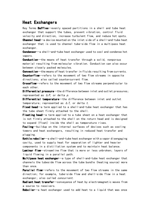
Heat ExchangersKey Terms Baffles—evenly spaced partitions in a shell and tube heat exchanger that support the tubes, prevent vibration, control fluid velocity and direction, increase turbulent flow, and reduce hot spots. Channel head—a device mounted on the inlet side of a shell-and-tube heat exchanger that is used to channel tube-side flow in a multipass heat exchanger.Condenser—a shell-and-tube heat exchanger used to cool and condense hot vapors.Conduction—the means of heat transfer through a solid, nonporous material resulting from molecular vibration. Conduction can also occur between closely packed molecules.Convection—the means of heat transfer in fluids resulting from currents. Counterflow—refers to the movement of two flow streams in opposite directions; also called countercurrent flow.Crossflow—refers to the movement of two flow streams perpendicular to each other.Differential pressure—the difference between inlet and outlet pressures; represented as ΔP, or delta p.Differential temperature—the difference between inlet and outlet temperature; represented as ΔT, or delta t.Fixed head—a term applied to a shell-and-tube heat exchanger that has the tube sheet firmly attached to the shell.Floating head—a term applied to a tube sheet on a heat exchanger that is not firmly attached to the shell on the return head and is designed to expand (float) inside the shell as temperature rises. Fouling—buildup on the internal surfaces of devices such as cooling towers and heat exchangers, resulting in reduced heat transfer and plugging.Kettle reboiler—a shell-and-tube heat exchanger with a vapor disengaging cavity, used to supply heat for separation of lighter and heavier components in a distillation system and to maintain heat balance. Laminar flow—streamline flow that is more or less unbroken; layers of liquid flowing in a parallel path.Multipass heat exchanger—a type of shell-and-tube heat exchanger that channels the tubeside flow across the tube bundle (heating source) more than once.Parallel flow—refers to the movement of two flow streams in the same direction; for example, tube-side flow and shell-side flow in a heat exchanger; also called concurrent.Radiant heat transfer—conveyance of heat by electromagnetic waves from a source to receivers.Reboiler—a heat exchanger used to add heat to a liquid that was onceboiling until the liquid boils again.Sensible heat—heat that can be measured or sensed by a change in temperature.Shell-and-tube heat exchanger—a heat exchanger that has a cylindrical shell surrounding a tube bundle.Shell side—refers to flow around the outside of the tubes of ashell-and-tube heat exchanger. See also Tube side.Thermosyphon reboiler—a type of heat exchanger that generates natural circulation as a static liquid is heated to its boiling point.Tube sheet—a flat plate to which the ends of the tubes in a heat exchanger are fixed by rolling, welding, or both.Tube side—refers to flow through the tubes of a shell-and-tube heat exchanger; see Shell side.Turbulent flow—random movement or mixing in swirls and eddies of a fluid. Types of Heat Exchangers换热器的类型Heat transfer is an important function of many industrial processes. Heat exchangers are widely used to transfer heat from one process to another.A heat exchanger allows a hot fluid to transfer heat energy to a cooler fluid through conduction and convection. A heat exchanger provides heating or cooling to a process. A wide array of heat exchangers has been designed and manufactured for use in the chemical processing industry. In pipe coil exchangers, pipe coils are submerged in water or sprayed with water to transfer heat. This type of operation has a low heat transfer coefficient and requires a lot of space. It is best suited for condensing vapors with low heat loads.The double-pipe heat exchanger incorporates a tube-within-a-tube design. It can be found with plain or externally finned tubes. Double-pipe heat exchangers are typically used in series-flow operations in high-pressure applications up to 500 psig shell side and 5,000 psig tube side.A shell-and-tube heat exchanger has a cylindrical shell that surrounds a tube bundle. Fluid flow through the exchanger is referred to as tubeside flow or shell-side flow. A series of baffles support the tubes, direct fluid flow, increase velocity, decrease tube vibration, protect tubing, and create pressure drops.Shell-and-tube heat exchangers can be classified as fixed head, single pass; fixed head, multipass; floating head, multipass; or U-tube.On a fixed head heat exchanger (Figure 7.1), tube sheets are attached to the shell. Fixed head heat exchangers are designed to handle temperature differentials up to 200°F (93.33°C). Thermal expansion prevents a fixed head heat exchanger from exceeding this differential temperature. It is best suited for condenser or heater operations.Floating head heat exchangers are designed for high temperature differentia is above 200°F (93.33°C).During operation, one tube sheet is fixed and the other “floats” inside the shell.The floatingend is not attached to the shell and is free toexpand.Figure 7.1 Fixed Head Heat ExchangerReboilers are heat exchangers that are used to add heat to a liquid that was once boiling until the liquid boils again. Types commonly used in industry are kettle reboilers and thermosyphon reboilers.Plate-and-frame heat exchangers are composed of thin, alternating metal plates that are designed for hot and cold service. Each plate has an outer gasket that seals each compartment. Plate-and-frame heat exchangers have a cold and hot fluid inlet and outlet. Cold and hot fluid headers are formed inside the plate pack, allowing access from every other plate on the hot and cold sides. This device is best suited for viscous or corrosive fluid slurries. It provides excellent high heat transfer. Plate-and-frame heat exchangers are compact and easy to clean. Operating limits of 350 to 500°F (176.66°C to 260°C) are designed to protect the internal gasket. Because of the design specification, plate-and-frame heat exchangers are not suited for boiling and condensing. Most industrial processes use this design in liquid-liquid service.Air-cooled heat exchangers do not require the use of a shell in operation. Process tubes are connected to an inlet and a return header box. The tubes can be finned or plain. A fan is used to push or pull outside air over the exposed tubes. Air-cooled heat exchangers are primarily used in condensing operations where a high level of heat transfer is required.Spiral heat exchangers are characterized by a compact concentric design that generates high fluid turbulence in the process medium. As do otherexchangers, the spiral heat exchanger has cold-medium inlet and outlet and a hot-medium inlet and outlet. Internal surface area provides the conductive transfer element. Spiral heat exchangers have two internal chambers.The Tubular Exchanger Manufacturers Association (TEMA) classifies heat exchangers by a variety of design specifications including American Society of Mechanical Engineers (ASME) construction code, tolerances, and mechanical design:●Class B, Designed for general-purpose operation (economy and compactdesign)●Class C. Designed for moderate service and general-purpose operation(economy and compact design)●Class R. Designed for severe conditions (safety and durability) Heat Transfer and Fluid FlowThe methods of heat transfer are conduction, convection, and radiant heat transfer (Figure 7.2). In the petrochemical, refinery, and laboratory environments, these methods need to be understood well. A combination of conduction and convection heat transfer processes can be found in all heat exchangers. The best conditions for heat transfer are large temperature differences between the products being heated and cooled (the higher the temperature difference, the greater the heat transfer), high heating or coolant flow rates, and a large cross-sectional area of the exchanger.ConductionHeat energy is transferred through solid objects such as tubes, heads,baffles, plates, fins, and shell, by conduction. This process occurs when the molecules that make up the solid matrix begin to absorb heat energy from a hotter source. Since the molecules are in a fixed matrix and cannot move, they begin to vibrate and, in so doing, transfer the energy from the hot side to the cooler side.ConvectionConvection occurs in fluids when warmer molecules move toward cooler molecules. The movement of the molecules sets up currents in the fluid that redistribute heat energy. This process will continue until the energy is distributed equally. In a heat exchanger, this process occurs in the moving fluid media as they pass by each other in the exchanger. Baffle arrangements and flow direction will determine how this convective process will occur in the various sections of the exchanger.Radiant Heat TransferThe best example of radiant heat is the sun’s warming of the earth. The sun’s heat is conveyed by electromagnetic waves. Radiant heat transfer is a line-of-sight process, so the position of the source and that of the receiver are important. Radiant heat transfer is not used in a heat exchanger.Laminar and Turbulent FlowTwo major classifications of fluid flow are laminar and turbulent (Figure 7.3). Laminar—or streamline—flow moves through a system in thin cylindrical layers of liquid flowing in parallel fashion. This type of flow will have little if any turbulence (swirling or eddying) in it. Laminar flow usually exists atlow flow rates. As flow rates increase, the laminar flow pattern changes into a turbulent flow pattern. Turbulent flow is the random movement or mixing of fluids. Once the turbulent flow is initiated, molecular activity speeds up until the fluid is uniformly turbulent.Turbulent flow allows molecules of fluid to mix and absorb heat more readily than does laminar flow. Laminar flow promotes the development of static film, which acts as an insulator. Turbulent flow decreases the thickness of static film, increasing the rate of heat transfer. Parallel and Series FlowHeat exchangers can be connected in a variety of ways. The two most common are series and parallel (Figure 7.4). In series flow (Figure 7.5), the tube-side flow in a multipass heat exchanger is discharged into the tubeside flow of the second exchanger. This discharge route could be switched to shell side or tube side depending on how the exchanger is in service. The guiding principle is that the flow passes through one exchanger before it goes to another. In parallel flow, the process flow goes through multiple exchangers at the same time.Figure 7.5 Series Flow Heat ExchangersHeat Exchanger EffectivenessThe design of an exchanger usually dictates how effectively it can transfer heat energy. Fouling is one problem that stops an exchanger’s ability to transfer heat. During continual service, heat exchangers do not remain clean. Dirt, scale, and process deposits combine with heat to form restrictions inside an exchanger. These deposits on the walls of the exchanger resist the flow that tends to remove heat and stop heat conduction by i nsulating the inner walls. An exchanger’s fouling resistance depends on the type of fluid being handled, the amount and type of suspended solids in the system, the exchanger’s susceptibility to thermal decomposition, and the velocity and temperature of the fluid stream. Fouling can be reduced by increasing fluid velocity and lowering the temperature. Fouling is often tracked and identified usingcheck-lists that collect tube inlet and outlet pressures, and shell inlet and outlet pressures. This data can be used to calculate the pressure differential or Δp. Differential pressure is the difference between inlet and outlet pressures; represented as ΔP, or delta p. Corrosion and erosion are other problems found in exchangers. Chemical products, heat, fluid flow, and time tend to wear down the inner components of an exchanger. Chemical inhibitors are added to avoid corrosion and fouling. These inhibitors are designed to minimize corrosion, algae growth, and mineral deposits.Double-Pipe Heat ExchangerA simple design for heat transfer is found in a double-pipe heat exchanger.A double-pipe exchanger has a pipe inside a pipe (Figure 7.6). The outside pipe provides the shell, and the inner pipe provides the tube. The warm and cool fluids can run in the same direction (parallel flow) or in opposite directions (counterflow or countercurrent).Flow direction is usually countercurrent because it is more efficient. This efficiency comes from the turbulent, against-the-grain, stripping effect of the opposing currents. Even though the two liquid streams never come into physical contact with each other, the two heat energy streams (cold and hot) do encounter each other. Energy-laced, convective currents mix within each pipe, distributing the heat.In a parallel flow exchanger, the exit temperature of one fluid can only approach the exit temperature of the other fluid. In a countercurrent flowexchanger, the exit temperature of one fluid can approach the inlet temperature of the other fluid. Less heat will be transferred in a parallel flow exchanger because of this reduction in temperature difference. Static films produced against the piping limit heat transfer by acting like insulating barriers.The liquid close to the pipe is hot, and the liquid farthest away from the pipe is cooler. Any type of turbulent effect would tend to break up the static film and transfer heat energy by swirling it around the chamber. Parallel flow is not conducive to the creation of turbulent eddies. One of the system limitations of double-pipe heat exchangers is the flow rate they can handle. Typically, flow rates are very low in a double-pipe heat exchanger, and low flow rates are conducive to laminar flow. Hairpin Heat ExchangersThe chemical processing industry commonly uses hairpin heat exchangers (Figure 7.7). Hairpin exchangers use two basic modes: double-pipe and multipipe design. Hairpins are typically rated at 500 psig shell side and 5,000 psig tube side. The exchanger takes its name from its unusual hairpin shape. The double-pipe design consists of a pipe within a pipe. Fins can be added to the internal tube’s external wall to increase heat transfer. The multipipe hairpin resembles a typical shell-and-tube heat exchanger, stretched and bent into a hairpin.The hairpin design has several advantages and disadvantages. Among its advantages are its excellent capacity for thermal expansion because of its U-tube type shape; its finned design, which works well with fluids that have a low heat transfer coefficient; and its high pressure on the tube side. In addition, it is easy to install and clean; its modular design makes it easy to add new sections; and replacement parts are inexpensive and always in supply. Among its disadvantages are the facts that it is not as cost effective as most shell-and-tube exchangers and it requires special gaskets.Shell-and-Tube Heat ExchangersThe shell-and-tube heat exchanger is the most common style found inindustry. Shell-and-tube heat exchangers are designed to handle high flow rates in continuous operations. Tube arrangement can vary, depending on the process and the amount of heat transfer required. As the tube-side flow enters the exchanger—or “head”—flow is directed into tubes that run parallel to each other. These tubes run through a shell that has a fluid passing through it. Heat energy is transferred through the tube wall into the cooler fluid. Heat transfer occurs primarily through conduction (first) and convection (second). Figure 7.8 shows a fixed head,single-pass heat exchanger.Fluid flow into and out of the heat exchanger is designed for specific liquid–vapor services. Liquids move from the bottom of the device to the top to remove or reduce trapped vapor in the system. Gases move from top to bottom to remove trapped or accumulated liquids. This standard applies to both tube-side and shell-side flow.Plate-and-Frame Heat ExchangersPlate-and-frame heat exchangers are high heat transfer and high pressure drop devices. They consist of a series of gasketed plates, sandwiched together by two end plates and compression bolts (Figures 7.20 and 7.21). The channels between the plates are designed to create pressure drop and turbulent flow so high heat transfer coefficients can be achieved.The openings on the plate exchanger are located typically on one of the fixed-end covers.As hot fluid enters the hot inlet port on the fixed-end cover, it is directed into alternating plate sections by a common discharge header. The header runs the entire length of the upper plates. As cold fluid enters the countercurrent cold inlet port on the fixed-end cover, it is directed into alternating plate sections. Cold fluid moves up the plates while hot fluid drops down across the plates. The thin plates separate the hot and cold liquids, preventing leakage. Fluid flow passes across the plates one time before entering the collection header. The plates are designed with an alternating series of chambers. Heat energy is transferred through the walls of the plates by conduction and into the liquid by convection. The hot and cold inlet lines run the entire length of the plate heater and function like a distribution header. The hot and cold collection headers run parallel and on the opposite side of the plates from each other. The hot fluid header that passes through the gasketed plate heat exchanger is located in the top. This arrangement accounts for the pressure drop and turbulent flow as fluid drops over the plates and into the collection header. Cold fluid enters the bottom of the gasketed plate heat exchanger and travels countercurrent to the hot fluid. The cold fluid collection header is located in the upper section of the exchanger.Plate-and-frame heat exchangers have several advantages and disadvantages. They are easy to disassemble and clean and distribute heat evenly so there are no hot spots. Plates can easily be added or removed. Other advantages of plate-and-frame heat exchangers are their low fluid resistance time, low fouling, and high heat transfer coefficient. In addition, if gaskets leak, they leak to the outside, and gaskets are easy to replace.The plates prevent cross-contamination of products. Plate-and-frame heat exchangers provide high turbulence and a large pressure drop and are small compared with shell-and-tube heat exchangers.Disadvantages of plate-and-frame heat exchangers are that they have high-pressure and high-temperature limitations. Gaskets are easily damaged and may not be compatible with process fluids.Spiral Heat ExchangersSpiral heat exchangers are characterized by a compact concentric design that generates high fluid turbulence in the process medium (Figure 7.22). This type of heat exchanger comes in two basic types: (1) spiral flow on both sides and (2) spiral flow–crossflow. Type 1 spiral exchangers are used in liquid-liquid, condenser, and gas cooler service. Fluid flow into the exchanger is designed for full counterflow operation. The horizontal axial installation provides excellent self-cleaning of suspended solids.Type 2 spiral heat exchangers are designed for use as condensers, gas coolers, heaters, and reboilers. The vertical installation makes it an excellent choice for combining high liquid velocity and low pressure drop on the vapor-mixture side. Type 2 spirals can be used in liquid-liquid systems where high flow rates on one side are offset by low flow rates on the other.Air-Cooled Heat ExchangersA different approach to heat transfer occurs in the fin fan or air-cooled heat exchanger. Air-cooled heat exchangers provide a structured matrix of plain or finned tubes connected to an inlet and return header (Figure 7.23). Air is used as the outside medium to transfer heat away from the tubes. Fans are used in a variety of arrangements to apply forced convection for heattransfer coefficients. Fans can be mounted above or below the tubes in forced-draft or induced-draft arrangements. Tubes can be installed vertically or horizontally.The headers on an air-cooled heat exchanger can be classified as cast box, welded box, cover plate, or manifold. Cast box and welded box types have plugs on the end plate for each tube. This design provides access for cleaning individual tubes, plugging them if a leak is found, and rerolling to tighten tube joints. Cover plate designs provide easy access to all of the tubes. A gasket is used between the cover plate and head. The manifold type is designed for high-pressure applications.Mechanical fans use a variety of drivers. Common drivers found in service with air-cooled heat exchangers include electric motor and reduction gears, steam turbine or gas engine, belt drives, and hydraulic motors. The fan blades are composed of aluminum or plastic. Aluminum blades are d esigned to operate in temperatures up to 300°F (148.88°C), whereas plastic blades are limited to air temperatures between 160°F and 180°F(71.11°C, 82.22°C).Air-cooled heat exchangers can be found in service on air compressors, in recirculation systems, and in condensing operations. This type of heat transfer device provides a 40°F (4.44°C) temperature differential between the ambient air and the exiting process fluid.Air-cooled heat exchangers have none of the problems associated with water such as fouling or corrosion. They are simple to construct and cheaper to maintain than water-cooled exchangers. They have low operating costs and superior high temperature removal (above 200°F or 93.33°C). Their disadvantages are that they are limited to liquid or condensing service and have a high outlet fluid temperature and high initial cost of equipment. In addition, they are susceptible to fire or explosion in cases of loss of containment.。
机械手外文文献翻译2

This is a application of Application Ser. No. 10/799,595, filed on Mar. 15, 2004 now U.S. Pat. No.这是一个应用程序的应用系列号10/799,595,2004 年 3 月15 日美国英保通™技术现在提交。
7,081,700 号。
领域的发明本发明涉及机械手等装配一个微小的对象,例如微型机械组件或单位使用放大镜观察设备如光镜、电镜,或扫描隧道显微镜的分钟部分装配装置或执行诊断、治疗、研究、生物生产、或类似的实际操作,紧凑的机械手装置,例如分钟组织、细胞或生命体和操纵仪器使用机械手分钟对象的基因。
发明背景技术控制的操纵成员轮流使用一般大小轴承和技术的微小的工作,工作装置上执行必要的过程,通过旋转臂一般大小臂或工具沿着拱式指南(例如,日本专利号7-256575)。
在像这些描述的常规仪器上,如果远端的末端不是位于轴承的旋转轴上或拱式指导,远端的出视野的末端移动或深度的姿势控制操作显微镜的重点。
这就需要再次确定显微镜和远端的末端的位置。
正如上文所述,操纵这操作一个微小的对象时的姿态在远端的末端控制,操作的目标对象往往移出显微镜的视野。
其中有三个旋转自由度的常规机械手,特别是因为对应于各自的自由度的旋转轴不配合对方做不相交于一点,远端的末端往往搬出视野或深度聚焦显微镜的应付姿势控制操作。
在这种情况下,在显微镜和远端的末端必须位于再次,此操作需要较长的时间。
本发明的概要它是目前发明提供紧凑的机械手装置解决了上述问题,并操纵微小的目标对象,如机械手的对象和一分钟对象操作器具或类似使用机械手。
为了达到上述目的,根据目前的发明,那里提供机械臂组成:操作的目标对象,操作的成员正在驱动和控制的多元化的自由旋转轴;在穿越的自由旋转轴的所有多元化和操纵远端部分的交集附近放操作的成员。
根据这项安排,机械手有多元化的(通常为三) 自由旋转轴相交于一点,和操纵成员(末端) 的操作手法的目标对象的远端部分位于附近的交叉的机制。
外文翻译 2

附件1:外文资料翻译译文WCDMA系统Ahmed Hassan2.1背景GSM系统最初设计是提供语音和低速率的数据业务。
用户数据速率的无线接口使用单个物理信道,即一个时隙一个TDMA帧,最初速率是9.6 kbps.在第二期GSM系统中,两种新业务通过允许MS占用多个时隙来提高用户数据速率,就是所谓的2.5G。
这两种业务是高速电路交换数据(HSCSD)和通用分组无线服务(GPRS)。
为了在GSM网络上获得更高的数据访问,HSCSD允许个人占用多个连续时隙,而不是限制在GSM TDMA标准中每个用户只占用特定的时隙。
HSCSD为了数据传输放松了GSM标准中原先指定的差错编码控制算法,使可用的应用数据速率达到14.4kbps。
HSCSD让用户通过占用四个连续时隙使传输速率达到57.6kbps。
相比之下,GPRS在无线端口上使用分组连接,仅仅当信息传送时,用户占用一个或多个通信信道。
HSCSD是一种理想的实时互动网络会议,而GPRS 是非实时性的网络应用,包括检索电子邮件、传真、不对称网络浏览。
当GSM 无线信道的八个时隙都分给GPRS时,用户的最高速率可以达到171.2kbps(八个时隙乘以21.4kbps).另一个增加用户数据速率的方法是采用更高层次的调制方案:增强型数据速率GSM演进技术(EDGE)。
EDGE的加强GSM数据速率的背后驱动力是提高调制方法。
EDGE可以根据不同的信道条件在两种调制方式中转换。
EDGE在质量差信道使用GMSK调制方式,在质量好的信道使用8-PSK调制方式。
这是通过借助链路适配功能允许MS和BS根据需要选择这两种不同的调制方式。
因此,调制方式的选择应根据无线链路的质量来提供更高的速率。
EDGE在单一的GSM信道为一个独立专用用户提供高达384kbps的数据速率。
这些选择为通过GSM技术接入网络和支持各种创新手机提供了重大的改善。
然而,所有这些选择对多媒体和巨大的速率依然有限制,这导致了3G系统的改革。
- 1、下载文档前请自行甄别文档内容的完整性,平台不提供额外的编辑、内容补充、找答案等附加服务。
- 2、"仅部分预览"的文档,不可在线预览部分如存在完整性等问题,可反馈申请退款(可完整预览的文档不适用该条件!)。
- 3、如文档侵犯您的权益,请联系客服反馈,我们会尽快为您处理(人工客服工作时间:9:00-18:30)。
本科生毕业设计(论文)外文翻译园林艺术系题目:钢筋混凝土板的拉伸硬化过程分析学生姓名:胡斌学号:200708350209专业班级:土木工程072班指导教师:党改红职称:讲师2011年 3 月 1 日钢筋混凝土板的拉伸硬化过程分析R. Ian Gilbert摘要:当计算一个钢筋混凝土梁或板的承载力时混凝土的抗拉能力通常被忽视,尽管具体的拉应力继续进行,由于拉钢筋到混凝土之间裂缝的转换力量。
这一种混凝土的拉力被称为混凝土的张力硬化。
在开裂后它会影响钢筋混凝土的刚度,因此它的挠度和裂缝宽度必须根据屈服强度负载。
对轻混凝土,例如楼板,全部裂缝的弯曲刚度比没有裂缝部分的要小很多,张力加劲有助于刚度。
在本文中,ACI方法必须考虑到紧张加劲,欧洲和英国的方法是严格评估和预测与实验结果进行比较。
最后,建议书包括建模系统紧张挠度控制的钢筋混凝土楼板设计变硬。
分类号: 1061/ASCE0733-94452007133:6899关键词:开裂;蠕变挠度,混凝土,钢筋,适用性,收缩,混凝土砖。
简介拉伸能力在计算时通常忽略钢筋混凝土梁或板的强度,尽管具体的拉应力继续进行,由于拉钢筋到混凝土之间裂缝的转换力量。
这一种混凝土的拉力被称为张力硬化,它会影响各部分的刚度,因此必须考虑其挠度和裂缝宽度。
随着高强度钢筋的到来,增强混凝土板通常包含相对少量的拉钢筋,经常接近相关建筑法规允许的最低含量。
对于这样的构件,弯曲完全开裂的一个截面刚度比未开裂的截面小许多倍,张力加劲大大促进了开裂后刚度。
在设计中,挠度和裂缝的控制通常是在屈服水平调整考虑的,并在开裂后建模精确的刚度是必需的。
挠度计算中最常用的方法包括确定为破解构件平均惯性(Ie)有效时刻。
几种不同的经验公式可用于Ie,包括著名的方程开发Branson(1965)和ACI 318(ACI 2005)。
其他的张力硬化模式包括在Eurocode 2(CEN1992)和(British Standard BS 8110 1985),最近,Bischoff(2005)表明,布兰森的方程极高估含有少量的钢筋混凝土构件钢筋平均刚度,他提出了一个对于Ie,替代方程,这基本上是与Eurocode 2方案兼容。
在本文中,包括张力加劲的各种方法在混凝土结构设计,包括在Eurocode 2,ACI 318,BS8110模式,批判性进行评估经验预测与实测挠度进行了比较。
最后,在模拟张力加劲的建议结构设计均包括在内。
开裂后弯曲响应考虑简支一个负载变形响应,钢筋混凝土板图1所示。
在负载超过负荷少的开裂,Pcr,该构件未开裂和行为均匀和弹性,以及挠度斜率是成正比的未开裂的转动惯量的转化节,.Iuncr。
该构件在第一裂缝在Pcr当极端纤维在混凝土拉应力的最大部分到达混凝土弯拉强度破裂或.fr有一个刚度突变,并立即出现裂纹。
在包含破碎部分,抗弯刚度显着下降,但大部分仍然未开裂的梁。
随着负载的增加,出现更多的裂缝形式和平均抗弯刚度在整个构件中减少。
如果在梁的混凝土开裂区域进行拉没有压力,负载变形关系将遵循虚线ACD ,图1。
如开裂后如果平均极端纤维拉伸在具体的压力维持在fr ,将遵循虚线AE 。
事实上,实际的响应介于这两个极端,是如图1所示为实线AB 型。
之间的差异实际反映和零张力反应是张力加劲影响。
随着负载的增加,平均拉应力混凝土随着越来越多的裂缝降低对实际的响应趋于零紧张的反应,至少要等到裂缝模式充分开发和裂缝的数量已趋于稳定。
对于含有少量的拉钢筋砖(通常= As/bd0.003),紧张硬化可能超过50%的钢筋混凝土的刚度破坏屈服加载而且仍然要达到和超过的钢产量和负荷接近极限地步。
张力加劲的效果随着时间负荷下降,可能是由于拉伸的综合影响蠕变,蠕变断裂,收缩开裂,而这必须占长期绕度计算。
加劲的张力模型ACI 318-2005梁或板在使用载重挠度可以瞬间从弹性论计算采用混凝土弹性模量Ec 和有效的惯性矩Ie ,例如Ie ,为构件是价值计算Eq.1计算公式为在跨中简支构件和加权平均值计算在连续正,负弯矩区跨度(1)Icr 为换算截面惯性裂的时刻;Ig 为目前的毛质心横截面有关惯性轴,但更应该是正确换算截面的未开裂的惯性力矩Iuncr ;Ma 为在构件的最大弯矩阶段挠度计算;Mcr 为开裂时(=/t t f Ig y );t f 为混凝土断裂模数;t y 为从质心的距离轴的毛截面的纤维在极端的紧张。
ACI 的方法的修改包括在澳大利亚标准AS3600-2001(AS2001)交代的事实,收缩引起的紧张局势可能会降低混凝土开裂时刻显着。
开裂的时刻由公式()/r cs tMcr f f Ig y =-决定,cs f 是最大收缩引起的拉在未开裂截面应力在极端的情况在该纤维发生开裂(Gilbert 2003)。
Eurocode 2(1994)这种方法涉及到在特定的曲率计算交叉部分,然后结合取得的挠度。
开裂后曲率K 的计算为(1-)K Kcr Kuncr ξξ=+ (2)ξ为分配系数占目前水平和打击的程度,并给出2121(/)sr s ξββσσ=- (3) 1β为变形钢筋1.0和光圆钢筋0.5;2β为单一的,短期负荷为1.0和重复或持续荷载为0.5;sr σ在加载应力造成的受拉钢筋首先开裂,计算混凝土紧张;sσ是在考虑钢筋应力加载;Kcr 在截面曲率而忽视具体的紧张;Kuncr 曲率的未开裂换算截面。
在纯弯板,如果压混凝土和钢筋都是线性和弹性,/sr s σσ等于/Mcr Ms ,结合公式1和2能得 (4)对于受弯构件变形钢筋包含短期下载入中,公式3和公式4可以重新安排,以提供下列替代表达式Ie 短期挠度最近提出的计算[Bischoff(2005)](5) BS 8110-1985这种做法,目前已在英国已经取代了欧洲法规2的方法,还涉及到在特定的截面曲率的计算,然后结合取得的偏转。
开裂后的曲率K计算假设1、平面为平截面;2、在压缩和钢筋混凝土被认为是线弹性;3、在紧张的混凝土应力分布是三角形的,曾在中性轴和一个值为零值在1.0 MPa的瞬间强度钢质心,减少至0.55MPa。
与实验数据的比较为了测试ACI 318,欧洲规范的适用性和BS 8110钢筋混凝土构件的轻轻的方法,测瞬间响应与偏转11简支,单钢筋单向拉伸板含钢量在范围0.00180.01ρ<<进行比较和计算的答复,该板块(指定S1至S3,S8的,到SS2的SS4型,和Z1到Z4)都是柱状,矩形截面,850mm,并在一个有效深度载有纵向拉伸单层钢筋d(Es=200000MPa和屈服应力f=500MPa)。
每个板块的详sy细情况见表1,包括有关的几何和材料特性。
在每个板跨中挠度的预测结果与实测时,在跨中时刻等于1.1,1.2和1.3Mcr列于表2。
与瞬时变形响应的测量时刻的两跨中的砖。
(SS2 and Z3)进行比较和计算反应获得图2使用三个代码方式同时显示的反应,如果没有出现开裂,如果紧张僵硬被忽略。
讨论结果很明显,这些轻轻钢筋砖,紧张硬化非常显着,提供了刚度大的比例。
从表2,跨中挠度的比例得到了加劲对测量张力跨中挠度忽视(在Mcr和1.3Mcr范围)是在1.38-3.69范围取平均指2.12。
也就是说,平均而言,紧张硬化超过50%的一个刚性板钢筋在屈服荷载的瞬间开裂。
对于每一个板,在ACI 318的方法低估了瞬间变形开裂后,尤其如此轻率加强板块。
此外,在这一时刻ACI 318突然不模型,偏转方向改变最初的反应开裂,也没有预测的正确形状矩挠度曲线。
在短期挠度低估使用的ACI318模式是经化验报告在这里在表示实践中相当大的比。
不同于Eurocode 2和BS 8110,ACI 318模型不承认或为在开裂的时刻,这将不可避免地减少在实践中出现的由于紧张引起的混凝土干燥收缩或热变形。
对于许多砖,开裂会发生因提前铸造干燥或几周内温度变化,以及经常暴露之前,其板全方位服务的负荷。
通过限制在拉伸的水平拉应力混凝土强化只为1.0 MPa,高估了BS 8110的方法测试的砖都低于并立即偏转以上开裂的时刻。
有道理和损失的刚度,在实践中由于克制,早期收缩和热变形发生膨胀。
不过,BS 8110提供了一个相对较差模型刚度,并错误地认为,平均拉力混凝土裂缝进行了实际调高M增大和中性轴的上升。
因此,斜坡的SB 8110 时刻,挠度情节较陡测量所有板坡。
这种方法使用比欧洲法规2或ACI两种方式也比较繁琐。
在所有情况下,欧洲法规2挠度计算[EPS.(3)-(5)]是在更接近与实测挠度在整个负载范围内协议。
可以看出在图2,载挠度曲线的形状获得使用欧洲规范2是一个比这更好的代表性实际曲线获得使用EP.(1)。
考虑到具体的变异材料性能影响的砖,服务行为和对开裂的随机性,欧洲法规2之间的协议预测和对这种范围广泛的测试结果拉钢筋的比例是相当显着。
随着图2(predicted/exp∆∆)0.80和1.39之间的值平均值为1.07,欧洲法规2的方法提供了ACI318或BS8110更好地估计短期行为。
结论虽然紧张僵硬只对重钢筋梁挠度的影响相对较小,这是非常轻的比例在Iuncr / ICR的是高钢筋构件显着,例如作为最实用的钢筋混凝土楼板。
加劲张力的模型纳入ACI(2005),欧洲法规2(CEN1993),和BS8110(1985) 已提交其适用性已轻轻钢筋混凝土楼板评估。
计算模型的三个代码瞬时挠度进行了比较与来自11个实验室测试测量挠度在含有不同数量的钢筋砖。
在欧洲法规2方案(EP.(5)已被证明是更准确地模拟了瞬时负载变形的加固构件轻轻响应的波形和ACI 318(EP.(1)比更为可靠的方法。
出自:JOURNAL OF STRUCTURAL ENGINEERING © ASCE / JUNE 2007Tension Stiffening in Lightly Reinforced Concrete Slabs1R. Ian Gilbert1Abstract:The tensile capacity of concrete is usually neglected when calculating the strength of a reinforced concrete beam or slab, even though concrete continues to carry tensile stress between the cracks due to the transfer of forces from the tensile reinforcement to the concrete through bond. This contribution of the tensile concrete is known as tension stiffening and it affects the member’s stiffness after cracking and hence the deflection of the member and the width of the cracks under service loads. For lightly reinforced members, such as floor slabs, the flexural stiffness of a fully cracked section is many times smaller than that of an uncracked section, and tension stiffening contributes greatly to the postcracking stiffness. In this paper, the approaches to account for tension stiffening in the ACI, European, and British codes are evaluated critically and predictions are compared with experimental observations. Finally, recommendations are included for modeling tension stiffening in the design of reinforced concrete floor slabs for deflection control.DOI:10.1061/(ASCE)0733-9445(2007)133:6(899)CE Database subject headings:Cracking; Creep; Deflection; Concrete, reinforced; Serviceability; Shrinkage; Concrete slabs.1Professor of Civil Engineering, School of Civil and EnvironmentalEngineering, Univ. of New South Wales, UNSW Sydney, 2052, Australia.Note. Associate Editor: Rob Y. H. Chai. Discussion open untilNovember 1, 2007. Separate discussions must be submitted for individualpapers. To extend the closing date by one month, a written request mustbe filed with the ASCE Managing Editor. The manuscript for this technicalnote was submitted for review and possible publication on May 22,2006; approved on December 28, 2006. This technical note is part of theJournal of Structural Engineering, Vol. 133, No. 6, June 1, 2007.©ASCE, ISSN 0733-9445/2007/6-899–903/$25.00.11Professor of Civil Engineering, School of Civil and Environmental Engineering, Univ. of New South Wales, UNSW Sydney, 2052, Australia.Journal of Structural Engineering, Vol. 133, No. 6, June 1, 2007.©ASCE, ISSN 0733-9445/2007/6-899–903/$25.00.IntroductionThe tensile capacity of concrete is usually neglected when calculatingthe strength of a reinforced concrete beam or slab, eventhough concrete continues to carry tensile stress between thecracks due to the transfer of forces from the tensile reinforcementto the concrete through bond. This contribution of the tensileconcrete is known as tension stiffening, and it affects the member’sstiffness after cracking and hence its deflection and thewidth of the cracks.With the advent of high-strength steel reinforcement, reinforcedconcrete slabs usually contain relatively small quantities oftensile reinforcement, often close to the minimum amount permittedby the relevant building code. For such members, the flexuralstiffness of a fully cracked cross section is many times smallerthan that of an uncracked cross section, and tension stiffeningcontributes greatly to the stiffness after cracking. In design, deflectionand crack control at service-load levels are usually thegoverning considerations, and accurate modeling of the stiffnessafter cracking is required.The most commonly used approach in deflection calculationsinvolves determining an average effective moment of inertia [Ie]for a cracked member. Several different empirical equations areavailable for Ie, including the well-known equation developed byBranson [1965] and recommended in ACI 318 [ACI 2005]. Othermodels for tension stiffening are included in Eurocode 2 [CEN1992] and the [British Standard BS 8110 1985]. Recently,Bischoff [2005] demonstrated that Branson’s equation grossly overestimates thtie average sffness of reinforced concrete memberscontaining small quantities of steel reinforcement, and heproposed an alternative equation for Ie, which is essentially compatiblewith the Eurocode 2 approach.In this paper, the various approaches for including tensionstiffening in the design of concrete structures, including the ACI318, Eurocode 2, and BS8110 models, are evaluated critically andempirical predictions are compared with measured deflections.Finally, recommendations for modeling tension stiffening instructural design are included. Flexural Response after CrackingConsider the load-deflection response of a simply supported, reinforcedconcrete slab shown in Fig. 1. At loads less than thecracking load, Pcr, the member is uncracked and behaves homogeneouslyand elastically, and the slope of the load deflection plotis proportional to the moment of inertia of the uncracked transformedsection, I uncr. The member first cracks at Pcr when theextreme fiber tensile stress in the concrete at the section of maximum moment reaches the flexural tensile strength of the concrete or modulusof rupture, fr . There is a sudden change in the local stiffness at and immediately adjacent to this first crack. On the section containing the crack, the flexural stiffness drops significantly, but much of the beam remains uncracked. As load increases, more cracks form and the average flexural stiffness of the entire member decreases.If the tensile concrete in the cracked regions of the beam carried no stress, the load-deflection relationship would follow the dashed line ACD in Fig. 1. If the average extreme fiber tensile stress in the concrete remained at fr after cracking, the loaddeflection relationship would follow the dashed the actual response lies between these two extremes and is shown in Fig. 1 as the solid line AB. The difference between the actual response and the zero tension response is the tension stiffening effect ( in Fig. 1).As the load increases, the average tensile stress in the concrete reduces as more cracks develop and the actual response tends toward the zero tension response, at least until the crack pattern is fully developed and the number of cracks has stabilized. For slabscontaining small quantities of tensile reinforcement [typicallytension stiffening may be responsible for morethan 50% of the stiffness of the cracked member at service loads and remains significant up to and beyond the point where the steel yields and the ultimate load is approached]. The tension stiffening effect decreases with time under sustained loads, probably due to the combined effects of tensile creep, creep rupture, and shrinkage cracking, and this must be accounted for in long-term deflection calculations.Models for Tension StiffeningACI 318-2005The instantaneous deflection of beam or slab at service loads may be calculated from elastic theory using the elastic modulus of concrete Ec and an effective moment of inertia, Ie . The value of Ie for the member is the value calculated using Eq. [1] at midspan for a simply supported member and a weighted average value calculated in the positive and negative moment regions of a continuous span33()1-cr cr e g cr g a a ⎡⎤M M ⎛⎫I =I +I ≤I ⎢⎥ ⎪M M ⎝⎭⎢⎥⎣⎦ (1)where Icr =moment of inertia of the cracked transformed section;Ig =moment of inertia of the gross cross section about the centroidal axis [but more correctly should be the moment of inertia of the uncracked transformed section, I uncr]; Ma =maximum moment in the member at the stage deflection is computed; Mcr =cracking moment =(frIg / yt ); fr =modulus of rupture of concrete (=7.5 fc in psi and 0.6 fc in Mpa); and yt =distance from the centroidalaxis of the gross section to the extreme fiber in tension.A modification of the ACI approach is included in the Australian Standard AS3600-2001 (AS 2001)to account for the fact that shrinkage-induced tension in the concrete may reduce the cracking moment significantly. The cracking moment is given by Mcr =(fr − fcs )Ig / yt , where fcs is maximum shrinkage-induced tensile stress in the uncracked section at the extreme fibre at which cracking occurs (Gilbert 2003).(1-)K Kcr Kuncr ξξ=+ (2)where ξdistribution coefficient accounting for moment level and degree of cracking and is given by2121(/)sr s ξββσσ=- (3)and 1=1.0 for deformed bars and 0.5 for plain bars; 2=1.0 for a single, short-term load and 0.5 for repeated or sustained loading; sr =stress in the tensile reinforcement at the loading causing first cracking (i.e., when the moment equals Mcr ), calculated while ignoring concrete in tension; s is reinforcement stress at loading under consideration (i.e., when the in-service moment Ms is acting), calculated while ignoring concrete in tension; cr =curvature at the section while ignoring concrete in tension; and uncr=curvature on the uncracked transformed section.For slabs in pure flexure, if the compressive concrete and the reinforcement are both linear and elastic, the ratio sr /s in Eq.(3) is equal to the ratio Mcr /Ms . Using the notation of Eq.(1), Eq.(2) can be reexpressed as()1Ms Ms Ms EcIe EcIcr EcIuncr ξξ⎛⎫⎛⎫=+- ⎪ ⎪⎝⎭⎝⎭ (4)For a flexural member containing deformed bars under shortterm loading, Eq. (3) becomes =1−(Mcr /Ms )2 and Eq.(4)can be rearranged to give the following alternative expression for Ie for short-term deflection calculations [recently proposed by Bischoff (2005)]:2/1Icr Mcr Ie Icr Iuncr Ms ⎡⎤⎛⎫⎛⎫=- ⎪ ⎪⎢⎥⎝⎭⎝⎭⎣⎦ (5)BS 8110-1985This approach, which has now been superseded in the U.K. by the Eurocode 2 approach, also involves the calculation of the curvature at particular cross sections and then integrating to obtain the deflection. The curvature of a section after cracking is calculated by assuming that (1) plane sections remain plane; (2) the concrete in compression and the reinforcement are assumed to be linear elastic; and (3)the stress distribution for concrete in tension is triangular, having a value of zero at the neutral axis and a value at the centroid of the tensile steel of 1.0 MPa instantaneously, reducingto 0.55 MPa in the long term.Comparison with Experimental DataTo test the applicability of the ACI 318, Eurocode 2, and BS 8110 approaches for lightly reinforced concrete members, the measured moment versus deflection response for 11 simplysupported, singly reinforced one-way slabs containing tensile steel quantities in the<0.01 are compared with the calculated responses. The slabs (designated range 0.0018<S1 to S3, S8, SS2 to SS4, and Z1 to Z4) were all prismatic, of rectangular section, 850 mm wide, and contained a single layer of longitudinal tensile steel reinforcement at an effective depth d (with Es=200,000 MPa and the nominal yield stress fsy=500 Mpa). Details of each slab are given in Table 1, including relevant geometric and material properties. The predicted and measured deflections at midspan for each slab when the moment at midspan equals 1.1, 1.2, and 1.3 Mcr are presented in Table 2. The measured moment versus instantaneousdeflection response at midspan of two of the slabs (SS2 and Z3) are compared with the calculated responses obtained using the three code approaches in Fig. 2. Also shown are the responses if cracking did not occur and if tension stiffening was ignored. Discussion of ResultsIt is evident that for these lightly reinforced slabs, tension stiffening is very significant, providing a large proportion of the postcracking stiffness. From Table 2, the ratio of the midspan deflection obtained by ignoring tension stiffening to the measured midspan deflection (over the moment range Mcr to 1.3 Mcr)is in the range 1.38–3.69 with a mean value of 2.12. That is, on average, tension stiffening contributes more than 50% of the instantaneous stiffness of a lightly reinforced slab after cracking at service load.For every slab, the ACI 318 approach underestimates the instantaneous deflection after cracking, particularly so for lightly reinforced slabs. In addition, ACI 318 does not model the abrupt change in direction of the moment-deflection response at first cracking, nor does it predict the correct shape of the postcracking moment-deflection curve.The underestimation of short-term deflection using the ACI318 model is considerably greater in practice than that indicated by the laboratory tests reported here. Unlike the Eurocode 2 and BS 8110 approaches, the ACI 318 model does not recognize or account for the reduction in the cracking moment that will inevitably occur in practice due to tension induced in the concrete by drying shrinkage or thermal deformations. For many slabs, cracking will occur within weeks of casting due to early drying or temperaturechanges, often well before the slab is exposed to its full service loads.By limiting the concrete tensile stress at the level of the tensile reinforcementto just 1.0 MPa, the BS 8110 approach overestimates the deflection of the test slabs bothbelow and immediately above the cracking moment. This is not unreasonable and accountsfor the loss of stiffness that occurs in practice due to restraint to early shrinkageand thermal deformations. Nevertheless, the BS 8110 approach provides a relatively poormodel of thepostcracking stiffness and incorrectly suggests that the average tensile force carriedby the cracked concrete actually increases as M increases and the neutral axis rises.As a result, the slope of the BS 8110 postcracking moment-deflection plot is steeper thanthe measured slope for all slabs. The approach is also more tedious to use than eitherthe ACI or Eurocode 2 approaches.In all cases, deflections calculated using Eurocode 2[ Eqs.(3)–(5)] are in muchcloser agreement with the measured deflection over the entire postcracking load range.As can be seen in Fig. 2, the shape of the load-deflection curve obtained using Eurocode2 is a far better representation of the actual curve than that obtained using Eq. (1).Considering the variability of the concrete material properties that affect thein-service behavior of slabs and the random nature of cracking, the agreement betweenthe Eurocode 2 predictions and the test results over such a wide range of tensile∆∆) in Table reinforcement ratios is quite remarkable. With the ratio of (predicted/exp2 varying between 0.80 and 1.39 with a mean value of 1.07, the Eurocode 2 approach certainlyprovides a better estimate of short-term behavior than either ACI 318 or BS8110. Conclusion sAlthough tension stiffening has only a relatively minor effect on the deflection ofheavily reinforced beams, it is very significant in lightly reinforced members where theratio I uncr / Icr is high, such as most practical reinforced concrete floor slabs. Themodels for tension stiffening incorporated in ACI (2005), Eurocode 2 (CEN 1992), andBS 8110 (1985) have been presented and their applicability has been assessed for lightlyreinforced concrete slabs.Instantaneous deflections calculated using the three codemodels have been compared with measured deflections from 11 laboratory tests on slabscontaining varying quantities of steel reinforcement. The Eurocode 2 approach (Eq.(5)has been shown to more accurately model the shape of the instantaneousload-deformation response for lightly reinforced members and be far more reliable thanthe ACI 318 approach (Eq.(1).ReferencesAmerican Concrete Institute (ACI).(2005). “Building code requirements for structural concrete.” ACI 318-05, ACI Committee 318, Detroit.Bischoff, P. H. (2005). “Reevaluation of deflection prediction for concrete beams reinforced with steel and fiber-reinforce polymer bars.” J.Struct. Eng., 131(5), 752–767.Branson, D. E. (1965). “Instantaneous and time-dependent deflections ofsimple and continuous reinforced concrete beams.” HPR Rep. No. 7,1, Alabama Highway Dept., Bureau of Public Roads, Ala.British Standards Institution (BS).(1985). “Structural use of concrete,Part 2, code of practice for special circumstances.” BS8100: Part2:1985, British Standard, London, England.European Committee for Standardization(CEN). (1992). “Eurocode 2:Design of concrete structures Part 1-1: Genera l rules for buildings.”DD ENV 1992-1-1, European Prestandard, Brussels, Belgium.Gilbert, R. I.(2003). “Deflection by simplified calculation in AS3600-2001—On the determination of fcs.” Australian J. Structural Engineering,5(1), 61–71. Standards Australia(AS). (2001). “Australian standard for concrete structures.”AS 3600-2001, Sydney, Australia.JOURNAL。