奇石乐发动机燃烧分析仪说明书
燃烧分析仪手册
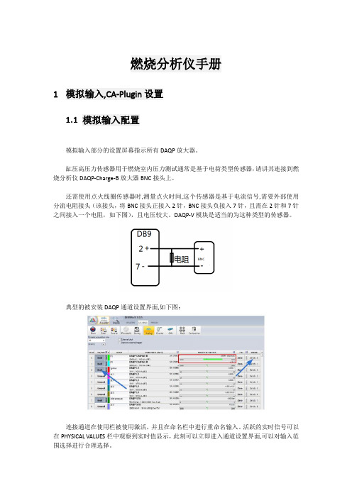
燃烧分析仪手册1模拟输入,CA-Plugin设置1.1模拟输入配置模拟输入部分的设置屏幕指示所有DAQP放大器。
缸压高压力传感器用于燃烧室内压力测试通常是基于电荷类型传感器,请讲其连接到燃烧分析仪DAQP-Charge-B放大器BNC接头上。
还需使用点火线圈传感器时,测量点火时间,这个传感器是基于电流信号,需要外部使用分流电阻接头(该接头,将BNC接头正接入2针,BNC接头负接入7针,且需在2针和7针之间接入一个电阻,如下图),且电压较大。
DAQP-V模块是适当的为这种类型的传感器。
典型的被安装DAQP通道设置界面,如下图:连接通道在使用栏被使用激活,并且在命名栏中进行重命名输入。
活跃的实时信号可以在PHYSICAL VALUES栏中观察到实时值显示,此刻可以立即进入通道设置界面,可以对输入范围选择进行合理选择。
在通道设置中对各放大器设置,用户可以定义和扩展。
通道设置分为4步,如下图由第一步到第四步说明进行通道设置。
第一步,放大器量程设置;第二步,通道名称和单位设置;第三步,传感器灵敏度设置(两点法、公式法);第四步,显示输入值(物理量)和对应实际值(工程量)。
●输入范围可以从预定义列表选择,或手工输入。
●抗混叠过滤器应该设置为100 khz和贝塞尔模型。
高压力传感器暴露在热冲击环境下,这可能会导致信号漂移,但AC耦合方式将减少这种漂移,避免信号超过他们的输入范围。
高通滤波器的频率与输入范围相关联。
在从100pC到2000pC时为0.07Hz,超过2000pC约0.005 Hz高通滤波器参数。
●连接传感器后后可以将耦合设置到DC模式,并点击Reset。
Reset将消除连接及长时间运行放大器内把引起和产生的内部静电,将信号只调回到0。
●点火线圈传感器设置,仍遵循上述的四步方法,量程只需满足要求即可,可以无需设置灵敏度参数,因为,此传感器主要关注的是,点火时间,而非电流大小。
1.2CA-Plugin设置模拟输入设置后,我们必须选择燃烧分析插件设置,并添加计算模板。
奇石乐KiBox燃烧分析仪功能简介

奇石乐燃烧分析仪——KiBox简介一、仪器设备名称: KiBox Combustion AnalysisKiBox燃烧分析系统二、厂商:瑞士奇石乐仪器股份公司Kistler Instrumente AG国别:瑞士Switzerland三、型号: 2893AK1四、技术特点及优势✓KiBox燃烧分析仪可以用于发动机台架标准稳态燃烧分析———燃烧热力学计算、示功图、爆震分析、燃烧噪声分析、压力升高率分析、瞬时放热率和累计放热率分析,并得到峰值压力、压力升高率、燃烧重心、燃烧持续期、平均有效压力、爆震强度、爆震峰值、爆震频率、燃烧循环波动、燃烧温度、发动机循环功及功率、点火正时、喷油始点终点、喷射持续期等发动机燃烧特征参数。
✓KiBox燃烧分析仪可用于发动机高瞬态工况燃烧分析,更可以用于车载燃烧分析,获得真实驾驶条件的燃烧分析和优化结果, 如海拔、沙漠、低温等条件。
✓无需光电编码器,可以将各种车载转角传感器和触发码盘信号转换为精确可靠的曲轴转角信号,并且在高瞬态的发动机工况下利用车载转角信号(e.g. 60-2、60-2-2、60-2-2-2、60-1、36-2、24-1等)获得所需要的 0.1 CA 转角分辨率✓对于磁电传感器系统基于转速进行角度误差的修正,允许对触发信号进行修正(触发信号标定的需要),实现零相位延迟。
✓智能信号调理模块,自动识别传感器标定数据并导入。
✓提供车辆行驶条件下发动机上止点的确定。
✓同时获得角域和时域数据,并灵活切换。
✓强大的参数配置界面,独立的数据显示。
具有校验输入信号的诊断功能,自动校验参数设置的有效性。
✓基于每循环燃烧分析的操控性试验,比如扭矩响应。
✓实时的每循环燃烧效率和功率信息,例如,MFB50表示了循环间变化对燃油效率的影响;IMEP 涉及到各缸工作的稳定性及缸间平衡程度。
✓缸内压力的上升率表征了NVH质量的变化。
✓发动机起动质量试验:排放、失火、怠速平稳性。
可测试记录发动机启动前30s和发动机停机后30s的数据。
奇石乐kibo燃烧分析仪应用lya
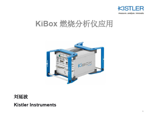
Direct CN
(directly generated by the cylinder pressure attenuation)
Indirect CN
(attenuated by the cylinder pressure but generated by mechanics)
Lya 2014 KiBox Application
Lya 2014 KiBox Application
22
5. 汽油机标定 主要关注参数
Lya 2014 KiBox Application
23
6. 柴油机标定 主要关注参数
AI50
Lya 2014 KiBox Application
RMAX : Maximum rise per degree crank angle
爆震 残余气体 能量平衡 喷射特性 发动机功率
Lya 2014 KiBox Application
2
热动力学分析
Lya 2014 KiBox Application
3
1. 柴油机喷射参数优化
Lya 2014 KiBox Application
4
2. 汽油机爆震分析 (Knock Analysis)
useful for invehicle testing
Lya 2014 KiBox Application
20
4. 与标定软件 ATI VISION 集成
Offline Analysis
Lya 2014 KiBox Application
21
5. 汽油机标定 主要关注参数
KPeak : Knock Peak AI50 : Location of 50% burnt mass fraction IMEP_cov : Variant coefficient over a certain number of cycles
燃烧分析仪燃烧说明
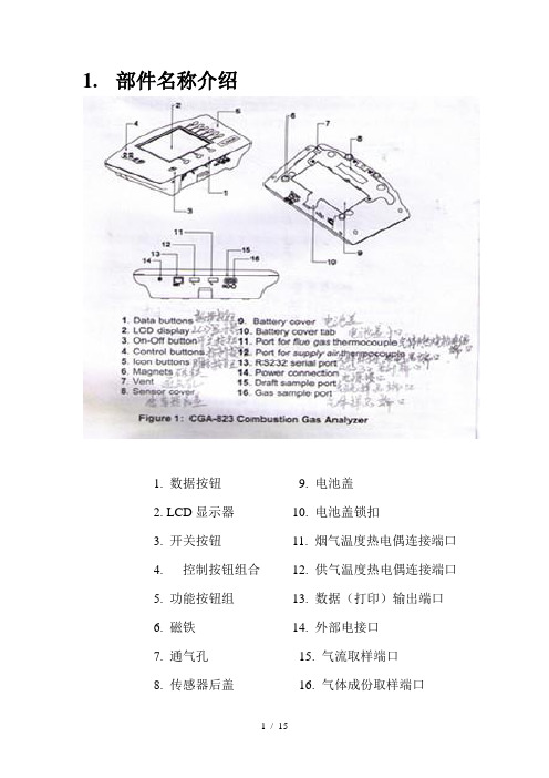
1.部件名称介绍1. 数据按钮9. 电池盖2. LCD显示器10. 电池盖锁扣3. 开关按钮11. 烟气温度热电偶连接端口4. 控制按钮组合12. 供气温度热电偶连接端口5. 功能按钮组13. 数据(打印)输出端口6. 磁铁14. 外部电接口7. 通气孔15. 气流取样端口8. 传感器后盖16. 气体成份取样端口1. 部件名称介绍1. 装置固定管 6. 热电偶连接头2.探针手柄 7. 取样软管 3. 安放、紧固装置 8. 集水器 4. 取样管 9. 水份过滤器 5.带热电偶的探针头1234 567892.入门指南接通电源CGA-823分析仪运转需用4节C号(3号)电池或一个AC电源适配器。
电池安装注意+、- 极的方向。
使用电源适配器时注意:本仪器所配适配器AC电源额定电压为:110V AC.如若使用适配器请务必首先确认电源电压。
▲取样探针连接如上图所示将热电偶插头、气体、气流取样管接头与分析仪主机相连,①热电偶插头由两个宽带不同的插片组成。
相连时只能有唯一的插入方向,不可强行连接。
②连接气流、气体取样软管时注意,气体取样软管只有单一的接头,气流软管则在旁边附加一个直径稍小的开口软管,两根软管连接时相对位置应与主机上所示截面图形一致。
3.基本操作启动①初始参数校正,将取样探针从采集管中取出或不连接取样软管。
②选择空气新鲜的地方按动开关按钮,屏幕显示启动初始反应。
如下图若无错误,屏幕会显示主要参数信息。
按动选择按钮,各界面信息如下图所示,我们在检测前需确认O2(20.9%), CO ,CO2,NO X等初始数值是否为“0”若以上各项都无错误,则可将取样探针插入想要测量的气体管道中取样。
等待一会儿待数据稳定后读取。
4.维护保养清空聚水器参考下图。
在聚水器第一室中液态水行程作为气体被从暖气管中取样,聚水器这样的设计是当摇动或方向更改时,水不会流过第二室,然而水位必须保持低于图中7所示的位置。
1首先将取样软管与集水器底部图中3位置断开。
KIMO 燃烧分析仪说明书
COMBUSTION ANALYSERS Domestic & industrial heatingFrench Manufacturer• 2 interchangeable sensors • Remote printer (option)• Thermocouple K input for DHW network• Supplied with calibration certificate, Ligaz-2 software, protective shell and storage bag• O 2 and CO sensors • Remote printer (option)• Thermocouple K input for DHW network • Supplied with adjustment certificate and storage bag• 2 interchangeable sensors• Sensor protection by pump shutdown • Integrated printer• Supplied with calibration certificate, Ligaz-2 software, protective shell and storage bagCOMPACTKigaz 80ECONOMICALKigaz 50ESSENTIALKigaz 110Combustion analysersGas analysis / Temperature / PressureKigazThe new Kigaz analysers are intended for efficiency monitoring and optimisation and for limiting emissions from all types of boiler.This new range of combustion analysersprovides practical solutions to improve working life in the field.O 2• Up to 3 interchangeable sensors • CO sensor protection by solenoid valve • Auto-zero in flue • Integrated printer• Supplied with calibration certificate, Ligaz-2 software, protective shell and storage bag • Changeable probe length• Up to 4 interchangeable sensors • CO dilution up to 5%• Auto-zero in flue • Integrated printer • Integrated condensate trap • 3 pressure sensors• Supplied with calibration certificate, Ligaz-2 software, protective shell and storage case FLEXIBLEKigaz 210EXPERTKigaz 310Advantages.....................04Software . . . . . . . . . . . . . . . . . . . . . . .05Kigaz 310 . (06)Kigaz 210 ......................08Kigaz 110 ......................09Kigaz 80 .. (10)Kigaz 50 .......................11Accessories (11)SummaryP . 05P . 04Mobile application compatible with the entire Kigaz range*.Easy user replacement, no need to return to the factory*.Kigaz mobileInterchangeable sensors*Excluding Kigaz 50The advantagesof the Kigaz rangeWith a colour or black-and-white screen, our new combustiongas analysers have an ergonomic design enablingmeasurements to be made as easily as possible by means of:• A 10 button keypad• An intuitive graphical interfaceAvailable as an option, the low consumption Bluetooth mo-dule is compatible with all Kigaz units (excluding the class 50)and provides significant time gains by wirelessly connectinganalysers with LIGAZ-2 or LOGAZ-2 software or the mobileKigaz application.Connected appliancesEasy to useInterchangeable sensorsThe sensor electronics contain calibration data,which means that the operator can replace themwithout returning the unit to the factory.Kimo equips its Kigaz units with a lead-free O2sensor with a lifetime of 5 years.Bluetooth®connectionLong lifeO2sensorProtective rubbershellFREEappDISPONIBLE SUR6Kigaz 310The Kigaz 310 is the most comprehensive in the range and isconfigurable to your requirements, with four interchangeable sensors.The expertCODilution Long life O 2 sensor Auto-zeroin the flue Mobile applicationIntegrated printerDHW network 2 thermocouple K inputsBluetooth ®connectionUp to 4interchangeable sensorsChangeable probe lengthThe Kigaz 310 adapts to any standard-based constraint and meets all of your requirements.Access to the sensors is straightforward, and theoperator can replace them without returning the unit to the factory.For still more accurate measurements, the Kigaz 310 is equipped with 3 pressure sensors, enabling:• measurement of differential pressure with manualauto-zero• high accuracy draught measurement withauto-zero by solenoid valve• measurement of pump flow with 3 levels ofregulation, blocked filter compensation and seal testing3 pressure sensorsUp to 4 interchangeable sensorsIntegrated condensate trapSave time with the Kigaz 310’s integratedcondensate trap. The trap provides the security of overflow-free measurement and warns you when the maximum level is reached.The filter integrated into the handle of the probe is easy to replace.O 2L V / CO-H 2 / NO / NO 2 / SO 2 / CH 4interchangeableMaximum level alarmAutomatic pump controlKigaz 210Flexible and accurate, the Kigaz 210 makes all of your operations simple. It offers a range of configurable measurements according to your requirements, and its icon-based navigation system makes it very easy to use.The flexible unitUp to 3interchangeable sensorsMobile applicationIntegrated printerO 2LV / CO-H 2 NO / CH 4interchangeable CO sensor protection by solenoid valveSupplied with CALIBRATIONcertificateAuto-zero in the flue Changeable probe lengthThe Kigaz 110 combustion gas analyser is the idealappliance for rapid use on all types of boiler up to 400 kW.Easy to use and sturdy, it allows the main inspection pointsto be examined.The essential unitLong lifeO2sensorMobileapplicationIntegratedprinterO2L V / CO-H2interchangeableSensor protectionby pump shut-downDHW network1 thermocouple KinputSupplied withCALIBRATIONcertificateWith a light, compact design, the Kigaz 80 provides allthe necessary functions to accurately measure the maincombustion data for a domestic boiler up to 400 kW. The compact unitMobileapplicationRemoteprinterO2/ CO-H2interchangeableSensor protectionby pumpshutdownDHW network1 thermocouple KinputSupplied withCALIBRATIONcertificateKigaz 50functions in a compact unit, enabling you to take reliable sets of measurements from domestic boilers up to 400 kW.The economical unit2 fixed sensorsAuto-zero 30 secondsOptionRemote printerKimo at your service in more than 150 countriesD o c C o m b u s t i o n - V 1 - A n g l a i s - 12/17 R C S (24)P ér i g u e u x 349 282 095 - D o c u m e n t n o n c o n t r a c t u e l - N o u s n o u s r és e r v o n s l a p o s s i b i l i t é d e f a i r e év o l u e r l e s c a r a c t ér i s t i q u e s d e n o s p r o d u i t s s a n s p r éa v i s**************More information。
奇石乐KiBox 燃烧分析仪应用 _ Lya

4.
KPEAK_STAT : Knock Peak Statistic
Lya 2014
KiBox Application
7
2. 汽油机爆震分析 (监控)
Evaluation methods: 5. Limit monitoring :
Trigger storage Digital output
V2.0
பைடு நூலகம்
additionally
Indication results are transferred via CAN to testbed controller
AVL IndiCom Serial Testbed Protocol via RS232 or Ethernet
2013
Lya 2014 KiBox Application
Lya 2014 KiBox Application 33
3. CAN Monitoring
Configure CAN database
Lya 2014
KiBox Application
34
3. CAN Monitoring
KiBox CAN data displayed in a device accepts CAN data
Lya 2014
KiBox Application
27
1. Misfire 失火分析
0.6
0.4 IMEP1 bar IMEP2 bar IMEP3 bar IMEP4 bar 0 50 100 150 200 250
0.2
Evaluation parameter:
300 IMEP
0
-0.2
-0.4
燃烧分析仪手册

燃烧分析仪手册————————————————————————————————作者:————————————————————————————————日期:燃烧分析仪手册1模拟输入,CA-Plugin设置1.1模拟输入配置模拟输入部分的设置屏幕指示所有DAQP放大器。
缸压高压力传感器用于燃烧室内压力测试通常是基于电荷类型传感器,请讲其连接到燃烧分析仪DAQP-Charge-B放大器BNC接头上。
还需使用点火线圈传感器时,测量点火时间,这个传感器是基于电流信号,需要外部使用分流电阻接头(该接头,将BNC接头正接入2针,BNC接头负接入7针,且需在2针和7针之间接入一个电阻,如下图),且电压较大。
DAQP-V模块是适当的为这种类型的传感器。
典型的被安装DAQP通道设置界面,如下图:连接通道在使用栏被使用激活,并且在命名栏中进行重命名输入。
活跃的实时信号可以在PHYSICALVALUES栏中观察到实时值显示,此刻可以立即进入通道设置界面,可以对输入范围选择进行合理选择。
在通道设置中对各放大器设置,用户可以定义和扩展。
通道设置分为4步,如下图由第一步到第四步说明进行通道设置。
第一步,放大器量程设置;第二步,通道名称和单位设置;第三步,传感器灵敏度设置(两点法、公式法);第四步,显示输入值(物理量)和对应实际值(工程量)。
●输入范围可以从预定义列表选择,或手工输入。
●抗混叠过滤器应该设置为100 khz和贝塞尔模型。
高压力传感器暴露在热冲击环境下,这可能会导致信号漂移,但AC耦合方式将减少这种漂移,避免信号超过他们的输入范围。
高通滤波器的频率与输入范围相关联。
在从100pC到2000pC时为0.07Hz,超过2000pC约0.005Hz高通滤波器参数。
●连接传感器后后可以将耦合设置到DC模式,并点击Reset。
Reset将消除连接及长时间运行放大器内把引起和产生的内部静电,将信号只调回到0。
●点火线圈传感器设置,仍遵循上述的四步方法,量程只需满足要求即可,可以无需设置灵敏度参数,因为,此传感器主要关注的是,点火时间,而非电流大小。
FEV CAS燃烧分析仪的使用入门
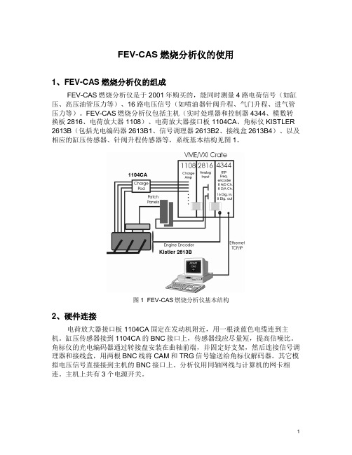
FEV-CAS燃烧分析仪的使用1、FEV-CAS燃烧分析仪的组成FEV-CAS燃烧分析仪是于2001年购买的,能同时测量4路电荷信号(如缸压、高压油管压力等)、16路电压信号(如喷油器针阀升程、气门升程、进气管压力等)。
FEV-CAS燃烧分析仪包括主机(实时处理器和控制器4344、模数转换板2816、电荷放大器1108)、电荷放大器接口板1104CA、角标仪KISTLER 2613B(包括光电编码器2613B1、信号调理器2613B2、接线盒2613B4)、以及相应的缸压传感器、针阀升程传感器等,系统基本结构见图1。
1104CAKistler 2613B图1 FEV-CAS燃烧分析仪基本结构2、硬件连接电荷放大器接口板1104CA固定在发动机附近,用一根淡蓝色电缆连到主机。
缸压传感器接到1104CA的BNC接口上,传感器线应尽量短,提高信噪比。
角标仪的光电编码器通过转接盘安装在曲轴前端,并固定好支架,然后连接信号调理器和接线盒,用两根BNC线将CAM和TRG信号输送给角标仪解码器。
其它模拟电压信号直接接到主机的BNC接口上。
分析仪用同轴网线与计算机的网卡相连。
主机上共有3个电源开关。
3、计算机设置3.1 网卡设置①、将3Com的PCMICA网卡插入笔记本电脑后,Windows XP会自动为其安装驱动。
需要做一些设置才能使用。
②、从开始/控制面板/网络连接,找到3Com网卡的连接(图1),点右键选属性,打开网卡的属性界面(图2),点击配置(C)...打开网卡的配置界面。
图3 网卡属性界面③、网卡的配置界面中选高级,将TransceiverType由TP(RJ-45)改为Coax(BNC) (图3),将FullDuplex改为Enabled (图4)。
点确定后回到网卡的属性界面。
图4 更改网卡接口类型图5 启用网卡全双工④、找到Internet协议(TCP/IP),点击属性后将网卡的IP地址设为10.203.0.53,点确定完成网卡设置。
燃烧分析仪手册修订稿

燃烧分析仪手册WEIHUA system office room 【WEIHUA 16H-WEIHUA WEIHUA8Q8-燃烧分析仪手册1模拟输入,CA-Plugin设置1.1模拟输入配置模拟输入部分的设置屏幕指示所有DAQP放大器。
缸压高压力传感器用于燃烧室内压力测试通常是基于电荷类型传感器,请讲其连接到燃烧分析仪DAQP-Charge-B放大器BNC接头上。
还需使用点火线圈传感器时,测量点火时间,这个传感器是基于电流信号,需要外部使用分流电阻接头(该接头,将BNC接头正接入2针,BNC接头负接入7针,且需在2针和7针之间接入一个电阻,如下图),且电压较大。
DAQP-V模块是适当的为这种类型的传感器。
典型的被安装DAQP通道设置界面,如下图:连接通道在使用栏被使用激活,并且在命名栏中进行重命名输入。
活跃的实时信号可以在PHYSICAL VALUES栏中观察到实时值显示,此刻可以立即进入通道设置界面,可以对输入范围选择进行合理选择。
在通道设置中对各放大器设置,用户可以定义和扩展。
通道设置分为4步,如下图由第一步到第四步说明进行通道设置。
第一步,放大器量程设置;第二步,通道名称和单位设置;第三步,传感器灵敏度设置(两点法、公式法);第四步,显示输入值(物理量)和对应实际值(工程量)。
●输入范围可以从预定义列表选择,或手工输入。
●抗混叠过滤器应该设置为100 khz和贝塞尔模型。
高压力传感器暴露在热冲击环境下,这可能会导致信号漂移,但AC耦合方式将减少这种漂移,避免信号超过他们的输入范围。
高通滤波器的频率与输入范围相关联。
在从100pC到2000pC时为,超过2000pC约 Hz 高通滤波器参数。
●连接传感器后后可以将耦合设置到DC模式,并点击Reset。
Reset将消除连接及长时间运行放大器内把引起和产生的内部静电,将信号只调回到0。
●点火线圈传感器设置,仍遵循上述的四步方法,量程只需满足要求即可,可以无需设置灵敏度参数,因为,此传感器主要关注的是,点火时间,而非电流大小。
奇石乐KiBox燃烧分析仪功能简介

奇石乐燃烧分析仪——KiBox简介一、仪器设备名称: KiBox Combustion AnalysisKiBox燃烧分析系统二、厂商:瑞士奇石乐仪器股份公司Kistler Instrumente AG国别:瑞士Switzerland三、型号: 2893AK1四、技术特点及优势✓KiBox燃烧分析仪可以用于发动机台架标准稳态燃烧分析———燃烧热力学计算、示功图、爆震分析、燃烧噪声分析、压力升高率分析、瞬时放热率和累计放热率分析,并得到峰值压力、压力升高率、燃烧重心、燃烧持续期、平均有效压力、爆震强度、爆震峰值、爆震频率、燃烧循环波动、燃烧温度、发动机循环功及功率、点火正时、喷油始点终点、喷射持续期等发动机燃烧特征参数。
✓KiBox燃烧分析仪可用于发动机高瞬态工况燃烧分析,更可以用于车载燃烧分析,获得真实驾驶条件的燃烧分析和优化结果, 如海拔、沙漠、低温等条件。
✓无需光电编码器,可以将各种车载转角传感器和触发码盘信号转换为精确可靠的曲轴转角信号,并且在高瞬态的发动机工况下利用车载转角信号(e.g. 60-2、60-2-2、60-2-2-2、60-1、36-2、24-1等)获得所需要的 0.1 CA 转角分辨率✓对于磁电传感器系统基于转速进行角度误差的修正,允许对触发信号进行修正(触发信号标定的需要),实现零相位延迟。
✓智能信号调理模块,自动识别传感器标定数据并导入。
✓提供车辆行驶条件下发动机上止点的确定。
✓同时获得角域和时域数据,并灵活切换。
✓强大的参数配置界面,独立的数据显示。
具有校验输入信号的诊断功能,自动校验参数设置的有效性。
✓基于每循环燃烧分析的操控性试验,比如扭矩响应。
✓实时的每循环燃烧效率和功率信息,例如,MFB50表示了循环间变化对燃油效率的影响;IMEP 涉及到各缸工作的稳定性及缸间平衡程度。
✓缸内压力的上升率表征了NVH质量的变化。
✓发动机起动质量试验:排放、失火、怠速平稳性。
可测试记录发动机启动前30s和发动机停机后30s的数据。
奇石乐发动机燃烧分析仪说明书
压阻式压力传感器
压阻原理以1954年首次发现的半导体 效应为基础,即在机械应力作用下, 半导体的阻值会发生变化。与传统的 应变仪测量相比,这一发现开拓了全 新的应用领域。从那时起,其他相近 的技术开始出现,如金属薄膜技术和 陶瓷厚膜技术。
开始: – 奇石乐 – 传感器型号 – 版本 – 传感器版本号 – 传感器序号
初始校准: – 工作温度范围 – 初始校准日期 – 初始校准值
再校准: – 参考温度 – 再校准日期 – 再校准值
结尾: – 注释
传感器
密封
连接电缆
传感器、连接电缆和 TEDS 元件
PiezoSmart®适配器
压阻式低压
压电式缸压
PiezoStar®-10 多年来奇石乐在厂内培养高灵 敏和高温稳定的晶体。
2
目录
从晶体到传感器需要 200 道工序
4
奇石乐压力传感器 - 设计的多样化和创新
6
PiezoSmart® 意味着传感器的自动识别
8
技术先驱 - 引导发动机测试技术发展
压电式缸压
PiezoSmart® 传感器
优点概述
● 电荷和电压放大器参数的自动设 置
● 精确压力指示数据测量简便 ● 简化设置过程缩短试验台的测量
准备时间 ● 通过分析系统数据自动交换,简
化测量分析和记录 ● 传感器自动识别技术极大地提高
多通道校准系统的自动化程度
更多关于升级的信息, 请参考第 18 页
燃烧 排气气体分析仪筛选器应用说明说明书

Background:There are many requirements through-out industry where combustion/flue gases must be analyzed and recorded periodically for compliance to EPA regulations and to ensure maximum efficiency of the combustion device (burner/boiler).Instrumentation used to perform this analysis are adversely effected by condensed contaminates, acidic and sulfuric gases and solid contaminates. These contaminates can skew the analysis but more importantly ruin the internals of the instrument to the point where a complete rebuild is required. Efficient removal of undesirable con-taminates from a sample stream will ensure accurate analysis and trouble-free operation of the instrumentation.Features and benefits:• Ideal for the following liquid filtration applications:Filtration of liquid with minimum holdup volumeFiltration of liquid samples to analyzersLow Cost DisposableFilters for Flue/Combustion Gas AnalysisMarket Application Publication • Ideal for the following gas filtration applications:Final filter for air logic devices Protection of pneumatic components Filtration of portable environmental sampling devicesFiltration of samples to on-line analyzersProtection of Pneumatic temperaturecontrols• Additional applications in the following industries:Instrument & Controls HVAC Dental Automotive Food PackagingApplication:Typical applications for sample filtration include stack gas or emissions sam-pling. These sampling applications have specific and unique filtration require-ments depending on the analysis tobe performed and the contaminates present in the sample stream. Quantita-tive measurement of excess oxygen, carbon dioxide and nitrogen oxides are unique to stack and flue gas sampling. Coalescing filtration is used widely in most sampling applications as an initial filtration stage to remove all condens-ables. Additional secondary filtration requirements for removal of specific gas contaminates is best accomplished by using a specialized bed of adsorbent.In most stack and flue gas sampling applications, instruments are most ad-versely affected by sulfur based acidic gases. These gases will condense and quickly corrode and ruin the sensitive sensors and internals of these instru-ments. The secondary filter recommen-dation for removal of these contaminate gases should be an adsorbent bed . In most applications a specialized formu-lation of sodium and calcium hydrox-ides is the ideal media to remove these gases. Case Study:A large company located in Michigan,specializing in combustion diagnos-tics and optimization relies on manyof the instruments they manufactureto perform very specialized analysis inwhat is considered to be the most ag-gressive application found in industry– combustion/flue gas sampling. Thiscompany provides a diagnostic servicethat pinpoints areas where customerscan reduce fuel costs, increase boilerefficiencies/generation and reduce NOxemissions.One instrument that is manufacturedby this company and used extensivelyto perform critical analysis is the MSCAor multi-stream combustion analyzer.Capable of sampling up to 12 flue gasstreams simultaneously on a real timebasis, these instruments require highefficiency filtration to safe guard againstthe corrosive acidic vapor gases. Priorexperience with inappropriate filtrationresulted in costly rework of the instru-mentation, additional travel and laborexpenses to return to the test site anddelayed service to their customers.The Parker Balston® disposable filterunit packed with a mixed sodium andcalcium hydroxide adsorbent mate-rial are used on all these instruments.In applications where excessive con-densate is expected, a Parker Balstondisposable filter unit assembled witha high efficiency coalescing filter isinstalled upstream from the adsorbentfilter which protects the adsorbentfrom becoming saturated and renderedinoperable. These filter combinationshave resulted in flawless analysis withno downtime, no rework to the equip-ment and timely, expedient service totheir customers.Recognized as the industry leaderin sample filtration and conditioning,Parker Balston flue gas filters are foundin the majority of all instruments andanalyzers as a supplied component.Combustion Gas AnalyzersFilterBalston brand disposable filter units (DFU) consist of a microfiber filter cartridgepermanently bonded into a sealed plastic holder with 125 psig pressure ratings,temperatures to 275°F, and available in low and high flow models. The economicalDFU offers all of the advantages of microfiber filter cartridges for high efficiency liq-uid and gas filtration, combined with the economics and convenience of completedisposability.Disposable Filter Units (DFUs)Balston Disposable Filter UnitsDisposable Adsorption Units (DAUs) contain a bed of adsorbent granules. Utiliz-ing a wide choice of adsorbents, the DAUs selectively remove vapors from air and other gases.Because the adsorbed vapor remains trapped in the solid bed, the DAU has a fixed upper limit of total weight of vapor which can be captured. It is usually not feasible to regenerate the filter when it has reached its adsorption limit. DAUs should be used only when small quantities of vapor are to be removed.Selecting a Disposable Adsorption UnitThe following factors should be considered when selecting a DAU:1 Solid adsorbents are effective only for vapors. Since liquids will damage or inactivate most solid adsorbents, the DAU must be preceded by an efficient coalescing filter.2 In contrast with Microfiber Filters, which operate at their initial efficiency through-out their life, adsorbent cartridges have a limited holding capacity. When the adsorption capacity is reached, no further adsorption occurs. The limiting capac-ity, or “breakthrough” point, is not sharply defined, and the exit vapor concentra-tion will increase rapidly as saturation is approached. To avoid unwanted vapor contaminants downstream, it is necessary to change the adsorbent cartridge well before it has reached its ultimate adsorption capacity.3 Adsorption is reversible; if operating conditions change, a vapor may desorb rather than adsorb. For example, if a temporary surge in vapor impurity con-centration causes a relatively high concentration to be adsorbed on the solid, a subsequent decrease in inlet vapor composition will result in desorption of vapor from the solid to the gas stream.4 The efficiency of a given adsorbent for a given vapor depends upon the specific operating conditions. Therefore, again in contrast to filtration, it is not possible to assign a single efficiency rating to an adsorbent. While it is not possible to pre-dict or guarantee an adsorption efficiency for any specific set of conditions, it is possible to enhance the conditions beneficial to adsorption and avoid condi-tions which interfere with adsorption. Conditions which aid adsorption are: low temperature, high pressure, low flow rate, and absence of competing vapors (particularly water vapor).Adsorbent Grade Use For Carbon 000 Compressor oil vapors, C 5 and heavier hydrocarbons, aromatics, oxygenated hydrocarbons, chlorinated organics, freons, carbon disulfide.Silica Gel 101 Recommended only for water vapor.Molecular 103 Most C 4 and lighter hydrocarbons, ethylene, propylene, Sieve acetylene, ethylene oxide, ammonia, mercaptans, sulfur Type 13X hexafluoride, triethylamine, and smaller amines.Mixed 107 All acidic gases, including sulfur trioxide, sulfur dioxide, nitrogen dioxide, Sodium & carbon dioxide, hydrogen sulfide, hydrogen chloride, phosphorus Calciumtrichloride, boron trifluoride.HydroxidesDisposable Adsorption Units (DAUs)Models 9922-05, 9933-05, 4433-05 and 9900-05The 99XX-05 models are the smallest Disposable Filter Units with 11.7 ml inter-nal volume. These models are used in low flow gas or liquid sampling applica-tions, such as liquids to specific-ion analyzers or gases to personal samplers. The model 9900-05-BK has a color indicating feature, which turns the cartridge red when saturated with oil. The model 4433-05 has 1/4” and 3/8” Barb Connections molded into the inlet/outlet ports.Models 9922-11, 9933-11, and 8800-12Models 9922-11, 9933-11, and 8800-12 are used for applications similar to the smaller DFUs (Models 9922-05 and 9933-05) which require greater solids holding capacity and can tolerate the increased retention time.Model 8833-11These Disposable Filter Units are used as continuous coalescing filters with a third port serving as the drain, slip-stream, or by-pass port.Model 9953-11This model snaps together for easy filter cartridge changeouts. It is designed primarily for low pressure or mild vacuum applications. It is ideal for capturing samples and perform analysis or record weights over time. If used with a X-tube, it is a very effective silencer to suppress inlet noise to small pumps.Parker Hannifin offers a manual drain valve for removal of coalesced liquids from the Type 8833-11-DX.Drain Valve: 1/8” NPT (male) x 1/8” ID Tubing. (Requires elbow part No. 11972). Part No. 20-125Model99XX-05Model 4433-05Model 9953-11 1.22”Model 8833-11Model 9922-11Model 8800-122.24”Features and benefits:• Prevent cross-contamination of samples• Pressure ratings up to 125 psig • Temperature to 275°F (135°C)• Completely disposable, constructed of recyclable plasticsChemical Compatibility Models 9922-05, 9922-11, 8833-11, and 8800-12Suitable:Water or steam to 200°F (135°C); concentrated nitric, sulfuric, and hydrochloric acids; chlorine (gas or liquid); sodium hypochlorite, ethylene oxide (gas or liquid); Freons; ammonia (gas, liquid, or aqueous solutions); hydrogen peroxide (all concentrations); bromine (dry and aqueous solutions); all chlorinated solvents except methylene chloride; all aromatic and aliphatic solvents; all alcohols and glycols; aniline; phenol.Limited Use:Acetone, MEK, dioxane, furfural, methylene chloride.Unsuitable: Water above 200°F (135°C), THF, DMF, ethylene diamine, chlorosulfonic acid, etha-nolamine, pyridine, sulfur trioxide.Chemical Compatibility Model 9933-11Suitable:Water to 158°F (70°C); benzene, toluene, other aromatic hydrocarbons; hydrocarbon solvents and fuels, perchloroethylene; trichloroethylene, nitric acid (to 10%); sulfuric acid (to 40%); hydrochloric acid (to 10%); most salt solutions; sodium and potassium hydroxide (to 50%). Limited Use:Water at 176°F (80°C); acetone; MEK, acetaldehyde; ammonia (to 25%). Unsuitable: Water above 158°F (70°C); alcohols; glycols, phenol; aniline; DMF; concentratedacids; chlorine.Flow RatesWater Flow Rate, Gallons per HourDFU Model Volume of Housing Initial Pressure Grade Grade Grade Grade Grade Gallons Liters Drop DQ, DX CQ, CX BQ, BX AQ AAQ 9922-05 0.003 0.01 1 psi 12 10 3 1.5 0.4 4433-05 5 psi 30 25 15 7.3 1.9 9933-059922-11 0.0005 0.02 1 psi 18 15 5 2.5 0.6 9933-11 5 psi 45 37 26 12 3.1 8800-12 1 psi 54 44 13 6 1.45 psi 129 106 56 26 6.5Model 2 psig 20 psig 40 psig 60 psig 80 psig 100 psig 125 psig 9953-11-DX, 8833-11-DX (7) 1.8 3.6 5.8 8.0 10.0 12.0 14.60.9 1.8 2.9 4.0 5.0 6.0 7.38833-11-BX9953-11-BX,0.4 0.8 1.3 1.8 2.2 2.7 3.34433-05-BX9900-05-BK,Principal SpecificationsModel 9922-05 9900-05 4433-05 9933-05 9922-11 9933-11 8833-11 8800-12 9953-11 Inlet and Outlet Ports 1/4” Tubing 1/4” Tubing 1st Tier/Barb 1/4”Tube 1/4” Tubing 1/4” Tubing 1/4” Tubing 1/4” Tubing 1/2” Tubing 0.32” OD2nd Tier/Barb 3/8”TubeDrain None None None None None None 1/4” Tubing None None Material of Construction PVDF Nylon Nylon Nylon PVDF Nylon Nylon Nylon Polypropylene Filter Cartridge Length 1.25” (3.2 cm) 1.25” (3.2 cm) 1.25” (3.2cm) 1.25” (3.2 cm) 2.25” (5.7 cm) 2.25” (5.7 cm) 2.25” (5.7 cm) 2.25” (5.7 cm) 2.28” (6.35 cm) Maximum Temperature (1) 275°F (135°C) 230°F (110°C) 230°F (110°C) 230°F (110°C) 275°F (135°C) 230°F (110°C) 230°F (110°C) 150°F (66°C) 125°F (52°C) Maximum Pressure (2) 125 psig 125 psig 125 psig 125 psig 125 psig 125 psig 125 psig 50 psi (5) 2 psi Dimensions 1.0”D X 3.25”L 1.0”D X 3.25”L 1.0”D X 3.43”L 1.0”D X 3.25”L 1.4”D X 4.6”L 1.4”D X 4.6”L 1.4”D X 4.6”L 2.24”D X 6.24”L 1.22”D X 3.57”L(2.5 cm X 8 cm) (2.5 cm X 8 cm) (2.5 cm X 8.72 cm) (2.5 cm X 8 cm) (3.6 cm X 12 cm) (3.6 cm X 12 cm) (3.6 cm X 12 cm) (5.69 cm X 15.85 cm) (3.1 cm X 9.07 cm) Ordering InformationModel 9922-05 9900-05 4433-05 9933-05 9922-11 9933-11 8833-11 8800-12 9953-11 Box of 10 DFUs 9922-05-❑ (4) 9900-05-❑ (4) 4433-05-❑ (4) 9933-05-❑ (4) 9922-11-❑ (5) 9933-11-❑ (5) 8833-11-❑ (6) 8800-12-❑ box of 1 (5) 9953-11-❑ (5) Available only in Q-gradesBox 10 DAU’S (3) 9922-05-❑ N/A 4433-05-❑ 9933-05-❑ 9922-11-❑ 9933-11-❑ N/A N/A N/A1 At 0 psig2 At 110°F (43°C)3 To designate adsorbent in the DAU, insert adsorbent numbers after DAU designation.For example, to obtain a miniature clear nylon DAU with carbon adsorbent, order 9933-05-000. Adsorbent numbers are listed on page 33.4 Available only in Q grades.5 Available in Q or X media.6 Available only in X media.7 9953-11 is designed for maximum pressure of 2 psig.8 Pressure rating in liquid service is 70 PSIG maximum.Installation InformationTo pressure pipe or tubing:Compression fittings for 1/4” O.D. tubing may be obtained from the following manufacturers.Hoke, Inc. (“Gyrolok”); Crawford Fitting Co. (“Swagelok”); Parker-Hannifin Corp. (“CPI”); Legris, Inc. (push-on fittings); Jaco Mfg. Co. (plastic fittings). The fol-lowing brass fittings which seal by O-ring compression and which may be completely recovered and reused when changing filters may be purchased from Parker/Balston:Connector: 1/4” tubing to 1/4” NPT female -Part No. 11970 (1 per pkg.)Connector: 1/4” tubing to 1/4” tubing -Part No. 11971 (1 per pkg.)To low pressure plastic tubing:Tubing with 1/4” ID may be slipped over the DFU and fittings and held with tubing clamps.Parker Hannifin supplies plastic barbs to connect the DFU to smaller diameter plastic tubing. The connection is suitable for pressures to 50 psig.DFU to 1/16” ID tubing: Part No. 14000 (bag of 20 barbs)DFU to 1/8” ID tubing: Part No. 14001 (bag of 20 barbs)MAP FlueGas-C 05/2015© 2010, 2015 Parker Hannifin CorporationParker Hannifin CorporationIndustrial Gas Filtration andGeneration Division4087 Walden Ave.Lancaster, NY 14086。
燃烧分析仪使用说明书
燃烧分析仪使用说明书**燃烧分析仪使用说明书**一、简介燃烧分析仪是一种用于测定固体、液体或气体中元素含量的仪器。
它采用燃烧法,通过燃烧物料并利用检测装置测量特定元素的浓度。
本说明书将详细介绍燃烧分析仪的使用方法以及注意事项。
二、仪器操作步骤1. 准备工作在使用燃烧分析仪之前,需要确保设备连接正常,并检查供气、供液系统是否正常工作。
同时,确认样品的准备工作已完成,如将固体物料粉碎并溶解到合适的溶剂中。
2. 打开仪器按下电源开关,等待燃烧分析仪启动。
系统启动后,将屏幕设置为所需参数显示。
3. 样品准备取出一个空白样品容器,并用去离子水彻底清洗。
将待测样品精确地称量到容器中,并确保容器密封良好。
4. 装载样品将样品容器放入样品台,并通过仪器软件操作选择所需的分析方法。
5. 启动分析过程按下仪器的“启动”按钮,燃烧分析仪将自动进行燃烧分析过程。
此过程中,仪器将自动设定燃烧温度、保持时间和检测参数。
6. 结果分析待燃烧分析过程完成后,系统将生成测试结果。
用户可以在仪器显示屏上查看、记录和导出结果数据。
三、使用注意事项1. 安全使用使用过程中要确保操作人员具备一定的实验室操作经验,并严格按照操作规程进行。
注意使用耐火手套和防护眼镜等个人防护措施,以避免可能的伤害。
2. 设备维护定期进行设备检查和维护,以确保仪器的正常工作。
特别是对液氮供应系统和燃烧室进行清洁和检查,以保证分析结果的准确性。
3. 样品准备在进行燃烧分析之前,样品需经过充分的制备工作,确保样品的精确称量和密封。
同时,根据待测元素特点,选择适当的溶剂。
4. 操作环境使用燃烧分析仪的实验室应保持清洁和整洁,避免尘埃和杂质的干扰。
保持适宜的温度和湿度,以确保仪器的工作效果。
5. 结果分析在结果分析过程中,注意根据实际需求进行数据处理,并确保数据的准确性。
及时导出和记录测试结果,以备后续分析和参考。
四、故障排除1. 仪器无法启动检查电源是否连接正常,确保供电正常。
燃烧测试仪操作手册翻译

遵守UL94标准的燃烧测试仪操作手册目录1.说明和技术数据2.安全提示3.操作元件3.1主开关3.2计时器3.3气体供应/火焰防护3.4燃烧室打火3.5烟筒3.6远距离控制3.7流速控制3.8初始压力控制3.9燃烧位置和角度调整3.10样条夹持位置调整3.11灰烬抽屉4.测试过程5.保养,调校和售后服务附录A:准备和开机B:附件C:燃烧仪火焰校正1.说明和技术数据W AZAU UL94燃烧室是一个可更换的测试设备。
除了能够进行UL 94垂直和水平测试外,还可以建模依据其他标准进行测试。
为了保证使用的耐久性和耐腐蚀性,如果标准没有特别规定,测试室及其附件用不锈钢制成。
试样的位置和排列范围很大。
燃烧器角度可调整。
此装置提供内部打火,窗口可视面积大,有一个抽屉可收集燃烧后的废弃物,有排放系统能够将测试区域燃烧后产生的气体排出。
下面这些设备的具体数值限定了燃烧室的应用。
基于微处理器的控制单元包含自动试火保护,记录时间范围从0.2s-100min的多级计时器和燃烧器功率调校模式以满足标准化需求。
2.安全提示燃烧测试仪主要涉及大量的安全危害,这些危害需要注意采取不同的安全预防措施。
使用测试仪的人员仅限于那些受过培训,知道和了解操作手册内容的人。
操作人员应该有能力独立识别危险,必要情况下能够采取安全措施。
操作人员应该知道目前的规范,标准和安全保护条例,这些都是操作人员进行测试时必须考虑到的。
有毒气体,燃烧和爆炸危险在燃烧期间,特别是塑料样品可能放出有害气体。
一旦试火保护出现故障或有毒气体泄露,可能积聚在室内外。
仪器开着时,不要让仪器无人值守。
当你离开时,关闭气源供应开关。
当你离开之前,完全打开观察窗。
测试过程中不能打开观察窗。
只要样品还在燃烧,就不可以打开观察窗。
燃烧室未被排空,不可以打开观察窗。
如果在附近闻到气味,不要操作仪器。
由于实验过程中所用的氧气来源于周围环境,请确保仪器周围空气流动通畅。
电流危险仪器须在带有接地安全保护系统,符合VDE。
BDN Automotive CA-6 燃烧分析仪用户手册说明书

BDN Automotive® CA-6Combustion Analyser USER MANUALIntroductionSustainability is the key of the future of motorsport, such as the consumer car market. Thus, advanced development technologies must be used to increase the efficiency of the currently used loud, stinky but thrilling power units. Combustion analysis is the first step on this route, which is currently a privilege of high-class motorsport teams and OEM-s. BDN Automotive® offers a simple and understandable combustion analyser for less than 20% of the cost of current devices on the market. Not only the price, but extraordinary user-friendly graphical interface makes this device remarkable amongst our competitors.CA-6 is an easy to use combustion analyser developed mainly for the motorsport sector. In the following document You will see all the necessary information to be able to use our product immediately, without days or weeks of setup and calibration.We do not take any responsibility for any damage (direct/indirect/consequential or any kind) caused by BDN Automotive® CA-6, although, this is a measurement only device, does not have anydirect control over the ECU parameters!BDN Automotive® CA-6 is not certified to be used on public roads, off-road use only!Use at your own risk!Made In EUContentsGeneral parameters (3)Pinout (4)Sensors (6)Additional information (6)Hall effect sensor (6)Pressure sensor channel measurement ranges (device speci fic according to the customer’s requirements) (7)Using with Kistler charge amplifier (7)Combustion analysis backgrounds (8)Software (8)Setup (9)Measure (13)Analyse (16)General parametersPinoutSOURIAU 8STA61435SN PLUG, contact size #22DSensorsAll sensors delivered by BDN Automotive are equipped with MIL-Spec connectors:•Sensor side: SOURIAU 8STA10635PN•Wiring loom side: SOURIAU 8STA60635SNAdditional informationHall effect sensorCompatible sensor type: active low NPN/open-drain output hall effect sensor, e.g.: Bosch HA-PIf the Engine Management Unit and the BDN CA-6 are connected to the same Hall effect sensor, and the sensor is power supplied from the Engine Management Unit, use a 1 conductor shielded cable to connect the signal to the BDN CA-6’s Hall sensor input [pin 4 or 5]. Connect the cable shield to pin 6.Pressure sensor channel measurement ranges (device specific according to the customer’s requirement s)Using with Kistler charge amplifierCharge amplifier setup:•Drift Compensation(DrCo) mode•Low-Pass Filter: LP off•Voltage Output Scaling: Offset 0VBefore starting a measuring cycle with pressing the Meas button on the amplifier, the BDN CA-6 must be in powered state (pin 29 and 30 connected to +12V power supply/battery), otherwise the charge amplifier’s output signal may cause permanent hardware dama ges.Connecting to BDN CA-6:Combustion analysis backgroundsCombustion analysisSoftwareThe software has been created to achieve a simple but effective layout in order to maximise the product effectiveness. This is the world’ first freely available combustion analysis software, however it is only compatible with BDN Automotive’s products.The software allows the user to perform real-time measurements and also to prepare log files that can be further investigated using the Analyse window. Log files can also be created with the help of the cycle counter that is mainly used for steady state points, and for cycle averaged results.The software description will be detailed on the following pages.SetupThe main setup window allows the user to define all necessary engine parameters and measuring modes. When defining the engine parameters, a maximum precision needs to be kept as they are heavily influencing combustion analysis parameters.Setup fileAll engine parameters can be stored in a setup file in order to make changes easier between engines. Setup files can be stored or loaded via the next icons.GeneralUnder the General window the user can define the measurement modes and parameters in connection with Measure window.User Interface ModeUser int erface mode allows to select between “Basic” and “Pro” modes. The selection infl uences the layout of Measure window. “Basic” mode shows only the vital parameters for a quick overlook and “Pro” allows to capture more information for an engineer with more experience. Important to mention that the interface mode selection is not influencing the information recorded in log files!Measuring modeMeasuring mode allows to select between “single cycle” and “average of cycles” functions.That has influence on Measure window. In “single cycle” mode every cycles are separately visible and can be recorded. In “average of cycles” mode only the averaged values of a given amount of cycles is visible. That mode is usually used for steady state points on rolling roads or engine dynos.More differences shown under the description of Measure window.UnitsThe user can switch between Metric or Imperial units.Maximum engine revolutionDefines the tacho limits under Measure window.EngineUnder Engine window the vital parameters of the given engine needs to be specified. All geometric parameters have to be defined within the tolerance of +/- 0.1mm, in order to get the most accurate results from the background computations.CrankshaftUnder the crankshaft window the crankshaft sensor and trigger wheel parameters needs to be defined. BDN CA-6 supports both variable reluctant and Hall type sensors. As there is a multiple option to connect trigger sensors the connected channel also need to be selected. (e.g.: VR1/VR2) At crankshaft triggerwheel setup the user can select from the most widespread OEM patterns. (Upon request unique patterns can be defined. However, we highly recommend to use 60-2 pattern to increase accuracy.) It is recommended to use the nominal TDC reference position for a given engine. That value will be overridden during the TDC initialization process in Pressure function.PressureThis window allows the user to define the pressure sensors built in the given engine and to define the exact TDC reference point used for the given setup file.TDC reference point determination mode:For the TDC reference point determination the engine needs to be used for a short period in fuel-cut (without combustion) mode. Speed the engine up to 2000-2500 Rpm, than inhibit injection in the ECU for 2-3 s. Press TDC search (??) button in the software while the injection is inhibited. The reference point position will be instantly updated. Only cylinders with pressure sensors can be for reference cylinders!Will be available later!MeasureMeasure window is used for data display under real-time measuring conditions and creating log files. The measure window has different layouts depending on the chosen modes in Setup window. The different functions and possibilities will be detailed separately for all conditions.Basic UIM, Single cycle:This measuring mode is generally used for real time, transient measurements, when the only the most important variables needs to be displayed.T he window’s left side features the log creation with the followingpossibilities:Log files can be created with different length. For a given amount of datathe limited length of log can be used, where a log counter creates the endof the log file. For other kinds of measurements “Continuous log” can beused, where the user defines the log file end by pressing “Stop log”.The mid part of the window shows the most important cycle variables andthe pressure curve real time per each cycle.The cursor on the top helps to set the demanded area of the pressure curve graph, therefore it is possible to focus on the most important part of the cycle. (gas exchange, combustion, etc. ) Beside that the demanded cylinders can be selected for data display. By double clicking on the graphs’limiting numbers and setting the new limits the graph can be reshaped.The tacho and the table below shows the current cycle data, such as Peak Pressure, Knock Peak Amplitude [bar], and MassFractionBurned50 [CrA°] for every cylinders.On the right side of the window the history graphs are displayed. There the most important recent cycle values can be traced back, in order not to miss any events.Pro UIM, Single cycle:The Pro mode is very similar the previously detailed basic mode, however, with more variablesshown in the history graphs.Average of cycles modeIn the average of cycles mode has been created to better observe and evaluate calibration changes in steady state points. Parameter fluctuations due to cycle variance is commonly observable, thereforereal-time data evaluation could be problematic.The page layout seems very similar to the previous UIMs. The upper table and graph show the averaged values and the lower ones show the fluctuation of the parameters. It is highlyrecommended to average at least 100 cycles to ensure accuracy and repeatability!AnalyseAnalyse window allows the user to evaluate log files created under Measure window. Log files can be loaded through the next part of the window.The analysed cylinders can be selected through the cylinder selector part. The selected cylinders will be displayed with the tick’s colour.Cycles in main windowThe analyse main window features a list of history graphs that indicate the most important recorded variables through the measurement. The cursor that selects the given cycle can be moved in the RPM window.On the right side of the window the current average (throughout the measurement) values are indicated for each variable. By right clicking on the graphs the data from the windows can be copied and used in other programs.Cycles in floating windowMain window show the history graphs of a given log file and gives insight only to cycle variables. Sometimes, a detailed insight into a cycle is also necessary, therefore cycles can be opened in a floating window as well.The data from the floating window can be copied in the same way as from the main window.。
发动机综合检测仪说明书()

DLFJ-2000型发动机综合检测仪使用说明书深圳安车科技有限公司济南分公司一、前言 (3)二、功能简介 (3)2、1功能特点 (3)2、2主要性能指标 (4)2、3功能简介 (5)三、软件安装 (7)四、操作指南 (8)4、1主界面 (9)4、2数据存盘 (9)4、3数据打印 (9)4、4模拟测试(实际测试) (9)4、5显示报表 (9)4、6联网检测(单机检测) (10)4、7清除数据(保留数据) (11)五、汽油机 (11)5、1启动系 (11)5、2功率检测 (17)5、3充电系检测 (19)5、4真空压力检测 (21)5、5温度测试 (22)5、6异响检测 (24)5、7废气分析 (28)5、8初级点火检测 (28)5、9次级点火检测 (30)5、10点火提前角缸压法……………………………………… .325、11点火提前角闪光法 (34)5、12配气相位缸压法 (35)5、13配气相位闪光法 (38)5、14单缸动力性能 (39)5、15注意事项 (41)5、16发动机检测仪主要功能键/快捷键说明 (41)5、17汽油机发动机检测仪传感器连接 (44)六、柴油机 (45)6、1启动系 (45)6、2功率检测 (46)6、3充电系检测 (48)6、4真空压力检测 (48)6、5温度测试 (48)6、6异响检测 (48)6、7烟度检测 (48)6、8喷油提前角缸压法 (48)6、9喷油提前角闪光法 (48)6、10配气相位缸压法 (48)6、11配气相位闪光法 (48)6、12供油系 (49)6、13外卡波形 (52)6、14注意事项 (53)七、电喷发动机 (53)7、1解码与数据流显示 (53)7、2转速传感器 (53)7、3氧传感器 (55)7、4翼板式空气流量传感器 (55)7、5热线式空气流量传感器 (55)7、6卡门式空气流量传感器 (55)7、7节气门位置传感器 (55)7、8进气压力传感器 (55)7、9温度传感器 (55)7、10车速 (56)7、11冷却水温度传感器 (56)7、12爆震传感器 (56)7、13喷油脉冲测试 (56)八、示波器 (56)九、数据处理 (60)十、参数设定 (61)十一、一检检测 (61)十二、联网协议 (62)十三、硬件调试 (76)十四、标定 (78)附录A、深圳安车科技有限公司 (79)附录B、深圳安车科技有限公司济南分公司 (80)一、前言DLFJ-2000型系列发动机综合检测仪,以工业控制计算机为主机,以windows98为系统操作平台,主要由A/D卡、I/O卡、信号处理放大卡、汽柴油机放大电路和通用放大电路及示波器电路等连接各传感器组成。
- 1、下载文档前请自行甄别文档内容的完整性,平台不提供额外的编辑、内容补充、找答案等附加服务。
- 2、"仅部分预览"的文档,不可在线预览部分如存在完整性等问题,可反馈申请退款(可完整预览的文档不适用该条件!)。
- 3、如文档侵犯您的权益,请联系客服反馈,我们会尽快为您处理(人工客服工作时间:9:00-18:30)。
奇石乐发动机燃烧分析仪说明书奇石乐发动机燃烧分析仪说明书
1:简介
1.1 产品概述
1.2 产品特点
1.3 销售配套件
2:产品安装与基本操作
2.1 安装步骤
2.2 连接电源
2.3 启动与关闭仪器
2.4 菜单操作说明
2.5 仪器标定与校准
3:仪器功能与参数介绍
3.1 燃烧分析原理
3.2 主要功能
3.3 仪器参数说明
4:使用流程
4.1 打开仪器并预热
4.2 连接测试设备与被测发动机4.3 启动发动机并进行测试
4.4 数据分析与导出
5:故障排查与维护
5.1 常见故障与排查方法
5.2 仪器维护与保养
6:安全注意事项
6.1 仪器使用前的准备工作
6.2 操作时的安全事项
6.3 仪器维护的注意事项
7:附件
7.1 附件清单
7.2 附件使用说明
法律名词及注释:
1:知识产权法:保护创造性作品的法律体系以及进行专利、商标、著作权等知识产权保护的法律规定。
2:商品质量法:规定了商品在生产、加工、销售等环节中应符合的质量标准及消费者权益保护机制的法律法规。
3:安全生产法:保障工作单位和从业人员的安全生产权益,预防事故、降低危害和损失的法律法规。
4:环境保护法:保护和改善环境质量,维护生态平衡,保障公民的健康权益的法律法规。
附件:
1:快速安装指南
2:用户手册
3:保修卡
附件使用说明:
1:快速安装指南:详细介绍了产品的快速安装步骤以及常见问题的解决办法。
2:用户手册:包含了产品的详细技术参数、操作流程、故障排查方法和维护保养内容。
3:保修卡:记录了产品购买日期、序列号以及相关售后服务的联系方式。
