unifiAP快速使用手册
Unify 桌面电话说明书
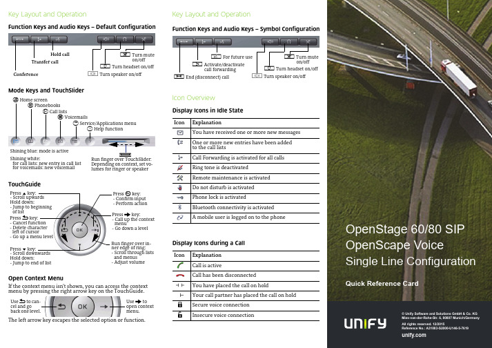
© Unify Software and Solutions GmbH & Co. KGMies-van-der-Rohe-Str. 6, 80807 Munich/GermanyAll rights reserved. 12/2015Reference No.: A31003-S2000-U146-5-7619Key Layout and OperationFunction Keys and Audio Keys – Default ConfigurationMode Keys and TouchSliderTouchGuideOpen Context MenuIf the context menu isn’t shown, you can access the contextmenu by pressing the right arrow key on the TouchGuide.The left arrow key escapes the selected option or function.Hold callTransfer callConferencep Turn muteon/offo Turn headset on/offn Turn speaker on/offt Home screenu Phonebooksw Call listsx Voicemailsv Service/Applications menuy Help functionRun finger over TouchSlider:Depending on context, set vo-lumes for ringer or speakerXShining blue: mode is activeShining white:for call lists: new entry in call listfor voicemails: new voicemailPress m key:- Scroll upwardsHold down:- Jump to beginningof listPress l key:- Scroll downwardsHold down:- Jump to end of listPress g key:- Call up the contextmenu- Go down a levelPress h key:- Cancel function- Delete characterleft of cursor- Go up a menu levelPress i key:- Confirm input- Perform actionRun finger over in-ner edge of ring:- Scroll through listsand menus- Adjust volumeUse g toopen contextmenu.Use h to can-cel and goback one level.Key Layout and OperationFunction Keys and Audio Keys – Symbol ConfigurationIcon OverviewDisplay Icons in Idle StateDisplay Icons during a CallIcon ExplanationYou have received one or more new messagesOne or more new entries have been addedto the call listsCall Forwarding is activated for all callsRing tone is deactivatedRemote maintenance is activatedDo not disturb is activatedPhone lock is activatedBluetooth connectivity is activatedA mobile user is logged on to the phoneIcon ExplanationCall is activeCall has been disconnectedYou have placed the call on holdYour call partner has placed the call on holdSecure voice connectionInsecure voice connectionq For future user Activate/deactivatecall forwardings End (disconnect) callp Turn muteon/offo Turn headset on/offn Turn speaker on/off{}OpenStage60/80SIPOpenScape VoiceSingle Line ConfigurationQuick Reference CardUsing your OpenStagePlace a Call•Lift handset, dial number and press i, or•dial number and lift handset, or•for handsfree call: dial number and press i.Answer a Call•Lift handset, or•for handsfree call: press n.End a Call•Hang up,or•to end a handsfree call: press n.Use the headset•Place a call: dial number and press i.•Answer or end a call: press o.Redial a Number1.Select "Redial" in the context menu and press i.2.Lift handset to use handset mode.Hold or Retrieve a Call•During a call press pre-programmed Hold key.•To retrieve a call: press pre-programmed Hold key.Make a Conference Call1.During a call with party A, press pre-programmed Conferencekey.2.Enter the phone number for party B and press i.3.Once connected with party B, press pre-programmed Confe-rence key.You are now connected in a conference with party A and B. Transfer a CallBlind transfer (no consultation):1.During the call with party A, select"Blind transfer" in the con-text menu and press i.2.Enter the phone number of party B and press i.Semi-attended transfer (transfer while ringing):1.During the call with party A, press pre-programmed Transferkey.2.Enter the phone number of party B and press i.3.When the phone starts to ring, select "Complete transfer"and press i.Attended transfer (with consultation):1.During the call with party A, press pre-programmed Transferkey.2.Enter the phone number of party B and press i.3.Announce the call to party B.4.Select "Complete Xfer" in the context menu and press ing your OpenStageProgramm Call Forwarding1.Press pre-programmed Call Forwarding Key.2.Select "Set a forwarding destiantion" and press i.3.Enter the destination number and press i.4.Select "Save&Exit" in the menu and press i.5.Press v to return to phone mode.Turn Call Forwarding on or off for All Calls•Press r for turning Call Forwarding on/off.Dial from the Call List1.Press w.2.The "Missed" tab will appear first, press w repeatedly for"Dialed", "Received", or "Forwarded" tabs.3.Select the desired phone number and press i.Activate Callback while calling1.Enter the destination phone number and press i.2.If there is no answer or the line is busy: select "Callback"from the context menu and press i.Deflect a Call while ringing1.Select "Deflect" from the context menu and press i.2.Enter a destination phone number and press i.Use Mute during a call•Press p for turning mute on or off.Switch to Speakerphone Mode during a Call•US mode:press n and hang up.•Default mode: hold down n until you hang up.Switch to Handset Mode during a Call•Lift handset.Save a Function to a Key1.Press and hold the desired programmable keyuntil a popup appears.2.Press i to confirm entering programming mode.3.Select "Normal" or "Shifted" and press i.4.Select desired function and press i.5.Define an appropriate key label and press i.6.In some cases: enter additional parameters and press i.7.Select "Save&Exit" in the context menu and press i.8.Press v to return to phone mode.List of Programmable Functions* only visible if provided by adminFunction ExplanationUnallocated Clears the keySelected dialing Dials a pre-defined numberRepeat dialing Calls the last dialed numberForward all calls Forwards all incoming callsForward no reply Forwards calls only if they are notansweredForward busy Forwards calls only when the line isbusyRinger off Switches the ringer off/onHold Places a call on holdAlternate Switches between two callsBlind transfer call Transfers a call without consultationTransfer call Transfers a call with consultationDeflect Deflects a call to another destinationShift Switches to the shifted key levelConference Places a conference callHeadset Answers a call using the headsetDo not disturb Switches the ringer off; callers hear thebusy signalGroup pickup Picks up a group callRepertory dial Dials pre-defined numbers and controlsequencesShow phone screen Toggles features hosted by OpenScapeVoiceMobility Login/Logoff for mobile usersDirected pickup Picks up another ringing phoneCallback Requests an automatic call back(busy/no answer)Cancel callbacks Cancels a callback requestConsultation Puts an active call on hold and providesa prompt for dialingDSS*Dials a pre-defined internal numberCall Waiting Notifies of a second incoming call whilein active callImmediate ring Ringing keyset line without delay(Executive/Assistant configuration)Preview Preview line details for shared linesAICS Zip tone*For headset operation only:auto answer and alert toneStart application Launches an application (short cut)Built in fwd Turns Call Forwarding on/off。
UniFi AP UAP LR 中文使用说明书
硬件安装 . . . . . . . . . . . . . . . . . . . . . . . . . . . . . . . . . . . . . . . . . . . . . . . . . . . . . . . . . . . . . . . . . . . . . . . . . . 3 软件安装 . . . . . . . . . . . . . . . . . . . . . . . . . . . . . . . . . . . . . . . . . . . . . . . . . . . . . . . . . . . . . . . . . . . . . . . . . . 5
章8:Guests(来宾)标签 . . . . . . . . . . . . . . . . . . . . . . . . . . . . . . . . . . . . . . . . . . . . . 27
章9:Offline Clients(离线客户端)标签 . . . . . . . . . . . . . . . . . . . . . . . . . . . . . . 29
添加Google Map™. . . . . . . . . . . . . . . . . . . . . . . . . . . . . . . . . . . . . . . . . . . . . . . . . . . . . 15
将无线接入点放到地图上. . . . . . . . . . . . . . . . . . . . . . . . . . . . . . . . . . . . . . . . . . . . . . . . . . . . . . . . . 17 设置地图比例尺 . . . . . . . . . . . . . . . . . . . . . . . . . . . . . . . . . . . . . . . . . . . . . . . . . . . . . . . . . . . . . . . . . . 19
联科通网络技术有限公司150M入墙式AP说明书
版权声明是深圳市联科通网络技术有限公司注册商标。
文中提及的其它商标或商品名称均是深圳市联科通网络技术有限公司的商标或注册商标。
本产品的所有组件,包括硬件和软件,其版权属深圳市联科通网络技术有限公司所有,在未经过深圳市联科通网络技术有限公司许可的情况下,不得任意拷贝、抄袭、仿制或翻译成其它语言。
本手册中的所有图片和产品参数仅供参考,随着软件或硬件的升级会略有差异,如有变更,恕不另行通知,如需了解更多产品信息,请登录我们公司网站:目录版权声明 (2)目录 (3)第I部分产品简介 (5)1包装清单 (5)2面板指示灯及接口说明 (5)3产品规格 (7)第II部分快速上网设置 (8)1物理连接 (8)2有线连接电脑配置 (8)2.1 Win 7系统电脑设置 (8)2.2 XP 系统电脑设置 (13)3无线连接电脑配置 (16)3.1 Win7 系统无线连接 (16)3.2 XP 系统无线连接 (19)第III部分高级设置 (23)1登录 (23)2系统状态 (24)2.1 系统状态 (24)2.2 无线状态 (25)2.3 AP报文统计 (26)2.4 无线客户端 (27)3LAN口设置 (28)4DHCP服务器 (28)4.1 DHCP服务器 (28)4.2 DHCP连接列表 (29)5无线设置 (30)5.1 基本设置 (30)5.2 射频设置 (33)5.3 高级设置 (35)5.4 访问控制 (36)6SNMP设置 (37)7系统工具 (38)7.1 设备维护 (38)7.2 时间管理 (39)7.3 日志查看 (40)7.4 配置管理 (42)7.5 用户名与密码 (43)7.6 诊断工具 (44)附录一 TCP/IP地址设置方法 (46)附录二有毒有害物质申明 (50)第I部分产品简介W15AP是IP-COM专为酒店设计的Wi-Fi接入点,为用户提供便捷的WLAN服务。
标准的86盒安装,借助现有的建筑架构,无需耗费较多时间及成本即可轻松完成无线网络组建。
UNIFAP 移动设备(iPad、iPhone、iPod Touch)Webmail手册说明书
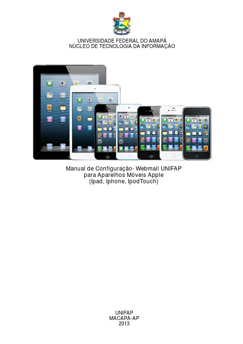
Manual de Configuração- Webmail UNIFAPpara Aparelhos Móveis Apple(Ipad, Iphone, )IpodTouch UNIVERSIDADE FEDERAL DO AMAPÁNÚCLEO DE TECNOLOGIA DA INFORMAÇÃOUNIFAPMACAPÁ-APS U MÁR I O1 Tela Inicial (2)2 Tela de Ajustes (3)3 Adicionando a conta de email (4)4 Tela Outra (5)5 Tela Cadastro (6)6 Tela Nova Conta (7)7 Caso apareça alguma mensagem (8)8 Acessando o Email (9)1- TELA INICIALEsta é a tela de menu do aparelho móvel, para adicionar a conta de email da Unifap no seu aparelho primeiramente aperte o botão Ajuste da tela de menu, como o exemplo destacado na imagem acima.2- TELA DE AJUSTESAgora aperte em Mail, Contatos, Calendário do menu de ajuste, localizado no lado esquerdo. Em seguida aperte Adicionar conta... localizado nos campos de Contas.3- ADICIONANDO A CONTA DE EMAILAgora no menu de opções da tela Adicionar conta...aperte em Outra.4- TELA OUTRANa tela Outra aperte em Conta do Mail.5- TELA DE CADASTROEsta é a tela de Cadastro do usuário, observe o exemplo acima, e preencha as informações corretamente. Aperte em Seguinte para prosseguir com a operação ou em Cancelar para interromper.Com o botão IMAP ativado, preencha os campos conforme o solicitado, uma atenção especialao campo Nome do Host nele deve ser digitado: “atlantico.unifap.br”. prosseguir com a operação ou em Cancelar para interromper.Aperte em Seguinte para6- TELA NOVA CONTA7- CASO AP AREÇA ALGUMA MENSAGEMCaso apareça a mensagem “Preferences não pode verificar a identidade do “atlantico.unifap.br.Deseja continuar mesmo assim?”, aperte em Continuar.8- ACESSANDO O EMAILPor fim, voltando a tela inicial do aparelho móvel, aperte em Mail, para acessar a conta de email cadastrada.。
UniFi全家桶的入门设置教程(UCKUSGUSWAP)
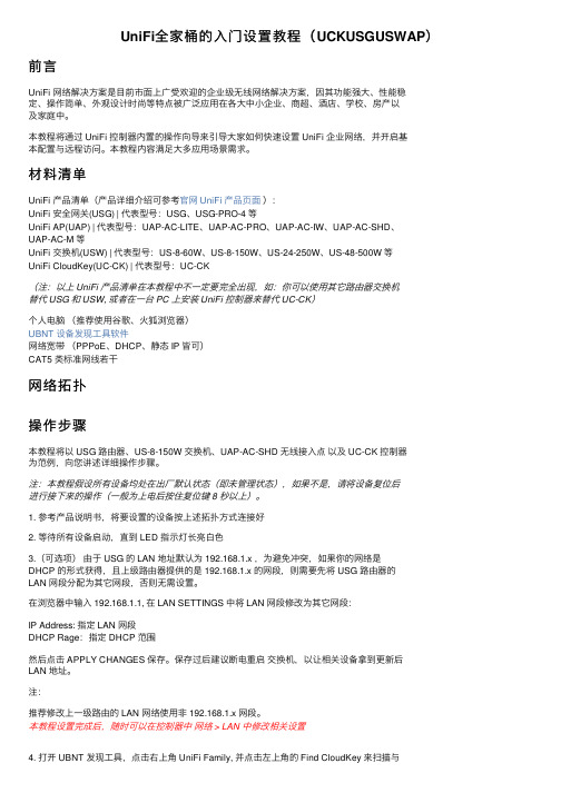
UniFi全家桶的⼊门设置教程(UCKUSGUSWAP)前⾔UniFi ⽹络解决⽅案是⽬前市⾯上⼴受欢迎的企业级⽆线⽹络解决⽅案,因其功能强⼤、性能稳定、操作简单、外观设计时尚等特点被⼴泛应⽤在各⼤中⼩企业、商超、酒店、学校、房产以及家庭中。
本教程将通过 UniFi 控制器内置的操作向导来引导⼤家如何快速设置 UniFi 企业⽹络,并开启基本配置与远程访问。
本教程内容满⾜⼤多应⽤场景需求。
材料清单UniFi 产品清单(产品详细介绍可参考官⽹ UniFi 产品页⾯):UniFi 安全⽹关(USG) | 代表型号:USG、USG-PRO-4 等UniFi AP(UAP) | 代表型号:UAP-AC-LITE、UAP-AC-PRO、UAP-AC-IW、UAP-AC-SHD、UAP-AC-M 等UniFi 交换机(USW) | 代表型号:US-8-60W、US-8-150W、US-24-250W、US-48-500W 等UniFi CloudKey(UC-CK) | 代表型号:UC-CK(注:以上 UniFi 产品清单在本教程中不⼀定要完全出现,如:你可以使⽤其它路由器交换机替代 USG 和 USW, 或者在⼀台 PC 上安装 UniFi 控制器来替代 UC-CK)个⼈电脑(推荐使⽤⾕歌、⽕狐浏览器)UBNT 设备发现⼯具软件⽹络宽带(PPPoE、DHCP、静态 IP 皆可)CAT5 类标准⽹线若⼲⽹络拓扑操作步骤本教程将以 USG 路由器、US-8-150W 交换机、UAP-AC-SHD ⽆线接⼊点以及 UC-CK 控制器为范例,向您讲述详细操作步骤。
注:本教程假设所有设备均处在出⼚默认状态(即未管理状态),如果不是,请将设备复位后进⾏接下来的操作(⼀般为上电后按住复位键 8 秒以上)。
1. 参考产品说明书,将要设置的设备按上述拓扑⽅式连接好2. 等待所有设备启动,直到 LED 指⽰灯长亮⽩⾊3.(可选项)由于 USG 的 LAN 地址默认为 192.168.1.x ,为避免冲突,如果你的⽹络是DHCP 的形式获得,且上级路由器提供的是 192.168.1.x 的⽹段,则需要先将 USG 路由器的LAN ⽹段分配为其它⽹段,否则⽆需设置。
UnitClien统一客户端使用说明书V
XX市微度数字统一客户端使用说明书XX市微度数字技术XX(技术部)SHENZHEN MICRODO DIGITAL TECHNOLOGY CO.,LTD2009.05目录第1章.简介21.1欢迎使用统一客户端21.2系统要求21.3系统功能模块31.4软件优点3第2章.客户端的安装与卸载32.1客户端的安装32.2客户端的卸载8第3章.客户端操作指南113.1登录系统113.2设备的添加113.2.1 新建设备组123.2.2 修改设备组名123.2.3 手动增加设备123.2.4 自动搜索设备133.2.5 自动增加设备143.3视频浏览143.3.1 视频连接、播放143.3.2 视频窗口位置的对调153.3.3 视频浏览窗口缩放153.3.4 视频流选择153.3.5 视频播放停止153.3.6 实时拍照163.3.7 反向音频163.3.8 开启音频163.3.9 音量调节163.3.10 分窗显示163.3.11 告警实时视频163.3.12 云台控制163.4录像回放173.4.1 设备的选择173.4.2 本地录像搜索173.4.3 前端录像搜索173.4.4 查看文件173.4.5 播放录像文件173.4.6 删除录像文件173.5告警信息173.5.1 设备的选择173.5.2 告警信息检索183.5.3 查看告警信息183.6录像设置183.6.1 策略配置18录像参数配置183.7告警联动193.7.1 设备的选择193.7.2 告警联动参数设置193.8用户信息203.8.1 用户组新增、修改、删除20 3.8.2 角色的添加、修改、删除20 3.9远程配置213.9.1 设备的选择213.9.2 远程配置213.10远程维护22设备的选择223.10.2 系统升级223.10.3 配置上传、下载223.10.4 其它维护操作223.10.5 SD卡管理233.11日志查询233.11.1 用户日志查询233.11.2 远程日志查询233.12帮助信息23第1章.简介微度数字视频统一客户端(Unit Client)是集视频监控、管理、控制的统一客户端,为您提供便捷的视频监控享受。
UniFi+AP的规格参数

企业级 WiFi 系统
型号: UAP、UAP-LR、UAP-PRO、UAP-AC UAP-Outdoor、UAP-Outdoor5
统一的管理系统,无论室内AP还是室外AP,均可无限扩展
突破性速度,最高可达1300 Mbps (802.11ac)
直观的 UniFi Controller 软件
热点管理 – 定制和内置计费选项
直观的UniFi Controller 软件 通过直观且简单易学的UniFi Controller用户界面,轻松安装、配置和管理所有UniFi AP。
可扩展 扩展性没有限制。根据需要组建或大或小的无线 网络。即使从单个包(或升级到三个包)扩展到数千个 包,仍保持单一的、统一的管理系统。
讲堂 UAP-PRO
无线扩展 利用无线下行。一个有线 UniFi AP 上行支持最多四个无线下行,允许以其默认状态应用设备并实时更改网络拓 朴。
管理热点和控制计费 使用热点管理器来定制门户登录页和使用常用信用卡对客户收费。或者,使用热点管理器设置基于凭 证的身份验证系统进行凭证创建、来宾管理和退款。
/unifi 8
包含: • 墙壁固定装置和天花板固定装置电源适配器套件 • 以太网供电电源适配器 • UniFi Controller 软件安装光盘
室内型号比较图
2.4 GHz 速度*
UniFi AP (UAP)
300 Mbps
5 GHz 速度*
范围* 122 m (12,192.00 cm)
辅助以太网端口
Gigabit 千兆以太网
3个或多个 UAP-AC
3个或多个 UAP/UAP-LR/UAP-PRO
UAP-AC UAP/UAP-LR/UAP-PRO
unifi使用手册
unifi使用手册全文共四篇示例,供读者参考第一篇示例:Unifi使用手册Unifi是Ubiquiti Networks公司推出的一款用于管理无线网络设备的软件,它可以帮助用户简单方便地管理多个Wi-Fi接入点,无线路由器等设备。
在网络连接和管理方面提供了更强大的支持和功能。
本手册将向您介绍如何使用Unifi来管理您的网络设备。
一、安装Unifi软件首先您需要从Ubiquiti Networks的官方网站下载Unifi软件,选择适合您操作系统的版本进行下载。
安装完成后,打开软件并创建一个账号,登录后将会提示您是否要设置一个新的Unifi控制器,选择是并按照向导进行操作即可。
二、添加设备在Unifi软件中,您可以添加各种设备进行管理,比如无线接入点,无线路由器等。
点击左侧菜单栏的“设备”选项,然后点击右上角的“添加设备”按钮,输入您要添加设备的地址和登录凭据,系统会自动识别设备并添加到您的控制器中。
三、配置网络配置网络是使用Unifi的重要一步,您可以为不同的设备设置不同的网络配置,比如SSID名称,密码,频段等。
在Unifi软件中,选择“网络”选项,然后点击“新建网络”按钮,根据提示填写相关信息即可。
四、监控设备Unifi软件提供了丰富的监控功能,您可以实时查看设备的运行状态,包括在线状态,网络流量等。
点击左侧菜单栏的“设备”选项,选择要查看的设备,然后就可以看到相关的监控信息了。
五、配置热点六、固件升级Unifi软件会自动检测设备的固件版本,并提示您是否需要升级。
在“设备”选项中,选择您要升级的设备,然后点击“升级固件”按钮,根据提示进行操作即可。
七、日志记录八、备份与恢复为了保证数据的安全,建议您定期备份Unifi的配置文件。
在Unifi软件中,选择“设置”选项,然后点击“备份”按钮,选择要备份的配置文件位置,系统会自动为您创建一个备份文件。
如果需要恢复数据,选择“还原”按钮即可。
九、远程管理如果您需要在不同地点管理网络设备,可以使用Unifi的远程管理功能。
UNIFY门户用户手册说明书
User’s ManualforUNIFY PORTALDeveloped byNational Crime Records BureauNew DelhiT ABLE OF C ONTENTS1INTRODUCTION (2)2UNIFY WEB APPLICATION (3)3GETTING STARTED (4)4HOME/LANDING PAGE (5)5CREATE ACCOUNT (6)6LOGIN (8)7IDENTIFY RECOVERED PERSON/DEAD BODY/MISSING PERSON (9)8SUCCESS STORIES (12)9FORGOT/RESET PASSWORD (13)10CHANGE PASSWORD (15)1INTRODUCTIONVisionNCRB keeps on exploring technologies to reduce manual and redundant efforts being done in policing. As part of such exploration, NCRB has come with an idea to have an Automated Facial Recognition System (AFRS), based on Image based search/comparison techniques.NCRB has developed, an AI based, Image searching application (namely Unify), which compares the photos of probed/searched with CCTNS national database (missing person/found- person/dead-bodies/accused) and returns the probable matches for manual comparison. Features:Unify App has the following featuresAutomated facial recognition system, developed using AI/ML technologies.AI / Machine Learning based model to compare facial featuresIdentifies Person of Interest (PoI) (Dead-bodies/Suspects/Unknown Found/Missing Persons) against photos available in CCTNS Database.Eases back tracking of PoI, incase PoI was in contact with police.Accessible to Police over Internet through ‘.in’Secure Application, vetted by CERT-In empanelled agencyReturns Best 3 Matches from the national CCTNS Database2UNIFY WEB APPLICATIONUsing UNIFY Web Application, user can upload photos of Person of Interest (suspect/found person/dead-body) and can search them in CCTNS National database; in turn, system would return the most probable images of persons along with case/complaint information. In case results match with the probed PoI, then Police officers may compare the images and other particulars from CCTNS search application using case/compliant number returned by UNIFY and act accordingly. The entire operation can be done in real time. Thus would reduce the efforts needed, in case the person has come in contact with police.Following modules are present in the application:Create AccountLoginDashboardSearch Identify Recovered Person/Dead BodySuccess Stories3GETTING STARTEDOpen any internet browser (i.e. Internet Explorer, Firefox, etc.)Enter URL .in/. in browser address barClick on UNIFY-WEBAPP to IDENTIFYYou will be redirected to UNIFY Home pageOr Enter URL https://164.100.44.122/api/home directly in browser address bar4HOME/LANDING PAGEUnify Home Page facilitates users to Login and Create new account.5 CREATE ACCOUNTNew users may create an account themselves using option “Create Account”Choose User Name, Password, Re-Password and enter First Name, Last Name andE-Mail(Only Govt. email IDs with domain name gov.in or nic.in can be used) Click on Create Account.An email containing activation link of account will be sent to your email Click on the Activation link shared through email, to activate your accountClick on “Yes” button, if prompted by browser.E-mail Activation Link6 LOGINClick on Login button.Enter Username, Password and Captcha(given in image) Click on Login button.7IDENTIFY RECOVERED PERSON/DEAD BODY/MISSING PERSONThis page used to identify POI by uploading PoI’s photoIdentify Recovered Person/Dead Body/Missing Person page displays option to upload photo to identify POI.Click “Choose file” buttonSelect the photo of the person to identifyClick on person type to filter the search results by person type (By default is “ALL”) i.e. Missing Person, Unidentified person, Unidentified Dead body, Others etc.To further narrow don the search Click on Calendar control to choose a date after which the search is to be executedClick on “IDENTIFY” buttonMatching results will be displayed. User may select corresponding feedback radio button, in case of a correct match.Click on “Submit” button to save your feedbackClick OpenChoose Person Type from DropdownScreenshot of Accused Person Search resultScreenshot of Missing Person SearchScreenshot of Dead Person Search8SUCCESS STORIESThis page displays, feedback submitted by user.9FORGOT/RESET PASSWORDGo to Login Page (URL- https://164.100.44.122/api/login/)Click on Forgot password linkEnter registered email address associated your accountOn clicking the submit button User will receive a link to reset password in his registered email-id. Click on the link received via emailEnter New password and its confirmationFinally click on “SUBMIT” button to save passwordOn success you will be redirected to reset password completion pageENTER NEW PASSWORDENTER NEW PASSWORDENTER OLD PASSWORD10 CHANGE PASSWORDLogin to the portalClick on Menu(Welcome user) Choose Change Password Enter Old/Current password Enter New password Re-enter new passwordSelect “SAVE CHANGES” button to successfully change password.。
Un-link 最新AC控制器使用手册.
目录目录 .......................................................................................................................................... 2第一章详细配置指南简介 .....................................................................................................4 1.1本说明约定 .................................................................................................................4 1.2本说明章节安排 .........................................................................................................4第二章产品概述 ....................................................................................................................5 2.1 产品简介 .....................................................................................................................5 2.2 主要特性 .....................................................................................................................5第三章硬件描述 ....................................................................................................................6 3.1 面板布置 .....................................................................................................................6 3.2安装环境 .....................................................................................................................6第四章快速安装指南 .............................................................................................................7 4.1 硬件连接 .....................................................................................................................7 4.2 如何登陆 AC 控制器 ...................................................................................................7 4.3网络设置 .....................................................................................................................9 4.3.1子端口设置 ..............................................................................................................9 4.3.2瘦AP 端口设定 (10)4.3.3DHCP 配置 (10)4.3.4 链路检测 (11)4.4 RF配置 (12)4.4.1 AP默认配置 (12)4.4.2瘦 AP 配置模板 (13)4.4.3 瘦 AP 配置模板应用 (14)4.5 接入控制 (14)4.6 高级应用 (15)4.7 管理 (16)4.7.1 更改密码 (16)4.7.2 AC升级 (17)4.7.3 AP镜像上传 .........................................................................................................17 4.7.4 备份 /恢复设定 .....................................................................................................18 4.8 信息 ...........................................................................................................................19 4.8.1 AP资产管理 ..........................................................................................................19 4.8.2 瘦 AP 在线列表 ......................................................................................................19 4.8.3 无线终端列表 .. (21)第一章详细配置指南简介本文档旨在帮助您正确使用 AC 控制器的功能,内容包括 AC 控制器的性能特征以及所有功能的详细说明,若要使用路由器中的其他应用方面的功能,可以参考本文档相关部分内容。
unifi poe 供电电源 用法
unifi poe 供电电源用法Unifi PoE(Power over Ethernet)供电电源是一种先进的供电技术,可将电力和数据信号同时传输到网络设备。
它的使用广泛,是许多企业和组织中网络设备供电的首选技术。
本文将详细介绍Unifi PoE供电电源的用法以及它在不同领域的应用。
首先,让我们先了解一下什么是PoE供电技术。
PoE技术可以将电力通过以太网电缆传递给网络设备,而无需使用额外的电缆或电源适配器。
这种技术通过转换器将电力从电源发送到电缆中的数据线对上,然后在接收器端将电力从数据线对中提取出来并为设备供电。
由于PoE技术的灵活性和便利性,它已被广泛应用于各种网络设备,包括无线接入点、网络摄像头、IP电话等。
Unifi PoE供电电源是由Ubiquiti Networks公司开发的一种高效的PoE供电解决方案。
它使用一种被称为802.3af或802.3at标准的PoE技术,可以为网络设备提供多达30瓦的供电能力。
Unifi PoE供电电源还具有热插拔功能,意味着您可以在设备运行时插拔电源,而无需关闭设备或重新启动。
这使得使用Unifi PoE供电电源非常方便和可靠。
Unifi PoE供电电源的用法非常简单。
首先,您需要确保网络交换机或电源注入模块支持PoE技术。
然后,您可以使用带有PoE端口的Unifi PoE供电设备连接到交换机或电源注入模块。
一旦连接成功,Unifi PoE供电设备就可以从交换机或电源注入模块接收电力,并将其传输到连接的网络设备。
这样,您就可以同时供电和连接您的网络设备,而无需使用额外的电源适配器或电缆。
Unifi PoE供电电源的用途非常广泛。
在企业网络中,它被广泛应用于无线接入点的供电,以确保无线网络的稳定运行。
通过使用Unifi PoE供电电源,无线接入点可以直接从网络交换机或电源注入模块接收供电,从而消除了在各个区域布置电源适配器的麻烦。
这不仅提高了网络可靠性,还降低了部署和维护成本。
瘦AP三层隧道使用说明
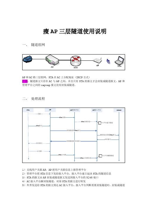
瘦AP三层隧道使用说明一、隧道组网AP和AC跨三层组网,STA在AC上分配地址(DHCP方式)注意:隧道报文只存在AC与AP之间,并且只有STA的报文才会封装成隧道报文,AP和管理平台之间的capwap报文没有封装成隧道。
二、处理流程1)无线用户关联AP,AP把用户关联信息上报管理平台2)管理平台把STA信息下发给接入平台,接入平台建立起该STA的隧道信息3)STA的报文由AP封装成隧道报文发送到接入平台的5248端口4)AC接入平台解封装隧道,对原STA的报文进行转发5)外界发送给STA的报文到达AC接入平台,接入平台判断需要封装隧道时,封装成隧道报文发送给AP6)AP把隧道报文解封装,发送给STALiuzhijian!@#221.131.176.156三、隧道配置管理平台配置1. 登录web管理界面,打开页面【基本配置】【隧道配置】,进行如下配置模式开关:开开启隧道模式关闭关闭隧道模式注意:目前隧道配置命令只在AP加入时下发给AP,中途修改隧道配置不会发消息给在线的AP接入平台IP:AP发送的隧道报文的目的IP,接入平台接口的任意一个地址均可,只要能与AP互通端口: AP发送的隧道报文的目的端口,固定为5248模式选择:固定为UDP隧道模式:选择1-MACBridge2. 配置文件登录AC管理平台,修改access.conf文件# vi /icac/conf/access.conf1 10.1.1.4 4603格式:编号 IP地址端口,各字段以空格分隔,描述:编号为数字1,2.. ,IP地址为接入平台的地址,端口固定为4603。
说明:一个编号表示一条记录,如果一个管理平台连接多个接入平台,需配置多条,多条之间没有顺序要求修改后需重启accomm才能生效修改forward.conf文件# vi /icac/conf/forward.conf10.1.1.4 4603 127.0.0.1 4603格式:IP地址端口 IP地址端口,各字段以空格分隔,描述:配置为接入平台的IP地址,端口固定为4603说明:只有一条记录,目前最多只支持2个接入平台,只有一个接入平台时,另一个IP地址可配置127.0.0.1 ,修改后需重启accomm才能生效接入平台配置接入平台跟隧道相关的命令有以下几条:system mode模式:Config模式语法:[no] system mode fat-ap | fit-ap描述:必选命令。
UniFi AP Datasheet 中文版

集中化、高拓展性的企业WiFi管理平台UniFi系统是一套企业无线接入整体解决方案,在具备简单部署和管理特性的同时,拥有极高的可扩展性。
所有的UniFi AP均采用圆形吸顶设计,可在无辅助材料的情况下安装至天花或墙体上。
UniFi AP所采用的POE(以太网供电)方式,将数据与电源共缆传输,大大简化了设计与施工难度。
UniFi系统包含了UniFi Controller控制软件。
该软件替代了传统AC(无线控制器)复杂繁琐的管理方式,可安装于任何一台PC或Mac 设备上,通过标准的Web浏览器访问。
UniFi Controller控制软件的即时配置方式,无需专业化的操作培训即可使用。
并提供实时的设备状态检测、地图加载、流量图表分析等直观数据。
UniFi AP-Mini (UAP-Mini)802.11n UniFi AP, 基础单元。
具备150 Mbps的链路速度100米的覆盖距离。
UAP-Mini 套件包括:●墙壁和天花板安装转接器套件●以太网电源适配器●UniFi Controller控制软件安装光盘功能设计独特的LED环形灯设计,为网络管理者提供了简单醒目的设备状态指示。
强大的硬件UniFi AP 设备使用了标准的802.11技术(b/g/n 标准) ,并提供300 Mbps 链路速度,150 ~ 200米覆盖范围。
可视化的UniFi Controller控制软件直观的安装、配置、管理UniFi AP设备,无需专业化的操作培训即可使用。
扩展无限制的扩展能力。
依据无线网络的覆盖密度,轻松调整网络布局,且保证了集中化管理的要求(例如:统一SSID,统一认证或计费方式,统一登陆密码等)。
UniFi AP (UAP)802.11n MIMO UniFi AP, 标准单元。
具备300 Mbps的链路速度150米的覆盖距离。
UAP 套件包括:●墙壁和天花板安装转接器套件●以太网电源适配器●UniFi Controller控制软件安装光盘简易安装圆形壁挂和天花板瓷砖贴装设计。
Unified Brands 产品操作手册说明书
This manual provides information for:OPERATOR MANUAL IMPORTANT INFORMATION, KEEP FOR OPERATORPART NUMBER 121006, REV. F (11/11)THIS MANUAL MUST BE RETAINED FOR FUTURE REFERENCE.READ, UNDERSTAND AND FOLLOW THE INSTRUCTIONS ANDWARNINGS CONTAINED IN THIS MANUAL.FOR YOUR SAFETY Do not store or use gasoline or other flammable vapors and liquids in the vicinity of this or any other appliance.WARNING Improper installation,adjustment, alteration, service or maintenancecan cause property damage, injury ordeath. Read the installation, operating and maintenance instructions thoroughly before installing or servicing this equipment.NOTIFY CARRIER OF DAMAGE AT ONCEIt is the responsibility of the consignee to inspect the container upon receipt ofsame and to determine the possibility of any damage, including concealed dam-age. Unified Brands suggests that if you are suspicious of damage to make anotation on the delivery receipt. It will be the responsibility of the consignee to filea claim with the carrier. We recommend that you do so at once.Manufacture Service/Questions 888-994-7636.Information contained in this document is known to be current and accurate at the time of printing/creation. Unified Brands recommends referencing our product line websites,, for the most updated product information and specifications.MODELS TD/3 &TDA/1 DomesticSTEAM JACKETED KETTLE· Stainless Steel· Table Top Mounted· Direct Steam Heated· TiltingCAUTION: BE SURE ALL OPERATORS READ, UNDERSTAND AND FOLLOW THE OPERATINGINSTRUCTIONS, CAUTIONS, AND SAFETY INSTRUCTIONS CONTAINED IN THIS MANUAL. WARNING: THIS UNIT IS INTENDED FOR USE IN THE COMMERCIAL HEATING, COOKING AND HOLDING OF WATER AND FOOD PRODUCTS, PER THE INSTRUCTIONS CONTAINED IN THIS MANUAL. ANYOTHER USE COULD RESULT IN SERIOUS PERSONAL INJURY OR DAMAGE TO THE EQUIPMENTAND WILL VOID WARRANTY.WARNING: KETTLES MUST BE INSTALLED BY PERSONNEL QUALIFIED TO WORK WITH STEAM PLUMBING.IMPROPER INSTALLATION CAN RESULT IN INJURY TO PERSONNEL AND/OR DAMAGE TOEQUIPMENT.WARNING: AVOID ANY EXPOSURE TO ESCAPING STEAM. STEAM CAN CAUSE SEVERE BURNS. WARNING: TAKE EXTREME CARE TO KEEP HOT CONTENTS FROM SPILLING OR SPLASHING ON ANYONE.DO NOT STAND DIRECTLY IN FRONT OF KETTLE BODIES WHEN THEY ARE BEING TILTED. WARNING: AVOID ALL DIRECT CONTACT WITH HOT EQUIPMENT SURFACES. DIRECT SKIN CONTACT COULD RESULT IN SEVERE BURNS.WARNING: AVOID ALL DIRECT CONTACT WITH HOT FOOD OR WATER IN KETTLES. DIRECT CONTACT COULD RESULT IN SEVERE BURNS.CAUTION: DO NOT OVER FILL THE KETTLE WHEN COOKING, HOLDING OR CLEANING. KEEP LIQUIDS AT A MINIMUM OF 2-3” (5-8 CM) BELOW THE KETTLE BODY RIM TO ALLOW CLEARANCE FORSTIRRING, BOILING AND SAFE PRODUCT TRANSFER.WARNING: TAKE SPECIAL CARE TO AVOID CONTACT WITH HOT KETTLE BODY OR HOT PRODUCT WHEN ADDING INGREDIENTS, STIRRING OR TRANSFERRING PRODUCT TO ANOTHER CONTAINER. WARNING: WHEN TILTING KETTLE FOR PRODUCT TRANSFER:1) WEAR PROTECTIVE OVEN MITT AND PROTECTIVE APRON.2) USE CONTAINER DEEP ENOUGH TO CONTAIN AND MINIMIZE PRODUCT SPLASHING.3) PLACE CONTAINER ON STABLE, FLAT SURFACE, AS CLOSE TO KETTLE AS POSSIBLE.4) STAND TO LEFT OR RIGHT SIDE OF KETTLE (DEPENDING ON TILTING HANDLE PLACEMENT)WHILE POURING. DO NOT STAND DIRECTLY IN POUR PATH OF HOT CONTENTS.5) POUR SLOWLY, MAINTAIN CONTROL OF KETTLE BODY HANDLE AT ALL TIMES, ANDRETURN KETTLE BODY TO UPRIGHT POSITION AFTER CONTAINER IS FILLED OR TRANSFER ISCOMPLETE.6) DO NOT OVER FILL CONTAINER. AVOID DIRECT SKIN CONTACT WITH HOT CONTAINER ANDITS CONTENTS.CAUTION: KEEP FLOORS IN FRONT OF KETTLE WORK AREA CLEAN AND DRY. IF SPILLS OCCUR, CLEAN IMMEDIATELY TO AVOID SLIPS OR FALLS.WARNING: FAILURE TO CHECK SAFETY VALVE OPERATION PERIODICALLY COULD RESULT IN PERSONAL INJURY AND/OR DAMAGE TO EQUIPMENT.WARNING: WHEN TESTING, AVOID ANY EXPOSURE TO THE STEAM BLOWING OUT OF THE SAFETY VALVE.DIRECT CONTACT COULD RESULT IN SEVERE BURNS.2 OM-TDCAUTION: MOST CLEANERS ARE HARMFUL TO THE SKIN, EYES, MUCOUS MEMBRANES AND CLOTHING.PRECAUTIONS SHOULD BE TAKEN. WEAR RUBBER GLOVES, GOGGLES OR FACE SHIELD ANDPROTECTIVE CLOTHING. CAREFULLY READ THE WARNINGS AND FOLLOW THE DIRECTIONS ONTHE LABEL OF THE CLEANER TO BE USED.CAUTION: USE OF ANY REPLACEMENT PARTS OTHER THAN THOSE SUPPLIED BY AUTHORIZED DISTRIBUTORS CAN CAUSE OPERATOR INJURY AND DAMAGE TO THE EQUIPMENT, AND WILLVOID ALL WARRANTIES.WARNING: SERVICE PERFORMED BY OTHER THAN FACTORY AUTHORIZED PERSONNEL WILL VOID WARRANTIES.OM-TD 3Important Operator Warnings .....................................................page 2-3References..................................................................................... page 4Equipment Description.................................................................. page 5Inspection and Unpacking ............................................................ page 6Installation ..................................................................................... page 7Initial Start-Up................................................................................ page 8Operation ................................................................................... p age 9-10Sequence of Operation ................................................................ page 11Cleaning........................................................................................ page 12Maintenance................................................................................. page 13Troubleshooting............................................................................ page 14Part Lists/Diagram .................................................................. page 15-17Service Log ............................................................................ page 18-19KLENZADE SALES CENTER ECOLAB. Inc.370 WabashaSt. Paul, Minnesota 55102800/352-5326 or 612/293-2233NATIONAL SANITATION FOUNDATION3475 Plymouth Rd.Ann Arbor, Michigan 48106ZEP MANUFACTURING CO.1310-T Seaboard Industrial Blvd.Atlanta, Georgia 303184 OM-TDOM-TD 5The TDC/3 and TDA/1 are tilting, table-top kettles with direct steam-heated jackets. The one-piece stainless steel body on each includes a butterfly shaped pouring lip. The kettles have a 180 emery grit interior finish and a bright semi-deluxe exterior finish.Every unit requires a remote steam source. The steam supply is controlled by an inlet valve, and enters the jacket through one support and rotary joint. Condensate leaves the jacket through the other rotary joint and support. Standard units are ASME shop inspected, stamped, and registered with the National Board. These kettles operate efficiently at pressures above five PSI. A safety valve, strainer, steam trap, and check valve are all required for installation, and may be ordered as optional equipment.Optional features and equipment include:• Higher maximum pressure • Bracket inserts • Lift-off covers • Kettle brush kit • Open leg mounting table mounting • Steam trap assembly The TDC/3 kettle has a jacket rated for working pressures up to 55 PSI. The kettle body incorporates a reinforced rim. Two tubular steel supports support the swivel on which the kettle tilts. A support leg projects from the bottom rear of the kettle.The design makes it easy for one person to tilt the kettle with the tilting handle, even when the kettle is full.The TDA/1 kettle incorporates a reinforced rim and a jacket rated for working pressures up to 50 PSI. Two chrome-plated arms support the trunnions on which the kettle tilts. The arm that also serves as the steam inlet has an integral steam control valve.TDC/3TDA/1The kettle will arrive completely assembled and wrapped in protective plastic,strapped and bolted on a skid, enclosed in a cardboard crate. Immediately on receiptremove the box and plastic wrap, and inspect the unit for damage. Report anydamage or an incorrect shipment to the delivery agent.Write down the model number, serial number and installation date, and keep thisinformation for future reference. Space for these entries is provided at the top of theService Log in the back of this manual.When installation is to begin, cut the straps holding the unit on the skid. Lift the unitstraight up off of the skid.6 OM-TDOM-TD 71.Installation under a ventilation hood is recommended. Consult local codes.2. Install and anchor the kettle on a level and rigid surface. Recommended mounting surface is 16 gauge (.060” thick) top with a lower reinforcement of C4 structural channel. NOTE: Failure to install the kettle per above recommendation may cause the steam piping to flex and leak, reduce seal life and will void warranty. (see figure at left)3. If the steam supply pressure is greater than the maximum working pressure stamped on the nameplate, you must install a pressure reducing valve in the steam supply line near the kettle.4. Connect the steam supply line to the steam inlet fitting. Include a steam control valve and an appropriate safety valve. To obtain the full heating capability of the kettle, the steam supply line must be as large as the steam inlet fitting.5. The safety valve must be preset to relieve jacket pressure that exceeds its rated limit. Do not try to adjust the valve setting, and do not allow the valve outlet or lever to be blocked.6. Connect the kettle condensate return line to the boiler return line, or to a drain. A suitable steam trap, strainer, and check valve must be installed. (See recom-mended piping diagram, below). A condensate return pump may be required.7.Any mechanical change must be approved by the Service Department.Standing Piping The inlet valve for TDC models may be located anywhere on the cabinet top or face but not through the face casting. The illustrated sleeve is designed to simplify valve installation by allowing the valve to shift off center by 1/4”, if necessary. This should be enough to allow for thread take-up and misalignment.*Accessories available as options. Piping is to be supplied by the installer.RIGID MOUNTING SURFACENow that the kettle has been installed, you should test it to ensure that it is operatingcorrectly.1. Remove all literature and packing materials from inside and outside of the unit.2. Pour a small amount of water into the kettle.3. Open the steam inlet valve.4. When the water begins to boil, inspect all of the fittings to ensure that there areno leaks.5. Check the safety valve by lifting its lever far enough to let steam escape. Thenlet it snap back into place to reset the valve so that it will not leak.6. Shut down the unit by closing the steam inlet valve.7. Operate the tilting mechanism to confirm that this feature functions through thewhole range of normal operation.If the unit functions as described above, it is ready for use. If the unit does not functionas intended, contact your local Certified Service Agency.8 OM-TDOM-TD 9To heat the kettle, open the steam inlet valve. Adjusting the valve allows you to control the heating rate. Opening the valve more allows steam to flow into the jacket faster, and heats the product faster.The kettle operates efficiently at pressures from five PSI to the maximum working pressure for which the kettle was designed. The maximum pressure is stamped on the kettle nameplate.1. Tilting To transfer product or empty the kettle: the kettle is designed and manufac-tured to be tilted in a controlled manner. Grasp the insulated plastic ball firmly. Maintain a firm grip on handle when tilting, while keeping the kettle body in a tilted position and then SLOWLY returning the kettle body to an upright position.2. Accessories A. Cover As with stock pot cooking, an optional lift-off cover can speed up the heating of water and food products. A cover helps retain heat in the cooking vessel and reduces the amount of heat and humidity released into the kitchen. Use of a cover can reduce some product cook times and help maintain the temperature, color and texture of products being held or simmered for extended periods. Make sure plastic ball handle is secure on the lift off cover before using. ALWAYS use the plastic handle to place or remove the cover from the kettle. Wear protective oven mitts and a protective apron. When putting the cover on the kettle, position it on top of kettle rim, with its flat edge facing the pouring lip.When removing cover:a) Firmly grasp the plastic handle b) Lift rear edge (farthest from operator) 1-2” (3-5 cm) to allow any steam and water vapor to escape the cooking vessel. Wait 2-3 seconds.c) Tilt cover to 45-60° angle and allow any hot condensate or prod-uct to roll off cover back into kettle.d) Remove the cover, ensuring that any remaining hot condensate or product does not drip on operator, floor or work surfaces.e) Place cover on safe, flat, sanitary, out- of-the-way surface, or return to kettle rim.WARNING CAUTION,B. Basket InsertAn optional kettle basket insert (10 Quart and larger) can assist in cook-ing water boiled products, including eggs, potatoes, vegetables, shellfish, pasta and rice. The nylon mesh liner must be used when cookingproduct smaller than the mesh size of the basket, which is approximately1/4” (6 mm). This includes rice and small pasta shapes.Allow for the water displacement of basket and product to be cooked.This may mean only filling the kettle half full of water. Test the basketand product displacement with the kettle OFF, and with cold water in thekettle.a) Load basket on a level, stable work surface.b) Lift the loaded basket with both hands. Get help from anotherperson if the basket is too heavy for safe handling.c) Slowly lower product into kettle.d) When removing basket with cooked product, lift the basketstraight up, ensuring that the bottom of the basket clears the rimand pouring lip of the kettle. Wear protective oven mitts and aprotective apron.e) Allow hot water to fully drain from product before moving thebasket away from the kettle. Do not rest the kettle basket on thekettle rim or pouring lip. If the basket is too heavy for one individ-ual to lift and safely move, get help from another person. Removeproduct immediately from the basket into another container, beingsure to avoid contact with hot product and hot basket or. . .f) Place basket with food on stable, flat surface, setting it insidea solid steamer or bake pan, to catch any remaining hot waterwhich might drain from product.10 OM-TDThe following “action-reaction” outline is provided to help the user understand the function of the equipment.When the steam inlet valve is opened, steam flows into the jacket at a pressure determined by the boiler system or by the pressure reducing valve that serves the kettle.In the jacket, steam transfers heat to the kettle as it condenses into water. The steam trap allows condensate (water) to leave the jacket, while it holds steam in. When the steam is shut off, condensation produces a vacuum in the jacket, but the check valve in the condensate return line keeps water from flowing back into the jacket.OM-TD 1112 OM-TD 1. Suggested Tools: a) A good cleanerb) Kettle brushes in good condition c) A good sanitizer d) Film remover2. Procedure:a) Clean food-contact surfaces as soon as possible after use. If the unit is in continuous use, thoroughly clean and sanitize the interior and exterior at least once every 12 hours.b) Scrape and flush out food residues. Be careful not to scratch the kettle with metal implements.c) Prepare a hot solution of the detergent/ cleaning compound as instructed by the supplier.d) Clean the unit thoroughly, inside and outside.e) Rinse the kettle thoroughly with hot water, then drain completely. f) As part of the daily cleaning program, clean soiled external and internalsurfaces. g) To remove stuck materials, use a brush, sponge, cloth, plastic or rub-ber scraper, or plastic wool with the cleaning solution. To reduce effortrequired in washing, let the detergent solution sit in the kettle and soakinto the residue. Do not use abrasive materials or metal tools that mightscratch the surface. Scratches make the surface harder to clean and provide places for bacteria to grow.h) Do not use steel wool, which may leave particles in the surface andcause eventual corrosion and pitting.i) The outside of the unit may be polished with a stainless steel cleanersuch as “Zepper” from Zep Manufacturing Co.j) When equipment needs to be sanitized, use a solution equivalent to onethat supplies 200 parts per million available chlorine. Obtain advice on sanitizing agents from your supplier of sanitizing products.k) Following the supplier’s instructions, apply the agent after the unit hasbeen cleaned and drained. Drain and thoroughly rinse off the sanitizer.l) It is recommended that each piece of equipment be sanitized just before use.m) If there is difficulty removing mineral deposits or a film left by hard wateror food residues, clean the kettle thoroughly and use a deliming agent, in accordance with the manufacturer’s directions. Rinse and drain the unit thoroughly before further use.n) If cleaning problems persist, contact your cleaning product representa-tive for assistance. The supplier has a trained technical staff with labora-tory facilities to serve you.Use a brush, sponge, cloth, plastic or rubber scraper, or plastic wool to clean.Don’t use metal implements or steel wool.c.Prepare a hot solution of the detergent/cleaning compound as instructed by thesupplier.c.Prepare a hot solution of the detergent/cleaning compound as instructed by the supplier.d.Clean the unit thoroughly, inside andNOTICE: Contact an authorized representative whenrepairs are required.A Maintenance and Service Log is provided at the back of this manual. Each time maintenance is performed on your kettle, enter the date on which the work was done, what was done, and who did it. File the log with the warranty.Periodic inspection will minimize equipment down time and increase the efficiency of operation. The following points should be checked:1) Once a day, with pressure in the jacket, check the operation of the safety valve.Lift the lever of the safety valve until steam is released. Then release thelever and let the valve snap shut. If the lever does not activate, or there is noevidence of discharge, or the valve leaks, immediately discontinue use of the Array kettle and contact a qualified service representative.2) At least once every 90 days, inspect fittings and valves for signs of damageor wear. Regularly examine trunnion packings and valve seats for wear, andreplace them when necessary.NOTE: Service performed by other than factory authorized personnel will voidall warranties.OM-TD 13Your kettle will operate smoothly and efficiently if properly maintained. However, the following is a list of checks to make in the event of a problem. If the actions suggested do not solve the problem, call your qualified Service Representative. If an item on the list isfollowed by X, the work should be done by a qualified service representative.14 OM-TDOM-TD 15Model TDC/32132729283032313336353417161512141316 OM-TDOBSOLETE MODEL HANDLEOM-TD 17MODEL TDC/3Pedestal Cap 081754NOTE: THESE 5 RINGS COMPRISE ONE SET OF PACKING & MUST BE ASSEMBLED INTHE MANNER SHOWN. PART NO 002033FEMALE PACKING RING ADAPTERMALE PACKING RING ADAPTERPEDESTAL CAP 081754Model No:Purchased From: Serial No:Location:Date Purchased:Date Installed:For Service Call:Purchase Order No:18 OM-TDOM-TD 191055 Mendell Davis Drive • Jackson MS 39272888-994-7636 • 601-372-3903 • Fax 888-864-7636PART NUMBER 121006, REV. F (11/11)© 2011 Unified Brands. All Rights Reserved. Unified Brands is a wholly-owned subsidiary of Dover Corporation.。
unifi软件报告模板
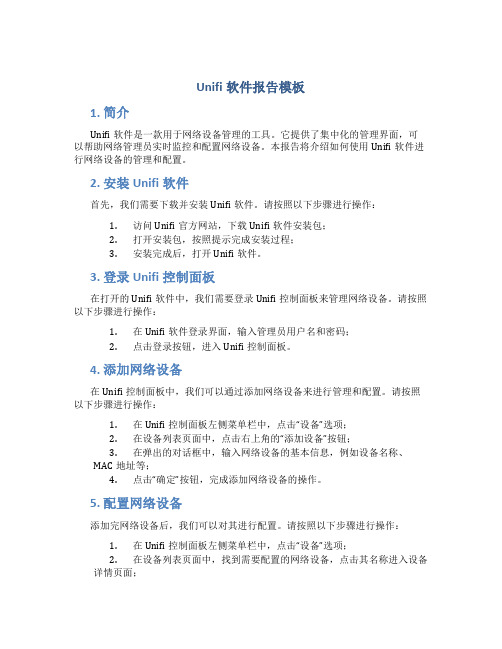
Unifi软件报告模板1. 简介Unifi软件是一款用于网络设备管理的工具。
它提供了集中化的管理界面,可以帮助网络管理员实时监控和配置网络设备。
本报告将介绍如何使用Unifi软件进行网络设备的管理和配置。
2. 安装Unifi软件首先,我们需要下载并安装Unifi软件。
请按照以下步骤进行操作:1.访问Unifi官方网站,下载Unifi软件安装包;2.打开安装包,按照提示完成安装过程;3.安装完成后,打开Unifi软件。
3. 登录Unifi控制面板在打开的Unifi软件中,我们需要登录Unifi控制面板来管理网络设备。
请按照以下步骤进行操作:1.在Unifi软件登录界面,输入管理员用户名和密码;2.点击登录按钮,进入Unifi控制面板。
4. 添加网络设备在Unifi控制面板中,我们可以通过添加网络设备来进行管理和配置。
请按照以下步骤进行操作:1.在Unifi控制面板左侧菜单栏中,点击“设备”选项;2.在设备列表页面中,点击右上角的“添加设备”按钮;3.在弹出的对话框中,输入网络设备的基本信息,例如设备名称、MAC地址等;4.点击“确定”按钮,完成添加网络设备的操作。
5. 配置网络设备添加完网络设备后,我们可以对其进行配置。
请按照以下步骤进行操作:1.在Unifi控制面板左侧菜单栏中,点击“设备”选项;2.在设备列表页面中,找到需要配置的网络设备,点击其名称进入设备详情页面;3.在设备详情页面中,可以进行各种配置操作,例如调整无线信号强度、设置访客网络等;4.完成配置后,点击页面底部的“应用更改”按钮,保存配置并应用到网络设备上。
6. 监控网络设备Unifi软件还提供了实时监控网络设备的功能。
请按照以下步骤进行操作:1.在Unifi控制面板左侧菜单栏中,点击“设备”选项;2.在设备列表页面中,可以查看各个网络设备的状态、连接数、速度等信息;3.点击具体设备名称,可以进一步查看该设备的详细信息和统计数据;4.根据需要,可以通过Unifi软件对网络设备进行重启、断开连接等操作。
Ubiquiti Networks
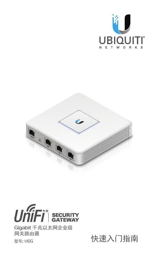
快速入门指南Gigabit 千兆以太网企业级网关路由器型号: USG简介感谢您购买 Ubiquiti Networks® UniFi®安全网关,它是UniFi 企业级系统的组成部分。
UniFi企业级系统包含UniFi控制器软件,可使您用Web浏览器管理网络。
UniFi控制器软件和用户指南可在/unifi下载本快速入门指南包括保修条款,适用于UniFi安全网关(型号:USG)。
物品清单(12V,1A)螺丝(M2.9x20, 数量2个)螺旋形地锚(M2.9, 数量2个)快速入门指南使用条款:所有以太网线必须使用CAT5(或以上)线缆。
客户有责任遵守所在地国家/地区的相关法规和室内布线要求。
UniFiLANUniFi安全网关WANInternet网络图示例所有UniFi设备都支持非现场管理控制器。
有关设置详情,请参见我们网站上的用户指南:/ unifiLEDs状态电源速度/链接/活动UniFi安全网关,或使用随附的UniFi安全网关固UniFi安全网关周围应留出墙壁安装将UniFi安全网关安装到墙壁上,需要一个电钻、一个6mm钻头和一把十字螺丝刀。
1. 使用6mm钻头钻出两个相距90mm的孔。
将螺丝固定锚插入每个孔。
90 mm2. 使用十字螺丝刀将螺丝安装到各个固定锚。
在螺丝头和墙壁之间留出大约3mm空间。
*640-00120-01*640-00120-01连接电源1. 将电源适配器连接到电源端口。
2. 将电源线连接到电源适配器。
将电源线的另一端连接到接地电源。
WAN上的以太网电缆连接到WAN端2. 将网络交换机上的以太网电缆连接到LAN端口。
注:LAN端口默认设置为DHCP服务器。
2. 将显示UniFi安装向导。
选择您喜欢的语言和国家/地区。
单击NEXT(下一步)。
4. 创建SSID和安全密钥。
单击NEXT(下一步)。
如果您的网络上没有任何UniFi AP,请单击跳过。
6. 查看UniFi控制器设置。
Unified Brands 产品说明书.pdf_1720086257.0799437

This manual provides information for:OPERATOR MANUAL IMPORTANT INFORMATION, KEEP FOR OPERATORPART NUMBER 162954 REV A (08/13)THIS MANUAL MUST BE RETAINED FOR FUTURE REFERENCE.READ, UNDERSTAND AND FOLLOW THE INSTRUCTIONS ANDWARNINGS CONTAINED IN THIS MANUAL.FOR YOUR SAFETY Do not store or use gasoline or other flammable vapors and liquids in the vicinity of this or any other appliance.NOTIFY CARRIER OF DAMAGE AT ONCEIt is the responsibility of the consignee to inspect the container upon receiptof same and to determine the possibility of any damage, including concealeddamage. Unified Brands suggests that if you are suspicious of damage tomake a notation on the delivery receipt. It will be the responsibility of the con-signee to file a claim with the carrier. We recommend that you do so at once.Manufacture Service/Questions 888-994-7636.Information contained in this document is known to be current and accurate at the time of printing/creation. Unified Brands recommends referencing our product line websites,, for the most updated product information and specifications.MODEL ST-6EGROEN STEAMERWARNING: THE UNIT MUST BE INSTALLED BY PERSONNEL QUALIFIED TO WORK WITH ELECTRICITY AND PLUMBING. IMPROPER INSTALLATION CAN CAUSE INJURY TO PERSONNEL AND/OR DAMAGE TOTHE EQUIPMENT. THE UNIT MUST BE INSTALLED IN ACCORDANCE WITH APPLICABLE CODES.CAUTION: SHIPPING STRAPS ARE UNDER TENSION AND CAN SNAP BACK WHEN CUT.CAUTION: DO NOT INSTALL THE UNIT IN ANY WAY WHICH WILL BLOCK THE REAR VENTS, OR WITHIN 2 INCHES OF A HEAT SOURCE SUCH AS A BRAISING PAN, DEEP FRYER, CHAR BROILER OR KETTLE.CAUTION: LEVEL THE UNIT FRONT TO BACK, AND PITCH IT SLIGHTL Y TO THE FRONT, TO AVOIDDRAINAGE PROBLEMS.WARNING: FOLLOW THE WIRING DIAGRAM EXACTL Y WHEN CONNECTING A UNIT TO AVOIDDAMAGE OR INJURY. WIRING DIAGRAM IS LOCATED ON THE INSIDE OF THE RIGHT PANEL.CAUTION: DO NOT USE PLASTIC PIPE. DRAIN MUST BE RATED FOR BOILING WATER.WARNING: DO NOT CONNECT THE DRAIN DIRECTL Y TO A BUILDING DRAIN.WARNING: BLOCKING THE DRAIN IS HAZARDOUS.IMPORTANT: IMPROPER DRAIN CONNECTION WILL VOID WARRANTY.WARNING: WHEN YOU OPEN THE DOOR, STAY AWAY FROM STEAM COMING OUT OF THE UNIT.STEAM CAN CAUSE BURNS.WARNING: BEFORE CLEANING THE OUTSIDE OF THE STEAMER, DISCONNECT THE ELECTRIC POWER SUPPL Y.KEEP WATER AND CLEANING SOLUTIONS OUT OF CONTROLS AND ELECTRICAL COMPONENTS.NEVER HOSE OR STEAM CLEAN ANY PART OF THE UNIT.WARNING: ALLOW COOKING CHAMBER TO COOL COMPLETEL Y BEFORE CLEANING.WARNING: USE MILD CLEANING AGENTS ONL Y. CAREFULL Y READ THE WARNINGS AND FOLLOW THE DIRECTIONS ON THE LABEL OF EACH CLEANING AGENT. USE SAFETY GLASSESAND RUBBER GLOVES AS RECOMMENDED BY CLEANING AGENT MANUFACTURER.WARNING: DO NOT PUT HANDS OR TOOLS INTO THE COOKING CHAMBER UNTIL THE FAN HASSTOPPED TURNING.WARNING: DO NOT OPERATE THE UNIT UNLESS THE REMOVABLE RIGHT SIDE PANEL HAS BEEN RETURNED TO ITS PROPER LOCATION.NOTICE: DO NOT USE A CLEANING AGENT THAT CONTAINS ANY SULFURIC ACID, OR ANYCHLORIDE, INCLUDING HYDROCHLORIC ACID. IF THE CHLORIDE CONTENT OF ANYPRODUCT IS UNCLEAR, CONSUL T THE MANUFACTURER. DO NOT USE A CLEANING ORDELIMING AGENT THAT CONTAINS MORE THAN 30% PHOSPHORIC ACID.NOTICE: DO NOT USE ANY DEGREASER THAT CONTAINS POTASSIUM HYDROXIDE OR SODIUM HYDROXIDE OR THAT IS ALKALINE.WARNING: USE OF ANY REPLACEMENT PARTS OTHER THAN THOSE SUPPLIED BY UNIFIED BRANDS OR THEIR AUTHORIZED DISTRIBUTOR VOIDS ALL WARRANTIES AND CAN RESUL T IN BODIL Y INJURY TOTHE OPERATOR AND DAMAGE THE EQUIPMENT. SERVICE BY OTHER THAN FACTORY-AUTHORIZEDPERSONNEL WILL VOID ALL WARRANTIES.WARNING: HIGH VOL TAGE EXISTS INSIDE CONTROL COMPARTMENTS. DISCONNECT FROM BRANCH CIRCUIT BEFORE SERVICING. FAILURE TO DO SO CAN RESUL T IN INJURY OR DEATH.2 OM-ST-6EImportant Operator Warnings ........................................................page 2 References..................................................................................... page 3 Equipment Description.................................................................. page 4 Inspection and Unpacking ............................................................ page 4 Installation .................................................................................. page 5-6 Initial Start-Up............................................................................... page 7 Operation ...................................................................................... page 8 Cleaning................................................................................... page 9-10 Maintenance................................................................................. page 11 Troubleshooting............................................................................ page 12 Wiring Diagram ........................................................................... page 19 Service Log ................................................................................... page 20 UNDERWRITERS LABORATORIES, INC.333 Pfingsten RoadNorthbrook, Illinois 60062NFPA/70The National Electrical CodeNATIONAL SANITATION FOUNDATION789 N. Dixboro Rd.Ann Arbor, Michigan 48113-0140NATIONAL FIRE PROTECTION ASSOCIATION60 Batterymarch ParkQuincy, Massachusetts 02269INTERTEK (ETL)1950 Evergreen Blvd, Suite 100Duluth, GA 30096OM-ST-6E 34 OM-ST-6EYour ST-6E steamer is designed to give years of service. It has a stainless steel cavity (cooking chamber) which is served by an electric-heated atmospheric steam generating reservoir.Each cavity holds up to six steam table pans (12” x 20” x 2-1/2” deep) as shown below.A stainless steel case encloses the cavity, the steam generating reservoir and the control compartment that houses electrical components. Operating controls are on the front panel.The drain system on all models includes a spray condenser, which cools drain water.Inspection & UnpackingYour steamer is delivered completely assembled strapped to a skid. On receipt, inspect carefully for exterior damage.Carefully cut the straps. Be careful to avoid personal injury or equipment damage.Write down the model number, serial number and installation date. Keep this information for reference. Space for these entries is provided at the top of the Service Log in the back of this manual.When starting installation, check packing materials to make sure loose parts such as the condensate drip tray are not discarded with this material.CAUTIONSHIPPING STRAPS ARE UNDER TENSIONAND CAN SNAP BACK WHEN CUT.OM-ST-6E 51. Minimum Clearances: The steamer requires the following minimum clear-ances to any surface, combustible or non-combustible. Right Side 2 inches Left Side 2 inches Rear 6 inches Steam Free Zone: The steamer can be damaged by steam from external sources. Do not install the steamer over a steam venting drain. Ensure that steam is not present in an area bounded by the footprint of the steamer and a circle 18 inches in radius about the right rear corner of the steamer (see Figure A at left). 2. Electrical Supply Connections (current and power demands for each unit are as shown below) A. Panel Removal - Right Side Open the wiring and control panel by removing screws from the right side panel. Remove and set aside. B. Supply Voltage The unit must be operated at the rated name plate voltage. The name plate can be found on the rear of the unit. C. Phase Selection Refer to steamer wiring diagram and element wiring on pages 20 and 21 for wiring information. D. Terminal Block The terminal block for incoming power is located at the back of the control compartment. The ground terminal is located in the wiring compartment near the terminal block. E. Supply Wire The equipment grounding wire must comply with the National Electrical Code (NEC) requirements. The wiring diagram on the inside of the unit’s right side cover gives directions for proper connection of the terminal block. The wire must be used or the unit will not meet Underwriters Laboratories and NEC requirements. The electric hole is sized for a one-inch conduit fitting.F. Branch Circuit Protection Each steamer, including individual units of stacked models, should have its own branch circuit protection and ground wire. FIGURE ACAUTIONWARNING, .6 OM-ST-6E 3. Water Connection(s) Install a check valve to prevent back flow in the incoming cold water line, as required by local plumbing codes. Water pressure in the line should be between 30 and 60 PSI. If pressure is above 60 PSI, a pressure regulator will be needed. These pressures must provide the 1.5 gallons per minute required for proper steamer function. A 3/4 inch female NH connector (garden hose type) is used to attach the water supply to the inlet valve. Minimum inside diameter of the water feed line is 1/2 inch. Use a washer in the hose connection. Do not allow the connection to leak, no matter how slowly. Do not over-tighten hose connections. This equipment is to be installed to comply with the basic plumbing code of the Building Officials and Code Administrators International, Inc. (BOCA) and the Food Service Sanitation Manual of the Food and Drug Administration (FDA). 4. Drain Connection Level the steamer front to back, and pitch it slightly to the front (maximum 1/4 inch) by adjusting the optional legs or the bullet feet on the optional stand. There must be a free air gap between the end of the hose and the building drain. The free air gap should be as close as possible to the unit drain. There must also be no other elbows or other restrictions between the unit drain and the free air gap. Install the drain line with a constant downward pitch (see Figure B at left). IMPORTANT: Do not allow water traps in the line. A trap can cause pres-sure build-up in the cavity, which may cause the door gasket to leak. For proper drain line connection, the drain line must have a constant downward pitch of at least 1/4” per foot. Observe local code regarding air gap spacing and drain connections.5. Counter-Mounted Units This section is applicable when the steamer will be mounted to a counter. All four edges of the bottom of the steamer must be sealed with RTV to the counter if the 4 inch legs are not used. Counter must be made of a noncombustible material such as metal or tile.FIGURE BAfter the steamer has been installed, test it to ensure that the unit is operating correctly.1. Remove all literature and packing materials from the interior and exterior of theunit.2. Make sure the water supply line is open and the drain valve handle is in theclosed position.3. Turn on electrical service to the unit. The steamer will not operate withoutelectrical power. Do not attempt to operate the unit during a power failure.NOTE: The door MUST be closed for the elements to operate.4. To turn unit on, toggle the rocker switch to the ON position.5. Toggle the mode selector switch to full steam mode (top position).6. When the steam generating reservoir has filled with water, the heaters willbegin heating. Within 20 minutes the remote Timer should indicate that thesteamer is ready.7. To shut down the unit, toggle the ON/OFF switch to the OFF position. Wait 30minutes and rotate the drain valve to open position to drain the water reservoir.8. If the steamer operates as described, the unit is functioning correctly and readyfor use.OM-ST-6E 78 OM-ST-6E A. Controls Operator controls are on the front right of the unit. The Control Panel has the following: 1. The ON/OFF power switch starts the steamer, filling it with water and is ready for use. It also shuts it OFF.B. Operating Procedure 1. Press the ON/OFF switch located on the control panel. The steam generating reservoir will fill. In approximately 15-20 minutes the remote Timer will indicate that the steamer is ready. 2. Load food into pans in uniform layers. Pans should be filled to about the same levels and should be even on top. 3. Open the door and slide the pans onto the supports. If you will only be steaming one pan, put it in the middle position. 4. Close the door. Press the desired product button on the remote Timer. The Timer will beep when the time has elapsed and the product is done. 5. Open the door. Remove the pans from the steamer, using hot pads or oven mitts to protect your hands from the hot pans. 6. To shut down the unit, press the ON/OFF rocker switch to OFF. NOTE: The steamer was designed to drain only when the manual drain is opened.WARNINGWHEN YOU OPEN THE DOOR, STAY AWAYFROM STEAM COMING OUT OF THE UNIT. STEAM CAN CAUSE BURNS.ro trial versionOM-ST-6E 9To keep your steamer in proper working condition, use the following procedure to clean the unit. This regular cleaning will reduce the effort required to clean the steam generator and cavity. A. Suggested Supplies 1. Mild detergent 2. Stainless steel exterior cleaner Spray DeGreaser (Part Number 156704) 3. Cloth or sponge 4. Brush with soft bristles 5. Spray bottle 6. Measuring cup 7. Nylon pad 8. Towels 9. Plastic disposable gloves 10. Funnel B. Procedure 1. Exterior Cleaning a. Prepare a warm solution of the mild detergent as instructed by the supplier. Wet a cloth with this solution and wring it out. Use the moist cloth to clean the outside of the unit. Do not allow freely running liquid to touch the controls, the control panel, any electrical part, or any louver on the rear panels. b. To remove material which may be stuck to the unit, use a fiber brush or a plastic or rubber scraper with a detergent solution. c. Stainless steel surfaces may be polished with a recognized stainless steel cleaner. 2. Interior Cleaning Daily cleaning must be done in order to enhance the performance and prolong the life of your steamer.IMPORTANTDO NOT USE ANY METAL MATERIAL (SUCH AS METAL SPONGES) OR METAL IMPLEMENTS (SUCH AS A SPOON, SCRAPER OR WIRE BRUSH) THAT MIGHT SCRATCH ANY STAINLESS STEEL SURFACE. SCRATCHES MAKE THE SURFACE HARD TO CLEAN AND PROVIDE PLACES FOR BACTERIA TO GROW. DO NOT USE STEEL WOOL, WHICH MAY LEAVE PARTICLES EMBEDDED IN THE SURFACE, WHICH COULD EVENTUALLY CAUSE CORROSION AND PITTING.10 OM-ST-6E CLEANING STEPS: STEP 1 - Press OFF switch to turn steamer OFF and open steamer door. STEP 2 - CAUTION: allow the steamer to cool completely before cleaning. STEP 3 - Remove left pan rack by lifting rack up and pulling away from cavity wall. STEP 4 - Remove rack assembly by lifting rack up and pulling away from cavity wall. STEP 5 - Clean pan racks to remove food soils. These may be cleaned in a dishwasher. STEP 6 - Use a mild detergent to wipe down the entire steamer cavity to remove food and scale particles. Carefully clean float probes if food residue or loose scale is present. A thin layer of tightly bound scale is normal and will not affect steamer performance. If scale is excessive, then refer to deliming instructions below. STEP 7 - Remove drain strainer and clean thoroughly to remove any build-up of debris. STEP 8 - Replace pan racks. Steamer is now cleaned and ready to use. DELIMING INSTRUCTIONS: • When using Groen Water Treatment System use vinegar as a deliming agent. • Groen approved delimer may be used to remove excessive scale build-up. STEP 1 - After following all cleaning steps 1 through 7 listed above, turn steamer on and allow water to enter steamer cavity. STEP 2 - Pour 1 cup of vinegar or delimer into steamer cavity and shut door. STEP 3 - Set steamer timer to 30 minutes and allow steam cleaning to occur. STEP 4 - After 30 minutes cleaning cycle is complete, turn steamer OFF and allow to cool completely. STEP 5 - Open steamer door and wipe down the entire steamer cavity to remove loosened scale particles. Carefully clean float probes if loose scale is present. STEP 6 - Replace pan racks. Steamer is now cleaned and ready to use. FLOAT PROBE ORIENTATION NOTE: Inside view of steamer cavity with no water present. High level float probe swings up.HIGHFLOATThe steamer is designed for minimum maintenance and no user adjustments should be necessary. Certain parts may need replacement after prolonged use. If there is a need for service, only Authorized Service Agents should perform the work.If steam or condensate is seen leaking from around the door, take the following steps:1. Check the door gasket. Replace it if it is cracked or split.2. Inspect the cooking chamber drain to be sure it is not blocked.3. Adjust the door latch pin to allow for changes that might occur as thegasket ages.a. Loosen the lock nut at the base of the latch pin, then turn the latchpin 1/4 turn clockwise, and tighten the lock nut.b. After adjustment, run the unit to test for further steam leakage.c. If there is still leakage, repeat the adjustmentd. Continue adjusting the pin clockwise until the door fits tightlyenough to prevent leakage. The hinge may also be adjusted.Your steamer is designed to operate smoothly and efficiently if properly maintained. However, the following is a list of checks to make in the event of a problem. Wiring diagrams are furnished inside the service panel. If an item on the check list is marked with (*), it means that the work should be done by a Authorized Service Agent.ITEM NO.PART NUMBER DESCRIPTIONDefault/QTY.1156151PANEL SIDE RIGHT 6-PAN ASSY 12156152PANEL SIDE LEFT 6-PAN ASSY13094151TRAY DRIP 14156396WELDMENT,TOP COVER,4-PAN 15145297WELDMENT,CAVITY VENT NOVACUUM16070467SHOULDER SCREW -DRIP TRAY 27004173SCREW,TRS HEAD 10-32X 3/8178073242LOCTITE #2420.1OZ 9156507PANEL ACCESS1SECTION B-BITEM NO.PART NUMBER DESCRIPTION QTY.1156483WELDMENT,DRAIN MANIFOLD ASSY,4-PAN ELECTRIC1 2147566HOSE,SHORT VENT1 3127525CLAMP,HOSE,CONSTANT TENSION,2 4140164HOSE,SHORT STEAM INLET1 5138457CLAMP,CONSTANT TENSION CTB-274 6071235VALVE-WATER FEED3/4 R17071256NUT HEXHEAD KEPS10-3218093482CLAMP HOSE LOW PRESSURE6 9505090HOSE BLACK RUBBER3/8"ID X10"LG1 10013650TEE,1/2"NPT-BRASS1 11139126ELBOW,90DEG1/2MPT X3/8112142548ELBOW1/2"NPT TO3/4HOSE BARB90DEG.113156478MPT TO FPT BRASS BALL VALVE1/2NPT1 14012809NUT,HEXAGON3/8-241 15141668HANDLE,SHAFT1 16156479SHAFT,DRAIN ACTUATOR117GVR-0002BRACKET,DRAIN VALVECONNECTION1 18125954HOSE,STEAM UNIT18"LONG1 19092124CLEAR3/8HOSE1 20144481REDUCER,WATER FLOW, .110ID1 21147371REDUCER,FLOW1 22156487DRAIN THERMOSTAT123071297NUT HEXAGON KEPS4-402ITEM NO.PART NUMBER DESCRIPTIONQTY.1156401CONTROL PANEL ASSEMBLYELECTRIC12069789SCREW HEX SLOTTED HD W/WASHER#8-32X 3/8"24155548POWER SWITCH,WITH GREENINDICATOR LIGHT 15096857SWITCH,DOOR18096841SCREW #4-40X 1/4"HEX MS 29153505FAN,24VDC MUFFIN 80MM 110143664GUARD,80MM FAN,PLASTIC 111140182SCREW,6-32X 2LG HEX HD SLOT412119855NUT,6-32LOCK INSERT 413149880PROBE,FLOAT BLACK214144484THERMOSTAT115156400PLATE,READY SENSOR116156491THERMOSTAT,CLOSE 180DEG F117162189REPEAT CYCLE TIMER1 1626057-2TEMP CONTROLLER1 15071487RECTIFIER, BRIDGE-COMBO1 14071485SCREW HEX SLOTTED1 13156486BEEPER1 12116100SCREW, #10-32 X .752 11069789SCREW HEX SLOTTED HD W/WASHER #8-32 X 3/8"12 10005056SCREW ROUND HEAD 8-32 1 1/4"2 9121733.A RELAY, 24 VAC DPDT1 8119814RELAY, 24 VAC DPST1 7070185TERMINAL BLOCK1 6106412MECHANICAL LUG,GROUND, #2 - #81 5160919FUSE BLOCK ASSY1 4137441TRANSFORMER, 40VA, 208-240/60/31 3119811CONTACTOR, 4 POLE 40FLA 2 2003888TERMINAL BLOCK 3-POLE1 1156402PANEL, HIGH VOLTAGE ASSEMBLY1 ITEM NO.PART NUMBER DESCRIPTION QTY.ITEM NO.PART NUMBER DESCRIPTION QTY.1156320INSULATION32156318BRACKET, ELEMENT HOLD-DOWN,LEFT & RIGHT SIDE 23156319BRACKET, ELEMENT HOLD-DOWN,MIDDLE14156322PANEL,INSULATION HOLD-DOWN15154644ELEMENT, 208V 750W VRC126012940NUT,HEXKEPS 1/4"-2012INSULATION HOLD DOWN PANELUP-SIDE DOWN WITHUP-SIDE DOWN WITHOUTINSULATION HOLD DOWN PANELModel No:Purchased From: Serial No:Location:Date Purchased:Date Installed: Purchase Order No:For Service Call:OM-ST-6E 211055 Mendell Davis Drive • Jackson MS 39272888-994-7636 • 601-372-3903 • Fax 888-864-7636PART NUMBER 162954 REV A (08/13)© 2013 Unified Brands. All Rights Reserved. Unified Brands is a wholly-owned subsidiary of Dover Corporation.。
tp-link无线ap使用说明书
目录第1章产品概述 (1)1.1.产品简介 (1)1.2.特性和规格说明 (1)1.2.1.主要特性 (1)1.2.2.规格 (1)第2章硬件描述 (2)2.1.面板布置 (2)2.1.1.前面板 (2)2.1.2.后面板 (3)2.2.复位 (3)2.3.系统需求 (3)2.4.安装环境 (3)第3章TCP/IP配置 (5)第4章配置指南 (6)4.1.启动和登录 (6)4.2.运行状态 (7)4.3.QSS安全设置 (7)4.4.网络参数 (19)4.5.无线设置 (19)4.5.1.基本设置 (20)4.5.1.1.Access Point (20)4.5.1.2.Multi-SSID (21)4.5.1.3.Client (21)4.5.1.4.Repeater (22)4.5.1.5.Universal Repeater (23)4.5.1.6.Bridge with AP (23)4.5.1.7.AP扫描 (24)4.5.2.无线安全设置 (25)4.5.2.1.WEP (26)4.5.2.2.WPA/WPA2 (26)4.5.2.3.WPA-PSK/WPA2-PSK (27)4.5.3.无线MAC地址过滤 (27)4.5.4.无线高级设置 (29)4.5.5.无线流量检测 (30)4.5.6.主机状态 (31)4.6.DHCP服务器 (31)4.6.1.DHCP服务 (32)4.6.2.客户端列表 (32)4.6.3.静态地址分配 (33)4.7.系统工具 (33)4.7.1.SNMP (34)4.7.2.诊断工具 (35)4.7.3.看门狗 (35)4.7.4.软件升级 (36)4.7.5.恢复出厂设置 (37)4.7.6.备份和载入配置 (37)4.7.7.重启系统 (38)4.7.8.修改登录口令 (39)4.7.9.系统日志 (39)附录A FAQ (40)附录B POE的使用 (41)第1章 产品概述1.1. 产品简介TL-WA801N无线接入器使移动用户或难以实施布线工程的用户能够轻松的访问网络,将有线以太网扩展到整幢大楼或整个园区。
- 1、下载文档前请自行甄别文档内容的完整性,平台不提供额外的编辑、内容补充、找答案等附加服务。
- 2、"仅部分预览"的文档,不可在线预览部分如存在完整性等问题,可反馈申请退款(可完整预览的文档不适用该条件!)。
- 3、如文档侵犯您的权益,请联系客服反馈,我们会尽快为您处理(人工客服工作时间:9:00-18:30)。
包装清单
UniFi企业无线节点挂墙托架天花板固定板控制CD及使用手册
电源线M3X30平头螺丝24V以太网供电适配器带齿状垫片的M3螺母
M2 9x20自攻钉M3x20 螺旋型地锚
系统需求
·Windows XP,Vista,Win 7 ,Mac OS X
·JAVA运行环境1.6版本或其以上版本平台
·浏览器:火狐浏览器,谷歌浏览器或微软IE8及其以上版本
网络技术需求
·可运行DHCP的网络(使AP和调试后的无线客户端获得一个IP)
·接入点和管理站计算机连接在同一个2层交换机
网络实例图解
硬件安装
UniFi网络AP由以太网供电适配器供电驱动,安装AP执行下类步骤:
1. 连接一根网线到AP网口上
2. 连接电源线到以太网配置器的电源接口,连接另一端到电
源输出插座.
3. 把连接AP的网线连接到以太网供电适配器
小贴士:如果你准备把AP安装在天花板上,先把AP固定在天花板上,然后在把连接AP的网线连接到以太网供电适配器。
下面就是以太网供电连接的全貌图
安装AP
UniFi企业版AP可以装在墙或天花板上。
请按照下了步骤安装:
挂墙
1. 把挂墙托架对齐,Wall Mount字样朝上。
在托架上有水平
线和垂直线,以便校对定位
2. 用铅笔来标注墙上的洞
3. 用6毫米钻头在墙上打孔
4. 在墙中插入3根地锚
5. 把自攻钉穿过托架拧如地锚中,固定牢靠
6. 对其AP与支架上的槽口
7. 顺时针转动AP到底,使二者相扣在一起
挂在天花板上
1. 除去天花板瓷砖
2. 把安装在天花板上的固定盘对准瓷砖正面的中心
3. 在天花板瓷砖上用3.5毫米钻头电钻为3个平头螺丝打三
个孔
4. 切或钻一个大约25毫米的圆孔,大小与天花板固定盘上
的圆孔相当。
这个孔用来过网线。
5. 用3个平头螺丝和3个带齿状垫片的螺母来固定挂墙托架
和天花板固定板
6.把网线通过圆孔穿入并且把AP和挂墙托架的槽口对齐
小贴士:UniFi企业版AP支持由以太网供电适配器提供的被动网络供电。
如果你想要用一个符合802.3af标准的交换机来对AP进行供电,Ubiquiti Networks公司提供了可供选择的802.3af适配器以便即时的把任何以太网供电装置改变为一个符合802.3af标准的满伏48V的产品。
产品细节可以在我们的网站上/8023af获取。
7. 顺时针转动AP到底,使二者相扣在一起
软件安装
把UniFi控制器光盘插入光驱然后依照你的电脑类型的说明进行操作
苹果电脑
1. 点击Install键
2. 点击Continue然后根据屏幕上的说明来安装软件
3. 进入Go>Applications路径,双击UniFi键
在后面会介绍到配置UniFi控制软件
电脑用户
1. 运行UniFi-installer.exe
2. 点击Install
3. 如果你的电脑没有安装JAVA 1.6版或其以上版本,你将
被提示安装。
点击Install继续
4. 点击Next
5. 选择安装选项后确定开始UniFi控制器,点击Finish
小贴士:UniFi控制软件也可以从Start>All Programs 中安装
配置UniFi控制软件
1. UniFi控制软件将要启动,当选项变成有效的,点击
Launch a Browser to Manage Wireless Network
2.选择你的语言和国家,点击Next 2. 选择你想要配置的设备,点击Next
3. UniFi 安装向导为你的设备创造一个安全的一次无线网,
进行下面的步骤:
a.在Secure SSID区域输入无线网的名称(SSID)b.输入一个密码用于网络
c.如果你想要允许游客访问,选择Enable Guest Access并且在Guest SSID中输入客户名称d.点击Next
5.输入用于访问管理界面的用户名密码,在Confirm中重复密码,点击Next
6.检查你的设置。
点击Back来做出修改或点击Finish来保存设置。
一旦完成你将通过浏览器重新导入到管理界面
恭喜你,你的无线网络现在已经被配置完成了。
UniFi控制器管理界面的登陆界面将会出现。
输入用户名和密码然后点击Login。
通过控制器管理界面,你可以管理你的无线网络,查看网络统计。
想要了解更多的AP配置和使用,请查阅光盘中的用户指南。
