ZH-502说明书
ZH-S 用户手册说明书
AC66781 重要事项安全使用本产品之前,请仔细阅读本用户手册,并妥善保管以备日后参考。
危险• 切勿让水或任何其它液体或易燃性清洁剂进入产品,以免发生触电和/或火灾。
• 切勿用水或任何其它液体或(易燃性)清洁剂来清洁产品,以免发生触电和/或火灾。
• 切勿在产品周围喷洒杀虫剂或香水等任何可燃材料。
警告• 在将产品连接电源之前,请先检查产品所标电压与当地的供电电压是否相符。
• 如果电源软线损坏,为避免危险,必须由制造厂或其维修部或类似的专职人员来更换。
• 如果插头、电源线或产品本身受损,请勿再使用本产品。
• 本产品适合由 8 岁或以上年龄的儿童以及肢体不健全、感觉或精神上有障碍或缺乏相关经验和知识的人士使用,但前提是有人对他们使用本产品进行监督或指导,以确保他们安全使用,并且让他们明白相关的危害。
不得让儿童玩耍本产品。
请勿让儿童在无人监督的情况下清洁和保养产品。
• 请勿堵塞进风和出风口,例如不要将物体放置在出风口上或进风口前方。
• 确保异物未通过出风口进入产品内部。
小心• 本产品不能替代正常通风、日常吸尘或者在烹饪时使用的抽油烟机。
• 如果连接产品的电源插座接触不良,则产品的插头可能会变得很热。
确保所连接的电源插座接触良好。
• 一定要在干燥、稳固、平整且水平的表面上放置和使用本产品。
• 产品的后侧及两侧均要留出至少 20 厘米的空间,产品上方至少要留出 30 厘米的空间。
• 切勿在本产品上放置任何物品。
• 请勿坐在或站在产品上面。
坐在或站在产品上面可能导致潜在的人身伤害。
• 切勿将产品直接放在空调下方,以防冷凝水滴到产品中。
2ZH-S简体中文3ZH-S • 打开产品电源之前,务必确保已经正确安装所有过滤网。
• 只能使用飞利浦专门为本产品设计的原装过滤网。
切勿使用任何其它过滤网。
• 燃烧滤网可能会造成不可逆转的人体危害和/或危及其他生命。
请勿将滤网用作燃料或类似用途。
•请勿用硬物敲击本产品(尤其是进风口和出风口)。
裕华YHIP502(Ex)防爆号筒式扬声器使用说明书

常州裕华常州裕华电子设备制造有限公司XK06-123-00251生产许可证编号:安装、使用前请仔细阅读使用说明书。
1. 安装1、安装、使用前请仔细阅读使用说明书,遵守警告事项。
2、在对设备进行维护和检修之前,请务必切断电源。
3、避免在有油烟、灰尘严重、高温、结露的场所打开设备。
4、请按本说明书要求正确安装电缆,否则有可能产生故障。
5、在对设备进行维护时,一定要注意对隔爆面的保护;避免金属碎屑或其它物质进入设备内部。
6、请勿对设备进行分解或改造。
2. 环保本公司所生产的各类产品,其中有可能包含对环境造成污染的零部件,如电路板、电子元器件、塑料制品、润滑油脂等,当设备维护或报废时,请注意对这些污染源进行收集、控制,不要随意丢弃,应当移交给相关环保部门进行处理,以免对环境造成不良影响。
2目录1. 概述: (4)2. 技术指标 (4)2.1型号组成 (4)2.2认证 (4)2.3电气指标 (4)2.4机械指标 (5)2.5环境条件 (5)2.6产品尺寸 (5)2.7安装尺寸 (6)3. 安装 (6)3.1电缆的处理 (6)4. 防爆结构说明 (7)5. 设备安装注意事项 (8)6. 运输、贮存 (8)7. 安装件及附件 (8)8. 质量保证 (8)9. 公司声明 (9)341. 概述:YHIP502(Ex )防爆号筒式扬声器可与各种功放设备配套使用,作扩音呼叫或报警用。
YHIP502(Ex )防爆号筒式扬声器是严格按GB3836.1-2000《爆炸性气体环境用电气设备第1部分通用要求》和GB3836.2-2000《爆炸性气体环境用防爆电气设备第2部分:隔爆型d 》等标准设计制造的,隔爆腔外壳采用全不锈钢结构,防护等级IP54级。
YHIP502(Ex )防爆号筒式扬声器是与YHIP700系列数字型防爆工业话站配套使用的通讯系统中的扩音单元,应用于大型厂矿企业。
可用于有爆炸性危险环境的场所,如石油、化工、仓储、港口、矿山等行业。
ZH-WI-QM-28 502胶水安全技术说明书(MSDS)资料

立即用水清洗,至少15分钟以上。洗完后,立即请医生诊治;就医;
吸入:
如果吸入蒸气后有不适感,要立即转移至空气新鲜的场所,迅速请医生诊治
食入:
用水清洗口腔。大量饮水在胃内稀释并吐出,之后立即请医生处治。
第五部分:消防措施
危险特性:
可燃,在火焰中释放出刺激性或有毒烟雾
有害燃烧产物:
一氧化碳、二氧化碳、氧化氮
第七部分:操作处置与储存
操作注意事项:
操作时保持现场通风。远离火源,戴护目镜避免皮肤接触与误食。
储存注意事项:
储存于阴凉、干燥、通风、避光处。保持容器密封,防止产品受潮。不可与醇、有机胺存放在一起,以免聚合变质。
第八部分:接触控制/个体防护
职业接触限值:
无资料
中国MAC(mg/m3):
无资料
前苏联MAC(mg/m3):
第九部分:理化特性
主要成分:
α-氰基丙烯酸乙酯,阻聚剂、增稠剂、增强剂、加速剂
外观与性状:
无色透明液体,有刺激性气味;
pH:
5-6
熔点(℃):
无资料
沸点(℃):
54~56
相对密度(水=1):
1.026(25℃)
相对蒸气密度(空气=1):
无资料
饱和蒸气压(kPa):
无资料
燃烧热(kJ/mol):
无资料
中文名称2:
瞬间强力胶(a-氰基丙稀酸乙脂)
英文名称2:
Super Glue
第二部分:成分/组成信息
有害物成分
含量
CAS No.
刺激气味
/
/
第三部分:危险性概述
危险性类别:
无资料
侵入途径:
带座轴承参数
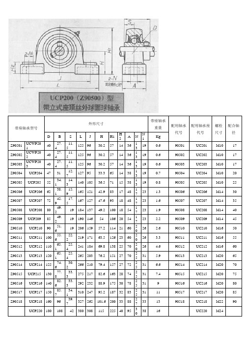
UCPH200型带高中心立式座顶丝外球面球轴承参数表UCPH200(ZH90500)型带高中心立式座顶丝外球面球轴承UCPA200型带窄立式座顶丝外球面球轴承参数表:PA200|(ZA!»5<»‘二丝夕阳三UCFU200带方形座顶丝外球面球轴承参数表UCF300带方形座顶丝外球面球轴承带方形座顶丝外球面球轴承|UCFLU200带菱形座顶丝外球面球轴承参数表U<FA200(LA9II5OO)型带可调菱形座顶丝外球面球轴承UCFA200型带可调菱形座顶丝外球面球轴承参数表UCFA200型带可调菱形座顶丝外球面球轴承参数表UCFA200(LA90500)型带可调菱形座顶丝外球面球轴承UCFC200带凸台圆形座顶丝外球面球轴承参数表UCK200带滑块座顶丝外球面球轴承参数表UCT214125 74.6 30.2 224 137 21 167 151 70 26 4641 32 70 7.3UC214T21470UCT215130 77.8 33.3 232 140 21 167 151 70 26 4841 32 70 7.7UC215T21575UCT216140 82.6 33.3 235 140 21 184 165 70 26 5141 32 70 8.4UC216T21680UCT217 150 85.7 34.1 260 162 29 198 173 73 30 5448 38 7311UC217T21785带座轴承型号外形尺寸带座轴承重量配用轴承代号 配用轴承座代号配合轴径D BS L L1 L 2 HH1 A A 1A2 NN 1 N2 Kg K90605 UCT30562 38 15 122 76 12 89 80 36 12 26 26 16 36 1.4 90605 UC305 K605 T305 25 K90606 UCT30672 43 17 137 85 14 100 90 41 16 28 28 18 41 1.8 90606 UC306 K606 T306 30 K90607 UCT30780 48 19 150 94 15 111 100 45 16 32 30 20 45 2.4 90607 UC307 K607 T307 35 K90608 UCT30890 52 19 162 100 17 124 112 50 18 34 32 22 503 90608 UC308 K608 T308 40 K90609 UCT309100 57 22 178 110 18 138 125 55 18 38 34 24 55 4 90609 UC309 K609 T309 45 K90610 UCT310110 61 22 191 117 20 151 140 61 20 40 37 27 61 5 90610 UC310 K610 T310 50 K90611 UCT311120 66 25 207 127 21 163 150 66 22 44 39 29 66 6.4 90611 UC311 K611 T311 55 K90612 UCT312130 71 26 220 135 23 178 160 71 22 46 41 31 71 7.6 90612 UC312 K612 T312 60 K90613 UCT313140 75 30 238 146 25 190 170 80 26 50 43 32 70 9.7 90613 UC313 K613 T313 65 K90614 UCT314150 78 33 252 155 25 202 180 90 26 52 46 36 85 11 90614 UC314 K614 T314 70 K90615 UCT315160 82 32 262 160 25 216 192 90 26 55 46 36 85 14 90615 UC315 K615 T315 75 K90616 UCT316170 86 34 282 174 28 230 204 102 30 60 53 42 98 16 90616 UC316 K616 T316 80 K90617 UCT317180 96 40 298 183 30 240 214 102 32 64 53 42 98 20 90617 UC317 K617 T317 85 K90618 UCT318190 96 40 312 192 30 255 228 110 32 66 57 46 106 22 90618 UC318 K618 T318 90 K90619 UCT319200 103 41 322 197 31 270 240 110 35 72 57 46 106 25 90619 UC319 K619 T319 95 K90620 UCT320215 108 42 345 210 32 290 260 120 35 75 59 48 115 32 90620 UC320 K620 T320 100 K90621 UCT321225 112 44 345 210 32 290 260 120 35 75 59 48 115 32 90621 UC321 K621 T321 105 K90622UCT322 240117 463852353832028513038 806552 1254090622UC322K622T322110型带滑块式座顶丝外球面球轴承IUCT300带滑块座顶丝外球面球轴承参数表--a«:-SUCC200带环形座顶丝外球面球轴承参数表卜UCC200(YWJ500)型带环形座顶丝外球面球轴承UCC300带环形座顶丝外球面球轴承参数表UCC300(Y90600)型带环形座顶丝外球面球轴承_。
binzel-abicor 型号 wh whpp zh 焊枪系统 使用说明书
T E C H N O L O G Y F O R T H E W E L D E R ´ S W O R L D . ZH使用说明WH / WHPPZH 焊枪系统WH / WHPPZH原厂操作手册中文翻译版© 厂家保留因印刷错误、不准确信息或产品改良而随时修订此操作手册的权利,恕不提前通知。
新版本操作手册也会涉及到此类更改。
在此操作手册中涉及的商标及注册商标归持有人/生产厂家所有。
如想获悉ABICOR BINZEL各国代理或合作伙伴的联系信息,请访问我们公司的主页1识别鉴定ZH-3 1.1标记ZH-3 2安全性ZH-3 2.1按规定使用ZH-3 2.2运营者的义务ZH-3 2.3个人防护装备 (PPE)ZH-3 2.4警告提示分类ZH-4 2.5操作专用警告标签ZH-4 2.6紧急情况的说明ZH-4 3产品说明ZH-5 3.1技术数据ZH-5 3.2缩写ZH-8 3.3铭牌ZH-8 3.4使用的符号和图标ZH-9 4供货范围ZH-9 4.1运输ZH-9 4.2存储ZH-10 5功能介绍ZH-10 5.1枪颈ZH-10 5.2WH 和 WHPP的替换件ZH-10 6启用ZH-11 6.1ROBO WH 241D枪颈,WH 455D装配ZH-11 6.2装配枪颈ROBO WH 650ZH-126.3装配焊枪颈ROBO WH 652D (TS)/WH W500ZH-12 6.4装配线缆组件ZH-12 6.5焊枪系统和机器人组装ZH-13 6.6机器接通安装ZH-13 6.7接通冷却剂ZH-13 6.8接通控制线。
ZH-14 6.9接通推拉功能ZH-15 6.10设置保护气量多少ZH-16 6.11导入焊丝ZH-16 6.12手动更换枪颈ZH-17 6.13自动更换枪颈ZH-17 7操作ZH-17 7.1焊接过程ZH-18 8终止工作状态。
ZH-18 9维护和清洗ZH-18 9.1送丝软管ZH-19 9.2送丝管ZH-19 9.3塑料芯ZH-20 9.4枪颈ZH-21 9.5替换部分ZH-21 10干扰和排除ZH-21 11拆散ZH-22 12废物处理ZH-23 12.1原料ZH-23 12.2辅助材料ZH-23 12.3包装ZH-23ZH - 2WH / WHPP1识别鉴定1识别鉴定WH/WHPP 焊枪系统焊枪用于工业和手工业领域内的惰性保护气体焊接(MIG),或者活性气体焊接(MAG) 。
ZH-500规格书

A-Link Positive LVDS Differential Data Output
A-Link Negative LVDS Differential Data Output
A-Link Positive LVDS Differential Data Output
A-Link Negative LVDS Differential Data Output
A-Link Positive LVDS Differential Data Output
A-Link Negative LVDS ntial Data Output
A-Link Positive LVDS Differential Data Output
B-Link Negative LVDS Differential Data Output
视频矩阵
RS232
VGA矩阵
视频输入
RGB输入
Product Specification
屏幕墙拼接组成框图(2X2)
RS232
阵 它设备
RS232
OUT
OUT
AC
220 拼接单元
屏
1
幕
1
AC
220 拼接单元
屏
2
幕
2
信号 RS232 输入 IN
RS232 OUT-A
信号 RS232 输入 IN
RS232
RS-232
控制软件采用RS-232协议RJ45接口。(IR可选)
输
POWER
支持AC 110V/220V,50/60Hz自适应输入,采用D型电源输入接 口,采用常开/常闭型电源开关,内置3A保险。
入
VGA
D-sub 15针接口,全面支持SVGA/XGA/WXGA/WUXGA。
ZH-502说明书-0925

ZH-502时间同步系统说明书武汉中元华电科技股份有限公司Wuhan Zhongyuan Huadian Science & Technology Co., Ltd历史记录修改历史记录序号日期修改情况版本号签字01 2010.5.4 创建 1.0 谢文勤02 2010.9.25 修改,增加术语定义,选型表和应用举例 1.1 谢文勤校阅历史记录序号日期校对情况签字01 2010.5.4 排版谢文勤02 2010.9.25 审核张文瑶批准历史记录序号日期批准情况签字01 2010.6.7 批准张小波02 2010.9.26 批准张小波目录1.装置概述 (1)1.1.术语和定义 (1)1.2.功能概述 (2)1.3.关键技术与特点 (2)2.系统结构 (4)3.模块结构与设计 (7)3.1.接收模块 (7)3.2.CPU模块 (8)3.3.电源模块 (8)3.4.输出模块 (8)4.技术指标 (15)4.1.装置基本参数 (15)4.2.输出信号指标参数 (17)5.工作状态指示 (18)5.1.指示灯 (18)5.2.LCD显示 (18)6.系统选型表 (19)7.装置的安装 (21)7.1.天线的安装 (21)7.2.装置的安装位置 (23)7.3.投入及运行 (23)8.应用举例 (26)8.1.基本式时间同步系统的组成 (26)8.2.主从式时间同步系统的组成 (26)8.3.主备式时间同步系统的组成 (27)9.装置的故障与维修 (29)9.1.告警信号输出 (29)9.2.时间信号的保持和切换 (29)9.3.可维修性 (29)9.4.安全性 (30)9.5.装置的维修 (30)1. 装置概述1.1. 术语和定义1) 协调世界时universal time coordinated,UTC以世界时作为时间初始基准,以原子时作为时间单元(s)基础的标准时间。
2) 北京时间Beijing standard time,BST我国的标准时间。
Devilbiss JGA-502 喷枪用户手册说明书

DevilbissJga 502OwnersManu ■Major Repair Kit KK-4987-2 Minor Repair Kit KK-5034 IMPORTANT: Before using this equip-ment, read all safety precautions and in-structions. Keep for future use. SERVICE BULLETIN SB-2-252-J Replaces SB-2-252-I JGA-510 CONVENTIONAL SPRAY GUN Page 6, if any problems occur.PREVENTIVE MAINTENANCE To clean air cap and fluid tip, brushexterior with a stiff bristle brush. If neces-sary to clean cap holes, use a broom strawor toothpick. Never use a wire or hardinstrument. This may scratch or burr holescausing a distorted spray pattern. To clean fluid passages, remove excessmaterial at source, then flush with a suit-able solvent using a device such as theSolventSaver™ (see Accessories). Wipegun exterior with a solvent dampened cloth.Never completely immerse in solvent asthis is detrimental to the lubricants andpackings. Note When replacing the fluid tip or fluidneedle, replace both at the sametime. Using worn parts can causefluid leakage. Matched sets are avail-able for most pressure feed combi-nations. See Chart 3. Matched setsare particularly recommended withthinner, less viscous materials. Also,replace the needle packing at thistime. Lightly lubricate the threadsof the fluid tip before reassembling.Torque to 20-25 ft. lbs. Do not over-tighten the fluid tip. To prevent damage to the fluid tip(4) or fluid needle (33), be sure toeither 1) pull the trigger and holdwhile tightening or loosening thefluid tip or 2) remove fluid needleadjusting screw (28) to relievespring pressure against needlecollar. DESCRIPTION The JGA-510 can be utilized with the widerange of air caps and needles. It is a generalpurpose, heavy duty, high productionspray gun suitable for use with mosttypes of materials. The fluid tip and needleand internal fluid passages are stainlesssteel. Conversion to HVLP - The JGA-510, plusJGA-503 models, can be converted toHVLP if desired. Contact DeVilbiss for in-formation. Note This gun includes 300 series stain-less steel fluid passages and 300Guns maybe used with chlorinated solventmaterials, but see page 2 foradditional warnings. Important: This gun may be used withmost common coating and finishing ma-terials. It is designed for use with mildlycorrosive and non-abrasive materials. Ifused with other high corrosive or abra-sive materials, it must be expected thatfrequent and thorough cleaning will berequired and the necessity for replace-ment of parts will be increased. OPERATION Note Protective coating and rust inhibitorshave been used to keep the gun ingood condition prior to shipment.Before using the gun, flush it withsolvent so that these materials will beremoved from fluid passages. Strain material thru 60 or 90 mesh screen.Adjust fluid pressure to deliver the desiredpaint volume. Adjust air pressure and flowto provide a uniform dispersion of atomizedpaint throughout the pattern. Keep airpressure as low as possible to minimizebounce - back and overspray. Excessivefluid flow will result in heavy center spraypatterns. Inadequate flows may cause thepattern to split. See “Troubleshooting”, SPRAY GUN LUBRICATION Daily, apply a drop of SSL-10 spray gunlube at trigger bearing stud (21) and thestem of the air valve (13) where it entersthe air valve assembly (17). The shank ofthe fluid needle (33) where it enters thepacking nut (19) should also be oiled. Thefluid needle packing (18) should be lubri-cated periodically. Make sure the baffle (6)and retaining ring (1 or 2 ) threads areclean and free of foreign matter. Beforeassembling retaining ring to baffle, cleanthe threads thoroughly, then add twodrops of SSL-10 spray gun lube tothreads. The fluid needle spring (30) andair valve spring (12) should be coated witha very light grease, making sure that anyexcess grease will not clog the air pas-sages. For best results, lubricate thepoints indicated, daily. A. Trigger Points B. Packing C. Adjusting Valves D. Baffle Threads E. Air Valve Cartridge A C D B E FLUID INLET GASKET (7) REPLACEMENTINSTRUCTIONS 1 . Remove fluid inlet adapter with ap-propriate wrench. 2 . Clean Loctite from gun body inletthreads and seal area. 3 . Place gasket (7) squarely onto the fluidinlet adapter and push it down until itis flat against the boss. 4 . Place a couple of drops of mediumstrength blue No. 242 Loctite onthreads before installing fluid inletadapter.
502模块说明书

智能扫地机语音方案、智能吸尘器GBD502-16P语音模块一、语音模块产品特征:(模块型号:GBD502-16P)1、支持PCM、ADPCM WAV音频格式播放,音质优美;2、语音制作非常方便,用户可以直接通过上位机,可将mp3、wmv等格式自动转换得到;3、支持外挂最大64M SPI Flash作为存储语音的载体,语音长度可达2000多秒;4、最多可支持3328段语音;5、通过usb用上位机直接更新语音数据;6、支持四种控制模式:标准模式,按键模式一线串口模式,三线串口模式;7、支持播放背景音乐、广告语;8、支持插播功能,插播后能耐从前次播放的语音断点处继续播放;9、支持进行任意段语音的播放;10、支持混音功能;11、支持最大64M SPI-FLASH;12、工作电压DC2.8~3.6V。
13、应用范围本产品稳定性好,音质出色,适合应用在汽车电子,高级玩具,游戏机,家用电器,安防系统,喊话器等场合。
14、控制模式GBD502-S具有按键控制模式,一线串口控制模式,三线串口控制模式。
二、语音芯片特征(芯片型号:GBD502-SOP16)◆ OTP 一次性语音芯片。
◆ 6KHz 单声道采样时,最大时长 20s 语音。
◆宽工作电压范围 2.5V~4.5V。
◆支持 DAC 输出以及 PWM 输出两种方式。
◆内置功放输出,可直接驱动 0.5W 喇叭。
◆最多支持 4 通道的和弦音乐(MIDI)播放。
◆内嵌高速 DSP 处理器内核处理器,具有强大的可编程能力。
◆内置 16-bit DA 转换器,内置 PSG 语音合成器,音质高,优于市面上传统的语音芯片。
◆休眠任意控制,休眠静态电流功耗低于 2uA。
◆四种封装形式:DIP16 、SOP16 、SOP20 ,TSOP16。
◆可通过专业的上位机软件轻松组合语音,可任意插入静音,且不占用语音空间,相同的语音可重复调用。
◆可任意设定语音播放忙信号 BUSY 的输出方式。
奥瑞那集团光子技术有限公司OT502 使用说明书 V3.0
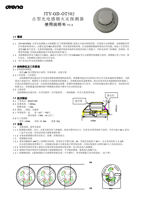
1.0 概述1.1 JTY-GD-OT502点型光电感烟火灾探测器(以下简称探测器)是我公司成功研制的新一代智能火灾探测器,该探测器采用红外散射原理设计,内置先进的MCU 微处理器,具有现场参数采集,自动检测探测器两端电压等功能,制造工艺采用先进的SMT 贴片技术。
完善的屏蔽措施,对电磁环境恶劣场所有着很好的抗干扰能力。
同时也采用了防潮湿、防腐蚀、防霉变等措施,对沿海高潮湿地区有着很好的防护能力。
1.2 该探测器采用电子编码方式编址,编址后与我公司生产的OZH4800等火灾报警控制器配合使用,探测器正常工作时,绿灯闪亮,当检测到火警信号时红灯常亮。
1.3 该产品为红外光电型感烟火灾探测器。
2.0 结构特征及工作原理2.1壳体材料和颜色采用ABS 复合塑胶设计成型,外观美观、安装方便.2.2工作原理、工作特性该探测器原理是通过红外光线传感器来测量烟的浓度的,探测器的迷宫在结构设计时红外光束是偏离传感器的。
当烟雾进入到迷宫内,烟雾粒子会将部分光束散射到传感器上。
若烟雾的浓度逐渐增加,就会有更多的光束被散射到传感器上。
在到达传感器的光束达到一定的程度探测器就会报警,报警时探测器指示灯常亮,并向控制器反馈火警信号,直到复位控制器为止。
控制器通过检测回路中探测器反馈的火警信号启动控制设备。
2.3 主要部件3.0 技术特征3.1 工作电压:DC20V-30V 3.2 监视电流: ≤350uA报警电流:≤2mA3.3 线制:二线制,无极性3.4 环境条件:温 度 -10℃~+50℃。
相对湿度 ≤95%(40±2℃)3.5尺寸及重量直径:100mm 高度:43.8mm 重量:82g4.0 安装4.1 安装基础、条件及要求4.1.1探测器对烟雾、灰尘、水雾及挥发性气体敏感,因此对那些灰尘大、经常有水雾等场所不适用;另外风速≥5m/s 的风口也不宜安装,因为这些地方烟雾很难积聚。
4.1.2 安装前探测器应保存在防尘、防潮、防霉的地方。
小时代502保护器说明书

小时代502保护器说明书① 设定电动机保护电流值:按“解锁设定”键3秒钟不放。
LED显示“30.0”(出厂设定保护电流值为30A)。
按“移位”键调整到所需要调整的位置,然后按“增加”键来设定所需要的值。
(设定范围0~99.9A)② 设定上电延时时间:再次按“解锁设定”键,LED显示“F00”(出厂设定上电延时时间为0秒),按“移位”键调整到所需要调整的位置,然后按“增加”键来设定所需要的值。
(设定范围0秒~99秒)③ 设定不平衡值:再次按“解锁设定”键,LED显示“H20”(出厂设定不平衡值为35%)然后按“增加”键来设定所需要的值。
(H00%,H20%,H35%任意选择)。
④ 查看设定值:长按“移位”键,分别显示已设定的保护电流值,上电延时,不平衡值,(按“查询”键切换各参数的查看)。
主要技术指标⑴ LED显示:在正常工作状态下循环显示三相电流值,切换间隔为3秒钟,精度±5%,在故障工作状态下循环锁定显示故障时的三相电流值,便于查找故障原因。
⑵ 不平衡保护:公式(*大值—*小值)÷*大值×*如:A相20A,B相25A,C相22A,不平衡值=(25-20)÷25×*=20% 当超过不平衡值20%时,保护器动作,断开负载。
若不平衡值选定H00,则默认关闭不平衡保护。
⑶ 缺相保护:当检测到缺相或三相严重不平衡并超过延时时限,保护电路动作,断开负载。
(当不平衡超过50%时就默认为缺相保护)⑷ 过载保护:当三相电流*大相电流超过设定电流值,保护电路动作,断开负载。
⑸ 相序保护:相序指相位的顺序,是三相电势到达*大值的先后次序叫做相序。
在某些设备中,相序不能接错,否则造成设备损坏。
当相序错误时,保护电路动作,断开负载。
⑹ 自动合闸:自动合闸间隔大约*钟,自动合闸次数3次⑺ 电源电压:AC220V±10%AC380V±10%⑻ 输出触点容量:5A/240V AC(纯阻性负载)⑼ 外形尺寸:宽×高×厚106mm×86。
爱国者数码伴侣王 U悦系列说明书

用户手册
公司简介
爱国者电子科技有限公司正式成立于2010年,前身是爱国者存储科技有限公司。公 司集产品研发、营销、服务为一体,提供数字产品与解决方案,其移动存储产品十年内 市场占有率第一。 公司首次提出“移动存储”概念,推出全球首款大容量移动存储产品;旗下录音笔 产品完成了神六、神七录音存储任务,并用于司法、教育等领域;硬盘产品拥有多项核 心技术及自主研发的专利,倍受行业瞩目;又推出国内首款平板电脑aigopad,为市场带 来新活力。此外,还涉及数码相框、多功能存储卡、网络存储、高清网络播放机、教育 电子等新兴产品与技术,被各界赞扬。 爱国者电子以成为业界一流国际化高科技企业为目标,坚持自主创新,必将实现民 族品牌的腾飞!
Version:1.0
2
用户手册
版权声明版权 本说明书的所有版权属于爱国者电子科技有限公司。 本说明书未经过爱国者电子科技有限公司明确的书面许可,任何人不得为任何其他目的、 以 任何形式或手段使用、复制或传播本说明书的任何部分。 本说明书对应产品上预装的操作系统和任何应用软件均受相关著作权法律法规、 国际公约以 及用户许可协议/条款的保护,仅许可您在其预装或所依附的硬件产品上使用,不得复制、 修改、编译、分发、分许可、出租或以其它方式转让或变相非法使用。 商标 爱国者相关标识是爱国者电子科技有限公司的注册商标; 其它公司的公司名称、 产品名称或 者服务名称也可能是其它公司的注册商标,无论是否在产品上或者本说明书中逐一注明 和 ® 标记,均受相关商标法律法规、国际公约的保护。
Version:1.0
3
用户手册
---带电插拔主机电源或其它附属设备 ---自行拆卸、修理、安装 ---自行性能升级 ---使用指定之外的零件、附属品、消耗品
YH502扭矩传感器说明书1

NO.2014-03 YH502系列扭矩传感器用户手册感谢您使用YH502系列扭矩传感器产品。
《用户手册》为正确的选用、安装、使用本产品作了必要的说明,请严格按照本手册指导使用。
一、应用范围:YH502系列扭矩传感器是一种测量各种扭矩、转速及机械功率的精密测量仪器。
应用范围十分广泛,主要用于:1、电动机、发动机、内燃机等旋转动力设备输出扭矩及功率的检测;2、风机、水泵、齿轮箱、扭力板手的扭矩及功率的检测;3、铁路机车、汽车、拖拉机、飞机、船舶、矿山机械中的扭矩及功率的检测;4、可用于污水处理系统中的扭矩及功率的检测;5、可用于制造粘度计;6、可用于过程工业和流程工业中。
二、基本原理:1、扭矩的测量:采用应变片电测技术,在弹性轴上组成应变桥,向应变桥提供电源即可测得该弹性轴受扭的电信号。
将该应变信号放大后,经过压/频转换,变成与扭应变成正比的频率信号。
如图所示:应用原理图2、转速的测量:转速测量采用磁电码盘的方法进行测量,每一磁电码盘均有60个齿,轴带动磁电码盘每旋转一周可产生60个脉冲,转速传感器精度可达±0.1%~±0.5%(F·S),本传感器的测速方法采用内置测速,订货时用户需注明是否监测转速信号!三、外形尺寸:尺寸参考下图:四、产品特征:1. 开机5分钟即可进入工作状态,勿需预热过程。
2. 检测精度高、稳定性好、抗干扰性强。
3. 不需反复调零即可连续测量正反扭矩。
4. 体积小、重量轻、易于安装。
5. 传感器可脱离二次仪表独立使用,直接输出与扭矩成正比的频率信号或模拟量。
五、主要性能及电气指标:扭矩精度:<±0.5 % F• S、<±0.25 % F• S、<±0.1 % F • S(可选)频率响应: 100μs非线性:<±0.1 % F• S重复性:<±0.1% F• S回差:<0.1 % F• S零点时漂:<0.2 % F• S零点温漂:<0.2 % F• S /10℃使用温度:-20 ~ 50℃储存温度:-40 ~ 70℃电源电压:±15VDC、24VDC(可选)信号输出: 5KHz—15KHz、0-20mA、4-20mA、0-5V、0-10V、1-5V (可选)六、传感器量程的选择扭矩传感器量程的选择应以实际测量的最大扭矩为依据,通常情况下应留有一定余量,防止出现过载导致传感器损坏。
星辰电器 STAR-MAX 电热平板 502Z 和 502FZ 型号 用户指南说明书
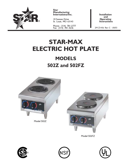
StarManufacturing Inter national Inc.10 Sunnen DriveSt. Louis, MO 63143Phone: (314) 781-2777Fax: (314) 781-3636Installation and Operating InstructionsSTAR-MAXELECTRIC HOT PLATEMODELS 502Z and 502FZ2M-Z1436 Rev. C 1/8/03Model 502ZModel 502FZThis symbol is intended to alert the user to the presence of important operating and maintenance instructions in the manual accompanying the appliance.RETAIN THIS MANUAL FOR FUTURE REFERENCENOTICEUsing any part other than genuine Star factory supplied parts relieves the manufacturer of all liability.NOTICEStar reserves the right to change specifications and product design without notice. Such revisions do not entitle the buyer to corre-sponding changes, improvements, additions or replacements for previously purchased equipment.MAINTENANCE AND REPAIRSContact your local authorized service agent for service or required maintenance. Refer to the authorized service center listing provided with the unit. The Star Service Help Desk (1-800-807-9054) is available during normal business hours to answer any questions that may arise. Please have your model number and serial number for faster service.SAFETY SYMBOLLOCATE THE UNITDo not install the unit closer than 1 inch from a side wall and/or closer than 1 inch from a rear wall.LEVELING UNITLevel unit by adjusting the (4) feet for accurate and perfect line up with other Star-Max series units.CAUTIONDO NOT INSTALL WITHOUT FEET.CAUTIONUSE ONLY FLAT BOTTOM PANS AND POTS! DO NOT USE RAISED BOTTOM UTENSILS OR BUCKETS! GOOD HEAT TRANSFER DEPENDS UPON GOOD CONTACT BETWEEN THE ELEMENT AND POT.Two (2) heating elements are used. For the 502FZ each element draws 2600 watts on 240 Volts and 1950 watts on 208 Volts. For the 502Z each element draws 2100 watts on 240 Volts and 1575 watts on 208Volts. Each element is controlled by an infinite position switch. The right control knob controls the rear cooking element and the left control knob controls the front cooking element. On "HI" the element delivers uninterrupted full heat. Between "LO" and "5"any desired amount of heat can be obtained between 6% and 60% of full heat.Signal lights are provided above the control knobs to give a visual check if either one or both heating units are turned on.CAUTIONThis equipment is designed and sold for commercial use only by personnel trained and experienced in its operation and is not sold for consumer use in and around the home nor for use directly by the general public in food service locations. For equipment to be used by the general public, please contact the factory.The Star-Max models 502Z and 502FZ Electric Hot Plates are equipped for the voltage indicated on the nameplate mounted on the front panel. This unit is designed to operate on alternating current (A.C.), two wire single phase service only. DO NOT CONNECT TO DIRECT CURRENT (D.C.).Total Connected Load502FZ - at 240 Volts, Wattage is 5200.at 208 Volts, Wattage is 3900.502Z - at 240 Volts, Wattage is 4200. at 208 Volts, Wattage is 3150.INSTALLATIONFor your protection, we recommend that a qualified electrician install this appliance. The electrician should be familiar with electrical installations and your local electrical requirements. The external wiring should be in conduit or an approved type of flexible cable and of suitable size to carry the load. The supply circuit should be properly fused and equipped with a means of disconnecting as required by local electrical code.The body of the hot plate should be grounded (Do not ground to a gas supply pipe). The connections are made in this unit at the pigtail leads located in the junction box on the back of the unit. To gain access to the pigtail leads remove cover on junction box.GENERAL OPERATING INSTRUCTIONSCLEANINGThe exterior surfaces can be kept clean and attractive by regularly wiping with a clean soft cloth. Any discoloration can be removed with a non-abrasive cleaner.For model 502Z, the heating elements may be raised for access to the drip pans, which may be removed for cleaning and the bottom pan may be removed by sliding pan forward.REPLACEMENT OF INFINITE CONTROL BE SURE POWER IS DISCONNECTED BEFORE ATTEMPTING TO SERVICE UNIT.1.Pull control knobs on front panel forward toremove.2.Remove 4 screws from front panel and tilt frontpanel forwards.3.Remove the nut that mounts the inoperativecontrol and pull the control to the side.4.Remove one wire at a time from the inoperativecontrol and connect at the same terminal on the new control. Carefully check to see that proper wires have been connected to the terminals of the control. See attached wiring diagram.5.Assemble new control to the front panel. MAINTENANCE AND REPAIRSContact the factory or one of its representatives or a local service company for service or maintenance if required.RETAIN THIS MANUAL FOR FUTURE REFERENCE Part No. 2M-Z1436 Rev. C 1/8/03The foregoing warranty is in lieu of any and all other warranties expressed or implied and constitutes the entire warranty.FOR ASSISTANCEShould you need any assistance regarding the Operation or Maintenance of any Star equipment; write, phone, fax or email our Service Department.In all correspondence mention the Model number and the Serial number of your unit, and the voltage or type of gas you are using.ALL:* Pop-Up Toasters * Butter Dispensers * Pretzel Merchandisers * Pastry Display Cabinets * Nacho Chip Merchandisers * Accessories of any kind * Sneeze Guards * Pizza Ovens * Heat Lamps * Hot Cups * PumpsVisit our Website at: Email: **********************************************:(800) 807-9814THOROUGHLY INSPECT YOUR UNIT ON ARRIVALThis unit has been tested for proper operation before leaving our plant to insure delivery of your unit in perfect condition. However, there are instances in which the unit may be damaged in transit. In the event you discover any type of damage to your product upon receipt, you must immediately contact the transportation company who delivered the item to you and initiate your claim with same. If this procedure is not followed, it may affect the warranty status of the unit.LIMITED EQUIPMENT WARRANTYAll workmanship and material in Star products have a one (1) year limited warranty on parts & labor in the United States and Canada. Such warranty is limited to the original purchaser only and shall be effective from the date the equipment is placed in service. Star's obligation under this warranty is limited to the repair of defects without charge, by the factory authorized service agency or one of its sub-agencies. Models that are considered portable (see below) should be taken to the closest Star service agency, transportation prepaid.>Star will not assume any responsibility for loss of revenue.>On all shipments outside the United States and Canada, see International Warranty.*The warranty period for the JetStar series six (6) ounce popcorn machines is two (2) years.*The warranty period for the Chrome-Max Griddles is five (5) years on the griddle surface. See detailed warranty provided with unit.* The warranty period for Teflon/Dura-Tec coatings is one year under normal use and reasonable care. This warranty does not apply if damage occurs to Teflon/Dura-Tec coatings from improper cleaning, maintenance, use of metallic utensils, or abrasive cleaners. This warranty does not apply to the “non-stick”properties of such materials.> This warranty does not apply to "Special Products" but to regular catalog items only. Star's warranty on "Special Products" is six (6) months on parts andninety (90) days on labor.> This warranty does not apply to any item that is disassembled or tampered with for any purpose other than repair by a Star Authorized Service Center or theService Center's sub-agency.> This warranty does not apply if damage occurs from improper installation, misuse, wrong voltage, wrong gas or operated contrary to the Installation and Operatinginstructions.>This warranty is not valid on Conveyor Ovens unless a "start-up/check-out" has been performed by a Factory Authorized Technician.PARTS WARRANTYParts that are sold to repair out of warranty equipment are warranted for ninety (90) days. The part only is warranted. Labor to replace the part is chargeable to the customer.SERVICES NOT COVERED BY WARRANTYPORTABLE EQUIPMENTStar will not honor service bills that include travel time and mileage charges for servicing any products considered "Portable" including items listed below. These products should be taken to the Service Agency for repair:1.Travel time and mileage rendered beyond the 50 mile radius limiteage and travel time on portable equipment (see below)bor to replace such items that can be replaced easily during a daily cleaning routine, ie; removable kettles on fryers, knobs, grease drawers on griddles, etc.4.Installation of equipment5.Damages due to improper installation6.Damages from abuse or misuse7.Operated contrary to the Operating and Installation Instructions 8.Cleaning of equipment 9.Seasoning of griddle plates10.Voltage conversions 11.Gas conversions12.Pilot light adjustment 13.Miscellaneous adjustments14.Thermostat calibration and by-pass adjustment 15.Resetting of circuit breakers or safety controls 16.Replacement of bulbs 17.Replacement of fuses18.Repair of damage created during transit, delivery, &installation OR created by acts of God* The Model 510F Fryer.* The Model 526TO Toaster Oven.* The Model J4R, 4 oz. Popcorn Machine.* The Model CFS Series Food Steamer.* The Model 526WO Warming Oven.* The Model 518CM & 526CM Cheese Melter.* The Model 12MC & 15MC & 18MCP Hot Food Merchandisers.* The Model 12NCPW & 15NCPW Nacho Chip/Popcorn Warmer.* All Hot Dog Equipment except Roller Grills & Drawer Bun Warmers.* All Nacho Cheese Warmers except Model 11WLA Series Nacho Cheese Warmer.* All Condiment Dispensers except the Model CSD & HPD Series Dispenser.* All Specialty Food Warmers except Model 130R, 500, 11RW Series, and 11WSA Series.PARTS LISTEFFECTIVEIMPORTANT: WHEN ORDERING, SPECIFY VOLTAGE OR TYPE GAS DESIREDPAGEINCLUDE MODEL AND SERIAL NUMBEROFSome items are included for illustrative purposes only and in certain instances may not be available.NumberPer UnitDescriptionPartNumberKeyNumberMODEL1/8/03 Rev. C 502Z Star-Max Electric Hot Plate12R-Z14312KNOB-THERMOSTAT 22M-Z63241FRON T GRAPHIC 3I3-Z63151FRON T PAN EL 42J-Y71142PILOT LIGHT52J-64032CON TROL-IN FIN ITE 240V 62C-99382ADAPTER-TERMINAL 72A-Z03144FOOT 4" DIE CAST 8I3-Y77081SLIDE, DRAWER 9I3-Y76941DRAWER10I3-5020101BACK WELD ASSEMBLY 11G3-Y77881COVER, HAN DY BOX 122C-Y23441TERMINAL-GROUND 132K-80434BUSHIN G - HEYCO #514I3-Y78222COVER-TERMIN AL BLOCK 152N-Y77792ELEMENT162D-64702PAN-REFLECTOR172P-64682RIN G-ELEMEN T ADAPTER 18I3-Y78914CHAIN STRAIN RELIEF19I3-5020201502Z, 502ZS WELD ASSEMBLY 20I3-6020041LIN ER ASSY RIGHT 21H3-Z13392SIDE (LEFT/RIGHT)22I3-5020161LIN ER ASSY LEFT23I3-6020051CEN TER AN GLE WELD ASSY 24I3-Y74031AN GLE, FRON T BOTTOM 25I3-Y74051AN GLE, TOP26I3-Y74631COVER CON TROL11PARTS LISTEFFECTIVEIMPORTANT: WHEN ORDERING, SPECIFY VOLTAGE OR TYPE GAS DESIREDPAGEINCLUDE MODEL AND SERIAL NUMBEROFSome items are included for illustrative purposes only and in certain instances may not be available.NumberPer UnitDescriptionPartNumberKeyNumberMODEL1/8/03 Rev. C 502FZ Star-Max Electric Hot Plate12R-14312KNOB-THERMOSTAT 22M-Z63241FRON T GRAPHIC 3I3-Z63151FRON T PAN EL 42J-Y71142PILOT LIGHT52J-64032CON TROL-IN FIN ITE 240V 62C-99382ADAPTER-TERMINAL 72A-Z03144FOOT 4" DIE CAST 8I3-5020101BACK WELD ASSEMBLY 9G3-Y77881COVER, HAN DY BOX 102C-Y23441TERMINAL-GROUND 112K-80434BUSHIN G-HEYCO #512I1-1621172CLAMP ASSEMBLY13I3-5020211502FZ TOP WELD ASSEMBLY 142N-Y33012ELEMENT15H3-Z13392SIDE (RIGHT/LEFT)16I3-5020161LIN ER ASSY LEFT 17I3-6020041LIN ER ASSY RIGHT18I3-6020051CEN TER AN GLE WELD ASSY 19I3-Y74031AN GLE FRON T BOTTOM 20I3-Y74051AN GLE, TOP21I3-Y74631COVER CON TROL 22I3-Y74811BOTTOM11。
ZH-2使用说明
ZH-2电力故障录波分析装置使用说明书武汉中元华电科技有限公司目录第1章系统功能及主要技术指标 (1)第2章系统结构与配置 (8)第3章装置操作指南 (11)第4章配线程序使用说明 (33)第5章安装与调试 (41)第6章装置的型号命名方法 (43)第7章定值设置原则和方法 (46)附录1 装置屏体布局图 (49)附录2 模拟量端子排配线表 (50)附录3 开关量端子排配线表 (51)附录4 装置电气方框图 (52)附录5 故障波形图 (53)Q/ZH.QW/02-04ZH-2电力故障录波分析装置使用说明书武汉中元华电科技有限公司1第1章系统功能及主要技术指标1.1 概述ZH-2电力故障录波分析装置是采用当今世界最先进的DSP技术、通讯技术并结合电力系统的最新发展开发出的具有自主知识产权的新一代多功能电力故障动态记录及分析装置,是一种功能全面、性能可靠、技术先进的电力故障动态记录与分析装置,适用于各种需要故障录波的场合。
1.2 装置特点1. 满足电力部部颁标准通过电力工业部电力设备及仪表质量检验测试中心检测,符合以下标准:《220~500KV电力系统故障动态记录技术准则》(DL/T553-94)《220~500KV电力系统故障动态记录装置检验测试要求》(DL/T663-1999)2. 集故障录波与测距、实时监测和电能质量分析为一体不定长动态录波和故障测距,测距精度优于2%;记录系统发生大扰动时的时刻:年、月、日、时、分、秒、毫秒;记录系统发生大扰动前后各输入量(电流、电压、高频、开关状态等)的变化过程;电力系统实时监测,可实时显示电压、电流波形及系统的有功/无功功率、相角;故障分析和电能质量分析;功角、相角测量;记录油温、压力等非电气量的变化;记录保护和其它自动装置的动作情况;连续慢扫描。
3. 模块化结构,硬件设计先进高速DSP,16位A/D,采样速率10kHz可调,谐波分辨率≤99次,开关事件分辨率≥0.1ms;前置机最大配置为5块DSP板,可接入80路模拟量,160路开关量,每块DSP 板可输入16路模拟量,32路开关量,DSP板可互换;采用扩展ISA总线和大容量双端口RAM,录波数据同步转存,可进行长时间录波;前置机存贮容量大,最大配置时有20Mb SRAM和160Mb固态盘;高速实时处理多种判据,1ms内完成所有通道的突变量的判启动工作;模拟通道零漂自适应,25℃时,额定值下的电流、电压波形采样精度优于±0.5%;前置机采用固态盘备份故障录波数据,掉电时,故障录波数据不丢失;采用新型电路结构和16000门大规模可编程逻辑器件,集成度高,抗干扰能力强,系统运行稳定。
兆庄变频器说明书

50.00
Pd005 最高操作频率
10.00~400.00 Hz
50.00
Pd006 中间频率
0.01~400.00 Hz
2.5
Pd007
最低频率
+12V
FC
多功能输出端子
FA
3A/250VAC
FB
3A/30VDC
DRV UPF DCM
AM
ACM
多功能输出端子 24V/100mA
数位频率输出端
0~10V/100MA
/100mA
注:P1-P 内部短接
DMA001143B~DMA003043B
5
温州兆庄自动化设备有限公司
(6)、配线注意事项
(1)主回路配线 ● 配线时,配线线径规格的选定,请依照电工法规的规定施行配线,以确保安全。 ● 电源配线最好请使用隔离线或线管,并将隔离层或线管两端接地。 ● 请务必在电源与输入端子(R.S.T)之间装空气断路器 NFB。
(5)、基本配线图
变频器配线部分,分为主回路和控制回路。用户可将外壳的盖子掀开,此时可看到主回 路端子和控制回路端子,用户必须依照下列的配线回路准确连接。
下图为 ZH600 出厂时的标准配线图
4
10K Ω 电流输入端
温州兆庄自动化设备有限公司
制动电阻
P
Pr
R
U
S
V
M
T
W
E
VR(+10V) VI ACM
的线圈内部将产生很高的 dV/dT,这对马达的层间绝缘将产生破坏,请改用变频器专 用的交流马达或加装电抗器于变频器侧。 ● 变频器与电机间距离较长时,请降低载波频率,因载波越大,其电缆上的高次谐波漏 电流越大,漏电流会对变频器及其他设备产生不利影响。
巴斯夫安固力 ECO 502 ap产品安全技术说明书

安全技术说明书页: 1/11 巴斯夫安全技术说明书按照GB/T 16483编制日期 / 本次修订: 30.05.2023版本: 8.0日期/上次修订: 16.03.2022上次版本: 7.2日期 / 首次编制: 11.01.2007产品: 安固力 ECO 502 apProduct: Acronal® ECO 502 ap(30397973/SDS_GEN_CN/ZH)印刷日期 03.09.20231. 化学品及企业标识安固力 ECO 502 apAcronal® ECO 502 ap推荐用途: 原料, 仅用于工业用途公司:巴斯夫(中国)有限公司中国上海浦东江心沙路300号邮政编码 200137电话: +86 21 20391000传真号: +86 21 20394800E-mail地址: **********************紧急联络信息:巴斯夫紧急热线中心(中国)+86 21 5861-1199巴斯夫紧急热线中心(国际):电话: +49 180 2273-112Company:BASF (China) Co., Ltd.300 Jiang Xin Sha RoadPu Dong Shanghai 200137, CHINA Telephone: +86 21 20391000Telefax number: +86 21 20394800E-mail address: ********************** Emergency information:Emergency Call Center (China):+86 21 5861-1199International emergency number: Telephone: +49 180 2273-1122. 危险性概述纯物质和混合物的分类:严重损伤/刺激眼睛: 分类2A对水环境的急性危害: 分类3巴斯夫安全技术说明书日期 / 本次修订: 30.05.2023版本: 8.0产品: 安固力 ECO 502 apProduct: Acronal® ECO 502 ap(30397973/SDS_GEN_CN/ZH)印刷日期 03.09.2023 标签要素和警示性说明:图形符号:警示词:警告危险性说明:H319造成严重眼刺激。
欧米加工程公司 HH502 数字温度计用户指南说明书

e-mail:**************For latest product manuals:HH502Digital ThermometerIt is the policy of OMEGA Engineering, Inc. to comply with all worldwide safety and EMC/EMI regulations that apply. OMEGA is constantly pursuing certification of its products to the European New Approach Directives. OMEGA will add the CE mark to every appropriate device upon certification.The information contained in this document is believed to be correct, but OMEGA accepts no liability for any errors it contains,and reserves the right to alter specifications without notice. Benelux:Managed by the United Kingdom OfficeToll-Free: 0800 099 3344TEL: +31 20 347 21 21FAX: +31 20 643 46 43e-mail:**************Czech Republic:Frystatska 184, 733 01 Karviná, Czech Republic Toll-Free: 0800-1-66342TEL: +420-59-6311899FAX: +420-59-6311114e-mail:*****************France:Managed by the United Kingdom OfficeToll-Free: 0800 466 342TEL: +33 (0) 161 37 29 00FAX: +33 (0) 130 57 54 27e-mail:**************Servicing Europe:U.S.A. and Canada:Sales Service: 1-800-826-6342/1-800-TC-OMEGA Customer Service: 1-800-622-2378/1-800-622-BESTEngineering Service: 1-800-872-9436/1-800-USA-WHEN U.S.A.:ISO 9001 Certified OMEGA Engineering, Inc.One Omega Drive, P.O. Box 4047Stamford, CT 06907-0047 USAToll-Free: 1-800-826-6342TEL: (203) 359-1660FAX: (203) 359-7700e-mail:**************Servicing North America:For immediate technical or application assistance:Mexico:En Español: 001 (203) 359-7803FAX: (001) 203-359-7807**************.mxe-mail:*****************Germany/Austria:Daimlerstrasse 26, D-75392 Deckenpfronn, Germany Toll-Free************TEL: +49 (0) 7059 9398-0FAX: +49 (0) 7056 9398-29e-mail:*************United Kingdom:ISO 9001 Certified OMEGA Engineering Ltd.One Omega Drive, River Bend Technology CentreNorthbank , Irlam, Manchester M44 5BD England Toll-Free: 0800-488-488TEL: +44 (0)161 777-6611FAX: +44 (0)161 777-6622e-mail:**************.uk Canada:976 Bergar Laval (Quebec), Canada H7L 5A1Toll-Free: 1-800-826-6342TEL: (514) 856-6928FAX: (514) 856-6886e-mail:*************INTRODUCTIONThis instrument is a 4½ digit, compact-sized portable digital thermometer designed to use external K-type and J-type thermocouples as temperature sensor. Temperature indication follows Reference Temperature/Voltage Tables (N.I.S.T. Monograph 175 Revised to ITS-90) for K-type and J-type thermo-couples. Two K-type thermocouple are supplied with the thermometer.SAFETY INFORMATIONIt is recommended that you read the safety and operation instructions before using the thermometer.WARNINGTo avoid electrical shock, do not use this instrument when working voltages at the measurement surface over 24V AC or DC.WARNINGTo avoid damage or burns, do not make temperaturemeasurement in microwave ovens.CAUTIONRepeated sharp flexing can break the thermocouple leads. To prolong lead life, avoid sharp bends in the leads, especially near the connector. The symbol on the instrument indicates that the operator must refer to an explanation in this manual.SPECIFICATIONSELECTRICALTemperature Scale: Celsius or Fahrenheit user-selectable. Measurement Range:J-TYPE -200°C to 1050°C, (-328°F to 1922°F)K-TYPE -200°C to 1370°C, (-328°F to 2498°F)Resolution: 0.1°C or 0.2°F.Accuracy: Accuracy is specified for operating temperatures over the range of 18°C to 28°C (64°F to 82°F), for 1 year, not including thermocouple error.±(0.05% rdg + 0.3°C) -50°C to 1370°C±(0.05% rdg + 0.7°C) -50°C to -200°C±(0.05% rdg + 0.6°F) -58°F to 2498°F±(0.05% rdg + 1.4°F) -58°F to -328°FTemperature Coefficient: 0.1 times the applicable accuracy specification per °C from 0°C to 18°C and 28°C to 50°C (32°F to 64°F and 82°F to 122°F). Input Protection: 24V dc or 24V ac rms maximum input voltage on any combination of input pins.Maximum Differential Common Mode Voltage (Maximum Voltage be-tween T1 and T2 during measurement): 1volt.Reading Rate: one time per second.Input Connector: Accepts SMP male miniature thermocouple connectors.ENVIRONMENTALAmbient Operating Ranges: 0°C to 50°C (32°F to 122°F) <80% R.H. Storage Temperature: -20°C to 60°C (-4°F to 140°F) <70% R.H. GENERALDisplay: 4½ digit liquid crystal display (LCD) with maximum reading of 19999. Overload: "----.-" is display.Battery: Standard 9V battery.Battery Life: 100 hours typical.Auto power off: The meter key switch inactive for more than 30 minutes, press power key to resume operation.Dimensions: 192mm(H) x 91mm(W) x 52.5mm(D).Weight: 365g.OPERATING INSTRUCTIONS Power SwitchThe key turns the thermometer on or off. In the data SET mode, can not power off, must leave data SET mode then power off.°C/°F Selecting the Temperature ScaleReadings are dual displayed in either degrees Celsius(°C) or degrees Fahrenheit(°F). When the thermometer is turned on, it is set to the temperature scale that was in use when the thermometer was last turned off. To change the temperature scale, press the °C/°F key.HOLD Mode (only Main display)Pressing the HOLD key to enter the Data Hold mode, the "HOLD" annun-ciator is displayed. When HOLD mode is selected, the thermometer held the present readings and stops all further measurements.Pressing the HOLD key again to cancel HOLD mode causing thermometer to resume taking measurements.In the MIN/MAX recording mode, press HOLD key to stop the recording.Press HOLD key again to resume recording. (Previously recorded reading are not erased).2314 5 6T1 /T2/T1-T2 Main display Input SelectionThe input selection indicates which input is selected for main display; T1 thermocouple, T2 thermocouple or the difference between the two thermo-couples (T1-T2), when the thermometer is turned on, it is set to T1, When main display input selected T1, then T1 input can select alternate of thermocouple by pressing K/J key switch.K/J T1 Input Thermocouple Type Select (Main display)The K/J key switch the T1 input selects the K-type or J-type thermocouple as input, when main display input selected T1.When the thermometer is turned on, it is set to the type selected that was in use when the thermometer was last turned off.MIN MAX with Time record Mode (only Main display)Press MIN MAX key to enter the MIN MAX Recording mode, (displays the Maximum reading with time, Minimum reading with time and Average reading stored in record mode). In the this mode the automatic power-off feature is disabled and key, °C/°F key, REL key, SET key, Hi/Lo LIMITS key and main display T1 T2 T1-T2 key, K/J key are disabled.The beeper emits a tone when a new minimum or maximum value is recorded.Push MIN MAX key to cycle through the MAX, MIN and AVG readings. If an overload is recorded, the averaging function is stopped and average value display"----.-".7In the this mode, press HOLD key to stop the recording of readings, all values are frozen, press again to restart recording.To prevent accidental loss of MIN, MAX and AVG data, in this mode can only be cancelled by pressing and hold down the MIN MAX key for 2 seconds to exit and erased recorded readings.WARNINGMIN, MAX and AVG readings can be recorded for a period of up to 20 hours maximum. If this 20 hours period is exceeded the unit readings will not be accurate.REL Relative mode (only Main display)Pressing REL key to enter the Relative mode, zero the display, and store the displayed Reading as a reference value and annunciator REL is displayed. Press REL key again to exit the relative mode.The relative value can also be entered by the user. (See "SET mode" later in this manual.)When the desired Relative value has been entered, press REL key to enter the Relative mode, press SET key use set Relative value as a reference value. Press REL key again to exit the relative mode.In the Relative mode, the value (can not >±3000.0 counts) shown on the LCD is always the difference between the stored reference and the present reading.8 9Sec. Minu. Selecting the Time scaleReading the third displayed (Time) in either second or minute. When the thermometer turned on, it is set to second. To change the Time scale, press sec. Minu. key.Maximum Time reading is 100 hours. If 100 hours is exceeded, reset Time to zero and restart.SET mode (Relative value set, Time set and Hi/Lo Limits value set)1. Press SET key to enter Relative valuse SET mode (Press ENTER key canescape relative valuse set mode), REL set mode. = = = =.= is displayed in main display.Relative value is entered via overlay numbers, then press overlay ENTER key, stored the relative value, enter Time set mode.2. Time set mode, (Press ENTER key can escape Time set mode)=.= = = : = = is displayed in second and third display. Time (hours, minutes, seconds) value is entered via overlay numbers, then press overlay ENTER key. Time start from set time value, enter Hi/Lo Limits value set mode. 3. Hi Limit value set mode, is displayed (Press ENTER key can escape HiLimit value set mode), = = = =.= is displayed in main display, Hi Limit value is entered via overlay numbers, then press overlay ENTER key, stored the Hi Limit value, enter Lo Limit value set mode (Press ENTER key can escape Lo Limit value set mode). = = = =.= is displayed in main display, Lo Limit value is entered via overlay numbers, then press overlay ENTER key, stored the Lo Limit value and exit SET mode.10114. When the thermometer is turned on. The Relative set value and Hi/Lo Limits set value that was in use when thermometer was last turned off set values.T1/T2/T1-T2 second display Input SelectionThe input selection indicates which input is selected for second display; T1thermocouple, T2 thermocouple or the difference between the two thermo-couples (T1-T2), when the thermometer is turn on, it is set to T2 input can select alternate of thermocouple by second display K/J key switch.K/J T2 Input thermocouple type select (second display)The K/J key switch the T2 input selects the K-type or J-type thermocouple as input, when second display input selected T2.When the thermometer is turned on, it is set to the type selected that was in use when the thermometer was last turned off.Hi/Lo Limits mode (only Main display)Press Hi/Lo Limits key to enter the Hi/Lo Limits comparative mode, is displayed, when input temperature value exceed Hi or Lo Limits value. The beeper emits a continuity pulse tone. Press Hi/Lo Limits key again to exit the Hi/Lo Limits mode.12OPERATOR MAINTENANCEWARNINGTo avoid possible electrical shock, disconnect the thermocoupleconnectors from the thermometer before removing the cover. Battery ReplacementPower is supplied by a 9 volt "transistor" battery. The "display when replacement is needed. To replace the battery, remove the two screws from the back of the meter and lift off the battery cover. Remove the battery from battery contacts.CALIBRATION PROCEDURENote: The following calibration procedures should be performed only by qualified technicians who have access to the following:Equipment: The class of calibration should be 10 times greater than the measured meter.Step 1: Short the J3 with jumper.Step 2: Apply 65 mV to the T1 input from Volts Calibrator and wait till the reading becomes stable, then press the SET key until the display shows 0.1.Step 3: Apply Type K 0°C to the input T2 and wait till the reading becomes stable, then press the SET key until the meter shuts off by itself.Step 4: Remove the jumper from J3.FOR WARRANTY RETURNS, please have the following information available BEFORE contacting OMEGA:1.Purchase Order number under which the product was PURCHASED,2.Model and serial number of the product under warranty,and3.Repair instructions and/or specific problems relative to the product.FOR NON-WARRANTY REPAIRS, consult OMEGA for current repair charges. Have the following information available BEFORE contacting OMEGA:1. Purchase Order number to cover the COST of the repair,2.Model and serial number of the product, and3.Repair instructions and/or specific problems relative to the product.OMEGA’s policy is to make running changes, not model changes, whenever an improvement is possible. This affords our customers the latest in technology and engineering. OMEGA is a registered trademark of OMEGA ENGINEERING, INC.© Copyright 2008 OMEGA ENGINEERING, INC. All rights reserved. This document may not be copied, photocopied, reproduced,translated, or reduced to any electronic medium or machine-readable form, in whole or in part, without the prior written consent WARRANTY/DISCLAIMEROMEGA ENGINEERING, INC. warrants this unit to be free of defects in materials and workmanship for a period of 13months from date of purchase. OMEGA’s WARRANTY adds an additional one (1) month grace period to the normal one (1) year product warranty to cover handling and shipping time. This ensures that OMEGA’s customers receive maximum coverage on each product.If the unit malfunctions, it must be returned to the factory for evaluation. OMEGA’s Customer Service Department will issue an Authorized Return (AR) number immediately upon phone or written request. Upon examination by OMEGA, if the unit is found to be defective, it will be repaired or replaced at no charge. OMEGA’s WARRANTY does not apply to defects resulting from any action of the purchaser, including but not limited to mishandling, improper interfacing,operation outside of design limits, improper repair, or unauthorized modification. This WARRANTY is VOID if the unit shows evidence of having been tampered with or shows evidence of having been damaged as a result of excessive corrosion; or current, heat, moisture or vibration; improper specification; misapplication; misuse or other operating conditions outside of OMEGA’s control. Components in which wear is not warranted, include but are not limited to contact points, fuses, and triacs.OMEGA is pleased to offer suggestions on the use of its various products. However, OMEGA neither assumes responsibility for any omissions or errors nor assumes liability for any damages that result from the use of its products in accordance with information provided by OMEGA, either verbal or written.OMEGA warrants only that the parts manufactured by the company will be as specified and free of defects.OMEGA MAKES NO OTHER W ARRANTIES OR REPRESENTATIONS OF ANY KIND W HATSOEVER,EXPRESSED OR IMPLIED, EXCEPT THAT OF TITLE, AND ALL IMPLIED W ARRANTIES INCLUDING ANY W ARRANTY OF MERCHANTABILITY AND FITNESS FOR A PARTICULAR PURPOSE ARE HEREBY DISCLAIMED. LIMITATION OF LIABILITY: The remedies of purchaser set forth herein are exclusive, and the total liability of OMEGA with respect to this order, whether based on contract, warranty, negligence,indemnification, strict liability or otherwise, shall not exceed the purchase price of the component upon which liability is based. In no event shall OMEGA be liable for consequential, incidental or special damages.CONDITIONS: Equipment sold by OMEGA is not intended to be used, nor shall it be used: (1) as a “Basic Component”under 10 CFR 21 (NRC), used in or with any nuclear installation or activity; or (2) in medical applications or used on humans. Should any Product(s) be used in or with any nuclear installation or activity, medical application, used on humans, or misused in any way, OMEGA assumes no responsibility as set forth in our basic WARRANTY/DISCLAIMER language, and, additionally, purchaser will indemnify OMEGA and hold OMEGA harmless from any liability or damage whatsoever arising out of the use of the Product(s) in such a manner.RETURN REQUESTS /INQUIRIESDirect all warranty and repair requests/inquiries to the OMEGA Customer Service Department. BEFORE RETURNING ANY PRODUCT (S) T O OMEGA, PURCHASER MUST OBT AIN AN AUT HORIZED RET URN (AR) NUMBER FROM OMEGA’S CUST OMER SERVICE DEPART MENT (IN ORDER T O AVOID PROCESSING DELAYS). T he assigned AR number should then be marked on the outside of the return package and on any correspondence. T he purchaser is responsible for shipping charges, freight, insurance and proper packaging to prevent breakage in transit.Where Do I Find Everything I Need for Process Measurement and Control?OMEGA…Of Course!Shop online at smM2807/1008TEMPERATUREⅪߜThermocouple, RTD & ThermistorProbes, Connectors, Panels & Assemblies ⅪߜWire: Thermocouple, RTD & Thermistor ⅪߜCalibrators & Ice Point References ⅪߜRecorders, Controllers & ProcessMonitors ⅪߜInfrared PyrometersPRESSURE, STRAIN AND FORCEⅪߜTransducers & Strain GagesⅪߜLoad Cells & Pressure Gages ⅪߜDisplacement Transducers ⅪߜInstrumentation & AccessoriesFLOW/LEVELⅪߜRotameters, Gas Mass Flowmeters &Flow Computers ⅪߜAir Velocity Indicators ⅪߜTurbine/Paddlewheel Systems ⅪߜTotalizers & Batch ControllerspH/CONDUCTIVITYⅪߜpH Electrodes, Testers & Accessories ⅪߜBenchtop/Laboratory Meters ⅪߜControllers, Calibrators, Simulators &Pumps ⅪߜIndustrial pH & Conductivity EquipmentDATA ACQUISITIONⅪߜData Acquisition & Engineering SoftwareⅪߜCommunications-Based AcquisitionSystems ⅪߜPlug-in Cards for Apple, IBM &Compatibles ⅪߜDatalogging Systems ⅪߜRecorders, Printers & PlottersHEATERSⅪߜHeating CableⅪߜCartridge & Strip Heaters ⅪߜImmersion & Band Heaters ⅪߜFlexible Heaters ⅪߜLaboratory HeatersENVIRONMENTALMONITORING AND CONTROLⅪߜMetering & Control InstrumentationⅪߜRefractometers ⅪߜPumps & TubingⅪߜAir, Soil & Water Monitors ⅪߜIndustrial Water & Wastewater Treatment ⅪߜpH, Conductivity & Dissolved OxygenInstruments。
- 1、下载文档前请自行甄别文档内容的完整性,平台不提供额外的编辑、内容补充、找答案等附加服务。
- 2、"仅部分预览"的文档,不可在线预览部分如存在完整性等问题,可反馈申请退款(可完整预览的文档不适用该条件!)。
- 3、如文档侵犯您的权益,请联系客服反馈,我们会尽快为您处理(人工客服工作时间:9:00-18:30)。
7.2. 装置的安装位置.............................................................................................................23
7.3. 投入及运行....................................................................................................................23
5.
工作状态指示 ................................................................................................. 18
5.1. 指示灯...........................................................................................................................18
准时间,除特殊注明者外,均为北京时间。 3) 时间同步系统 time synchronization system
能接收外部时间基准信号,并按照要求的时间准确度向外输出时间同步信号和时间信息的系统。 注:时间同步系统通常由主时钟、若干从时钟、时间信号传输介质组成。 4) 时间同步装置 time synchronising device 时间同步装置又称时钟装置,包括主时钟和从时钟。 5) 主时钟 master clock 能同时接收至少两种外部时间基准信号(其中一种应为无线时间基准信号),具有内部时间基准 (晶振或原子频标),按照要求的时间准确度向外输出时间同步信号和时间信息的装置。 6) 从时钟 slave clock 能同时接收主时钟通过有线传输方式发送的至少两路时间同步信号,具有内部时间基准(晶振 或原子频标),按照要求的时间准确度向外输出时间同步信号和时间信息的装置。 7) 时间报文 time message 包含时间信息和报头、报尾等标志信息的字符串。 8) 秒脉冲 1 pulse per second, 1PPS 一种时间基准信号,每秒一个脉冲。 9) 分脉冲 1 pulse per minute, 1PPM 一种时间基准信号,每分一个脉冲。 10) 时脉冲 1 pulse per hour, 1PPH 一种时间基准信号,每小时一个脉冲。 11) 时间准确度 time accuracy 时钟装置输出的时间与标准时间(如北京时间)的一致性程度。
9.4. 安全性...........................................................................................................................30
9.5. 装置的维修....................................................................................................................30
ZH-502 时间同步系统 说明书
武汉中元华电科技股份有限公司
Wuhan Zhongyuan Huadian Science & Technology Co., Ltd
历史记录
修改历史记录
序号 01 02
日期 2010.5.4 2010.9.25
修改情况 创建 修改,增加术语定义,选型表和应用举例
1.1. 术语和定义......................................................................................................................1
1.2.........................................................................................................2
3.
模块结构与设计................................................................................................ 7
3.1. 接收模块 .........................................................................................................................7
1
ZH-502 时间同步系统说明书
12) 时间同步准确度 time synchronization accuracy 经时间同步后,被授时时钟输出的时间与授时时钟输出的时间的一致性程度。
文档历史记录
版本号 1.0 1.1
签字 谢文勤 谢文勤
校阅历史记录
序号 01 02
日期 2010.5.4 2010.9.25
排版 审核
校对情况
签字 谢文勤 张文瑶
批准历史记录
序号 01 02
日期 2010.6.7 2010.9.26
批准情况 批准 批准
签字 张小波 张小波
I
文档历史记录
目录
1.
装置概述........................................................................................................... 1
I
ZH-502 时间同步系统说明书
1. 装置概述
1.1. 术语和定义
1) 协调世界时 universal time coordinated,UTC 以世界时作为时间初始基准,以原子时作为时间单元(s)基础的标准时间。
2) 北京时间 Beijing standard time,BST 我国的标准时间。 注:北京时间为东八时区的标准区时,比 UTC 早 8 h 整,即 BST = UTC + 8 h。本部分中的标
9.2. 时间信号的保持和切换..................................................................................................29
9.3. 可维修性 .......................................................................................................................29
5.2. LCD 显示 ......................................................................................................................18
6.
系统选型表 ..................................................................................................... 19
8.
应用举例......................................................................................................... 26
8.1. 基本式时间同步系统的组成...........................................................................................26
8.2. 主从式时间同步系统的组成...........................................................................................26
8.3. 主备式时间同步系统的组成...........................................................................................27
3.4. 输出模块 .........................................................................................................................8
4.
技术指标......................................................................................................... 15
3.2. CPU 模块 ........................................................................................................................8
3.3. 电源模块 .........................................................................................................................8
9.
装置的故障与维修 .......................................................................................... 29
