(安全生产)霍尼韦尔安全操作指南
Honeywell C简易操作指南PPT学习教案

Honeywell 238CP简易操作指南
二、有防区需要旁路的布防、撤防操作 1、布防操作:当我们设置的防区中某个防区有人正常
Honeywell C简易操作指南
会计学
1
Honeywell 238CP简易操作 指南
一、正常的布防、撤防操作
1、布防操作:对所有已设置的防区进行布防,在布防键 盘上按【xxxx】(设置的4位密码)【#】,这个时候就把所 有已设置防区布防了。此时布防键盘上的电源灯、布防灯和 准备灯会亮起,表示布防成功(同时键盘会有蜂鸣声,大约 响30秒-120秒不等,根据现场所设置的延时时间确定)。同 时在键盘上布防后必须在设定的延时时间内离开所有布防的 区域,否则会导致报警主机自动旁路而在有人触发防区时候 不报警。
2、然后再按[03][9][xxxx][*4][#]([xxxx]为新设置 的4位密码)。
3、在布防键盘上按[*][#],新密码就设置好了。 4、下次需要再次修改此密码的话,重复第1、2、3 步步骤重新设置布防撤防密码。
第3页/共5页
Honeywell 238CP简易操作指南
四、常用状态灯
1、主机正常通电,自检正常时候,报警主机未布防 的状态下,如果没有任何防区触发,此时布防键盘上电 源灯、准备灯和服务灯常亮。
活动,而其他防区需要进行布防时候,先在布防键盘上按 【旁路】【X】(需要旁路的防区号)【#】,这个时候就把 该防区旁路了,此时该防区有人入侵也不会报警,然后按 【xxxx】(设置的4位密码)【#】,这个时候就把其他没 有旁路的防区布防了。此时布防键盘上的电源灯和布防灯 会亮起,表示布防成功(同时键盘会有蜂鸣声,大约响30 秒-120秒不等,根据现场所设置的延时时间确定)。同时 在键盘上布防后必须在设定的延时时间内离开所有布防的 区域,否则会导致报警主机自动旁路而在有人触发防区时 候不报警。
CO测报仪(霍尼韦尔)使用说明
CO测报仪(霍尼韦尔)重要提示:●每天使用之前,应完成仪器的自检过程●可燃气体传感器的灵敏度会受到高浓度硫化物,卤素化合物,含硅化合物,以及含铅气体或蒸汽的影响,也叫“中毒”,应避免在以上的环境中使用仪器。
●仪器不能长时间在高浓度可燃气体的环境下使用,以免损坏可燃气体传感器,如果必须使用,则使用后必须进行标定,如传感器已经损坏,需要更换新的传感器才能重新使用。
●不要用有机溶液,肥皂或含硅的溶液清洗仪器,以免损坏传感器。
●不要让仪器直接或受到电或机械冲击,受到冲击后应对仪器进行自检或标定。
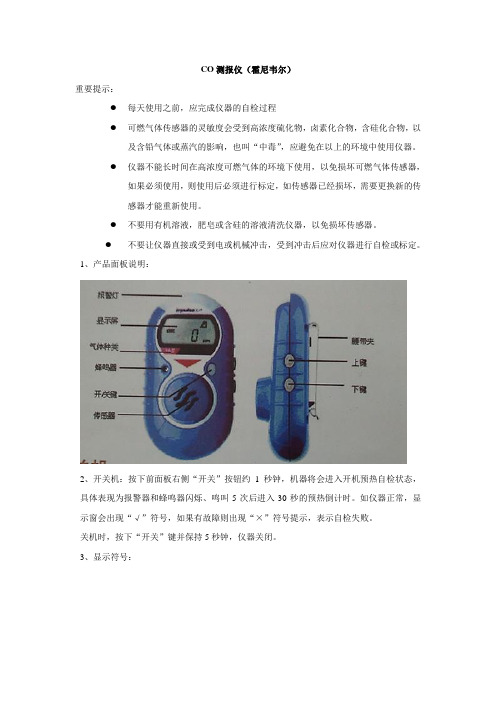
1、产品面板说明:2、开关机:按下前面板右侧“开关”按钮约1秒钟,机器将会进入开机预热自检状态,具体表现为报警器和蜂鸣器闪烁、鸣叫5次后进入30秒的预热倒计时。
如仪器正常,显示窗会出现“√”符号,如果有故障则出现“×”符号提示,表示自检失败。
关机时,按下“开关”键并保持5秒钟,仪器关闭。
3、显示符号:A:电池电量B:故障指示C:正常工作提示D:氧气和毒气一级报警信号毒气二级报警信号E:氧气二级报警信号F:毒气的TWA和STEL符号G:标定符号H:峰值符号I:浓度值和单位J:报警指示符4、安全自检过程:当按下开关键后,开机安全自检过程包括检查传感器,电路,电池,声/光报警以及振动报警。
厂家提醒用户在使用新的仪器时,用户最好让该仪器自检24小时。
1、电池欠压:如果仪器的电池欠压,则在屏幕上出现电池符号并同时闪烁,于此同时声光报警以每秒5次的频率激发,提示操作者更换电池。
2、报警解除:当所检测的气体超过报警点后,激发报警信号,其中︿表示毒气和氧气的一级报警符号,︽表示毒气的二级报警符号。
一旦报警发生,如果操作者确认该报警内容后且希望解除报警,只需按下“开关”、“上”或“下”键中的任意一个即可解除报警,并返回到正常操作模式。
霍尼韦尔说明书
霍尼韦尔说明书霍尼韦尔说明书简介霍尼韦尔(Honeywell)是一家全球领先的多元化科技和制造公司,总部位于美国,成立于1906年。
公司的业务涵盖航空航天、楼宇技术、性能材料、可持续性解决方案和安全解决方案等领域。
霍尼韦尔以其创新的技术、高品质的产品和可靠的性能享誉全球。
本文档旨在向用户提供关于霍尼韦尔产品的说明,并介绍如何正确使用和维护这些产品。
产品列表1. 霍尼韦尔智能温控器* 产品名称:霍尼韦尔智能温控器* 产品型号:TH9320WF5003* 产品特点:- 可与智能手机和智能家居系统连接,实现远程控制- 可编程设置温度和计划,提高能源效率- 大屏幕显示温度和湿度等信息* 使用说明:1. 将温控器与电源连接,并按照说明书设置温度和计划。
2. 下载并安装霍尼韦尔智能手机应用。
3. 打开应用,按照提示添加温控器设备。
4. 连接温控器和手机,即可实现远程控制。
2. 霍尼韦尔空气净化器* 产品名称:霍尼韦尔空气净化器* 产品型号:HFD-120-Q* 产品特点:- 高效过滤空气中的颗粒物和有害物质- 自动检测空气质量,并自动调整清洁模式- 低噪音设计,不影响正常生活* 使用说明:1. 将空气净化器放置在需要净化的房间内,并连接电源。
2. 按下电源开关,启动空气净化器。
3. 空气净化器将自动检测空气质量,并根据需要调整清洁模式。
4. 定期更换空气净化器中的滤网,以确保最佳的净化效果。
常见问题与解答Q1:为什么温控器无法连接智能手机?A:请确保智能手机和温控器处于相同的Wi-Fi网络下,并且已经下载并安装了霍尼韦尔智能手机应用。
如果问题仍然存在,请尝试重新连接温控器。
Q2:空气净化器何时需要更换滤网?A:根据使用环境和空气质量,滤网的寿命可能会有所不同。
一般建议每3至6个月更换一次滤网,或者根据空气净化器上的指示灯提示更换。
维护与保养为了保证霍尼韦尔产品的正常运行和延长使用寿命,以下是一些维护与保养的建议:1. 定期检查产品的电源和连接线,确保其无损坏和松动。
霍尼韦尔X4操作说明

X4的操作步骤
(1)、按住开/关键2秒钟,仪器开机
(2)、执行自检
接下来屏幕显示如下:
·显示一级报警点(可燃气和有毒气,氧气高浓度报警) ·显示二级报警点(可燃气和有毒气,氧气低浓度报警) ·显示STEL 和TWA 报警点(只对一氧化碳和硫化氢)
当按下开/关键后,仪器将检查传感器,电路,电池,声音,灯光,振动报警。
仪器将执行如下:(1)显示所有的数字和字符提示信息
(2)检查声音,灯光,振动报警 (3)检查电池,电路和传感器
(3)、自检是否通过
另外,仪器将会定期的检查电池,电路和传感器。
!注意:如果自检失败,应重新进行自检,如果再次失败请联系当地代理/服务商。
(4)、进入测量模式
(5)、解除报警
自检通过
正常显示
报警提示符号将
警符号(一级)
报警提示符号将
警符号(二级)
(6)、关机
修改报警值步骤
(1)、打开仪器至正常显示 (2)、同时按住上/下键,直到声音响起后松手
(3)、再按上键或下键选择到报警值界面 (4)、再按开关键,选择需要设置的气体
(5)、按上键或下键进行报警值的设置
(5)都设置完了,等20秒仪器自动回到检测模式
如何装电池。
霍尼韦尔 Honeywell安防系统安装和设置指南

4 系统操作 ................................................................................................................................. 42
4.1 安全密码 .......................................................................................................................... 42 4.2 紧急键.............................................................................................................................. 42 4.3 键盘功能 .......................................................................................................................... 43 4.4 报警声音通知(双向语音功能)...................................................................................... 44 4.5 “Follow Me”提示功能..................................................................................................... 45 4.6 “Follow Me”系统语音播放功能 ...................................................................................... 46 4.7 退出错误警报显示 ........................................................................................................... 46 4.8 故障情形 .......................................................................................................................... 46 4.9 测试模式 .......................................................................................................................... 47
霍尼韦尔DCS操作手册(通用)

霍尼韦尔PKS系统操作手册目录第一章.控制系统介绍 (3)1.Honeywell公司PKS系统概述 (3)2.我公司PKS系统配置 (4)第二章.过程操作 (5)1.画面介绍及操作 (5)1.1.标准画面介绍及操作 (5)1.2.状态行介绍(Unde rstanding the Status Line) (6)1.3.工具栏介绍(Using the Toolbar) (8)1.4.点细目画面及操作 (10)1.5.操作组画面及其操作 (20)1.6.报警功能及其画面操作 (22)1.7.信息摘要及其画面操作 (30)1.8.事件摘要及其画面操作 (32)1.9.警报摘要及其画面操作 (33)1.10.总貌画面 (34)1.11.用户流程图介绍 (34)2.历史数据和趋势操作 (37)2.1.历史数据: (37)2.2.趋势: (38)第一章. 控制系统介绍1.Honeywell公司PKS系统概述DCS系统采用霍尼韦尔的Experion PKS过程知识系统。
Experion PKS 系统是当代最先进的控制系统之一,包含了霍尼韦尔三十年来在过程控制、资产管理、行业知识等方面积累的经验,采用最先进的开放平台和网络技术,为工业企业提供一个统一的、全厂的、自动化过程控制、设备和资产管理、直至生产管理、集成制造等一体化的知识系统体系结构和全系列的解决方案。
Experion PKS系统能满足各种自动化应用要求,为过程控制、SCADA应用和批量控制提供一个开放式控制系统,且满足业界要求的高性能、灵活性、易用性、高可靠性等。
典型Experion PKS系统的体系结构如下图1所示。
图12.我公司PKS系统配置霍尼韦尔提供的系统覆盖范围包括中央控制室、6个现场机柜室,由提供的光纤网络以星形连接方式连接中央控制室和与其关联的各个现场机柜室。
网络图如下图2:图2硬件配置方面,霍尼韦尔公司为神达、昊达公司配置的是PKS系统最新版本R410,其配置如下:l控制器:Experion PKS系统的C300控制器作为DCS主控制器,性能强大,可以与多种IO卡件兼容。
霍尼韦尔净化器安全操作及保养规程
霍尼韦尔净化器安全操作及保养规程随着现代生活水平的不断提高,人们对生活环境的要求也越来越高。
在生活中,空气净化器被越来越多的人所使用。
霍尼韦尔净化器是一款高端的净化器,具有较高的净化效果和易于操作的特点。
下面,本文将介绍霍尼韦尔净化器的安全操作及保养规程,以帮助用户正确认识和使用净化器。
一、安全操作规程1.1 电源插头在插拔电源插头时应该始终保持手干燥,确定插头已连接到插座上,并确认插座电压与净化器电压相同。
同时,按下插头或插座上的开/关开关,并确保净化器已打开。
1.2 防火安全使用净化器时,不要在净化器附近放置易燃材料,并确保周围有足够空间进行通风。
除了推荐的滤芯和配件外,不要使用其他零部件。
1.3 禁止拆卸在使用净化器时,不要对净化器进行任何拆卸或维修操作。
不用时,将净化器从插座上拔下,并将其放在干燥,安全的地方。
1.4 离开房间如果需要暂时离开房间,建议将净化器关闭并拔掉电源插头。
如果长时间不使用净化器,建议将其开关置于“关闭”位置。
1.5 儿童和宠物将净化器放置在儿童和宠物无法触及的位置,并确保儿童和宠物无法拆卸净化器装置和零部件。
二、保养规程2.1 滤芯更换滤芯是净化器保持好效果的核心。
在使用中,应定期更换滤芯。
在贴有指示标签的滤芯上,记录滤芯使用时间和更换日期。
更换的周期大约为8-12个月。
在使用过程中,若出现滤芯破损、变形等情况,应及时更换。
2.2 机体清洁净化器外表面有灰尘,应使用干净、软布擦拭清洁,避免使用含清洁剂或酒精的清洁液。
同时,应严禁将薄膜覆盖在机体的表面。
2.3 机体检查不定期检查机体及插头是否有明显的损坏或磨损,确保净化器正常运行。
2.4 运输在搬运净化器时,应注意避免机体受到硬物或重压的冲击。
在安装时,避免在净化器身上施加过多的压力,以免机体和配件受到损坏。
三、总结霍尼韦尔净化器是一种高科技、高性能的净化器,具有卓越的净化效果和易于操作的特点。
然而,如果用户不能正确运用和维护它,则效果和使用寿命将大大降低。
霍尼韦尔安全操作及保养规程
霍尼韦尔安全操作及保养规程1. 前言霍尼韦尔(Honeywell)是一家知名的跨国集团公司,主要提供工业控制、民用航空、汽车产品和家庭安全等方面的产品和服务。
本文主要介绍了针对霍尼韦尔产品的安全操作和保养规程,以确保产品的正常使用和保证使用者的人身安全。
2. 规程2.1 安全操作规程2.1.1 聚氯乙烯(PVC)工艺操作•严格按照聚氯乙烯的相关操作规程进行操作,包括温度、压力、加热时间等方面的要求。
•避免直接与氯气接触,如出现漏气情况需及时拆除故障,避免爆炸和中毒。
•禁止直接接触硝酸,如需操作需穿戴防护用具。
如果硝酸泼溅到皮肤上,应立即用大量清水冲洗。
2.1.2 电子技术操作•操作电子产品时,应先按照产品说明书和相关规程了解产品使用方式和注意事项,避免误操作。
•在操作过程中,需要注意电源是否接地,防止触电事故发生。
2.1.3 压缩气体操作•压缩气体是具有爆炸性和毒性的危险品,作业时应当切实加强安全防范工作,如避免震动、撞击,防止气瓶急促受热等。
•禁止烟火近似气瓶存放和操作区域,禁止使用明火进行操作。
2.1.4 热处理操作•使用熔融盐进行热处理操作时,注意控制盐温、气氛和熔盐替换方式等操作,在漏盐事故发生后,应紧急切断电源,避免烧蚀。
•操作高温炉时,应戴防火手套和防护眼镜,防止烫伤和灼伤。
2.2 保养规程•对产品在使用过程中,应该及时进行日常保养和维护工作,确保产品的性能和稳定性。
•对于使用寿命较长的设备,在更换易损件时应选择质量可靠的配件或者使用原厂的配件,以确保产品能够长时间保持良好的工作状态。
•对于有特殊要求的产品,应按照产品说明书和相关规程进行保养和维护,以确保产品的使用寿命和安全性。
•在对产品进行保养和维护时,尽可能减少对相关零部件进行拆装和更换,以避免因操作不当造成设备损坏和事故的发生。
3. 结论本文主要介绍了针对霍尼韦尔产品的安全操作和保养规程,以确保产品的正常使用和保证使用者的人身安全。
霍尼韦尔自控面板操作说明举例
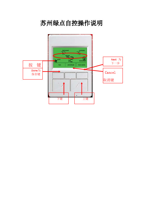
苏州绿点自控操作说明•面板对照表第一种类型UI1 MAU-201出风温度UI2 MAU-202出风温度UI5 MAU-201风车压差AO1 MAU-201冰水阀开度AO2 MAU-202冰水阀开度DI3 MAU-202风车压差Wsp_t1 MAU-201出风温度设定Wsp_t2 MAU-202出风温度设定Qh 冬夏切换第二种类型UI2 AHU-201回风温度UI3 2F末端水管压力AO1 AHU-201冰水阀开度AO2 AHU-201新风风门DI3 AHU-201风车压差DI4 AHU-201滤网压差Wsp_t1 AHU-201回风温度设定Qh 冬夏切换TR71面板操作说明面板显示点与接线表相对应例如:UI1:出风温度DI3:风车压差AO1:冰水阀开度AO1_DIS:冰水阀开度显示AO1_AM:与上述对应的手自动切换,“0”为自动,“1”为手动AO1_IN:与上述对应手动强制输入点Wsp_t1:出风温度设定值,可任意修改所需值以下为面板操作步骤:上述为主界面,按右边第一位,就可以进入显示屏上分3段,刚好底下有3个按键与此对应,从左到右依次为DONE,CANCEL,NEXT(确定,取消,下一步)按住NEXT,就可以看到这台控制器里面所有的点上述为UI1,继续点击NEXT,就能看到所有UI点对应的数据。
上述为DI1,显示风车的状态,故障和压差等,显示数值为“0”和“1”,“0”代表运行和正常,“1”代表停止与故障。
上述为阀体的开度显示点,AO1_DIS为蒸汽阀的开度显示上述为AO1冰水阀的手自动切换点,“0”代表蒸汽阀受程序自动控制,按照设计好的程序进行;“1”代表蒸汽阀不受程序控制,根据手动输入的值进行。
即“1”代表手动,“0”代表自动。
按面板上的上下键,就能修改数值。
上述为当AO1为手动强制输入之后的,AO1的强制输出值,通过上下键修改数值,之后按左上角的DONE键确认。
(0~100对应0~10V)上述为水泵和阀体的启停点,“0”代表停止,“1”代表启动。
霍尼韦尔氢气检测仪安全操作及保养规程

霍尼韦尔氢气检测仪安全操作及保养规程仪器简介
霍尼韦尔氢气检测仪是专门用于检测氢气浓度的仪器,其检测原理基于电化学传感器,可广泛用于氢燃料电池车、氢气气瓶、氢气发生器和实验室等领域。
安全操作
1.在操作前,必须保证仪器已充足充电或接入电源,并进行
自检后方可使用。
2.操作前要先查阅本使用手册,了解相关操作步骤及注意事
项。
3.打开仪器电源开关并等待一段时间后,待电池电量显示正
常后即可进行测量。
4.对于不同应用场景,选择不同的气体类型进行测量,如氢
气、氢气/二氧化碳。
5.检测仪的探头必须放置在测量范围内,根据测量需求选择
是否使用吸气管或延长探头。
6.检测时应尽量减少杂质干扰,如烟雾、污染物等。
7.检测过程中如发现异常情况,应立即停止操作并进行相关
维修或更换。
保养规程
1.使用完毕后,应关闭电源开关,尽量减少电池损耗。
2.检测仪使用后应定期进行维护及校准,建议一年一次或根
据使用频率进行调整。
3.检测仪外壳使用时应注意避免磨擦及碰撞,保持表面干净,
不使用时应放置于干燥通风处。
4.检测仪使用前应先查看是否有明显损坏或老化的零部件,
及时更换或修理。
5.电池使用寿命为2-3年,如发现电量衰减明显应及时更换
或充电。
6.探头使用寿命为12个月,如发现指示不准或无法读取应及
时更换探头。
7.请勿私自拆卸或改造检测仪,如需维修请联系相关售后服
务。
结语
以上就是霍尼韦尔氢气检测仪的安全操作及保养规程,使用者在使
用仪器时务必遵守相关规定,保证仪器的良好使用效果。
霍尼韦尔报警123VISTA120、250简易操作手册

霍尼韦尔报警123VISTA120、250简易操作手册VISTAR—120简易编程操作手册一、设置6160编程键盘开机后,键盘液晶屏幕无任何显示,此时同时按1 、3键5秒,键盘显示Con Addr=31或Addr=xx,输入00按*键盘绿灯亮,显示***DISARMED***READT TO ARM键盘地址不为00时,不能编程,6148键盘不能编程二、设置每个防区在撤防状态下,才能进入编程模式输入4140 8000(4140为出厂设置的安装员密码)进入编程模式,键盘显示:Program Mode*Fill # View按*93 键盘显示ZONE PROG?1=TES 0=NO输入0 1 0,进入防区编程模式,键盘显示:ZN ZT P RC IN L001 09 1 10 HW1 此处,ZN代表防区号;ZT代表防区类型01—出入口防区1型,布防时有延时,进入时有延时,延时时间由*09和*10设定;02—出入口防区2型,布防时有延时,进入时有延时,延时时间由*11和*12设定;03—周边防区,布防时有效,撤防时无效;06—24小时无声防区;07—24小时有声防区;09—火警防区;00—无用防区。
P代表子系统;RC代表报告码,系统默认即可,无需改动;IN代表防区输入类型,1-9防区统一为01,显示为HW;10防区以后统一为06,显示为SL;L 为回路号,除了是4193SN的第二回路为2,其他都为1。
例如:编程将24防区为24小时防区则在ZN下输入024 *(下一步)在ZT下输入24防区的防区类型07(24小时放区)在P 下输入24防区所属的子系统(部分区都为1)在IN下输入06**此时,键盘显示:024 INPUT S/N :LAxxx-xxxx :1此时输入24防区地址码输入完成后按*确认,在L处选择相应的回路再按*即进入下一方的。
退出防区编程:在防区号(ZN)处输入000 *1*99 即可退出编程注意:在防区编程状态下,*代表下一步,#代表返回。
霍尼韦尔安全操作指南

霍尼韦尔安全操作指南第一章日常维护第二章卡件改换第三章控制器第四章I/O卡件第五章罕见缺点第六章PID整定系统运用维护DCS系统是由系统软、硬件,操作台盘及现场仪表组成的。
系统中任一环节出现效果,均会招致系统局部功用失效或引发控制系统缺点,严重时会招致消费停车。
因此,要把构成控制系统的一切设备看成一个全体,停止片面维护管理。
1.1日常维护1.1.1机柜室管理应增强机柜室人员和设备管理。
为保证系统运转在适当条件下,请遵守以下各项:1)密封一切能够引入灰尘、潮气和鼠害或其它有害昆虫的走线孔〔坑〕等;2)保证空调设备动摇运转,保证室温变化小于+5℃/h,防止由于温度、湿度急剧变化招致在系统设备上的凝露;3)现场与控制室合理隔离,防止现场灰尘进入控制室,同时控制室定时清扫,坚持清洁。
4)进入机房、工程师室作业人员严厉遵守各项规章制度,进出须换鞋或带鞋套,不得将污物、食品、饮料等带入机房;保护机房、工程师室内设备,坚持机房、工程师室整洁;进入机柜间应封锁手机。
5)进程控制计算机机柜间内制止运用无线对讲设备。
6)技术组片面担任进程控制计算机的管理,各班组担任进程控制计算机机房、工程师室的日常卫生和日常维护任务。
工程师室内计算机及网络设备的维修由技术组成员担任,班组配合。
技术组成员在维修完设备后应做好设备规格化任务。
7)日光灯完整、灭火器按期反省、室内卫生整洁、操作台〔柜〕、主机外部、显示器、打印机等卫生清洁、打印机不缺纸、机柜内设备如机柜过滤网清洁、风扇完整,机、其他未明白但属于共有的设备等完整。
8)布线层的槽盒盖可以不盖,但应依据规格大小整洁地放置在空中上。
布线层墙壁、电缆进线口应密封,无人时,电灯只保管一组常亮。
9)室内施工管理:本班的设备施任务业由本班完成,外委作业时由本班派人监护〔包括剖析、检修等任务触及更改电源时〕。
施工完毕后应做到工完料净场地清,负有管理责任的班组应及时向对方班组指出施任务业后的室内卫生等效果。
霍尼韦尔 Honeywell安防系统快速指南
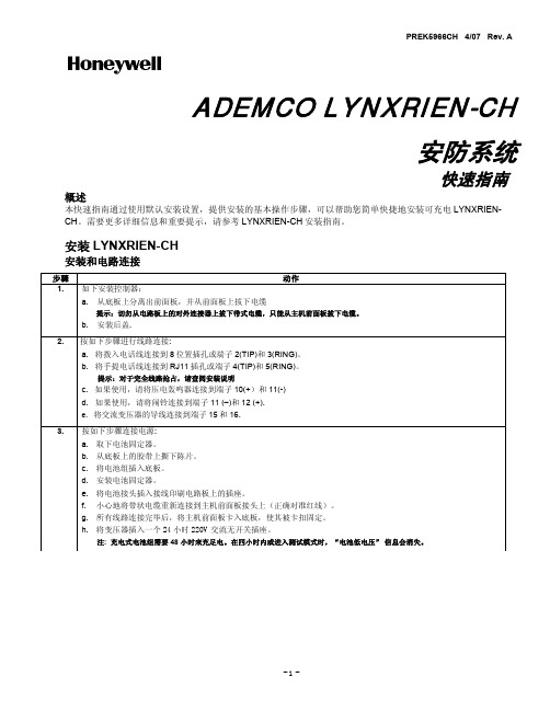
PREK5966CH 4/07 Rev. AADEMCO LYNXRIEN-CH安防系统快速指南 概述本快速指南通过使用默认安装设置,提供安装的基本操作步骤,可以帮助您简单快捷地安装可充电LYNXRIEN-CH。
需要更多详细信息和重要提示,请参考LYNXRIEN-CH安装指南。
安装LYNXRIEN-CH安装和电路连接步骤动作1. 如下安装控制器:a. 从底板上分离出前面板,并从前面板上拔下电缆提示:切勿从电路板上的对外连接器上拔下带式电缆,只能从主机前面板拔下电缆。
b. 安装后盖.2. 按如下步骤进行线路连接:a. 将拨入电话线连接到8位置插孔或端子2(TIP)和3(RING)。
b. 将手提电话线连接到RJ11插孔或端子4(TIP)和5(RING)。
提示:对于完全线路抢占,请查阅安装说明c. 如果使用,请将压电轰鸣器连接到端子10(+)和11(-)d. 如果使用,请将闹铃连接到端子11 (–)和12 (+).e. 将交流变压器的导线连接到端子15和16.3. 按如下步骤连接电源:a. 取下电池固定器。
b. 从底板上的胶带上撕下陈片。
c. 将电池组插入底板。
d. 安装电池固定器。
e. 将电池接头插入接线印刷电路板上的插座。
f. 小心地将带状电缆重新连接到主机前面板接头上(正确对准红线)。
g. 所有线路连接完毕后,将主机前面板卡入底板,使其被卡扣固定。
h. 将变压器插入一个 24 小时 220V交流无开关插座。
注: 充电式电池组需要 48 小时来充足电。
在四小时内或进入测试模式时,“电池低电压”信息会消失。
LYNXRIEN-CH 线路连接系统编程步骤动作1. 按如下步骤设置编程默认值:a. 进入编程模式: 安装人员代码 + 8 0 0。
b. 按*97,然后按1-4中一位数字,从LYNXRIEN-CH 设置默认值表中选择默认值。
2. 按如下步骤设置可变数据字段:a. RF 住宅ID代码 – 按 *24, 然后输入无线键盘需要的两位RF住宅ID。
霍尼韦尔用户手册-普通

3.1 基本组件.................................................................................................................................................. 3
自动火灾报警系统典型的组成包括:感烟探测器、 感温探测器、手报、告警设备和具有远程通知能力的 火灾报警控制设备,它能提供早期的火灾报警。一个 系统不能确保火灾发生时的生命及财产安全。
尽管火灾报警系统为早期火灾报警而设,但它不 能确保预报准确或防止火灾。由于各种原因,火灾报 警系统可能不能提供及时或适当的告警,甚至不能工 作。
为了确认其操作没有受到修改的影响必须对至少10最多50台的触发设备这些设备通常不会受到其它组件修改的影响也进行测试系统的运行必须正常
RP-1002PLUS 火灾报警控制器 气体灭火控制器
用户手册
版本:G 日期:2009-03-19
火灾报警系统的局限性
火灾报警系统能降低保险费用,但它不能替代火灾保险!
象所有的固态电子装置那样,当受到雷电感应的瞬间, 该系统可能运行紊乱或者被损害。虽然没有系统能够完全 免除雷电感应或干扰,正确的接地将降低敏感系数。由于 会增加对附近雷击的易感性,不推荐使用高架的或户外的 天线。如果预计或遇到任何问题,请向技术性服务部门资 讯。
在拆除或者插入电路板之前应断开交流电和电池,否 则会损坏电路。
霍尼韦尔国标防坠器安全操作及保养规程
霍尼韦尔国标防坠器安全操作及保养规程前言霍尼韦尔国标防坠器作为一种个人安全保护设备,能够提供防止从高处坠落的功能,是众多高空作业人员不可或缺的设备。
但是如果不注意使用方法和保养维护,可能会带来安全隐患。
因此,本文将介绍霍尼韦尔国标防坠器的安全操作及保养规程,以确保用户能够在使用过程中避免危险,保证人身安全。
安全操作规程1. 穿戴前检查在使用防坠器之前,应进行以下检查以确保防坠器的正常使用: •检查防坠器上是否有严重的刮嗒、裂痕或其他损伤。
•检查所有的位置绳、吊环、旋转扣及其他连接装置,确保其都没有松动或断裂。
•检查安全带是否完好无损,并确认正确佩戴方式。
2. 确认稳定安全点在使用防坠器之前,应确保使用点稳定强固,以避免因使用点不稳定而导致的危险。
确保使用点能够承受额定荷重。
3. 开始使用前的准备工作在开始使用防坠器之前,应先对防坠器进行正确操作,以确保存在任何问题。
当然,对于新着使用者,及时请教专业人员操作。
4. 正确使用防坠器在使用防坠器时,请注意以下事项:•检查防坠器是否已正确连接并完全展开。
•保持身体的平衡和稳定。
•避免和其他人或物体碰撞。
•避免突然的跨步或停顿,以减小意外发生的可能性。
5. 安全下降操作进行下降操作时,应遵守以下操作程序:•首先,请确认自身安全带已正确佩戴。
•在进行下降操作前,请确保所有连接装置已经正确接好,且安全。
•如果发现任何不正常的情况,请立即停止下降操作。
6. 停止下降操作当您到达目的地时,请进行以下操作:•处理连接装置,确保其安全;•确认安全带正常佩戴;•检查防坠器是否受损并进行保养。
以上内容均为使用时的基本操作须知,请严格按操作流程进行。
保养规程为了保障霍尼韦尔国标防坠器的正常使用寿命,以下是一些保养要求:1. 每次使用前的检查进行每次使用前的检查时,要特别注意以下情况:•检查防坠器的外观是否有严重的刮嗒、裂痕或其他损伤情况。
•检查防坠器的功能是否正常。
•检查各连接处,是否松动或连接不良2. 每年的检查要求批量使用的防坠器每年都要进行一次维护和检查。
霍尼韦尔气体灭火控制器操作流程

霍尼韦尔气体灭火控制器操作流程下载温馨提示:该文档是我店铺精心编制而成,希望大家下载以后,能够帮助大家解决实际的问题。
文档下载后可定制随意修改,请根据实际需要进行相应的调整和使用,谢谢!并且,本店铺为大家提供各种各样类型的实用资料,如教育随笔、日记赏析、句子摘抄、古诗大全、经典美文、话题作文、工作总结、词语解析、文案摘录、其他资料等等,如想了解不同资料格式和写法,敬请关注!Download tips: This document is carefully compiled by theeditor.I hope that after you download them,they can help yousolve practical problems. The document can be customized andmodified after downloading,please adjust and use it according toactual needs, thank you!In addition, our shop provides you with various types ofpractical materials,such as educational essays, diaryappreciation,sentence excerpts,ancient poems,classic articles,topic composition,work summary,word parsing,copy excerpts,other materials and so on,want to know different data formats andwriting methods,please pay attention!霍尼韦尔气体灭火控制器操作指南霍尼韦尔作为全球知名的楼宇自动化和安全系统的供应商,其气体灭火控制器以其高效可靠而广受信赖。
Honeywell 安全指南:掌握重型工业工作场所的手保护标准说明书

TECHNICAL GUIDE Understanding Key Hand Protection Standardsfor Heavy-Duty Industrial WorkplacesHand ProtectionIntroductionFrom operating complex machinery to handling hazardous substances, workers in industrial workplaces are particularly vulnerable to hand injuries. It’s a far-reaching problem that affects worksites across the globe. In the United States, hand injuries are consistently #1 on the list of recordable incidents each year for industries like oil and gas.1 These incidents add up – compounding the problem with lost time and profits. Over 3.2 million workplace accidents resulted in lost time for workers in the European Union during 2015.2This technical guide will highlight several of the most common – but avoidable – risks to worker safety, as well as the impact of these riskson company productivity. Health and safety managers will learn about recent and upcoming changes to regulations and standards for personal protective equipment (PPE), and how to select the right hand protection for the unique needs of their environment and tasks.Knowing and understanding how to comply with these standards and regulations are key to ensuring that workers in highly dangerous environments are able to perform their jobs effectively while remaining safe and healthy.4 5 6 7 8 9 10 11 13 14 15The causes and costs of hand-related injury The hazardsThe costsThe choicesHand protection standardsEN 388ANSI 105ISEA 138EN 420EN 511ConclusionTable of contentsThe causes and costs of hand-related injury When it comes to risk reduction on industrial worksites you need a full hierarchy of controls: from the perspective of both engineering and administration, as well as the selection of personal protective equipment (PPE), each level plays an important role in mitigating hand injuries. That’s critical because in heavy-duty environments there is no shortage of hazards that can injure unprotected hands. With 27 separate bones articulated by a complex web of tendons, ligaments, muscles and nerves, the hand is as precisely engineered as any tool on the job. It’s this incredible precision that makes hands so adept at complicated tasks – and so vulnerable to injury.This vulnerability makes consistently wearing hand protection a top safety priority. 70% of U.S. workers who’ve injured their hands on the job weren’t wearing gloves at the time.3 As many as 20 amputations, 180 fractures and 455 lacerations each year result from being caught in, or struck by tools or similar machinery.4 That’s what makes hands the fifth most common occupational injury, according to theBureau of Labor Statistics.The world over, hands are your workers’ most vital and vulnerable tool. Understanding the hazards workers encounter is the first step to keeping them safe.of U.S. workers whoinjured their handsWEREN’T WEARINGG LOVES.3The types and sources of hand injuries may be more prevalent than you realize. The threat of smashes and pinches is present wherever heavy tools or materials are being handled. According to a US Department of Labor study, injuries to fingers and hands accounted for more than 23% of all injuries reported, making them the highest in preventable injuries and in terms of lost work days.4 A less obvious impact on hand health is vibration from equipment like jackhammers, drills or even sledgehammers, which can lead to compromised grip strength over mon building materials such as glass, metal and wood can result in cuts and slices when not handled correctly. The tools workers use – box cutters, knives, punch presses and other edged machinery – also come with the potential for danger. A wide array of common industrial materials can result in abrasions from slings and wire ropes, nails and screws, even steel shims or scrap metal. Punctures can be large wounds caused by objects like wood slivers or metal burrs, but they can also result from smaller materials, such as frayed wires. The latter often go unnoticed or neglected, which can lead to infection. There’s also the risk of lacerations, which usually start as punctures, dragging and then tearing the skin as the hand makes contact. Together, cuts and punctures account for 47% of hand injuries in the U.S.5The hazards23%of all injuries reported were tofingers and hands.447%of hand injuries are cuts and punctures.5OtherSorenessHeat BurnsAmputationSprains/StrainsSmash/PinchCut/Puncture543The costs No matter the cause, when injuries occur on the job everyone pays the price. According to the Bureau of Labor Statistics and the National Safety Council, the financial toll of the 186,830 hand injuries reported in the U.S. during 2012 had an average cost of $21,918 per injury. That price tag includes medical costs and indemnity but does not factor in the loss of time. Hand injuries combined for over 100 million days lost in the U.S. during 2016. Many workers go on to require rehabilitation, an additional investment of time that varies greatly based on the severity of the injury. An additional 55 million additional days are projected to be lost in future years due to injuries from 2016.6 In some cases, workers never regain adequate hand function, which effectively ends their career. This also results in the loss of years of experience when they exit the workforce.Across Europe, hand injury payouts are as common as they are costly. Moderate hand injuries involving cuts and crushes in the U.K. during 2018 led to settlements ranging between £800 and £3,800. In extreme cases, such as amputations, the cost can reach as high as £177,000 for pain and suffering.8All together, The National Safety Council estimates that the financial cost of work-related deathand injuries in 2016 totaled up to $151.1 billion when factoring in income not received or ex-penses incurred. 9$21,918 average cost per injury.7$151.1BILLIONspent in 2016 on workplace injuries.9The choicesThe negative impact of hand injuries is apparent. The right solution, less so. Heavier-gauge gloves offer greater hand protection against cut and abrasion injuries, while thinner ones provide more dexterity and tactile sensitivity. For gloves intended to be worn all day, prioritizing comfort becomes vital. In cold weather or around molten metals, insulation becomes a deciding factor. And let’s not forget enhanced grip for slippery objects, or chemical protection for dangerous substances. There is so much to consider. It’s critical to assess the unique hazards of each worksite, whether they be cuts, abrasions, chemical exposure or extreme temperatures. Personal protection equipment is crucial in any safety program and has been proven to reduce the risk of hand injury by as much as 60%.7Health and safety managers have more choices than ever when it comes to PPE for hands. Much of this is due to advances in technology and the development of new materials. Manufacturers now produce a wide range of gloves – each with unique characteristics and advantages – to protect workers in a variety of high-risk industries. From this abundance of choice arises complexity and with it a need for a baseline of performance and reliability.The absence of any comprehensive performance standard makes evaluating and comparing the impact protection of similar products difficult. As managers try to balance correctly equipping their workers with the need to stay cost-effective, ambiguity around how a glove will meet the needs of the job becomes a dangerous gamble.There is no one-size-fits-all solution for hand protection. However, when paired with a thoroughunderstanding of the latest hand protection standards, proper glove selection can be a valuable way to create a safer workplace, bolster employee morale and help increase overall productivity.Hand protection standardsIn both the U.S. and Europe, existing standards for industrial gloves have addressed cuts, abrasion, punctures and chemical exposure. Impact injuries, to which the back of the hand is particularly vulnerable, only recently became included in that standardization; first with Europe establishing guidelines in 2016, and the U.S. now following suit.The American National Standards Institute (ANSI) administers and coordinates the U.S. voluntary standards and conformity assessment system. The International Safety Equipment Association (ISEA), which is accredited by ANSI, works with manufacturers, test labs, subject matter experts, end-users and government agencies in the standards development process. The results of each test are assigned a rating that can be found printed on the glove.EN 388: 2016 Protective Gloves Against Mechanical Risks (European Standard)The EN 388: 2016 standard relates to gloves providing protection against mechanical risks: abrasion, Arraycutting, tearing and puncture, and an option for impact-resistance. To meet this standard, gloves must pass a series of tests against these risks:1. A brasion tests are usually carried out in a Martindale Abrasion Tester, where samples are cut from the palms of gloves and are subjected to rubbing against glass paper until a sample wears and a hole appears. The performance of the sample is measured as the number of abrasion rubs before sample breakthrough, from Level 1, which is awarded if the sample can withstand up to 100 rubs, to Level 4, where the accepted limit is 8000 rubs. The achieved level of abrasion resistance is indicated on the glove. Recent changes to this test have resulted from the change of specification of the abradant paper.2. C ut resistance testing equipment, such as the TDM-100 that’s used for EN ISO 13997 standardization, is specially designed for testing gloves. It involves lowering a horizontal blade onto a clamped sample of the glove material and then passing this blade back and forth across the sample until penetration occurs. The number of cycles of the rotating blade is used to determine the cut index, which ranges from Level 1, indicating one or two cycles, to Level 5, indicating 20 cycles.T here have been recent changes to this test method (known as the Coupe test), to mitigate the effect of dulling of the test blade. The new TDM-100 test, according to EN ISO 13997, is applied to mate-rials prone to blunting the blade, and gloves are now rated from A to F as shown in the table below. Gloves tested using the Coupe test are marked 1 to 4 and, in addition to that, those which have been subjected to the new test are marked A to F. All gloves from Level 4, according to the Coupe test, must also be tested to EN ISO 13997. Honeywell already exceeds these requirements as all gloves from Level 3 undergo this test.Honeywell EN 388 guide, according to the EN ISO 13997 TDM cut test method:3. T ear resistance tests are carried out by clamping a sample of material in the jaws of a strength testing machine and measuring, in newtons, the force required to tear the material. Gloves tested for tear resistance are then marked from 1 to 4, where 1 indicates a tearing force of 10 newtons and 4 indicates a force of 75 newtons.4. P uncture resistance tests are based on the amount of force, in newtons, required to pierce a sample with a standard-sized point. Again, gloves are rated from 1 to 4 and this is indicated on the glove.5. I mpact, an optional test EN13594:2015, is adapted from protection standards for motorcycle gloves, which focuses on impact-resistant features added to the back of the hand or the knuckles. It is performed by dropping a 2.5kg weight that lands with 5 joules of force on the glove. The letter “P” is the new rating mark added to gloves that have passed.ANSI-105: 2016 revision (U.S.) protective gloves against mechanical risks. ANSI / ISEA 2016 is the latest revision to the voluntary industry standard used to help workers understand classifications that assist employers and product users in the selection of gloves for specific workplace exposures. The major change surrounds classification for cut resistance.Why update the standard? The old system had a disparate gap among the higher-level ratings. The newly updated standardincludes additional classification levels to correct this. There was also a need to model the approach used in similar international guidelines.What’s been updated?There are now nine levels of classification. See below comparison table of how the restructured ANSI cut levels compare to the previous ones. In order to limit the confusion of the old classifications to the current one, an “A” has been added. As an example, if a glove is classified as cut-level 1 using the updated standard, the glove would be rated an ANSI level A1 for cut protectionANSIA 6Cutnew levelsANSI/ISEA 138: New Impact Protection (U.S.)ISEA is made up of the leading PPE manufacturers, including glove manufacturers, as well as other safety product suppliers.ISEA 138, the American national standard for performance and classification for impact-resistant hand protection, aims to improve on the fairly limited treatment of impact performance recently incorporated into the main European hand protection standard, EN 388. That standard took its cues from an existing motorcycle impact standard for hand protection. The ISEA 138 standard, by contrast, is specifically designed for industrial gloves and the special protection they offer to workers. The proposed ISEA 138 standard will, for the first time in the United States, provide industry-accepted test criteria to measure how effectively different dorsal impact protective gloves reduce peak impact force across the hand. The ANSI/ISEA 138 standard’s stated scope is to establish “minimum performance, classification and labelling requirements for hand protection products designed to protect the knuckles and fingers from impact forces, while performing occupational tasks.”It aims to evaluate compliant gloves “for their capability to dissipate impact forces on the knuckles and fingers” and to classify them accordingly. “The resulting classifications can be used by employers as a reliable means of comparing different products on an equal basis when selecting hand protection relative to the tasks being performed.”There are three performance levels specified by the standard, which offer a numerical representation for the impact protection a glove will offer, with the lowest protection offered by level one and the highest by level three. Under the standard, a higher performance level indicates a greater degree of protection.Both EN 388 and ANSI/ISEA 138 use essentially the same test method, but there are key differences between the two:• E N 388 is a pass/fail result, while ANSI/ISEA 138 incorporates three performance levels, giving greater choice and flexibility to the end user.• E N 388 only covers knuckles, but ANSI/ISEA 138 will cover knuckles and fingers, which is critical for industrial glove users where the fingers are frequently at risk.ANSI / ISEA 1383EN 420: General requirements and test methods for protective gloves (European Standard)All protective gloves, no matter what their specific protection function, must comply with EN 420. This standard ensures that the glove materials are tested so that they don’t put the workers that have to wear them at risk. Specifically:• The pH of the gloves should be as close as possible to neutral.• Leather gloves should have a pH value between 3.5 and 9.5.• The highest permitted value for chromium is 3mg/kg.• They should be sized by reference to an agreed common European hand size.• If gloves have seams, they should not reduce their performance.• N atural rubber gloves should be tested on extractable proteins to ensure they do not cause allergic reactions.• F or reusable gloves, the level of performance should not be reduced even after the maximum number of washes.All relevant information, in line with the PPE regulations described above, should also be displayed on the glove packaging. Only when the requirements for EN 420 have been met can gloves progress to testing to meet other, more specific standards. As the EN 420 does not cover the protective properties of gloves,it should never be applied in isolation, but only in combination with the relevant specific standards.EN 511: Protective gloves against cold (European Standard)The pictogram for gloves providing protection against cold carries three digits. The first digit shows resistance to convective cold (0 to 4). The second digit shows resistance to contact cold (0 to 4) and the third digit shows permeability to water (0 or 1, where 0 signifies water penetration after 30 minutesand 1 means no water penetration after 30 minutes).0-4Cold Resistance to convective cold0-4Resistance tocontact cold0-1Permeabilityto waterConclusionSince hand injuries are one of the most common injuries in many tough industrial environments, safety standards are continuously changing. And with the introduction of new heavy-duty equipment and better safety technologies, the standards often get more strict with each iteration. Keeping compliant can be difficult and expensive if you are not prepared. That’s why when sourcing PPE for your workers, it’s good to choose a partner who is constantly investing in design, technological research and user experience, and can help you stay ahead of safety legislation and will provide cutting-edge equipment that will help keep your workers safer.Honeywell is innovating for safety.Keep up with the latest information atABOUT HONEYWELLHoneywell Safety and Productivity Solutions (SPS), which incorporates Honeywell Industrial Safety, provides products, software and connected solutions that improve productivity, workplace safety and asset performance for our customers across the globe. We deliver on this promise through industry-leading mobile devices, software, cloud technology and automation solutions, the broadest range of personal protective equipment and gas detection technology, and custom-engineered sensors, switches and controls. We also manufacture and sell a broad portfolio of footwear for work, play and outdoor activities, including XtraTuf and Muck Boot brand footwear. For more news and information on Honeywell Safety and Productivity Solutions, please visit /newsroom. For more information on Honeywell's personal protective equipment offering visit .Honeywell () is a Fortune 100 software-industrial company that delivers industry-specific solutions that include aerospace and automotive products and services;control technologies for buildings, homes and industry; and performance materials globally. Our technologies help everything from aircraft cars, homes and buildings, manufacturing plants, supply chains, and workers become more connected to make our world smarter, safer and more sustainable.”References1G allaway Safety & Supply (2014) “Infographic: Hand Safety and Glove Guidelines for the Oil and Gas Industry”/infographic-hand-safety-glove-guidelines-oil-gas-industry/2E urostat Statistics Explained (2018) “Accidents at Work Statistics”https://ec.europa.eu/eurostat/statistics-explained/index.php/Accidents_at_work_statistics3I SHN (2015) “70% of workers who injure their hands aren’t wearing gloves”https:///articles/101332-ofworkers-who-injure-theirhands-arent-wearinggloves 4C DC (2014) “Maintenance and repair injuries in US mining.”https:///niosh/nioshtic-2/20044086.html5N ationalsafety’s Weblog (2018) “Hand Protection”/category/hand-protection66C DC/NIOSH (2014) “Maintenance and repair injuries in US mining.”https:///niosh/nioshtic-2/20044086.html7O H&S (2015) “Avoiding the Statistics: What You Can Do to Avoid the Thousands of Hand Injuries in the Oil and Gas Industry” https:///webcasts/2015/07/avoiding-the-statistics.aspx 8A ccident Claim Solicitors (2018) “Hand Injury Claims: UK accident solicitor sets out how muchcompensation you can claim for minor tor severe injuries to your hands”https:///compensation-amounts/hand-injury-claims.html9N ational Safety Council (2016) “Injury Facts: Work Injury Costs”https:///work/costs/work-injury-costs/For more informationHoneywell Industrial Safety9680 Old Bailes Rd,Fort Mill, SC 29707, USA800.430.5490***************************。
霍尼韦尔 伏卡安全系统 B208 八路输入模块操作指南说明书
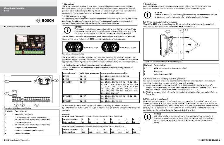
Callout Description1Heartbeat LED (blue)2SDI2 interconnect wiring connectors(to control panel or additional modules) 3SDI2 terminal strip(to control panel or additional modules) 4Tamper switch connector5Terminal connector (point inputs)6Address switches 1 OverviewThe B208 Octo-input Module is an 8 point supervised expansion device that connectsto control panels through the SDI2 bus. This module communicates back to the controlpanel all point status changes. The inputs are accessed through on-board screw terminalconnections. The on-board switches are used to specify module addresses.2 SDI2 address settingsTwo address switches determine the address for the B208 Octo-input Module. The controlpanel uses the address for communications. The address also determines the pointnumbers. Use a slotted screwdriver to set the two address switches.2.1 Valid addresses and point numbers per control panelValid B208 addresses are dependent on the number of points allowed by a particularcontrol panel.3 InstallationAfter you set the address switches for the proper address, install the B208 in theenclosure and then wire the module to the control panel and to the inputs.Control panel Valid B208 addresses Corresponding point numbersB551201 - 0411 - 18, 21 - 28, 31 - 38, 41 - 48B451201 - 0211 - 18, 21 - 28D9412GV401 - 2411 - 18, 21 - 28, 31 - 38, 41 - 48, 51 - 58,61 - 68, 71 - 78, 81 - 88, 91 - 98, 101 - 108,111 - 118, 121 - 127, 131 - 138, 141 - 148,151 - 158, 161 - 168, 171 - 178, 181 - 188,191 - 198, 201 - 208, 211 - 218, 221 - 228,231 - 238, 241 - 247D7412GV401 - 0711 - 18, 21 - 28, 31 - 38, 41 - 48, 51 - 58,61 - 68, 71 - 75D7212GV401 - 0311 - 18, 21 - 28, 31 - 38Figure 2.1: Address switchesTo determine the point numbers for each address, multiply the address numberby 10 for the base number, and then use numbers 1 through 8 in the ones place for the pointnumbers.ExamplesFor B208 address 01the point numbers for the input devices are 11 through 18:Terminal numbers12345678Point numbers1112131415161718For B208 address 11 the point numbers for the input devices are 111 through 118:Terminal numbers12345678Point numbers111112113114115116117118= Inputs 11 to 18= Inputs 111 to 118Set the address switches per the control panel confi guration. If multiple B208 modulesreside on the same system, each B208 module must have a unique address.NOTICE!The module reads the address switch setting only during power up. If youchange the switches after you apply power to the module, you must cyclethe power to the module in order for the new setting to be enabled.The B208 address switches provide a tens and ones value for the module’s address. Forsingle-digit address numbers 1 through 9, set the tens switch to 0 and the ones digit to theappropriate number. Figure 2.1 shows the address switches setting for addresses 9 and 11.3.1 Mount the module in the enclosureMount the B208 into the enclosure’s 3-hole mounting pattern using the suppliedmounting screws and mounting bracket. Refer to Figure 3.1.3.2 Mount and wire the tamper switch (optional)You can connect an enclosure door tamper switch for one module in an enclosure.Installing the optional tamper switch for use with a B208:1. Mount the ICP-EZTS Tamper Switch (P/N: F01U009269) into the enclosure’stamper switch mounting location. For complete instructions, refer to EZTS Coverand Wall Tamper Switch Installation Guide (P/N: F01U003734).2. Plug the tamper switch wire onto the module’s tamper switch connector. Refer toFigure 1.1.3.3 Wire to the control panelWhen you wire a B208 to a control panel, you can use either the module’s terminal striplabeled with PWR, A, B, and COM, or the module’s interconnect wiring connectors (wireincluded). Interconnect wiring parallels the PWR, A, B, and COM terminals on the terminalstrip. Figure 1.1 indicates the location of both the terminal strip and the interconnectconnectors on the module. Refer to Figures 3.2, 3.3, and 3.4.NOTICE!Use either the terminal strip wiring or interconnect wiring connector tothe control panel. Do not use both. When connecting multiple modules,you can combine terminal strip and interconnect wiring connectors inseries.Callout Description1B208 with mounting bracket installed2Enclosure3Mounting screws (3)Figure 1.1: B208 Octo-input Module NOTICE!Remove all power (AC and Battery) before making any connections. Failure to do so may result in personal injury and/or equipment damage.Callout Description1B208 Octo-input Module 2B208 sensor loops31 k Ω EOL resistor (ICP-1K22AWG-10)4Wiring to additional sensor loops3.4 Sensor Loop WiringWire resistance on each sensor loop must be less than 100 Ω with the detection devices connected. The terminal strip supports 12 to 22 AWG (0.65 to 2 mm) wires.The B208 detects open, short, normal, and ground fault circuit conditions on its sensor loops and transmits the conditions to the control panel. Each sensor loop is assigned a point number and transmits to the control panel individually. Run wires away from the premises telephone and AC wiring. Refer to Figure 3.5.4 LED descriptionsThe B208 Octo-input Module includes one blue heartbeat LED to indicate that the module has power and to indicate the module’s current state. Refer(GV4 Series control panel shown)Callout Description1Bosch control panel 2B208 Octo-input ModulesCallout Description1Bosch control panel 2B208 Octo-input Modules(GV4 Series control panel shown)(GV4 Series control panel shown)Callout Description1Terminal strip wiring (SDI2)2Interconnect cable (P/N: F01U079745) (included)Dimensions 2.5 in x 3.8 in x 0.60 in (63.75 mm x 96 mm x 15.25 mm)Voltage (operating)12 V nominal Current (maximum)35 mAOperating temperature +32°F to +122°F (0°C to +50°C)Relative humidity 5% to 93% at +90°F (+32°C) non-condensingLoop inputsUp to eight inputs. Input contacts may be Normally Open (NO) orNormally Closed (NC) with 1k Ω EOL resistor(s) for supervision. NOTICE: Normally Closed (NC) is not permitted in Fire installations.Loop End-of-Line (EOL) resistance1k ΩLoop wiring resistance 100 Ω maximum Loop statesShort: 0 - 1.1 VDCNormal: 1.25 - 1.9 VDC Open: 2.25 - 5 VDCTerminal wire size 12 AWG to 22 AWG (2 mm to 0.65 mm)SDI2 wiringMaximum distance - Wire size (Unshielded wire only): 1000 ft (305 m) - 22 AWG (0.65 mm)1000 ft (305 m) - 18 AWG (2 mm)CompatibilityB5512 (Up to 4 modules)B4512 (Up to 2 modules)D9412GV4 (Up to 24 modules)D7412GV4 (Up to 7 modules)D7212GV4 (Up to 3 modules)7 Speci fi cationsCopyrightThis document is the intellectual property of Bosch Security Systems, Inc. and is protected by copyright. All rights reserved.TrademarksAll hardware and software product names used in this document are likely to be registered trademarks and must be treated accordingly.Determine Bosch Security Systems, Inc. product manufacturing datesUse the serial number located on the product label and refer to the Bosch Security Systems, Inc. web site at /datecodes/.RegionUSUL 365 - Police Station Connected Burglar Alarm Units and Systems UL 609 - Local Burglar Alarm Units and Systems UL 985 - Household Fire Warning System Units UL 1076 - Proprietary Burglar Alarm Units and Systems UL 1023 - Household Burglar-Alarm System Units UL 1610 - Central-Station Burglar-Alarm UnitsUL 864 - Control Units and Accessories for Fire Alarm Systems CSFM - California Of fi ce of The State Fire Marshal FCC Part 15 Class B FM Approval 3010CanadaCAN/ULC-S304 Central and Monitoring Station Burglar Alarm Units ULC/ORD-C1023 Household Burglar Alarm System Units CAN/ULC-S303 Local Burglar Alarm Units and Systems ULC/ORD-C1076 Proprietary Burglar Alarm Units and Systems6 Certi fi cationsFlashing patterns do not start until the tamper is open (short is removed). The following is an example: The version 1.4.3 would be shown as LED fl ashes:[3 second pause] *___****___*** [3 second pause, then normal operation].When the tamper switch is activated (closed to open), the heartbeat LED stays OFF for 3 sec before indicating the fi rmware version. The LED pulses the major, minor, and micro digits of the fi rmware version, with a 1 sec pause after each digit.5 Show the fi rmware versionTo show the fi rmware version using an LED fl ash pattern: - If the optional tamper switch is installed:With the enclosure door open, activate the tamper switch (push and release the switch).- If the optional tamper switch is NOT installed: Momentarily short the tamper pins.。
Honeywell 电子PW系列控制器安全指南说明书

Honeywell Commercial Security715 Peachtree St.NEAtlanta, GA 30308August 30, 2022To whom it may concern;The following information is provided in response to requests on CIP information on PW Series Controllers, parts PW6K1IC, PW6K1ICE, and PW7K1IC.CIP-007 R1PW-Series Controllers protect against the use of unnecessary physical input/output ports used for network connectivity, console commands or removable media. Port usage is as follows:CIP-007 R2.1There have been no security patches related to PW series Controller firmware issued in the past. However, we reserve the right to do so in the future should it be required. All updates to date provided to the Controller firmware have served to provide additional functionality or modifications to existing functionality. None of these updates are classified as security issues. Any generated patches would be referenced in the monthly Patch Management Letter. Release notes are available upon request on new firmware releases.CIP-007 R2.2A monthly Patch Release Letter is provided upon request via email.CIP-007 R3.1The PW Series controllers are implemented as a single body executable file developed for a dedicated embedded application. They are not capable of accepting any external programs for execution (useful or otherwise). Therefore, the PW series controllers do not require virus protection software running on the controller. Any updates in Malicious Code prevention will be included in the monthly Patch Release Letter.CIP-007 R4.1, R4.2, R4.3The PW Series 7000 Controllers are capable of logging events related to cyber security incidents that at a minimuminclude detected successful login attempts, detected failed access attempts and failed login attempts.CIP-007 R4.2The PW Series Controllers are not capable of generating alerts for security events that include detected malicious code and detected failure of event logging.CIP-007 R4.3The PW Series Controllers are not capable of retaining applicable event logs.CIP-007 R5.1, R5.2, R5.5The PW6K11C and PW7K1IC have the following default accounts:Username: adminPassword:passwordThe admin user account on PW-Series Controllers is only enabled if DIP switch 1 is set to on. To disable default account access, follow this recommended process –1. Log on to the Controller from the web interface with the default admin account.2. Create a new admin user with a complex password.3. Turn off DIP switch 1.The Controller should be in a secure location to prevent unauthorized access to the DIP settings.Web access to the Controller can be disabled by turning the feature off on the Users screen of the web interface and setting DIP switch 1 to off.Note - If no users have been created then the default account will work regardless SW1. Once at least one user account has been created then the default account will only work with SW1 on. The option for disabling the web server is only enabled when you are logged on and SW1 is on. You will need to have SW1 ON, log on, set this option, log out, and then turn SW1 OFF.The Controllers have three password Strength levelsLow Password Strength – minimum of 6 charactersMedium Password Strength – minimum of 6 characters and passes two of the password strength tests below.High Password Strength – minimum of 8 characters, passes three of the password strength tests below, andpassword not based on user name.Password Strength Tests – contains characters from any of the following categories:Uppercase alphabet characters (A–Z)Lowercase alphabet characters (a–z)Arabic numerals (0–9)Symbol characters (`! $ ? ^ * ( ) _ - + = { [ } ] : ; @ ' ~ # | < , > . /)"The Maximum Password length is 10 characters.The Controllers are not capable of technically enforcing password length, complexity requirements, or required annual password changes.CIP-007 R5.7The PW Series Controllers are not capable of monitoring system events related to cyber security. The Controllers are not capable of issuing automated or manual alerts for detected cyber security incidents. The controller cannot issue an alert based on unsuccessful login attempts. The Controller will lock out a web login after 3 invalid login attempts for 1 minute.CIP-009 R1.5The PW Series Controllers are not capable of monitoring system events related to cyber security. In the event of a Cyber Security Incident, standard Server backup and recovery procedures would apply to the PACS system to be followed if necessary, by a reset and download of the PW Series Controllers.Respectfully,Sheeladitya KarmakarSr. Offering Manager**********************************。
霍尼韦尔T9275A操作说明

霍尼韦尔T9275A操作说明1、开机前请确认接线及24电源2、第一次送电LCD显示OFF(有DIGIT IN)或OPEN(无DIGIT IN),有DIGIT IN时按SELECT键3秒后开机,进入操作使用状态,若无DIGIT IN,请确认是否将DI短路。
3、开机后按UP或DOWN键,可设定温度1℃(连续按2秒,连续快速变化)按ENTER键一次,数字闪烁表示完成。
4、按SELECT键,选取其他功能再按UP或DOWN更改,再按ENTER 键即存储。
5、按SELECT键至SENSOR显示,0表示内置传感器,1表示外置传感器。
予设为0。
6、按SELECT键至MODE显示:予设为0。
0AO为制冷工况,DO×1AO为加热工况,DO×2AO为制冷工况,DO为加热工况3AO为加热工况,DO为制冷工况4AO为制冷工况,DO为LOW TEMP.LIMIT5AO为加热工况,DO为HIGH TEMP.LIMIT7、按SELECT键至MANUAL显示,0表示自动控制,1表示手动输出控制(0-100%)。
予设为0。
8、按SELECT键至DISPLAY显示,0表示LCD上方显示环境温度,下方显示设定温度,1表示LCD上方显示输出百分比,下方显示环境温度。
予设为0。
9、按SELECT键至F1显示(积分时间)予设为15秒,范围:0.1-60秒。
10、按SELECT键至F1显示(高低温报警)予设为30℃,(SENSOR 0时,10-60℃)(SENSOR 1时,-20-110℃)。
11、按SELECT键至OFFSET显示(温度补偿校正)予设为0℃,范围:-3℃-+3℃。
12、按SELECT键至P BAND显示(比例带),予设为2℃,范围:2℃-19℃。
13、按SELECT键至DIFF显示(动作偏差),予设为0℃,范围:0℃-3℃,同时使用制冷及加热(电热)时,其中一点DO控制时,可设定DIFFERENTIAL VALUE使温度控制于偏差范围内。
- 1、下载文档前请自行甄别文档内容的完整性,平台不提供额外的编辑、内容补充、找答案等附加服务。
- 2、"仅部分预览"的文档,不可在线预览部分如存在完整性等问题,可反馈申请退款(可完整预览的文档不适用该条件!)。
- 3、如文档侵犯您的权益,请联系客服反馈,我们会尽快为您处理(人工客服工作时间:9:00-18:30)。
(安全生产)霍尼韦尔安全
操作指南
HoneywellPKS系统维护手册
第一章日常维护
第二章卡件更换
第三章控制器
第四章I/O卡件
第五章常见故障
第六章PID整定
系统使用维护
DCS系统是由系统软、硬件,操作台盘及现场仪表组成的。
系统中任一环节出现问题,均会导致系统部分功能失效或引发控制系统故障,严重时会导致生产停车。
因此,要把构成控制系统的所有设备看成一个整体,进行全面维护管理。
1.1日常维护
1.1.1机柜室管理
应加强机柜室人员和设备管理。
为保证系统运行在适当条件下,请遵守以下各项:
1)密封所有可能引入灰尘、潮气和鼠害或其它有害昆虫的走线孔(坑)等;
2)保证空调设备稳定运行,保证室温变化小于+5℃/h,避免由于温度、湿度急剧变化导致在系统设备上的凝露;
3)现场与控制室合理隔离,避免现场灰尘进入控制室,同时控制室定时清扫,保持清洁。
4)进入机房、工程师室作业人员严格遵守各项规章制度,进出须换鞋或带鞋套,不得将污物、食品、饮料等带入机房;爱护机房、工程师室内设备,保持机房、工程师室整洁;进入机柜间应关闭手机。
5)过程控制计算机机柜间内禁止使用无线对讲设备。
6)技术组全面负责过程控制计算机的管理,各班组负责过程控制计算机机房、工程师室的日常卫生和日常维护工作。
工程师室内计算机及网络设备的维修由技术组成员负责,班组配合。
技术组成员在维修完设备后应做好设备规格化工作。
7)日光灯完好、灭火器按期检查、室内卫生整洁、操作台(柜)、主机外部、显示器、打印机等卫生清洁、打印机不缺纸、机柜内设备如机柜过滤网清洁、风扇完好,电话机、其他未明确但属于共有的设备等完好。
8)布线层的槽盒盖可以不盖,但应根据规格大小整洁地放置在地面上。
布线层墙壁、电缆进线口应密封,无人时,电灯只保留一组常亮。
9)室内施工管理:本班的设备施工作业由本班完成,外委作业时由本班派人监护(包括分析、检修等工作涉及更改电源时)。
施工结束后应做到工完料净场地清,负有管理责任的班组应及时向对方班组指出施工作业后的室内卫生等问题。
1.1.2操作站硬件管理
1)文明操作,爱护设备,保持清洁,防灰防水;
2)严禁擅自改装、拆装机器;
3)键盘与鼠标操作须用力恰当,轻拿轻放,避免尖锐物刮伤表面;
4)尽量避免电磁场对显示器的干扰,避免移动运行中的工控机、显示器等,避免拉动或碰伤设备连接电缆和通讯电缆等。
5)显示器使用时应注意:
➢显示器应远离热源,保证显示器通风口不被他物挡住;
➢在进行连接或拆除前,请确认计算机电源开关处于“关”状态。
此操作疏忽可能引起严重的人员伤害和计算机设备的损坏;
➢显示器不能用酒精和氨水清洗,如确有需要,请首先关断电源,用湿海绵清洗。
1.1.3操作站软件管理
1)严禁使用非正版Windows软件(非正版Windows软件指随机赠送的OEM版和其它盗版软件);
2)操作人员严禁退出HONEYWELL实时监控软件;
3)操作人员严禁修改计算机系统的配置设置,严禁任意增加、删除或移动硬盘上的文件和目录;更不能使用外来软盘或光盘,防止病毒侵入;
4)系统维护人员应谨慎使用外来软盘或光盘,防止病毒侵入;
5)严禁在实时监控操作平台进行不必要的多任务操作;
6)系统维护人员应做好系统所需的各种驱动软件的硬盘备份。
对系统组态、控制参数作出必要修改后,系统维护人员应及时做好记录及备份更新工作。
1.1.4操作站检查
1)工控机、显示器、鼠标、键盘等硬件是否完好;
2)实时监控工作是否正常,包括数据刷新、各功能画面的(鼠标和键盘)操作是否正常;
3)查看故障诊断画面,是否有故障提示。
1.1.5控制站管理
1)严禁擅自改装、拆装系统部件;
2)不得拉动机笼接线;
3)不得拉动接地线;
4)避免拉动或碰伤供电线路;
5)锁好柜门。
1.1.6控制站检查
1)卡件是否工作正常,有无故障显示(FAIL灯亮);
2)电源箱是否工作正常,电源风扇是否工作,电源指示灯是否正常。
3)控制卡是否运行正常,指示是否正常,主副控制器是否同步4)控制防火墙是否运行正常,指示是否正常
1.1.7通信网络管理
1)不得拉动或碰伤通信电缆;
2)通信网络分A网、B网,分别对应相应的网卡、SWITCH,不得相互交换。
1.1.8控制站I/O卡件故障
确认卡件出现故障后要及时换上备用卡,更换步骤在后面章节中。
在进行系统维护时,如果接触到系统组成部件上的集成元器件、焊点,极有可能产生静电损害,静电损害包括卡件损坏、性能变差和使用寿命缩短等。
为了避免操作过程中由于静电引入而造成损害,请遵守:
➢所有拔下的或备用的I/O卡件应包装在防静电袋中,严禁随意堆放;
➢插拔卡件之前,须作好防静电措施,如带上接地良好的防静电手腕,或进行适当的人体放电;
➢避免碰到卡件上的元器件或焊点等。
卡件更换前,必须检查并确认其属性设置,如卡件的配电、冗余等跳线设置,保证与原卡件的设置一样。
1.1.9通信网络故障
➢通信接头(水晶头)接触不良会引起通信故障,确认通信接头接触不良后,可以利用专用工具重做接头;
➢合理绑扎通信线,避免由于通信线缆重量垂挂引起接触不良
➢通信线破损应及时予以更换
➢维护信号线时避免拉动或碰伤系统线缆,尤其是线缆的连接处➢网络上的交换机是否有电,地址有没有设置正确。
1.1.10系统断电步骤
1、操作站退出HONEYWELLPKS实时监控及操作系统后,关操作站
工控机及显示器电源;
2、逐个关控制站电源箱电源;
3.关闭各个支路电源开关;
4.关闭不间断电源(UPS)电源开关;
5.关闭总电源开关。
1.1.11系统上电步骤
系统重新上电前必须确认接地良好,包括接地端子接触、接地端对地电阻(要求<5欧姆)。
系统维护负责人确认条件具备后方可上电,应严格遵照上电步骤进行。
系统总体上电步骤,请按如下步骤进行:
1)检查电压是否符合220V±10%;
2)合上配电箱内的各支路断路器,分别检查输出电压;
3)若配有UPS或稳压电源,检查UPS或稳压电源输出电压是否正常,不正常则查找原因,恢复后才能继续以下上电步骤;
4)控制站上电
5)操作站上电
1.1.12大修维护内容
大修期间对DCS系统应进行彻底的维护,内容包括:
停电维护:
1)操作站、控制站停电吹扫检修。
包括工控机内部,控制站、电源箱等部件的灰尘清理。
2)系统供电线路检修。
包括分电箱、端子排、继电器、安全栅等。
确保各部件工作正常、线路可靠连接。
!特别注意,断电后UPS电池
仍然会产生很高电压,注意安全。
3)接地系统检修。
包括端子检查、对地电阻测试。
4)通信线路连接线、连接点检查,确保各部件工作正常、线路可靠连接。
做好双重化网络线的标记
1.1.13计算机资料管理
1)过程控制计算机系统软件和应用软件由专人保管,软、硬盘资料放置在防磁化金属柜中集中保管。
2)原版书面资料和电子版资料由仪表控制部资料室统一管理。
3)备份管理:对于停工检修装置或正常生产装置进行大技措、大改造时,需在装置自开工正常的一月内,做好软件备份并归档。
控制系统的组态软件需二套备份,其中一套必须存放于资料室的防磁化柜中。
对于改造或检修的装置,在改造或检修工程开始前必须做好计算机软件备份。
4)新装置的过程控制计算机硬件、系统软件在出厂前或投运前必须由用户和生产厂商共同进行测试并确认;过程控制计算机应用软件功能应由用户、工程承包商和生产厂商共同确认。
确认资料由仪控部工程负责人交资料室存档;生产过程控制计算机系统软件版本升级后应由生产厂商和用户进行再确认,确认资料由仪控部配合负责人或实施人交资料室存档。
1.1.14计算机应急备件管理
1)为了快捷、便利更换备件,在仪控部管辖的主要机柜室设立“应急备件库”。
2)根据所在机柜室控制系统的配置,对主要I/O卡件类型,原则上每卡型储备1块。
3)“应急备件库”由系统组管理,每种部件在柜内固定位置存放,并标识名称和部件号。
4)建立“应急备件库”的台帐,详细记录备件使用情况,备件消耗后应及时补充。
补充备件由维护班组从部仓库领出。
2.1卡件更换
2.1.1C300控制器的安装
C300控制器由IOTA(Input/OutputTerminalAssembly)板和控制模件组成,如下图:
Table1C300控制器的IOTA板上连接口概要
安装C300控制器
2.1.2C300控制器面板上的灯和显示。
