福克斯波罗变送器操作手册
压力变送器使用说明书
安装○普通型及小巧型变送器的安装①若压力系统有瞬间过压,该变送器过载范围满足系统要求,并配置缓冲阀;②测量介质应与变送器的结构材料相兼容;③测量介质不能堵塞变送器的引压孔;④禁止随意拆卸、碰撞变送器及强行绞拧导线,严禁用异物捅引压孔;⑤根据产品连续类型,查对现场接口是否与产品一致。
若为螺纹接口,应缓速拧紧,注意密封,不能把转矩直接加到变送器壳体上,只能加在压力接口的六角上。
○投入式变送器的安装●注意事项①安装地点的液体可能产生的静压力不能超过变送器的量程;②测量介质应与变送器的结构材料相兼容;③测量介质不能堵塞变送器的进液孔;④安装时要缓速放入或提出,严禁用强力拉扯电缆或用金属等硬物捅压膜片。
●安装方法变送器的安装方向为垂直向下,在动水中使用时,应注意使变送器压面与水流方向平行。
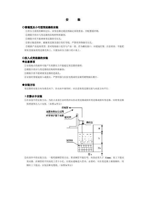
1在静水中安装①在水池中的安装方法:为防止水泵打水时的冲击抖动变送器或损坏变送器或损坏变送器,应将变送器原理液体出入口安装。
(如图a所示)②在深井中的安装方法:一般用插钢管的方法,要求钢管不能打弯,内劲必须大于35mm,易上下提动变动器,在钢管的不同高度上若干小孔,以便水通畅进入管内,必要时,可在变送器上缠烧钢丝,用钢丝上下提动,以免拉断电缆线。
(如图b所示)2在动水中安装在动水中安装时需加静水装置①方法之一:在水道中插入钢管,要求钢管壁稍厚一些,并在其上下不同高度若干个小孔,以阻尼水波和消除动水压力的影响。
(如图c所示)②方法之二:若为清水域的沙石水床,以浅埋为好。
(如图d所示)③方法之三:这种方法即能消除水流压力和波浪的影响又能起到过滤浊水泥沙的作用(如图e所示)○普通型及投入式变送器接线信号(电源)端子设置在电气盒的一个独立腔室内。
接线前,先拧下表盖,把信号(电源)线从穿线孔穿入,把线接在+、-端子及地上,拧紧表盖和穿线孔螺栓。
信号线不要与其它电源线一起穿金属管或放在同一线槽中,也不要再强电设备附近通过。
注意:接好线后,务必将表盖拧紧,以免潮气进入电气盒内,损坏电路。
变送器使用说明书

变送器使⽤说明书⽬录⼀、技术参数 (1)⼆、安装前注意事项 (2)三、安装 (3)四、接线说明 (4)4.1接线端⼦图 (4)4.2仪器接线功能图 (5)4.3接线端⼦说明 (5)4.4电极接线⽰意图 (6)五、按键和界⾯说明 (7)5.1按键说明 (7)5.2界⾯说明 (8)六、操作说明 (11)6.1参数设置操作 (12)6.2校正操作 (13)七、电极保养说明 (16)⼋、操作密码 (17)8.1、参数设置密码 (17)8.2、校正密码 (17)⼀、技术参数⼆、安装前注意事项1、请选择通风良好的位置安装pH计(以下简称仪器),并避免仪器直接受到阳光照射。
2、安装前请阅读本说明书,以免接线不正确导致仪器损坏。
3、在所有接线未完成前,请勿给仪器上电,以免发⽣危险。
4、pH或ORP电极信号传输须采⽤专⽤电极电缆,不能随便⽤⼀般电缆代替,否则将产⽣错误的测量结果。
5、使⽤220VAC的电源时,请避免使⽤三相电源,以免造成电源突波⼲扰。
(若有电源突波⼲扰现象发⽣,可将仪器⽤的电源与动⼒装置电源分开,即仪器采⽤单独电源,或在所有动⼒装置的电源端接突波吸收器来消除突波,如加药机、搅拌机等)。
6、仪器内部的继电器为⼩电流继电器,若要控制较⼤动⼒的附属装置时,请外接电流容量较⼤的继电器,以确保仪器的安全。
7、下图为仪器和动⼒装置的接线⽰意图。
图2-1 仪器和动⼒装置接线⽰意图三、安装1、在配电箱⾯板上开好110+1mm×110+1mm 的仪器安装⽅孔。
2、仪器从配电箱的⾯板直接放⼊,将仪器附带的的固定架卡⼊仪器两侧的固定孔,⽤⼀字型螺丝⼑拧紧固定螺丝。
安装⽰意图如下:主视⽰意图侧视⽰意图(((固定⽰意图开孔尺⼨图3-1 仪器尺⼨和安装⽰意图四、接线说明4.1 接线端⼦图图4-1 仪器接线端⼦图4.2 仪器接线功能图+-RTD图4-2 仪器接线功能图4.4 电极接线⽰意图图4-3电极接线⽰意图五、按键和界⾯说明图5-1 按键⾯板图5.1 按键说明Cal ——校正功能键;Conf ——参数设置功能键;——功能切换/数字循环功能键;——移位功能键;Enter ——确认功能键;5.2 界⾯说明 5.2.1、测量界⾯pH 测量界⾯ ORP 测量界⾯正常⼯作时,若没有进⾏“校正”或“参数设置”操作,仪器显⽰测量界⾯。
美国FOXBORO福克斯波罗变送器
安装方式可选择
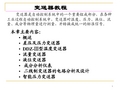
IGP10 结构紧凑, 重量轻, 适于过程直接连接
IGP20 支架安装式适用于较低的测量限值,有多种材料提供
耐用可靠
采用经现场应用考验的多晶硅技术
采用耐腐蚀的环氧树脂涂层
性能优异
精确度达量程的±0.05%
环境温度每变化55℃总的影响为测量范围上限值的±0.05%
公司可提供从简单的需求到最完整的过程控制仪表,阀门,工业过程自动化系统 , 工业调度 SCADA 控制系统和相关服务公司,销售并生产部分福克斯波罗公司的宽量程智能型及常规型仪表,阀门,指示器,记录仪和控制诸如电磁,涡街,质量,浮筒式流量计,压力差压变送器,温度,液位, pH ,电导率和化学组分等过程变量的仪表 。
电磁流量计
I/A系列IM25电磁流量变送器
9300A 系列法兰式电磁流量管
9100A 系列电磁流量管
9200A 系列电磁流量管
8000A 系列园片夹持型电磁流量管
8300A 系列法兰式电磁流量管
E96 系列电磁流量变送器
2800 系列电磁流量管
IGP系列表压力变送器
4~20mA经济型
LCD显示器/按键组态器
对数字/4至20mA型,是备选的;对4至20mA型,是标准的
可对零点,量程.显示单位等进行设定
IDP系列差压变送器
适用性好
316SS 过程外壳和钴-镍-铬传感器作为标准配合
静态压力等级为25MPa
耐用可靠
采用经现场应用考验的多晶硅技术
FOXBORO 产品
84系列旋涡流量计
用于测量液体、气体或蒸汽的流量
测量范围宽
有脉冲,模拟和数字式输出
变送器三按键说明
选择显示模式 (显示压力、电流、百分比)
<M>
<M>
固定电流输出
<S> 选择屏幕显示的电流值 <Z> (3.6,4,8,12,16,20,22.8mA)
确定选择 电流值
<M>
<M>
说明:在参数设置时,若 2 分钟内未有任何按键按下, 则直接返回到测量模式(不保存设置数据)
有源迁移
4mA 点有源迁移
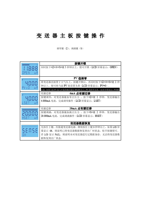
按键调零:对变送器施加零点压力 ,按下<Z>键 2 秒钟,变送器输出
4.000mA 电流,完成调零操作(L按键调满:对变送器施加满点压力 ,按下<S>键 2 秒钟,变送器输出
20.000mA 电流,完成调满操作(LCD 屏幕显示:HSET)
变送器数据恢复
先按住 Z 键,再接通变送器电源,继续按住 Z 键 5 秒钟以上,如果 LCD 屏 幕显示 OK,则说明已将变送器数据恢复到出厂时状态,松开按键便可。 若 LCD 显示 FAIL,则说明未对变送器进行过数据备份,无法将变送器数 据恢复到出厂状态。
以下功能,需三按键同时使用,无需按键开锁。 调零键(Z)、调满键(S)﹑功能键(M)
测量模式设置4ma点量程设置20ma点量程设置阻尼时间设置显示模式固定电流输出mmmmmmz选择修改的数字或小数点选择修改的数字或小数点选择修改的数字或小数点选择显示模式显示压力电流百分比调整数值或小数点位置调整数值或小数点位置调整数值或小数点位置zzssmsssmmmm以下功能需三按键同时使用无需按键开锁
测量模式
<M> <Z>
设置 4mA 点量程
选择修改的数字 <S> 或小数点
变送器使用说明书
目录1技术参数 (2)2安装说明 (3)3接线说明 (5)3.1 变送器(直流供电型)接线端子说明 (6)3.2 变送器(交流供电型)接线端子说明 (7)3.3 仪器接线功能图 (8)3.4 电极接线示意图 (8)4按键和界面说明 (9)4.1 按键及指示灯说明 (9)4.2 界面说明 (10)5操作说明 (13)5.1 参数设置操作 (14)5.2 校正操作 (15)6电极诊断及出错信息 (17)7电极保养说明 (19)8操作密码 (20)8.1 参数设置密码 (20)8.2 校正密码 (20)附1缓冲液 (21)附2技术术语 (23)安全预防措施请认真阅读并遵守下列要求!在仪器上电前,请对照您持有仪表的型号,确认供电电压:变送器需用18V-30VDC直流电源供电变送器需用100V-250V AC交流电源供电打开仪器会有电路部分暴露,因此除了接线仓和仪表透明罩外,不应打开仪器其它部分。
打开的仪器内部能接触到的器件上的电压足以威胁人的生命。
若需检修,需要返回厂家。
只有厂家专业人员才能在带电情况下打开仪器。
当相应的保护失效时,请停止操作。
出现以下情况时,保护可能失效:◇仪器外观有明显破损◇仪器不能正常测量◇长期储存于超过70℃的环境中◇经过剧烈的震动或碰撞后11 技术参数22安装说明①31、请选择合适位置安装pH计(以下简称仪器),避免仪器直接受到阳光照射。
2、安装前请阅读本说明书,以免接线不正确导致仪器损坏。
3、pH或ORP电极信号传输须采用专用电极电缆,请不要用一般电缆代替,否则将产生错误的测量结果。
4、仪器内部的继电器为小电流继电器,若要控制较大动力的图2-1 仪器和动力装置接线示意图43 接线说明接线仓内部图(拆掉压线盖)接线步骤:打开接线仓盖→拆下压线盖→接线→装上压线盖→装上接线仓盖。
5673.3 仪器接线功能图84 按键和界面说明Wash 灯:清洗指示灯,当清洗继电器动作时,此灯亮Alarm灯:报警指示灯,仪表超限报警或自检报警时,此灯亮94.2 界面说明4.2.1 测量界面入码自动清零,请操作人员重新输入。
变送器说明书样本

第一章概述重量变送器适用于有模拟输出接口要求的衡器, 也适用对控制精度、速度要求不高的定量输出功能的衡器。
1.1 特点本仪表主要特点如下:☆数字校准: 能够有两点非线性校准。
☆丰富的接口功能: RS-232C一个、 0/4~20mA模拟输出接口一个、定值输出点2个。
第二章安装2.1 安装要求: 应符合第一章中1.2.2 工作环境的要求。
2.1.1 请不要将本仪表安装在如下条件环境中:1) 阳光直射处2) 靠近热源、水源处3) 暴露在雨环境下4) 温差变化较大5) 粉尘严重或存在易燃、易爆、腐蚀性气体2.1.2 最好的工作条件为室温20℃, 湿度为50%RH。
2.1.3 本仪表电源接地应确保良好( 小于4欧姆) 且不得与其它用电设备共地。
2.1.4请不要将传感器信号线与电力电缆一同铺设。
2.1.5供电电源应稳定, 否则需加装电源净化设备。
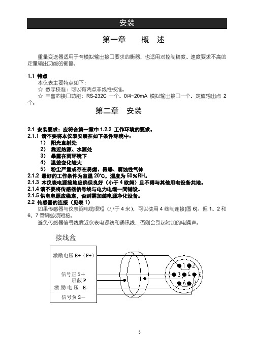
2.2 传感器的连接( 见表1)如果传感器与仪表间电缆很短( 小于4米) , 能够使用4线制连接(图6)。
但1、 2和6、 7管脚必须短接。
避免传感器信号线靠近仪表电源线和通讯线, 否则会引起附加的电噪声。
图1 四线制连接激励电压激励电压 信号负S屏蔽信号正S接线盒接线盒激励电压信号正S屏蔽激励电压信号负S图2 六线制连接表1 传感器连接表管脚 1 2 3 4 5 6 7定义激励电压正反馈电压正信号正屏蔽信号负反馈电压负激励电压负符号E+F+S+P S-F-E-第三章基本操作3.1正常工作1.仪表可根据传感器的输出信号的输出相应的电流值2.该仪表能够设定两个定量值, 且可根据设定的两个定量值输出定量点控制信号。
当仪表输出值大于”HH”设定值时, 则”HH”定量点开关量输出。
当仪表输出值小于”LL”设定值时, 则”LL”定量点开关量输出。
3.2 定值输出功能在称重状态下, 按〖设定〗键, 仪表进入用户编程状态, 将”CoP-En”设为1X, 仪表前面板上的”定值”标志指示, 则仪表可根据”-HH-”、”-LL-”2个定值点的设定数值大小输出定值点信号。
压力变送器详细操作指南

目录1. 按键功能概述 (1)1.1. 按键模式说明 (1)2. 按键功能 (1)2.1. 输入操作码 (1)2.1.1. 操作码及对应功能 (1)2.1.2. 操作码输入方法 (2)2.2. 设置单位 (3)2.3. 设置量程下限 (3)2.4. 设置量程上限 (5)2.5. 设置阻尼 (5)2.6. 主变量调零(清零)功能 (5)2.7. 设置输出特性 (6)2.8. 校准下限 (7)2.9. 校准上限 (7)2.10. 零点迁移与量程迁移[调零和调满] (8)2.11. 显示变量设置 (8)3. 恢复出厂设置 (9)按键详细操作指南1.按键功能概述1.1. 按键模式说明标准的H3051S和H3051T表头上都有三个按键,分别为“M”、“S”、“Z”。
也支持外部扩展干簧管接口,实现不开盖调整。
此时支持两个按键,分别为“S”、“Z”。
针对这两种应用,本产品支持“双按键”和“三按键”两种操作模式。
“三按键”操作模式:操作更快捷,适用于LCD上具备3个按键的产品。
➢Z键用于进入提示数据设置界面和移位;➢S键用于进入数据设置界面、增加数字和数据保存;➢M键用于数据保存。
注:在三按键模式下,任何时候都可以按下“M“键,保存当前的设置数据。
“双按键”操作模式:这种操作模式通常用于外部只有2个非接触按键的情况。
➢Z键用于进入提示数据设置界面和移位;➢S键用于进入数据设置界面、增加数字和数据保存。
注:在双按键模式下,输入数据时,必须等左下角的下箭头闪烁时,才能通过按下“Z”键保存设置数据。
2.按键功能2.1. 输入操作码2.1.1.操作码及对应功能现场使用按键组态时,LCD左下角“88”字符用于表示当前设置变量类型,也就是当前按键所执左下角“88”字符显示设置变量0或空正常显示1 输入操作码(可以直接输入和下面功能对应的数字,以直接进行相应功能的设置)2 设置单位3 设置量程下限4 设置量程上限5 设置阻尼6 主变量调零7 零点迁移与量程迁移[调零和调满]8 输出特性【设置线性输出、或者开方输出】9 校准下限10 校准上限➢例如输入“5”,直接进入设置阻尼功能。
变送器说明书
2.2传感器的连接(见表1)
如果传感器与仪表间电缆很短(小于4米),可以使用4线制连接(图6)。但1、2和6、7管脚必须短接。
避免传感器信号线靠近仪表电源线和通讯线,否则会引起附加的电噪声。
图1四线制连接
图2六线制连接
表1传感器连接表
管脚
1
2
3
4
5
6
f.显示变为:“CAL0”
(ⅰ)若不进行空秤校准,可按下〖设定〗键直接进入第g步.
(ⅱ)若进行空秤校准,则保持衡器为空秤,待“静止”标志指示后,按下〖确认〗键。
c.选择后,按下〖确认〗键,显示变为:“d XX”,进入分度值设定,其中“XX”表示分度值,分为:“1、2、5、10、20、50”共6种,可通过〖〗、〖〗键来选择。
d.选择后,按下〖确认〗键,显示变为:“XXXXXX”,提示进行量程选择,可通过〖〗、〖〗选择。见表4-1。
e.选择后,按下〖确认〗键,则仪表进入零点校准。
7
定义
激励电压正
反馈电压正
信号正
屏蔽
信号负
反馈电压负
激励电压负
符号
E+
F+
S+
P
S-
F-
E-
第三章基本操作
3.1正常工作
1.仪表可根据传感器的输出信号的输出相应的电流值
2.该仪表可以设定两个定量值,且可根据设定的两个定量值输出定量点控制信号。当仪表输出值大于“HH”设定值时,则“HH”定量点开关量输出。当仪表输出值小于“LL”设定值时,则“LL”定量点开关量输出。
1时:大于等于“-LL-”设定值、大于等于“HH”设定值有定量点开关量输出。
2时:小于等于“-LL-”设定值、小于等于“HH”设定值有定量点开关量输出。
foxboro维护手册

I/A’s系统维护手册(工程师手册)编制:何卫兵上海•福克斯波罗有限公司二零零二年元月第一章系统概述本手册为上海福克斯波罗有限公司DCS系统I/A维护手册,并作为I/A’s 培训手册的补充。
用户可以结合两本手册来进行系统操作、软件组态及系统维护。
必要时还应参考随机的原版资料及福克斯波罗公司提供的中文培训手册。
本手册针对福克斯波罗制造的I/A’S,采用Solaris 2.5.1操作系统和I/A’s 6.2.1版本应用软件。
整个系统为一个节点,在冗余的节点总线DNBI上挂有:●三台工程师站AW5101、AW5102、AW5103该站作为工程师站,内置256M内存及8GB硬盘,AW5102外挂一台喷墨打印机(电缆长度15米),AW5103配有和MIS系统通讯用的第二以太网卡。
该工作站安放在工程师站内,与I/A机柜(位于电子间)之间的通讯电缆长度为30米。
●四台操作员站WP5101、WP5103、WP5104、WP5105该站内置128M内存及8GB硬盘,并各配有一个21”的CRT。
该工作站安放在主控室内与I/A机柜(位于电子间)之间的通讯电缆长度为30米。
●一台操作员站WP5102该站作为大屏幕操作站,内置128M内存及8GB硬盘,除配有一个21”的CRT外。
还配有一台用于显示大屏幕的以太网卡。
该工作站安放在主控室内,与I/A机柜(位于电子间)之间的通讯电缆长度为30米。
十一对容错台控制处理站CP4001、CP4002、CP4003、CP4004、CP4005、CP4006、CP4007、CP4008、CP4009、CP4010、CP4011此容错型控制处理站CP40BFT,用于实现DCS系统的数据采集及控制。
该控制处理器安放在电子间内。
现场由十八个装有现场总线组件FBM的现场机柜、十个安装DCS系统辅助装置(包括冗余的24VDC电源、交流继电器、直流继电器、SIMENSE交流接触器、以及相应的I/O端子)的继电器柜、一个DCS系统220VAC配电柜共同构成。
差压变送器正确操作使用步骤 变送器如何操作

差压变送器正确操作使用步骤变送器如何操作对于工业上大部门的差压变送器,不管是HART协议和布朗协议等差压变送器,安装与调校应注意以下几个问题:1、正确进行误差及回差的计算,正确给出校验结论,正确给出校验结论,正确进行有效数字的处理。
2、设备复位整理:停用三阀组,停电、拆除回路连线及相关设备,压力掌控台启动关闭,打开截止阀及回检阀。
3、校验仪设置功能项,校验仪首先清零,压力管路连接好,同时注意正负极连接,接入标准电阻。
检查回路电流。
4、变送器精度校验:将微调阀放到中心位置,关闭截止阀及回检阀,电动压力检验台输出压力设置,基本误差调校(上行5点,下行5点),适时记录数据。
5、安装时候常常显现松动,变送器与三阀组链接,螺栓应对角缩紧,一般不能一次锁死,三阀组安装时候应当加密封线圈。
6、正确的挂接手操器,依照要求设置变送器内容,零位调整。
7、对于三阀组的操作:首先打开平衡阀,正确开高压阀。
差压变送器在测量过程中常会显现一些故障,因此,在确定程度上影响生产的正常进行,依据相关人员现场多年的实践阅历,总结了一些常见故障判定分析和解决方法。
线路故障:当计算机显示数值不正常时,首先要打开智能差压变送器的接线盒,检查线路是否虚接、短接或者断接,可以通过测电源、量电阻、摇绝缘等方法,进行故障的判定和处理。
采集模块或差压传感器故障:当线路故障排出时,就要看是不是采集模块或差压传感器故障。
使用万用表检查智能差压变送器工作电源是否正常,同时测量智能差压变送器的输出电流值是否在4mA~20mA(假如为输出电压值,测量是否在0~5V)范围内,确认输出值是否正常。
假如无输出值,智能差压变送器损坏,需要更换差压变送器。
假如现场测量值换算与实际阅历值相符,则现场仪表和测点无问题,模块损坏,需更换模块。
当现场测量值换算与计算机显示值相同,说明引压管或智能差压变送器有问题。
引压管故障:1.引压管漏气—由于差压变送器接点、截止阀等附件比较多,导致泄漏点增多,维护工作量增大。
CCS系统操作员使用手册
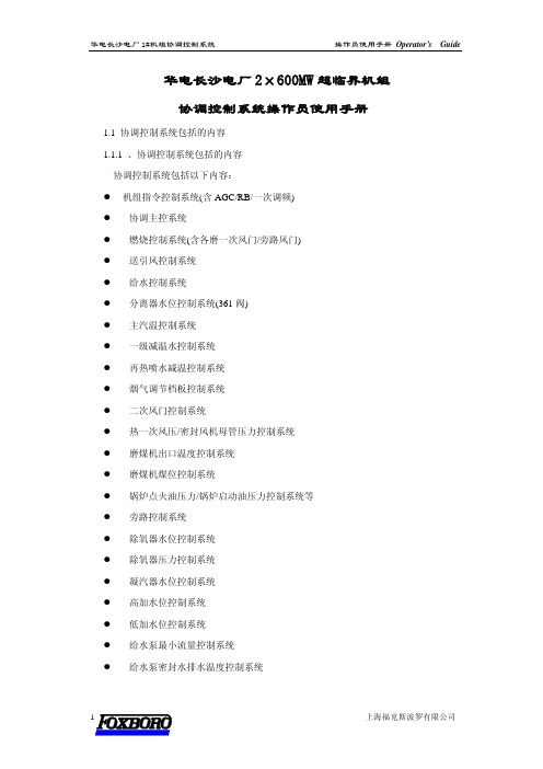
华电长沙电厂2×600MW超临界机组协调控制系统操作员使用手册1.1 协调控制系统包括的内容1.1.1 、协调控制系统包括的内容协调控制系统包括以下内容:z机组指令控制系统(含AGC/RB/一次调频)z协调主控系统z燃烧控制系统(含各磨一次风门/旁路风门)z送引风控制系统z给水控制系统z分离器水位控制系统(361阀)z主汽温控制系统z一级减温水控制系统z再热喷水减温控制系统z烟气调节档板控制系统z二次风门控制系统z热一次风压/密封风机母管压力控制系统z磨煤机出口温度控制系统z磨煤机煤位控制系统z锅炉点火油压力/锅炉启动油压力控制系统等z旁路控制系统z除氧器水位控制系统z除氧器压力控制系统z凝汽器水位控制系统z高加水位控制系统z低加水位控制系统z给水泵最小流量控制系统z给水泵密封水排水温度控制系统z轴封控制系统z辅汽控制系统z低压缸喷水减温控制系统z凝结水补水控制系统z发电机侧单回路控制系统等1.2协调控制系统的操作说明1.2.1协调控制系统的设备说明华电长沙协调控制系统具有两种操作方式:手动和自动。
手动时,操作员在LCD 流程显示画面上或MCS操作画面上手动操作阀位指令,直接控制被控对象;自动时,操作员在LCD流程显示画面上或MCS操作画面上手动设定被控参数的目标值,间接控制被控对象。
流程显示画面上弹出的软手操器的介绍:如图1-1所示为软手操操作器,操作器的各部分已经标明。
操作器的手/自动按钮完成控制系统的手自动切换,自动按钮在自动控制方式下是绿色,手动方式下是灰色。
手动按钮在自动方式下是灰色,手动方式下是绿色,系统强制切手动方式下是红色,此时投不上自动。
操作器上的信息框反映了控制系统不能投自动的原因,当有故障因素影响控制系统不能投自动,信息框显示红底。
信息有以下几种:信息框字符含义表TRANSF 变送器故障TRIP 跳闸transf 1个变送器故障(不切手动) MFT 主燃料跳闸GASP 喘振(风机才有)NDE/DE 非驱动端/驱动端HIDEV,HDAIND 高偏差报警SWEEP 吹扫LODEV,LDAIND 低偏差报警IDF MAN 引风手动VLVDEV 阀位偏差报警FUEL MAN 燃料手动OPEN 强制开BL MAN 锅炉主控手动(燃料手动)CLOSE 强制关TI MAN 汽机主控手动(DEH控制器手动)设定值设定及显示:该框可以进行给定值设定,当鼠标指向该框会出现一个方框,按下鼠标左键,会出现一个黄框表示可以对该框的内容进行设定。
变送器教程资料
31
下图是采用4段折线逼近热电偶的特性原理图
折线逼近法线性化原理 a)折线逼近原理 b)电路原理图
32
1)当Vf电压使运放输出Vc<Vf1时,对应变送器的零点,即 I0=4mA或V0=1V; 2) 当Vf增加,Vf1<Vc≤Vf2时,VS1~VS3均截止,电阻网络取 决于Rf17、Rf18、Rf7和Rf8,此时折线斜率为α1;
图2-2 变送器的零点调整与零点迁移 a)零点调整 b)正零点迁移 c)负零点迁移
7
实例 某测温仪表的量程为0~500℃,
输出信号为4~20mA ,
现欲测量200~1000℃应如何调整?
8
2. 变送器的信号: 将各种物理量转换成统一的标准信号,标准信号是 仪表(不同厂家的仪表)之间的协议。
由0~10mA(0~5V,0~10V) →4~20mA(1~5V) →全数字化双向通信信号。 DDZ-Ⅱ DDZ-Ⅲ
12
电容式差压变送器组成方框图
13
1. 敏感器结构(测量部分)
差动电容式敏感器如下图所示。其核心是由中心可 动极板与两侧固定极板构成的。差动球-平面型电容CL 和CH。
14
结构特点:可承受过压能力强,适合于测量 绝对压力很高,而压差很小的场合。即使一侧的 压力消失,使膜片贴在壳体上,不再继续变形, 而不致破裂。 当两侧压力相等,P1=P2时,中心膜片无位移 =0,CL=CH≈150pf。 当两侧压力不相等,P1≠P2时,⊿P=P2-P1,中 心膜片的位移 δ=k⊿P,
从使用的角度来说,变送器量程调整、零点调整和零点 迁移的概念是很重要的。
量程调整或称满度调整,其目 的是使变送器输出信号的上限值 (或满度值)ymax与输入测量信号 上限值 xmax 相对应。量程调整相 当于改变变送器的灵敏度,即输 入输出特性的斜率,见图2-1。
压力变送器详细操作指南教学教材
压⼒变送器详细操作指南教学教材压⼒变送器详细操作指南⽬录1.按键功能概述 (1)1.1.按键模式说明 (1)2.按键功能 (1)2.1.输⼊操作码 (1)2.1.1.操作码及对应功能 (1)2.1.2.操作码输⼊⽅法 (2)2.2.设置单位 (3)2.3.设置量程下限 (4)2.4.设置量程上限 (5)2.5.设置阻尼 (5)2.6.主变量调零(清零)功能 (6)2.7.设置输出特性 (6)2.8.校准下限 (7)2.9.校准上限 (7)2.10................................................................................................. 零点迁移与量程迁移 [调零和调满] 82.11.显⽰变量设置 (9)3.恢复出⼚设置 (9)按键详细操作指南1.按键功能概述1.1. 按键模式说明标准的H3051S和H3051T表头上都有三个按键,分别为“M”、“S”、“Z”。
也⽀持外部扩展⼲簧管接⼝,实现不开盖调整。
此时⽀持两个按键,分别为“S”、“Z”。
针对这两种应⽤,本产品⽀持“双按键”和“三按键”两种操作模式。
“三按键”操作模式:操作更快捷,适⽤于LCD上具备3个按键的产品。
Z键⽤于进⼊提⽰数据设置界⾯和移位;S键⽤于进⼊数据设置界⾯、增加数字和数据保存;M键⽤于数据保存。
注:在三按键模式下,任何时候都可以按下“M“键,保存当前的设置数据。
“双按键”操作模式:这种操作模式通常⽤于外部只有2个⾮接触按键的情况。
Z键⽤于进⼊提⽰数据设置界⾯和移位;S键⽤于进⼊数据设置界⾯、增加数字和数据保存。
注:在双按键模式下,输⼊数据时,必须等左下⾓的下箭头闪烁时,才能通过按下“Z”键保存设置数据。
2.按键功能2.1. 输⼊操作码2.1.1.操作码及对应功能现场使⽤按键组态时,LCD左下⾓“88”字符⽤于表⽰当前设置变量类型,也就是当前按键所执⾏的设置功能。
福克斯波罗
第三章控制组态在我们把 I/A‟s系统软硬件到位安装好以后,要做的工作就是把控制方案组态到机器里,这样就可以开车了。
I/A‟s 提供了一些缺省的显示操作方法。
由于 I/A‟s的开放性,我们不一定要等设备到货后才做这项工作,只要有一台装入了 PW-C 软件的个人计算机就可以把所有的组态工作做好。
在这一章我们主要学习如何使用 CIO 组态器,以及 Compound、Block 的基本概念和一些重要的模块参数,如需深入了解看请随机资料。
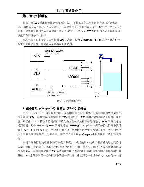
1. 组合模块(Compound)和模块(Block)的概念图3-1 构筑了一个液位控制回路,现场测量信号通过FBM 的第四通道接到模拟信号输入模块AIN,将其转换成数字量交PID 模块处理,PID 模块按控制要求计算阀门的开度,最后由AOUT 模块将控制阀门开度的数字量转换成模拟信号再通过FBM 的第八通道送到现场。
其中 AIO001 是 FBM 的通讯地址 (letterbug)。
在这样一个简单的控制回路中就用到了AIN、PID 和AOUT 三个模块,而且这三个模块在回路中有密切的关系,我们通常把相互有联系的模块放在一个集合中,并把这个集合称为Compound 组合模块(或功能块组合)。
控制回路由控制处理机中的组合模块和模块(或功能块)构成。
组合模块是实现控制方案的模块的逻辑集合。
模块是为实现某个控制任务的一组算法。
图3-2 表示组合模块与模块的关系。
组合模块提供了 I/A 系统集成控制(连续控制、梯形逻辑控制、顺序控制)的基础。
I/A 系统中的任一组合模块中的任一模块可以连接到另一个组合模块中的任何一个模3-1块。
模块含有决定模块性能的参数,参数值的类型有实型(Real)、布尔型(Boolean)、整形(Integer)和字符串型(String)。
图 3-2 Compound 和 Block 的关系(虚线内表示 CP)2.组合模块(Compound)和模块(Block)的功能组合模块(又称功能块组合)对它属下的模块提供下列功能:按照报警优先级对过程报警进行屏蔽,对报警设备进行分组,指示当前报警的最高级别。
- 1、下载文档前请自行甄别文档内容的完整性,平台不提供额外的编辑、内容补充、找答案等附加服务。
- 2、"仅部分预览"的文档,不可在线预览部分如存在完整性等问题,可反馈申请退款(可完整预览的文档不适用该条件!)。
- 3、如文档侵犯您的权益,请联系客服反馈,我们会尽快为您处理(人工客服工作时间:9:00-18:30)。
MI 020-359August 2010InstructionUniversal Instruction ManualI/A Series ® Pressure TransmittersModels IAP10, IAP20,IGP10, IGP20, IGP25 and IGP50,IDP10, IDP25, IDP50Configuration, Calibration, Installation, and OperationSafety information in many languages is available on our website. For help downloading this information, contact our Global Customer Support Center.MI 020-359 – August 2010ContentsFigures (vii)Tables (ix)Preface (xi)1. Safety Information (1)Transmitter Identification (1)Supply Voltage (1)Electrical Certification Rating (2)PED Certification (2)Pressure Rating (2)Pressure Seal PSFLT (3)Pressure Seals PSFPS and PSFES (4)Pressure Seals PSFAR and PSFAD (5)Pressure Seals PSTAR and PSTAD (5)Pressure Seals PSISR and PSISD (6)Pressure Seals PSSCR and PSSCT (6)PSSSR and PSSST (Sanitary Tank Spud) Seals (6)Origin Code (6)Operating Temperature Limits (6)Process Wetted Materials (10)Pressure Seals PSFLT, PSFPS, and PSFES (10)Pressure Seals PSFAR, PSFAD, PSTAR, PSTAD, PSISR, and PSISD (10)Pressure Seals PSSCR (12)Pressure Seals PSSCT (12)Pressure Seals PSSSR and PSSST (12)Warnings (12)General Warning (12)ATEX Warnings (13)Explosionproof/Flameproof and Enclosure Warning (13)Intrinsically Safe and Type n Warning (14)Type n Warning (14)Pressure Warnings (14)Process Fluid Warning (16)Seal or Sensor Fill Fluid Warning (16)Parts Replacement Warning (16)EC Declaration of Conformity (17)2. Installation (19)Mechanical Installation (19)Differential Pressure Transmitter (19)Process-Mounted Transmitter (20)Manifold Mounted Transmitter (20)iiiMI 020-359 – August 2010 ContentsivPipe- or Surface-Mounted Transmitter (22)Venting and Draining (27)Installation of Flow Measurement Piping (28)Filling System with Seal Liquid (30)Absolute and Gauge Pressure Transmitter (31)IAP10, IGP10, IGP25 and IGP50 Transmitters (31)IAP20 and IGP20 Transmitters (32)Typical Transmitter Piping (33)Transmitter with Seals (34)Positioning the Housing (35)Positioning the Display (35)Setting the Write Protect Jumper (35)Cover Locks (36)Wiring (36)4 to 20 mA Output Signal (Model Codes -A, -D, and -T) (37)HART Multidrop Wiring (Model Code -T) (41)1 to 5 V dc Output Signal (Model Code -V) (42)Power Supply Voltage and Current (42)Output Load (42)Three or Four Wire Connections (42)FoxCom Communications Protocol (Model Code -D) (45)Foundation Fieldbus Communication (Model Code -F) (47)Installing Fieldbus Software (Model Code -F) (49)Putting a Differential Pressure Xmtr Into Operation (50)Taking a Differential Pressure Xmtr Out of Operation (50)3. Operation Using Local Display (51)Moving Through the Menu Structure (53)Entering Numerical Values (53)Zeroing from the LCD Indicator Pushbuttons or Optional External Zero Button (54)Zeroing from a HART Communicator (55)4. Calibration (57)Calibration Diagram (57)Liquid Level Application Calibrated Range Values (58)Method #1 - Calculating the range values (61)Method #2 - Using the Transmitters to Determine the Range Values (61)Method #3 - Getting the Local Indicator and Transmitted Value to Indicate Level - HART Transmitters (62)Method #4 - Getting the Local Indicator and Transmitted Value to Indicate Level - Analog Output Transmitters (63)5. Configuration Diagrams (65)FoxCom Communications (Code -D) (65)HART Communications (Code -T) (68)Contents MI 020-359– August 2010Foundation Fieldbus Communications (Code -F) (71)4 to 20 mA (Code -A) and 1 to 5 V dc (Code -V) (72)Index (73)vMI 020-359 – August 2010 Contents viFigures1 Sample Transmitter Identification (1)2 Sample Seal Data Plate (2)3 Pressure Connections (14)4 Sensor Replacement (15)5 Sensor Replacement (pvdf Inserts) (15)6 Typical Mounting of an IDP Transmitter Supported by Process Piping (20)7 Typical Mounting of an IDP Transmitter Supported by a Bypass Manifold (20)8 Typical Mounting of M4A and M4T Manifold with -AM Bracket (21)9 Typical Mounting of MB3 Manifold with -AM Bracket (21)10 Typical Mounting of IMV25 Transmitter on Coplanar‰ Manifold (22)11 Pipe or Surface Mounted Transmitter Using a Standard Bracket (23)12 Examples of Mounting With a Standard Bracket (23)13 Details of a Universal Bracket (24)14 Mounting a Transmitter with Traditional Structure Using a Universal Bracket (25)15 Vertical Pipe Mounting a Transmitter with LP2 Structure Using a Universal Bracket ..2516 Horizontal Mounting a Transmitter with LP2 Structure Using a Universal Bracket (26)17 Vertical Mounting - Cavity Draining (27)18 Vertical Mounting - Cavity Venting (27)19 Horizontal Mounting - Cavity Venting (27)20 Vertical Mounting - Cavity Venting (28)21 Horizontal Mounting - Cavity Venting and Draining (28)22 Cavity Venting and Draining (28)23 Example of Horizontal Process Line Installation (29)24 Example of Vertical Process Line Installation (30)25 IAP10, IGP10, IGP25, and IGP50 Transmitter Mounting (31)26 IAP20 and IGP20 Transmitter Mounting (32)27 Typical Transmitter Piping (IGP10 shown) (33)28 Hot Process Piping (34)29 Housing Screw or Clip Location (35)30 Accessing Field Terminals (36)31 Identification of Field Terminals (37)32 Supply Voltage and Loop Load (38)33 Loop Wiring 4 to 20 mA Output Transmitters (40)34 Wiring Several 4 to 20 mA Transmitters to a Common Power Supply (40)35 Typical Multidrop Network (41)36 Identification of Field Terminals (42)37 Three-wire Connection (43)38 Four-wire Connection (43)39 Loop Wiring (four-wire connection shown) (44)40 Wiring Several Transmitters to a Common Power Supply (45)41 Typical Transmitter Wiring to an I/A Series System (46)42 Wiring Diagram of Typical FOUNDATION Fieldbus Transmitter Installation (48)43 Local Display Module (52)viiMI 020-359 – August 2010 Figures44 Top Level Structure Diagram (52)45 Typical Menu Structure (53)46 Calibration Structure Diagram (57)47 Calibration Structure Diagram (Continued) (58)48 Transmitter Connected to Open Tank (59)49 Transmitter Connected to Closed Tank with Dry Leg (59)50 Transmitter Connected to Closed Tank with Wet Leg (60)51 Transmitter Connected to Closed Tank With Dual Seals (60)52 FoxCom Configuration Structure Diagram (65)53 FoxCom Configuration Structure Diagram (Continued) (66)54 FoxCom Configuration Structure Diagram (Continued) (67)55 Configuration Structure Diagram (68)56 Configuration Structure Diagram (Continued) (69)57 Configuration Structure Diagram (Continued) (70)58 Configuration Structure Diagram (Code -A and -V) (72)viiiTables1 Pressure Seal PSFLT Pressure Limits (3)2 Pressure Seal PSFPS and PSFES Pressure Limits (4)3 Pressure Seals PSFAR and PSFAD Pressure Limits (5)4 Pressure Seals PSTAR and PSTAD Pressure Limits (5)5 Interpretation of Model Code forIDP10, IAP20, IGP20, IDP25, and IDP50 Transmitters (6)6 Interpretation of Model Code forIAP10, IGP10, IGP25, and IGP50 Transmitters (8)7 Sensor Body Operating Temperature Limits for Models Listed in Tables 5 and 6 (9)8 Seal Fill Fluid and Operating Temperature Limits (10)9 Pressure Seal PSFLT, PSFPS, and PSFES Wetted Materials (10)10 Pressure Seal Lower Housing Materials (10)11 Pressure Seal Diaphragm Materials (11)12 Pressure Seal Gasket Materials (11)13 Pressure Seal PSSCR Diaphragm Materials (12)14 Capillary Fill Fluid Specific Gravities (34)15 Minimum Supply Voltage Requirements (47)ixMI 020-359 – August 2010 Tables xPrefaceThis Universal Instruction Manual is designed to provide the user with a single, concise, easy-to-use manual that covers the key points needed for configuration, calibration, installation, and operation of I/A Series Pressure T ransmitters.It covers all models of single variable pressure transmitters in the I/A Series family, including absolute, gauge, and differential pressure transmitters, with FoxCom, HART, F OUNDATION fieldbus, or analog output electronics.This universal manual, along with a CD containing detailed information, is provided free of charge with every I/A Series Pressure T ransmitter, unless the purchaser requests that these two items be omitted.For additional detailed information about each model, including dimensional prints, parts lists, and more detailed instructions, please refer to the standard CD supplied or the optional paper instruction book that is available from Invensys for each model in the line.♦Standard Documentation Shipped with every I/A Series Pressure T ransmitter ♦ A brief “Getting Started” Pocket-Sized Bulletin♦This Universal Instruction Manual♦ A CD that contains the complete documentation set for I/A Series Pressure T ransmitters♦When Optional Feature K1 is specified in the Model Code when the transmitter is ordered:A brief “Getting Started” Pocket-Sized Bulletin only is suppliedOptional Feature K1 is offered for those users who want Invensys to omit thedocumentation shipped with every transmitter. This may be specified when multipleidentical transmitters are ordered and the user does not want multiple sets ofdocumentation.xiMI 020-359 – August 2010 Preface xii11. Safety InformationTransmitter IdentificationA typical data plate is shown in Figure 1.Figure 1. Sample Transmitter IdentificationReview the model code on the data plate attached to your transmitter to determine its electrical, pressure, and hazardous location ratings.Supply VoltageThe proper supply voltage is printed on the data plate. See Item C on the example shown in Figure1. Ensure that the proper electrical source is connected to the transmitter.CFD IDP10-D 12 A 21E - A 32A01253625 psiE AB 11.5 - 42 V dcSILICONE FILL -46 AND 121 CMI 020-359 – August 2010 1. Safety Information2Electrical Certification RatingThe electrical safety design code is printed on the data plate as part of the model code. See Item B on the example shown in Figure1. See the "Product Safety Specifications" section of the instruction pertaining to your instrument on the enclosed CD-ROM to identify this code. The type of protection is also marked on the data plate. See Item D on the example shown in Figure1. PED CertificationInvensys offers the PED (Harmonized Pressure Equipment Directive for the European Community) certification only with transmitters ordered with ATEX Electrical Safety Design Code selections. T ransmitters with PED certification have a CE marking on the data plate that also carries the PED number 0575.Pressure RatingThe maximum working pressure (PS or MWP) for the transmitter is printed on the data plate. See Item F on the example shown in Figure1.The data plate of flanged level transmitters and transmitters with flanged pressure seals are stamped with the MWP if the transmitter pressure range is the limiting factor. It is stamped “Flange Rate” if the flange rating is the limiting factor. The MWP of the flanged seal is stamped on the seal data plate. See Figure2.Figure 2. Sample Seal Data PlateWhen using transmitters with threaded, in-line saddle weld, or sanitary pressure seals, compare the MWP of the transmitter on the transmitter data plate and the MWP of the seals on the seals data plates and use the lesser value as the system MWP.The MWP on the seal data plates may not be given at your process temperature. Use the following information and industry standards as required to determine the actual pressure limits for your application.MODEL CODE: PSFPS-A2S0E313B MWP: 275 psig at 100°FNOTICE: BREAKING CONNECTIONS VOIDS WARRANTYBE SURE FILL FLUID CAN MIX SAFEL Y WITH PROCESS HIGH SIDE SEALHIGH SIDE FLUID, DC200, 10 cSt SILICONE TEMP RANGE -40 TO +450°FPROCESS WETTED MA TERIAL 316 SS1. Safety Information MI 020-359– August 20103Pressure Seal PSFLTT able 1. Pressure Seal PSFLT Pressure LimitsProcessConnections Flange Process T emperature (c)Maximum Working Pressure Carbon Steel (d)316L Stainless Steel (e)ANSI Class 150 (a)100°F 200°F 300°F 450°F 285 psig 260 psig 230 psig 185 psig 275 psig 240 psig 215 psig 183 psig ANSI Class 300 (a)100°F 200°F 300°F 450°F 740 psig 675 psig 655 psig 618 psig 720 psig 620 psig 560 psig 498 psig ANSI Class 600 (a)100°F 200°F 300°F 450°F 1480 psig 1350 psig 1315 psig 1235 psig 1440 psig 1240 psig 1120 psig 993 psig DIN PN 10/16 (b)50°C 100°C 150°C 250°C 16 bar 16 bar 14.5 bar 11 bar 16 bar 16 bar 14 bar 10.5 bar DIN PN 10/40and PN 25/40 (b)50°C 100°C 150°C 250°C40 bar 40 bar 37.5 bar 32 bar40 bar 35 bar 33.5 bar 30 bar(a)ANSI flanges per ASME/ANSI B16.5-1988 (b)DIN flanges per BS4504.(c)Flange temperature/pressure ratings only; seal temperature ratings may be lower; refer to Table 8. (d)ASME/ANSI Material Group 1.1; linear interpolation acceptable. (e)ASME/ANSI Material Group 2.2; linear interpolation acceptable.MI 020-359 – August 2010 1. Safety Information4Pressure Seals PSFPS and PSFEST able 2. Pressure Seal PSFPS and PSFES Pressure LimitsProcess ConnectionFlangeProcessT emperature(c)Maximum Working PressureCarbon Steel (d)316L Stainless Steel (e) ANSI Class 150 (a)100°F200°F400°F500°F600°F285 psig230 psig200 psig170 psig140 psig275 psig240 psig195 psig170 psig140 psig ANSI Class 300 (a)100°F200°F400°F500°F600°F740 psig675 psig635 psig600 psig550 psig720 psig620 psig515 psig480 psig450 psig ANSI Class 600 (a)100°F200°F400°F500°F600°F1480 psig1350 psig1270 psig1200 psig1095 psig1440 psig1240 psig1030 psig955 psig905 psigDIN PN 10/16 (b) 50°C100°C150°C200°C300°C16 bar16 bar14.5 bar13 bar9 bar16 bar16 bar14 bar12 bar9 barDIN PN 10/40and PN 25/40 (b)50°C100°C150°C200°C300°C40 bar40 bar37.5 bar35 bar28 bar40 bar35 bar33.5 bar32 bar28 bar(a)ANSI flanges per ASME/ANSI B16.5-1988(b)DIN flanges per BS4504.(c)Flange temperature/pressure ratings only; seal temperature ratings may be lower; refer to Table8.(d)ASME/ANSI Material Group 1.1; linear interpolation acceptable.(e)ASME/ANSI Material Group 2.2; linear interpolation acceptable.1. Safety Information MI 020-359– August 20105Pressure Seals PSFAR and PSFADPressure Seals PSTAR and PSTADThe pressure rating is dependent on the diaphragm size and the bolting material. The diaphragm size and bolting material are identified in the pressure seal model number which is located on the pressure seal. See following example:T able 3. Pressure Seals PSFAR and PSFAD Pressure LimitsProcess Connection Flange Process T emperature (b)Pressure Rating in psig (a)Class 150Class 300Class 600Class 1500ANSICarbon Steel-20°F 100°F 200°F300°F400°F 500°F 580°F 28528526023020017014674074067565563560056014801480135013151270120011203705370533753280317029952785ANSIStainless Steel-20°F 100°F 200°F300°F400°F 500°F 580°F275275240215195170146720720620560515480456144014401240112010309559153600360030952795257023902280(a) The maximum working pressure with the nonmetallic ptfe and PVC lower housings is 150 psig regardless of the higher allowable flange pressure range.(b) Flange temperature/pressure ratings only; seal temperature rating may be lower depending on mounting and fill fluid; refer to Table 8.T able 4. Pressure Seals PSTAR and PSTAD Pressure LimitsProcess T emperatureBolting Code “S”Bolting Code “C”2 and 3 inch 4 inch 2 and 3 inch 4 inch 20°F 100°F 200°F 300°F 400°F 500°F 580°F1250125010759759008358037507506455855405004812500250021501950180016701606150015001290117010801000963Seal temperature rating may be lower depending on mounting and fill fluid; refer to Table 8.PSTAR-B 32USSS1SA C 14CBOLTING CODEDIAPHRAGM SIZE (IN)MI 020-359 – August 2010 1. Safety Information6Pressure Seals PSISR and PSISDThe maximum working pressure is equivalent to a nominal 3- or 4-inch Schedule 40 pipe as defined by ASME/ANSI standards.Pressure Seals PSSCR and PSSCTThe maximum working pressure of the seal process connection varies with the clamping device used. Refer to T ri-Clover T ri-Clamp standards to determine the pressure limits of the clamping system that you are using.PSSSR and PSSST (Sanitary Tank Spud) SealsThe maximum working pressure of mini tank spud seal is 1.55 MPa at 120°C (225 psi at 250°F). That of the standard tank spud seal is 1.38 MPa at 120°C (200 psi at 250°F).Origin CodeThe origin code identifies the area of manufacture and the year and week of manufacture. See Item E on the example shown in Figure1. In the example, 2A means the product was manufactured in the Measurement and Instrument Division, 01 identifies the year of manufacture as 2001, and 25, the week of manufacture in that year.Operating Temperature LimitsThe operating temperature limits of the electronics are -40°C and +85°C (-40°F and +185°F). The limits are -40°C and +75°C (-40°F and +167°F) for IAP10, IGP10, IGP25, and IGP50T ransmitters with ATEX flameproof certification. Ensure that the transmitter is operated within this range.The sensor body operating temperature limits are determined by the sensor fill fluid. The cover material, sensor diaphragm material and fill fluid are specified by two characters in the model code on the data plate. See Item A on the example shown in Figure1. Also see Table5 and Table6 to interpret this part of the code and Table7 to determine the sensor body temperature limits. In the example IDP10-D12A21E-A3, the number 12 identifies the fill fluid in Table5 as silicone. Table7 identifies silicone as having temperature limits of -46 and +121°C (-50 and+250°F).T able 5. Interpretation of Model Code forIDP10, IAP20, IGP20, IDP25, and IDP50 TransmittersCode Cover MaterialSensor DiaphragmMaterial Fill Fluid10Steel Co-Ni-Cr Silicone11Steel Co-Ni-Cr Fluorinert12Steel316 ss Silicone13Steel316 ss Fluorinert16Steel Hastelloy C Silicone17Steel Hastelloy C Fluorinert1. Safety Information MI 020-359– August 2010720316 ss Co-Ni-Cr Silicone 21316 ss Co-Ni-Cr Fluorinert 22316 ss 316 ss Silicone 23316 ss 316 ss Fluorinert 2G 316 ss 316 ss, gold-plated Silicone 24316 ss Monel Silicone 25316 ss Monel Fluorinert 26316 ss Hastelloy C Silicone 27316 ss Hastelloy C Fluorinert 34Monel Monel Silicone 35Monel Monel Fluorinert 46Hastelloy C Hastelloy C Silicone 47Hastelloy C Hastelloy C Fluorinert 48Hastelloy C Tantalum Silicone 49Hastelloy C Tantalum Fluorinert 78pvdf Insert Tantalum Silicone 79pvdf Insert Tantalum Fluorinert F1N/A - Used with pressure sealSilicone F2Fluorinert F3Silicone F4Fluorinert S1Silicone S2Fluorinert S3Silicone S4Fluorinert S5Silicone S6Fluorinert SA Silicone SB Inert SC Silicone SD Inert SE Silicone SFInertT able 5. Interpretation of Model Code forIDP10, IAP20, IGP20, IDP25, and IDP50 Transmitters (Continued)Code Cover Material Sensor DiaphragmMaterial Fill FluidMI 020-359 – August 2010 1. Safety Information8T able 6. Interpretation of Model Code for IAP10, IGP10, IGP25, and IGP50 Transmitters CodeProcessConnectorMaterialSensor DiaphragmMaterial Fill Fluid 20316L ss Co-Ni-Cr Silicone 21316L ss Co-Ni-Cr Fluorinert 22316L ss316L ss Silicone 23316L ss316L ss Fluorinert 2415-5 ss15-5None26Inconel X-750Inconel X-750None 2813-8Mo ss13-8Mo ss None 30316L ss Hastelloy C Silicone 31316L ss Hastelloy C Fluorinert 32Hastelloy C Hastelloy C Silicone33Hastelloy C Hastelloy C Fluorinert TA316L ss316L ss NeobeeT2316L ss316L ss NeobeeT3316L ss316L ss NeobeeTB316L ss Hastelloy C NeobeeT4316L ss Hastelloy C NeobeeT5316L ss Hastelloy C NeobeeM1316L ss316L ss NeobeeM6316L ss316L ss NeobeeM9316L ss316L ss NeobeePX316L ss316L ss NeobeePZ316L ss316L ss NeobeePA316L ss316L ss Silicone PB316L ss316L ss Silicone PC316L ss316L ss Silicone PD316L ss316L ss Silicone PE316L ss Hastelloy C SiliconePF316L ss Hastelloy C Silicone PG316L ss Hastelloy C Silicone PH316L ss Hastelloy C SiliconePJ316L ss Hastelloy C SiliconeD1N/A - Used with pressure sealSiliconeD2Fluorinert S3SiliconeS4Fluorinert SC Silicone SD Inert9For transmitters with pressure seals, the temperature limits at the seals are shown in Table 8. The pressure seal fill fluid code is found in the pressure seal model code as shown in the following examples (fill fluid code position is underlined and bolded):PSFLTPSFLT-B2S0153PSFPS and PSFES PSFPS-A2S01334E PSFAR PSFAD-D232SSS2SBC 13M PSFAD PSFAD-D232SSS2SBC 1PSTAR PSTAR-B32USSS1BCC 34F PSTAD PSTAR-B32USSS1BCC 3PSISR PSISR-A23JSSS1SC 14M PSISD PSISD-A23JSSS1SC 1PSSCR PSSCR-D21S354H PSSCT PSSCT-B21S 55PSSSR PSSSR-B4S2354H PSSSTPSSST-B4S255T able 7. Sensor Body Operating T emperature Limits for Models Listed in T ables 5 and 6Limiting Factor T emperature LimitsSilicone Fill Fluid -46 and +121°C (-50 and +250°F)Fluorinert Fill Fluid -29 and +121°C (-20 and +250°F)Neobee Fill Fluid -18 and +204°C (0 and 400°F)(a) (b)pvdf Inserts-7 and +82°C (20 and 180°F)(a) At process connection(b) PSSSR, PSSST, IGP10, IAP10, IGP25-.M with the EPDM O ring supplied are limited to a maximum temperature of 121°C (250°F).10Process Wetted MaterialsRefer to Table 5 to determine if the process cover and sensor diaphragm material are suitable for the process. For transmitters with pressure seals, the seal wetted material is as follows:Pressure Seals PSFLT, PSFPS, and PSFESThe process wetted material code is found in the pressure seal model number which is located on the pressure seal. See following example:Pressure Seals PSFAR, PSFAD, PSTAR, PSTAD, PSISR, and PSISDT able 8. Seal Fill Fluid and Operating T emperature LimitsCode Fill FluidT emperature LimitsDirect Connected (a,b)PSFL T , PSFAD, PSTAD, PSISD, PSSCT , PSSST Remote Connected (b)PSFPS, PSFES, PSFAR,PSTAR, PSISR, PSSCR, PSSSR 1DC200, 10cS, Silicone -40 and +204°C (-40 and +400°F)-40 and +232°C (-40 and +450°F)2FC77 Fluorinert -59 and +82°C (-75 and +180°F)-59 and +82°C (-75 and +180°F)3DC200, 3cS, Silicone -40 and +149°C (-40 and +300°F)-40 and +149°C (-40 and +300°F)4DC704 (HTF) Silicone 0 and +204°C (32 and 400°F)0 and +304°C (32 and 580°F)5Neobee (c)-18 and +204°C (0 and 400°F) -18 and +204°C (0 and 400°F)(c)(a) Limited to 204°C (400°F) maximum regardless of fill fluid due to transmitter maximum temperature limits.(b)PSFAR, PSFAD, PSTAR, PSTAD, PSISR, and PSISD seals with ptfe gaskets are limited to 60°C (140°F).(c) PSSSR, PSSST, IGP10, IAP10, IGP25-.M with the EPDM O ring are limited to a maximum temperature of 121°C (250°F).T able 9. Pressure Seal PSFLT, PSFPS, and PSFES Wetted MaterialsMaterial CodeMaterial S C T316L ss Hastelloy C TantalumT able 10. Pressure Seal Lower Housing MaterialsMaterial CodeMaterialS 316 ssK Carbon Steel C Hastelloy C T Tantalum Plate ETitanium Grade 4PSFLT-B2S 0153SEAL WETTED MATERIALT able 10. Pressure Seal Lower Housing MaterialsMaterial Code MaterialL Inconel 600M Monel 400N Nickel 200G Glass Filled ptfeP Polyvinyl ChlorideT able 11. Pressure Seal Diaphragm MaterialsMaterialCode MaterialS316L ssC Hastelloy C276T TantalumE Titanium Grade 2L Inconel 600M Monel 400N Nickel 200T able 12. Pressure Seal Gasket MaterialsMaterialCode MaterialS Organic Fiber with Nitrile Binder3Silver Plated 316 ssT ptfeB Buna NV VitonG GrafoilT Silver Plated Hastelloy CThe material codes are found in the pressure seal model number which is located on the pressure seal. See following example:1112Pressure Seals PSSCRThe diaphragm material code is found in the pressure seal model number which is located on the pressure seal. See following example:The housing material is 316 ss.The gasket is provided by the user.Pressure Seals PSSCTThe housing material is 316 ss.The diaphragm material is 316L ss.The gasket is provided by the user.Pressure Seals PSSSR and PSSSTThe housing material is 316 ss.The diaphragm material is 316L ss.The gasket material is EPDM.WarningsGeneral WarningWARNING!1. T ransmitters must be installed to meet all applicable local installation regulations, such as hazardous location requirements, electrical wiring codes, and mechanical piping codes. Persons involved in the installation must be trained in these code requirements to ensure that the installation takes maximum advantage of the safety features designed into the transmitter.2. A plug is supplied with each transmitter with 1/2 NPT conduit connection. It is intended to provide moisture ingress protection of the unused housing conduit entry. The plug must be wrench tight to achieve this level of protection. Thread sealant is required. Explosion-proof applications may require a certified plug.Housings with M20 / PG 13.5 threaded conduit connections are provided with an ATEX certified plug. Thread sealant is required to provide moisture ingress protection.T able 13. Pressure Seal PSSCR Diaphragm MaterialsMaterial CodeMaterial S C316L ssHastelloy C276PSSCR-D21S 354HDIAPHRAGM MATERIAL13ATEX WarningsWARNING!Apparatus marked as Category 1 equipment and used in hazardous areas requiring this category must be installed in such a way that, even in the event of rare incidents, the versions with an aluminum alloy enclosure can not be an ignition source due to impact and friction.WARNING!Install ATEX certified transmitters in accordance with the requirements of standard EN 60079-14.WARNING!To install a transmitter labeled with multiple approvals, select and permanently mark the certification label in the tick block to distinguish the installed approval type from the unused approval types. Once installed, the transmitter cannot be reinstalled using any other approval type. Not following these instructions will jeopardize explosion safety.On IGPxx and IAPxx T ransmitters with IECEx certification, the maximum constructional gap (I c ) is less than that required by IEC 60079-1:2003 as detailed in the table below:Explosionproof/Flameproof and Enclosure WarningWARNING!1. To prevent possible explosion and to maintain explosionproof/flameproof and dust-ignitionproof protection, plug unused openings with a certified metal pipe plug. For 1/2 NPT connections, both the plug and conduit must be engaged a minimum of five full threads. For M20 and PG 13.5 connections, the certified plug provided and the conduit must be engaged a minimum of seven full threads.2. The threaded housing covers must be installed. T urn covers to seat O-ring into the housing and then continue to hand tighten until the cover contacts the housing metal-to-metal.3. If the electronics housing is removed for any reason, it must be hand tightened fully. Then engage the set screw until it bottoms out and back it off 1/8th turn . Fill the set screw recess with red lacquer (Foxboro Part Number X0180GS or equivalent). The housing then may be rotated up to one full turn in a counterclockwise direction for optimum access to adjustments.FlamepathMaximum Gap (mm)T ransducer / Plug Low0.04Lid / Window Spigot (flat part)0.04。