JCZR16-12接触器-熔断器组合电器中文安装使用说明书
JCZR高压真空接触器-熔断器组合电器样本
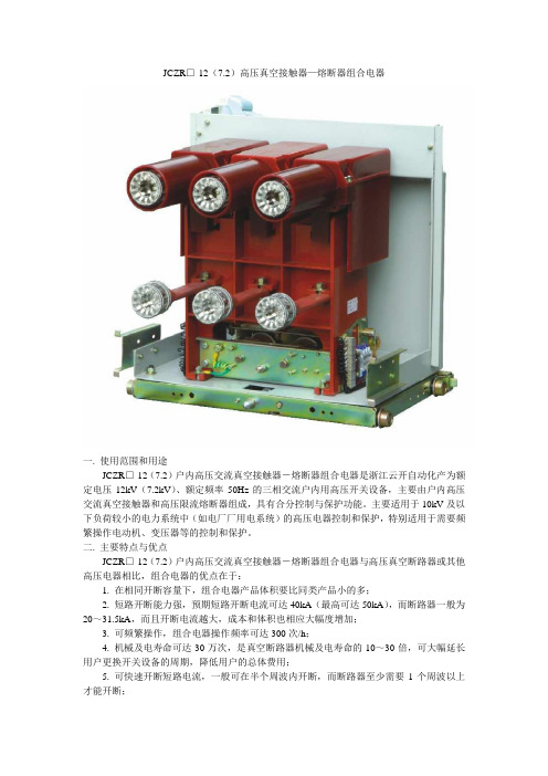
JCZR□-12(7.2)高压真空接触器—熔断器组合电器一. 使用范围和用途JCZR□-12(7.2)户内高压交流真空接触器-熔断器组合电器是浙江云开自动化产为额定电压12kV(7.2kV)、额定频率50Hz的三相交流户内用高压开关设备,主要由户内高压交流真空接触器和高压限流熔断器组成,具有合分控制与保护功能。
主要适用于10kV及以下负荷较小的电力系统中(如电厂厂用电系统)的高压电器控制和保护,特别适用于需要频繁操作电动机、变压器等的控制和保护。
二. 主要特点与优点JCZR□-12(7.2)户内高压交流真空接触器-熔断器组合电器与高压真空断路器或其他高压电器相比,组合电器的优点在于:1. 在相同开断容量下,组合电器产品体积要比同类产品小的多;2. 短路开断能力强,预期短路开断电流可达40kA(最高可达50kA),而断路器一般为20~31.5kA,而且开断电流越大,成本和体积也相应大幅度增加;3. 可频繁操作,组合电器操作频率可达300次/h;4. 机械及电寿命可达30万次,是真空断路器机械及电寿命的10~30倍,可大幅延长用户更换开关设备的周期,降低用户的总体费用;5. 可快速开断短路电流,一般可在半个周波内开断,而断路器至少需要1个周波以上才能开断;6. 安装更换方便,无需太多的改动即可用于普通的KYN28-12中置柜。
三. 使用环境要求3.1 周围空气温度:-15℃~+40℃,且24h内测得的温度平均值不超过35℃。
3.2 海拔:JCZR□-7.2J(D) 型用于额定电压7.2kV系统时1000m及以下地区;用于额定电压3.6kV系统时3000m及以下地区。
JCZR□-12J(D) 型用于额定电压12kV系统时1000m及以下地区;用于额定电压7.2kV系统时3000m及以下地区。
3.3 周围空气没有明显的受到尘埃、烟、腐蚀性气体、蒸汽或盐雾的污染。
3.4 湿度相对湿度:日平均值不大于95%,月平均值不大于90%;水蒸气压:日平均值不大于2.2kPa,月平均值不大于1.8kPa 。
JCZR5说明书
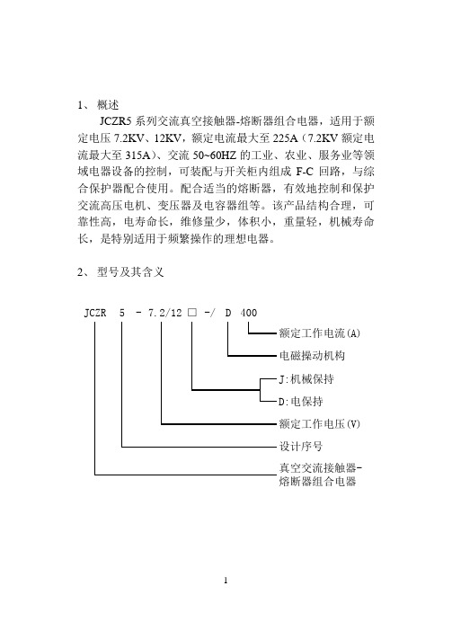
1、 概述JCZR5系列交流真空接触器-熔断器组合电器,适用于额定电压7.2KV 、12KV ,额定电流最大至225A (7.2KV 额定电流最大至315A )、交流50~60HZ 的工业、农业、服务业等领域电器设备的控制,可装配与开关柜内组成F-C 回路,与综合保护器配合使用。
配合适当的熔断器,有效地控制和保护交流高压电机、变压器及电容器组等。
该产品结构合理,可靠性高,电寿命长,维修量少,体积小,重量轻,机械寿命长,是特别适用于频繁操作的理想电器。
2、 型号及其含义400JCZR5-7.2/12□-/D3、使用环境条件3.1环境温度:周围空气温度最高不超过+10℃,最低不低于-25℃;3.2 海拔高度:安装地点的海拔高度不超过1000米;3.3 相对湿度:日平均值不大于95%,月年平均值不大于90%;3.4工作环境:无雨雪侵蚀、明火、爆炸危险、化学腐蚀及强烈震动的场合;3.5 污染等级:Ⅲ级;3.6 安装条件:安装平面与水平面的倾角不大于5°;注:当用户的使用环境、条件与上述不符时,请用户提出其具体要求,本公司可为用户进行特殊设计,尽可能满足用户的需求。
4主要技术参数(见表1)表一5、结构、功能5.1 JCZR5组合电器主要有真空接触器、高野限流熔断、底盘车、58芯航空插座等组合而成。
真空接触器主要有真空灭弧室、操作机构、控制电磁铁、控制电源及其它辅助部件构成;高压限流熔断主要有熔断器盒、支架及熔断器等组成;底盘车主要有推进机构、连锁机构、手柄等部件组成。
5.2 JCZR5组合电器可配装于KYN系列高压柜中,配柜宽650、800mm两种。
动触头中心距和外形尺寸详见图1、图2。
5.3 JCZR5组合电器控制方式有机械保持和电保持两种。
机械保持是合闸锁扣装置使接触器保持合闸状态,分闸电磁铁得电动作后,使分闸锁扣解扣,有分闸弹簧驱动操作机构完成分闸。
电保持是电磁铁完成合闸功能后仍然维持保持功能,切断电磁线圈的供电回路,由分闸弹簧驱动操作机构完成分闸。
unigear zvc金属封闭式开关设备 熔断器一接触器 安装使用说明书

—U n iG ea r Z V C 金属封闭式开关设备熔断器一 接触器—安装使用说明书UniGear ZVC 金属封闭式开关设备熔断器 一 接触器• 安全的防护能力• 卓越的产品质量• 灵活的解决方案•经济的运维成本— 目录005 006 006 007008 009 009 010 – 011 012 – 013 014 – 015 016 – 017 0181 概述2 标准和规范3 型式试验报告4 技术规范5 外形尺寸与重量6 收货与检查7 储存与检查8 基本结构9 安装10 操作11 维护12 故障处理• 开关设备只能安装于适合电气设备工作的户内场所• 确保由专业人员来进行安装、操作和维护• 必须保证安装、操作和维护过程符合标准和法规的要求• 严格遵守本操作手册的规定• 不要超出开关设备在正常工作条件下的额定参数• 确保操作人员可方便的得到本指导手册,且拥有能执行正确操作的技能• 应特别注意说明书中标有如下危险标志的注意事项正确可靠的操作确保您和他人的安全!如有任何需求,请联系ABB 客户服务人员。
—安全第一 !4U n i G e a r Z V C 金属封闭式开关设备 安装使用说明书UniGear ZVC 是三相交流,空气绝缘的户内开关设备,用于操作、控制和保护额定电压7.2 kV 及以下、额定电流400 A 及以下的电动机和变压器。
其它场合的应用,请与本公司协商确认。
UniGear ZVC 结构紧凑,易于维护,创造性的使开关柜小型、轻便,有效地地提高了配电室的空间利用率。
UniGear ZVC 外壳由2 mm 厚的热镀锌板制成。
结构设计形式为金属封闭式,防护等级为IP4X ,采用真空开断技术,以及将导体浇铸在环氧树脂内,确保开关柜具有较长的使用寿命。
开关柜内装有一个可关合短路电流的接地开关,所有的操作,即合-分-隔离-接地均可闭门操作,尽可能地确保当发生内部燃弧故障时的人身和设备安全,并且避免异物进人和电气绝缘下降对开关柜的影响。
交流接触器使用手册

第五章交流接触器5.1 用途和分类5.1.1 用途交流接触器是一种用于远距离频繁地接通和断开交流50Hz(或60Hz),电压至380V(或660/690V,有的主电路还可至1000V/1140V)的主电路及控制电路的电器,其主要控制对象是交流电动机,也可控制其他电力负载,如电热器、照明灯、电焊机、变压器和电容器组等。
直动式交流接触器控制的电动机主要是鼠笼式,由于其体积少,普遍用于机床行业中。
转动式交流接触器控制的电动机为绕线式,主要用于冶金、轧钢等企业及起重设备中。
5.1.2 分类5.1.2.1 按结构形式分a、直动式;b、转动式;5.1.2.2 按极数分:a、二极;b、三极;c、四极;d、五极;(只有转动式)5.1.2.3 按有无吹弧线圈分a、有吹弧线圈;b、无吹弧线圈;5.1.2.4 其他方式分(略)5.1.3 接触器的使用类别及典型负载5.1.3.1 使用类别见表5.1表5.1交流接触器的使用类别5.1.3.2典型负载不同的用电设备其负载性质和通断过程的电流变化相差很大,因此对接触器的要求也有所不同5.1.3.2.1 电热元件负载对电热元件负载中用的线绕电阻元件,其接通电流可达额定电流的1.4倍,例如用于室内供暖,电烘箱及电热空调等设备。
若考虑网络电压升高10%,则电阻元件的工作电流也将相应增大。
因此,在选择接触器的额定工作电流时,应予以考虑。
这类负载被划分在AC-1使用类别中。
5.1.3.2.2 照明装置当接通照明装置中的白炽灯负载时,有较大的冲击电流产生,约为额定电流的15倍,若考虑到容许电压升高10%,电流也将相应增加,其使用类别被划分在AC-5b中。
其他不同的照明灯,其接通时的冲击电流值和起动时间不同,负载功率因数也不等于1。
它们被划分在AC -5a 中。
5.1.3.2.3 低压变压器负载当接通低压变压器时,会出现一个持续时间甚短的峰值电流,可达变压器额定电流的15-20倍,它与变压器的绕组布置及铁心特性有关。
JCZ16使用说明书
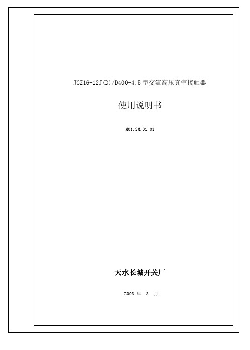
图3
图4
通止规:δ= . 、3 0 . 2 5 . 、35
JZ6 1J )/40 45 C1- 2(D D0 -. 型 交流高压真空接触器使用说明书M1S.10 0.M0.1
第 7 页 共 9页
图5 532 . . 触头超程 接触器处于合闸状态时,活节与拉杆之间的距离既触头超程 3 .,用图 4 ±0 5 量规插 入测量,如图 5 所示,若不符合要求则旋转拉杆上的螺母使超程值达到要求值见图。 5 4 运行及维护 . 接触器安装前应查看机器本身有无明显损坏,并通电进行合分闸操作;操作前应检 查操作电源电压的大小及类型是否与接触器的额定控制电源相符。 操作时若接触器因卡滞或其他原因拒合或拒分,应立即切断电源。否则会烧毁接触 器线圈,造成接触器损坏。 绝缘试验时,应注意不要加过高电压,以免造成壳体击穿损坏; 接触器不能长期带过负荷运行; 接触器在运行过程中应定期进行检查; 接触器与高压熔断器的具体使用方法和要求,参考我厂 F C回路技术要求和使用说 明书。 6 包装、运输、验收、保管 6 1 接触器在出厂前应经过检验,检验合格后方可包装、运输; . 62接触器及其辅助设备包装储运图示标志应符合 G11规定,运输包装收发货标志应符 . B9 合 G/68 规定; BT38 63真空接触器包装箱外侧应标有“小心轻放”“向上”“怕湿”等作业标志及有关收发 . 、 、 货标志;
M1S.10 0.M0.1
第 4 页 共 9页
额定控制电源电压:A2 0 A 10 D 2 0 D 10 C2 V C 1V C 2V C1 V 机械寿命: 电寿命: 触头开距: 超程: J 型 1 万次, 0 D 型 3 万次 0
1 万次 0
+ 60 1
3 . ±0 5
触头最大允许磨损量:3 m m 辅助开关控制容量: A 10 V ,D 9 W C 00 A C 0
快速作用陶瓷体类JCJSeries熔断器说明说明书
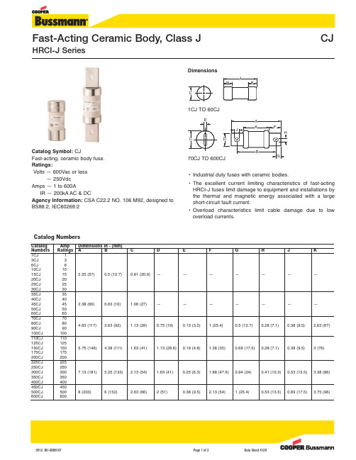
Catalog Symbol:CJFast-acting, ceramic body fuse.Ratings:Volts — 600Vac or less— 250Vdc Amps — 1 to 600AIR — 200kA AC & DCAgency Information:CSA C22.2 NO. 106 M92, designed to BS88:2, IEC60269:2•Industrial duty fuses with ceramic bodies.•The excellent current limiting characteristics of fast-acting HRCI-J fuses limit damage to equipment and installations by the thermal and magnetic energy associated with a large short-circuit fault current.•O verload characteristics limit cable damage due to low overload currents.0512 BU-SB98107Page 1 of 2Data Sheet 4129DimensionsEnergy Let-Through Curves ©2012 Cooper Bussmann 0512 BU-SB98107Page 2 of 2Data Sheet 4129The only controlled copy of this Data Sheet is the electronic read-only version located on the Cooper Bussmann Network Drive.All other copies of this document are by definition uncontrolled.This bulletin is intended to clearly present comprehensive product data and provide technical informa-tion that will help the end user with design applications.Cooper Bussmann reserves the right,without notice,to change design or construction of any products and to discontinue or limit distribution of any products.Cooper Bussmann also reserves the right to change or update,without notice,any technical information contained in this bulletin.Once a product has been selected,it should be tested by the user in all possible applications.。
CJ12系列交流接触器 说明书

B1 适用范围CJ12系列交流接触器CJ12系列及派生的CJ12Z系列交流接触器主要用于交流50Hz,额定工作电压至380V、额定工作电流至600A的电力线路中,供冶金、轧钢企业起重机等的电气设备中,作远距离接通和分断电路,并作为交流电动机频繁地起动、停止、反向和反接之用。
CJ 12 □-□/□3.1 周围空气温度为:-5℃~+40℃,24小时内其平均值不超过+35℃。
3.2 海拔高度:不超过2000m。
3.3 大气条件:最高温度为+40℃时,空气相对湿度不超过50%;在较低温度下可以允许有较高的相对湿 度,例如20℃时达90%。
对由于温度变化偶尔产生的凝露应采取特殊的措施。
3.4 污染等级:3级。
3.5 安装类别:Ⅲ类。
3.6 安装条件:安装面与垂直面倾斜度不大于±5°。
3.7 冲击振动:产品应安装和使用在无显著摇动、冲击和振动的地方。
4.1 技术参数与性能(见表1)。
4.2 接触器适用于下述工作制:4.2.1 8小时工作制;4.2.2 断续周期工作制,负载因数为40%(4、5极接触器仅适用于此工作制);4.2.3 短时工作制。
4.3 吸引线圈规格:交流:50Hz:127V、220V、380V;直流:110V、220V;4.4 动作特性:吸合电压:(85%~110%)Us;释放电压:交流(20%~75%)Us,直流(10%~75%)Us。
交流380V1000VA直流220V90WCJ12-150CJ12-250CJ12-400CJ12-60038038038038015025040060015025040060015025040048030030010010015151010600600300300常开234510RT16-315RT16-400RT16-500RT16-630表165注:1、机械寿命:二极产品应不少于1×10次,四、五极产品应不少于1×10次;2、电寿命:三极产品按AC-3和AC-4使用类别以及二、四、五极产品按AC-2使用类别的电寿命指标 由供需双方另行商定;3、CJ12Z系列直流控制交流接触器最大电流规格至400A,且该系列直流控制交流接触器产品本体 已 占用一对常闭辅助触头。
断路器培训演示稿-精品文档

4.2 结构特点 JCZR16-7.2型组合电器主要由高压真空接触器、熔断器、底盘车 三大部分组成。 4.2.1 真空接触器的结构
a) 回路额定电压等级为3.6~12kV; b) 结构简单合理、便于装配。 高、低压回路呈前后布置,动力传 动采用T型杠杆传动,操作动力合闸为电磁铁。 c) d) 精心选择控制回路元器件。 内 置 中 间 继 电 器 为 SIMENS 的 3TH80, 辅 助 触 头 选 用 SIMENS的3TF, 接线端子采用PHOENIX生产的回拉式弹簧接线 端子,该端子可接线方便可靠。
d) 合闸电磁铁的特殊设计 电保持真空接触器合闸线圈采用双绕组结构。其中安 匝数大的绕组为真空接触器合闸操作提供电磁力,安匝数 小的绕组为真空接触器长期保持在合闸状态提供电磁力。 保持绕组功率约为 15W ,而 3TL6 型仍采用的传统方案是 在合闸回路加经济电阻,功率约为100W。显然这一设计更 为合理,减小了真空接触器的功耗,并避免了经济电阻发 热带来的不利因素。 e) 设置有海拔高度调节器。 h) 真空接触器的机械特性及参数完全由零件加工精度来保证, 除超程外其余参数无需调整。
控制电源电压
DC : 220V 、 110V AC :220V 、110V
JCZR16-7.2J(D)型系列组合电 器的主要技术参数
额定电压 额定电流
7.2 kV 25-315 A
1min工频耐受电压 32 kV 预期短路关合电流(峰值)130 kA 预期短路开断电流 50 kA
四、结构特点
4.1 JCZR16-7.2J(D)型组合电器结构特点 a) 手车式结构、定位精度高。主要配用于柜宽 650mm的 KYN28A型开关柜中,。该柜与断路器柜相比,除柜宽、触头盒 及触头盒安装位置作了改动外,其余尺寸均不做改动。主母线 位置及柜体其它尺寸与KYN28型断路器柜一致。 b) 熔断器便于更换。 c) 外观美观。 d) 操作界面、联锁功能与KYN28A型断路器柜一致。 e) 实现各项联锁功能。
高压真空接触器高压限流熔断器组合电器
高压真空接触器——高压限流熔断器组合电器在发电厂中的应用无锡市蓝虹电子有限公司沈兴元副总工程师[摘要]本文介绍了高压真空接触器,高压限流熔断器的技术特性,以及两者在电厂内控制系统中的选配原则,并得出在1600KV A及以下的变压器回路、1200kW及以下的高压电动机回路和1200KVar及以下的电容器组,更适用于使用高压真空接触器加熔断器组合电器,超出此范围则使用断路器。
[关键词]高压真空接触器、高压限流熔断器、电动机、变压器、电容器。
1、序言随着我国经济建设的快速发展,对电力的需求越来越多,特别是去年夏天全国出现电荒后,现已演变成全年性全天候的缺电状况。
由此全国各地纷纷上马建设发电厂。
在发电厂的厂用高压用电系统中,现在大都设计成高压限流熔断器(F)和高压真空接触器(C)回路,以下简称F-C回路。
我公司去年仅F-C回路单元销售800套,今年已有500套的订单合同。
所以本文就高压真空接触器、高压限流熔断器和高压电动机、变压器、电容器的选用配合和保护等问题逐一介绍和分析。
2、高压真空接触器高压真空接触器在F-C回路中作为操作元件,由于其有特殊的结构,特别适用于需大量分闸、合闸操作循环的场合,是频繁操作的理想电器。
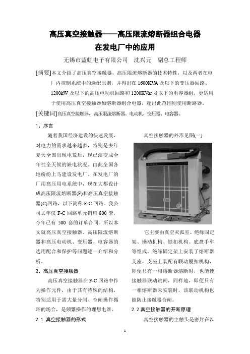
2.1 真空接触器的形式真空接触器的外形见图(一)它主要由真空灭弧室、绝缘固定架、操动机构、锁扣机构、底盘手车等组成,绝缘固定架上安装了熔断器支座,支座上装配有联动脱扣机构,即便只有一相熔断器熔断时,也能使接触器联动跳闸,同样地,即便只有一相熔断器未安装时,该联动机构也能防止接触器合闸。
2.2真空接触器的开断原理真空接触器的主触头是密封在以陶瓷为外壳的真空灭弧室中,灭弧室中的真空度高达1.33×10⁻⁴Pa。
当真空接触器分闸时,真空灭弧室中的动、静触头快速地开断,在分闸过程中,在高温触头之间产生的金属蒸气使电弧持续到电流第一次过零点,在电流过零点时,金属蒸气迅速凝结,使动静触头之间重新建立起很高的电介质强度,维持很高的瞬态恢复电压值,实现对开断电流的完成。
负荷开关说明书

一、概述电气设备的保护和控制用。
其中负荷开关—熔断器组合电器与变压器保护特性相匹配,对环网供电单元尤其适用。
环境湿度:日平均相对湿度:≤95% 月平均相对湿度:≤90%日平均蒸气压:≤2.2×10⁻³Mpa 月平均蒸气压:≤1.8×10⁻³MPab)海拔高度:不超过1000m;c)地震烈度不超过8度;d)使用场所无滴水、无结霜、无结露、无易燃和爆炸危险、无化学腐蚀性气体以及无剧烈震动。
若有特殊要求,请用户和我公司联系!四、本产品符合GB3804-1990、GB3906-1991、GB16926-1997、GB/T11022-1999、IEC420-1990等标准,并已通过了全部型式试验。
七、FL(R)N36-12 D型SF6负荷开关1 2 34 5 6 7注:1、上接线端头。
2、上壳体。
3、操作机构。
4、下接线端头。
5、电显输出端。
6、下壳体。
7、固定螺栓。
八、操作机构(一)、二工位手动操作机构1 2 3 4 5注:1、SF6开关合、分指示。
2、门连锁操作孔。
3、门连锁机构。
4、操作手柄。
5、合、分闸操作孔。
(二)、三工位手动操作机构1 2 3 4 56注:1、合、分指示。
2、门连锁操作孔。
3、门连锁机构。
4、操作手柄。
5、SF6开关合闸操作孔。
6、分闸按钮。
(三)、二工位电动操作机构(四)、三工位电动操作机构1 2 3 4 5 1 2 3 4 56 7 6 7 8注:1、辅助接点。
2、合、分闸指示。
注:1、辅助接点。
2、SF6开关合、分闸指示。
3、连锁机构。
4、接地开关操作孔。
3、连锁机构。
4、接地开关操作孔。
5、操作手柄。
6、储能电机。
5、操作手柄。
6、储能电机。
7、手动合、分闸操作孔。
7、手动合闸操作孔。
8、分闸按钮。
九、操作程序FL(R)N36-12□型负荷开关出厂前,经过严格的出厂检验,符合产品的技术要求。
在安装、调试前,必须仔细的阅读安装使用说明书,并做好以下准备工作。
接触器使用说明书

目录1 概述 (2)1.1 总则 (2)1.2 可提供的形式 (2)1.3 应用领域 (2)1.4 依据标准 (2)1.5 使用条件 (2)1.6 主要技术特性 (3)1.7 结构及原理 (3)1.7.1 主体结构 (3)1.7.2 灭弧原理 (4)1.7.3 动作原理 (4)2 熔断器选用说明(仅供参考) (4)2.1 熔断器 (4)2.2 电动机保护熔断器的选用 (4)2.3 变压器保护熔断器的选用 (4)2.4 熔断器使用 (5)3 技术参数.............................. 5 3.1 技术参数 (5)3.2 机械特性参数 (6)3.3 操动机构技术参数 (6)4. 外形尺寸 (7)4.1 固定式接触器 (7)4.2 手车式接触器 (7)5 电气原理图 (8)5.1固定式接触器的电气原理图 (8)5.2 手车式接触器的电气原理图 (9)5.3 图中所表示的操作状态 (11)5.4 说明 (11)6 安装、调试与操作 (11)7 维护与保养 (12)8 运输与储存 (12)9 随机文件及附件 (13)10 订货须知 (13)11 安全注意事项 (13)1 概述1.1 总则由澳大利亚通用电气设备有限公司生产的新一代电磁操动机构的三相接触器——VCR193真空接触器,主要用于额定工作电压12kV以下,额定频率50Hz/60Hz的三相交流系统中需要大量分、合闸操作循环的场合,同时又是特别适用于频繁操作的理想电器。
VCR193真空接触器主要由真空灭弧室、电磁操动机构以及其它辅助部件构成。
通过电磁操动机构控制来实现接触器的合闸操作,分闸操作则由分闸弹簧实现。
其结构紧凑、在无需经常维护的条件下仍保证其长久的电气和机械寿命。
VCR193真空接触器与旧系列的接触器有着良好的互换性,同时它附件的通用性强,易于组装成不同的配置。
1.2 可提供的形式VCR193真空接触器具有电气自保持和机械自保持两种配置,可提供以下两种结构形式:⏹固定式⏹手车式(配置熔断器支座)手车式接触器主要由固定式接触器和特定的底盘手车组成。
接触器熔断器组合电器中文安装使用说明书样本

7.2J(D) JCZR16-JCZR16-型系列12J(D)接触器-熔断器组合电器使用说明书M02(M03).SM.01.01天水长城开关厂年8 月警告: 在安装和使用本组合电器之前, 请仔细阅读本使用说明书。
不妥当的安装与使用将导致产品质量的下降甚至危及人身安全!目录1 概述 (3)2 技术数据 (3)2.1主要技术参数 (3)2.2接触器装配调整后,其机械特性参数应符合表2数据 (3)2.3分、合闸线圈的技术数据见表3 (4)3 使用环境要求 (4)4 产品结构及工作原理 (4)4.1产品结构 (4)4.2工作原理 (4)5 搬运 (6)5.1拆除包装箱 (6)5.2室内搬运 (6)6 安装 (6)7 检查 (9)7.1检查紧固件 (9)7.2操作检查 (9)7.3测试接触器机械特性参数 (9)7.4回路电阻检查 (9)7.5绝缘水平检查 (9)8 操作 (9)8.1操作手车进出车 (9)8.1电动操作接触器 (9)8.2联锁 (10)8.1手动分闸操作 (10)9 维护 (10)9.1经常性的检查 (10)9.2清洁 (10)9.3维护时的注意事项 (10)10 产品提供下列随机文件: (10)11 产品备件根据订货合同提供。
(10)1 概述本组合电器可配装于开关柜内组成F-C回路, 与综合保护装置配合使用。
供发电厂及工矿企业用来关合、开断交流高压电动机、变压器、电容器等负载用, 并具有过载、短路保护的功能。
本断路器能够使用在交流50Hz的三相电力系统中。
2 技术数据2.1 主要技术参数见表1表12.2 接触器装配调整后,其机械特性参数应符合表2数据表22.3 分、合闸线圈的技术数据见表3表33 使用环境要求a) 周围空气温度: +40℃~-15℃,且24h内测得的温度平均值不超过35℃b) 海拔: JCZR16-7.2J(D) 型用于额定电压7.2kV系统时1000m及以下地区;用于额定电压3.6kV系统时3000m及以下地区。
长征ZV说明书

绝缘筒上装有转换选择器静触头和选 择开关静触头,导流环及接线头、触头等 与绝缘筒之间的密封,均采用 0 型密封圈。 2.2.3 筒底
筒底由塑料压制而成,其上有 4 只均 布的耳攀,用来与绝缘筒连接,筒底中心 有一衬套嵌件,既作为操作轴底部轴承座 的固定支撑,又是抽油管插入的定心孔。 衬套下部装一放油螺钉,拧松螺钉,油即 泄出。放油螺钉与筒底之间用密封圈密封。 2.3 电动机构及其控制器,其它配套组件 2.3.1 电动机构及其控制器
本使用说明书适用于下列所有规格的 分接开关。
三相分接开关: ZVIII350Y,ZVIII500Y ZVIII350D,ZVIII500D 单相分接开关: ZVI350,ZVI700
1.1 产品型号说明
ZV Ⅲ 350 Y-72.5-10193W
基本接线图 设备最高电压(kV) 开关联结方式 最大额定通过电流(A) 相数(Ⅲ、Ⅰ) 型号
本说明书以四种方式强调一些安全须知上的重要事项
警告 当忽视某条要求会造成操作人员人生伤害时,给出“警告”字样。这是对生
命和健康有一定危险的警示,忽视这种警示可能导致严重的或致命的伤害。 当心
当忽视某条要求会导致对设备的损坏时,给出“当心”字样。这是对本装 置或用户的其他设备有一定危险的警示,但不排除有严重的或致命伤害。 注意
ZV 有 载 分 接 开 关 技 术 性 能 符 合 GB10230.1-2007 《分接开关 第 1 部分: 性能要求和试验方法》要求。符合 IEC60214-1:2003《分接开关 第 1 部分: 性能要求和试验方法》要求。
断路器培训 (2)ppt课件

一、综述
•
F-C回路是指熔断器(fuse)与接触器(contactor)以及综合 保护继电装置组合在一起的组合体。它在国家标准GB/T 14808中 被称作综合起动器。它具有寿命长、可频繁操作、功能合理、造 价低、噪声小、占地面积小等优点,越来越多的发电厂及工矿企 业采用高压接触器、熔断器、及电动机保护装置组成的综合起动 器来控制、保护高压电动机、变压器、感应炉等负载。
二、产品发展现状及开发背景
•
国外早在70年代就在高压电动机及变压器的供电系统中采 用了F-C综合起动器。我国从90年起开始研制高压接触器及综合起 动器,至今已有上万台高压综合起动器在运行中。高压综合起动 器的结构形式也先后经历了KYN、JYN单层柜、双层柜、左右柜的 一 个逐 步成熟 的过 程,目 前左 右柜使 用得 较多。 最近 几年, KYN28型中置式高压开关柜因其具有外型美观、维修方便、性能可 靠、进出车灵活等优点,在国内得到了较为广泛的运用。越来越 多的用户提出需要与KYN28型高压真空断路器柜能并柜使用的高压 综合起动器柜。
三、主要技术参数
•
JCZR16-7.2J(D)型接触器-熔断器组合电器的设计及试验采用了最新版的 国家标准GB/T 14808《交流高压接触器和基于接触器的电动机起动器》, 其中高压真空接触器主要技术参数见表: 型号及意义 J C Z 16 – 12□ / D 400 - 4.5 接触器 真空 设计序号 额定电压(kV) 极限开断电流(kA) 额定电流 (A)
控制电源电压
DC : 220V 、 110V AC :220V 、110V
JCZR16-7.2J(D)型系列组合电 器的主要技术参数
接触器说明书-V5

目录1.关于使用快插式接触器模块的信息 (4)2. 规则 (4)3. 规程 (5)4. 防爆类型 (5)5. 技术数据 (5)5.1 快插式接触器模块HPC450-1-V5 (5)5.2 快插式接触器模块HPC450-3-V5 (5)5.3 漏电闭锁 (6)5.4 绝缘监测 (6)5.5 中性点绝缘电网中先导回路监测 (7)5.6 PTC温度测量电路 (7)5.7 PT100温度测量电路 (7)5.8 过载和短路保护装置 (8)6. 综述 (8)6.1 主回路结构 (8)6.2 监测和控制装置综述 (9)6.2.1 保护模块MPE综述 (9)6.2.2 PDIM-2D-GBA显示和输入输出继电器模块 (10)6.2.3显示器模块DIS-2D描述 (11)6.2.4 输入/输出继电器模块IM-2D描述 (13)6.3 并行控制 (17)6.3.1 先导回路控制-自复位按键操作 (17)6.3.2 先导回路控制-单节点旋钮操作 (19)6.3.3 输入/输出继电器模块操作-单节点自锁开关操作 (20)6.4 串接到高级控制系统 (21)7. 操作 (22)7.1 显示器模块DIS-2D描述 (22)7.2 菜单种类 (23)7.2.1 电工菜单 (23)7.2.2 工程师菜单 (25)7.2.3 使用者菜单 (33)7.2.4 服务菜单 (40)7.3 错误信息显示 (52)8. 监测功能描述 (59)8.1 过载分断 (59)8.2 短路分断装置 (61)8.3 相平衡 (62)8.4 绝缘监测(ESA) (62)8.5 漏电闭锁 (63)8.6 温度监测(PTC热敏电阻和PT100) (64)8.6.1 PTC温度监测 (64)8.6.2 PT100温度监测 (65)8.7 先导回路监测 (65)8.8 中性点漂移(中性点接地电网中故障电流监测) (67)8.9 高压测试(只用于3.3kV接触器模块) (68)8.10 并行操作时的电流监测 (69)9. 安全回路功能 (70)10. 短路分断实验 (70)1.关于使用快插式接触器模块的信息为了正确使用该模块必须注意下列各点:快插式接触器模块必须安装在隔爆腔室中使用。
JCZR16-12接触器-熔断器组合电器中文安装使用说明书

7.3 测试接触器机械特性参数 ..................................................................................................................... 9
7.4 回路电阻检查 ......................................................................................................................................... 9
JCZR16 型系列接触器-熔断器组合电器 使用说明书
M02(M03).SM.01.01
第 3 页 共 13 页
1 概述 本组合电器可配装于开关柜内组成 F-C 回路,与综合保护装置配合使用。供发电厂及
工矿企业用来关合、开断交流高压电动机、变压器、电容器等负载用,并具有过载、短路
保护的功能。本断路器可以使用在交流 50Hz 的三相电力系统中。
8 操作 ......................................................................................................................................................... 9
电源接触器电源接触器替换指南说明书
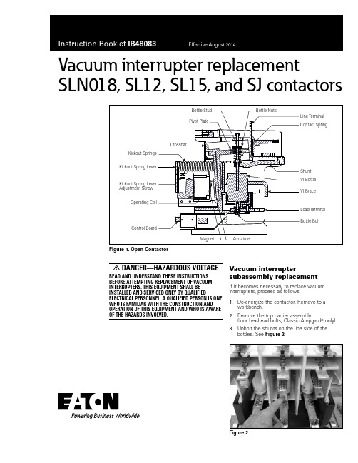
Vacuum interrupter replacement SLN018, SL12, SL15, and SJ contactorsFigure 1. Open ContactorDANGER—HAZARDOUS VOLTAGE READ AND UNDERSTAND THESE INSTRUCTIONS BEFORE ATTEMPTING REPLACEMENT OF VACUUM INTERRUPTERS. THIS EQUIPMENT SHALL BE INSTALLED AND SERVICED ONLY BY QUALIFIED ELECTRICAL PERSONNEL. A QUALIFIED PERSON IS ONE WHO IS FAMILIAR WITH THE CONSTRUCTION AND OPERATION OF THIS EQUIPMENT AND WHO IS AWARE OF THE HAZARDS INVOLVED. Vacuum interrupter subassembly replacementIf it becomes necessary to replace vacuum interrupters, proceed as follows:1. De-energize the contactor. Remove to aworkbench.2. Remove the top barrier assembly(four hex-head bolts, Classic Ampgard T only).3. Unbolt the shunts on the line side of thebottles. See Figure 2.Figure 2.2Instruction Booklet IB48083Effective August 2014Vacuum interrupter replacementSLN018, SL12, SL15, and SJ contactorsEATON 4. Remove control transformer primary fuses(Classic Ampgard only).5. Remove the hollow screw above each interrupter.6. Remove the bottle nuts from the top stems, using a screwdriveras shown in Figure 3. Set aside the screws, nuts, and washers.Figure 3.7. Remove the two 5/16-inch bolts attaching each bottlesubassembly. Set bolts aside.8. Withdraw the interrupter subassemblies from the contactorchassis, pulling the bottom end out first so that the top stud clears the rear frame of the chassis. The contact springs are loose at this point and should be captured and stored. The bottle subassembly consists of the interrupter, shunt, and related hardware. See Figure 1.9. Remove the old pivot plate from the crossbar. Retain hardware.10. Loosen and remove the bottle bolt that holds the copper conduc-tor to the bottom of the interrupter. Retain the shim from under the copper conductor and the copper spacer.CAUTIONAT NO TIME DURING THE INSTALLATION OF THE NEW INTERRUPTERSHOULD TORQUE BE APPLIED TO THE MOVING END OF THE INTERRUPTER. INTERNAL DAMAGE MAY RESULT IF TORQUE IS APPLIED. THE USEDINTERRUPTERS SHOULD BE DESTROYED. DESTROYING THE INTERRUPTERS WILL ENSURE THAT THEY ARE NOT LATER CONSIDERED NEW AND INSTALLED IN ANOTHER CONTACTOR.11. Install the new pivot plate (provided with the new interrupter kit)on the crossbar.12. Fasten the previously removed copper conductor to the newinterrupter with the shim between the mold frame and the copper conductor. The bottle spacer is installed between the interrupter and the copper conductor. Do not tighten the bolt at this time.13. Preset the shunt by bending the free end in a smooth curve totouch the stud, then release.14. Install contact springs and cups onto the top stems, with cup ontop, flange down. See Figure 4.Figure 4.15. Insert bottle subassemblies into chassis, putting top end infirst and guiding the bottle stud into the slot in the pivot plate. Check to confirm that the spring and cup are between the interrupter and the crossbar.16. Bolt the subassembly to the chassis, using the 5/16-inch bolts,two per pole.17. Align the interrupter on the copper conductor (the bottle bolt isloose) until the stud does not rub or touch the slot in the hole in the pivot plate. Tighten the bottle bolt. See Figure 3. Check alignment again to make sure it was maintained while tightening.18. Attach shunts to the line side conductor.19. Recheck to make sure that the bottle studs remain clear of thepivot plate. In particular, make certain that the shunts have a slight bow downward (from Step 12) and do not push the bottle studs against the pivot plate. If they do touch the pivot plate, loosen the shunts from the line side conductor and repeat Step 12 before refastening.20. Close the contactor by applying rated voltage from an isolatedpower source, using adequate care against electrical shock. 21. Install two bottle nuts, plus the two flat washers previouslyremoved, onto the center pole bottle stud. Both bottle nuts must have their threaded flanges facing UP.3Instruction Booklet IB48083Effective August 2014Vacuum interrupter replacementSLN018, SL12, SL15, and SJ contactors EATON 22. Turn the center pole bottle nuts clockwise until they are0.120 ± 0.005 inches from the pivot plate. This is the overtravel gap. See Figure 5. Lock the bottle nuts with a screwdriverinserted from the front of the frame molding, turning the screw-driver counter-clockwise with the blade fitted from a notch in one bottle nut across to a notch in the other bottle nut. See Figure 3.Figure 5. Closed Contactor23. De-energize the coil and remove the power source.24. Note and record the length of the kickout springs. Loosen theset screw that locks the kickout spring adjusting screw, then loosen the kickout spring adjusting screw until the contacts of the center pole barely touch, using a volt-ohmeter or test light as an indicator of touch and open.otee:N Whenever adjusting the kickout spring lever, put your free hand over the kickout springs as a precaution.25. With the contactor in this position and the center contacts justtouching, install and adjust the bottle nuts (and spacing washers) on the other two poles so that these two poles make contact simultaneously with the center pole when checked with a meter or test light. Lock the bottle nuts as before. 26. Install the hollow screws through the guide bar onto the threebottle studs.27. Tighten the kickout spring adjusting screw back to the originalcompressed length of the kickout springs. Check that the arma-ture rests firmly against its stop on the molded frame. When a screwdriver is pushed against the bottom end of the armature in the open position, the armature must not move. If it does, the kickout springs should be tightened further to push the armature to a solid position. Re-tighten set-screw. Do not overtighten.28. Install control transformer primary fuses (Classic Ampgard).29. Install top barrier assembly (Classic Ampgard).OvertravelBottle NutsPivot PlateEaton1000 Eaton Boulevard Cleveland, OH 44122 United States © 2014 EatonAll Rights ReservedPrinted in USAPublication No. IB48083 / Z15482 August 2014Eaton is a registered trademark.All other trademarks are propertyof their respective owners.Vacuum interrupter replacement SLN018, SL12, SL15, and SJ contactorsInstruction Booklet IB48083 Effective August 2014。
合格电源系列熔断器安装说明书
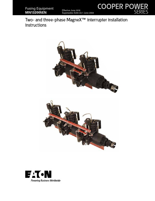
Two- and three-phase MagneX™ interrupter installation instructionsDISCLAIMER OF WARRANTIES AND LIMITATION OF LIABILITYThe information, recommendations, descriptions and safety notations in this document are based on Eaton Corporation’s (“Eaton”) experience and judgment and may not cover all contingencies. If further information is required, an Eaton sales office should be consulted. Sale of the product shown in this literature is subject to the terms and conditions outlined in appropriate Eaton selling policies or other contractual agreement between Eaton and the purchaser.THERE ARE NO UNDERSTANDINGS, AGREEMENTS, WARRANTIES, EXPRESSED OR IMPLIED, INCLUDING WARRANTIES OF FITNESS FOR A PARTICULAR PURPOSE OR MERCHANTABILITY, OTHER THAN THOSE SPECIFICALL Y SET OUT IN ANY EXISTING CONTRACT BETWEEN THE PARTIES. ANY SUCH CONTRACT STATES THE ENTIRE OBLIGATION OF EATON. THE CONTENTS OF THIS DOCUMENT SHALL NOT BECOME PART OF OR MODIFY ANY CONTRACT BETWEEN THE PARTIES. In no event will Eaton be responsible to the purchaser or user in contract, in tort (including negligence), strict liability or other-wise for any special, indirect, incidental or consequential damage or loss whatsoever, including but not limited to damage or loss of use of equipment, plant or power system, cost of capital, loss of power, additional expenses in the use of existing power facilities, or claims against the purchaser or user by its customers resulting from the use of the information, recom-mendations and descriptions contained herein. The information contained in this manual is subject to change without notice.ii TWO- AND THREE-PHASE MAGNEX INTERRUPTER INSTALLATION INSTRUCTIONS MN132005EN June 2015ContentsSAFETY INFORMATIONSafety Information (iv)PRODUCT INFORMATIONIntroduction (1)Acceptance and Initial Inspection (1)Handling and Storage (1)Quality Standards (1)ELECTRICAL RATINGSVoltage Ratings (1)Interrupting Rating (1)APPLICATION/OPERATIONApplication/Operation (2)OPERATION REQUIREMENTSOperation Requirements (2)INSTALLATIONInstallation Instructions (2)RECOMMENDED CLEARANCESMechanical . . . . . . . . . . . . . . . . . . . . . . . . . . . . . . . . . . . . . . . . . . . . . . . . . . . . . . . . . . . . . . . . . . . . . . . . . . . . . . . . . . . .5 Dielectric . . . . . . . . . . . . . . . . . . . . . . . . . . . . . . . . . . . . . . . . . . . . . . . . . . . . . . . . . . . . . . . . . . . . . . . . . . . . . . . . . . . . . .5MECHANICAL STRENGTHStrip Point of Housing Threads . . . . . . . . . . . . . . . . . . . . . . . . . . . . . . . . . . . . . . . . . . . . . . . . . . . . . . . . . . . . . . . . . . . . .6 Decal . . . . . . . . . . . . . . . . . . . . . . . . . . . . . . . . . . . . . . . . . . . . . . . . . . . . . . . . . . . . . . . . . . . . . . . . . . . . . . . . . . . . . . . . .6iii TWO- AND THREE-PHASE MAGNEX INTERRUPTER INSTALLATION INSTRUCTIONS MN132005EN June 2015Eaton meets or exceeds all applicable industry standards relating to product safety in its Cooper Power™ series products. We actively promote safe practices in the use and maintenance of our products through our service literature, instructional training programs, and the continuous efforts of all Eaton employees involved in product design, manufacture, marketing, and service.We strongly urge that you always follow all locally approved safety procedures and safety instructions when working around high voltage lines and equipment, and support our “Safety For Life” mission.iv TWO- AND THREE-PHASE MAGNEX INTERRUPTER INSTALLATION INSTRUCTIONS MN132005EN June 2015Product informationIntroductionEaton designs its Cooper Power™ series MagneX™ interrupter to be an over-current protective device that protects distribution transformers from damaging overloads and secondary faults, and is also used for switching the transformer “on” or “off”.Read this manual firstRead and understand the contents of this manual and follow all locally approved procedures and safety practices before installing or operating this equipment.Additional informationThese instructions cannot cover all details or variationsin the equipment, procedures, or process described nor provide directions for meeting every possible contingency during installation, operation, or maintenance. For additional information, contact your representative.Acceptance and initial inspectionEach MagneX interrupter is in good condition when accepted by the carrier for shipment. Upon receipt, inspect the shipping container for signs of damage. Unpack the MagneX interrupter and inspect it thoroughly for damage incurred during shipment. If damage is discovered, file a claim with the carrier immediately.Handling and storageBe careful during handling and storage of the MagneX interrupter to minimize the possibility of damage. If the MagneX interrupter is to be stored for any length of time prior to installation, provide a clean, dry storage area.StandardsISO 9001 Certified Quality Management SystemElectrical ratingsThe MagneX™ interrupter is designed to be operated in accordance with normal safe operating procedures . These instructions are not intended to supersede or replace existing safety and operating procedures .Read all instructions before installing the MagneX™ interrupter .The fuse should be installed and serviced only by personnel familiar with good safety practice and thehandling of high-voltage electrical equipment .1 TWO- AND THREE-PHASE MAGNEX INTERRUPTER INSTALLATION INSTRUCTONS MN132005EN June 2015Figure 1 . MagneX assembly – front/side/back views (with standard handle hardware kit) .ote:NDimensions given are for reference only, inches (mm)2TWO- AND THREE-PHASE MAGNEX INTERRUPTER INSTALLATION INSTRUCTIONS MN132005EN June 2015InstallationThe two- or three-phase MagneX interrupter is mounted through the transformer tank wall for side wall mount. Use 2.25" diameter hole size with anti-rotation nibs (.156" radius), refer to Figure 3. Nibs (either one or two) must be on the horizontal centerline of the tank hole ±5 degrees. Refer to Figures 4 and 5 to see how the unit should be installed and connected. The oil level should be 2" (minimum) above top of chamber. Sealing is accomplished with gasket on inside of tank and sealing nut on protruding threads through tank wall. The MagneX interrupter should be kept perpendicularwith the tank wall during installation (through the tank wall mounting hole from the inside of the tank) . This may require some type of support (inside tank) until the sealing nut is snug up against the tank wall . The sealing nut shall be tightened to snug plus 1/2 turn, (90-120in-Ibs, 10-14 Nm) .ote:N Snug is defined as the point at which the sealing nut no longer turns freely as the MagneX interrupter issupported.Figure 2 . Open/Closed handle positions (Standard positions shown) .Figure 3 . T ank mounting hole detail .ote:N Exterior mounting surface extending 1/2" outward from the tank hole outer edge shall be flat and clear ofsurface obstructions.3 TWO- AND THREE-PHASE MAGNEX INTERRUPTER INSTALLATION INSTRUCTONS MN132005EN June 2015Figure 5 . MagneX interrupter – typical installation indicating minimum oil level .Figure 6 . Arc clearance zone .CONNECTION POINT FOR ISOLATION LINK OR ELSP (PARTIAL RANGE CURRENT -LIMITING) FUSE (THE HIGH VOLTAGE LEAD IS CONNECTED TO THE OTHER ENDOF THE ISOLATION LINK OR ELSP FUSE).2.0" (50.8 mm)4TWO- AND THREE-PHASE MAGNEX INTERRUPTER INSTALLATION INSTRUCTIONS MN132005EN June 2015Recommended clearancesMechanical• External handle clear of obstruction. Clearances also required for handle movement swing. (Refer to Figure 2).Dielectric (under-oil)• Clouds of gas will rise during operation, so it is not recommended that other components be located above the MagneX interrupter, unless they are outside the arc clearance zone and have an insulated barrier between them that will deflect gas bubbles from the MagneX operation away from the component above the MagneX interrupter.The outline drawings shown in Figures 5 and 6 describe the MagneX interrupter and its application in oil-filled apparatus. This information should be used only by trained personnel familiar with the design requirements for oil-filled apparatus. This information is not intended as a substitute for adequate training and experience in such design. Should clarification or further information be required for the user’s purposes, contact your Eaton representative.All energized parts of the MagneX interrupter must be under oil and spaced away from other energized parts or ground with sufficient distance to withstand all operating and test voltages. In order for proper switch operation to occur, an arc clearance zone is required around the MagneX interrupter. This zone should be under oil and free of all foreign materials. The boundaries of this zone are defined in Figure 5. Mechanical strengthStrip point of housing threadsThe torque strength of the sealing nut and housing threads exceeds 400 in-lbs (45 Nm). This device requires no additional bracing or support, as it is fully self-supporting. The mechanical strength of the device exceeds the maximum stress from leads or interrupting functions.DecalA “Caution Decal” and “Warning Decal” are includedand should be located on the tank wall near the Magnex interrupter handle. (Failure to do so will constitute a waiver of all warranty and indemnity obligations attributed to Eaton).Recommended (minimum) under-oil clearances must be followed to avoid internal arcing which could result in component failure, property damage or possible severe personal injury .5TWO- AND THREE-PHASE MAGNEX INTERRUPTER INSTALLATION INSTRUCTONS MN132005EN June 2015This page is intentionally left blank.6TWO- AND THREE-PHASE MAGNEX INTERRUPTER INSTALLATION INSTRUCTIONS MN132005EN June 2015This page is intentionally left blank.7 TWO- AND THREE-PHASE MAGNEX INTERRUPTER INSTALLATION INSTRUCTONS MN132005EN June 2015Eaton1000 Eaton Boulevard Cleveland, OH 44122United StatesEaton’s Cooper Power Systems Division2300 Badger Drive Waukesha, WI 53188United States/cooperpowerseries© 2015 EatonAll Rights ReservedPrinted in USAPublication No. MN132005EN Rev 0 (Supersedes 5000050900 Rev 1)Eaton, Cooper Power, and MagneX arevaluable trademarks of Eaton in the U.S.and other countries. Y ou are not permittedto use these trademarks without the priorwritten consent of Eaton.For Eaton's Cooper Power series MagneXinterrupter product informationcall 1-877-277-4636 or visit:/cooperpowerseries.。
- 1、下载文档前请自行甄别文档内容的完整性,平台不提供额外的编辑、内容补充、找答案等附加服务。
- 2、"仅部分预览"的文档,不可在线预览部分如存在完整性等问题,可反馈申请退款(可完整预览的文档不适用该条件!)。
- 3、如文档侵犯您的权益,请联系客服反馈,我们会尽快为您处理(人工客服工作时间:9:00-18:30)。
7.3 测试接触器机械特性参数 ..................................................................................................................... 9
7.4 回路电阻检查 ......................................................................................................................................... 9
9 维护....................................................................................................................................................... 10
JCZR16 型系列接触器-熔断器组合电器 使用说明书
M02(M03).SM.01.01
第 3 页 共 13 页
1 概述 本组合电器可配装于开关柜内组成 F-C 回路,与综合保护装置配合使用。供发电厂及
工矿企业用来关合、开断交流高压电动机、变压器、电容器等负载用,并具有过载、短路
保护的功能。本断路器可以使用在交流 50Hz 的三相电力系统中。
7.1 检查紧固件 ............................................................................................................................................. 9 7.2 操作检查 ................................................................................................................................................. 9
警告:在安装和使用本组合电器之前,请仔细阅读本使用说明书。不
妥当的安装与使用将导致产品质量的下降甚至危及人身安全!
目录Leabharlann 1 概述......................................................................................................................................................... 3
4 产品结构及工作原理............................................................................................................................. 4 4.1 产品结构 ................................................................................................................................................. 4 4.2工作原理................................................................................................................................................... 4 5 搬运......................................................................................................................................................... 6 5.1 拆除包装箱 ............................................................................................................................................. 6 5.2 室内搬运 ................................................................................................................................................. 6 6 安装......................................................................................................................................................... 6
JCZR16-7.2J(D) JCZR16-12J(D) 型系列 接触器-熔断器组合电器
使用说明书
M02(M03).SM.01.01
天水长城开关厂
2004 年 8 月
天水长城开关厂
使用说明书
JCZR16 型 系列接触器-熔断器组合电器
M02(M03).SM.01.01 代替:
第 1 页 共 13 页
2 技术数据................................................................................................................................................. 3 2.1主要技术参数………………………………………………………………………………………….3 2.2接触器装配调整后,其机械特性参数应符合表2数据.......................................................................... 3 2.3分、合闸线圈的技术数据见表3............................................................................................................ 4 3 使用环境要求......................................................................................................................................... 4
10 产品提供下列随机文件: ................................................................................................................. 10
11 产品备件根据订货合同提供。 ......................................................................................................... 10
9.1 经常性的检查 ....................................................................................................................................... 10 9.2 清洁 .................................................................................................................................................... 10 9.3 维护时的注意事项 ............................................................................................................................... 10
8 操作 ......................................................................................................................................................... 9
资料来源
提出部门 标记 处数 更改文件号 签 字 日期 批准文号
编制 校核 规格审查 审定 批准
JCZR16 型系列接触器-熔断器组合电器 使用说明书
M02(M03).SM.01.01
第 2 页 共 13 页
7.5 绝缘水平检查 ......................................................................................................................................... 9
2 技术数据
2.1 主要技术参数见表 1
表1
序号
名
称
单位
数
1 额定电压
kV
7.2
2
额定绝缘水平
1min 工频耐受电压
kV
32
相间、对地、断口
