使用说明书安全开关SLK
SICK安全开关10LOCK-快速指引

1.3 插销的方向是可以调整的
Page 3 of 7 Version: V1.0 Nhomakorabea图1
Edit By: Jerry Tan
Service &Technical Support Hotline: 4000-121-000
广州市西克传感器有限公司 SICK China Sensor Co., Ltd.
广州市西克传感器有限公司 SICK China Sensor Co., Ltd.
苏州正雄自动化
i10 LOCK 快速指引
Page 1 of 7 Version: V1.0
Edit By: Jerry Tan
Service &Technical Support Hotline: 4000-121-000
3.1 i10-M(机械锁定)
⊙关闭和锁定: 将插销插入安全锁从而释放锁定门闩。 安全锁进入“actuator inserted-locked”状态如图 2。 ⊙解锁: 上电,安全锁解锁进入“unlocked“状态如图 2。 ⊙打开: 插销移出后,锁定门闩被阻塞住,“actuator withdrawn“状态如图 2,安全触点保持强制打开 状态。
-安全门打开时,机器操作人员应当很难触及到。 -可以使用手动释放机械机构;安全锁能够被检查到,并且能够更换。 -紧急释放可以在危险区域内侧使用。 注意: -不能使用安全锁来停止移动部件。 -只有满足组装条件时进行安装。
1.2 安装顺序
-将插销插进凸轮装置。 -可靠的安装安全锁。 -将插销与保护设备连接到一起,要保证连接的可靠行,可以使用只能单方向旋转的螺丝, 或者铆接焊接。 -安装附加的停止装置来停止移动部件(不能使用安全锁来停止移动部件)。
安全开关
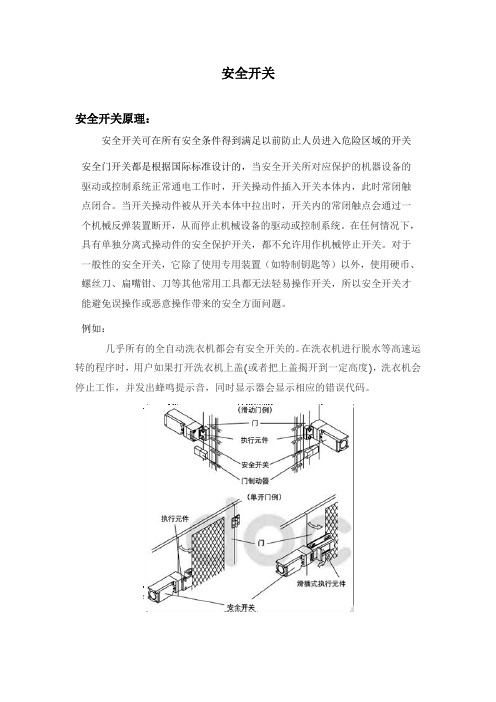
安全开关安全开关原理:安全开关可在所有安全条件得到满足以前防止人员进入危险区域的开关安全门开关都是根据国际标准设计的,当安全开关所对应保护的机器设备的驱动或控制系统正常通电工作时,开关操动件插入开关本体内,此时常闭触点闭合。
当开关操动件被从开关本体中拉出时,开关内的常闭触点会通过一个机械反弹装置断开,从而停止机械设备的驱动或控制系统。
在任何情况下,具有单独分离式操动件的安全保护开关,都不允许用作机械停止开关。
对于一般性的安全开关,它除了使用专用装置(如特制钥匙等)以外,使用硬币、螺丝刀、扁嘴钳、刀等其他常用工具都无法轻易操作开关,所以安全开关才能避免误操作或恶意操作带来的安全方面问题。
例如:几乎所有的全自动洗衣机都会有安全开关的。
在洗衣机进行脱水等高速运转的程序时,用户如果打开洗衣机上盖(或者把上盖揭开到一定高度),洗衣机会停止工作,并发出蜂鸣提示音,同时显示器会显示相应的错误代码。
安全开关种类:根据使用环境的不同,对安全开关的结构和性能要求也不同,所以市场上开发有各种不同的安全开关:插销式开关、安全磁开关、安全门锁开关、安全拉绳开关、紧急停止按钮、绞链连锁开关、安全使能开关、安全限位开关、防爆开关等其中每个系列又有不同产品类型,所以说,安全开关的种类非常丰富,可满足各领域的不同要求。
安全开关的使用领域:安全开关应用广泛,特别是一些安全要求很高的行业,如安全开关可广泛应用于汽车制造领域、冶金行业、金属加工设备、冲压设备、铸造设备、锻压机械、焊接设备、涂装设备、激光加工设备、包装印刷机械、橡胶塑料设备、切削机床、流水线设备、电梯、机器人和自动化设备。
安全开关防尘防水,抗震性强,使用寿命长,适用于标准机械工程及卫生要求严格的领域。
具体举例如:机床加工中心门防护拉伸包装机防护注塑机危险点防护传送机系统上的紧急停止监控生产线上的风门泡罩包装机上的门监控存储和检索系统上的安全位置监控制袋、充填、封口包装机的门监控博恩斯坦安全开关了解:博恩斯坦——Bernstein主要生产工业安全控制产品,如博恩斯坦限位开关、安全开关、接近开关、门锁开关、电梯门开关、拉绳开关、光电开关、脚踏开关、安全继电器、磁开关、传感器、控制箱等。
系列西克安全开关安全操作及保养规程
系列西克安全开关安全操作及保养规程1. 背景介绍西克安全开关是一种主要用于机器安全控制的装置。
它可以利用机械原理来保障工业场所内的设备、人员和环境的安全。
但是,在使用西克安全开关时,我们需要遵守一些安全操作规程和保养措施,以确保设备和人员的安全。
本文将简要介绍西克安全开关的安全操作规程和保养措施。
2. 安全操作规程2.1 安装和使用在安装和使用西克安全开关的过程中,需要遵守以下规程:•在安装和使用西克安全开关之前,必须了解其使用范围、技术参数和使用方法,并确保这些信息清晰明了地记录在文件中。
必要时,可寻求专业人员的帮助。
•西克安全开关应规范地安装在设备的合适位置,并应保持适当的连接稳定和柔性。
•在连接时,必须检查电压是否符合该设备的电气要求。
•应采取合适的安全措施来防止误操作和事故发生。
2.2 维护和操作在使用西克安全开关的过程中,需要遵守以下规程:•在每次使用前,必须对西克安全开关进行检查和维护,确保其状态正常并能正常工作。
•在使用过程中,必须防止西克安全开关空载或过载工作情况的发生。
•在使用过程中,必须确保西克安全开关处于可靠的状态。
如果西克安全开关损坏或存在问题,则必须立即停止使用,并进行修理或更换。
•在处理或维护西克安全开关时,必须按照相应的规程进行操作,以减少机器设备、人员和环境的风险。
3. 保养措施在使用西克安全开关的过程中,需要遵守以下保养措施:•定期检查西克安全开关的表面和内部,清理和除尘。
特别是在污染严重的环境中使用的设备,应定期进行清洗。
•对于机械部分,必须定期进行润滑或更换损坏的部件。
•在发现西克安全开关有渗漏现象时,必须立即检查并清理。
•在西克安全开关包含小型电路的情况下,必须保持电路的冷却条件。
4. 总结本文介绍了西克安全开关的安全操作规程和保养措施。
在使用和维护西克安全开关的过程中,必须遵循这些规则,以确保设备和人员的安全。
这些规则不仅适用于西克安全开关,也适用于其他类似装置的使用和维护。
安科龙LXK3系列行程开关使用说明书
L X K3系列行程开关符合标准:GB/T14048.5产品安装使用前,请仔细阅读使用说明书,并妥善保管,以备查阅。
-1-1 用途及适用范围LXK3系列行程开关(以下简称行程开关)适用于交流50Hz 或60Hz ,额定工作电压380V 或直流至220V 同极使用的控制电路及辅助电路中,作操纵、控制、限位及信号连锁用。
产品符合:GB/T 14048.5 标准。
行程开关具有外形美观,使用寿命长、动作灵活可靠、防护性能好、品种较多、适用范围广等特点。
2 型号含义Z L B T J D H1H2H3W柱塞式、自动复位滚轮柱塞式、自动复位可调滚轮转臂式、自动复位可调金属摆杆式、自动复位叉式、二轮在同一方向、不自动复位叉式、左轮在前、右轮在后、不自动复位叉式、右轮在前、左轮在后、不自动复位万向式、自动复位滚轮转臂式、自动复位弹性摆杆式、自动复位K S H无保护外壳、开启式元件竖式、底部有一出线孔横型、底部、两侧各有一出线孔基本规格代号:第一位数字表示触头对数,一常开一常闭触头,标记为“2”;第二位数字表示触头组合型式,一常开一常闭同极换瞬动触头标记为“0”设计序号快动行程开关LX K 3- □ □/□操作型式代号:保护外壳型式代号:表13 使用条件3.1 周围空气温度不超过+40℃,不低于-5℃,周围空气温度24小时的平均值不超过+25℃。
3.2 安装地点海拔高度不超过2 000m 。
3.3 大气的相对湿度,在周围最高温度为+40℃时不超过50%,在较低温度下可以有较高的相对湿度,如20℃时达90%, 并考虑到因温度变化发生在产品表面上湿度的凝露。
3.4 行程开关周围局部微观环境的污染等级为3级;3.5 行程开关的安装类别Ⅱ。
4 主要技术性能和参数4.1 行程开关技术性能应符合表1要求。
4.2 行程开关参数应符合表2要求。
控制能力 交 流 A C -15直 流 D C -13额定工作电压Ue 额定工作电流Ie380V 0.8A 220V 0.15A 220V 1.4A 110V0.3A110V2.8A额定值 额定绝缘电压Ui=415V 额定冲击耐受电压 2.5kV 操作频率 1200次/小时电寿命 20万次额定工作电压Ue 额定工作电流Ie -2-机械寿命动作重复精度 在10次动作中最大值(或最小值)与平均之差不大于0.05mm 外壳防护等级 IP65 耐振动2频率10~55Hz 加速度10G(90m/S )振幅0.75mm60万次表2型号动作行程差程动作力复位力超 程≤3mm≤2mm≤30°≤15°≥5N≥3mm≤60° LXK3-20SH/ZLXK3-20SH/LLXK3-20SH/BLXK3-20SH/TLXK3-20SH/JLXK3-20SH/DLXK3-20SH/H1LXK3-20SH/H2≤30N≤0.3N.m ≥0.06N.m≥20°≤80° ≤0.2N.m-3-≤50° ≤35° ≤0.038N.m ≥0.015N.mLXK3-20SH/H3LXK3-20SH/W5 结构概述行程开关的结构分为二部分,即触头元件部分和传动保护部分。
和泉电气 钥匙锁定型安全开关 HSXGK-K 说明书

HS5E-K 型 钥匙锁定型安全开关 HW 系列 钥匙选择开关(弹子锁型)最适用于FA 维护时的安 全确保HW系列 钥匙选择开关 直接开路动作功能SAFETY KEY SWITCHHS5E-K系列 钥匙锁定型安全开关 直接开路动作功能2010-08-24安 全方 案 中的下述 课 题可通过钥匙锁定型安全开关解决!防止忘记拔钥匙防止被关在危险区域防止机械的运转HS5E-K 型钥匙锁定型安全开关通过钥匙对保护栅门进行锁定/解锁。
在将钥匙随身携带入危险区域期间, 安全开关不锁定, 装置也处于停止状态, 因此, 可防止作业人员被误关在危险区域内, 以及防止装置启动, 以确保作业人员的安全。
而且, 与 HW 系列钥匙选择开关(弹子锁型) 的钥匙通用, 只需一把钥匙就能实现装置的模式切换和保护栅门的解锁。
此外, 备有 16 种钥匙号码可区别各装置的使用, 以达到钥匙更高的安全性。
01A P P L I C A T I O N - p a t t e r nHostage Control(互锁控制) HFB系列 树脂制控制盒 (紧急停止用)LH1D系列 表面安装型指示灯 LD6A型 多层警示灯FS1A型 安全控制器XW系列 紧急停止开关action action action1action解除门的锁定 解2将钥匙随身携带入危险区域内12HS5E-K型 钥匙锁定型 安全开关作为危险源的装置以及产业用机器人通过保护门(保护栅)隔离。
作业 人员使用钥匙解除门的锁定,使装置呈不能启动的状态后,拔出钥匙, 随身携带入危险区域,进行作业。
即使作业人员走出保护栅外,只要不 使用钥匙,使保护门呈锁定状态,装置则始终呈停止状态,因此,随身 携带钥匙的作业人员即使身处危险区域内也可以安全的进行作业。
※Hostage Control(互锁控制) 由上述使用方法,将该钥匙称为“互锁( hostage :人质)钥匙”,而将使用互锁钥匙确保作业人员安全的方法称为“互锁控制”。
安全开关安全操作及保养规程
安全开关安全操作及保养规程前言安全开关(Safety Switch)是用来确保机器在遇到异常状况时能及时停止运转的重要装置之一。
因此,在使用安全开关时,需要十分注意安全操作规程,不仅能保护人身安全,还能延长安全开关的使用寿命。
本文档将详细介绍安全开关的安全操作及保养规程。
安全操作规程1. 安装在安装安全开关时,需特别注意以下事项:•选择适合的位置:安全开关应在最容易发生危险的位置安装,这样可以确保机器在发生危险时能及时停止运转。
•确认好安装方式:一般情况下,安全开关应采用刚性支撑方式安装,并应注意其紧固高度、安装方向和机器运转方向的一致性等因素。
•检查固定牢度:在安装完成后,需仔细检查安全开关的固定牢度,以确保其不因远古松动而影响正常运行。
2. 操作在正式使用安全开关时,需遵守以下操作规程:•禁止擅自更改:操作人员不得擅自更改安全开关的参数,如按键设置、灵敏度设置等。
•不要操作未经授权的人员:在操作安全开关时,只应由被授权的人员进行操作,以避免误操作造成的危险和不必要的损失。
•定期检查:为确保安全开关在有效期内正常运转,需要定期对安全开关进行检查,包括对固定牢度、接线是否松动、机器运转是否正常等方面进行检查。
3. 常见问题在使用安全开关时,可能会遇到以下问题,需要及时处理:•停机不彻底:如果发现安全开关停机不彻底,可能是由于安装位置不合理或是连接线松动等原因造成的。
此时,需要仔细检查,并及时修理。
•停机频繁:如果安全开关频繁停机,可能是由于传感器磨损、电气元件老化等原因造成的。
此时,需要更换相关元件。
保养规程安全开关是机器重要的安全装置之一,因此,十分需要做好日常的保养工作:1. 清洗在保养安全开关时,需要进行清洗,以确保安全开关表面无灰尘、污垢和油污等。
同时,还需注意清洗时使用的清洁剂是否对安全开关造成损害。
2. 润滑安全开关的其他部分也需要进行润滑,以确保机器在运行时无异常噪音和卡滞等情况。
SKQK系列杜邦开关说明书
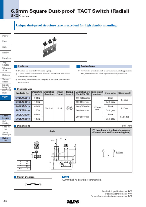
Sharp Feeling Soft Feeling Snap-in Type Surface MountType Radial Type398Power Push Slide Rotary Encoders JogShuttle Telephone -hook Detector Vibration Sensors Dual-in-line Package Type Multi Control Devices TACT6.6mm Square Dust-proof TACT Switch (Radial)SKQK SeriesUnique dust-proof structure type is excellent for high density mounting.Swiches are supplied with radial taping.Allows automatic insertion onto PC board with the radial auto insertion machine.Mounting dimensions are compatible with our conventional SKHV series.FeaturesFor various operations such as various audiovisual apparatuses,TVs, video recorders, and telephones for computerizationApplicationsProducts LineOperating forceTravel mm Rating max. Operating life 5mA 5V DC Initial contactresistance Stem height0.98N 0.98N1.57N 1.57N0.98N0.2550mA12V DC1,000,000cycles 200,000cycles500,000cycles100m max.h=5mmh=7mmh=9.5mmStem colorProducts No.SKQKAAD010SKQKADD010SKQKAED010SKQKAJD010SKQKAKD010SKQKABD010 1.57N Vertical1,000,000cycles 500,000cycles BlackBlackDark gray Dark gray BlackDark grayOperating direction StyleH 6.6øA3.712.7ø412.7180.51859h12hStemDimensionsUnit : mmPC board mounting hole dimensions Viewed from switch mounting face2-ø1 holes5h A 5 3.57 3.39.5312Circuit Diagram1.6mm thick PC board is recommended.NoteFor detailed specifications, see P.413For soldering conditions, see P.414For specifications for the taping package, see P.417Sharp FeelingSoft Feeling Snap-in Type Surface Mount Type Radial Type413PowerPush Slide Rotary Encoders Jog Shuttle Telephone -hook Detector Vibration Sensors Dual-in-line Package Type Multi Control Devices TACTProducts SpecificationsSeriesItemsSharp feeling typeSoft feeling typeOperating temperature range20 to 7050mA 12V DC SKRP : 50mA 16V DC 5mA 12V DCSKPL/PM/PN : 50mA 16V DC30 to 90 SKRA / RG / RP40 to 90 SKPF / PL / PM/ PN30 to 85 SKRM / RW 30 to 80SKPG 10 A 1V DC 100MSKEY/PD : 50M250V AC for 1 min.SKRB/RH/RM/RR/EY/PD : 100V AC for 1min.30 2 for 96h 80 2 for 96h60 2 , 90 to 95%RH for 96h10 to 55 to 10Hz/min., the amplitude is 1.5mm for all the frequencies, in the3 direction of X, Y and Z for 2 hours respectivelyShall be in accordance with individual specifications.Rating max. Rating min.ElectricalperformanceDurabilityEnvironmental performanceInsulation resistanceVoltage proof VibrationLifetime ColdDry heat Damp heatSpecifications of LED SKHJRed Pure green Amber OrangeHigh brightness GreenHigh brightness408015434 5 max.10 max.700 TYP 555 TYP 590 TYP630 TYP 565 TYP100 TYP 20 TYP 30 TYP40 TYP 30 TYP0.4min.1.0TYP 0.4min.1.0TYP 1.5min.4.0TYP 2.0min.5.0TYP0.8min.2.0TYP 2.7max.2.05TYP2.7max.2.0TYP2.7max.2.05TYPColor of lightPower dissipation P mWForward pulse peak current IFP mAForwardcurrent IFDC mA Reverse voltageVR VForward voltageVF VIF=10mAReverse currentIR A VR=4V Peak emission wave lengthpeak nm IF=10mASpectral line half width nm IF=10mALuminous intensity IV mcd IF=10mATACT SwitchesWe can raise the working temperature range for in-vehicle applications upon request. Contact us if you have any requirements of this kind.NoteSharp Feeling Soft Feeling Snap-in Type Surface Mount Type Radial Type414Power Push Slide Rotary Encoders JogShuttle Telephone -hook Detector Vibration Sensors Dual-in-line Package Type Multi Control Devices TACT1. Heating method: Double heating method with infrared heater.2. Temperature measurement: Thermocouple 0.1 to 0.2 CA K or CC T at soldering portion copper foil surface . A heat resisting tapeshould be used for fixed measurement.3. Temperature profileTACT SwitchesSoldering ConditionsCondition for ReflowAvailable for Surface Mount Type. Except SKHM Series200100240˚C max.180˚CTime23 to 4min.Temperature (˚C )20s max.Conditions for Auto-dipAvailable for Snap-in Type and Radial TypeManual SolderingAvailable for Manual Soldering TypeFlux built-up Mounting surface should not be coated with flaxAmbient temperature of the solderedsurface of PC board.100 max.45s max.255 max.5s max.Preheating temperaturePreheating time Soldering temperature Continuous dipping time Items ConditionCondition2times max.Number of solderingSoldering temperature 350 max.3s max.Continuous soldering timeItems1.The condition mentioned above is the temperature on the mounting surface of a PC board. There are cases wherethe P C board's temperature greatly differs from that of the switch, depending on the P C board's material, size,thickness, etc. The above-stated conditions shall also apply to switch surface temperatures. Except a part of Variety SKRM, SKRR Series2.Soldering conditions differ depending on reflow soldering machines. You are requested to verify the soldering conditions thoroughly beforehand.3.Ask us for the specifications of lead-free products.Notes1.Consult with us for TACT switch washing conditions.2.Prevent flux penetration from the top side of the TACT switch.3.Switch terminals and a PC board should not be coated with flux prior to soldering.4.The second soldering should be done after the switch returns to normal temperature.5.Use the flux with a specific gravity of at least 0.83.MH-820V or CF220V by TAMURA Corporation, or their equivalents.NotesSharp FeelingSoft Feeling Snap-in Type Surface Mount Type Radial Type417Power Push Slide Rotary Encoders Jog Shuttle Telephone -hookDetector Vibration Sensors Dual-in-line Package Type Multi Control DevicesTACTSpecification of Radial Taping PackageTaping Packaging for Auto-insertionThe SKHV, SKQC,SKQK, SKQN, SKQW, SKRC, SKRG, SKRS, SKPD and SKPL series are delivered with taping packaging.Box SizeABCUnit : mmSeriesSKHV SKQC SKQK SKRS SKPD SKQN 47331291SKRGAL to AS SKRGAA to AFSKPL SKRC48SKQW613342353404355337370A B CSeriesSKHV SKQKSKQW SKRS SKQCSKPD SKRG1,0007001,5008002,000SKQN SKRC SKPL9002,700Qty / reel pcs. Minimum packing unitQuantity Accommodated Per BoxTACT Switches。
abb 安全锁 GKey 产品手册说明书

—安全产品安全锁GKey产品手册阅读和理解本文档使用产品前,请阅读和理解本文档。
如果您有任何问题或意见,请咨询 ABB Jokab Safety 代表。
适用性ABB Jokab Safety 对于客户应用中的产品组合或产品使用是否符合相应的任何标准、法令或法规不负责任。
产品的第三方认证文件可在https:///low-voltage/products/safety-products上获得。
仅凭此信息不足以完全确定产品是否适用或是否适合与最终产品、机器、系统或其他应用一起使用。
以下是一些必须特别注意的应用示例。
这不是产品的所有可能用途的完整列表,也不表示列出的用途可能适合产品:•室外使用、涉及可能的化学污染或电气干扰的使用,或者本文档中未介绍的情况或用途。
•核能控制系统、燃烧系统、铁路系统、航空系统、医疗设备、娱乐游戏机、车辆以及受单独的行业或政府法规约束的系统。
•危及生命财产安全的系统、机器和设备。
请了解并遵守产品的所有使用禁忌。
对于严重危及生命财产安全且无法确保整个系统的设计可排除该风险以及 ABB JOKAB SAFETY 产品具有正确的额定值并正确安装在整个设备或系统内按预定用途使用的应用,切勿使用该产品。
目录1简介 (4)范围 (4)目标读者 (4)阅读前提.................................................................................... Error! Bookmark not defined.特殊事项 (4)2概述 (5)一般说明 (5)安全信息 (5)3安装 (6)安装注意事项 (6)安装 (6)3.2.1机械安装 (6)3.2.2安装后检查 (6)3.2.3安装参考范例 (7)4电气接头 (8)5功能 (9)一般功能 (9)RFID 编码 (9)逃生释放 (9)手动解锁功能(辅助解锁) (9)闭锁功能 (10)LED诊断 (10)复位说明– RFID 执行机构 (11)5.7.1使用内部复位按钮复位 (11)5.7.2使用外部复位输入进行复位(终端“ER”) (11)6维护 (12)7模型概述 (13)GKey系列 (13)按钮指示装置 (13)尺寸 (14)8技术参数 (15)9EC 符合标准声明 (17)1简介范围该原始说明旨在介绍GKey安全锁并提供安装和使用所需的必要信息。
欧姆龙轻触式开关使用注意事项 说明书

欧姆龙轻触式开关使用注意事项安全要点请在额定负载范围内进行使用。
若超过额定负载范围的使用,不仅会影响开关的耐久性,还可能引起发热、烧损等危险情况。
因此开关时包括瞬时电压、电流都应在额定电压、额定电流的范围内进行使用。
使用注意事项关于保存1. 保存环境· 保存产品时,为了防止端子部变色,请不要在下列条件下保存。
①高温、高湿环境下②有腐蚀性气体的环境中③阳光直射的场所2. 保存状态· 请在保留包装的状态下进行保存。
包装开封后,请尽快进行使用,并且将剩余部件在防湿、无腐蚀气体的环境中进行适当保存。
关于使用1. 操作方法不可施加强力反复操作。
在柱塞已经按下的情况下进一步加压的话,过大的负荷重量可能导致圆形板弹簧的变形,成为动作不良的原因。
特别是对横压型施加过大负载的话,铆接部会产生破损,成为开关破损的原因。
因此在安装、操作时等,请注意不要附加高于过大负荷重量(29.4N、1分钟、1次)的负荷重量。
请按柱塞可以在垂直方向动作的方向设定开关。
只按柱塞的一侧,或斜向的操作口可能导致耐久性降低2. 尘埃对策因为是没有密封构造的开关,因此请勿在有粉尘的场所进行使用。
不得不使用的情况下,应该考虑采用覆盖物等保护对策。
3. 使用环境的调查· 实际使用状态下进行设置时,请先确认其周围的设备是否会有产生腐蚀性气体的情况发生。
避免在高温、高湿、具有腐蚀性气体硫化物(H2S、SO2)、氨(NH3)、硝酸(NHO3)、氯(Cl2)等)的环境中使用。
接点接触不良、腐蚀等可能导致故障产生,使用时请注意。
接点接触不良、腐蚀等可能导致故障产生,使用时请注意。
· 使用环境中存在有硅时,可能导致接触不良的情况发生。
开关的周围存在有硅制品(硅油、硅填充材料、硅电线等)时,请通过接点保护回路进行电弧抑制或除去硅发生源等措施。
下述事项可能导致开关内部浸水、接点接触不良、腐蚀等情况的发生,导致设备故障的产生。
安全压力开关说明书

221 Code Process R ange & Temp.(6) Vac 0-600 1000 2000- Material Limits in.H 2O psi psi 3000 °F psi B-Buna N 0 to 150 ● ● ● ● V-Viton 20 to 300 ● ● ● T-Teflon 0 to 150 ● ● ● ● S-SS (5)(10) 0 to 300 ● ● P -Monel (5)(10) 0 to 300 ● ● NOTES: 1. Standard switch. 2. D ual switches are 2 SPDT snap-action switches not independently adjustable. 3. Estimated dc rating, 2.5A, 28 Vdc (not UL listed). 4. Estimated dc rating, .4A, 120 Vdc (not UL listed). 5. Available on pressure only. 6. A mbient operating temperature limits –20 to 150°F , all styles. Setpoint shift of ±1% of range per 50°F is normal. Switch calibrated at 70°F reference. 7. Items are wetted by process fluid. 8. Refer to Option Table. 9. O rder Option XUD, stainless steel process connection.10. On differential switches, stainless steel is available in 15, 30, 60 and 90 psid ranges only. Includes Teflon O-ring and 316 SS connection. TO ORDER THIS B-SERIES PRESSURE SWITCH:Pressure and Differential Pressure Switches, Watertight Enclosure, Type 400, B-Series • C hoice of actuators, including designs for fire-safe and NACE applications (8)• Readily available • Standard pressure connection materials: Pressure psi ranges - 316L stainless steel Differential psid ranges- Nickel-plated brass (9) of water ranges - Epoxy coated carbon steel B4 - P ressure switch, type 400, watertightenclosure meets NEMA 3, 4, 4X and 13, IP66 requirementsD4 - D ifferential pressure switch, type 400,watertight enclosure meets NEMA 3, 4, 4X and 13, IP66 requirementsThis general purpose Ashcroft ® switch series is ideal for use in virtually all Industrial and OEM applications.• Watertight NEMA 4X enclosure, IP66• Choice of switch elements for all applications, including hermeti-cally sealed• Wide choice of wetted materials, including all-welded Monel or stainless steel• Fixed or limited adjustable deadband• Approved for UL, CSA and FM (8) ratings • Setpoints adjustable from 15-100% of range4 - OPTIONS (See pages 238-239)5 - STANDARD PRESSURE RANGES (See page 235) 3 - ACTUATOR SEAL (7) Order D escription/Maximum Electrical Ratings Code UL/CSA Listed SPDT 20(4) Narrow deadband 15A, 125/250 Vac 21(9) Ammonia service 5A, 125/250 VacHermetically sealed22(3) switch, narrow 5A, 125/250 Vac deadband 23 Heavy duty ac 20A,125/250 Vac15A,125/250/480 Vac 24(1)General purpose 1/2A, 125 Vdc 1/4A, 250 Vdc 25 Heavy duty dc 10A,125/ Vac or dc 1/8HP 125/ Vac or dc 26(4)Sealed environment 15A, 125/250 Vac proof 27 High temp. 300°F 15A, 125/250 Vac 28Manual reset trip 15A, 125/250 Vac on increasing 29 Manual reset trip 15A, 125/250 Vac on decreasing 31 Low level (gold) 1A,125/250 Vac contactsHermetically sealed32 switch, general 11A, 125/250 Vac purpose 5A, 30 Vdc50 Variable deadband 15A,125/250 Vac UL/CSA Listed Dual SPDT (2)We recommend hermetically sealed switch elements for improved reliability. The hermetically sealed switch provides uncompromising contact protection in harsh or corrosive environments. The Ashcroft 400 Series is also approved for installation in Division II hazardous areas when supplied with hermetically sealed contacts.L-recognized component, LOOK FOR THIS AGENCY MARK ON OUR PRODUCTS。
通用智能开关使用说明书
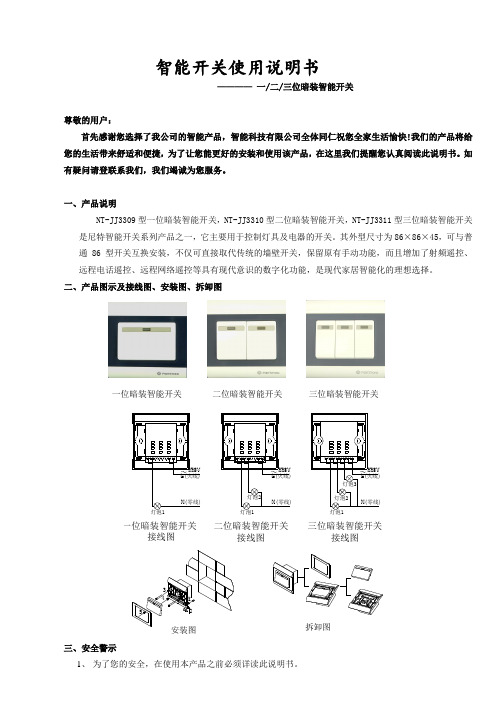
智能开关使用说明书————一/二/三位暗装智能开关尊敬的用户:首先感谢您选择了我公司的智能产品,智能科技有限公司全体同仁祝您全家生活愉快!我们的产品将给您的生活带来舒适和便捷,为了让您能更好的安装和使用该产品,在这里我们提醒您认真阅读此说明书。
如有疑问请登联系我们,我们竭诚为您服务。
一、产品说明NT-JJ3309型一位暗装智能开关,NT-JJ3310型二位暗装智能开关,NT-JJ3311型三位暗装智能开关是尼特智能开关系列产品之一,它主要用于控制灯具及电器的开关。
其外型尺寸为86×86×45,可与普通86型开关互换安装,不仅可直接取代传统的墙壁开关,保留原有手动功能,而且增加了射频遥控、远程电话遥控、远程网络遥控等具有现代意识的数字化功能,是现代家居智能化的理想选择。
二、产品图示及接线图、安装图、拆卸图一位暗装智能开关二位暗装智能开关三位暗装智能开关220VN(零线)L(火线)220V灯泡1灯泡2灯泡3N(零线)L(火线)220V一位暗装智能开关接线图灯泡2灯泡1N(零线)L(火线)三位暗装智能开关接线图二位暗装智能开关接线图灯泡1安装图345213拆卸图三、安全警示1、为了您的安全,在使用本产品之前必须详读此说明书。
2、聘请专业电工为您安装或拆卸开关,安装或拆卸开关时,必须先切断电源。
3、本开关安装在洗漱间、浴室等潮湿的地方时应装防溅盒或采取防潮措施。
4、配接负载时应严格控制在负载功率之内。
5、安装开关时严禁锤打、过力紧固以防面板变形,同时严禁金属物掉入开关外壳内。
四、概念解释:1、学习状态:此时可以把遥控器的某一指令代码,存储于开关(插座、单路控制器)的记忆芯片中,从而实现两者之间的相互确认2、对码:实现遥控器和开关(插座、单路控制器)的相互确认。
如果不进行对码,遥控器则不能控制该开关(插座、单路控制器)3、数字对码:实现遥控器数字键和开关(插座、单路控制器)的相互确认。
安全开关产品说明书
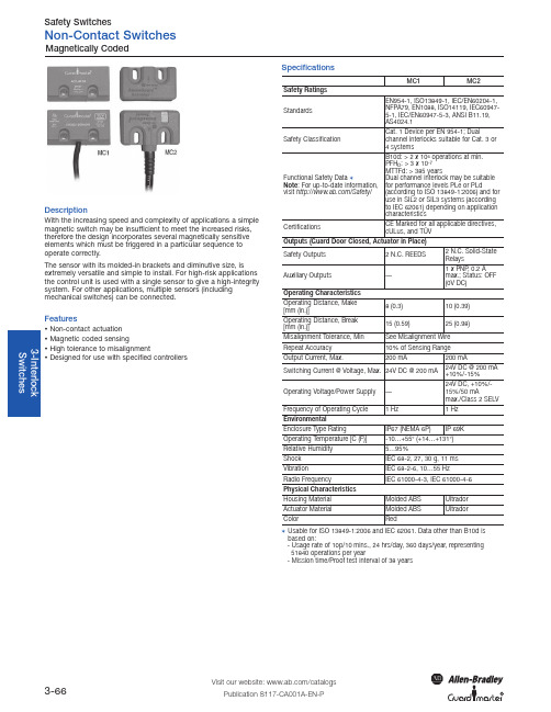
Visit our website: /catalogsPublication S117-CA001A-EN-P3-66DescriptionWith the increasing speed and complexity of applications a simple magnetic switch may be insufficient to meet the increased risks,therefore the design incorporates several magnetically sensitive elements which must be triggered in a particular sequence to operate correctly.The sensor with its molded-in brackets and diminutive size, is extremely versatile and simple to install. For high-risk applications the control unit is used with a single sensor to give a high-integrity system. For other applications, multiple sensors (including mechanical switches) can be connected.FeaturesNon-contact actuation Magnetic coded sensingHigh tolerance to misalignmentDesigned for use with specified controllersSpecificationsMC1MC2Safety Ratings StandardsEN954-1, ISO13849-1, IEC/EN60204-1,NFPA79, EN1088, ISO14119, IEC60947-5-1, IEC/EN60947-5-3, ANSI B11.19,AS4024.1Safety ClassificationCat. 1 Device per EN 954-1; Dualchannel interlocks suitable for Cat. 3 or 4 systemsFunctional Safety Data 1Note : For up-to-date information,visit /Safety/B10d: > 2 x 10⁶operations at min.PFH D : > 3 x 10⁻⁷MTTFd: > 385 yearsDual channel interlock may be suitable for performance levels PLe or PLd(according to ISO 13849-1:2006) and for use in SIL2 or SIL3 systems (according to IEC 62061) depending on application characteristicsCertificationsCE Marked for all applicable directives,cULus, and TÜVOutputs (Guard Door Closed, Actuator in Place)Safety Outputs 2 N.C. REEDS 2 N.C. Solid-State RelaysAuxiliary Outputs—1 x PNP , 0.2 A max.; Status: OFF (0V DC)Operating Characteristics Operating Distance, Make [mm (in.)]8 (0.3)10 (0.39)Operating Distance, Break [mm (in.)]15 (0.59)25 (0.98)Misalignment Tolerance, Min See Misalignment Wire Repeat Accuracy 10% of Sensing Range Output Current, Max.200 mA200 mASwitching Current @ Voltage, Max.24V DC @ 200 mA 24V DC @ 200 mA +10%/-15%Operating Voltage/Power Supply —24V DC, +10%/-15%/50 mAmax./Class 2 SELV Frequency of Operating Cycle 1 Hz1 Hz Environmental Enclosure Type Rating IP67 (NEMA 6P)IP 69KOperating Temperature [C (F)]-10…+55° (+14…+131°)Relative Humidity 5…95%Shock IEC 68-2, 27, 30 g, 11 ms Vibration IEC 68-2-6, 10…55 Hz Radio Frequency IEC 61000-4-3, IEC 61000-4-6Physical Characteristics Housing Material Molded ABS Ultrador Actuator Material Molded ABS UltradorColorRed1Usable for ISO 13849-1:2006 and IEC 62061. Data other than B10d isbased on:- Usage rate of 1op/10 mins., 24 hrs/day, 360 days/year, representing 51840 operations per year- Mission time/Proof test interval of 38 years3-67Visit our website: /catalogsPublication S117-CA001A-EN-P3-I n t e r l o c k S w i t c h e sProduct SelectionReplace symbol with 1 (1 m), 2 (2 m), 3 (3 m), 5 (5 m), or 10 (10 m) for standard cable lengths.‡Replace symbol with 4 or 8 for number of ports.Note : For additional information, see the page 7-1.Note : For additional Safety Relays connectivity, see page 5-12.For additional Safety I/O and Safety PLC connectivity, see page 5-116.For application and wiring diagrams, see page 10-1.3-68Visit our website: /catalogsPublication S117-CA001A-EN-P12MC1MC2Approximate DimensionsDimensions are shown in mm (in.). Dimensions are not intended to be used for installation purposes.3-69Visit our website: /catalogsPublication S117-CA001A-EN-P3-I n t e r l o c k S w i t c h e sSensing & Misalignment CurveActuatorM a k e -B r e akM a k e -B r e a kMC1MC2MC2 Application Wiring ExampleMagnetically Coded Small Flat Pack+24v0vS a f e t y A +S a f e t y A -S a f e t y B +S a f e t y B -A u xN /A3313A1S11S1223S3414A2S21S2224MSR127RP+24V0V1425S 34MK1K1K2L1B r o w n (2)B l u e (7)R e d (8)G r e y (5)Y e l l o w (4)P i n k (6)G r e e n (3)W h i t e (1)R e dG r e yP i n kY e l l o wL2L342K2。
EUCHNER安士能安全锁安全开关中文说明书

ZH使用说明书安全系统MGB-L0…-AR.-…MGB-L0…-AP.-…V3.0.0以上使用说明书 安全系统MGB-L0…-AR.-…和MGB-L0…-AP.-…内容1. 关于本文件 (4)1.1. 适用性 (4)1.1.1. 关于旧产品版本的提示 (4)1.2. 目标群体 (4)1.3. 符号说明 (4)1.4. 补充文件 (5)2. 正确的使用方法 (6)2.1. MGB-AP和MGB-AR的主要区别 (7)3. 安全功能说明 (8)4. 免责和质保 (9)5. 一般安全提示 (9)6. 功能 (10)7. 系统概览 (11)7.1. 锁闭模块MGB-L0-... .. (11)7.2. 手柄模块MGB-H-... . (11)7.3. MGB-E-...紧急逃生解锁装置(选配) . (11)7.4. 外形尺寸图 (12)7.5. 防关闭插件 (13)7.6. 紧急逃生解锁装置(选配) (14)7.6.1. 准备紧急逃生解锁装置 (14)8. 安装 (16)8.1. 安装颜色光片 (17)9. 调整触发方向(此处:从右向左) (19)10. 防止受环境影响 (20)11. 电气连接 (21)11.1. 关于的说明 (22)11.2. 发生故障时的安全功能保障 (22)11.3. 电源保险装置 (22)11.4. 对连接电缆的要求 (23)11.5. 电缆布设提示 (23)11.6. 更改设备配置(使用DIP开关) (24)11.6.1. 更改系统家族(AR/AP转换) (24)11.7. 在控制系统上运行的提示 (25)11.8. 接线布局和触点说明 (26)11.9. 作为单个设备运行 (27)11.10. 在AR开关链中运行 (28)2(原版使用说明书译文) 112657-12-01/153112657-12-01/15 (原版使用说明书译文)使用说明书 安全系统MGB-L0…-AR.-…和MGB-L0…-AP.-…ZH11.11. 在AR开关链中的运行提示 (29)11.11.1. 系统时间 ............................................................................................................................................2911.11.2. AR开关链的布线 ...............................................................................................................................2911.11.3. 开关链中设备的数量 .......................................................................................................................2911.11.4. 开关链复位 . (29)12. 调试 (30)12.1. 初始化过程(仅适用于特殊编码的MGB) .....................................................................................................3012.2. 机械功能测试 ......................................................................................................................................................3012.3.电气功能测试 (31)13. 技术参数 (32)13.1.典型系统时间 (33)14.系统状态 (33)14.1. 符号说明 ...............................................................................................................................................................3314.2. MGB-AR系统状态表 .............................................................................................................................................3414.3.MGB-AP系统状态表 (35)15. 故障排除和帮助 (36)15.1. 故障复位 ...............................................................................................................................................................3615.2. 互联网上的故障排除帮助 ..................................................................................................................................3615.3. 互联网上的安装帮助 ..........................................................................................................................................3615.4.应用示例 (36)16. 服务 ..............................................................................................................................................3617. 检查和维护 ..................................................................................................................................3718.符合标准声明 (38)使用说明书 安全系统MGB-L0…-AR.-…和MGB-L0…-AP.-…1. 关于本文件1.1. 适用性本使用说明书适用于全部MGB-L0…-AR.-…和MGB-L0…-AP.-…。
安全限位开关说明书
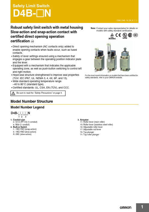
Robust safety limit switch with metal housing Slow-action and snap-action contact with certified direct opening operation•Direct opening mechanism (NC contacts only) added to enable opening contacts when faults occur, such as fused contacts.•Safety of lever settings ensured using a mechanism thatengages a gear between the operating position indicator plate and the lever.•Equipped with a mechanism that indicates the applicableoperating zone, as well as push-button switching to control left and right motion.•Head seal structure strengthened to improve seal properties(TÜV: IEC IP67, UL: NEMA 3, 4, 4X, 6P, and 13).•Wide standard operating temperature range: –40 to 80°C (standard type).•Certified standards: UL, CSA, EN (TÜV), and CCC.Model Number StructureModel Number Legend 1.Conduit size2:G1/2 (PF1/2) (1-conduit)4:M20 (1 conduit)2.Built-in Switch1:1NC/1NO (snap-action)5:1NC/1NO (slow-action) A:2NC (slow-action)3.Actuator11:Roller lever (resin roller)15:Roller lever (stainless steel roller)16:Adjustable roller lever 17:Adjustable rod lever 70:Top plunger71:Top roller plungerFor the most recent information on models that have been certified for safety standards, refer to your OMRON website.Be sure to read the “Safety Precautions” on page 9.Ordering InformationSet Model NumbersConsult with your OMRON representative when ordering any models that are not listed in this table. Safety Limit Switches (with Direct Opening Mechanism)General-purpose Limit SwitchesNote:Consult your OMRON representative for products.SpecificationsStandards and EC DirectivesConforms to the following EC Directives:•Machinery Directive •Low Voltage Directive •EN50041•EN60204-1•EN1088Certified StandardsSnap-action ModelsSlow-action ModelsCertified Standard RatingsTÜV (EN60947-5-1), CCC (GB14048.5)Note:As protection against short-circuiting, use either a gI -type or gG -type 10 A fuse that conforms to IEC60269.UL/CSA: (UL508, CSA C22.2 No. 14)A600ItemUtilization category AC-15Rated operating current (I e ) 2 A Rated operating voltage (U e )400 VRated voltage Carry currentCurrent (A)Volt-amperes (VA)MakeBreakMakeBreak120 VAC 240 VAC 480 VAC 600 VAC10 A 60 30 15 126 3 1.5 1.27,200 720RatingsNote:1.The above values are continuous currents.2.Inductive loads have a power factor of 0.4 or higher (AC) or a time constant of 7 ms or lower (DC).mp loads have a inrush current of 10 times the normal current.4.Motor loads have a inrush current of 6 times the normal current.CharacteristicsNote:1.The above values are initial values.2.The above values may vary depending on the model. Consult your OMRON sales representative for details.*1.The degree of protection is tested using the method specified by the standard (EN60947-5-1). Confirm that sealing properties are sufficient forthe operating conditions and environment beforehand.*2.The durability is for an ambient temperature of 5 to 35°C and ambient humidity of 40% to 70%. For further conditions, consult your OMRONsales representative.*3.The above values may vary depending on switching frequency, environmental condition, and relativity level, consult your OMRON salesrepresentative.Rated voltage (V)Non-inductive load (A)Inductive load (A)Resistive load Lamp loadInductive loadMotor loadNCNONCNONCNONCNO125 VAC 250400101010321.5 1.510.810103531.5 2.51.50.88 VDC 1430125250101060.80.46640.20.13330.20.1101060.80.46640.20.1Inrush current30 A max.Degree of protection *1IP67 (EN60947-5-1)Durability *2Mechanical 30,000,000 operations min. (snap-action)10,000,000 operations min. (slow-action)Electrical500,000 operations min. (10 A resistive load at 250 VAC)Operating speed 1 mm/s to 0.5 m/s Operating frequency Mechanical 120 operations/minute Electrical 30 operations/minute Contact resistance25 m Ω max.Minimum applicable load *3General load 180 mA resistive load at 5 VAC Gold-clad contact 20 mA resistive load at 5 VAC (N-level reference value)Rated insulation voltage (U i )600 V (EN60947-5-1)Rated frequency50/60 HzProtection against electric shock Class I (with ground terminal)Pollution degree (operating environment)3 (EN60947-5-1)Impulse withstand voltage (EN60947-5-1)Between terminals of same polarity2.5 kV (snap-action)/4 kV (slow-action)Between terminals of different polarity4 kV (slow-action)Between eachterminal and ground4 kVInsulation resistance 100 M Ω min. (at 500 VDC) between terminals of the same polarity and between each terminal and non-current-carrying part Contact gap 2 × 2 mm min. (slow-action)2 × 0.5 mm min. (snap-action)Vibration resistance Malfunction 10 to 55 Hz, 0.75 mm single amplitude Shock resistanceDestruction 1,000 m/s 2 min.Malfunction300 m/s 2 min.Conditional short-circuit current100 A (EN60947-5-1)Conventional enclosed thermal current (I the )20 A (EN60947-5-1)Ambient operating temperature –40 to 80°C (with no icing) Ambient operating humidity 95% max.WeightApprox. 250 gEngineering DataElectrical Durability (Snap-action)(Ambient temperature: 5 to 30°C, ambient humidity: 40 to 70%)Structure and NomenclatureStructure250 V AC 125 V AC1,0001,000500500300300100100505030301010480 V AC 250 V AC500 V AC(cos φ = 1)(cos φ = 0.4)O p e r a t i o n s (x 104)O p e r a t i o n s (x 104)S w itching c u rrent (A)S w itching c u rrent (A)Operating fre qu encies: 30 times/min., cos φ = 1Operating fre qu encies: 30 times/min., cos φ = 0.4selection of operation on only oneDirect Opening Mechanism1NO/1NC Contact (Snap-action)1NC/1NO Contact (Slow-action)2NC Contact (Slow-action)Contact FormNote:Terminal numbers are according to EN50013; contact symbols are according to IEC60947-5-1.AMo v a b le contactPl Safety camFixed contact (N C)le contact Safety cam directly p mo b lled apart.Dimensions and Operating Characteristics(Unit: mm)Note:Omitted dimensions are the same as those for the Roller Lever Type ModelsD4B-2@@@N have a G1/2 conduit opening. D4B-4@@@N have a M20 conduit opening.SwitchesNote:Unless otherwise specified, a tolerance of 0.4 mm applies to all dimensions.*1.The lever can be set to any desired position by turning the operating position indicator.*2.In terms of construction, the Switch is a General-purpose Limit Switch rather than a Safety Limit Switch.Note:Variation occurs in the simultaneity of contact opening/closing operations of 2NC contacts. Check contact operation.*1.The operating characteristics of these Switches were measured with the roller level set at 31.5 mm.*2.The operating characteristics of these Switches were measured with the rod level set at 140 mm.*3.Only for slow-action models.*4.Only for snap-action models.*5.Reference values.*6.Must be provided to ensure safe operation.Model Operating characteristics D4B-@@11N D4B-@@15N D4B-@@16N *1D4B-@@17N*2Operating force Release force PretravelOvertravelMovement differential Direct opening travel Direct opening force Total travelOF max.RF min.PTPT (2nd) *3 *5OT min.MD max. *4DOT min. *3 *6*4 *6DOF min. *6TT *59.41N1.47N 21°±3°(45°)50°12°35°55°19.61N (75°)9.41N 1.47N 21°±3°(45°)50°12°35°55°19.61N (75°)9.41N 1.47N 21°±3°(45°)50°12°35°55°19.61N (75°)2.12N 0.29N 21°±3°(45°)50°12°35°55°19.61N (75°)131.325 to Adjustable Roller Lever D4B-@@16NAdjustable Rod Lever D4B-@@17NNote:Unless otherwise specified, a tolerance of ±0.4 mm applies to all dimensions. Operating characteristics Model D4B-@@70N D4B-@@71NOperating force Release force PretravelOvertravel Movement differential Direct opening travel Direct opening force Total travel OF max.RF min.PT max.PT (2nd) *1 *3OT min.MD max. *2DOT min. *4DOF min. *4TT *318.63 N1.96 N2 mm(3 mm)5 mm1 mm3.2 mm49.03 N(7 mm)18.63 N1.96 N2 mm(3 mm)5 mm1 mm3.2 mm49.03N(7 mm)Note:Variation occurs in the simultaneity ofcontact opening/closing operations of2NC contacts. Check contactoperation.*1.Only for slow-action models.*2.Only for snap-action models.*3.Reference values.*4.Must be provided to ensure safeoperation.Free position Operating position FP max.OP38 mm35±1 mm51 mm48±1 mmApplication PrecautionSafety PrecautionsBe sure to read the precautions for All Safety Limit Switches in the website at:/.Indication and Meaning for Safe Use•Do not use the Switch submerged in oil or water, or in locations continuously subject to splashes of oil or water. Doing so may result in oil or water entering the Switch interior. (The IP67 degree of protection specification for the Switch refers to water penetration while the Switch is submersed in water for a specified period of time.)•Always attach the cover after completing wiring and before using the Switch. Also, do not turn ON the Switch with the cover open.Doing so may result in electric shock.MountingUse four M5 screws with washers to mount the standard model. Be sure to apply the proper torque to tighten each screw. Mounting Dimensions (M5)•To change the angle of the lever, loosen the Allen-head bolts on the side of the lever.•The operating position indicator plate * has protruding parts which engage with the lever, thus allowing changes to the lever position by 90°.•The back of the operating position indicator plate * has noprotruding parts. If this plate is turned over and attached, any angle within a 360° range can be set. Do not turn over the plate, however, when using the D4B-@N as a switch with a certified direct opening mechanism. For an SUVA- or BIA-certified application, make sure that the lever engages with the operating position indicator plate securely so that the lever will not slip.*The operating position indicator plate: Refer to page 5. Changes in Head Mounting PositionBy removing the screws on the four corners of the head, the head can be reset in any of four directions. Make sure that no foreign materials will penetrate through the head.Changing the Operating Direction Switches with Roller LeversThe operating direction of the lever can be easily changed without using any tools. It can be set toclockwise operation (CW) or counterclockwise (CCW) operation.Use the procedure given at the right to change the operating direction.Head Co OperatingPrecautions for Safe Use Supplementary comments on what to do or avoid doing, to use the product safely.Precautions for Correct Use Supplementary comments on what to do or avoid doing, to prevent failure to operate, or undesirable effect on product performance.Precautions for Safe Use Precautions for Correct UseD4B-@NWiringDo not connect the bare lead wires directly to the terminals but be sure to connect each of them by using an insulation tube and M3.5 round crimp terminals and tighten each terminal screw within the specified torque range.The proper lead wire is 20 to 14 AWG (0.5 to 2.5 mm 2) in size.Make sure that all crimp terminals come into contact with the casing or cover as shown below, otherwise the cover may not be mounted properly or the D4B-@N may malfunction.Conduit Opening•Make sure that each connector is tightened within the specifiedtorque range.The casing may be damaged if the connector is tightened excessively.•Use an OMRON SC-series Connector (sold separately) that is suited to the cable in diameter.Others•The load for the actuator (roller) of the Switch must be imposed on the actuator in the horizontal direction, otherwise the actuator or•@@17N, theSwitch may telegraph. To avoid telegraphing, take the following precautions.1.Set the lever to operate in one direction.2.Modify the rear end of the dog to an angle of 15° to 30° as3.signals.D dia.dz dia.CasingCo v erT erminal scre wCrimp terminalT erminal scre wCasingT erminal scre wCo v erCrimp terminalCorrectCorrectIncorrectIncorrectCrimp terminalCrimp terminalCrimp terminalCorrectIncorrectRead and Understand This CatalogPlease read and understand this catalog before purchasing the products. Please consult your OMRON representative if you have any questions orcomments.WARRANTYOMRON's exclusive warranty is that the products are free from defects in materials and workmanship for a period of one year (or other period if specified) from date of sale by OMRON.OMRON MAKES NO WARRANTY OR REPRESENTATION, EXPRESS OR IMPLIED, REGARDING NON-INFRINGEMENT, MERCHANTABILITY, OR FITNESS FOR PARTICULAR PURPOSE OF THE PRODUCTS. ANY BUYER OR USER ACKNOWLEDGES THAT THE BUYER OR USER ALONE HAS DETERMINED THAT THE PRODUCTS WILL SUITABLY MEET THE REQUIREMENTS OF THEIR INTENDED USE. OMRON DISCLAIMS ALL OTHER WARRANTIES, EXPRESS OR IMPLIED.LIMITATIONS OF LIABILITYOMRON SHALL NOT BE RESPONSIBLE FOR SPECIAL, INDIRECT, OR CONSEQUENTIAL DAMAGES, LOSS OF PROFITS OR COMMERCIAL LOSS IN ANY WAY CONNECTED WITH THE PRODUCTS, WHETHER SUCH CLAIM IS BASED ON CONTRACT, WARRANTY, NEGLIGENCE, OR STRICT LIABILITY.In no event shall the responsibility of OMRON for any act exceed the individual price of the product on which liability is asserted.IN NO EVENT SHALL OMRON BE RESPONSIBLE FOR WARRANTY, REPAIR, OR OTHER CLAIMS REGARDING THE PRODUCTS UNLESSOMRON'S ANALYSIS CONFIRMS THAT THE PRODUCTS WERE PROPERLY HANDLED, STORED, INSTALLED, AND MAINTAINED AND NOTSUBJECT TO CONTAMINATION, ABUSE, MISUSE, OR INAPPROPRIATE MODIFICATION OR REPAIR.SUITABILITY FOR USEOMRON shall not be responsible for conformity with any standards, codes, or regulations that apply to the combination of products in the customer's application or use of the products.At the customer's request, OMRON will provide applicable third party certification documents identifying ratings and limitations of use that apply to the products. This information by itself is not sufficient for a complete determination of the suitability of the products in combination with the end product, machine, system, or other application or use.The following are some examples of applications for which particular attention must be given. This is not intended to be an exhaustive list of all possible uses of the products, nor is it intended to imply that the uses listed may be suitable for the products:∙Outdoor use, uses involving potential chemical contamination or electrical interference, or conditions or uses not described in this catalog.∙Nuclear energy control systems, combustion systems, railroad systems, aviation systems, medical equipment, amusement machines, vehicles, safety equipment, and installations subject to separate industry or government regulations.∙Systems, machines, and equipment that could present a risk to life or property.Please know and observe all prohibitions of use applicable to the products.NEVER USE THE PRODUCTS FOR AN APPLICATION INVOLVING SERIOUS RISK TO LIFE OR PROPERTY WITHOUT ENSURING THAT THE SYSTEM AS A WHOLE HAS BEEN DESIGNED TO ADDRESS THE RISKS, AND THAT THE OMRON PRODUCTS ARE PROPERLY RATED AND INSTALLED FOR THE INTENDED USE WITHIN THE OVERALL EQUIPMENT OR SYSTEM.PROGRAMMABLE PRODUCTSOMRON shall not be responsible for the user's programming of a programmable product, or any consequence thereof.CHANGE IN SPECIFICATIONSProduct specifications and accessories may be changed at any time based on improvements and other reasons.It is our practice to change model numbers when published ratings or features are changed, or when significant construction changes are made.However, some specifications of the products may be changed without any notice. When in doubt, special model numbers may be assigned to fix or establish key specifications for your application on your request. Please consult with your OMRON representative at any time to confirm actualspecifications of purchased products.DIMENSIONS AND WEIGHTSDimensions and weights are nominal and are not to be used for manufacturing purposes, even when tolerances are shown.PERFORMANCE DATAPerformance data given in this catalog is provided as a guide for the user in determining suitability and does not constitute a warranty. It may represent the result of OMRON’s test conditions, and the users must correlate it to actual application requirements. Actual performance is subject to the OMRON Warranty and Limitations of Liability.ERRORS AND OMISSIONSThe information in this document has been carefully checked and is believed to be accurate; however, no responsibility is assumed for clerical,typographical, or proofreading errors, or omissions.2012.10In the interest of product improvement, specifications are subject to change without notice. OMRON CorporationIndustrial Automation Company/(c)Copyright OMRON Corporation 2012 All Right Reserved.。
KLM、KLP和KL3-SS系列的保护锁定安全开关说明书
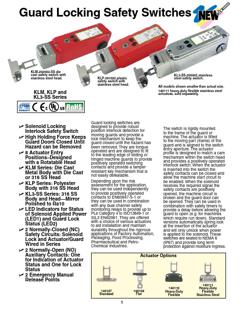
Guard Locking Safety Switches KLM, KLP andU S olenoid LockingInterlock Safety SwitchU H igh Holding Force Keeps Guard Doors Closed UntilHazard can be RemovedU8 Actuator EntryPositions–Designedwith a Rotatable HeadU K LM Series: Die CastMetal Body with Die Castor 316 SS HeadU K LP Series: PolyesterBody with 316 SS HeadU K L3-SS Series: 316 SS Body and Head—MirrorPolished to Ra10U L ED Indicators for Status of Solenoid Applied Power (LED1) and Guard LockStatus (LED2)U2 Normally-Closed (NC) Safety Circuits: SolenoidLock and Actuator/GuardWired in SeriesU2 Normally-Open (NO) Auxiliary Contacts: Onefor Indication of ActuatorStatus and One for LockStatusU 2 Emergency ManualRelease Points Guard locking switches aredesigned to provide robustposition interlock detection formoving guards and provide alock mechanism to keep theguard closed until the hazard hasbeen removed. They are tongueoperated and are designed to fitto the leading edge of sliding orhinged machine guards to providepositively operated switchingcontacts and provide a tamperresistant key mechanism that isnot easily defeatable.Depending upon the riskassessment for the application,they can be used independentlyto provide positively operatedcontacts to EN60947-5-1 orthey can be used in combinationwith any dual channel safetymonitoring relays to provide up toPLe Category 4 to ISO13849-1 orSIL3 EN62061. They are offeredwith a choice of various actuatorsto aid installation and maintaindurability throughout the rigorousapplications of Factory Automation,Packaging, Food Processing,Pharmaceutical and Petro-Chemical Industries.The switch is rigidly mountedto the frame of the guard ormachine. The actuator is fittedto the moving part (frame) of theguard and is aligned to the switchentry aperture. The actuatorprofile is designed to match a cammechanism within the switch headand provides a positively operatedinterlock switch. When the actuatoris inserted into the switch thesafety contacts can be closed andallow the machine start circuit tobe enabled. When the solenoidreceives the required signal thesafety contacts are positivelyopened, the machine circuit isbroken and the guard door canbe opened. They can be used incombination with safety timers toprovide a delay before allowing theguard to open (e.g. for machineswhich require run down). Standardversions automatically spring lockat the insertion of the actuatorand will only unlock when poweris applied to the solenoid. Theseswitches are sealed to NEMA 6(IP67) and provide long termprotection against moisture ingress.140108140111All models shown smaller than actual size.140111 heavy-duty flexible stainless steelactuators, sold separately.KLM-202002-SS diecast safety switch withstainless steel head.KLP-201002 plasticsafety switch withstainless steel head.KL3-SS-205002 stainless steel safety switch.Standards: ISO14119, EN60947-5-1, EN60204-1, ISO13849-1, EN62061 UL508Safety Classification and Reliability Data:Mechanical Reliability B10d: 2.5 x 10⁶ operations at 100 mA loadISO13849-1: Up to PLe depending upon system architectureEN62061: Up to SIL3 depending upon system architectureSafety Data–Annual Usage: 8 cycles per hour/24 hours per day/365 days -8Utilization Category: AC15 A300 3A Thermal Current (lth): 5ARated Insulation/Withstand Voltages: 600 Vac/2500 VacTravel for Positive Opening: 10 mm (0.39")Actuator Entry Minimum Radius: Standard: 175 mm (6.89") Heavy-Duty: 100 mm (3.93")Maximum Approach/Withdrawal Speed: 600 mm/s Holding Force:K LP Series: F1Max, 1800N, Head Material: K LM Series: Die cast (painted red) or 316 stainless steelKLP Series: 316 stainless steel K L3-SS Series: 316 stainless steel Enclosure Protection:KLM, KLP Series: NEMA 6 (IP67) K L3-SS Series: NEMA PW12 (IP67K), NEMA 6 (IP67)Operating Temperature: -25 to 50°C (-13 to 122°F)Vibration: IEC 68-2-6 10 to 55 Hz + 1 Hz; excursion: 0.35 mm 1 octave/min Conduit Entry: ½ NPT or M23Ordering Example: KLP-201003 guard locking safety switch with 24 Vac/Vdc solenoid, 140107 standard actuator and 140143 female quick connect cable, M23 12-way, 5 m (16.4') length.All models shown smaller than actual size.140111 heavy-duty flexible stainless steel actuators, sold separately.KLM-202002-SS die cast safety switch with stainless steel head.KLP-201002 plastic safety switch with stainless steel head.KL3-SS-205002 stainless steel safety switch.。
安全开关使用方法

安全开关使用方法
安全开关是一种用于控制电气电子设备的开关,旨在确保设备在操作中的安全性和可靠性。
以下是一般安全开关的使用方法:
1.理解安全开关的功能:在正式使用安全开关之前,首先要理解其设计目的和功能。
安全开关通常用于断开或切断设备的电源,以便在设备需要维修、清理或出现紧急情况时停止设备运行。
2.正确安装安全开关:将安全开关正确安装在电气电子设备上。
根据设备和安全开关的规格和要求,确保正确连接电源线、信号线和地线。
确保安全开关与设备的电路连接正确。
3.熟悉安全开关的操作方法:安全开关通常具有独特的操作方式,以确保其功能的可靠性。
熟悉安全开关的操作方法,包括开关的位置、锁定装置和相应的操作动作,以确保正确地触发安全开关。
4.实施操作程序:在使用安全开关控制设备之前,确保制定适当的操作程序。
这包括告知相关人员正确地使用和操作安全开关,包括设备操作员、维修人员和其他相关人员。
操作流程也应包括清楚的故障排除指南。
5.操作安全开关:根据需求,正确地操作安全开关。
这可能包括按下按钮、旋转开关、扳动拉杆或其他特定的操作方式。
确保操作人员遵循操作流程并正确执行。
6.维护和检查:定期检查安全开关的工作状况,以确保其可靠性。
清洁安全开关,并确保开关机构的灵活性和操作性。
如有必要,根据制造商的建议进行维护和更换。
请注意,安全开关的使用方法可能因具体设备和安全开关型号而有所不同。
在使用前,请参考设备和安全开关的使用手册,并遵循制造商的建议和指示。
如果有任何疑问或需要帮助,请咨询专业人士或设备制造商的技术支持。
slk300a操作手册
slk300a操作手册
【最新版】
目录
1.SLK300A 操作手册概述
2.安装与设置
3.基本操作
4.高级操作与维护
5.常见问题与解决方法
6.结束语
正文
【SLK300A 操作手册概述】
SLK300A 是一款功能强大、易于操作的设备。
为了帮助用户更好地使用和维护设备,特编写本操作手册。
本手册分为六个部分,包括安装与设置、基本操作、高级操作与维护、常见问题与解决方法等。
通过阅读本手册,用户可以熟练掌握 SLK300A 的操作技巧,充分发挥设备的性能优势。
【安装与设置】
在开始使用 SLK300A 之前,请确保设备已正确安装。
本部分将详细介绍安装过程及注意事项。
此外,还将说明如何进行基本设置,以便设备满足您的使用需求。
【基本操作】
本部分将向您介绍 SLK300A 的基本操作方法,包括开关机、菜单操作、功能选择等。
通过掌握这些基本操作,您可以轻松地使用设备进行日常工作。
【高级操作与维护】
在熟练掌握基本操作之后,您可以进一步学习高级操作。
本部分将介绍如何进行高级设置,以便您能够根据实际需求调整设备的性能。
此外,还将介绍设备维护的相关知识,帮助您确保设备始终处于最佳工作状态。
【常见问题与解决方法】
在使用 SLK300A 的过程中,可能会遇到一些常见问题。
本部分将为您提供解决这些问题的方法和建议,帮助您快速排除故障,保证设备的正常运行。
【结束语】
感谢您选择 SLK300A,希望本操作手册能为您提供有效的帮助。
如在使用过程中遇到任何问题,请随时联系我们的售后服务团队。
安全开关手册说明书
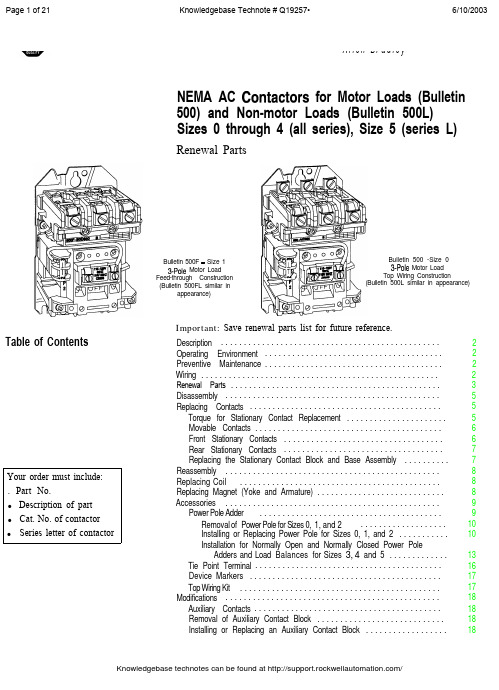
Page 1 of 21 Knowledgebase Technote # Q19257• 6/10/2003Page 2 of 21 Knowledgebase Technote # Q19257• 6/10/2003Page 7 of 21 Knowledgebase Technote # Q19257• 6/10/2003Reassembly Refer to exploded view, Figure 1, for item numbers.1. Place the movable contact support and armature assembly (item 2) in thecontactor base. Attach the contact block cover(s) and tighten screwssecurely (approximately 25 - 30 lbs.-in.).2. Insert the yoke (item 8) into the operating coil (item 7). Place theyoke-coil assembly into the contactor base. The parts are keyed to fitonly one way.3. Replace the coil cover (item 4). If used, check the tie point terminal forproper position. Tighten the coil cover screws securely (approximately25 - 30 lbs.-in.).4. With the movable contact support and armature assembly in the “OFF”position, install the auxiliary contact block(s) (item 6), if used, usinginstructions provided on the auxiliary contact block label.5.Reconnect all control wirings.Replacing CoilReplacing Magnet (Yoke and Armature)Refer to exploded view, Figure 1, for item numbers.1. Remove all wires from coil.2. Remove coil cover (item 4).Note:Auxiliary contact will come off with coil cover.3.Slide out coil (item 7) and yoke (item 8) from movable contact supportand armature assembly (item 2).4. Replace coil and reassemble with yoke.5.Slide yoke and coil back into movable contact and armature assembly.6. Reattach coil cover.7. Reattach wire to coil.8. Reattach auxiliary contact (see p. 19).Refer to exploded view, Figure 1, for item numbers.1. Always replace yoke and armature at the same time.2. Remove contact block cover (item 1), coil cover (item 4), coil (item 7),yoke (item 8), and movable contact support and armature assembly(item 2).3. Replace yoke and movable support armature assembly.4. Reassemble as previously noted.Page 10 of 21 Knowledgebase Technote # Q19257• 6/10/2003Accessories (cont’d) washers, and flat washers according to Figure 6. Tighten screws securely(approximately 16-20 lb.-in. torque).6. Place the movable contact carrier in the contactor base. Attach thecontact block covers on both the controller and the power pole adder.Tighten screws securely (approximately 25 - 30 lb.-in. torque).7. Insert the magnet yoke in the coil (see page 4). Place the yoke-coilassembly in the contactor base. The parts are keyed to fit only one way.8. Replace the coil cover. Check the tie point terminal for proper position.Tighten coil cover screws securely (approximately 25 - 30 lb.-in.)9. With the movable contact support in the “OFF” position, install theauxiliary contact block(s) according to the instructions on the auxiliarycontact block label.10. Properly reconnect all control wiring.Figure 5Right Side AssemblyAdder PoleContact CarrierMovableContactFigure 6Right Side Installation4Rectangular , Slot(Both Sides)Mtg. Screw 01A Installation for Normally Open and Normally Closed Sizes 3, 4, and 5Power Pole Adders and Load BalancersNote:When a single power pole adder (Figure 6) is added to a contactor, a load balancer (Figure 7 and Figure 8) must be added to the oppositeside of the contactor. Each kit contains one power pole adder, oneload balancer, one adder pole contact carrier, and mountinghardware. When installing two power pole adders to a singlecontactor, install a power pole adder on each side and discard loadbalancers.Load Balancer Assembly Procedure for Size 3 (See Figure 7)1. Using a screwdriver, push a special nut into the front nut pocket, makingsure that the extruded rim on the threaded hole is to the inside of thecontactor.2. Position the load balancer against the contactor base. The rectangularprojection on the load balancer fits into the rectangular slot in thecontactor base when positioned correctly. Install the two #8 - 32 X1 - 9/16" screws, lock washers, and flat washers as shown in Figure 7.Tighten screws securely (approximately 16 - 20 lb.-in. torque).Accessories (cont.)Figure 7(Size 3) Left Side InstallationPower PoleAdderReactangul a rSlotSpecial Nut, Pushed intoFront Nut PocketLoad Balancer Assembly Procedure for Size 4 and (See Figure 8)1. Using a screwdriver, push the special nuts into the nut pocket, makingsure that the extruded rims on the threaded holes are to the inside of thecontactor.2. Position the load balancer against the contactor base. The rectangularprojection on the load balancer fits into the rectangular slot in thecontactor base when positioned correctly. Install the three mountingscrews, lock washers, and flat washers according to Figure 8, using thescrew lengths specified for each position. Tighten screws securely(approximately 16-20 lb. -in. torque).Page 15 of 21 Knowledgebase Technote # Q19257• 6/10/2003Page 16 of 21 Knowledgebase Technote # Q19257• 6/10/2003Page 17 of 21 Knowledgebase Technote # Q19257• 6/10/2003Page 20 of 21 Knowledgebase Technote # Q19257• 6/10/2003 Knowledgebase technotes can be found at /Page 21 of 21 Knowledgebase Technote # Q19257• 6/10/2003 Important User Information Because of the variety of uses for the products described in this publication, those responsible forthe application and use of this control equipment must satisfy themselves that all necessary stepshave been taken to assure that each application and use meets all performance and safetyrequirements, including any applicable laws, regulations, codes and standards.The illustrations, charts, sample programs and layout examples shown in this guide are intendedsolely for purposes of example. Since there are many variables and requirements associated with anyparticular installation, Rockwell Automation does not assume responsibility or liability (to includeintellectual property liability) for actual use based upon the examples shown in this publication.Allen-Bradley publication SGI-1.1, Safety Guidelines for the Application, Installation and Maintenance ofSolid-State Control (available from your local Allen-Bradley office), describes some importantdifferences between solid-state equipment and electromechanical devices that should be taken intoconsideration when applying products such as those described in this publication.Reproduction of the contents of this copyrighted publication, in whole or part, without writtenpermission of Rockwell Automation, is prohibited.Throughout this document we use notes to make you aware of safety considerations:Identifies information about practices or circumstances that can lead topersonal injury or death, property damage or economic lossIdentifies information that is critical for successful application andunderstanding of the product.Use only replacement parts and devices recommended by Rockwell Automation to maintain theintegrity of the equipment. It is the user’s responsibility to ensure that the renewal part numberselected is properly matched to the model, series and revision level of the equipment being serviced.Servicing energized Industrial Control Equipment can be hazardous.Severe injury or death can result from electrical shock, burn, orunintended actuation of controlled equipment. Recommended practiceis to disconnect and lockout control equipment from power sources,and release stored energy, if present.Refer to National Fire Protection Association Standard No. NFPA70E, Part 2 and (asapplicable) OSHA rules for Control of Hazardous Energy Sources (Lockout/Tagout) andOSHA Electrical Safety Related Work Practices for safety related work practices, includingprocedural requirements for lockout/tagout, and appropriate work practices, personnelqualifications and training requirements where it is not feasible to de-energize and lockout or tagoutelectric circuits and equipment before working on or near exposed circuit parts.ROCKWELL DISCLAIMS ALL WARRANTIES WHETHER EXPRESSED OR IMPLIED INRESPECT TO THE INFORMATION (INCLUDING SOFTWARE) PROVIDED HEREBY,INCLUDING THE IMPLIED WARRANTIES OF FITNESS FOR A PARTICULAR PURPOSE,MERCHANTABILITY, AND NON-INFRINGEMENT. Note that certain jurisdictions do notcountenance the exclusion of implied warranties; thus, this disclaimer may not apply to you.Allen-Bradley is a trademark of Rockwell AutomationKnowledgebase technotes can be found at /。
- 1、下载文档前请自行甄别文档内容的完整性,平台不提供额外的编辑、内容补充、找答案等附加服务。
- 2、"仅部分预览"的文档,不可在线预览部分如存在完整性等问题,可反馈申请退款(可完整预览的文档不适用该条件!)。
- 3、如文档侵犯您的权益,请联系客服反馈,我们会尽快为您处理(人工客服工作时间:9:00-18:30)。
开关状态
开关的详细开关状态见图3。其中描述了所有可 用的开关元件 安全防护装置打开 SLK-M 和 SLK-E: 安全触点 和 打开 安全防护装置关闭且未锁定 SLK-M 和 SLK-E: 安全触点 关闭。安全触点 打开。 安全防护装置关闭且锁定 SLK-M 和 SLK-E: 安全触点 和 关闭。
执行器的选择
关部件–第1部分:设计通则 ffEN ISO 12100,机械安全 – 一般性设计原则
– 风险评估和风险降低 ffIEC 62061,机械安全 – 与安全有关的电气、
电子和可编程电子控制系统的功能安全
正确使用包括遵守安装和操作的相关要求,特别 是基于下列标准 ffEN ISO 13849‑1,机械安全 - 控制系统安全相
关部件 – 第1部分:设计通则 ffEN ISO 14119(取代EN 1088),机械安全 – 防
护装置的联锁装置 - 设计和选择原则 ffEN 60204-1,机械安全 - 机器的电气设备 – 第
1部分:一般要求
重要! ff用 户 负 责 将 装 置 正 确 集 成 到 安 全 系 功能通过加电驱动,通过弹簧力释 放)
重要!
只有在特殊情况下,经过严格的意外风险评估 后,才可以用作个人保护的防护锁定装置(参 见EN ISO 14119:2013第5.7.1节)!
ff激活防护锁定功能:向电磁线圈施加电压 ff释放防护锁定功能:断开电磁线圈的电压
由电磁驱动的防护锁定功能符合开路电流原理。 如果电磁线圈的电压被中断,则防护锁定功能会 被释放,安全防护装置可以直接打开!
E1 E2
SK ÜK
图 1: SLK 安全开关的功能
安全开关经过专门设计,可以按照EN ISO 13849 2:2013表A4进行内部故障排除。
防护锁定功能的监测
所有型号都配备至少一个用于监测防护锁定功 能的安全触点。当防护锁定功能被释放后, 触 点打开。
安全门监测触点
所有型号都额外配备至少一个安全门监测触点。 根据开关元件的不同,安全门监测触点可采用强 制驱动(触点 )或者非强制驱动。 当安全防护装置打开时,安全门监测触点被致 动。
使用说明书 安全开关 SLK...
正确使用
SLK 系列安全开关是带防护锁定功能(通过低编 码等级的独立执行器实现)的联锁装置。在与可 移动安全防护装置和机器控制器结合使用时,该 安全部件可在执行危险机器功能时防止安全防护 装置被打开。
这意味着: ff只有在安全防护装置被关闭和锁定时,可导致危
险机器功能的启动命令才能生效。 ff除非危险机器功能已经结束,否则不得解锁防
护锁定功能。 ff关闭和锁定安全防护装置不得造成危险机器功
能的自动启动。它们必须通过单独的启动命令 来启动。对于例外情况,请参阅EN ISO 12100 或者相关C标准。
该系列装置还适用于过程保护。
在使用装置前,必须对机器进行风险评估,例如 按照下列标准进行: ffEN ISO 13849‑1,机械安全 - 控制系统安全相
此,必须对安全系统进行验证,例如按照EN ISO 13849‑2。 ff如果使用符合EN ISO 13849 1:2008第6.3节的简 化方法确定性能等级(PL),则多个装置串行连 接可能会降低PL。 ff在 特 定 情 况 下 , 安 全 触 点 逻 辑 串 联 的 性 能 等 级最高可达PL d。更多相关信息可参阅ISO TR 24119。 ff如果产品中包含产品数据表,当数据表的信息 与使用说明书不符时,以数据表的信息为准。
SLK-M 型
(防护锁定功能通过弹簧力驱动,通过加电释 放) ff激活防护锁定功能:关闭安全防护装置;电磁
线圈无电压。 ff释放防护锁定功能:向电磁线圈施加电压。 由弹簧操作的防护锁定功能符合闭路电流原理。 如果电磁线圈的电压被中断,则防护锁定仍然有 效并且安全防护装置无法被直接打开。 如果供电中断时安全防护装置被打开,则随后安 全防护装置会被关闭,且防护锁定功能会被激 活。这可能导致人员被意外锁住。
向转动。 ¨¨防护锁定被释放。
箭头所示方
重要! ff执行器在手动释放过程中不得承受拉伸应力。 ff在使用后,重置辅助释放,旋入和密封锁紧螺钉
关于该主题的更多信息可参阅EN ISO 14119:2013 标准第5.7.5.1节。装置可配备下列释放功能:
辅助释放
出现故障时,防护锁定功能可以通过辅助释放装 置释放,与电磁线圈的状态无关。
当辅助释放被驱动后, 触点打开。必须使用这 些触点生成一个停止命令。
执行辅助释放 1. 旋松锁紧螺钉。 1. 使用螺丝刀将辅助释放装置向
安全预防措施
警告
安全部件用于执行个人防护功能。安装不当或者 旁路连接(篡改)会导致生命危险。 ff严禁对安全部件进行旁路连接、关闭或移除处 理,或以其他方式导致其无效。尤其应遵照EN ISO 14119:2013第7节的说明,降低旁路连接的 可能性。 ff开关操作必须由指定用于该用途的执行器触发。
ff避免因更换执行器导致旁路连接。例如,严格限 制使用执行器以及用于释放的钥匙。
ff安全部件的安装、电气连接和设置只能由具备相 关专业知识的授权人员完成。 小心
环境温度高于40C 时,外壳高温会导致危险。 ff 防止开关被人员触碰或者接触易燃材料。
功能
安全开关允许锁定可移动安全防护装置。 在开关头部有一个旋转凸轮,可通过防护锁紧销 固定/释放。 当插入/移除执行器或激活/释放防护锁定功能 时,防护锁紧销移动,同时,开关触点被致动。 如果凸轮被固定(防护锁定功能激活),执行器 将无法从开关头部退出。出于设计原因,只有当 安全防护装置关闭时,才能激活防护锁定功能( 故障保护锁定机构)。 安全防护装置的位置监测和联锁的监测通过两个 独立的开关元件执行(见图1)。
注意
不适用的执行器会损坏装置。应确保选择正确的 执行器(参见图5中的表格)。
另外要注意安全门半径和紧固选项(参见图4)。
可选用下列型号: ff用于安全开关的执行器S,无插入件。 ff用于安全开关的执行器F,带插入件。
手动释放
有些情况下需要手动释放防护锁定功能(例如在 发生故障或紧急停止时)。在释放后应当进行 功能测试。