中控SmartF说明书
西门子S7-200 SMART PLC产品说明书
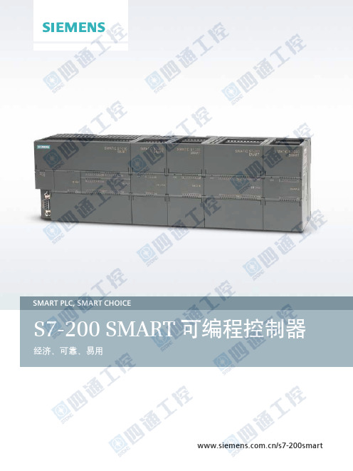
SMART PLC, SMART CHOICES7-200 SMART 可编程控制器经济、可靠、易用/s7-200smart西门子公司一直致力于工业自动化最新技术的研发、推广及应用,在过去的160 多年里,为广大的工业客户带来了可靠高效的自动化产品,完善的自动化解决方案,提高了客户的生产效率,增强了客户的市场竞争力。
西门子SIMATIC 控制器系列是一个完整的产品组合,包括从最基本的智能逻辑控制器LOGO!以及 S7 系列高性能可编程控制器,再到基于 PC 的自动化控制系统。
无论多么严苛的要求,它都能根据具体应用需求及预算,灵活组合、定制,并一一满足。
SIMATIC S7-200 SMART 是西门子公司经过大量市场调研,为中国客户量身定制的一款高性价比小型 PLC 产品。
结合西门子 SINAMICS 驱动产品及 SIMATIC 人机界面产品,以 S7-200 SMART 为核心的小型自动化解决方案将为中国客户创造更多的价值。
2CPU SR60/ST60 技术规范 ........................................... 20数字量模块技术规范 .................................................. 22模拟量模块技术规范 .................................................. 24信号板技术规范 ......................................................... 25热电阻模块技术规范 .................................................. 26通用技术规范 ............................................................ 26安装尺寸图 ................................................................ 27订货号说明 ................................................................ 27模块和信号板接线示意图 ........................................... 28订货数据 . (30)产品亮点 ................................................................... 04CPU 模块 ................................................................... 06信号板 ....................................................................... 08网络通信 ................................................................... 09运动控制 ................................................................... 10人性化软件 ................................................................ 12小型自动化解决方案 .................................................. 14技术规范 ................................................................... 16CPU SR20 技术规范 .................................................... 16CPU SR40/ST40/CR40 技术规范 . (18)目录3SIMATIC S7-200 SMART 产品亮点机型丰富,更多选择提供不同类型、I/O 点数丰富的CPU 模块,单体I/O 点数最高可达60点,可满足大部分小型自动化设备的控制需求。
F智能识别车辆管理系统使用说明书
目录前言 (2)第一章安装环境及驱动说明 (3)1.1安装环境说明 (3)1.2驱动说明 (3)第二章安装 (4)2.1 数据库安装 (4)2.2 安装车辆管理系统 (6)第三章系统配置说明及操作 (11)3.1 系统登录及退出 (11)3.1.1系统登录 (11)3.1.2系统退出 (13)3.2修改密码 (13)3.2.1当前登录密码修改 (13)3.2.2管理员修改密码 (14)3.3 系统基本配置 (15)3.3.1 基本信息设置 (15)3.3.2 磁盘空间监控 (16)3.4 收费标准设置 (16)3.4.1 标准24小时收费 (17)3.4.2 标准通用分段收费一 (18)3.4.3 标准通用分段收费二 (19)3.4.4 标准通用分段收费三 (20)3.4.5 深圳住宅类收费 (21)3.4.6 深圳社会类公共收费 (22)3.5 系统高级配置 (24)3.6 工作站及通道配置 (25)3.6.1 工作站设置 (26)3.6.2 通道设置 (27)3.6.3 不同设备类型参数设置 (32)3.6.4 中央收费设置 (35)3.6.5 通道道闸权限设置 (37)3.7 LED屏配置及内容配置 (39)3.7.1 显示屏设置 (39)3.7.2 显示屏内容配置 (41)3.7.3 剩余车位屏设置 (43)3.8 优惠折扣配制 (47)3.9操作员及权限设置 (50)3.9.1角色权限管理 (50)3.9.2操作员管理 (51)3.10车辆管理操作 (53)3.10.1车辆类型管理 (53)3.10.2车辆信息管理 (54)3.10.3车组限位功能设置 (58)3.10.4黑名单管理 (61)3.11系统图标修改 (62)3.12数据详细报表查询及打印 (64)3.13数据统计报表查询及打印 (67)3.14数据处理 (70)3.14.1 数据库清除 (70)3.14.2 数据库备份还原 (72)3.14.3 数据库迁移 (73)第四章车场监控及管理使用说明 (74)4.1 运行监控 (74)4.2 自动识别操作 (75)4.3出入场手动操作 (76)4.3.1入场手动确认车牌 (76)4.3.2出入场手动开闸 (78)4.3.3 出入场手动抓拍 (78)4.3.4 出场相似车牌 (78)4.3.5 出场手动匹配 (79)4.3.6出场手动校验 (81)4.3.7 免费/异常放行 (81)4.3.8 手动出场 (81)4.4 无车牌车辆出入场处理 (82)4.4.1 无车牌使用配置 (82)4.4.2 无车牌进出操作方法 (83)4.5 中央收费操作 (88)4.6 收费优惠操作 (90)4.7 换班操作 (92)4.8 快捷操作 (93)前言基于车牌识别的停车场管理系统是一种现代化停车场车辆收费及设备自动化管理系统,是将停车场完全置于计算机管理下的高科技机电一体化产品。
中控门禁(F7 F2)黑白屏系列产品用户手册-20120322

黑白屏系列产品用户手册 4.1 系统设置 ............................................................................................ - 26 4.1.1 时间设置.............................................................................. - 26 4.1.2 语言 ★................................................................................ - 26 4.1.3 日期格式.............................................................................. - 27 4.1.4 考勤规则★ .......................................................................... - 27 4.1.5 锁驱动时长 ★ .................................................................... - 28 4.1.6 锁控制人数 ★ .................................................................... - 28 4.1.7 夏令时 ★............................................................................ - 28 4.1.8 部门设置★ .......................................................................... - 30 4.1.9 班次设置★ .......................................................................... - 31 4.1.10 高级设置............................................................................ - 33 4.2 电源管理 ★ ..................................................................................... - 37 4.2.1 电源设置.............................................................................. - 37 4.2.2 定时状态转换 ★ ................................................................ - 39 4.3 通讯设置 ........................................................................................... - 42 4.4 记录设置 ........................................................................................... - 44 4.5 门禁功能设置 ★ ............................................................................. - 44 4.5.1 门禁功能简述 ...................................................................... - 46 4.5.2 门禁验证流程 ...................................................................... - 47 4.5.3 门禁功能介绍 ...................................................................... - 48 4.5.4 胁迫报警设置 ...................................................................... - 57 4.5.5 错按报警.............................................................................. - 59 4.5.6 组验证类型 ★ .................................................................... - 60 4.6 自动检测 ............................................................................................ - 61 5.语音设置 ★ ................................................ - 62 5.1 通过设备设置 ................................................................................... - 62 5.2 通过Web Server设置 ....................................................................... - 65 6.U盘管理 / SD卡管理 ★ ...................................... - 67 6.1 下载考勤数据 ................................................................................... - 67 II
艾顿智能3路风扇速度控制器说明说明书
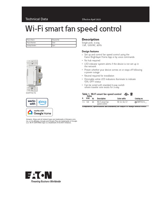
DescriptionSingle pole, 3-way, 1.5A, 120V/AC, 60HzDesign features•Set up and control fan speed control using theEaton Brightlayer Home App or by voice commands • No hub required•LED indicator system alerts if the device is not set up in the network•Preset whether your device comes on or stays off following a power outage• Neutral required for installation•Dimmable white LED indicators illuminate to indicate (ON, OFF) status•Can be wired with standard 3-way switch where traveler wire exists for 3-way.EWFFSC15Project Name:Prepared By:Project Number:Date:Catalog Number:Type:T able 1. Wi-Fi smart fan speed controlCompliances, specifications and availability are subject to change without notice.Rating DescriptionColor suffixCatalog no.AV/AC Hz1.512060Wi-Fi smart fan speed controlW, C2, C6, C7Amazon, Alexa and all related logos are trademarks of , Inc. or its affiliates. Google and Google Play are trademarks of GoogleLLC. Wi-Fi CERTIFIED logo is a trademark of the Wi-Fi Alliance.Wi-Fi smart fan speed control2EATON/connectedhome Technical DataEffective April 2023Wi-Fi smart fan speed controlCatalog No.EWFFSC15PerformanceMaximum amperage: 1.5ARating:120V/AC, 60HzInstallation & programming For installation and programming the device, see the Wi-Fi Smart Fan Speed Control Quick Start Guide included with product.Testing & code compliance cULus Listed 244B. NOM Certified. Complies with FCC Part 15, Class B.TerminationsFan speed controller has screw terminals for line, load, ground, neutral and traveler 3-way wire Material characteristics Flammability: Meets UL94 requirements; V2 rated Temperature rating: 32°F to 104°F (0°C to 40°C)Warranty2-year limited product warrantyEaton’s Wi-Fi smart fan speed control replaces regular switches (where a neutral is present) to provide local and remote control for ceiling fans. The fan speed controller can be remotely controlled and the user can create routines, schedules and group devices using the Eaton Brightlayer Home App. Eaton’s Wi-Fi smart fan speed control has additional features such as a selection of 3 fan speed controls (High, Medium, Low).ApplicationsProject Name:Prepared By:Project Number:Date:Catalog Number:Type:T able 2. SpecificationsCompliances, specifications and availability are subject to change without notice.Figure 1. EWFFSC15For ordering devices, include Catalog No. followed by the Color Suffix: W (White),C2 (Color Change Kit: LA, W, V), C6 (Color Change Kit: W, RB, SG), C7 (Color Change Kit: B, BK, GY)Decorator series color options:(White)C2 Color KitLA (Light Almond), W (White),V (Ivory)C7 Color KitB (Brown), BK (Black), GY (Gray)C6 Color KitRB (Oil Rubbed Bronze), W (White),SG (Silver Granite)T able 3. Color ordering information3EATON /connectedhome Single location control installationWi-Fi smart fan speed control Technical DataEffective April 2023Project Name:Prepared By:Project Number:Date:Catalog Number:Type:Certifications & compliancesKEY:cULusNOMFCCRelated productsWi-Fi smart productsEWFD30, EWACD, EWFTRCR15Compliances, specifications and availability are subject to change without notice.WallplatesPJS26, PJS262Single Location Control Installation (requires one Wi-Fi Fan Speed Control)3-Way location control installation Electrical Sector 1123 Hwy 74 SPeachtree City, GA 30269United States /WifiSmartElectrical Sector Canada Operations 5925 McLaughlin RoadMississauga, Ontario, L5R 1B8CanadaEatonCanada.ca/WifiSmartElectrical Sector Mexico Operations Carr. Tlalnepantla -Cuautitlan Km 17.8 s/n Col. Villa Jardin esq.Cerrada 8 de MayoCuautitlan, Mexico CP 54800Mexico Eaton.mx/WifiSmartEaton1000 Eaton Boulevard Cleveland, OH 44122United States Eaton is a registered trademark. All other trademarks are property of their respective owners.© 2023 EatonAll Rights Reserved Printed in USAPublication No. TD610147EN April 2023。
模块使用说明书

注意事项:1,使用时请轻拿轻放,切勿扔摔。
2,轻拨轻推电源开关。
3,电池电压最好不要低于2.7V,因为cc2430芯片分辨哪个按键被按下时,是通过模拟量来分辨的,如果电压低于2.7V时,容易造成按键分辨不准确。
虽说CC2430芯片手册上说可以在2.0V工作,但那是最低电压,最好不要在芯片的最低电压点来工作。
最好使用碱性干电池,如南孚牌的等等。
4,做按键闪灯实验时,请不要太快速连续按键,按键动作尽量到位可靠,连续按键的间隔时间最好不少于5秒。
5,当使用电池供电的时候,请不要用仿真器给模块供电。
6、最好也好多看看光盘内的资料,在改动跳线帽等相关硬件连接的时候,请先多看看原理图。
最好在你熟悉了模块之后再改动跳线帽。
7、一定要顺着本模块使用说明书pdf文档仔细往下看,请不要急于求成,一定要仔细的照着本文档仔细操作,切不可急躁!!!初步认识模块篇:一、初步测试模块:cc2430模块套件到你手上的时候,里面下载了个zstack-1.4.3-1.2.1协议栈的sampleapp的demo工程。
第一步:先给两个模块的电池盒上好干电池。
第二步:观察下两个模块,两个模块两边排针上的跳线帽的跳法有一些不同,请仔细观察。
1、如果你购买的两个模块都是不带屏的模块,那么请仔细看下模块上的P2(2x10双排针),其中有一个模块的P2上的P02、P03针(P2双排针的内侧)是被一个跳线帽短接起来的。
那么这个模块在下载了zstack-1.4.3-1.2.1协议栈的sampleapp的DemoEB工程后,这个模块就被协议栈认为是协调器设备了。
但是一定要注意:在zstack-1.4.3.-1.2.1协议栈的其他工程中,是不会认为cc2430芯片的P02和P03被短接起来就是协调器的。
只有在zstack-1.4.3-1.2.1的sanpleapp的DemoEB工程中,代码才认为cc2430芯片的P02和P03被短接起来后就是协调器。
如果是带屏的模块,则屏板上右侧的P7双排针的第10针和第12针是被一个跳线帽连接在一起的,这样的模块zstack-1.4.3-1.2.1协议栈中sanpleapp的DemoEB工程中是被程序认为是协调器,而在zstack-1.4.3.-1.2.1.其他工程中,是不会被认为是协调器模块的。
smart中文说明书
1.除去压力调节器的运输包装。
使用前必须除去位于调节器黑色的可拆卸的上盖下面的泡沫塑料。
检查标气及过程气是否连接紧固,安装位置是否准确。
检查运载气的连接及所有用于双量程的所有连接。
检查标气的质量,并在菜单中输入正确的值。
只有在已知标气的气体成分时,才能根据标气中的每个气体成分计算出正确的华白指数。
推荐使用推销商提供的有检定值的气瓶。
打开设备电源,将自动进行点火,这些只有在关门的情况下才可进行。
设备开始运转,预热时间过后(20-30分钟,第一次试运转是从冷状态开始的)将会得到过程气的正确热值。
CW2000内的计算机程序已在工厂中完成预设定(见与设备一起提供的数据清单),测量范围及所有其他特别选项都已考虑进去了。
设备开始运转后,燃气的压力将显示为4mbar,冷空气的压差也将是4mbar。
升温时间过后,仪表将在显示器上显示热值、华白指数及比重。
在图形界面上将开始显示在线测量值的走势趋势。
在工厂中软件的缺省设置为产生这种可视的走势图。
2.软件软件由许多菜单级组成,并可通过薄膜键盘进入。
所有相似的操作可进入一系列菜单中完成。
一个菜单条位于显示器的底部,菜单键相应的功能拟态地显示在屏幕的底边上。
菜单按钮(1)区是用于连接到下一个更高的菜单级。
菜单按钮(5)是无论在任何菜单级都返回到开始菜单。
处理器实现的功能都是辅助的,在通过菜单完成功能时应考虑到这点。
3.显示器布置图图1:显示器1 主菜单键 6 启动/停止键2 历史趋势图键7 输入数据键3 数据显示区8 燃烧器窗口4 信息区9 状态显示灯5 返回主菜单键10 位置键4.标定标定就是输入华白指数和比重。
在标准配置时,该设备含有一个测量范围及一种标气。
对于双量程需要一种或两种标气,应根据两个量程的重叠范围,如果重叠范围较大,一种标气就足够了,这将根据工厂具体的最终标定情况来决定。
标定数据输入华白指数及比重。
如果标气供应商仅提供气体成分的百分数,那么这两个值必须根据标气的成分来计算。
FT1A SmartAXIS 微型PLC控制器系列说明书
IDEC FT1A SmartAXISPresenting FT1A, the newest family of SmartAXIS controllers from the industry’s original manufacturer of micro PLCs. FT1A controllers deliver affordability without compromise. Features and functions are already built in, so engineers can now enjoy more versatility and more choices for their automation needs than ever before.Designed to give you the most bang for your buck, these simple, powerful controllers deliver an exceptional value. FT1A controllers are available with 12, 24, 40, or 48 I/O, while a 3.8-inch HMI + PLC with sophisticated features and a super-bright LCD screen is also available.All FT1A controllers meet the highest industry standards for quality and safety. The FT1A SmartAXIS family is CE compliant, cULus listed, has an ABS type approval and is Class I Division 2 rated for hazardous locations. Whatever your application requires, the FT1A SmartAXIS family has a solution!Value. Versatility. The New Breed of Controller!The ideal solution for a variety of applications.• Relay output type equipped with 10A contact, so no interposing relays required.• Transistor output type equipped with 300mA per channel.Digital, Analog and High-speed Inputs 8 built-in DC inputs• 2 inputs (I6 and I7) can be configured as 0-10V DC or 4-20mA analog inputs (transistor output models) – 10-bit resolution • 4 high-speed counters – Up to 10kHzUp to 2 analog expansion adapters can be configured Models)2 built-in 0-10VDC, 4-20mA analog outputs.Harsh Enviroments• Class I, Division 2 for hazardous locations• -20 to 55°C operating temperature (color models)IP66f (water and oil tight), NEMA 4X (indoor) and 13RJ45 Ethernet Port• Supports remote Ethernet communication and Modbus TCP .• Communication with IDEC or other PLCs also supported through the Ethernet port.5MB Screen Editing Memory Provides users with more flexibility and stress-free programming.Actual Size800.262.4332/FT1ALarge Programming MemoryWith 47.4KB of logic controls programming memory, complex PLC programs can be constructed without much restriction. And with 5MB of configuration memory for the display, a unique and professional display interface can be easily configured.10A Relay OutputsWith 10A contact ratings on all four of the relay outputs, the FT1A Touch can be directly connected to a solenoid valve or motor, which eliminates interposing relays and reduces wiring.Control FunctionsFast Processing SpeedBasic instructions can be processed in 1850µs per 1000 steps of programming.Data LoggingCritical data can be saved and logged into a USB memory stick then retrieved over an Ethernet connection or by removing the USB memory stick from the FT1A Touch and inserting it into a laptop or PC.Easy Program File TransferProject files can be transferred between a USB memory stick and the FT1A Touch. It is a quick and convenient way for an OEM to program multiple units and for users to quickly update ladder and HMI programs.Digital and Analog InputsThe FT1A Touch is equipped with 8 digital inputs, two of which can be configured as 0-10V DC or 4-20mA analoginputs with 10-bit resolution, reducing overall system cost.Remote I/OUp to three FT1A controllers (24, 40 and 48 I/O) can be configured as remote I/O slaves for the FT1A Touch,expanding your system’s potential. A maximum of 158 I/O can be achieved.Analog Expansion CartridgesUsing analog expansion cartridges, FT1A Touch can accept 0-10V DC, 4-20mA, RTD and Thermocouple inputs, with 12 to 15-bit resolution.PID ControlsWith an improved PID algorithm and easier-to-configure dialog box, PID controls can be monitored using a single screen. Advanced PID control functions, such as auto-tuning, ARW (anti-reset windup) and bumpless transfer, are also supported.High-speed CountersWith 8 built-in inputs, 4 can be configured as high-speed counters, with a maximum frequency (range) of 10kHz for single-phase or 5kHz for dual-phase.Master 14-I/O type 65,536 TFT Color LCDWith so many color combinations, an intuitive and crisp graphical user interface can be constructed with unparalleled visibility.Super-Bright LEDThe 65K TFT color unit is rated at 400cd/m 2, while the monochrome unit is rated at 740cd/m 2. With 32 levels of brightness control, the backlight can even be adjusted according to the surrounding conditions.Drivers for IDEC and other PLCsFT1A Touch can easily be configured to communicate with IDEC or other PLCs such as Siemens, Automation Direct, Mitsubishi, Omron, and more.Display FunctionsEthernet ConnectivityWith the embedded RJ45 Ethernet port, FT1A project files can be remotely uploaded or downloaded over an Ethernet connection. Critical logging data can also be retrieved quickly.Modbus TCP or RTUThe built-in Ethernet ports allow the FT1A Touch to be configured as a Client (Master) or Server (Slave) on the Modbus network. Modbus RTU (Master/Slave) is also supported. With these capabilities, FT1A Touch can communicate with other PLCs or devices using Modbus protocol.Ladder Program and I/O statusLadder programs can easily be monitored and controlled on the 3.8” (3.7”monochrome) display. It is a unique tool to debug the system without using WindLDR software and a PC. I/O status and any control parameter such as data register, timer, and internal relay can also be monitored and controlled.Fast Start-upOnce power is applied to the FT1A Touch, it takes only 3 seconds for it to be fully functional. The fast start-up allows for fast, easy debugging and stress-free operation.3 sec800.262.4332/FT1ASmart LCD ScreenNon-LCD ModelUSB mini-BMemory CartridgeThe optional memory cartridge can be used to easilytransfer programs from the internal ROM memory of FT1Acontrollers to a memory cartridge or vice versa. It’s aconvenient method to update the PLC program in the field.FT1A ControllersFT1A controllers are designed for a range of applications that demand powerful and abundant features. Availablewith 12, 24, 40 and 48 I/O with and without embedded LCD/keypad, these controllers enable engineers to designcost-effective solutions.Note: Features available on specific models.See page 14 for selection guide.Universal Voltages24V DC or 100-240V ACActual Size800.262.4332/FT1AThe FT1A controller with relay outputs is equipped withfour 10A relay contacts. The transistor outputs model isalso equipped with two 100kHz high-speed outputs forsimple positioning controls. With remote I/O capability,additional outputs can easily be added.Real-Time ClockEvery FT1A controller is equipped with an embedded real-timeclock for time-controlled applications. With the built-in, real-time clock, log data can also be tracked and, with just a click,daylight savings time can easily be setup.RJ45 Ethernet PortThe embedded Ethernet port on the FT1A controllersprovides users with easy access for remote maintenance andcommunication. It also supports industry standard ModbusTCP protocol. With Ethernet Remote I/O capability, the FT1Acontroller’s I/O can be easily expanded.RS232C and RS485 PortsUp to two RS232C and/or RS485 communication cartridgescan be plugged into the FT1A controllers to allow the PLC tocommunicate with other serial devices. It also supports industrystandard Modbus RTU protocol.Large Programming MemoryWith up to 47.4KB (11,850 steps) of programming memory,FT1A controllers have enough memory for even complexPLC programming.SD Memory CardWith the embedded SD memory slot, critical data can beeasily logged and retrieved over Ethernet connections orsimply remove the SD card and plug it into your PC.I/O CPU) supports Modbus TCP and Modbus RTU, making communication with other devices a breeze.Ethernet ConnectivityThanks to the embedded RJ45 Ethernet port (on all models except 12 I/O), FT1A controllers can be easily accessedfrom remote locations. Using WindLDR software, PLC programs can be updated remotely and critical parameters monitored and controlled. Remote connectivity is a critical part of today’s control environment, and FT1A controllers meet every challenge with fast, easy, and reliable Ethernet connectivity.SD Memory CardFT1A 40 and 48 I/O controllers are equipped with an SD memory slot for data logging. Memory cards up to 32GB are supported. Log data is time/date stamped and stored in .CSV format, making it simple to review and analyze critical system data.From Connecting to Remote AccessFrom connectivity to remote access to visual display, FT1A leads the way with versatile, full-featured controllers. No other controllers offer such a broad range of capabilities at such a competitive price.Smart LCD DisplayWith the embedded LCD screen, I/O status, system menus, customized dynamic messages, and bar-graph readouts can all be config u red and displayed. Ladder programs can be displayed and controlled as well. You can configure up to 50 customized messages, all with dynamic values (24 digits by 4 lines max.). The backlight can be turned on or off. Scrolling and flashing are also supported.48-I/O type Built-in Analog InputsThe FT1A controllers support up to 8 built-in, 0-10V DC analog inputs with 10-bit resolution, depending on the model. Having the option to configure the analog inputs on the CPU saves you time, space and money.100kHz, High-Speed Counters and OutputsModels with transistor outputs feature two 100kHz high-speed outputs for positioning control and all FT1A controllers are equipped with up to six 100kHz high-speed counters.10 Amp Relay ContactsFT1A controllers with relay outputs offer 10 Amp rated contacts. Traditional PLC relays are only rated for 2 Amps. Therefore, FT1A controllers reduce the need for, and spare you the cost of, using interposing relays.Built-in Real Time ClockEquipped with a real-time clock for use with any time-controlled applications, FT1A controllers have built-insupport for US, Canadian, European, and Australian daylight savings time. The option for the user to configure their own custom daylight savings schedule is also available, providing the utmost in flexibility.USB Maintenance PortA convenient USB mini-B maintenance port is standard on all FT1A controllers, which means any standard Type A to mini-B USB cable can be used. No special cable is necessary.800.262.4332/FT1AA Complete Automation Suite: All-in-one Configuration SoftwareAutomation Organizer (AO) is a powerful software suite containing WindLDR PLC programming software, WindO/I-NV2 HMI configuration software, WindO/I-NV3 FT1A Touch configuration software, and WindCFG system configuration software. AO is an all-in-one automation software package for IDEC PLCs and IDEC HMIs. The news gets even better, because AO software upgrades are always FREE.WindO/I-NV3WindO/I-NV3 is our exclusive configuration software for the FT1A Touch. Using the same platform as WindO/I-NV2 HG HMI program m ing software, WindO/I-NV3 provides users with the same intuitive experience. Users can easily display alarm screens, trend and bar graphs, scrolling texts and meters. With thousands of industry-standard bitmap libraries, creating a professional interface is just a click away.WindLDRAll IDEC PLCs—including the FT1A family—are programmed with WindLDR software. This icon-driven programming tool combines logic and intuition with an incredibly easy-to-use interface. Offline simulation, I/O Force and program bookmarks are just some of the standard features you’ll find in WindLDR. Newly added for FT1A are Function Block Diagram (FBD) and Script programming. Over the years, WindLDR has proven to be the most user-friendly, intuitive software available for beginners and advanced programmers alike.Simulation ModeWindLDR allows you to simulate ladder and Function Block Diagram (FBD) programs in FT1A. You can easily test and verify functionality of your ladder and FBD programs without having to connect any hardware.Comment Download SettingsThe comment download settings allow you to choose whether to download Tag names, rung comments, custom monitor dialog boxes or file names. The biggest advantage of utilizing these settings is that once a program is retrieved from the PLC, all these important parameters will be available.Function Block and ScriptingIn addition to ladder logic, WindLDR now supports Function Block Diagram (FBD) and Script programming. With the FT1A controllers, you now have the flexibility and convenience of programming using any or all of these methods.Free 30-Day DemoCurious to see how an IDEC FT1A SmartAXIS controller might complement your design? Find out for yourself!Just go to /download and download your free 30-day demo.800.262.4332/FT1ATouch Starter KitsIn place of insert code for display type: C = color, M = monochromeGeneral SpecificationsDisplay SpecificationsOperation Specifications800.262.4332/FT1AAnalog Cartridge Specifications (Touch T ransistor Output Model)© 2015they IDEC Corporation. All Rights Reserved. Catalog No. FT9Y-B100-2 04/15 PDF OnlySpecifications and other descriptions in this catalog are subject to change without notice.USAIDEC Corporation Tel: (408) 747-0550********************AustraliaIDEC Australia Pty. Ltd.Tel: +61-3-8523-5900*************.comCanadaIDEC Canada Ltd.Tel: (905) 890-8561*************.comJapanIDEC Corporation Tel: +81-6-6398-2571 *****************.jpChinaIDEC (Beijing) Corporation Tel: +86-10-6581-6131IDEC (Shanghai) Corporation Tel: +86-21-6135-1515************.comIDEC (Shenzhen) Corporation Tel: +86-755-8356-2977GermanyIDEC Elektrotechnik GmbH Tel: +49-40-253054-0***************Hong KongIDEC (H.K.) Co., Ltd.Tel: +852-2803-8989 ************.comSingaporeIDEC Asia Pte. Ltd.Tel: +65-6746-1155 ************.comTaiwanIDEC Taiwan Corporation Tel: +886-2-2698-3929 ***************.comThailandIDEC Asia (Thailand) Co., Ltd. Tel: +662-392-9765 *************.comUnited KingdomIDEC Electronics Ltd.Tel: +44-1256-321000 *************.com800.262.4332Get Intensive Hands-on PLC and HMI TrainingPLC/HMI Training KitSmartAXIS Training KitIn-class Training KitsLooking to improve your knowledge of PLCs and HMIs? IDEC’s training course combine hands-on instruction and real-world examples. Some of the covered topics include:The training course covers programming for SmartAXIS and MicroSmart Pentra PLCs, SmartAXIS Touch (HMI+PLC) and HG series HMIs and includes Q&A sessions with our experts to discuss your specific application.Choose from five kits featuring introductory-level products all the way up to our most advanced HMIs and PLCs! For detailed information, our current schedule and to sign up for a class, visit .• Start/stop and latching circuits • Timers and counters• Modbus/TCP communications • Email/Text and web page setup • PID configuration• Pushbuttons, pilot lights • Data displays and data inputs • Graphics and animation • Alarms and passwords • Remote control and monito r。
F门禁管理系统用户手册
F6门禁管理系统用户手册目录1.系统软件 (2)2.服务器连接 (2)3.系统管理 (3)3.1系统登录 (3)3.2修改密码 (3)4.联机通讯 (4)4.1读取记录 (4)4.2自动下载数据 (5)4.3手动下载数据 (5)4.4实时通讯 (6)4.5主控设置 (6)5.辅助管理 (8)5.1服务器设置 (8)5.2系统功能设置 (9)5.3读写器设置 (10)5.4电子地图 (13)6.查询报表 (14)6.1开锁查询 (14)7.帮助 (18)7.1帮助 (18)1.系统软件图1 门禁管理软件主界面F6版门禁管理系统的软件界面如上图,顶端菜单栏包括“系统管理”、“联机通讯”、“辅助管理”、“查询报表”和“帮助”菜单;左侧快捷按钮包括“系统管理”、“联机通讯”、“辅助管理”、“查询报表”、“状态”等主功能项,每个主功能项包含几个子功能,在主界面上可以不依靠主菜单,就可在主界面中找到每个功能的快捷按钮。
以下按照菜单栏的顺序进行介绍。
2.服务器连接如图2点击设置则进入远程服务器设置,此处的远程服务器IP地址不是指数据库服务器,而是指中间层Fujica Server服务管理器的IP地址。
图2 服务连接图2 远程服务器设置3.系统管理3.1系统登录系统默认的操作员卡号为“0001”,密码为“admin”,上班人员输入管理卡号和密码后可以进入系统,进行授权给他的一切操作。
图3 系统登录3.2修改密码修改密码是指操作员登录成功后,可以修改自己登录的密码。
先输入操作员的旧密码,再输入新密码并确认,则密码修改成功。
图4 修改密码4.联机通讯4.1读取记录该功能用于读取在线的门禁读写控制器中的记录。
点击菜单中的“读取记录”,选择好门禁后,对所选择的门禁中的记录进行读取,并上传至服务器数据库中。
为了确保记录数据不丢失,也可以随时进行该项操作。
如图5为读取记录图5读取记录4.2自动下载数据该功能是对ID卡有效的卡号进行下载、ID或IC卡的挂失/恢复等卡片数据下载功能。
1.0 Smart Home Controller 快速安装手册说明书
Smart Home ControllerQuick Installation ManualTable of contents1.Introduction (4)1.1.Safety instructions (4)1.2.Intended use (4)1.3.About this document (4)1.3.1.How to start (4)1.3.2.Troubleshooting (4)1.3.3.Feedback (4)2.Installation (5)2.1.Smart Home Controller Installation (5)2.2.MRF xComfort Network Installation (5)3.Quick setup (7)3.1.Connect to the Web Admin Console (7)3.2.Import Data Points (8)3.3.Adjust available Devices (8)3.4.Create Users (10)3.5.Set Time Zone (11)3.6.Activate the Smart Home Controller (12)3.7.Create Zones and assign available Devices (13)3.8.Enable and setup needed Functions (14)3.9.Download and connect the App (IOS) (15)3.10.IOS App: Start the Temperature Control (16)3.11.IOS App: Create Light Scenes (17)4.Troubleshooting (18)4.1.LED Indicators on the Smart Home Controller Box (18)4.2.How to restore the default admin password (18)4.3.How to restore the SHC network settings (19)4.4.Ways to recover the SHC (19)4.5.Ways to connect to the SHC Web Admin Console (19)4.5.1.Directly via a browser and IP address (19)4.5.2.Via Bonjour (MAC) (19)4.5.3.Via UPnP (Windows) (20)4.5.4.Via MRF (20)4.6.Default admin password? (20)Appendix A Feedback form (21)1. Introduction1.1. Safety instructionsThis document contains important warnings and safety instructions which must be observed and followed by users. Failure to follow these warnings and safety instructions will put the fault-free operation of the Smart Home Controller at risk.1.2. Intended usexComfort products are designed for use in private homes and similar, fixed electrical installation systems. Applicable standards can be found in the CE declarations of conformity included in the mounting instructions supplied with each product.1.3. About this documentThis manual is intended for trained Installers only and describes the installation and configuration of the Smart Home Controller. Following this manual will ensure a successful installation1.3.1. How to startIf you are new to the System, start with the chapter “How things work” in the Smart Home Controller Reference Manual to understand the Smart Home Controller concept and basics. Important is to know how this system works based on Zones and the way functionality is provided. This will directly affect the way the User can control his home.If you are already familiar with the system, start directly with chapter 2 Installation and 3 Quick setup.1.3.2. TroubleshootingIn case of problems check chapter 4 Troubleshooting.1.3.3. FeedbackPlease feel free to support us with any suggestions or feedback. Please use the feedback form in appendix A.2. InstallationFollow the instructions in this chapter to install the Smart Home Controller and setup the xComfort network.Installation steps:• Smart Home Controller Installation• MRF xComfort network Installation2.1. Smart Home Controller InstallationFind an appropriate location for the Smart Home Controller. This location must be dry and free of other electric equipment that could disturb the working of the Controller. Keep in mind that the SHC does have an internal antenna for the xComfort RF network.ATTENTION! Find an appropriate location for the SHC. The SHC does have aninternal antenna for the xComfort RF module. Avoid disturbance from other equipment like WiFi routers. Minimum distance > 0,5m.Installation steps:1. Use the mounting holes in the SHC to screw the SHC to the wall.2. Connect the SHC to your home network using a network cable.3. Connect the power adapter to the SHC and switch on the power.2.2. MRF xComfort Network InstallationUse the MRF xComfort Network Configuration Tool to create and setup the xComfort Network and create a Datapoint file so that the SHC recognizes all the xComfort Devices in the network.ATTENTION! Use MRF tool version or higher: Eaton RF-System V2.19.Installation steps:1. Make a plan of all the functionality in Zones needed.2. Open the MRF Tool and create the MRF project.3. Scan the network for xComfort Devices.4. Configure the Device Settings if needed.Checklist:Door (Switch) Actuator: Function: Off / On with switch off delay. Shutter Actuator: Runtime. Dimming Actuator: Dimming time, Dimming limits. Binary Inputs: Mode 2, Cyclic sending.Analog Inputs: 0 – 10V, Cyclic sending.Temperature Sensors: Send Temperature value, Cyclic sending. By default the Climate Function expects within every hour a temperature value. Set cyclic sendingvalue to 55 minutes.5. Connect all xComfort Devices to the Smart Home Controller. See Figure 1: MRF Projectexample.ATTENTION! To maintain the correct status of the Actuators it is important toconnect all xComfort Actuators directly to the Smart Home Controller or an ECI. Find detailed information in the Smart Home Controller Reference Manual.6. Specify a clear name for each Device.7. Scan reception quality of all devices. Calculate and check all connections.8. Load the configuration into the devices.9. Create datapoint-file for the SHC and select Transmission: download by RF.10. Save project.Figure 1: MRF Project example3. Quick setupFollow the instructions in this chapter to do a quick setup of the Smart Home Controller with a basic configuration. Find additional information and configurations in the Smart Home Controller Reference Manual.Setup steps:Connect to the SHC Web Admin ConsoleImport Data PointsAdjust available DevicesCreate UsersSet Time ZoneActivate the Smart Home ControllerCreate Zones and assign available DevicesEnable and setup needed FunctionsDownload and connect the App (IOS)IOS App Function settings3.1. Connect to the Web Admin ConsoleConnect to the Web Admin Console via MRF.Steps:1. Open MRF and load the project2. Right click on the SHC and select: IP-Address3. Click on the link: Address4. The browser opens with the login page:5. Login with:- Username: admin- Password: admin6. The Web Admin Console is available3.2. Import Data PointsDuring the Installation the Data Points are already uploaded to the Smart Home Controller via MRF. If not, check chapter 2.2 MRF xComfort Network Installation.Admin Console navigation: 1. System -> DatapointsSetup steps:1. The default Internal RF Interface indicates the new datapoints:2. Click: Import Data Points3. Please wait until the popup shows the process is ready:ATTENTION! Do not interrupt this step.4. Click: OK5. Status indicates:3.3. Adjust available DevicesChange the name and purpose of imported devices if needed. Specify always the unit and ratio for Impulse Counters and Analog Inputs.Web Admin Console navigation: 1. System -> DevicesSteps:1. Select one Device of the available Devices on the left. Example:2. Change the Device parameters on the right. Example:3. Click: Save4. Repeat previous steps for each Device5. If finished, Click:6. Please wait until the popup shows the process is ready:ATTENTION! Do not interrupt this step.7. Click: OK3.4. Create UsersWeb Admin Console navigation: 1. System -> UsersFirst: Change always the default admin password!Steps to change the admin password:1. Click for User admin the Change Password Icon:2. Change and remember the password:3. Click: Ok4. Change the language if needed (Used for the Admin Console)Add at least one Advanced User:1. Specify User credentials:2. Click: Add3. The new User is shown in the list of UsersCheck options: Advanced and: RemoteAdd at least one normal User to control the system:1. Specify User credentials:2. Click: Add3. The new User is shown in the list of UsersIf needed check option: Remote3.5. Set Time ZoneWeb Admin Console navigation: 1. System -> Time Zone Steps:1. Check Time Zone Settings:2. Change settings if needed. Normally: Country and: City3. Click: Save3.6. Activate the Smart Home ControllerActivate the SHC for remote access and new software updates.Admin Console navigation: 1. System -> Remote AccessSteps:1. Check if there is Internet Access:2. Click: Activate:3. Read and Accept the Terms And Conditions: Accept4. Please wait until the popup disappears:5. Enable: Global Remote Access6. Refresh the page to check the connection status:7. Please make a note of the received Remote Access ID to connect remotely3.7. Create Zones and assign available DevicesAs defined by the Customer create the Zones and add the Devices to these Zones. Create general Zones if needed.Web Admin Console navigation: 2. ZonesSteps:1. Click: New2. Define a Zone name:3. Click: OK4. Select one or more Available Devices on the right side (Hold shift or ctrl):5. Click to add the selected Devices to the Zone:6. Added Devices are shown in the left screen:7. Repeat all steps for each Zone3.8. Enable and setup needed FunctionsEnable the Functions required by the Customer in each Zone.Web Admin Console navigation: 3. FunctionsSteps:1. Select the Zone (Per default the Functions are disabled):2. Enable the required Functions for this Zone (Function properties appears):3. Adjust specific properties if needed4. Repeat all steps for each Zone3.9. Download and connect the App (IOS)This example is based on the iPhone.Figure 2: Download AppOpen the App Store: Search for: EatonInstall and open the AppFigure 3: Connect to Smart Home ControllerClick: ConnectSelect your controllerLogin as advanced User3.10. IOS App: Start the Temperature ControlSelect the Climate Function:Figure 4: Start the Temperature ControlSelect a predefined mode Click: Edit Select: HeatingAnd: CloseThe question mark indicates that no temperature value has been received yet. For additional information see the Smart Home Controller Reference Guide. Start the Temperature Control in every Zone with a Climate Function via the “edit” button.3.11. IOS App: Create Light ScenesTo create a Light Scene, select the Status & Control Function to set the preferred light settings.Figure 5: Create a Light Scene 1Select Status & Control Set preferred LightsSelect Scene FunctionAnd click: EditClick:Figure 6: Create a Light Scene 2Define a Scene nameAnd click: OKCheck light settings And return to Zone Button created4. TroubleshootingFind in this chapter information and instructions to solve problems. Consult also the latest FAQ to find answers to questions.4.1. LED Indicators on the Smart Home Controller BoxPower LED:o Green: Power ON, the System is operational.o Orange: The System is booting.Network Connection LED:o Green: Remote Server Connection.o Orange: Internet connection. The SHC is not activated yet.o Red: No Internet connection. Check your internet connection via a PC or laptop.RF Traffic LED:o Blinking Green: RF traffic.System Message LED:o Green: There are no new messages in the Mailbox.o Yellow: New Warning Message in the Mailbox.o Red: New Error Messages in the Mailbox.Battery Status LEDo Green: All batteries are OK.o Yellow: At least one battery is weak. Consider to replace batteries.o Red: At least one battery one battery is very weak or empty. Replace batteries.4.2. How to restore the default admin passwordThis symbol indicates the recovery button on the Smart Home Controller Box.Use a small pin to access this button.Press the button on the Smart Home Controller for 15 seconds (power LED flashes green and will finally change to orange), system will reboot. Wait until the LED is green. Also the network settings will be set to DHCP.4.3. How to restore the SHC network settingsThis symbol indicates the recovery button on the Smart Home Controller Box.Use a small pin to access this button.Press the button on the Smart Home Controller for 15 seconds (power LED flashes green and will finally change to orange), system will reboot. Wait until the LED is green. Also the admin password is set to default.4.4. Ways to recover the SHCThe Smart Home Controller can be recovered in the following ways:•Power Off the System by removing the power plug for 1 minute and reconnect.•Reboot the Smart Home Controller via the Web Admin Console.•Set the Smart Home Controller back to factory settings. Reconfigure everything.•Reset internal RF Module password and datapoint list. Use MRF to reprogram. Admin Console navigation: 1. System -> Firmware4.5. Ways to connect to the SHC Web Admin Console4.5.1. Directly via a browser and IP address1. Open a browser2. Open the login page: http://<SHC IP address>:3. Login with:- Username: admin- Password: admin4. The Web Admin Console is available4.5.2. Via Bonjour (MAC)1. Open: Safari2. Click the Bookmark icon:3. Select Bonjour:4. Double click Bookmark: Smart Home Controller5. The browser opens with the login page4.5.3. Via UPnP (Windows)1. Open My Network Places:2. Double click link: Smart Home Controller3. The browser opens with the login page4.5.4. Via MRF1. Open MRF and right-click on the SHC:2. Select Check IP-Address3. Click on the Address4. The browser opens with the login page4.6. Default admin password?The default password for admin is admin. Please change this password directly after the setup.4.7. Diagnostics Status bar: Indicators and colorsIn the top bar the following status indicators are shown:Network status:o Green: Connected to the Remote Servero Yellow: Connected to Interneto Red: No Internet connectionBattery status battery powered Devices:o Green: All batteries are goodo Yellow: One or more batteries are weako Red: One or more batteries are emptyRF Interface status:o Green: All configured Interfaces are upo Red: One or more Interfaces are downNew Messages available:o Green: No new messages after the last checko Yellow: New Warning messageso Red: New Error messagesQuick Installation ManualPage 21 of 21 Appendix A Feedback formUse this feedback form below to send us your comments. We read all feedback carefully, but please note that we cannot respond to the comments you submit.Please send your feedback to your local sales contact.Name: ……………………………………………..Email Address: ……………………………………………..Used Smartphone, Tablet and browsers:iPhone App iOS Version:…………………………………………… iPad App iOS Version:…………………………………………… Andoid Phone App Android Version:………………………………………. Andoid Pad App Android Version:………………………………………. Safari Browser Version:………………………………………………….Google Chrome BrowserVersion:…………………………………………………. Mozilla Firefox Browser Version:…………………………………………………. Internet Explorer Browser Version:…………………………………………………. Other: ……………………………………………..Feedback Type:Bug Report Language-Specific Bug/IssueDesign/Ease of Use Missing/New FunctionalityConnectivity/Remote Server ConfigurabilitySmall description of the installation and building:Comments:。
中控科技_SF系列门禁控制器产品用户手册V1.1
SF系列产品用户手册版本:1.1日期:2009年 9 月内容介绍本文档主要介绍了 SF 系列产品的用户使用操作。
关于产品的安装请参见 《SF系列产品安装指南》。
重要申明首先感谢您使用本 SF 系列指纹门禁一体机。
在使用前,请您仔细阅读本 产品的说明书。
以避免设备受到不必要的损害!本公司提醒您正确使用,将得到 良好的使用效果和验证速度。
非经书面同意,任何单位和个人不得擅自摘抄、复制本手册内容的部分或 全部,并不得以任何形式传播。
本手册描述的产品中,可能包含本司.及其可能存在的许可人享有版权的 软件,除非获得相关权利人的许可,否则,任何人不能以任何形式对前述软件 进行复制、分发、修改、摘录、反编译、反汇编、解密、反向工程、出租、转 让、分许可以及其他侵权软件版权的行为,但是适用法禁止此类限制的除外。
使用的符号本文档为读者提供了帮助提示、重要说明和注意事项等符号。
这些符号的 显示方式如下::该符号标明重要信息,包括使用注意事项和特别提示等,为了您能 获得最佳的使用效果,请仔细阅读。
:该符号标明设备发出的一句提示语音。
由于产品的不断更新,本公司不能承诺实际产品与该资料一致,同时 也不承担由于实际技术参数与本资料不符所导致的任何争议,任何改动恕不提前 通知。
目录1使用须知...................................................................................................... 11.1 产品功能简介 (1)1.2正面图 (1)1.3验证状态 (1)1.4 按压指纹的方式 (2)1.5 LED指示灯和蜂鸣器的意义 (3)1.6管理员丢失 (3)2基本操作...................................................................................................... 42.1登记管理员 (4)2.2登记普通用户 (7)2.3用户验证 (10)2.4删除单个用户 (12)2.5删除全部用户 (15)3 附录........................................................................................................... 183.1参数表 (18)3.2 关于涉及人权隐私方面的声明 (19)3.3 环保使用说明 (20)保留更改权及解释权 I1使用须知1 使用须知1.1 产品功能简介SF系列产品是一款既可直接控锁,又可以连接控制器使用的指纹门禁一体 机。
中控Smart 5F说明书

Ⅵ . 数据管理
在主菜单界面点击[ 数据管理 ]菜单,进入数据管理界面(如图 18 所示) :
删除记录:删除设备中的所有记录。 删除全部数据:删除设备中的所有考勤记录、用户信息和门禁设置。 清除管理权限:清除所有用户的管理权限,即将设备中所有用户的权限设置为“普通用户” 。
Ⅶ . U 盘管理
在主菜单界面点击 [ U 盘管理 ]菜单,进入 U 盘管理界面(如图 19 所示) :
防拆开关位于设备背面。当设备被拆除时,通过端
子发出报警信号触发报警器进行报警。
8
快速入门指南
在初始界面上按
进入主菜单界面,包括用户管理、门禁设置、通讯设置、
系统设置、数据管理和 U 盘管理。
Ⅰ . 通讯设置
在主菜单界面按 [ 通讯设置 ]图标,进入通讯设置界面(如图 1 所示) : 网络设置:设置本机 IP 地址(默认为 192.168.1.201) 、网关地址(默认为 192.168.1.254) 和子网掩码(默认为 255.255.255.0) 。 串口设置:设置设备与 PC 机通讯的波特率(通讯速率) 。 连接设置:设置设备机号和连接密码(默认为 0,即密码为空) 。 韦根设置:进行韦根功能配置(自定义 Wiegand 格式,请借助软件设置) 。
连接门磁 连接出门开关 连接报警器 连接门铃
注意:为了防止锁生锈,请做好锁的防雨措施。 电锁的接法:本设备可以同时支持“常开型”和“常闭型”门锁;根据需要分别连结在不同的端子上既可。对通电时打开、 断电时关闭的锁,应该使用 NO(常开)端子;对通电时关闭、断电时打开的锁,应该使用 NC(常闭)端子。 锁与设备共用电源的方法,如图 1, 2 所示:
Ⅱ . 系统设置
9
在主菜单界面按 [ 系统设置 ]图标,进入系统设置界面(如图 2 所示) :
DCS800 SMART FAN CONTROL用户指南说明书
DCS800SMART FAN CONTROLDescription:This document describes how to modify the DCS800-EP panel so that it can more intelligently control the motor blower and drive module / enclosure cooling fans.By default, the fans run any time line voltage is applied. Adding a simple ice cube relay will allow the DCS800 to control when the fans turn on and off. By running the fans only when necessary, operators can expect to see an increase in fan life, longer filter change intervals and reduced noise to nearby workers.Control Wiring Modifications:All DCS800-EP panels use a control transformer to step the incoming line voltage down to115V. This control voltage is used to power the drive module fans as well as the starter used to control the motor blower. These various fans are all running anytime line voltage is applied – regardless of whether the main DC drive motor has been started or not. The disadvantages of this approach are obvious as noted above.The DCS800 measures its own internal temperature and estimates the motor temperature. (If wired, it may also use sensors inside the motor to measure motor temperature.) With this information, the drive knows when the cooling fans are needed. By using a digital output to feed an ice cube relay, this will allow the drive to turn these fans on and off as needed.See the connection diagrams on the following two pages. Be sure to use the correct drawing for your size DCS800-EP panel.Modifications / additions are shown in red.Digital Output 1 will be used to drive an ice cube relay with 24VDC 50mA max coil (shown as “CR” in the figure). The coil is connected between X7:8 GND and X7:1 DO1 (+V output).Note: Any digital output could be used for this purpose as long as it is programmedcorrectly. See “Parameter Changes” section below.The N.O. contact of this relay will be used to switch 115V control power to the module fans and motor blower starter coil as shown.New Control Relay (CR)24VDC 50mA Max CoilCRConnect coil to DCS800X7:8 GND andX7:1 DO1(+)CRFigure 1. Control Power Diagram C1 – 10-250HP (DCS800-EP1-0020 through EP2-0250)New Control Relay (CR)24VDC 50mA Max CoilConnect coil to DCS800CRX7:8 GND andX7:1 DO1(+)CRFigure 2. Control Power Diagram C2 – 300-600HP (DCS800-EP1-0610 through EP2-1010)Parameter Changes:If the Factory Macro is used (which is the default setting), Digital Output 1 (DO1) is programmed to be a “FansOn” command. It is advisable to double check this by verifying:PARAMETER 14.01 DO1Index= 603PARAMETER 14.02 DO1BitNo= 0Note: If DO1 is already used for something else, feel free to use any other availableoutput. The Group 14 parameters for that particular output must be set the same way as above.By default, the drive will turn off the fans at the same time the drive is switched off. If the user would like for the fans to run a bit longer, to allow the equipment to cool down for example, the following parameter should be set:PARAMETER 21.14 FanDly= 60 seconds (Default is 0, Range is 0-300 sec) Description of Operation:Once the drive receives a start command, it will turn on DO1 thus energizing the control relay and providing power to the drive module’s cooling fans as well as the motor blower starter.When the drive receives a stop command, the fans will turn off immediately unless an “off delay” has been programmed into parameter 21.14 or the drive detects an overtemperature condition within itself or the motor. If that is the case, the drive will continue to run the fans until the overtemperature condition has passed (temperature falls below alarm limit). At that point, the off delay timer starts and the fans will shut off after the delay has expired.See the DCS800 Firmware Manual -> Fault Tracing section -> Motor Thermal Model for more detailed information on alarm and fault temperature thresholds and their associated parameters. Documents or other reference material:DCS800-EP Installation and Start Up ManualDCS800 Panel Drive (20-1000 Amps)A supplement to the DCS800 Hardware manualDocument No. 3AUA000007 6338 REV DFirmware ManualDCS800 Drives (20 to 5200A)Document No. 3ADW000193 R0701 REV GCorrective Actions:N/A。
西门子 Smart 700、Smart 1000 Smart Line 精彩系列面板 说明书

Smart Line 精彩系列面板Smart 700、Smart 1000操作手册SIMATIC HMIAnswers for industry.SIMATIC HMIHMI 设备Smart 700、Smart 1000 操作说明10/2010A5E03313397 前言Siemens AGIndustry SectorPostfach 48 4890026 NÜRNBERG德国A5E03313397 11/2010Copyright © Siemens AG 2010. 本公司保留技术更改的权利法律资讯警告提示系统为了您的人身安全以及避免财产损失,必须注意本手册中的提示。
人身安全的提示用一个警告三角表示,仅与财产损失有关的提示不带警告三角。
警告提示根据危险等级由高到低如下表示。
危险表示如果不采取相应的小心措施,将会导致死亡或者严重的人身伤害。
警告表示如果不采取相应的小心措施,可能导致死亡或者严重的人身伤害。
小心带有警告三角,表示如果不采取相应的小心措施,可能导致轻微的人身伤害。
小心不带警告三角,表示如果不采取相应的小心措施,可能导致财产损失。
注意表示如果不注意相应的提示,可能会出现不希望的结果或状态。
当出现多个危险等级的情况下,每次总是使用最高等级的警告提示。
如果在某个警告提示中带有警告可能导致人身伤害的警告三角,则可能在该警告提示中另外还附带有可能导致财产损失的警告。
合格的专业人员本文件所属的产品/系统只允许由符合各项工作要求的合格人员进行操作。
其操作必须遵照各自附带的文件说明,特别是其中的安全及警告提示。
由于具备相关培训及经验,合格人员可以察觉本产品/系统的风险,并避免可能的危险。
siemens 产品请注意下列说明:警告siemens 产品只允许用于目录和相关技术文件中规定的使用情况。
如果要使用其他公司的产品和组件,必须得到 siemens 推荐和允许。
正确的运输、储存、组装、装配、安装、调试、操作和维护是产品安全、正常运行的前提。
SMART 系列光纤式单色红外测温仪 使用说明书

1SMART 系列光纤式单色红外测温仪使用说明书常州思捷光电科技有限公司地址:江苏省常州市天宁区青洋北路143号 E-mail:****************TEL**************FAX**************目录1.1概述............................................................................................................................................... 31.2产品特点....................................................................................................................................... 31.3单色红外测温仪原理................................................................................................................... 41.4适用场合....................................................................................................................................... 51.5技术参数....................................................................................................................................... 51.6接线表........................................................................................................................................... 62.1安装调试....................................................................................................................................... 62.1.1安装................................................................................................................................................ 62.1.2调试................................................................................................................................................ 82.1.2.1发射率系数调整 .................................................................................................................... 82.1.2.2选择测量模式 .................................................................................................................... 122.1.2.3设置报警值(上限报警,下限报警),模拟量输出起始值,终点值等。
海尔SMART电热水器使用说明书
尊敬的海尔用户:感谢您选择、使用海尔电热水器。
海尔产品质量优,性能佳。
为了方便您使用,请仔细阅读说明书,并按照说明书的步骤操作。
阅后妥善保存说明书。
自始至终,海尔的“星级服务”将伴随着您,使用时无论有什么问题,请按说明书上的电话、地址联系,我们时刻恭候为您服务。
the future is NOW!再次感谢您选择使用海尔产品,由于产品的改进,您所得到的海尔电热水器可能与说明书中图示不完全一致,谨此致歉。
尊敬的海尔用户:感谢您选择、使用海尔产品。
我们承诺:您任何海尔产品需要安装或维护服务时,我们将提供“1+5”的成套增值服务:“1”:送货安装服务一次就好“5”:五项组合服务:【A】安全测电服务,服务前为用户安全测电并提醒讲解到位。
【B】讲解指导使用,向用户讲解产品使用、保养常识,指导用户正确使用,降低能耗,延长产品寿命。
【C】一站式通检,对用户家其他电器逐一通检保养。
【D】健康测水质,对用户家进行“一闻,二看,三测,四检”水质检测并讲解到位。
【E】一站式服务营销,根据用户需求向用户推荐家电产品及服务。
如用户有新的购买需求,向用户提供上门设计、送货、安装、维保一条龙服务。
体现海尔真诚、贴心的服务,海尔友情提醒您:海尔产品安装服务,因用户的安装环境、个性需求不同,安装过程中需辅加材料或有特殊服务项目需支付材料费,具体付费请参照服务工程师出示的《服务收费指导价格标准手册》,也可登录查询,给予监督。
如服务工程师不按标准收费或服务规范执行不到位,请拨打海尔全国客服电话4006999 999或登录海尔自助服务专区投诉。
经核实无误,本次服务“免单”。
海尔,期待您的参与!如果您的产品有服务需求,欢迎体验海尔自助服务专区,在线安装、报修。
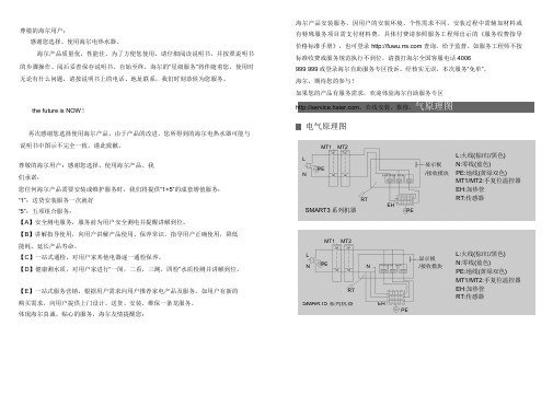
气原理图电气原理图MT1 MT2LL:火线(棕/红/黑色)显示板N:零线(蓝色) PEN /接收模块PE:地线(黄绿双色)MT1/MT2:手复位温控器EH:加热管RTEHRT:传感器SMART3系列机器PEMT1 MT2L显示板L:火线(棕/红/黑色)PE N N:零线(蓝色) N /接收模块PE:地线(黄绿双色)MT1/MT2:手复位温控器RT EH:加热管RT:传感器SMART5系列机器EHPE用户须知目录有害物质含量表产品中有毒有害物质的名称及含量表部件名称有害物质*明细表中的部件为不同型号产铅汞镉六价铬多溴联苯多溴二苯醚(Pb)(Hg)(Cd)(Cr(Ⅵ)) (PBB) (PBDE) 品所包含的主要部件的汇总,外壳及其组件○○○○○○本产品是否包含该部件,以产品的实际配置为准。
Smart型号产品使用指南说明书

Smart. Clear. Connected. Manual Cleaning InsightsOnline Dashboard (sample screens)Enlarged section showing a cleaning and disinfection process reportCapture what you’ve been missingIt’s smart. Manual cleaning is vital to your plant’s food safety and quality, but not knowing which parameters to measure or verify can expose your plant to production delays, recalls or worse. It’s clear. Ecolab Manual Cleaning Insights (MCI) digitally tracks and measures manual cleaning activities to provide straightforward insights that ensure controlled, dependable results.You’re connected. You have simple access to data and insights that prove compliance of critical parameters, improve efficiency and verify results. Smart. Clear. Connected.Make sure it’s clean from start to finish. Ecolab MCI gives you 24/7 visibility into the cleaning and sanitizing process, helping you:V erify cleaning and disinfection activitiesS ave money by reducing re-cleaning to promote on-time production startsI mprove efficiency by identifying suboptimal resource usageS ave time by standardizing and verifying proceduresEnsure your hygiene controls and prerequisite program are compliant with regulatory requirements and GFSI audit schemes.How MCI works to verify your cleaning process3SensorsSensors on cleaning stations capture critical data, including water temperature, air and water pressure and chemistry flow.1MCI ControllerMain and remote controllers gather and transmit the sensors’ data.Ecolab Proprietary2Microsoft Azure Cloud Encrypted data is securely transmitted, stored and analyzed to enable MCI to provide you with actionable insights.MCI does not require access to your internal network.Cellular Network MCI Online DashboardData on critical cleaning and sanitation activities is readily available to help you monitor and optimize resource use and activity duration in your cleaning process.Ecolab Proprietary4Better cleaning insights mean better cleaning outcomesFood safety and brand reputation•M aintain food quality and integrity with verifiable cleaning processesthat help prevent microbiological and chemical contamination•E nable correlation of cleaning and disinfection data to food safetyand quality issues to improve product shelf life and reduce recalled orscrapped productProductivity•M onitors and verifies phases in the cleaning process to reducerecleans and increase on-time production starts•I mproves efficiency by providing data that lets you identify trainingopportunities and ensure your team’s timely completion of tasksResource optimization and data capture•M onitors resource usage and compares it to benchmarks to help avoidunder- or over-usage and optimize total cost of operations• A utomatically captures, stores and analyzes data to improve insights,identify root causes and reduce time needed to prepare data for auditsSustainability• Sets limits and exceptions to help reduce water consumption, energycosts, optimize the cleaning process and preserve equipment asset life• Helps reduce food scrapping and waste• Helps minimize burden on effluent by optimizing chemistry usagePartner with Ecolab to solve your toughest manual cleaning challenges. Our completeprogram delivers peace of mind by combining powerful chemistry with smart technology and world-class service. Visit /MCI.©2022 Ecolab Inc. All rights reserved. 57926/0300/1021。
smart positionerip8001定位器操作说明书

smart positionerip8001定位器操作说明书1.接通气源,检查减压阀后压力是否符合执行器的铭牌参数要求(定位器的最大供气压力为7BAR,但实际供气压力必须参考执行器所容许的最大气源压力)。
2.接通4---20mA输入信号。
(定位器的工作电源取自输入信号,由DCS 二线制供电,不能将DC24V直接加至定位器,否则有可能损坏定位器电路)。
3.检查位置返馈杆的安装角度(如定位器与执行器整体供货,则已经由执行器供货商安装调试完毕,只需作检查确认,该步并非必须):按住MODE键。
并同时点击⇧或⇩键,直到操作模式代码1.3显示出来。
松开MODE键。
使用⇧或⇩键操作,使执行器分别运行到两个终端位置,记录两终端角度两个角度应符合下列推荐角度范围(最小角位移20度,无需严格对称)直行程应用范围在-28º--- +28º之内。
角行程应用范围在-57º---+57º之内。
全行程角度应不小于25º4.切换至参数配置菜单同时按住⇧和⇩键点击ENTER键等待3秒钟,计数器从3计数到0 松开⇧和⇩键程序自动进入P1.0配置菜单。
5.使用⇧和⇩键选择定位器安装形式为直行程或角行程。
角行程安装形式:定位器没有返馈杆,其返馈轴与执行器角位移输出轴同轴心一般角位移为90º直行程安装形式:定位器必须通过返馈杆驱动定位器的转动轴,一般定位器的返馈杆角位移小于60º, 用于驱动直行程阀门气动执行器。
注意:进行自动调整之前,请确认实际安装形式是否与定位器菜单所选形式相符,因为自动调整过程中定位器对执行器行程终端的定义方法不同,且线性化校正数据库不同,易卖工控可能导致较大的非线性误差。
6.启动自动调整程序(执行器或阀门安装于系统后最好通过此程序重新整定):按住MODE键点击⇧键一次或多次,直到显示出“P1.1”松开MODE键。
SOMFY 电动窗帘控制接口II 操作说明书

UNIVERSAL RTS INTERFACE IIOperating InstructionsThe addressable Universal RTS Interface II (URTSI II) can be used to communicate between home automation or other third party systems and SOMFY’s RTS Motors and controls. It is capable of individual or group control, and can be operated via infrared remote, RS232 and RS485 serial communication. Once an input is activated, an RTS radio command is sent to the automated window treatment.DESCRIPTIONCONNECTION DIAGRAMBack of Interface control boxIR Signal Common +5V DCIR Sensor Modular Pin-Out(Shown Tab-side Down)Part Number: 1810872N/CFCC INFORMATIONThis device complies with Part 15 of the FCC Results. Operation is subject to the following two conditions: 1. This device may not cause harmful interference, and2. This device must accept any interference received, including that which may cause undesired operation.NOTE: This equipment has been tested and found to comply with the limits for CLASS B digital device, pursuant to Part 15 of FCC Rules. These limits are designed to provide reasonable protection against harmful interference when the equipment is operated in a commercial environment. This equipment generates, uses and can radiate radio frequency energy and , if not installed and used in accordance with the instructions, may cause harmful interference to radio communications. However, there is no guarantee that interference will not occur in a particular installation. If this equipment does cause harmful interference to radio or television reception, which can be determined by turning the equipment off and on, the user is encouraged to try to correct the interference by one or more of the following measures:1. Reorient or relocate the receiving antenna2. Increase the separation between the equipment and receiver3. Connect the equipment into an outlet on a circuit different from that to which receiver is connected4. Consult the dealer or experienced radio/TV technician for help.WARNINGChanges or modifications not expressly approved by the manufacturer could void the user’s authority to operate the equipment.* As an option, power to the URTSI II can besupplied on leads 4 & 5. In this case, the plug-in transformer is not needed. In addition, the power can be daisy-chained to the next URTSI II over the CAT5 cable. The power supply should be sized based on the number of Interfaces on the network segment.A. INITIAL SETUP1. Connect a 9v DC transformer (included) to the receptacle on the back of the control box. The LED will light green to indicate power.2. Be careful not to mount or enclose Interface on or in metal, as this may effect radio reception.3. Set the RTS Receiver or motor into its Programming Mode. Refer to the installation instructions of the relevant RTS receiver or motor for this procedure. NOTE: for initial programming provide power only to the motor or control being programmed.4. Using the rotary switch, select the channel to be programmed. Letters A through F stand for channels 10 through 15, 0 for 16. Briefly press the programming button (1 sec. max), the window treatment will jog to indicate the channel has been memorized.5. Repeat the steps above for each channel or product to be memorized, up to 16. 6. To test the control operation, simply press the UP , STOP or DOWN buttons on the front of the control. The window treatment should move appropriately. The LED will flash red to indicate the radio signal has been transmitted.B. INFRARED OPERATION1. The RTS Interface is compatible with Somfy’s multichannel transmitter. Connect an infrared sensor to the appropriate connector on the back of the Interface.2. Each individual motor is activated by first aiming the transmitter at the sensor and pressing the desired unit number on the transmitter and then pressing the UP or DOWN buttons. Press the center button to STOP the window treatment at any time.3. The Infrared Channel stays active for 3 minutes. After that, the channel must be reselected.C. RS232 OPERATION1. The Somfy RS232 interface uses the following communications settings: 9600 Baud, 8 Data Bits, 1 Stop Bit, No Parity2. Set the rotary switch to position 1.3. T he basic format for communication is as follows: URTSI ADDR MOTOR CHAN DIRThe URTSI II address is 01.The motor channel should be 2 digits from 01 to 16. The directional commands are:U = Up D = Down S = Stop (Must be Capital letters)4. Examples:Motor 1 UP:0101U Motor 5 DOWN:0105D Motor 12 STOP:0112SD. RS485 OPERATION1. The Somfy RS485 interface uses the following communications settings: 9600 Baud, 8 Data Bits, 1 Stop Bit, No Parity2. With RS485, it is possible to connect 16 Universal RTS Interfaces on one network. Each Interface will have its own address. To select the address, set the rotary switch to the desired number. Letters A through F stand for addresses 10 through 15, 0 for 16.3. The basic format for communication is as follows: URTSI ADDR MOTOR CHAN DIR The URTSI II address should be 2 digits from 01 to 16. The motor channel should be 2 digits from 01 to 16. The directional commands are:U = Up D = Down S = Stop (Must be Capital letters)4. Examples:URTSI 1, Motor 1 UP:0101U URTSI 3, Motor 12 DOWN:0312D URTSI 14, Motor 9 STOP:1409S URTSI 10, Motor 15 UP:1015UOPERATIONMECHANICAL SPECIFICATIONS3 Overall Dimensions: L: 3 in. W:4 in. D: 1 /8 in.Typical Range (Optimal Conditions): 65 ft.ELECTRICAL SPECIFICATIONSPower: 9 - 15 V DC, 200mA20mA draw for each Universal InterfaceFrequency: 433.42 MhzDescriptionU niversal RTS Interface IIMultiChannel Infrared Transmitter IR SensorORDERING INFORMATIONPart Number181087218104989015078Description DB9 to RJ45 Adapter for RS232DB9 to RJ45 Adapter for RS485Part Number90150289015029Ref. No. 2500872ASOMFY SYSTEMS, INC. 10/08C SOMFY SYSTEMS, INC.47 Commerce Drive Cranbury, NJ 08512SOMFY CANADA6315 Shawson Drive, Unit #1Mississauga, Ontario L5T1J2SOMFY SYSTEMS, INC. reserves the right to change, update or improve this document without prior notice.。
- 1、下载文档前请自行甄别文档内容的完整性,平台不提供额外的编辑、内容补充、找答案等附加服务。
- 2、"仅部分预览"的文档,不可在线预览部分如存在完整性等问题,可反馈申请退款(可完整预览的文档不适用该条件!)。
- 3、如文档侵犯您的权益,请联系客服反馈,我们会尽快为您处理(人工客服工作时间:9:00-18:30)。
Ⅳ. 用户管理
11
联动功能 本设备具有辅助输入功能,设备接收联动信号后,会根据联动设置中设置的联动操作类型,
执行相应的联动操作。(注:关于解除联动的操作方法,参见附录 2 解除联动。) 1、在门禁设置界面,点击[ 联动设置 ]菜单,进入联动设置界面,默认联动设置为“无”。
如图 4 所示。如需修改,点击[ 联动设置 ],进入修改界面,如图 5 所示。 2、点击选中联动操作类型,然后按 键返回上一界面。 控锁继电器:设备接收联动信号后,触发电锁常开。 报警继电器:设备接收联动信号后,触发报警器报警。 锁和报警继电器:设备接收联动信号后,触发电锁常开,并同时触发报警器报警。 注:关于解除联动的操作方法,参见附录 2 解除联动。
16
以下配件在本文档中提及,但不包括在标准配置中。
组件名
图片
组件名
电脑
门锁
门磁 报警器
出门开关 485 转换器
门禁控制器
网络连接线
门铃
17
图片
附录 2 解除联动
解除联动 设备接收到辅助输入信号后,触发联动动作,此时设备待机界面提示“联动功能启动”。 在屏幕上按 进入主菜单界面,界面提示“是否解除联动?”,按确认,即可解除联动。 注意事项 1、解除报警的前提: (1)没有拆机事件。 (2)门磁已复位。 否则管理员解除联动,并退出主菜单后,设备将继续报警。 2、如果设备设置了常开常闭功能,执行解除联动操作时,存在以下两种情况: (1)当门设置为“常开”时,若在常开时段,则解除联动后门继续常开,只解除报警;若不在常开时段,则关门并解除报警。 (2)当门设置为“常闭”时,解除联动后门将关闭,并解除报警。
查找用户
1、在用户管理界面,点击[ 查找用户 ]菜单,进入如图 9 所示界面。
2、输入工号。(备注:输入错误时,可按[
]键删除或按[ C ]键清除错误输入。)
3、输入工号后,按[ OK ]键,查找该工号对应的用户,如图 10 所示。
12
编辑用户 编辑和删除已登记用户。(注:在查找用户界面,按[ 编辑用户 ] 进入编辑用户界面,具体操作方 法同新增用户一致。
在主菜单界面按[ 门禁设置 ]图标,进入门禁设置界面(如图 3 所示):
时间段设置:为设备添加门禁时间段,设备按照已设置的时间段控制设备门禁。 节假日设置:新增门禁节假日,并设置该节假日使用的门禁时间段。 门禁组设置:设置在某个特定时间段或时间段的组合,用户可以通过验证打开门。(注:可以验 证打开门的用户组合,需要在用户门禁设置中设置。) 开锁组合设置:为设备添加开锁组合,并设置该组合使用的门禁组的开门人数。(注:各门禁组 开门人员的总数必须小于或等于 5。) 门禁管理参数:设置设备的锁驱动时长(秒)、门磁延时(秒)、门磁开关类型(常开、常闭或 无)、门磁报警延时(秒)、错按报警次数(次)、常闭/常开时间段、节假日是否有效。 胁迫报警参数:设置发生胁迫报警时的报警延迟时间(秒)。 反潜设置:设置设备的反潜功能。 恢复所有门禁设置:将所有门禁设置恢复到出厂状态,清恢复成功后,将自动重启设备。
韦根功能
本设备提供标准的 Wiegand 26 输出,可以作为读头使用。设 备到控制器的连接线的距离以不超过 15 米为宜。(如需要更远的传 输距离或周围干扰强的地方,可采用 Wiegand 信号延长器)
注意:不论指纹读头是否从门禁控制器供电,都必须确保它和 门禁控制器共地,以保证 Wiegand 传输稳定。(详见图 6)
密码验证 1、在初始界面,按 键进入输入工号界面,输入需密码验证的工号(工号输入方法,参见查找 用户操作),如图 15 所示。 2、按[ OK ]键确认,并进入输入密码界面。
3、输入正确密码(密码输入方法,同工号输入方法一致),如图 16 所示。 4、按[ OK ]键确认,密码验证通过后,如图 17 所示。
在主菜单界面按 [ 系统设置 ]图标,进入系统设置界面(如图 2 所示):
Ⅲ. 门禁设置
系统参数:设置 1:1 匹配阀值、1:N 匹配阀值、时间格式、是否开启键盘语音、设备进入定 时休眠的时间。 系统信息:查看记录容量和设备信息。 时间日期:设置设备的时间和日期。 启用签到状态:设置是否启用签到状态、定时状态转换功能、各考勤状态的自动转换时间。 自动检测:TFT 屏幕测试、语音测试、采集器测试、实时时钟测试。 恢复全部出厂设置:将设备内的参数设置全部恢复为出厂设置。(注:恢复设置时不会清除 设备中的人员信息和验证记录。)
15
附录 1 安装注意事项
1、安装前和安装过程中,请确保已关闭电源系统。带电操作,可能损坏设备的核心部件。 2、所有接线端子的裸露部分不得超过 5mm,以防过长的裸线意外的接触,导致设备的损坏,同时要求您使用不同颜色的连接线。 3、在静电非常严重的地方或者冬季,请先连接地线,再进行其他接线的安装,以防止过大的瞬间静电损坏设备。 4、请先连接好其他连线后再连接电源线,如果发现设备不能正常运行,请先断掉电源总开关,再进行必要检查。谨记:一切带电 的接线将会意外损坏设备,我们将不对该类操作导致的损坏进行正常的保修。 5、设备安装的高度推荐为 1.4~1.5 米。 6、完成设备安装后,在使用设备之前,请先撕掉指纹采集器上的保护膜。 7、请在门外有人时测试出门开关;因为有时意外的问题可能导致您无法正常出门调试。 8、为了保障设备长期稳定运行,我们在出厂前设置了自动休眠及唤醒功能,请仔细检查该功能在投用前的正常设置。 9、本设备额定工作电压为 DC 12V,额定电流为 300mA。如电源没有达到以上要求,可能导致无法正常驱动电锁甚至损坏设备。 10、对设备进行接线时,请阅读并严格遵照本文中的说明进行接线。因异常接线导致核心板烧坏,指纹头烧坏所引起的设备不启 动,均不属于保修范围。 11、若电源与设备之间间距比较长,请勿使用网线或其他种类的线代替电源线。选择电源线时,应要考虑到传输距离过长造成电 压衰减。 12、使用 485 组网时,请使用专业 485 线和有源的 RS232/485 转换器,采用总线结构方式布线。在 RS485 通信距离超过 100 米的情况下,在 RS485 总线的起点终端设备上和末尾终端设备上加上终端匹配电阻,阻值约为 120Ω。
9
6. 安装注意事项
16
7. 解除联动
18
包装组件清单
门禁机 1台
螺丝刀 1/把
用于固定设备
快速恢复二极管 1/个
螺丝 1个 用于固定设备
1
膨胀螺栓/螺丝 4 个/4 个
用于固定后壳
光盘 1/个
操作面板概览
2
系统结构
设备与电脑通过 TCP/IP 直连
设备与电脑通过 RS485 组网
设备与电脑通过 TCP/IP 组网 系统安装示意图
ⅳ.复位键和防拆开关
由于误操作或其他意外故障,导致设备无法正常工 作时,通过本复位键可以重新启动设备。
1、找一个直径小于 2mm 的顶部尖锐的工具。 2、在设备的底端找到 Reset 标志及小孔,如图 8 所示。 3、将此工具插入小孔中,如图 8 箭头方向插入一下,然 后拔出,即可将设备复位。
防拆开关位于设备背面。当设备被拆除时,通过端
Ⅵ. 数据管理 Ⅶ. U 盘管理
在主菜单界面点击[ 数据管理 ]菜单,进入数据管理界面(如图 18 所示):
删除记录:删除设备中的所有记录。 删除全部数据:删除设备中的所有考勤记录、用户信息和门禁设置。 清除管理权限:清除所有用户的管理权限,即将设备中所有用户的权限设置为“普通用户”。
在主菜单界面点击 [ U 盘管理 ]菜单,进入 U 盘管理界面(如图 19 所示):
注意:为了防止锁生锈,请做好锁的防雨措施。 电锁的接法:本设备可以同时支持“常开型”和“常闭型”门锁;根据需要分别连结在不同的端子上既可。对通电时打开、 断电时关闭的锁,应该使用 NO(常开)端子;对通电时关闭、断电时打开的锁,应该使用 NC(常闭)端子。 锁与设备共用电源的方法,如图 1,2 所示:
在主菜单界面按 [ 用户管理 ]图标,进入用户管理界面(如图 6 所示):
新增用户:输入工号(最大长度为 9 位)和密码(最大长度为 6 位),设置用户权限(普通用户 或管理员);登记 ID 卡。 查找用户:输入工号,按[ OK ]键查找该工号对应的用户,并进行编辑、删除和设置用户门禁。 记录查询:输入工号和月份,点击[ 开始查询 ]查询该工号对应的用户在设置的月份的所有验 证记录。
连接电源:如图 7 所示。
7
ⅲ.安装后的检查
在给设备供电前,请检查是否正确安装设备,并检查锁驱动和其他外围设备是否正常工作。 1、设备供电之后 LED 的绿灯开始闪烁。 2、推荐进入主菜单 系统设置 自动检测 进行检测。 3、进入主菜单用户管理新增用户指纹登记,登记一枚指纹。通过指纹验证测试设备及门锁。 4、如果没有问题,请删除已登记的指纹。
2.8 寸易用型指纹门禁安装指南&入门指南
版本:1.0 日期:2014 年 05 月
由于产品不断更新,本公司不承诺实际产品与该数据一致,同时也不承担由于实际技术参 数与本数据不符而导致的任何争议,任何改动恕不提前通知。
目录
1. 包装组件清单
1
2. 操作面板概览
2
3. 系统结构
3
4. 设备安装
4
5. 快速入门指南
3
安装设备
ⅰ.安装设备
1.取下设备底部螺丝。
2.取下设备后壳。
3.使用螺丝将后壳固定在墙面上。
4.将设备固定到后壳上。
5.拧入固定螺丝。
4
ⅱ.连接外围设备
在接线前,应确保设备电源已断开,在通电状 态下接线可能会对设备造成严重的损坏。请按照下 面的介绍连接外围设备。
连接门磁 连接出门开关 连接报警器 连接门铃 连接门锁
14
下载考勤数据:将设备中的考勤数据下载到 U 盘中。 下载用户数据:将设备中的用户数据下载到 U 盘中。 上传用户数据:将 U 盘中的用户数据上传到设备中。 固件升级:通过 U 盘中的设备固件升级包,升级设备固件。
