EC Testr 11+ 盐分测试说明书(英文)
赛默飞水质分析仪手册

操作手册
Байду номын сангаас
Thermo Scientific
目录
前言 ....................................................................................................................................................... 6 安全和注意事项 ............................................................................................................................ 6 第一章 仪器基础信息 .................................................................................................................... 7 1.1 仪器组成 ............................................................................................................................ 7 1.1.1 接口 ........................................................................................................................ 7 1.1.2 键盘 ...................................
盐分测试笔使用说明书-090224mq翻译-ch审核
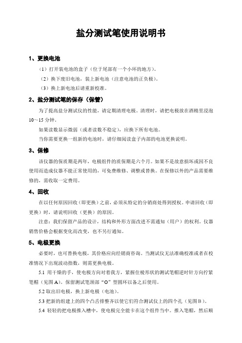
盐分测试笔使用说明书1、更换电池(1)打开装电池的盒子(位于尾部有一个小环的地方)。
(2)换下废旧电池,装上新电池(注意电池的正负极)。
(3)换上新电池后请重新校准。
2、盐分测试笔的保存(保管)为了提高盐分测试仪的性能,请定期清理电极。
清理时,请把电极放在酒精里浸泡10~15分钟。
如果读数显示微弱(或者读数不稳定),应换下所有电池。
当你需要更换一组新的电池时,请仔细阅读盒子内部的电池更换说明。
3、保修该仪器的保质期是两年,电极组件的质保期是六个月。
如果不是故意损坏或因不良使用而造成仪器不能正常使用的,可免费维修、调整或替换。
在保修以外的产品需要维修的,需收取一定费用。
4、回收在以任何原因回收(即更换)之前,必须从特定的分销商处得到授权。
申请回收(即更换)时,请说明回收(更换)的原因。
注意:我们保留产品的设计,结构和外形方面改进不需通知(用户)的权利。
仪器销售价格会根据变化而改变,也不另行通知。
5、电极更换必要时,也可替换电极,其价格应向经销商咨询。
当测试仪无法准确校准或者在校准情况下出现波动指数,则需更换电极。
5.1用干燥的手,使电极方向对着我方,紧握住棱形状的测试笔帽逆时针方向拧紧笔帽(见图A)。
保留测试笔颈部“O”型圆环以备之后使用。
5.2取出旧电极,换上新电极(电池)。
5.3把新的组建上的四个凸舌排整齐以使它们符合测试仪上的四个孔(见图B)。
5.4轻轻的把电极推入槽中,使电极完全能卡在这个组件当中。
推入笔帽,然后顺时针拧紧。
6、推动按钮校准校准后,可得到迅速、稳定、可重复的读数。
7、运用范围水质测试:水和盐分处理、水力发电试验、蒸发器(热水器,锅炉)。
工厂:生态研究以及更多的运用范围。
规格(安全部翻译 2009年)。
NBI 水质 EC(电导率)传感器 用户手册说明书
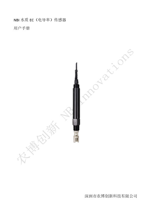
NBI水质EC(电导率)传感器用户手册深圳市农博创新科技有限公司使用前须知•使用前请仔细阅读本说明书,因不遵守本说明书的操作规程及注意事项而造成产品损坏或失效的,农博创新将视情况不提供保修服务。
•使用前请检查包装是否完好,若发现产品有损坏,请将损坏货品与包装物一并寄回农博创新。
•因产品功能、性能的持续改进和优化,如有参数变动,恕不另行通知。
1.概述1.1功能及应用介绍农博创新水质EC传感器是一款用于水质电导率实时监测的传感器,可准确测量微生物、鱼虾类、水草类、泥沙等多种环境下淡水或海水水体的电导率。
配合农博创新Watcher Pro••1.2.2尺寸1.2.3各部位说明传感器接头探头保护帽2.使用方法2.1安装方式水质EC传感器采用沉入式安装,详细的信息请参见Watcher Pro2(Aqua)无线水质监测产品用户手册。
3.维护3.1贮存水质EC传感器使用完毕后需要长时间贮存时,应先将水质EC传感器冲洗干净,然后插入加有保护溶液的保护帽,或者可将水质EC传感器浸没到保护溶液中。
同时应避免传感器探头4.注意事项1请勿将传感器置于水流较快的地方,会导致污染物堆积过快6.联系我们深圳市农博创新科技有限公司地址:中国广东省深圳市南山区讯美科技广场2座7楼709官网:联系电话:400-015-1568邮箱:**********************保修条例1.本产品保修期为半年。
从发货之日起六个月内,本产品保修期内按说明书正常使用的状况下产生的故障,予以免费维修。
2.属于以下情况之一不属于免费保修范围,农博创新提供有偿服务,敬请留意:(1)超过保修有效期;(2)未按产品说明书的要求使用、安装而造成的损坏;(3)由非农博创新授权维修服务者拆修造成的损坏;(4)因用户使用不当而造成的产品损坏,如摔坏、机械破坏等;(5)因不可抗力(如火灾、地震、台风等)造成的损坏;(6)其他非产品本身设计、技术、制造、质量等问题而导致的故障或损坏。
Testomat ECO中文说明书(简版)

LV2 报警值
监测中指示灯
1. 灯信号呈红色,显示测定值超过报警点,继电器正在动作;呈绿色则解除,即低于报警点。 2.测定值 当测定值低于测量范围下限,则显示如:M1:<0.89 ppm。 当测定值高于测量范围上限,则显示如:M1:>8.93 ppm。 3.报警点的数值分别显示于最下面一行,可以修改。 4.故障信息(红灯)及正在进行监测的灯信号: 同时功能故障的指示会出现在屏幕上,想要消除灯信号,唯有更正故障的功能后,再按下手动 解除报警按钮,才能恢复。
三、基本操作步骤及注意事项:
1.进入“M”所有设定的参数进行修改的入口。 2.进入“M”以后,可以由箭号按键来选择要设定的参数来进行修改,被选定的功能,字体会明显 变大,按 ENTER 键,则“*”星型记号就会停留,表示设定完成。再按 M 键跳出,回到主显示 屏,仪器就会自动开始。 3.Testomat ECO 功能设计因应各种不同需求,因此相当庞大,用户可参考原厂操作说明,作最 佳的应用。 以下仅就基本功能略述其使用方法,其余功能可以此类推。 注意事项: 检查所有管路是否漏水。特别注意,测试水进水是否畅通。 前置水压调节阀是否恰当。 (1)设定参数的步骤,必须在 M 功能下,方可执行。 (2)为避免不当的加药,请进入手动 STANDBY 状态。纠正完毕,请回复至自动 Auto。 (3)注意温度是否过高,影响仪器正常操作。
100flushflashchamberdrainchamberfillchambergermanenglishfrenchitalian保养维护程序选择剂量冲洗冲洗测量槽手动操作语言选择自我诊断功能排水填充测量槽德语英语法语意大利语错误信息故障排除ffdosingpump剂量泵功能错误cancelwithhornkey用喇叭键取消检查计量泵的线是否正确连接mfturbid测量错误混浊cancelwithhornkey水太混浊太脏measuringrangeexceeded超出测量范围更换其他型号试剂lowwaterpressure低水压cancelwithhornkey进行调整ffoutlettodrain排放功能错误cancelwithhornkey即使led流出灯out水仍然在测量槽内更换阀reagentlow试剂不足cancelwithhornkey检查试剂高度如果需要的话更换试剂mfdirtiness测量错误
水抗挥发性盐度测试笔规格及操作说明书
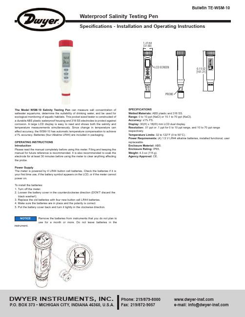
Specifications - Installation and Operating InstructionsBulletin TE-WSM-10- C or F is the unit of the liquid temperature.- is the battery low icon.KeypadOperation1. Remove the probe cover from the meter to expose the electrode.2. Press to power on the meter. The LCD will display parameters (ex: tnr, tCo, tds,rAn) in turns and then it will enter normal display.accuracy. Alternatively, you can manually select the ranges. For example, if you prefer the meter to display a reading such as .50 mS instead of 500 uS, you press for more than 2 seconds.measurement mode. When the reading is stable, the unit will stop flashing.10. Press to freeze current readings. The text “Hold” will appear on the LCD. Pressagain to release.11. Turn off the meter by pressing .12. Make sure your electrode is clean and store it carefully. Before storage, rinse itcarefully in de-ionized water and store dry with the cap. Remember the storage temperature limits. For more information, see the maintenance section.13. Air bubbles can easily adhere around the gap between the electrode and theTo disable the auto power off:Before power on, press + simultaneously until an “n” appears on the screen. Then, release the keys to return to normal mode.The advanced setup mode lets you customize your meter’s preferences and defaults. To change the parameters, you can press for more than 2 seconds. You will enter setup mode when the meter is in measurement mode.1. When the meter is in measurement mode, press f for more than 2 seconds toenter setup mode.2. Press , , or to select P1.0.3. Press momentarily again to enter unit setting.4. Press or to select C or F.5. Press momentarily to confirm the unit, or press it for more than 2 seconds toreturn to P1.0 without saving.6. While in P1.0, press for more than 2 seconds to return to measurement mode. P3.0 Reset Meter (rSt)When you decide to reset the meter, all parameters will be reset to factory default values, including the calibration information.1. In P3.0, press momentarily to enter P3.1.2. Press or to select Y or N.3. Press momentarily to confirm the state and return to P3.0, or press it for morethan 2 seconds to return to P3.0 without confirming the P3.1 value.P4.0 Review Calibration Information (CAL)In P3.0, press or to select P4.0.P4.1 Range 1 Calibration Informationpress momentarilyconcentration. If the meter is not yet calibrated, “---”will display on the LCD.In P4.1 or P4.2, press momentarily to confirm the state and return to P4.0. In P1.0, P2.0, P3.0, P4.0, you can press for more than 2 seconds to return to1. Turn off the meter and stay in normal measurement mode.2. Press or for more than 2 seconds to select the range.(Default)temperature.7. Press for more than 2 seconds to begin the calibration. The SALT value willblink on the LCD.8. Press the or to adjust the value to match the value to the calibrationstandard. You can adjust the SALT reading up to ±30% from the detected value.9. When the “CAL” stops blinking, you can press to confirm the value. The meterwill switch back to SALT measurement mode. If “CAL” always blinks, check theThe text P1.1, P1.2, P1.3, P2.1, P3.1 will not displayLCD.NOTICE。
EC TDS SALT 检测器 说明书
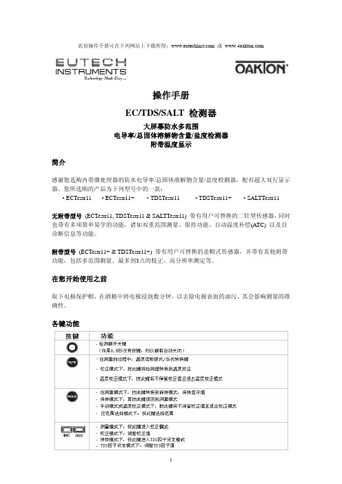
此份操作手册可在下列网站上下载所得: 或 操作手册EC/TDS/SALT 检测器大屏幕防水多范围电导率/总固体溶解物含量/盐度检测器附带温度显示简介感谢您选购内带微处理器的防水电导率/总固体溶解物含量/盐度检测器,配有超大双行显示器。
您所选购的产品为下列型号中的一款:• ECTestr11 • ECTestr11+ • TDSTestr11 • TDSTestr11+ • SALTTestr11无附带型号 (ECTestr11, TDSTestr11 & SALTTestr11) 带有用户可替换的二针型传感器,同时也带有多项简单易学的功能,诸如双重范围测量、保持功能、自动温度补偿(ATC) 以及自诊断信息等功能。
附带型号 (ECTestr11+ & TDSTestr11+) 带有用户可替换的盖帽式传感器,并带有其他附带功能,包括多范围测量、最多到3点的校正、高分辨率测定等。
在您开始使用之前取下电极保护帽,在酒精中将电极浸泡数分钟,以去除电极表面的油污,其会影响测量的准确性。
各键功能注释:INC和DEC键位于电池盒内。
参见图1注释:对于ECTestr11 & ECTestr11+型号的仪器,其HOLD键上面写的是“HOLD/ENT”开机按ON/OFF键打开检测器。
液晶显示器上将显示如图2所示的开机流程。
开机后如果您8.5秒没有按任何键,仪器将自动关闭来保存电池。
选择范围根据您选择的产品,您可以把检测器的读书限定在一个特别的测量分为 (PU, LO或HI),或者满量程 (AUTO)。
默认值为AUTO。
如果您设定的范围为非AUTO,则检测器在校正过程中只能使用所设定的特别范围。
如果您所测样品的电导率/TDS大于所设定的测量范围,则LCD上会显示“OR”的错误信息。
各型号的测量范围参见样品型号一章。
范围选择步骤:1.关闭检测器。
按住°C/°F键不放,然后用ON/OFF键打开检测器。
Sun Electronic Systems EC11环境测试室说明书
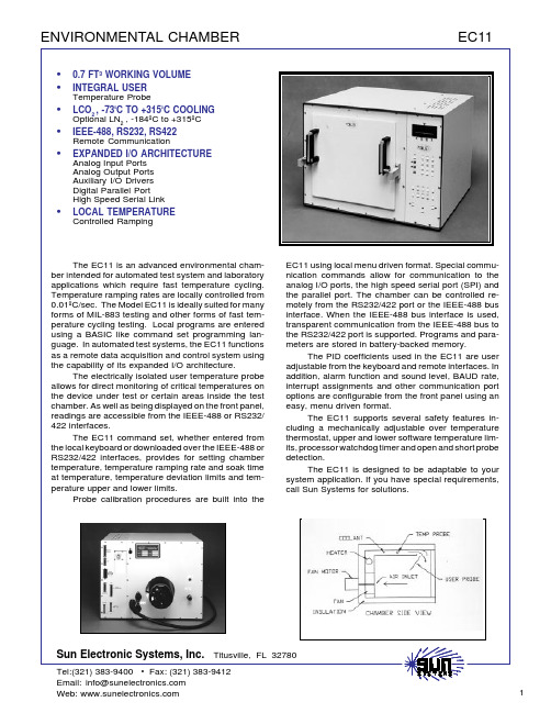
•0.7 FT³ WORKING VOLUME•INTEGRAL USER Temperature Probe•LCO 2 , -73ºC TO +315ºC COOLING Optional LN2 , -184ºC to +315ºC•IEEE-488, RS232, RS422Remote Communication•EXPANDED I/O ARCHITECTURE Analog Input Ports Analog Output Ports Auxiliary I/O Drivers Digital Parallel Port High Speed Serial Link•LOCAL TEMPERATURE Controlled RampingThe EC11 is an advanced environmental cham-ber intended for automated test system and laboratory applications which require fast temperature cycling.Temperature ramping rates are locally controlled from 0.01ºC/sec. The Model EC11 is ideally suited for many forms of MIL-883 testing and other forms of fast tem-perature cycling testing. Local programs are entered using a BASIC like command set programming lan-guage. In automated test systems, the EC11 functions as a remote data acquisition and control system usingthe capability of its expanded I/O architecture.The electrically isolated user temperature probe allows for direct monitoring of critical temperatures on the device under test or certain areas inside the test chamber. As well as being displayed on the front panel,readings are accessible from the IEEE-488 or RS232/422 interfaces.The EC11 command set, whether entered from the local keyboard or downloaded over the IEEE-488 or RS232/422 interfaces, provides for setting chamber temperature, temperature ramping rate and soak timeat temperature, temperature deviation limits and tem-perature upper and lower limits.Probe calibration procedures are built into theEC11 using local menu driven format. Special commu-nication commands allow for communication to the analog I/O ports, the high speed serial port (SPI) and the parallel port. The chamber can be controlled re-motely from the RS232/422 port or the IEEE-488 bus interface. When the IEEE-488 bus interface is used,transparent communication from the IEEE-488 bus to the RS232/422 port is supported. Programs and para-meters are stored in battery-backed memory.The PID coefficients used in the EC11 are useradjustable from the keyboard and remote interfaces. In addition, alarm function and sound level, BAUD rate,interrupt assignments and other communication port options are configurable from the front panel using an easy, menu driven format.The EC11 supports several safety features in-cluding a mechanically adjustable over temperaturethermostat, upper and lower software temperature lim-its, processor watchdog timer and open and short probe detection.The EC11 is designed to be adaptable to your system application. If you have special requirements,call Sun Systems for solutions.LOCAL AND REMOTE CONTROL INTERFACESThe EC11 supports stand-alone operation with a full function keyboard, a 2-line LCD and a powerful programming language. For automated test systems, a complete talker/listener IEEE-488 interface is available with serial and parallel poll capability. For remote operation over long distances, RS232 and RS422 serial interfaces areChart Recorder。
安德森仪器公司IR-11 折射计 使用说明书
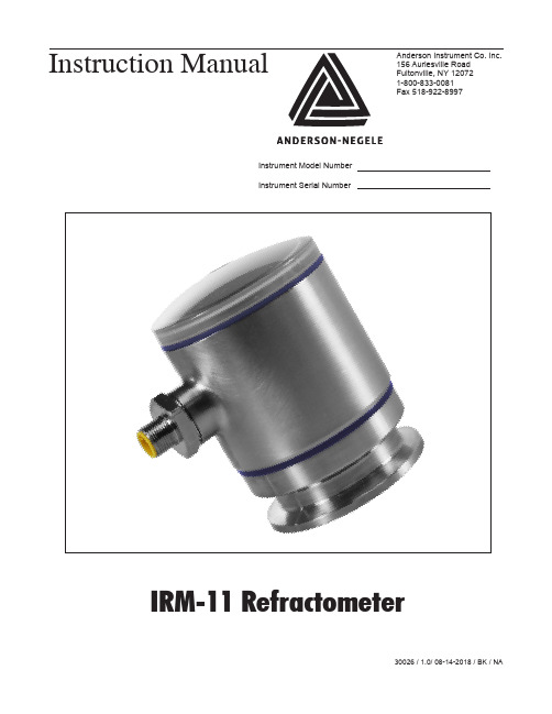
These safety instructions have to be strictly observed in order:
• To not endanger the safety of persons and environment
• To avoid any damages to the measuring instrument
Electrical connection
Cable gland M16 x 1.5
Cable connection
M12 connector
Supply voltage
5…24 V DC max. 150 mA
Protection class
IP69K
Weight
480 g (1 lbs)
PAGE 5
Temperature ranges
Ambient
-10…60 °C (14...140 °F)
Process
20...100 C (-4...212 F) compensated range
CIP/SIP
Up to 140 °C (284 °F) max. 60 min
Process pressure
• To prevent any faulty product as a result of use
The electric connection may only be carried out by qualified persons who have the necessary electrical knowledge and have been authorized by the owner to do so. The wiring of the voltage supply and the output has to be carried out professionally in consideration of current electrical design and regulation. Also refer to chapter 3 “Installation”/”Electrical” for more information.
TRIZMA 预设晶体盐产品说明书

TRIZMA® Pre-set crystals Cell Culture Tested Product Number T 1069 Store at Room TemperatureProduct DescriptionThis product is cell culture tested (1.82 mg/ml) and is designated as Biotechnology Performance Certified. It has been tested for endotoxin levels and analyzed for the absence of nucleases and proteases.This product is a pre-mixed combination of TRIZMA base and TRIZMA HCl in convenient foil pouches. When dissolved in 1 L of deionized water, this product gives a 0.1 M TRIZMA solution with a pH of 8.3 at25 °C. TRIZMA is the registered trademark fortris(hydroxymethyl) aminomethane, commonly called Tris.Sigma Technical Bulletin 106B contains additional information on temperature and concentration effects, and on the use of pH electrodes with TRIZMA buffers. Tris is an established basimetric standard and buffer used in biochemistry and molecular biology.1 It may be used by itself as a buffer or as a component of mixed buffer formulations.2 These different buffer formulations include:• Tris-EDTA (TE) buffer• Tris magnesium buffer• Tris-acetate-EDTA (TAE) buffer• Tris-borate-EDTA (TBE) buffer• Tris-buffered saline (TBS)• Tris-buffered saline with dextrose (TBS-D)• Tris-glycine buffer• Tris-phosphate EDTA buffer• Tris-SDS buffer• Tris-sucrose• Tris-Tricine-SDS bufferTris salts are used in protein crystallization at various pH values (Product Nos. 82009, 70437, 75403, 86684, 73513).3,4,5,6 The use of low-ionic strength Tris buffers in the formation of intermediate filaments of lamin from Caenorhabditis elegans has been described.7Tris has been utilized in studies of double stranded complexes of peptide nucleic acids (PNA) and their complementary DNA sequences, by use of anion exchange HPLC.8 The use of Tris in capillary electrochromatography and UV analysis of tocopherols and tocotrienols has been reported.9 Precautions and DisclaimerFor Laboratory Use Only. Not for drug, household or other uses.Preparation InstructionsThis product is soluble in water (666 mg/ml), yielding a clear, colorless solution.Storage/StabilityTRIZMA solutions can be autoclaved. Tris has a significant temperature coefficient:• From 5 °C to 25 °C, the pH decreases an average of 0.03 pH units per °C.• From 25 °C to 37 °C, the pH decreases an average of 0.025 pH units per °C.Thus it is necessary to choose the proper mixture to give the desired final pH at the desired temperature. The pH of 0.05 M solutions of this product at various temperatures is as follows:5 °C = pH 8.8825 °C = pH 8.3037 °C = pH 8.01References1. Gomori, G., Preparation of Buffers for Use inEnzyme Studies. Methods Enzymol., 1, 138-146(1955).2. Molecular Cloning: A Laboratory Manual, 3rd ed.,Sambrook, J. and Russell, D.W., CSHL Press(Cold Spring Harbor, NY: 2001), pp. 5.8, 5.30,5.43, 5.60, 5.76, 10.25-10.26, 12.75, 12.84, 12.87,13.52, 16.29-16.31, A1.2-1.3, A1.7-A1.8,A1.17-A1.18, A1.22, A8.42-A8.43.3. Brzozowski, A. M., et al., Structural analysis of achimeric bacterial α-amylase. High-resolutionanalysis of native and ligand complexes.Biochemistry, 39(31), 9099-9107 (2000).4. Knapp, S., et al., Crystallization and preliminarycrystallographic analysis of an amylopullulanasefrom the hyperthermophilic archaeon Pyrococcus woesei. Proteins, 23(4), 595-597 (1995).5. Andrykovitch, M., et al., Crystallization andpreliminary X-ray diffraction studies of NusG, aprotein shared by the transcription and translation machines. Acta Crystallogr. D Biol. Crystallogr.,58(Pt 12), 2157-2158 (2002).6. Campos, A., et al., Crystallization and preliminaryX-ray analysis of FlhD from Escherichia coli.J. Struct. Biol., 123(3), 269-271 (1998). 7. Karabinos, A., et al., The single nuclear lamin ofCaenorhabditis elegans forms in vitro stableintermediate filaments and paracrystals with areduced axial periodicity. J. Mol. Biol., 325(2),241-247 (2003).8. Lesignoli, E., et al., Recognition and stranddisplacement of DNA oligonucleotides by peptide nucleic acids (PNAs). High-performance ion-exchange chromatographic analysis.J. Chromatogr. A., 922(1-2), 177-185 (2001).9. Abidi, S. L., and Rennick, K. A., Capillaryelectrochromatographic evaluation of vitamin E-active oil constituents: tocopherols andtocotrienols. J. Chromatogr. A, 913(1-2), 379-386 (2001).TRIZMA is a registered trademark of Sigma-Aldrich Biotechnology.GCY/RXR 5/03Sigma brand products are sold through Sigma-Aldrich, Inc.Sigma-Aldrich, Inc. warrants that its products conform to the information contained in this and other Sigma-Aldrich publications. Purchaser must determine the suitability of the product(s) for their particular use. Additional terms and conditions may apply. Please see reverse side ofthe invoice or packing slip.。
盐密度测试仪使用说明

DBM-311智能盐密度测试仪Insulator Sault Density Tester使用说明书User's Manual 湖北电保姆电力自动化有限公司H ubei E-Nanny Electric Power Automation Co.,LTD手册说明尊敬的顾客,您好!首先衷心感谢您选购本公司的智能电导盐密测试仪产品。
为了帮助您尽快熟练使用仪器,请您务必详细阅读本使用说明书。
本手册主要介绍“DBM-311智能电导盐密测试仪”的使用方法,请您遵守并按规定使用本产品,以确保仪器安全良好运行。
请遵守国家电力工业的安全工器具预防性试验安全规程,勿在易燃、易爆、潮湿等恶劣环境下操作;仪器用外接电源供电时,请使用本仪器专用电源适配器接市电220V,在插拔电源时,应小心谨慎,避免触电;仪器用内置电池时,推荐使用6节5号1.5V干电池。
应避免新旧电池混用,并定期检查电池电量。
长期不使用仪器时,请卸下电池。
未经本公司许可,请勿拆卸该仪器。
本仪器内部设置非法拆机自毁程序,如因擅自拆卸仪器而导致仪器功能失效,则不予保修和退换。
本公司的服务宗旨是“为客户提供尽善尽美的服务”。
为保证产品功能不断改进和完善,本仪器规格可能不定期更新,因此您使用的仪器可能与说明书有些许差别,恕不另行通知。
如果您有疑问请致电本公司售后部,也可访问本公司网站了解更多信息。
目录一、概述 (3)1.1引言 (3)1.2仪器介绍 (3)1.3依据标准 (4)1.4术语解释 (4)二、产品信息 (4)2.1主要特点 (4)2.2供电方式(交直两用) (5)2.3操作界面 (5)2.4功能菜单(主菜单) (6)2.5技术指标 (6)三、供货范围 (7)四、功能描述 (7)4.1仪器设置 (7)4.2数据管理 (9)4.3参数设置 (10)4.4开始测试 (12)五、测试步骤 (12)5.1选取绝缘子 (12)5.2配置溶剂 (12)5.3擦试表面污秽 (13)5.4溶解 (13)5.5测试 (13)5.6打印 (13)六、维护保养 (13)6.1仪器保护 (13)6.2电极维护 (14)6.3电池维护 (14)6.4打印机维护 (14)七、售后服务 (14)八、附录 (15)一、概述1.1引言在电网系统中,电压等级高、输送容量大的变电站和输电线路起着十分重要的作用。
ECEFast TDS 110温度测量仪器说明书

1. How many measurements can be stored in the machine?Total up to 500 values. The memory has got 5 files and each file can store up to 100 values.2. How fast is the measurement?Four measurement readings per second3. Is there a RS 232 communication available?Not in this TDS 110 model. But there are models available to connect the meter to the thermal mini ‐printer4. Key functions: Old model/ New model / Hard copy Instruction manual in the softcopy manual that comes with the meter5. While setting up the probe frequency there are 4 options available. Which one should I choose? It depends on the probe you have purchased. At present ECEFast is selling 5M model only. Other models are available on request. 2M, 5M, 7M or ZW• Frequency 2MHz: High Penetration ‐10ºC to 60ºC; Diameter 14mm; measuring range 4.0 to 500mm • Frequency 5MHz : High temperature resistant ‐10ºC to 300ºC; Diameter 12mm; measuring range 4.0 to 80mm (steel) How to select the frequency in the meter? – Refer Answer 96. What is a coupling agent? Coupling agents or Couplant are used to help the ultrasonic wave to have better transmission coefficient and give better dB. Liquids like glass water, glycerine, engine oil, consistent grease can be used as a coupling agent. It is always good to contact the supplier to supply the correct coupling agent7. Why should I need sound velocity for the thickness gauge and why should the sound velocity value beaccurately entered in the meter? The speed of sound varies in various materials and the information is necessary to have when using our TDS 110 ultrasonic thickness gauge, as the speed the ultrasound will move through the material to obtain an accurate thickness reading.8. I can’t get the meter going? I think you mean, the meter is not reading the thickness of the material as you would expect the meter to do and it stays in the sound velocity mode. The meter is working alright. There are few more steps to go to the thickness measurement mode. Select the correct sound velocity from the table and value closer to that.For example choose or enter 5920m/s for steel or 2388m/s for PVC then apply the Couplant on the surface of the measuring material or on the surface of the sensor. Then you will see the reading below:FAQ on thickness gauge DH-TDS1109. What is zero calibration ? It is not mentioned in the soft copy but available in the section 3.5 of the printed copy that comes with the Instrument. i) Select the correct transducer frequency (5M)from the saved data the key the andWhen the probe is coupled with the material to be measured, the instrument will display the coupling indicator ; if the indicator flashes or doesn't appear, it means that the coupling is not good; The coupling agent should be used in proper amount and be coated evenly. It is very important to select proper coupling agent. When it is used on a smooth surface, you’d better use an agent with low viscosity (such as coupling agent provided along with the instrument and light engine oil, etc.). When it is used on a coarse object surface, or vertical surface and top surface, one can use agent with high viscosity (such as glycerine grease, consistent grease and lubricating grease, etc.).Units Menuiii) Place the probe on the 4mm test piece. Wait for a good coupling sign in the display. Press which is the zeropoint calibration key to do the calibration of standard block of 4.00mm. The instrument will complete the calibration by a buzzer sound and a display to say “ calibrate zero done " iv) The calibration data is stored in the memory.10. What if the zero calibration is done wrongly? ( How to correct the zero calibration if done wrongly) Go to the Menu.Repeat step 9 to do the zero calibration.11. What is Comm Set : Simplex and Duplex (default) and what is the use of Baud rate? As mentioned in Answer 3 this model doesn’t have the RS232 communication, so Comm Set is an invalid selection or not applicable and the same with Baud rate also.12. How to use the Print function and how to send the data to the PC?As mentioned in Answer 3 this model doesn’t have the RS232 communication, so the printer function isan invalid selection or not applicable and the same with the sending data to PC13. Can it measure concrete floor thickness? Unfortunately not. Materials that are generally not suited for ultrasonic gauging because of their poor transmission of high frequency sound waves include wood, paper, concrete, and foam products. They are good for metals, plastics, fiber glass, ceramics, and glass. Please refer the table in the manual for more information.Probe (sensor) Test piece (steel 4mm)。
浓盐电子产品说明书
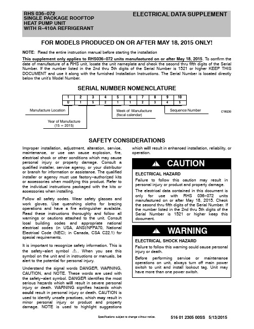
Specifications subject to change without notice.516 01 2305 00SS 5/13/2015RHS 036−072SINGLE PACKAGE ROOFTOP HEAT PUMP UNITWITH R −410A REFRIGERANTELECTRICAL DATA SUPPLEMENTFOR MODELS PRODUCED ON OR AFTER MAY 18, 2015 ONLY!NOTE : Read the entire instruction manual before starting the installationThis supplement only applies to RHS036−072 units manufactured on or after May 18, 2015. To confirm the date of manufacture of a RHS unit, locate the unit nameplate and check the second thru fifth digits of the Serial Number. If the number listed in the 2nd thru 5th digits of the Serial Number is 1521 or higher KEEP THIS DOCUMENT and use it along with the furnished Installation Instructions. The Serial Number is located directly below the unit’s Model Number.SERIAL NUMBER NOMENCLATUREC150230SAFETY CONSIDERATIONSImproper installation, adjustment, alteration, service,maintenance, or use can cause explosion, fire,electrical shock or other conditions which may cause personal injury or property damage. Consult a qualified installer, service agency, or your distributor or branch for information or assistance. The qualified installer or agency must use factory −authorized kits or accessories when modifying this product. Refer to the individual instructions packaged with the kits or accessories when installing.Follow all safety codes. Wear safety glasses and work gloves. Use quenching cloths for brazing operations and have a fire extinguisher available.Read these instructions thoroughly and follow all warnings or cautions attached to the unit. Consult local building codes and appropriate national electrical codes (in USA, ANSI/NFPA70, National Electrical Code (NEC); in Canada, CSA C22.1) for special requirements.It is important to recognize safety information. This is the safety −alert symbol . When you see this symbol on the unit and in instructions or manuals, be alert to the potential for personal injury.Understand the signal words DANGER, WARNING,CAUTION, and NOTE. These words are used with the safety −alert symbol. DANGER identifies the most serious hazards which will result in severe personal injury or death. WARNING signifies hazards which could result in personal injury or death. CAUTION is used to identify unsafe practices, which may result in minor personal injury or product and property damage. NOTE is used to highlight suggestionswhich will result in enhanced installation, reliability, or operation.2516 01 2305 00SSSpecifications subject to change without notice.Table 1 – RHS036−072 Unit Wire/Fuse or HACR Breaker Sizing DataU N I TN O M . V -P h -H ZIFM-TYPEELEC. HTRNO C.O. or UNPWR C.O.CRHEATER***A00Nom (kW)FLANO P .E.w/ P .E. (pwrd fr/unit)MCAMAX FUSE or HACR BRKR DISC. SIZEMCAMAX FUSE or HACR BRKR DISC. SIZE FLA LRA FLA LRA R H S 036208/230-3-60DD −STDNONE −−2530259727302799101A 3.3/4.49.2/10.637/3945/4535/37106/10839/4045/5037/39108/110102A 4.9/6.513.6/15.642/4550/5040/43111/11344/4750/5043/45113/115103B 6.5/8.718.1/20.948/5150/6046/49115/11850/5350/6048/51117/120104B 7.9/10.521.9/25.353/5760/6050/54119/12255/5960/6052/56121/124105A 12.0/16.033.4/38.567/7370/8063/69130/13669/7570/8065/71132/138MEDNONE −−23/2330/3022/2212625/2530/3024/24128101A 3.3/4.49.2/10.635/3645/4533/34135/13736/3845/4535/36137/139102A 4.9/6.513.6/15.640/4245/5038/40140/14242/4450/5040/42142/144103B 6.5/8.718.1/20.946/4950/5043/46144/14748/5150/6045/48146/149104B 7.9/10.521.9/25.350/5450/6047/51148/15152/5660/6050/53150/153105A 12.0/16.033.4/38.565/7170/8061/66159/16567/7370/8063/68161/167HIGHNONE −−26/2630/3026/2616228/2840/4028/28164101A 3.3/4.49.2/10.638/3945/4536/38171/17340/4150/5039/40173/175102A 4.9/6.513.6/15.643/4650/5042/44176/17845/4850/5044/46178/180103B 6.5/8.718.1/20.949/5250/6047/50180/18351/5460/6049/52182/185104B 7.9/10.521.9/25.354/5860/6051/55184/18756/6060/6053/57186/189105A 12.0/16.033.4/38.568/7470/8064/70195/20170/7670/8066/72197/203460-3-60DD −STDNONE −−1215124913151350106A 6.07.22125205622252257107A 8.810.62630246027302561108A 11.513.83030286331352964109A 14.016.83335316634353367MEDNONE −−1115106312151264106A 6.07.22020197021252071107A 8.810.62425237425252475108A 11.513.82830267729302778109A 14.016.83235308033353181HIGHNONE −−1315128114151382106A 6.07.22225218823252289107A 8.810.62630249227302693108A 11.513.83030289531352996109A 14.016.83435329835353399575-3-60DD −STD NONE −−1015103512151237MED NONE −−8157381015940HIGHNONE−−81584210151044See: Legend and Notes for Table 1 on page 6.Specifications subject to change without notice.516 01 2305 00SS3U N N O M . V TYPECRHEATER***A00Nom (kW)FLAMCAFUSE or HACR BRKR DISC. SIZEMCAFUSE or HACR BRKR DISC. SIZE FLA LRA FLA LRA R H S 048208/230-3-60DD −STDNONE −−2630269428402896102A 4.9/6.513.6/15.643/4650/5042/44108/11045/4850/5044/46110/112103B 6.5/8.718.1/20.949/5350/6047/50112/11551/5560/6049/52114/117105A 12.0/16.033.4/38.568/7570/8064/70127/13370/7770/8067/72129/135104B+104B 15.8/21.043.8/50.581/9090/9076/84182/19583/9290/10079/86184/197MEDNONE −−24/2430/3023/2312326/2630/3026/25125102A 4.9/6.513.6/15.641/4350/5039/41137/13943/4550/5041/43139/141103B 6.5/8.718.1/20.947/5050/5044/47141/14449/5250/6046/49143/146105A 12.0/16.033.4/38.566/7270/8062/67156/16268/7470/8064/70158/164104B+104B 15.8/21.043.8/50.579/8780/9074/81211/22481/8990/9076/83213/226HIGHNONE −−27/2740/4027/2715929/2940/4029/29161102A 4.9/6.513.6/15.644/4750/5043/45173/17546/4950/5045/47175/177103B 6.5/8.718.1/20.950/5450/6048/51177/18052/5560/6050/53179/182105A 12.0/16.033.4/38.569/7670/8066/71192/19871/7780/8068/73194/200104B+104B 15.8/21.043.8/50.582/9190/10078/85247/26084/9290/10080/87249/262460-3-60DD −STDNONE −−1315134714201448106A 6.07.22225215423252255108A 11.513.83030296131353062109A 14.016.83435326435353365108A+108A 23.027.7485045102495046103MEDNONE −−1215116113151262106A 6.07.22125196822252069108A 11.513.82930277530302876109A 14.016.83335307834353179108A+108A 23.027.7465043116475044117HIGHNONE −−1315137914201480106A 6.07.22225218623252287108A 11.513.83030299331353094109A 14.016.83435329635353397108A+108A 23.027.7485045134495046135575-3-60DD −STD NONE −−1115113913151341MED NONE −−91584211151044HIGHNONE−−91594611151148See: Legend and Notes for Table 1 on page 6.4516 01 2305 00SSSpecifications subject to change without notice.U N N O M . V TYPECRHEATER***A00Nom (kW)FLAMCAFUSE or HACR BRKR DISC. SIZEMCAFUSE or HACR BRKRDISC. SIZE FLA LRAFLA LRA R H S 060208/230-3-60DD −STDNONE −−294028121314530123102A 4.9/6.513.6/15.646/4850/5044/46135/13748/5050/6046/48137/139104B 7.9/10.521.9/25.356/6060/7053/57143/14658/6260/7056/59145/148105A 12.0/16.033.4/38.571/7780/8067/72154/16073/7980/8069/75156/162104B+104B 15.8/21.043.8/50.584/9290/10079/86209/22286/9490/10081/88211/224104B+105A 19.9/26.555.2/63.898/109100/11092/102231/249100/111100/12594/104233/251MEDNONE −−30/3045/4029/2918632/3245/4532/31188102A 4.9/6.513.6/15.647/4950/6045/47200/20249/5160/6047/49202/204104B 7.9/10.521.9/25.357/6160/7055/58208/21159/6360/7057/60210/213105A 12.0/16.033.4/38.572/7880/8068/73219/22574/8080/8070/76221/227104B+104B 15.8/21.043.8/50.585/9390/10080/87274/28787/9590/10082/89276/289104B+105A 19.9/26.555.2/63.899/110100/11093/103296/314101/111110/12595/105298/316HIGHNONE −−30/3045/4029/2918632/3245/4532/31188102A 4.9/6.513.6/15.647/4950/6045/47200/20249/5160/6047/49202/204104B 7.9/10.521.9/25.357/6160/7055/58208/21159/6360/7057/60210/213105A 12.0/16.033.4/38.572/7880/8068/73219/22574/8080/8070/76221/227104B+104B 15.8/21.043.8/50.585/9390/10080/87274/28787/9590/10082/89276/289104B+105A 19.9/26.555.2/63.899/110100/11093/103296/314101/111110/12595/105298/316460-3-60DD −STDNONE −−1520145816201659106A 6.07.22425236525302466108A 11.513.83235307233353173109A 14.016.83640347537403576108A+108A 23.027.7505046113516047114108A+109A 25.530.7536050119546051120MEDNONE −−1520159016201691106A 6.07.22425239725302498108A 11.513.8323530104333532105109A 14.016.8364034107374035108108A+108A 23.027.7505046145516048146108A+109A 25.530.7536050151546051152HIGHNONE −−1520159016201691106A 6.07.22425239725302498108A 11.513.8323530104333532105109A 14.016.8364034107374035108108A+108A 23.027.7505046145516048146108A+109A 25.530.7536050151546051152575-3-60DD −STD NONE −−1215124514201447MED NONE −−1015105212151254HIGHNONE−−1115116313151365See: Legend and Notes for Table 1 on page 6.Specifications subject to change without notice.516 01 2305 00SS5U N N O M . V TYPECRHEATER***A00Nom (kW)FLAMCAFUSE or HACR BRKRDISC. SIZEMCAFUSE or HACR BRKRDISC. SIZE FLA LRAFLALRAR H S 072208/230-3-60STDNONE −−325030159345032161102A 4.9/6.513.6/15.649/5160/6046/48173/17551/5360/6048/50175/177104B 7.9/10.521.9/25.359/6360/7055/59181/18461/6570/7058/62183/186105A 12.0/16.033.4/38.573/8080/8069/75192/19875/8280/9071/77194/200104B+104B 15.8/21.043.8/50.586/9590/10081/88247/26088/9790/10083/91249/262104B+105A 19.9/26.555.2/63.8101/111110/12594/104269/287103/113110/12596/106271/289MEDNONE −−35/3550/5034/3421237/3750/5036/36214102A 4.9/6.513.6/15.652/5460/6050/52226/22854/5660/6052/54228/230104B 7.9/10.521.9/25.362/6670/7059/63234/23764/6870/8061/65236/239105A 12.0/16.033.4/38.577/8380/9072/78245/25179/8580/9075/80247/253104B+104B 15.8/21.043.8/50.590/9890/10084/92300/31392/100100/10086/94302/315104B+105A 19.9/26.555.2/63.8104/115110/12597/107322/340106/116110/125100/109324/342HIGHNONE −−35/3550/5034/3421237/3750/5036/36214102A 4.9/6.513.6/15.652/5460/6050/52226/22854/5660/6052/54228/230104B 7.9/10.521.9/25.362/6670/7059/63234/23764/6870/8061/65236/239105A 12.0/16.033.4/38.577/8380/9072/78245/25179/8580/9075/80247/253104B+104B 15.8/21.043.8/50.590/9890/10084/92300/31392/100100/10086/94302/315104B+105A 19.9/26.555.2/63.8104/115110/12597/107322/340106/116110/125100/109324/342460-3-60STDNONE −−1420137715201478106A 6.07.22325228424302385108A 11.513.83135299132353092109A 14.016.83535339436403495108A+108A 23.027.7495045132505046133108A+109A 25.530.7526049138536050139MEDNONE −−162015104172016105106A 6.07.2253023111263025112108A 11.513.8333531118343532119109A 14.016.8374035121384036122108A+108A 23.027.7505047159516048160108A+109A 25.530.7546050165556052166HIGHNONE −−162015104172016105106A 6.07.2253023111263025112108A 11.513.8333531118343532119109A 14.016.8374035121384036122108A+108A 23.027.7505047159516048160108A+109A 25.530.7546050165556052166575-3-60STD NONE −−1115106413151266MED NONE −−1215127914201481HIGHNONE−−1215127914201481See: Legend and Notes for Table 1 on page 6.Legend and Notes for Table 1LEGEND:BRKR−Circuit breakerCO−Convenience outletDD−Direct drive (indoor fan motor)DISC−DisconnectFLA−Full load ampsIFM−Indoor fan motorLRA−Locked rotor ampsMCA−Minimum circuit ampsMOCP−MAX FUSE or HACR BreakerPE−Power exhaustUNPWR CO−Unpowered convenient outlet NOTES:1.In compliance with NEC requirements for multimotorand combination load equipment (refer to NEC Ar-ticles 430 and 440), the overcurrent protective device for the unit shall be fuse or HACR breaker. Canadian units may be fuse or circuit breaker.2.Unbalanced 3-Phase Supply VoltageNever operate a motor where a phase imbalance in supply voltage is greater than 2%. Use the following formula to determine the percentage of voltage imbal-ance.% Voltage Imbalance= 100 x max voltage deviation from average voltageaverage voltageExample: Supply voltage is 230-3-60AB = 224 vBC = 231 vAC = 226 vAverage Voltage =(224 + 231 + 226)=68133=227Determine maximum deviation from average voltage.(AB) 227 – 224 = 3 v(BC) 231 – 227 = 4 v(AC) 227 – 226 = 1 vMaximum deviation is 4 v.Determine percent of voltage imbalance.% Voltage Imbalance= 100 x4227= 1.76%This amount of phase imbalance is satisfactory as it is below themaximum allowable 2%.IMPORTANT: If the supply voltage phase imbalance is more than2%, contact your local electric utility company immediately.Copyright 2015 International Comfort ProductsLewisburg, Tennessee 37091 USA6516 01 2305 00SSSpecifications subject to change without notice.。
BR盐雾试验机英文版说明书
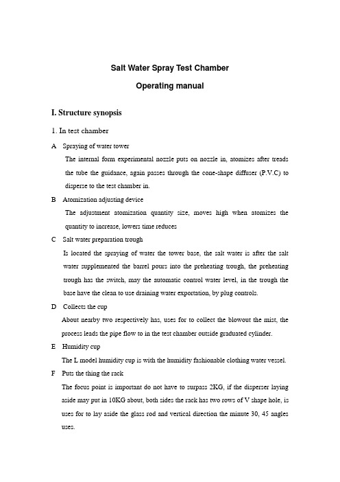
Salt Water Spray Test ChamberOperating manualI. Structure synopsis1. In test chamberA Spraying of water towerThe internal form experimental nozzle puts on nozzle in, atomizes after treads the tube the guidance, again passes through the cone-shape diffuser (P.V.C) to disperse to the test chamber in.B Atomization adjusting deviceThe adjustment atomization quantity size, moves high when atomizes the quantity to increase, lowers time reducesC Salt water preparation troughIs located the spraying of water the tower base, the salt water is after the salt water supplemented the barrel pours into the preheating trough, the preheating trough has the switch, may the automatic control water level, in the trough the base have the clean to use draining water exportation, by plug controls.D Collects the cupAbout nearby two respectively has, uses for to collect the blowout the mist, the process leads the pipe flow to in the test chamber outside graduated cylinder.E Humidity cupThe L model humidity cup is with the humidity fashionable clothing water vessel.F Puts the thing the rackThe focus point is important do not have to surpass 2KG, if the disperser laying aside may put in 10KG about, both sides the rack has two rows of V shape hole, is uses for to lay aside the glass rod and vertical direction the minute 30, 45 angles uses.Test chamber control temperature installment.H Filtrating equipmentUses for to filter in the salt water the impurity.I Isolates the water troughThe isolation temperature prevented the smog divulgesJ Heats up the water troughIn the test chamber base, installs the water to heat up causes the test chamber temperature balance, the function is heats up with the heat preservation.2 Test chamber exteriorK Dry bulb temperature ideaTests in the laboratory the temperatureL Wet-bulb thermometerTests in the laboratory the humidityM Counts graduated cylinderThe collection each time experiments atomization quantity.N Saturated spatial air drumLays aside in the control box the base, the function lies in to the air adds the temperature and the humidity, then delivers in the test chamber the nozzle.O Salt water supplement barrelIn automatic supplement salt water preheating trough salt waterP Experimental coverThe drift angle 100 angles, use in to cover in the test chamber place above.Q Air ventOutside the caliber pipeline by 11/2’’, discharges the mist the pipe to receive,causes the mist to discharge.R Draining water exportationOutside the caliber pipeline by 1/2’’, discharges the water receives the drain,causes the waste water to discharge from here.The caliber pipeline by 1/2’’, the connection adds the water pipe to the preheating water trough and the saturated spatial air drumT Supplements the salt water the barrel water level measuring applianceU The air reduced pressure filter, the machine works above for 24 hours, underneath the filter has draining water the exportation, gently upwardly presses the draining water exportation, or always barometric pressure closure.3. Control system(1) test chamber temperature controller pneumatic control test chamber temperature,according to standard temperature hypothesis, salt water testing method 35 ℃, anti-corrosive testing method 50 ℃.(2) test chamber water level insufficient - like test chamber water level insufficient,the indicating lamp is bright, also the electromagnetism valve circuit,automatically enters the water until the full water level namely to extinguish. (3) normal like test chamber and saturation tank water level insufficient, theindicating lamp is bright, expression normal state.(4) saturation tank water level insufficient like saturated spatial air drum water levelinsufficient, the indicating lamp is bright, also the electromagnetism valve circuit, automatically enters the water until the full water level namely to extinguish. (5) saturated spatial air drum temperature controller control saturated spatial airdrum temperature general temperature hypothesis, salt water testing method47 ℃, anti-corrosive testing method 63 ℃.(6) pressure gauge this table demonstrated the pressure which the pressure is the airheats up after the saturated spatial air drum, transmits when spray nozzleachieved.(7) the timer may wilfully establish the laboratory to need the time, after hadfinished auto-stop.(8) pressure-regulating valve this valve is the air pressure when outdoes lowly,borrows presses the table to demonstrate adjusts. (Test condition 1kg)(9) accumulates when straight reads type 0~9999.9hr to be possible to instructaccumulation the experimental time.(10) the power switch controls the entire machine total power source.(11) the console switch controls the test chamber to heat up the trough and thesaturation tank spatial air drum electricity heat pipe power source.(12) atomizes the switch control compressed air to enter the test chamber to causethe spray nozzle atomization.(13) timer switch control timer power source.(14) the defogging switch uses to control the test chamber to remove the mist. II.Installs the notice and the matters needing attention:1. The power source is: AC 1ф 220V 20A 50Hz2. The machine lays aside in behind to wall approximately 40cm, about two sides must reserve the service space.3. Outside the machine pessimistic electric wire is the total power line, the power line please again installs a non- melt silk switch or the knife switch. 6 meter fast air compression pipe joint to is spatial (U).4. The water entrance may use PVC 1/2 "hard tube or the soft pipe joint running water source.Draining water place may use PVC 1/2 "hard tube or the hose discharges, must pay attention to the water pipe to be supposed downward, also cannot be higher than the exhaust pipe.The air vent must with PVC 11/2 "hose, extend to outside discharges, must pay attention to the exhaust pipe the installment, may parallel be upward by the machine or be parallel to under. (Upward when must not affect (when transparent experimental cover opens) above installs the PVC hard tube, margin place does not have residual to model Rubber dust, otherwise electromagnetism valve is easy to block, creates not good phenomenon).5. The machine installment position, please avoid the sunlight direct radiation, in order to avoid condition of the influence test.6. The machine installment position, should not approach other electric appliance equipment as far as possible or be flammable, in order to avoid danger.7. This machine is the PVC revertex makes, please do not make an effort to collide, in order to avoid cracks. The application temperature please do not surpass the experimental standard scope, in order to avoid because of hot has distorted or the breakdown.8. Hypothesis experiment time 0~999.9HR.9. Presses down the atomization to press a keyA. the valve which lets in air the air compressor front to openB. to transfer to the air compressor pressure relief valve pressure of the 2~3kg/cm2(clockwise increase, anti-clockwise reduction).C. transfers to the pressure-regulating valve pressure of the 1kg/ cm2, its pressuremay know by the pressure gauge. (Clockwise increase, anti-clockwisereduction).10. Presses down the time pressed key, then may depend on the hypothesis time, thetime finished the automatic power failure.11. The experiment finished, according to order each switch closure.12. In the experiment like has exceptionally, please refers to the functionexceptionally to judge table processing.III. The operation explained1. Mixes the experimental solutionTo mix the method: The 9.5L pure distilled water, joins 500gNaCl, performs to stir, causes its full dissolution. (this time salt water density is 5%)2. Pours into the salt water fluid note entrance the liquid medicines, causes the medicine current of water to the salt water preheating trough.3. The cup watering, the wet-bulb thermometer will cover the gauze, the gauze terminal is setting in the cup.4. The laying aside previews or the test specimen in sets at the thing on * ornaments angle to depend on needs the standing operating procedure to decorate5. The hypothesis experiment temperature* depends on must experiment the standing operating procedure to decorateA The salt water testing method: Test chamber temperature 35℃saturated spatial air drums temperatures 47 ℃B Corrosion testing method: The test chamber temperature 50 ℃saturated spatial air drums temperatures 63 ℃6. Press down the power source, operates the pressed key, first pre- warm, uses for to arrive the hypothesis temperature.* The attention will have to experiment the lid to cover. (For example water level is insufficient indicating lamp is bright, then will be able automatic controlsupplement water level, will shine until normal indicating lamp, will be allowed to operate).7. The hypothesis experiment time8. Presses down the time, the air compressor two pressed keys carries on the experiment.* Presses down the atomization pressed key if does not have the gas to leave, looks up behind the air compressor the switch admission valve and the adjusting valve whether do open.* In the test chamber like must regarding as, press down removes the mist switch outside, causes the mist rapidly to discharge.9. The experiment finished, according to order each switch closure.* Like will experiment the time-gap to the next time long, will ask Yu Cici to experiment finished, cleans the test chamber interior to maintain the machine to be cleanVI. Judgment and address when function out of function:V. Maintenance item1. The experimental time like will for surpass a month,please to heat up in thewater trough the water replacement.2.The experiment uses the salt water fluid like to surpass a week of use ,please notagain not to use .in order to avoid affects the test quality.3.The experimental time surpasses for 120 hours,Whenever this time,The pondingdischarges the air compressor in.Underneath the knob relaxes the air compressor4. The experimental time surpasses for 2000 hours,Please replace in the aircompressor the machine oil.When replacement air compressor machine oil do not start the air compressor5.When will experiment the time to the next time longer, to invite this experimentfinished to clean the test chamber interior and to heat up in the trough the water to discharge.。
LAQUAtwin-Na-11盐氮檢測仪操作手冊说明书

CODE: GZ0000460286Instruction Manual (Operation)COMPACT WATER QUALITY METER LAQUAtwin-Na-11SpecificationsItems in packageConsumable parts sold separately Part NamesNotePress the switches 0.5 seconds or more unless otherwise specified.Initial SetupAttaching/detaching the sensorNoteBe careful not to twist the waterproof gasket.Inserting/removing batteriesElectrode conditioningNote●Before using the sensor for the first time or after several days of disuse, perform electrode conditioning.●Perform calibration after electrode condition-ing.1.Place some drops of 2000 ppm standard solution to the flat sensor.2.Wait a few hours before use.There is no need to switch the meter ON.3.Clean the flat sensor with running water.ModelLAQUAtwin-Na-11Target Sodium ion (Na +)Measurement principle ISE method Minimum sample volume More than 0.3 mL *1Measure-ment range2 to 9900 [unit: ppm or mg/L]Resolution (default)Display range:Resolution 2 to 99:1100 to 990:101000 to 9900:100[unit: ppm or mg/L]Calibration Up to 2 pointsDefault: 150 ppm and 2000 ppm Accuracy *2±10% of reading valueWaterproofIP67 (no failure when immersed in water at a depth of 1 m for 30 min) *3Display Custom (monochrome) digital LCDwith backlightOperating environment Temperature: 5︒C to 40︒CHumidity: 85% relative humidity orless (no condensation)Power CR2032 batteries (⨯2)Battery life Approx. 400 h continuous operation(backlight off mode)*4Material ABS epoxy (main material)Dimensions 164 ⨯ 29 ⨯ 20 mm (excluding projec-tions)Mass Approx. 50 g (excluding batteries)*10.05 mL or more if sampling sheet B (sold sepa-rately) is used.*2The closeness of agreement between a mea-sured value and an actual value of standard solu-tion after two-point calibration using 150 ppm and 2000 ppm standard solutions.●The standard solution used for the later cali-bration was measured after two-point calibra-tion at 150 ppm and 2000 ppm.●The calibration and measurement are per-formed at the same temperature.●The error of standard solutions and rounding error (±1 digit) are not included.*3The meter cannot be used underwater.*4When the backlight is used, battery life willshorten.ItemsQuantitySensor S0221Meter1Storage case 1BatteriesCR20322Standard solution150 ppm 12000 ppm1Pipette1Sampling sheet B (5 sheet-pack)1Instruction manual (Operation)1Instruction manual (Before use)1Items Specifications Part No.SensorS022, Na +3200459867Standard solution Y022L, Na + 150 ppm3200457724Y022H, Na + 2000 ppm 3200457723Sampling sheet BY046, 100 sheet-pack 32000538581Flat sensor2Light shield cover 3Liquid junction 4Response mem-brane 5Lithium batteries 6MEAS switch 7ON/OFF switch 8CAL switch9Waterproof gasket 10Strap eyeletAttaching the sensor 1.Power OFF the meter.2.Confirm that the waterproofing gasket is clean and undamaged.3.shown.Detaching the sensor 1.Power OFF the meter.2.Lift the sensor tongue tip and slide the sensor a little away from the meter.3.Pull out the sensor all the way from the meter. Inserting the batteries 1.Power OFF the meter.2.Slide both batteries into the battery case as shown.Be sure to use two CR2032 batteries, and put them with the plus sides(+) upwards.Removing the batteries 1.Power OFF the meter.e a ball-point pen or other tool to pry the batter-ies out from the clips as shown.Basic OperationCalibrationCalibration is required before measurement.Use standard solution within the measurement range in the specifications. See also the tip of “How to select standard solution” below.Tip●Calibration values are saved even if the meteris switched OFF.●Calibration value is rewritten if calibration isrepeated using the same standard solution.TipHow to select standard solution:The following table show an example of the rela-tionship between the concentrations of targeted samples and standard solution used for calibra-tion.For accurate measurement, calibrate using 2points of standard solution with a tenfold or moreconcentration difference encompassing the tar-get concentration.When the concentration to be measured is veryhigh or very low, accuracy may be poorer.MeasurementPower ON1.Press and hold the ON/OFF switch.The power is switched ON,and the meter modelnumber is displayed on theLCD.Power OFF1.Press and hold the ON/OFF switch.The power is switched OFF.Calibration pointsThe number of calibration points is up to 2.Multi-point calibration1.Set the concentrations of standard solutionfor calibration referring to " 1st calibra-tion point setting" (page 5) and " 2nd cal-ibration point setting" (page 5).The 1st point is set to 150 ppm and the 2ndpoint is set to 2000 ppm by the default.2.Open the light shield cover and place somedrops of the standard solution on the flatsensor taking care to cover the entire flatsensor.Rinsing the sensor with the standard solutionbeforehand will provide a more accuratecalibration as it will reduce sample crossovercontamination.3.Close the light shield cover and press theCAL switch.The meter enters the CAL mode and blinks thedisplay of the set 1st-point concentration.Pressing the MEAS switch switches thedisplayed value between the setconcentrations.4.With the set concentration of the 1st pointdisplayed.After the calibration is complete,stop blinking and the measured value isdisplayed.The calibration value at 25 C is displayed for 1s and the display returns to the measurementmode automatically.5.Open the light shield cover and remove thestandard solution. Then remove moistureon the sensor by gently dabbing with a softtissue.This completes the 1st point calibration.6.To perform 2nd point calibration, repeatsteps 2. to 5.Calibration errorIf blinks and Er4 (error dis-play) appears, the calibrationhas failed.Perform electrode conditioning.Check that the correct standard solution is used,and repeat calibration after cleaning the sensor.If the calibration repeatedly fails when using thecorrect standard solution(s), the sensor mayhave deteriorated. Replace the sensor with newone.[unit: ppm]Targeted sampleconcentrationStandard solutionLow High200020009000150150200015 15*150*How to prepare 15 ppm standard solution:Mix one part 150 ppm standard solution to 9 partspurified water (1:9 volume ratio).Sample setting1.Open the light shield cover and put somedrops of sample on the flat sensor to coverthe entire flat sensor.2.Close the light shield cover.Measurement modeThe auto stable (AS) mode and the auto hold(AH) mode can be selected. Refer to " Mea-surement mode change" (page 5) for the opera-tion to set the measurement mode.Auto stable (AS) mode1.Confirm that the meter is in the measure-ment mode, and place a sample on the sen-sor.locked.2.appears.Auto hold (AH) modeand will not change until the MEAS switch ispressed for the next measurement.1.Confirm that the meter is in the measure-ment mode, and place a sample on the sen-sor.2.Press the MEAS switch.The auto hold function isactivated.blinks until themeasured value hasstabilized.When the measured value is stable, stopsblinking and the displayed value is locked with3.Document the displayed value.4.Press the MEAS switch.disappears.Be sure to perform this step before starting thenext measurement. Or, you may mistake thedisplayed hold value for the next measuredvalue.●If a measured value is out of the specifiedmeasurement range, "Or" is displayed for upper range and "Ur" is displayed for under range.●When you have a problem with the calibrationor measurement, refer to frequently asked questions.Sampling sheetFor a minute sample●Note that reaction between sample and sam-pling sheet B may affect the measured value.●Handle sampling sheet B with tweezers tominimize possible contamination.●Be sure to close the light shield cover duringmeasurement to minimize possible sample evaporation.For a sample containing tiny particles If tiny particles are contained in a sample, such as an extract from soil, the particles influence measurement results. Use the sampling sheet holder cover and sampling sheet B sold sepa-rately to counteract the influence.The sampling sheet holder cover does not shield the sensor from light, which affects the sensor. When using the sampling sheet holder cover, shield the flat sensor from light with an alterna-tive.1.Replace the light shield cover with the sam-pling sheet holder cover.2.Put a piece of sampling sheet B on the flatsensor and close the sampling sheet holder cover.3.Put 4 or 5 drops of sample on the samplingsheet B.The display mode switches among concentration(the unit depends the setting), temperature, andvoltage by pressing the MEAS switch in the ASmode.MaintenanceAppendixInterfering ionsSelectivity coefficient is a concentration ratio ofthe interfering ion against the target ion, whichaffects the target ion measurement value. Forexample, selectivity coefficient of interfering ionagainst target ion is 1 ⨯ 10-2, which means for thesame concentration of interfering ion and targetion coexisting in a sample, the target measure-ment shows approximately 1 ⨯ 10-2 (1%) higherresult.minute sample.covered with only 50to 100 μL sample.Storage1.Clean the sensor with tap water.2.Dab gently with soft tissue or cloth toremove moisture on the sensor and meter.NoteEspecially be sure to treat the flat sensor gentlyto prevent damaging it.3.Close the light shield cover and the slidecap before storing the meter.Temperature sensor adjustmentTo perform accurate measurement with correc-tion for temperature effects, follow the stepsbelow. Normally this is not necessary.1.Ready a reference thermometer, and allowthe meter and reference thermometer toreach to room temperature.2.Set the display mode to temperature refer-ring to " Measurement display change"(page 3).3.Press the CAL switch.The meter displays the setting screen fortarget temperature.4.Press the MEAS switch to adjust the dis-played temperature on the meter to matchthe temperature indicated by the referencethermometer.Pressing the MEAS switch increases thedisplayed temperature. After the displayedtemperature reaches 40°C, it returns to 5°C.5.Press the CAL switch again to apply thedisplayed value to the adjustment.The adjustment starts. The adjusted valueblinks with and displayed.After the adjustment is complete, the adjustedvalue stops blinking with MEAS anddisplayed.If Er4 (error display) appears, the adjustmenthas failed. Retry the above steps increasingthe time spent on the step 1.If the adjustment repeatedly fails, the sensormay have deteriorated. Replace the sensorwith new one.Initializing calibration dataInitialize calibration in the following cases.●To delete the calibration data●If the number of points for the last calibration isuncertain.●After the sensor is replaced.1.Press and hold the CAL and ON/OFFswitches for over 3 seconds when themeter is switched OFF to Initialize calibra-tion.After a moment of all segment indication, thesoftware version is displayed.And then, the displaychanges as shown right.2.Press the CAL switch.All calibration data is reset.When the initialization ofcalibration data is complete,End appears.The meter automatically switches OFF.Initializing the settingsAll setup choices are erased. The meter is resetto the factory default values.1.Press and hold the MEAS, CAL and ON/OFFswitches for over 3 seconds when themeter is switched OFF to enter the initial-ization.After a moment of all segment indication, thesoftware version is displayed.And then, the displaychanges as shown right.2.Press the CAL switch.All calibration data is reset.When the initialization ofsettings is complete, Endappears.The meter automatically switches OFF.Target Sodium ion (Na+)Interfering ions andselectivity coefficientsK+, Rb+: 1 ⨯ 10-2(at 10-3 mol/L Na+)pH range 3 pH to 9 pH(at 10-3 mol/L Na+)Frequently asked questionsEr4 is dis-played during the calibra-tion Please note that if you press the CAL switch in mV or temperature display mode, Er4 is displayed. This is because there is no calibration facility available for these modes.Er1 is dis-played soon power ON.The internal IC in the meter may be defective. Perform meter initializa-tion.If Er1 is still displayed after the initial-ization, the internal IC in the meter is defective. Replace the meter with a new one (the meter cannot be repaired).Er2 is dis-played right after power ON.The internal IC in the meter is defec-tive. Replace the meter with a new one (the meter cannot be repaired).Er3 is dis-played right after power ON.The internal IC in the meter is defec-tive. Replace the meter with a new one (the meter cannot be repaired).What factors interfere measure-ment?Acids influence measurement results. Measure within the range from 3 pH to 9 pH. Also, high-level monovalent cations, such as K+, may cause measurement errors. Refer to " Interfering ions" (page 3) for details.Are there any helpful tips or precautions to be aware for measure-ment?When the sample amount is enough, washing the sensor twice or so with the sample allows more accurate measurement.Residue between the light shield cover and flat sensor prevents accu-rate measurement. Before measure-ment of the next sample, wash the sensor with tap water and remove moisture.Question AnswerCan I pre-pare stan-dard solutions myself?You can prepare standard solutions by dissolving sodium chloride in ion-exchanged water to the specified concentration.Question AnswerSetup ModeThe setup mode allows the user to customize the meter to his specific needs.To enter the setup mode, press and hold the MEAS and ON/OFF switches for over 3 seconds when the meter is switched OFF. All the LCD segments appear and then the meter enters the setup mode.Tip●To have the changes apply, you need to go through the entire steps from “Setup mode entry” to “Setup completion” shown below. To leave a setting as it is, just press CAL switch in the setting.●To exit the setup mode with no change of settings, press the ON/OFF switch earlier than pressing CAL switch in the last step but one, or the “Backlight setting” step.Setup mode entryUnit settingThe display units can be changed.1st calibration point settingThe concentration of the 1st calibration point can be set.NoteIf you changed either of the calibration concentration settings, calibrate again at the both set concentrations before mea-surement. When either calibration concen-tration is changed, the calibration data are initialized.2nd calibration point settingThe concentration of the 2nd calibration point can be set.*In calibration point setting, pressing the MEAS switch increases the displayed value. After the displayed value reaches 9800, it returns to 3.Measurement mode changeThe measurement mode can be switched.* Measurement display change is available in the AS mode. Refer to " Measurement display change" (page 3).Multiplying compensation settingThe coefficient (0.01 to 9.90) to be applied to the measured value can be set. The compensated result is displayed as the measured value. The default setting is 1.00.Backlight settingThe backlight can be switched to ON or OFF.Setup completion31, Miyanonishi-cho, Kisshoin Minami-ku, Kyoto,。
盐份计说明书
盐分计使用说明日常生活中食入太多盐会导致高血压。
研究表明日常生活中每天食用10克盐的人群造成高血压的几率大大提高。
我们应该每天摄入盐的量应小于10克。
盐分计使用导电性测试来衡量液体食物的盐浓度。
可以有效控制每日盐的摄入量,更好的维护健康。
盐分计含一个轻触按扭,七个红色指示灯来指示盐的浓度,绿色电源指示灯,操作方便,使用简单。
它将成为您理想的健康伴侣。
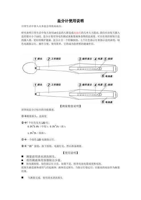
【测量数值说明】请参阅盐分计标出的功能描述。
①→测量探头:盐浓度③→7个红色发光LED灯;0.3%~0.6%(中度);0.8%~1%(浓);1.3%~2%(很浓)。
④→一个绿色LED电源指示灯。
⑤→“ON”按钮:按下按钮,电源灯亮,然后准备测量。
【使用说明】⏹测量前用清水清洗探头。
⏹将待测液体用容器取出少量。
⏹按电源按钮。
绿色指示灯点亮。
如果不是,检查电池电量或更换电池。
把探头插进液体或用勺舀起液体,液体没过探头。
当指示灯稳定后,以最高的阅读作为衡量结果。
⏹当测量完成,使用清水清洗探头【规格】电池要求:4*1.5=6V AG13*4负载电流:最大20mA(所有LED全亮)产品尺寸:252*26*15.5(mm)产品重量:约36 克测量范围:0.3%~2.0%使用温度范围:60℃~80℃公式:盐含量=总量×浓度例如:总质量的玻璃溶液150克,其浓度为0.5%150克×0.5% =0.75g【电池更换】电压较低时,绿色电源灯将不亮。
这表明,电池电量低,电池需要更换。
拆下电池盖并取出四废旧电池处理妥当,避免儿童接触。
把4只新电池装进电池盒(请注意正负方向)。
清洗:用干净的水冲洗或用中性洗涤剂清洗探头。
不要使用水或穿中性洗涤剂清洗的机体。
不要使用酒精,稀释剂、汽油清洗探头和机体。
保管避免强烈振动,否则容易出现故障。
不要长时间阳光照色或放于潮湿处。
长时间不用,请拆下电池。
温州康之健电子科技有限公司。
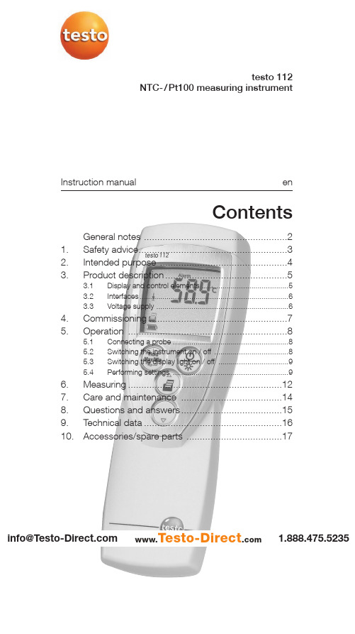
Testo 112 NTC- Pt100 测量仪使用说明书
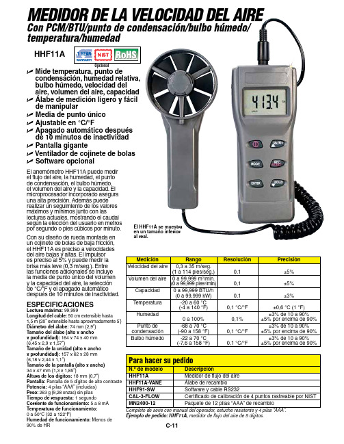
Instruction manual entesto 112NTC-/Pt100 measuring instrumentContentsGeneral notes ......................................................21.Safety advice........................................................32.Intended purpose ................................................43.Product description. (5)3.1Display and control elements ..........................................53.2Interfaces........................................................................63.3Voltage supply . (6)4.Commissioning ....................................................75.Operation (8)5.1Connecting a probe ........................................................85.2Switching the instrument on / off ....................................85.3Switching the display light on / off ..................................95.4Performing settings .. (9)6.Measuring..........................................................127.Care and maintenance ......................................148.Questions and answers......................................159.Technical data....................................................1610.Accessories/spare parts (17)1.888.475.5235*********************www.Testo-Direct .comGeneral notes2General notesThis chapter provides important advice on using this documentation.The documentation contains information that must beapplied if the product is to be used safely and efficiently.Please read this documentation through carefully andfamiliarise yourself with the operation of the product beforeputting it to use. Keep this document to hand so that youcan refer to it when necessary.Identificationachieved via the steps described.Where steps are numbered,you must always follow the order given!Condition A condition that must be met if an action is to be carried out as described.i ,1,2,...Step Carry out steps.Where steps are numbered,you must always follow the order given!TextDisplay text Text appears on the instrument display.Control buttonPress the button.-ResultDenotes the result of a previous step.ºCross-reference Refers to more extensive or detailedinformation.Button 1.888.475.5235*********************www.Testo-Direct .com1. Safety advice31.Safety adviceThis chapter gives general rules which must be followedand observed if the product is to be handled safely.Avoid personal injury/damage to equipmenti Do not use the measuring instrument and probes tomeasure on or near live parts.i Never store the measuring instrument/probes togetherwith solvents and do not use any desiccants.Product safety/preserving warranty claimsi Operate the measuring instrument only within theparameters specified in the Technical data.i Always use the measuring instrument properly and for itsintended purpose. Do not use force.i Do not expose handles and feed lines to temperatures inexcess of 70 °C unless they are expressly permitted forhigher temperatures.Temperatures given on probes/sensors relate only tothe measuring range of the sensors.i Open the instrument only when this is expresslydescribed in the documentation for maintenance andrepair purposes.Carry out only the maintenance and repair work that isdescribed in the documentation. Follow the prescribedsteps when doing so. For safety reasons, use onlyoriginal spare parts from Testo.Ensure correct disposali Take faulty rechargeable batteries/spent batteries to thecollection points provided for them.i Send the product back to Testo at the end of its usefullife. We will ensure that it is disposed of in an*********************environmentally friendly manner. 1.888.475.52352. Intended purpose42.Intended purposeThis chapter gives the areas of application for which theproduct is intended.Use the product only for those applications for which it wasdesigned. Ask Testo if you are in any doubt.testo 112 is a compact, accurate measuring instrument formeasuring temperatures by means of plug-in temperatureprobes. Thanks to the possibility of connecting not onlyNTC probes, but also Pt100 probes, the testo 112 coversa wide measurement range and at the same time providesa high level of measurement accuracy.The following components of the product are designed for continuouscontact with foodstuffs in accordance with the regulation(EC) 1935/2004:The measurement probe up to 1 cm before the probe handle or theplastic housing. If provided, the information about penetration depthsin the instruction manual or the mark(s) on the measurement probesshould be noted.The product was designed for the followingtasks/applications:·Food sector·Laboratories·Applications requiring official calibration (only relevant forGermany):The testo 112 is approved for official calibration by thePhysikalisch-Technisches Institut PTB (nationalmetrology institute in Germany).Approval mark:The product should not be used in the following areas:·Areas at risk of explosion·Diagnostic measurements for medical purposes*********************1.888.475.52353. Produktbeschreibung 53.Product descriptionThis chapter provides an overview of the components of the product and their functions.3.1Display and control elementsOverviewInfrared interface, probe socket Display Control buttons Battery compartment (rear)Button functionsButton Functions Switch instrument on; switch instrument off (press and hold)In configuration mode: 1.888.475.5235*********************www.Testo-Direct .com3. Production description6Important displayscharged3.2InterfacesInfrared interfaceMeasurement data can be sent to a Testo printer via theinfrared interface on the head of the instrument.Probe socketA plug-in measuring probe can be connected via the probesocket on the head of the instrument.3.3Voltage supplyVoltage is supplied by means of a 9V monobloc battery(included in delivery) or rechargeable battery. It is notpossible to run the instrument from the mains supply orcharge a rechargeable battery in the instrument.*********************1.888.475.52354. Commissioning7missioningThis chapter describes the steps required to commissionthe product.²Removing t t he p p rotective f f ilm o o n t t he d d isplay:i Pull the protective film off carefully.²Inserting a a b b attery/rechargeable b b attery:1To open the battery compartment on the rear of theinstrument, push the lid of the battery compartment inthe direction of the arrow and remove it.2Insert a battery/rechargeable battery (9V monobloc).Observe the polarity!3To close the battery compartment, replace the lid ofthe battery compartment in position and push itagainst the direction of the arrow.*********************1.888.475.52355. Operation85.OperationThis chapter describes the steps that have to be executed frequently when using the product.5.1Connecting a probePlug-in probesPlug-in probes must be connected before the measuringinstrument is switched on so that they are recognised bythe instrument.i Insert the connector of the probe into the probesocket.5.2Switching the instrument on /off²Switching tt he i i nstrument o o n: i Press .- A segment test is carried out: All LCD-segments inthe display briefly light up.- A function test of the instrument and the probe is carried out. The instrument tests the entire measurement channel regarding the adherence to allowed margins of error.The type of probe attached is displayed for approx.2s (NTC or Pt 100).An error is detected:-rEF Error is displayed for approx. 2s, then ----- is displayed. Please contact your dealer or Testo customer service.The function test was successful:-Measurement view is opened: The current reading is displayed.1.888.475.5235*********************www.Testo-Direct .com5. Operation9²Switching t t he i i nstrument o o ff:i Press and hold (for approx. 2s) until the displaygoes out.5.3Switching the displaylight on/off²Switching t t he d d isplay l l ight o o n/off:The instrument is switched on.i Press .5.4Performing settings1To o o pen c c onfiguration m m ode:The instrument is switched on and is in measurementview. Hold, Max or Min are not activated.i(for approx. 2s) until the displaychanges.-The instrument is now in configuration mode.(for approx. 2s) until thechanges that have already been made in configurationmode will be saved.2To s s et t t he a a larm f f unction:Configuration mode is opened, ALARM is lit.1/and confirm·oFF: Switches the alarm function off.·on: Switches the alarm function on.oFF was selected:ºContinue with objective T O SET THE MAX./MIN. PRINTFUNCTION.1.888.475.5235 *********************5. Operation10on was selected:2to set the value for the upper alarm3to set the value for the lower alarm3To s s et t t he m m ax./min. p p rint f f unction:MaxMin is flashing.i/and confirm·on: Maximum and minimum values are printed outas well when current or recorded readings areprinted.·oFF: Maximum and minimum values are not printedout as well when current or recorded readings areprinted.4To s s et A A uto O O ff:Configuration mode is opened, AutoOff is flashing.i/and confirm·on: The measuring instrument switches offautomatically if no button is pressed for 10min (Holdor Auto Hold is lit).·oFF: The measuring instrument does not switchitself off automatically.5To s s et t t he d d ate/time:Configuration mode is opened, YEAR is lit.1to set the current YEAR and confirm2to set the other values for the month() and time (TIME) and confirm each*********************1.888.475.52355. Operation116To s s et t t he u u nit o o f m m easurement:Configuration mode is opened, UNIT is lit.i/7To r r eset:Configuration mode is opened, RESET is lit.i and confirm·no: Instrument is not reset.·Yes: Instrument is reset. The instrument is reset tothe factory settings.The setting of date/time is not reset.-The instrument returns to measurement view.e1.888.475.5235 *********************6. Measuring126.MeasuringThis chapter describes the steps that are required toperform measurements with the product.²Taking a a m m easurement:The instrument is switched on and is in measurementview.i Put the probe in position and read off the readings.With the alarm function on and if the alarm thresholdis exceeded or undershot:-flashes and a signal tone is given.-The alarm goes out if the reading goes below theupper or above the lower threshold again.²Holding t t he r r eading, d d isplaying t t he m m aximum/minimumvalue:The current reading can be recorded. The maximum andminimum values (since the instrument was last switchedon) can be displayed.i several times until the desired value is-The following are displayed in turn:·Hold: the recorded reading·Max: Maximum value·Min: Minimum value·The current reading-In addition to the maximum or minimum readings,the 2nd reading line shows the current reading.*********************1.888.475.52356. Measuring 13²Resetting tt he m m aximum/minimum v v alues: The maximum/minimum values of all channels can be reset to the current reading.1several times until Max or Min lights up.2-All maximum or minimum values are reset to the current reading.²Printing rr eadings: The readings shown on the display (current reading,recorded reading or max./min. reading) can be printed out.A Testo printer is required (accessory part).With the Max./Min. print function switched on, the maximum and minimum values are printed out as well as the current reading or recorded reading.ºSee the chapter P ERFORMING SETTINGS .1Configure the instrument so that the value to beprinted is shown on the display.2-·The measurement value ·The date and timeOnly relevant for applications requiring official calibration in Germany:·A protocol line with the text:Der ausgedruckte Messwert stimmt mit der Anzeige des geeichten Messgeräts überein . (The printed measurement value corresponds to the display of the officially calibrated measuring instrument.)·A signature line1.888.475.5235*********************www.Testo-Direct .com7. Care and maintenance147.Care and maintenanceThis chapter describes the steps that help to maintain thefunctionality of the product and extend its service life.±Cleaning t t he h h ousing:i Clean the housing with a moist cloth (soap suds) if itis dirty. Do not use aggressive cleaning agents orsolvents!±Changing t t he b b attery/rechargeable b b attery:The instrument is switched off.1To open the battery compartment on the rear of theinstrument, push the lid of the battery compartment inthe direction of the arrow and remove it.2Remove the spent battery/rechargeable battery andinsert a new battery/rechargeable battery(9V monobloc). Observe the polarity!3To close the battery compartment, replace the lid ofthe battery compartment in position and push itagainst the direction of the arrow.*********************1.888.475.52358. Questions and answers15 8.Questions and answersThis chapter gives answers to frequently asked questions.Question Possible causes Possible solutionis lit (bottom right·Instrument battery is ·Replace instrumentin display).almost spent.battery.Instrument switches ·Auto Off function ·Switch function off.itself off automatically.is switched on.·Residual capacity ·Replace battery.of battery is too low.Display:-----·Probe is not plugged in.·Switch instrument off,connect probe andswitch instrumentback on again.·Probe break.·Please contact yourdealer or TestoCustomer Service.Display reacts slowly·Ambient temperature ·Raise ambientis very low.temperature.Display: uuuuu·Permitted measuring ·Keep to permittedrange was undershot.measuring range.Display: ooooo·Permitted measuring ·Keep to permittedrange was exceeded.measuring range.Display: rEF Error·Reference measurement·Please contact yourout of tolerance of dealer or Testo±0.1°C Customer Service.If we are unable to answer your question, please contactyour dealer or Testo Customer Service. Contact details canbe found on the guarantee card or on the Internet under.*********************1.888.475.52359. Technical data169.T echnical dataInstrumentCharacteristic ValueParameters Temperature (°C/°F)Measuring range Pt100 probe: -50...+300°C / -58...+572°FNTC probe: -50...+120°C / -58...+248°FResolution0.1°C / 0.1°FAccuracyºSee S YSTEM ACCURACYProbe1x mini DIN socket for Pt100 or NTC temperature probeMeasuring rate2/sOperating temperature range-20...+50°C / -4...+122°FStorage temperature-30...+70°C / -22...+158°FVoltage supply1x 9V monobloc battery/rech. batteryBattery life approx. 70hProtection class with TopSafe (accessory part) and probe connected:IP65EC Directive89/336/EECWarranty 2 yearsSystem accuracyMeasuring range Instrument Probe SystemMeasuring instrument + NTC temperature probe-50.0°C...-25.1°C±1%of reading±0.7%of reading±1.8%of reading-25.0...+40.0°C±0.2°C±0.2°C±0.5°C+40.1...+80.00°C±0.3°C±0.4°C±0.8°C+80.1...+120.0°C±0.5°C±0.6°C±1.2°CMeasuring instrument + Pt100 temperature probe-50.0...-25.1°C±0.2°C±0.3°C±0,6°C-25.0...+40.0°C±0.2°C±0.2°C±0.5°C+40.1...+140.0°C±0.2°C±0.4°C±0.7°C+140.1...+200.0°C±0.2°C±0.6°C±0.9°C+200.1...+300.0°C±0.3°C±0.8°C±1.2°C*********************1.888.475.523510. Accessories/spare parts17 10.Accessories/sparepartsName Part no.NTC probesWater-proof NTC immersion/penetration probe0613 1212Water-proof NTC surface probe for smooth surfaces0613 1912Efficient, robust air probe, NTC0613 1712Pt100 probesRobust, water-proof Pt100 immersion/penetration probe0609 1273Efficient, robust air probe, Pt1000609 1773MiscellaneousTopSafe testo 112, protects from impact and dirt particles0516 0221For a complete list of all accessories and spare parts,please refer to the product catalogues and brochures orlook up our website: *********************1.888.475.5235Notes18*********************1.888.475.5235Notes19*********************1.888.475.52350977.1121/02/T/dr/14.03.2006w w w .t e s t o .c o mtesto AGPostfach 1140, 79849 Lenzkirch Testo-Straße 1, 79853 Lenzkirch Telefon: (07653) 681-0Fax: (07653) 681-100E-Mail:*************Internet: 1.888.475.5235*********************www.Testo-Direct .com。
荷兰斯科技温湿度计模型C-11HHF11A产品说明书
C-11HHF11AU M ide temperatura, punto decondensación, humedad relativa, bulbo húmedo, velocidad del aire, volumen del aire, capacidad U Álabe de medición ligero y fácil de manipular U M edia de punto único U Ajustable en °C/°F U A pagado automático después de 10 minutos de inactividad U P antalla giganteU Ventilador de cojinete de bolas U Software opcionalESPECIFICACIONES Lectura máxima: 99,999Longitud del cable: 50 cm extensible hasta1,5 m (20" extensible hasta aproximadamente 5') Diámetro del álabe: 74 mm (2,9")Tamaño del álabe (alto x anchox profundidad): 164 x 74 x 40 mm (6,45 x 2,9 x 1,57") Tamaño de la unidad (alto x ancho x profundidad): 157 x 62 x 28 mm (6,18 x 2,44 x 1,1")Tamaño de la pantalla (alto x ancho) 34 x 47 mm (1,3 x 1,85")Altura de los dígitos: 18 mm (0,7")Pantalla: Pantalla de 5 dígitos de alto contraste Potencia: 4 pilas “AAA” (incluidas) Peso: 263 g (9,28 onzas) sin pilas Tiempo de respuesta: 1 segundoCorriente de funcionamiento: 5 a 8 mA Temperatura de funcionamiento: 0 a 50°C (32 a 122°F)Humedad de funcionamiento: Menos de 90% de HREl anemómetro HHF11A puede medir el flujo del aire, la humedad, el punto de condensación, el bulbo húmedo, el volumen del aire y la capacidad. El microprocesador incorporado asegura una alta precisión. Además puede realizar un seguimiento de los valores máximos y mínimos junto con laslecturas actuales, mostrando el caudal según la elección del usuario en metros por segundo o pies cúbicos por minuto.Con su diseño de rueda montada en un cojinete de bolas de baja fricción, el HHF11A es preciso a velocidades del aire bajas y altas. El impulsor es preciso al 5% y puede medir la brisa más leve (0,3 m/seg.). Entre las funciones adicionales se incluye la media de punto único del volumen y la capacidad del aire, la selección de °C/°F y el apagado automático después de 10 minutos de inactividad.Ejemplo de pedido: HHF11A, medidor de flujo del aire de 5 dígitos.MEDIDOR DE LA VELOCIDAD DEL AIRECon PCM/BTU/punto de condensación/bulbo húmedo/temperatura/humedadEl HHF11A se muestra en un tamaño inferior al real.。
盐份测试 详解

2
本模块的目的是使你对支持这些操作程序、知识和技巧的理论有一个基本的了解,以便 你能够有能力和以专业的方式进行操作。 那些依照本模块的以前的版本操作过的人们会注意到: 我们已经改变了过去使用的测量 喷砂磨料中水溶性污染物的方法和程序。本新方法将提供一个更为精准的结果,但需要 有一个精度为 + 0.1克的天平。必须承认并非在所有的地方都有可能达到,在进行试验 中你可能需用向地区技术支持部门要求提供帮助。 改变的原因是:老的方法简单地依靠容积来计量磨料的试验样品,而现在的方法得到的 是一个精确称重的质量。 本模块中描述的两种程序是强制执行的,无论是造船还是修船,适用于所有的压载舱、 饮用水舱、灰水舱、液货舱等项目。对于船舶的其他部位的测量可自由决定,但在那些 有关磨料的质量、冲洗的淡水、处理的表面状态(如麻点腐蚀等)有任何利害关系的地 方,或者当船东/承包商要求的时候,本测量必须进行。如果有任何疑问,应征求技术 服务经理的意见。
模块8 可溶性盐污染物和测量方法
译者声明:1. 英文版会随时更新,最新版请上公司 INTRANET 查寻。 2.在本文的翻译中,译者已力求准确与完整。当觉得有疑问时,请参阅原文。 文中如有错误或不准确之处,欢迎批评指正。
DB/10956R/DS Rev. 3
Page 1
模块 8 可溶性盐污染物和测量方法
Page 4 of 36
第三节 介绍
基材表面的盐污染,尤其是浸水区域,如压载舱/货舱和水下船壳,是涂层产生水泡而 导致失败的主要原因。在修船中该情况会比造船更为显著。 如果基材表面在涂装之前被水溶性物质污染,且程度超过了临界值,那么涂层在服务的 过程中很容易产生水泡。如该物质是水溶性盐类,如氯化钠--能在海水中发现的主要的 盐,情况就更为明显。由于盐的吸湿性,它会透过涂层吸收水。涂层起一种半透性薄膜 的作用, 积聚在涂层下的溶液就会快速形成水泡。 这种过程形成的泡称为“ 渗透型水泡” 。 许多因素影响渗透型水泡形成的可能性和发展速度,它们包括有关的特殊油漆体系, 干 膜厚度,环境状况和水溶物质本身的成分。通常而言,水中盐的浓度越大,渗透型水泡 产生的可能性越大。 最常见的可溶性盐是氯化钠和硫酸盐。由于氯化物是一种高可溶性物质,通常认为氯化 物具有更大的危害性;它们会与钢板发生反应产生腐蚀物质,即氯化亚铁。氯化物比硫 酸盐更快加速金属的腐蚀。然而,也不能低估硫酸盐促进产生水泡的可能性。 涂层下腐蚀产生水泡是一个极其缓慢的过程,通常需要几个月才能看到,然而涂层下的 和/或锈蚀物质中的导电性盐类的存在将大大加速这个过程。 在阴极产生的羟基离子有非常强的渗透作用,它提供产生水泡的可能性,而由阳极产生 的大量的腐蚀物将最终导致水泡的形成。 表面盐污染物会来自多种不同的源头。来自于海水的氯化物在海洋环境中是常见的, 而 硫酸盐和硝酸盐(分别来自于二氧化硫和氧化氮)在污染的工业区是普遍的。 在服务中的船舶上,污染会出现在涂层失败的任何部位,尤其是浸水部位,如压载舱、 干货舱、液货舱和船壳的水下部位。 如果用含盐的水清洗或者用含盐高于可接受程度的磨料进行喷射清理, 那么即使“ 洁净” 的表面也会变成污染的。 虽然表面的盐污染并非都是肉眼可见的,但是它们存在的一个明显标志是,已喷砂的表 面过早地“返锈”并生成深色的腐蚀物质, 典型的是在暴露于潮湿环境中的船底的凹坑里 常能看到。然而,这种“返锈”不是总是看得到的,特别是当在压载仓和液货舱使用去湿 机的情况下。 由于渗透型水泡会导致涂装失败的结果,盐污染对涂层的性能有重大的影响,所以对货 舱、压载舱,饮水舱和灰水舱进行盐度监控是至关重要的。客户对这些区域有高性能的
Eutech SaltTestr11 Waterproof Salinity Tester说明书

Normalization Temperature 25.0 °C
Auto Off
8.5 Minutes after last key pressed
Non-Volatile Memory
Yes
Power
4 x 1.5 V “A76” Micro alkaline battery
> 150 Hours
Rugged Waterproof, Anti-Roll Design - Unique anti-roll ribbed design ensures firm grip. Even if accidentally dropped into water, the SaltTestr11 is waterproof to IP67 standards, and floats for easy retrieval.
Waterproof Salinity Tester
SaltTestr11
Greater Convenience with New Temperature Display!
More Accurate • Broad Salinity Range of 0 - 10.00 ppt • ±1% Full Scale Accuracy • Automatic Temperature Compensation (ATC) More User-Friendly • Direct Temperature Readout in °C And °F • Large Screen Display • Battery-Level Indicator • Non-Volatile Memory More Savings • Replaceable Sensors • Advanced Power Management
- 1、下载文档前请自行甄别文档内容的完整性,平台不提供额外的编辑、内容补充、找答案等附加服务。
- 2、"仅部分预览"的文档,不可在线预览部分如存在完整性等问题,可反馈申请退款(可完整预览的文档不适用该条件!)。
- 3、如文档侵犯您的权益,请联系客服反馈,我们会尽快为您处理(人工客服工作时间:9:00-18:30)。
u臼 n90"lOFF
as¢ key随 怡
Cl°
F key
旷
m~
:芹
2
取 Ψ 挥 照 槲社 憔 甜 乍 燕 撒扌 滞桁
y讧
汀 :ll 口 冖 o=e Voti B● 臼
亍 丨 下 丨 龊 屏
:审 i苫i|[:茁
l佶
:j带 l甘
unm you田 e|hc「 en"虍 d fanqe(Pu.1o orH→
sdu° n ′ Ⅲ d。 rl c控s饴 r铂 o"‘ C″or m甾 ε e'a° 旧 ″ 口 〃rc扣 r″ ‘” mmsu冖n9modb〃 m¢ 夕 ・ (,φ C 幻Vp¢ ″ l″ 0′ ⒒ hc Q仂 rar诙 ,刀 ω|u!io″ ‘刀 o扌 vl・ l” ,0φ Cro σ 肋 汪 而c.es腔 r珈 ° 略 σmrmc剪 a¢ 臼 〃〃,ou p田$H0‘ ″臼
ll旧 扌 mak” cs・ le‘ c抬 c扌 ed
″ msu″ 四 臼冖 ¢ 夕
4 R丨 nse the e丨
ec!【 odc w"h the ca"br扯 丨 on slanda∫ d that y° u|n!cnd!o ca‖ brale and !hen d pthe c edf碉 e n!he other beake∫ w"h same ca|b`akon s!andar0 s″ ∫
you【 app‖ (alon
ura6io咖 cun臼 臼 臼 m
cnjjooa扣 ″ Ji`oim!c臼 jjb扫 ijo"fo`FC乃ε iri亍 ●
肪山 “ {!i-p° 加 扌 m仙 ″″ o刀 hc泊 ” Fr茁sp卸 uu扌 ° ma"call/0‘ 估 a扌 ・ hc `扌 臼淅"F0r而 a饷 n sh” 由诏 旧lllc maf[眈e|y nakhcs 「 llc tole子¤ n¢ ″刀 eo± 珀 %研 夕 mf m胁 rallp刀 ‘ 扫″ da〃 「ck‘ 抬r‘ ho略 ermr田 6臼 夕 e fr〃 亻 四″lr,/0臼 仙″扫 a珀 山 油刀1ohosF ωndt妖|yr,o ouudc joc o° 妇 ra刀 cc‘ a呷 "仂 ″ 讪σ″c$lWC研 DFC″ ″ 〃 o″ avV臼 协旧而n.讪 rlll9a〃 oF ”臼l+lsh” c妞 〃 m¢ n加 昭 ‘ 泊 ”
0‘ p丨 ay sh° wn9ne吐 (a‖ bra0° l+alcr and【
ns!anda汨 ˇ a仙 cs mnscthc c丨 θ i【 odc|Π Vcˉ onized epca!step4‘ 5io cont nψ e Ca"b亍 at n9wth next ca‖ b【 a!ion slanda子 d
9cnuy t°
c子
ca!C a homo臼 en° us samp丨 e and a‖ ow"me丨 o【 the【 ead{n9to stab"ze
{苫
|
solocijom oj△ lltommi‘ o:mamⅡ al
EC1est「
a‖
ca!∶
b:oti。 m (a"bralion wh"c
圃
i1&EC陌 呋 r{{+mode‘ sup∞ F!bo!h automa0c凸 manu剞
b【 al|on
slanda【
u仟
|}||丨
|||!||腊
1摆 i肝搬
"svaue o w"hin5o%tderan(c u攵 F°
甜 揣埠 :抵 蹁骝
‘ o|llmlo△ ε 4刂 s
si。 i"● i刂
加
s
亍 mu"ˉ
::∴:∶ i:∶ l|弘 :|{}旰
丨
d咖 茹 ° ws Amr
lllσ
i4i;Vs
(i仓 n ⅡaΠ u引 1ho hs⒘ ↓
oa丨 叻 含 va|讪
k吣 卩dow"o含
刂仓 }屮 m杜 :"怠("● u oγ n or帅 和杆0◇ a炳 n(om
sw∶ khi"臼
0"
!Ns丨 曰 UM匡 NTs
≡刂 丁霎垂 艹
L CT∶ 0""△ ∶ "1△ "sTB刂
Pfess0"`0FF kcy弋 o sw"ch on the teste「 The LCll shows{hC powe△ Vp sequence !ρ ress a k钭 {or85 as‖ ustraleV n F9ure2 Whcn!he teslcr00n.{yOu do n°
j″ 。 il+″ o砍 拈 肋 mm吖 乃 叻 de o旧 旧油抄 妇 o矽 0rf臼0s扌 ll冱 “ 咕 弋 子
°
{288ms
8‘
l抖 胝 抒
茄 ° t sflemon m° ‘ ″ c‘ |bed仂 “ p″ od° 叱 `° 午〃 ¢ =亏 `Ψ ・ `。 钟 讪 sc眙 d=胎 m ena"ea洳 讪 阮monl旷 N。 ← 。讪 珈 e
亍 m° dds have to be(a‖ bnied manua ly丨 n aulom蔹
oth◆
k ca‖ b【 执 沁 n.!he tcsler
早 {丨 氵 :丨 :}F牦 琨 脎 扌出 ||{}湍 括 罟 恝 苄 :丨 ÷ ;l牌 :丨 丨 孑 :牌 扌s嚼 +‖ 齐s
which may be specmc lo∫
t⒏
a||b亻 aton and hi° hc【 【 eso丨 ut on measufemcnt ‘
ml0cl的 σ n鲕 由 旰 ky m山 吣 从 e p ess and晌 ψ 干 糯 丨乇 °
:{丨
1丨
}丨 !÷
dφ
汴 m 洫汕 ⒉ 瘛 甘 苄 坩 堪 {T瑟 帮逞 。 湍 糨 油 猛 蔬
子 扯 ° d厶 appcars
△ :mtIod"ct∶ ●
thank γ ou hf sd° dn° m|σ op∫ o(esso△ based waterpfool EC`TDs`sALT|esle子 |a∫ qe dua{妞 ne d|sp|a⒘ Vou haˇ e one ll丨 thc lo‖ owio9modC s丨
w汇 h
o"b(al沁 Πs(omρ de and the tesle子 【 ettj【 ns{o mCasurement mode,{!hsoaiˉ
b子
a!on
n叫冖 。c,"blmi。
so:●
}鲫
m诩 d岛 钾
摭
秽 茁 扌 捃 亍 亏 扌 缶 皆 氵 丨古 丨 莒 丨 堆 常 丨 唧 弹 撤丨 丨 茧 搀 |撖辑 W聪串 满 鲟 獬 概凡 瘛 徽 揽魏 彬 跚 F笛
"臼
o`mms″ reme″ J"or"o"
(9‘ D★`西 臼p臼 bm° F ″ "b汩 ¢ /‘
丬
∫ 刂 ,°
`〓
"s0臼
Ve。 ● 。仂 2
m"u了 0:o
liU亏擀 黼 辆樾 蝌 僻 摊 报 吲 甜 扌 蝌 吣 丨 ∶ 丨 亍 裂 |槲 号 吉 茁 丨 氵
莒扌
{}∶ i手
T。
⊙ →
泗 m
扛 岬 ο
o
→
rjoji
⊥
FIJljm"j″ 0LD F""饣
倒 一 E
~_≡
ure 扯 to仓
l⒈
m*ey‘
"V""〃 !6!C`夕 0C‘
p`‘ ‘ cd叨 m加
¢ u″ d up sc口 昭刀 lls p° 昭卩 ω s” ° 0mω nd另 ∠
rll mF口
‘ ll[咂m扌 modc
d
:l÷
{苦 !|}}丨
|∶
{氵 !l}}:∶
:屏
〓 ≡ ≡ ≡ 〓 〓 ≡ 中 Ψ 蚺 蛔 咖
no
Fr。
~bh〃 胛u加 昭货妇 Ⅱ da印 f口 扯 卩 msur ip″ 四 e而 r
s” ol1・
jllc“
ihe‘ or●espo冖 d”
抬 协e妇 llcr Jsp锄 亏
山 ″″ ° r.‘ 扫 nd口 ″ ˇ 口 ″ c 夕c。 ″
m nutcs∷ the tesle亍
扌璀
aut0mat(a‖ y臼wi〔 hes莳 tll(onse卩
c batte子
s 沁
EC`TDs`s△ LT
T● s!l
t丨
Q→
→ 婴
厂 V"沦
2∶
丿 鳢 擗 拒 麒 鞴 槲 鞴 摊 槲
:罹 瑞
OFf k吖 ⒗swkh
on me"σ
the‘
Mt臼 ndd∝ s aρ 脬丁s
10丿 F""‘ tiom●
a 1he les抬 r au!omalkaⅢ y(on“ rms弋 he astsdcd on r n°
c。
| κ ″
|
FⅡ
on
key s pressed lor5 0sho。 s四 wσ up seω nds Uppe子 V0¢ ay m° mePtaiψ shtws℃ 0 1帕 κ sequcnce and the te蚊 er9oe6to measorement mode
饴‘ 抬r rC‘ o夕 mi狂st” c臼 llbrallon∮ amdnrd
