Filter_Solutions教程
Filter函数使用教学课件

6、防错处理:第三参数的使用
• 查找不到数据会报错#CALC!,可以设置报错后的处理: • =FILTER(A2:C19,B2:B19="河北省","") • =FILTER(A2:C19,B2:B19="河北省","无此数据")
9
7、模糊筛选的掌握
• 模糊筛选的掌握,filter函数默认不支持*或?的模糊筛选 • =FILTER(A2:C19,B2:B19="*云南*") 会报错。 • 不过可以搭配其他函数解决模糊筛选的问题: • =FILTER(A2:C19,1-ISERR(FIND("云南",B2:B19)))
6
4、多条件满足其中之一的筛选
• 同时满足多个条件中一个即可被筛选,条件之间用括号和+相连 • =FILTER(A:D,(B:B="博士")+(C:C="辽宁省")+(D:D="A型")) • =FILTER(A:D,(D:D="A型")+(D:D="熊猫血型"))
7
5、数字条件的设置
• 当数据区域含有数字字段时,可以设置用常用数字的运算符: • =FILTER(A2:G17,C2:C17>60) • =FILTER(A2:G17,(C2:C17>60)*(D2:D17>60)) • =FILTER(A2:G17,(C2:C17>90)+(C2:C17<20)) • =FILTER(A2:G17,(C2:C17>90)+(G2:G17<60))
4
2、单区域单条件的设置
Filter Solutions 2009中文教程——低通滤波器设计
Filter Solutions 功能强大,简便易用。
有助于我们快速设计滤波器,下面beknowned 以一个简单LC低通滤波器为例,简要介绍Filter Solutions的使用。
有任何问题可以到我的博客留言。
Filter Solutions 版本Filter Solutions 2009;
低通要求指标:
截止频率:10K
过渡带衰减:40dB
阻带频率:100K
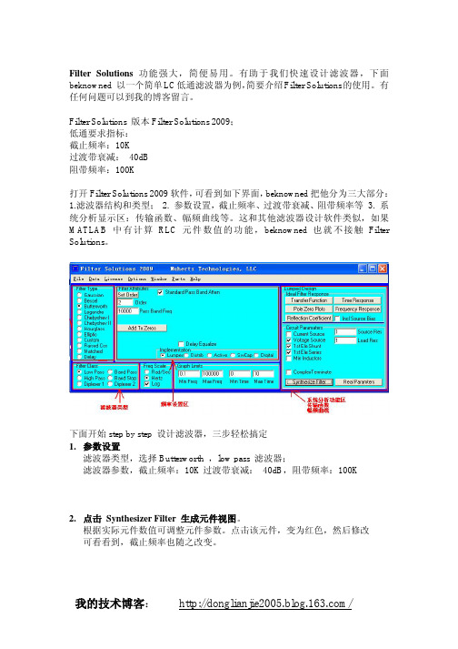
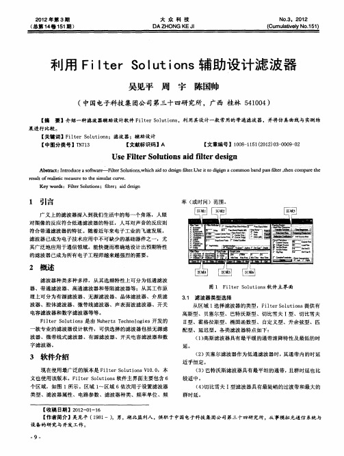
打开Filter Solutions 2009软件,可看到如下界面,beknowned把他分为三大部分:1.滤波器结构和类型;2. 参数设置,截止频率、过渡带衰减、阻带频率等3. 系统分析显示区:传输函数、幅频曲线等。
这和其他滤波器设计软件类似,如果MATLAB中有计算RLC元件数值的功能,beknowned 也就不接触Filter Solutions。
下面开始step by step 设计滤波器,三步轻松搞定
1.参数设置
滤波器类型,选择Butterworth ,low pass 滤波器;
滤波器参数,截止频率:10K过渡带衰减:40dB,阻带频率:100K
2.点击Synthesizer Filter 生成元件视图。
根据实际元件数值可调整元件参数。
点击该元件,变为红色,然后修改
可看看到,截止频率也随之改变。
3. 查看幅频曲线
可以看到以上参数符合设计要求
有问题欢迎探讨,我的技术博客/。
使用Filter Solution设计低通滤波器说明文档
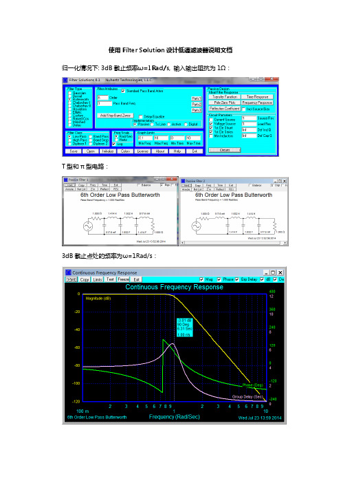
使用 Filter Solution 设计低通滤波器说明文档 归一化情况下: 3dB 截止频率ω=1Rad/s, 输入输出阻抗为 1Ω:
T 型和 π 型电路:
3dB 截止点处的频率为ω=1Rad/s:
பைடு நூலகம்
工作频率为 30MHz, 3dB 截止频率为 38MHz,输入输出阻抗匹配 50Ω:
工作频率为 50MHz,3dB 截止频率为 58MHz,输入输出阻抗匹配 50Ω:
T 型和 π 型电路:
50MHz 处 0.65dB,3dB 截止点处的频率为 58MHz:
40dB 阻带衰减处 125MHz, 60dB 阻带衰减处 184MHz:
40dB 阻带衰减处 94.8MHz, 60dB 阻带衰减处 139MHz:
工作频率为 48MHz, 3dB 截止频率为 56MHz,输入输出阻抗匹配 50Ω:
T 型和 π 型电路:
48MHz 处 0.655dB,3dB 截止点处的频率为 56MHz:
40dB 阻带衰减处 120MHz, 60dB 阻带衰减处 177MHz:
T 型和 π 型电路:
50MHz 处衰减 0.246dB,3dB 截止点处的频率为 58MHz:
40dB 阻带衰减处 82MHz, 60dB 阻带衰减处 120MHz:
工作频率为 36MHz, 3dB 截止频率为 44MHz,输入输出阻抗匹配 50Ω:
T 型和 π 型电路:
36MHz 处衰减 0.377dB,3dB 截止点处的频率为 44MHz:
EMIFILTERSOLUTIONSOVERVIEWEMI滤波器解决方案概述
电磁集成解决方案 (简称:EIS)
电源解决方案
安全系统和信息保 证 (简称:SSIA)
电子制造服务 (简称:EMS)
43%
国防和商业市场的 射频, 微波,毫米波, 和微电子产品
24%
无源元件和射频信 号调节, 免疫, 发射 和磁化; 磁学; 和陶 瓷产品
6%
电源控制, 转换和分 配产品; EOD产品; 和 集成体系
2015
C-MAC 航空航天
1972
成立
2011
RTI 电子
1968
成立
1998 1999
AMP 陶瓷产品 信号调节产品
2002
FSY 微波
2004
Salisbury 工程 REMEC 组件
2005
Amplifonix JDK 控制
2006 2007 2008 2009 2010 2011
高级热量 EMF系统 产品 SatCon 电子 微软 DRS 信号 应对措施 Sage 实验室 最高级仪器
10%
通信保护产品包 含TEMPEST, 坚固, 和安全访问
17%
合同制造和高可 靠性新产品引进 服务
例如: - AESA 雷达模块 - GaN 电源安培
商业分段
SSC
例如: - EMI滤波器 - 圆形的连接器
SSIA EMS
例如: - Tactical 电源 - 电源监控
例如: -安全, 坚固通信中心 - Netgard® 安全访问
C O R P .
WE ARE HIGH –RELIABILITY我们有很高的可靠性
• 主要应用元件,模块,系统和产品。 • 90%多 唯一或主要来源 • 设计和高级设计 • 专注于关键技术增长区域 • 与客户建立长期技术合作关系
Ansys Nuhertz FilterSolutions 说明书

Ansys Nuhertz FilterSolutions Ansys Nuhertz FilterSolutions provides automated design, synthesis and optimization of RF, microwave and digital filters in an efficient and straightforward process. FilterSolutions starts with your filter performance specifications, synthesizes both ideal and physical filter layout realizations and automatically sets up filter analysis and optimization in the Ansys HFSS electromagnetic simulator.•Performing high-performance microwave and mmWave filter design is difficult and requires expertknowledge to synthesize filter layouts.•RF and microwave filters experience electromagnetic (EM) cross coupling, which leads to inaccuracies intraditional circuit modeling approaches. •Poor filter designs and manufacturing tolerances drivethe need for manual filter “tuning” by hand on the bench. A good CAE approach can create tuning free designs that work within manufacturing or material tolerances.•High-order filters are difficult to optimize, even with EM software. Creating an accurate first designprototype is essential for fast design optimization.Open the filter design in AnsysHFSS, ready for immediate EManalysis and optimization.Create digital filters in the form of filter tap coefficients and C-codefunctions./Targeting your top 4 pain points:/Achieving your top 4 tasks:Quickly, easily and automaticallysynthesize a filter that meets yourperformance requirement.Realize the filter design in schematic and physical layouts for your choice of substrates byharnessing vendor-specific partsand standard value components.Filter design in Ansys Nuhertz FilterSolutionsElectromagnetic simulation of synthesized filter in HFSS/W hat differentiates Ansys Nuhertz FilterSolutions? •Performance specification for Layout-to-EM-Optimization in a single smooth workflow•Ability to evaluate the widest range of filter topologies (Bessel, Butterworth, Chebyshev I and II, Elliptic, Gaussian, Delay, Hourglass, Legendre, Matched, Raised Cosine, Tubular, Zigzag, Coupled-Resonator and Cross-Coupled Folded Resonator)•Highly accurate distributed filter layout synthesis based on EM-derived model discontinuities and couplings•Integrates with HFSS for gold-standard EM analysis accuracy and for EM-based optimization•Ability to synthesize filter topologies for analog and digital filter topologies; a single tool for creating accurate filters for both analog and digital signal processing (DSP) applications•Planar filter realizations in the widest available media classes (microstrip, stripline, asymmetric stripline, suspended substrate)/Ansys Nuhertz FilterSolutions provides automatic filter design for: •Lumped filters , presenting synthesized filter schematics that fulfill the filter performance specification. Also provides values for filters realized on PCBs with surface mount or thru-hole discrete components.•Distributed (transmission line filters) - High-performance distributed filters manufactured on microwave or mmWave substrates. These filters are usually realized with transmission lines, open or shorted stubs, vias, coupled lines and cross-coupled transmission line systems. A broad class of microwave and mmWave filters can be realized through precision patterning of conductors on one to three planar substrates.•Digital filters realized in software for digital signal processing (DSP) systems or on microcontrollers. These are software programs, applied to digital signal processing operating on data from digital sampling systems.•Zero-inductor analog filters - Popular at lower frequencies (audio and mid-frequency analog systems), these filters can be realized on PCB process technology with OpAmps in an analog filter format.•IC-based filters in the form of non-programmable digital filters can also be implemented in IC processes utilizing MOSFETS and capacitors to occupy minimum real estate and utilize a switched-capacitor approach.LUMPED (PASSIVE) FILTER MODULE Synthesizes a lumped component filter (single or double-termination) of a selected filter topology to realize user-specified performance characteristics. Standard value components may be applied, with standard (or non-standard) tolerance values for Monte-Carlo analysis. Components have ideal or finite Q or may be based upon vendor component library models.CAPABILITIESDISTRIBUTED FILTER MODULE The Distributed Filter module synthesizes filter layouts on physics-accurate materials, incorporating transmission lines and hybrid lumped elements. Filter layouts can be realized in a variety of substrate formats, including microstrip, suspended substrate and stripline. Physical layouts (including metallization and substrate material properties) can be realized quickly and accurately. Filter layouts are fully parameterized and may be opened in HFSS for immediate EM analysis; all geometries, materials, ports and analysis setups are automatically created. HFSS designs are fully parameterized and optimization setups are provided, so the designer can proceed directly to design optimization to desired response goals.ACTIVE FILTER MODULE Some filter designs call for elimination of inductors and active filter designs with OpAmps can sometimes provide an attractive alternative. The FilterSolutions Active Filter module synthesizes filters to meet user-specified performance requirements in a wide range of filter topologies, such as Thomas, Akerberg-Mossberg, Sallen-Key, Multiple Feedback, Leapfrog, GICs and more. Incorporate OpAmp models from your favorite vendor and include finite Q and gain effects in your active filter designs.SWITCHED-CAPACITOR FILTER MODULEAnother zero-inductor realization: Switched capacitor filters are generally realized in semiconductor processes where capacitors and switching transistors occupy comparatively small spaces. Switched-capacitor filters may be used to realize digital filters and involve sampling circuit topologies. The Switched-Capacitor Filter module synthesizes designs in IIR and FIR realizations, as well as Bilinear, Matched-Z, Step Invariant, Modified Impulse Invariant and custom Z-transform designs.ANSYS, Inc. *******************866.267.9724© 2021 ANSYS, Inc. All Rights Reserved.DISTRIBUTED FILTER DESIGN TOPOLOGIES Lumped Translation, Inductor Translation, Stepped Impedance, Shunt Stub Resonators, Open Stub Resonators, Spaced Stubs, Dual Resonators, Spaced Dual Resonators, Parallel Edge Coupled, Hairpin, Miniature Hairpin, Ring Resonator, Interdigital, ComblineACTIVE FILTER IMPLEMENTATIONS Thomas 1 and 2, Sallen & Key, Parallel, Akerberg, Multiple Feedback (MFB), GIC Biquad, GIC Ladder, Leap FrogDIGITAL FILTER DESIGNS BASED ON THE FOLLOWING DIGITAL TRANSFORMATIONSBilinear, Impulse Invariant (IIR), Matched Z, Step Invariant, FIR Approximation. FIR Filter Types: Rectangular, Bartlett, Hanning, Hamming, Blackman, Blackman-Harris, Kaiser, Dolph-Cheby, Remez, Raised Cosine, Root Raised Cosine, Cosine Filter, Sine Filter, Matched Filter, DelayFilter DIGITAL FILTER MODULE For DSP and sampled systems, FilterSolutions takes user-specified performance specifications and a desired topology and synthesizes filter coefficients to realize the digital filter. Digital transformations are provided to Bilinear, Impulse Invariant, Step Invariant, Matched-Z and Finite Impulse Response (FIR) approximation. Filter realizations are provided in the form of the discrete transfer function, filter tap/block coefficients or as C-code ready for incorporation into a DSP code block.ZMATCH MODULE Zmatch starts with complex load definitions and synthesizes a matching network for maximum power transfer. Includes both Discrete Frequency and Broadband Match modes. Optimal matching networks are provided in lumped, distributed and hybrid realizations.FILTER TYPES AVAILABLE (LUMPED AND DISTRIBUTED FILTERS)Gaussian, Bessel, Butterworth, Legendre, Chebyshev (I and II), Hourglass, Elliptic, Raised Cosine, Matched, Delay FILTER CLASSES AVAILABLE (LUMPED AND DISTRIBUTED FILTERS)Lumped Translation, Inductor Translation, Stepped Impedance, Shunt Stub Resonators, Open Stub Resonators, Spaced Stubs, Dual Resonators, Spaced Dual Resonators, Parallel Edge Coupled, Hairpin, Miniature Hairpin, Ring Resonator, Interdigital, Combline。
Filter Solutions滤波器设计教程
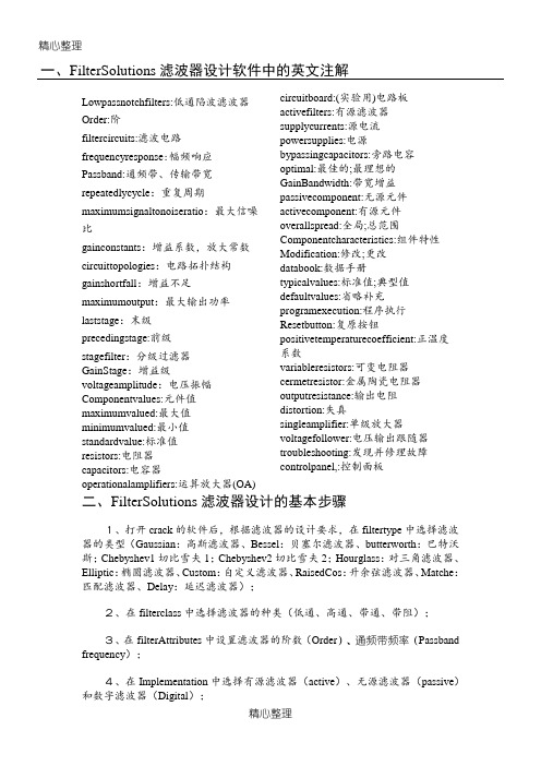
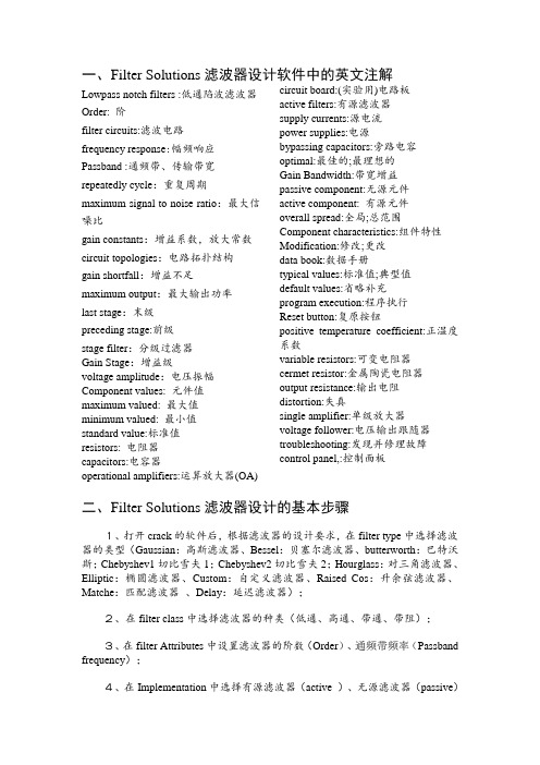
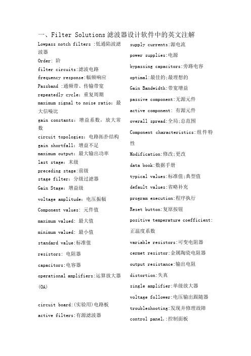
精心整理一、FilterSolutions 滤波器设计软件中的英文注解Lowpassnotchfilters:低通陷波滤波器 Order:阶filtercircuits:滤波电路 frequencyresponse :幅频响应 Passband:通频带、传输带宽 repeatedlycycle :重复周期maximumsignaltonoiseratio :最大信噪circuitboard:(实验用)电路板 activefilters:有源滤波器 supplycurrents:源电流 powersupplies:电源bypassingcapacitors:旁路电容 optimal:最佳的;最理想的 GainBandwidth:带宽增益 passivecomponent:无源元件 斯;Chebyshev1切比雪夫1;Chebyshev2切比雪夫2;Hourglass :对三角滤波器、Elliptic :椭圆滤波器、Custom :自定义滤波器、RaisedCos :升余弦滤波器、Matche :匹配滤波器、Delay :延迟滤波器);2、在filterclass 中选择滤波器的种类(低通、高通、带通、带阻); 3、在filterAttributes 中设置滤波器的阶数(Order )、通频带频率(Passband frequency );4、在Implementation 中选择有源滤波器(active )、无源滤波器(passive )和数字滤波器(Digital );5、在FreqScale中选择Hertz和Log,如果选择了Rad/Sec,则要注意Rad/Sec =6.28*Hertz;6、在GraphLimits中设置好图像的最大频率和最小频率,最大频率要大于通频带的截止频率;在PassiveDesign/IdealFilterResponse中观察传输函数(TransferFunction)、时域响应(TimeResponse)、零极点图(PoleZeroPlots)、频域响应(FrequencyResponse)的图像;7、在CircuitParmaters中设置源电阻(SourceRes)和负载电阻(LoadRes);最后点击Circuits观察滤波器电路图;70M/77.31M=1.104;当选择Freq(频率)时,StopBandAtten(阻带衰减)应该选择77.31M.6、在GraphLimits中设置好图像的最大频率和最小频率,最大频率要大于通频带的截止频率我们设置为100M;在PassiveDesign/IdealFilterResponse中观察传输函数(TransferFunction)、时域响应(TimeResponse)、零极点图(PoleZeroPlots)、频域响应(FrequencyResponse)的图像;7、在CircuitParmaters中设置源电阻(SourceRes)我们设为200欧和负载电阻(LoadRes)我们同样设为200欧;最后点击Circuits观察滤波器电路图;点击TransferFunction查看传递函数:点击TimeResponse查看响应曲线。
Filter Solutions滤波器设计教程

一、FilterSolutions滤波器设计软件中的英文注解Lowpassnotchfilters:低通陷波滤波器Order:阶filtercircuits:滤波电路frequencyresponse:幅频响应Passband:通频带、传输带宽repeatedlycycle:重复周期maximumsignaltonoiseratio:最大信噪比gainconstants:增益系数,放大常数circuittopologies:电路拓扑结构gainshortfall:增益不足maximumoutput:最大输出功率laststage:末级precedingstage:前级stagefilter:分级过滤器GainStage:增益级voltageamplitude:电压振幅Componentvalues:元件值maximumvalued:最大值minimumvalued:最小值standardvalue:标准值resistors:电阻器capacitors:电容器operationalamplifiers:运算放大器(OA) circuitboard:(实验用)电路板activefilters:有源滤波器supplycurrents:源电流powersupplies:电源bypassingcapacitors:旁路电容optimal:最佳的;最理想的GainBandwidth:带宽增益passivecomponent:无源元件activecomponent:有源元件overallspread:全局;总范围Componentcharacteristics:组件特性Modification:修改;更改databook:数据手册typicalvalues:标准值;典型值defaultvalues:省略补充programexecution:程序执行Resetbutton:复原按钮positivetemperaturecoefficient:正温度系数variableresistors:可变电阻器cermetresistor:金属陶瓷电阻器outputresistance:输出电阻distortion:失真singleamplifier:单级放大器voltagefollower:电压输出跟随器troubleshooting:发现并修理故障controlpanel,:控制面板二、FilterSolutions滤波器设计的基本步骤1、打开crack的软件后,根据滤波器的设计要求,在filtertype中选择滤波器的类型(Gaussian:高斯滤波器、Bessel:贝塞尔滤波器、butterworth:巴特沃斯;Chebyshev1切比雪夫1;Chebyshev2切比雪夫2;Hourglass:对三角滤波器、Elliptic:椭圆滤波器、Custom:自定义滤波器、RaisedCos:升余弦滤波器、Matche:匹配滤波器、Delay:延迟滤波器);2、在filterclass中选择滤波器的种类(低通、高通、带通、带阻);3、在filterAttributes中设置滤波器的阶数(Order)、通频带频率(Passband frequency);4、在Implementation中选择有源滤波器(active)、无源滤波器(passive)和数字滤波器(Digital);5、在FreqScale中选择Hertz和Log,如果选择了Rad/Sec,则要注意Rad/Sec =6.28*Hertz;6、在GraphLimits中设置好图像的最大频率和最小频率,最大频率要大于通频带的截止频率;在PassiveDesign/IdealFilterResponse中观察传输函数(TransferFunction)、时域响应(TimeResponse)、零极点图(PoleZeroPlots)、频域响应(FrequencyResponse)的图像;7、在CircuitParmaters中设置源电阻(SourceRes)和负载电阻(LoadRes);最后点击Circuits观察滤波器电路图;8、在设计有缘滤波器的时候还要注意在ActiveImplementation中选择滤波器的电路布局形式一般有源滤波器选择PosSAB型的,在CircuitParmaters中设置增益大小(gain)。
filters的使用

Filters的使用概述*f i l t e r s在计算机科学领域,*(过滤器)是一种常用的数据处理工具,用于从原始数据中提取所需信息或对数据进行转换。
在本文中,我们将详细探讨f il te rs的使用,并介绍一些常见的fi lt er类型和应用场景。
1.什么是f ilters?F i lt er s是一种用于处理和转换数据的技术。
它们可以应用于多种数据类型,包括文本、数字、图像等。
F ilt e rs基于特定规则操作输入数据,根据这些规则选择性地提取、修改或删除数据。
通过使用fi lt er s,我们可以实现数据的筛选、格式转换、数据清洗以及数据提取等功能。
2. Fi lter的类型根据不同的数据类型和处理需求,我们可以使用各种类型的f i lt er s。
以下是一些常见的fi l te r类型:2.1文本过滤器文本过滤器用于处理文本数据,常见的应用场景包括过滤敏感词汇、自动纠正拼写错误、分词等。
通过使用文本过滤器,我们可以有效地处理大量的文本数据,实现文本智能化处理和分析。
2.2数值过滤器数值过滤器用于对数字数据进行处理和转换。
它可以应用于统计分析、数据清洗、异常检测等领域。
数值过滤器可以通过一系列算法和规则实现数据的筛选、归一化、平滑处理等功能。
2.3图像过滤器图像过滤器是一种特殊的fi lt er类型,用于处理图像数据。
它可以应用于图像增强、去噪、边缘检测等图像处理任务中。
图像过滤器基于像素的操作,采用不同的算法对图像进行处理,以改善图像的质量或提取其中的特定特征。
3. Fi lter的应用场景F i lt er s广泛应用于各个领域,以下是几个常见的应用场景:3.1垃圾邮件过滤随着电子邮件的普及,垃圾邮件的问题日益严重。
通过使用垃圾邮件过滤器,可以识别垃圾邮件并将其自动分类到垃圾邮件文件夹,从而提高邮件的处理效率。
3.2金融风险检测在金融领域,对于风险的快速识别和响应至关重要。
通过使用f i lt er s,可以实现对金融数据的实时监测,提取异常数据并通过预设规则识别潜在的风险因素。
filter solutions 设计滤波器笔记总结

用Filter solutions设计滤波器笔记要求:分别设计5阶切比雪夫1型带通滤波器、切比雪夫2型带通滤波器,中心频率500MHz,带宽50MHz。
尝试选用不同的电路结构,观察所用元器件的值有何变化。
切比雪夫1型滤波器:通带中等纹波,阻带是单调的切比雪夫2型滤波器:通带中单调,阻带等纹波,即阻带中有零点(陷波点)。
(1)5阶切比雪夫1型带通滤波器:通带中等纹波,阻带是单调的图1:参数设置注释:Asymmetrical非对称的,只有带通滤波器才有此选项,用于设计非对称结构的滤波器。
Delay Equalize延迟补偿,低通和带通滤波器才有此选项,用于低通滤波器或者带通滤波器的通带群延迟补偿。
延迟补偿的概念:Tx Line:Transmission Line 传输线滤波器Sw Cap:Switched Capacitor开关电容滤波器,Active:有源滤波器,Passive:无源滤波器,Digital:数字滤波器,1st Ele Shunt:滤波器电路结构的第一个元件是并联电感。
1st Ele Series:滤波器电路的第一个元件是串联电容。
Incl Source Bias:Check to include the bias due to the source resistance to appear in the transfer function, frequency response, impedance response, and time response of your filter. For example, if the source resistance is equal to the load resistance, checking this box will cause a -6dB offset will appear in the frequency response, and a factor of .5 will appear in the transfer function and time response. This offset goes away when this box is left unchecked.This box should be left unchecked when using the transfer function for any purpose other than passive filters applications.Complex Terminations:创建滤波器复杂的驱动终端,即自定义滤波器的源终端。
filter函数命令
filter函数命令摘要:filter函数命令的概述与使用方法一、filter函数的定义与作用1.函数定义2.功能概述二、filter函数的参数与用法1.参数详解2.函数用法示例三、filter函数的应用场景1.过滤列表中的特定元素2.数据清洗与处理四、filter函数的优缺点1.优点2.缺点五、filter函数的替代方法1.使用列表推导式2.使用生成器表达式正文:filter函数是Python内置的高阶函数,用于过滤序列。
它可以接收一个函数和一个序列作为参数,将函数作用于序列的每个元素,然后根据函数返回值是True还是False决定是否保留该元素。
filter函数返回一个新的可迭代对象,其中包含序列中使函数返回True的元素。
一、filter函数的定义与作用1.函数定义:filter(function, iterable)2.功能概述:接收一个函数和一个可迭代对象,返回一个新的可迭代对象,其中包含使函数返回True的元素。
二、filter函数的参数与用法1.参数详解:- function:一个函数,用于判断序列中的元素是否满足条件。
- iterable:一个可迭代对象,如列表、元组等。
2.函数用法示例:```pythondef is_even(x):return x % 2 == 0umbers = [1, 2, 3, 4, 5, 6, 7, 8, 9]result = filter(is_even, numbers)print(list(result)) # 输出:[2, 4, 6, 8]```三、filter函数的应用场景1.过滤列表中的特定元素:如筛选出列表中的偶数、奇数等。
2.数据清洗与处理:在进行数据分析时,可以使用filter函数对数据进行预处理,如去除空值、异常值等。
四、filter函数的优缺点1.优点:- 简洁明了的语法,易于阅读和编写。
- 可以方便地对序列进行过滤操作,提高代码可读性。
filter_solutions教程
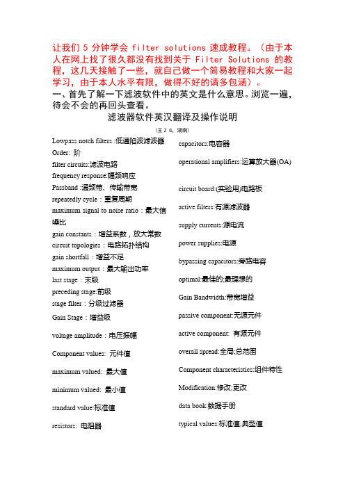
让我们5分钟学会filter solutions速成教程。
(由于本人在网上找了很久都没有找到关于Filter Solutions的教程,这几天接触了一些,就自己做一个简易教程和大家一起学习,由于本人水平有限,做得不好的请多包涵)。
一、首先了解一下滤波软件中的英文是什么意思。
浏览一遍,待会不会的再回头查看。
滤波器软件英汉翻译及操作说明(王Z G,湖南)Lowpass notch filters :低通陷波滤波器Order: 阶filter circuits:滤波电路frequency response:幅频响应Passband :通频带、传输带宽repeatedly cycle:重复周期maximum signal to noise ratio:最大信噪比gain constants:增益系数,放大常数circuit topologies:电路拓扑结构gain shortfall:增益不足maximum output:最大输出功率last stage:末级preceding stage:前级stage filter:分级过滤器Gain Stage:增益级voltage amplitude:电压振幅Component values: 元件值maximum valued: 最大值minimum valued: 最小值standard value:标准值resistors: 电阻器capacitors:电容器operational amplifiers:运算放大器(OA) circuit board:(实验用)电路板active filters:有源滤波器supply currents:源电流power supplies:电源bypassing capacitors:旁路电容optimal:最佳的;最理想的Gain Bandwidth:带宽增益passive component:无源元件active component: 有源元件overall spread:全局;总范围Component characteristics:组件特性Modification:修改;更改data book:数据手册typical values:标准值;典型值default values:省略补充program execution:程序执行Reset button:复原按钮positive temperature coefficient:正温度系数variable resistors:可变电阻器cermet resistor:金属陶瓷电阻器output resistance:输出电阻distortion:失真single amplifier:单级放大器voltage follower:电压输出跟随器troubleshooting:发现并修理故障control panel,:控制面板二、让我们来看看滤波器设计的基本步骤1、打开crack的软件后,根据滤波器的设计要求,在filter type中选择滤波器的类型(Gaussian:高斯滤波器、Bessel:贝塞尔滤波器、butterworth:巴特沃斯;Chebyshev1切比雪夫1;Chebyshev2切比雪夫2;Hourglass:对三角滤波器、Elliptic:椭圆滤波器、Custom:自定义滤波器、Raised Cos:升余弦滤波器、Matche:匹配滤波器、Delay:延迟滤波器);2、在filter class中选择滤波器的种类(低通、高通、带通、带阻);3、在filter Attributes中设置滤波器的阶数(Order)、通频带频率(Passband frequency);4、在Implementation中选择有源滤波器(active )、无源滤波器(passive)和数字滤波器(Digital);5、在Freq Scale中选择Hertz和Log,如果选择了Rad/Sec,则要注意Rad/Sec =6.28*Hertz;6、在Graph Limits中设置好图像的最大频率和最小频率,最大频率要大于通频带的截止频率;在Passive Design/Ideal Filter Response中观察传输函数(Transfer Function)、时域响应(Time Response)、零极点图(Pole Zero Plots)、频域响应(Frequency Response)的图像;7、在Circuit Parmaters中设置源电阻(Source Res)和负载电阻(Load Res);最后点击Circuits观察滤波器电路图;8、在设计有缘滤波器的时候还要注意在Active Implementation 中选择滤波器的电路布局形式一般有源滤波器选择Pos SAB型的,在Circuit Parmaters中设置增益大小(gain)。
filtersolution 2020

2020年,各行各业都在面临前所未有的挑战和变革。
在这样的背景下,人们对于解决问题和应对挑战的需求也变得更加迫切。
而作为一个解决方案,filtersolution逐渐成为了人们关注和探讨的焦点之一。
在本文中,我们将深入探讨filtersolution在2020年的发展和应用,并从多个角度分析其意义和影响。
1. filtersolution的概念和意义让我们明确filtersolution的概念和意义。
filtersolution指的是一种过滤解决方案,它可以帮助人们从复杂的信息和数据中筛选出真正有价值的部分。
在当下信息爆炸的时代,人们面临着海量的信息和数据,如何高效地获取并利用这些信息成为了一个急需解决的问题。
而filtersolution的出现,为人们提供了一种全新的思路和方法,帮助他们更加聚焦地获取所需信息,从而更加高效地解决问题和应对挑战。
2. filtersolution的发展现状在2020年, filtersolution在各个领域得到了广泛的应用和发展。
在互联网行业,随着信息量的不断增加,各大评台纷纷推出了基于filtersolution的智能推荐系统,帮助用户根据个性化的需求获取更有价值的信息。
而在企业管理领域,越来越多的公司开始引入filtersolution来优化业务流程和提高效率。
在金融、医疗、教育等行业,filtersolution也得到了广泛的应用,为各个行业的发展注入了新的活力。
3. filtersolution的个人观点和理解从个人的角度来看,我认为filtersolution作为一种解决方案,能够为人们的生活和工作带来更多的便利和效率。
在信息爆炸的背景下,我们往往会被大量的信息所淹没,很难从中找到真正有价值的部分。
而拥有一个优秀的filtersolution,可以帮助我们过滤掉大部分无用的信息,从而更加聚焦地获取所需的信息和数据。
这对于个人的学习、工作和生活都具有重要的意义。
Filter Solutions滤波器设计教程汇总
一、Filter Solutions滤波器设计软件中的英文注解Lowpass notch filters :低通陷波滤波器Order: 阶filter circuits:滤波电路frequency response:幅频响应Passband :通频带、传输带宽repeatedly cycle:重复周期maximum signal to noise ratio:最大信噪比gain constants:增益系数,放大常数circuit topologies:电路拓扑结构gain shortfall:增益不足maximum output:最大输出功率last stage:末级preceding stage:前级stage filter:分级过滤器Gain Stage:增益级voltage amplitude:电压振幅Component values: 元件值maximum valued: 最大值minimum valued: 最小值standard value:标准值resistors: 电阻器capacitors:电容器operational amplifiers:运算放大器(OA) circuit board:(实验用)电路板active filters:有源滤波器supply currents:源电流power supplies:电源bypassing capacitors:旁路电容optimal:最佳的;最理想的Gain Bandwidth:带宽增益passive component:无源元件active component: 有源元件overall spread:全局;总范围Component characteristics:组件特性Modification:修改;更改data book:数据手册typical values:标准值;典型值default values:省略补充program execution:程序执行Reset button:复原按钮positive temperature coefficient:正温度系数variable resistors:可变电阻器cermet resistor:金属陶瓷电阻器output resistance:输出电阻distortion:失真single amplifier:单级放大器voltage follower:电压输出跟随器troubleshooting:发现并修理故障control panel,:控制面板二、Filter Solutions滤波器设计的基本步骤1、打开crack的软件后,根据滤波器的设计要求,在filter type中选择滤波器的类型(Gaussian:高斯滤波器、Bessel:贝塞尔滤波器、butterworth:巴特沃斯;Chebyshev1切比雪夫1;Chebyshev2切比雪夫2;Hourglass:对三角滤波器、Elliptic:椭圆滤波器、Custom:自定义滤波器、Raised Cos:升余弦滤波器、Matche:匹配滤波器、Delay:延迟滤波器);2、在filter class中选择滤波器的种类(低通、高通、带通、带阻);3、在filter Attributes中设置滤波器的阶数(Order)、通频带频率(Passband frequency);4、在Implementation中选择有源滤波器(active )、无源滤波器(passive)和数字滤波器(Digital);5、在Freq Scale中选择Hertz和Log,如果选择了Rad/Sec,则要注意Rad/Sec =6.28*Hertz;6、在Graph Limits中设置好图像的最大频率和最小频率,最大频率要大于通频带的截止频率;在Passive Design/Ideal Filter Response中观察传输函数(Transfer Function)、时域响应(Time Response)、零极点图(Pole Zero Plots)、频域响应(Frequency Response)的图像;7、在Circuit Parmaters中设置源电阻(Source Res)和负载电阻(Load Res);最后点击Circuits观察滤波器电路图;8、在设计有缘滤波器的时候还要注意在Active Implementation 中选择滤波器的电路布局形式一般有源滤波器选择Pos SAB型的,在Circuit Parmaters中设置增益大小(gain)。
Filter-Solutions10教程
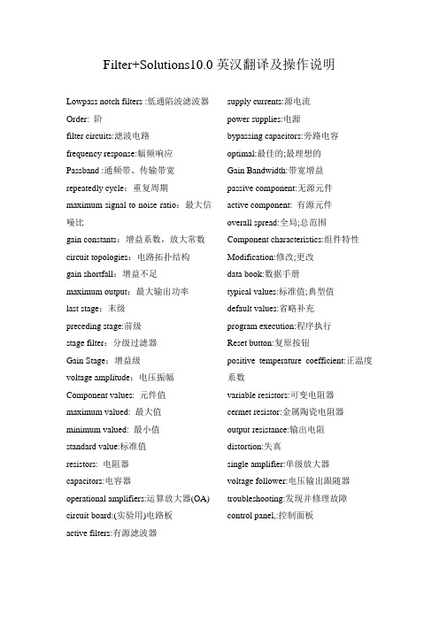
Filter+Solutions10.0英汉翻译及操作说明Lowpass notch filters :低通陷波滤波器Order: 阶filter circuits:滤波电路frequency response:幅频响应Passband :通频带、传输带宽repeatedly cycle:重复周期maximum signal to noise ratio:最大信噪比gain constants:增益系数,放大常数circuit topologies:电路拓扑结构gain shortfall:增益不足maximum output:最大输出功率last stage:末级preceding stage:前级stage filter:分级过滤器Gain Stage:增益级voltage amplitude:电压振幅Component values: 元件值maximum valued: 最大值minimum valued: 最小值standard value:标准值resistors: 电阻器capacitors:电容器operational amplifiers:运算放大器(OA) circuit board:(实验用)电路板active filters:有源滤波器supply currents:源电流power supplies:电源bypassing capacitors:旁路电容optimal:最佳的;最理想的Gain Bandwidth:带宽增益passive component:无源元件active component: 有源元件overall spread:全局;总范围Component characteristics:组件特性Modification:修改;更改data book:数据手册typical values:标准值;典型值default values:省略补充program execution:程序执行Reset button:复原按钮positive temperature coefficient:正温度系数variable resistors:可变电阻器cermet resistor:金属陶瓷电阻器output resistance:输出电阻distortion:失真single amplifier:单级放大器voltage follower:电压输出跟随器troubleshooting:发现并修理故障control panel,:控制面板1、打开crack的软件后,根据滤波器的设计要求,在filter type中选择滤波器的类型(Gaussian:高斯滤波器、Bessel:贝塞尔滤波器、butterworth:巴特沃斯;Chebyshev1切比雪夫1;Chebyshev2切比雪夫2;Hourglass:对三角滤波器、Elliptic:椭圆滤波器、Custom:自定义滤波器、Raised Cos:升余弦滤波器、Matche:匹配滤波器、Delay:延迟滤波器);2、在filter class中选择滤波器的种类(低通、高通、带通、带阻);3、在filter Attributes中设置滤波器的阶数(Order)、通频带频率(Passband frequency);4、在Implementation中选择有源滤波器(active )、无源滤波器(passive)和数字滤波器(Digital);5、在Freq Scale中选择Hertz和Log,如果选择了Rad/Sec,则要注意Rad/Sec =6.28*Hertz;6、在Graph Limits中设置好图像的最大频率和最小频率,最大频率要大于通频带的截止频率;在Passive Design/Ideal Filter Response中观察传输函数(Transfer Function)、时域响应(Time Response)、零极点图(Pole Zero Plots)、频域响应(Frequency Response)的图像;7、在Circuit Parmaters中设置源电阻(Source Res)和负载电阻(Load Res);最后点击Circuits观察滤波器电路图;8、在设计有缘滤波器的时候还要注意在Active Implementation 中选择滤波器的电路布局形式一般有源滤波器选择Pos SAB型的,在Circuit Parmaters中设置增益大小(gain)。
Filter Solutions 教程

用Filter solutions设计滤波器笔记要求:分别设计5阶切比雪夫1型带通滤波器、切比雪夫2型带通滤波器,中心频率500MHz,带宽50MHz。
尝试选用不同的电路结构,观察所用元器件的值有何变化。
切比雪夫1型滤波器:通带中等纹波,阻带是单调的切比雪夫2型滤波器:通带中单调,阻带等纹波,即阻带中有零点(陷波点)。
(1)5阶切比雪夫1型带通滤波器:通带中等纹波,阻带是单调的图1:参数设置注释:Asymmetrical非对称的,只有带通滤波器才有此选项,用于设计非对称结构的滤波器。
Delay Equalize延迟补偿,低通和带通滤波器才有此选项,用于低通滤波器或者带通滤波器的通带群延迟补偿。
延迟补偿的概念:Tx Line:Transmission Line 传输线滤波器Sw Cap:Switched Capacitor开关电容滤波器,Active:有源滤波器,Passive:无源滤波器,Digital:数字滤波器,1st Ele Shunt:滤波器电路结构的第一个元件是并联电感。
1st Ele Series:滤波器电路的第一个元件是串联电容。
Incl Source Bias:Check to include the bias due to the source resistance to appear in the transfer function, frequency response, impedance response, and time response of your filter. For example, if the source resistance is equal to the load resistance, checking this box will cause a -6dB offset will appear in the frequency response, and a factor of .5 will appear in the transfer function and time response. This offset goes away when this box is left unchecked.This box should be left unchecked when using the transfer function for any purpose other than passive filters applications.Complex Terminations:创建滤波器复杂的驱动终端,即自定义滤波器的源终端。
filter_solutions教程
让我们5分钟学会filter solutions速成教程。
(由于本人在网上找了很久都没有找到关于Filter Solutions的教程,这几天接触了一些,就自己做一个简易教程和大家一起学习,由于本人水平有限,做得不好的请多包涵)。
一、首先了解一下滤波软件中的英文是什么意思。
浏览一遍,待会不会的再回头查看。
滤波器软件英汉翻译及操作说明(王Z G,湖南)Lowpass notch filters :低通陷波滤波器Order: 阶filter circuits:滤波电路frequency response:幅频响应Passband :通频带、传输带宽repeatedly cycle:重复周期maximum signal to noise ratio:最大信噪比gain constants:增益系数,放大常数circuit topologies:电路拓扑结构gain shortfall:增益不足maximum output:最大输出功率last stage:末级preceding stage:前级stage filter:分级过滤器Gain Stage:增益级voltage amplitude:电压振幅Component values: 元件值maximum valued: 最大值minimum valued: 最小值standard value:标准值resistors: 电阻器capacitors:电容器operational amplifiers:运算放大器(OA) circuit board:(实验用)电路板active filters:有源滤波器supply currents:源电流power supplies:电源bypassing capacitors:旁路电容optimal:最佳的;最理想的Gain Bandwidth:带宽增益passive component:无源元件active component: 有源元件overall spread:全局;总范围Component characteristics:组件特性Modification:修改;更改data book:数据手册typical values:标准值;典型值default values:省略补充program execution:程序执行Reset button:复原按钮positive temperature coefficient:正温度系数variable resistors:可变电阻器cermet resistor:金属陶瓷电阻器output resistance:输出电阻distortion:失真single amplifier:单级放大器voltage follower:电压输出跟随器troubleshooting:发现并修理故障control panel,:控制面板二、让我们来看看滤波器设计的基本步骤1、打开crack的软件后,根据滤波器的设计要求,在filter type中选择滤波器的类型(Gaussian:高斯滤波器、Bessel:贝塞尔滤波器、butterworth:巴特沃斯;Chebyshev1切比雪夫1;Chebyshev2切比雪夫2;Hourglass:对三角滤波器、Elliptic:椭圆滤波器、Custom:自定义滤波器、Raised Cos:升余弦滤波器、Matche:匹配滤波器、Delay:延迟滤波器);2、在filter class中选择滤波器的种类(低通、高通、带通、带阻);3、在filter Attributes中设置滤波器的阶数(Order)、通频带频率(Passband frequency);4、在Implementation中选择有源滤波器(active )、无源滤波器(passive)和数字滤波器(Digital);5、在Freq Scale中选择Hertz和Log,如果选择了Rad/Sec,则要注意Rad/Sec =6.28*Hertz;6、在Graph Limits中设置好图像的最大频率和最小频率,最大频率要大于通频带的截止频率;在Passive Design/Ideal Filter Response中观察传输函数(Transfer Function)、时域响应(Time Response)、零极点图(Pole Zero Plots)、频域响应(Frequency Response)的图像;7、在Circuit Parmaters中设置源电阻(Source Res)和负载电阻(Load Res);最后点击Circuits观察滤波器电路图;8、在设计有缘滤波器的时候还要注意在Active Implementation 中选择滤波器的电路布局形式一般有源滤波器选择Pos SAB型的,在Circuit Parmaters中设置增益大小(gain)。
利用Filter Solutions辅助设计滤波器
【 关键 词】F l e ou in ;滤波器 ;辅 助设计 it r S l t o s
【 中图分类号 】T 7 3 N 1 【 文献标识码 】A 【 文章编号 】10 — 1 12 1) 3 0 0 — 2 0 8 15 (0 2 0 — 0 9 0
Us i e o u i n i l rd sg eF l rS l t sa d f电路设计与仿真 . 在 F le o u i n 主界面中进行如下设置:滤波 器类 i t r l to s S 型为椭圆 函数滤波器 ,滤波器种类为带通滤波 器,阶数 为 5 阶 ,通带上 、下限截止频率分别为 1 OⅡ 、4 0 t ,通带衰 l ̄ z 4  ̄ z { 减 3 B 通带波纹 0 5B 阻带比率为 1 1 信号源为 电压源, d, .d , ., 首个元件并联 , 阻抗为 5 Q,负载阻抗为 5 Q,默认 电容 源 O 0 器 Q值为无穷大,默认 电感器 Q值为无穷大。如 图 1 所示 。 设置完毕后查看电路, F l e o u in 给 出的电路 将 i t rS l t o s
21 0 2年第 3期 ( 总第 1 卷 1 1 ) 4 5 期
大 众 科 技
DA ZHONG KE J
No. 2 1 3。 0 2
Cu l ie o1 1 mua v l N .5 ) t y
利 用 F le o n 辅 助 设 计 滤 波 器 -t S t r I i s u o
( ) 斯 滤波 器 具有 最 平 缓 的通 带滚 降特 性及 最低 的 时 1高
延。
波器、腔体滤波器 、微带线滤波器、声表面波滤波器、开关 电容滤波器和数字滤波器等等。
Fle ouin i tr S l to s是 由 N h r z T c n l g e u e t e h o o i s开 发 的
filter 使用方法
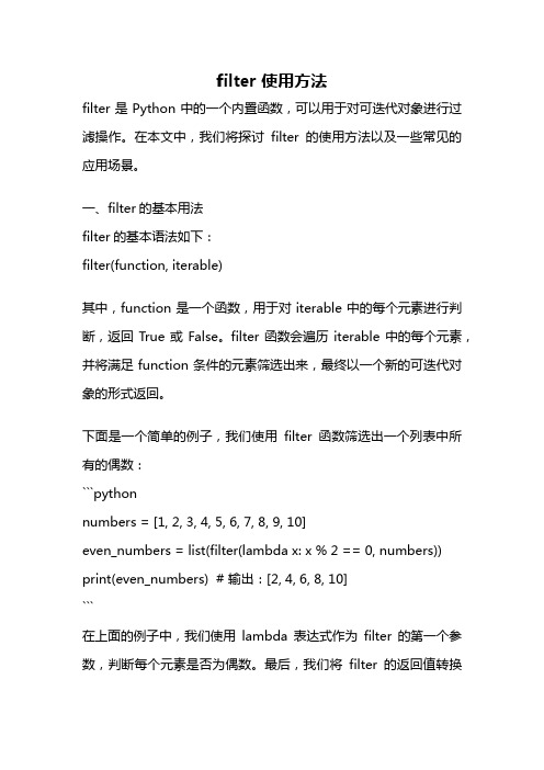
filter 使用方法filter是Python中的一个内置函数,可以用于对可迭代对象进行过滤操作。
在本文中,我们将探讨filter的使用方法以及一些常见的应用场景。
一、filter的基本用法filter的基本语法如下:filter(function, iterable)其中,function是一个函数,用于对iterable中的每个元素进行判断,返回True或False。
filter函数会遍历iterable中的每个元素,并将满足function条件的元素筛选出来,最终以一个新的可迭代对象的形式返回。
下面是一个简单的例子,我们使用filter函数筛选出一个列表中所有的偶数:```pythonnumbers = [1, 2, 3, 4, 5, 6, 7, 8, 9, 10]even_numbers = list(filter(lambda x: x % 2 == 0, numbers)) print(even_numbers) # 输出:[2, 4, 6, 8, 10]```在上面的例子中,我们使用lambda表达式作为filter的第一个参数,判断每个元素是否为偶数。
最后,我们将filter的返回值转换为列表并输出。
二、filter的高级用法除了基本的用法外,filter还可以结合其他函数或技巧实现更复杂的筛选和过滤操作。
1. 结合map函数map函数可以对可迭代对象中的每个元素进行映射操作,将每个元素应用到一个函数中并返回新的可迭代对象。
我们可以将filter和map结合起来,实现对可迭代对象进行筛选和映射的操作。
下面的例子中,我们筛选出一个列表中大于5的偶数,并将它们加倍:```pythonnumbers = [1, 2, 3, 4, 5, 6, 7, 8, 9, 10]result = list(map(lambda x: x * 2, filter(lambda x: x % 2 == 0 and x > 5, numbers)))print(result) # 输出:[12, 16, 20]```在上面的例子中,我们首先使用filter函数筛选出大于5的偶数,然后再使用map函数将每个元素加倍,最后将结果转换为列表并输出。
filtersolutions滤波器设计教程
一、Filter Solutions滤波器设计软件中的英文注解Lowpass notch filters :低通陷波滤波器Order: 阶filter circuits:滤波电路frequency response:幅频响应Passband :通频带、传输带宽repeatedly cycle:重复周期maximum signal to noise ratio:最大信噪比gain constants:增益系数,放大常数circuit topologies:电路拓扑结构gain shortfall:增益不足maximum output:最大输出功率last stage:末级preceding stage:前级stage filter:分级过滤器Gain Stage:增益级voltage amplitude:电压振幅Component values: 元件值maximum valued: 最大值minimum valued: 最小值standard value:标准值resistors: 电阻器capacitors:电容器operational amplifiers:运算放大器(OA)circuit board:(实验用)电路板active filters:有源滤波器supply currents:源电流power supplies:电源bypassing capacitors:旁路电容optimal:最佳的;最理想的Gain Bandwidth:带宽增益passive component:无源元件active component: 有源元件overall spread:全局;总范围Component characteristics:组件特性Modification:修改;更改data book:数据手册typical values:标准值;典型值default values:省略补充program execution:程序执行Reset button:复原按钮positive temperature coefficient:正温度系数variable resistors:可变电阻器cermet resistor:金属陶瓷电阻器output resistance:输出电阻distortion:失真single amplifier:单级放大器voltage follower:电压输出跟随器troubleshooting:发现并修理故障control panel,:控制面板二、Filter Solutions滤波器设计的基本步骤1、打开crack的软件后,根据滤波器的设计要求,在filter type中选择滤波器的类型(Gaussian:高斯滤波器、Bessel:贝塞尔滤波器、butterworth:巴特沃斯;Chebyshev1切比雪夫1;Chebyshev2切比雪夫2;Hourglass:对三角滤波器、Elliptic:椭圆滤波器、Custom:自定义滤波器、Raised Cos:升余弦滤波器、Matche:匹配滤波器、Delay:延迟滤波器);2、在filter class中选择滤波器的种类(低通、高通、带通、带阻);3、在filter Attributes中设置滤波器的阶数(Order)、通频带频率(Passband frequency);4、在Implementation中选择有源滤波器(active )、无源滤波器(passive)和数字滤波器(Digital);5、在Freq Scale中选择Hertz和Log,如果选择了Rad/Sec,则要注意Rad/Sec=*Hertz;6、在Graph Limits中设置好图像的最大频率和最小频率,最大频率要大于通频带的截止频率;在Passive Design/Ideal Filter Response中观察传输函数(Transfer Function)、时域响应(Time Response)、零极点图(Pole Zero Plots)、频域响应(Frequency Response)的图像;7、在Circuit Parmaters中设置源电阻(Source Res)和负载电阻(Load Res);最后点击Circuits观察滤波器电路图;8、在设计有缘滤波器的时候还要注意在Active Implementation 中选择滤波器的电路布局形式一般有源滤波器选择Pos SAB型的,在Circuit Parmaters 中设置增益大小(gain)。