Cisco PPPoE配置实例
Cisco PPPoE Server和Cisco PPPoE Client
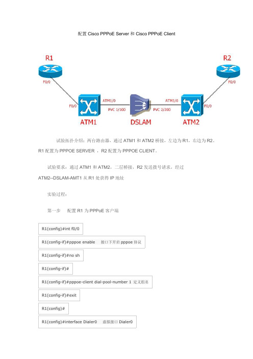
第五步
在 R1 上进行 PPPoE 和 PPP 信息的调试
R1#debug ppp authentication PPP authentication debugging is on R1#debug pppoe events PPPoE protocol events debugging is on R1# *Jun 16 20:35:37.319: *Jun 16 20:35:37.319: R1# padi timer expired Sending PADI: Interface = FastEthernet0/0
R1(config-if)#dialer pool 1 R1(config-if)#ppp chap hostname cisco 度 配置拨号上去加密方式和密钥 0 代表为加密强
R1(config-if)#ppp chap password 0 cisco R1(cห้องสมุดไป่ตู้nfig-if)#exit R1(config)# R1(config)#ip route 0.0.0.0 0.0.0.0 Dialer0 指定一条默认路由,下一跳为 dialer0
第四步
配置 ATM2
ATM2(config)#no ip routing ATM2(config)# ATM2(config)#int f0/0 ATM2(config-if)#no ip add
ATM2(config-if)#no sh ATM2(config-if)#bridge-group 1 ATM2(config-if)# ATM2(config-if)#int atm1/0 ATM2(config-if)#no ip add ATM2(config-if)#no sh ATM2(config-if)#bridge-group 1 ATM2(config-if)#pvc 2/200 ATM2(config-if-atm-vc)#encapsulation aal5snap ATM2(config-if-atm-vc)# ATM2(config-if-atm-vc)#bridge 1 protocol ieee ATM2(config)#
CISCO路由器PPPoE实验报告
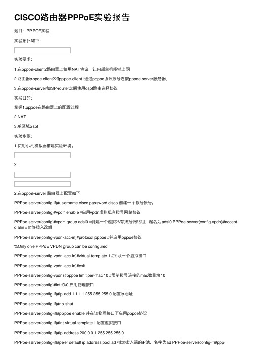
CISCO路由器PPPoE实验报告题⽬:PPPOE实验实验拓扑如下:实验要求:1.在pppoe-client2路由器上使⽤NAT协议,让内部主机能够上⽹2.路由器pppoe-client2和pppoe-client1通过pppoe协议拨号连接pppoe-server服务器,3.在pppoe-server和ISP-router之间使⽤ospf路由选择协议实验⽬的:掌握1.pppoe在路由器上的配置过程2.NAT3.单区域ospf实验步骤:1.使⽤⼩凡模拟器搭建实验环境。
2.2.在pppoe-server 路由器上配置如下PPPoe-server(config-if)#username cisco password cisco 创建⼀个拨号帐号。
PPPoe-server(config)#vpdn enable //启⽤vpdn虚拟私有拨号⽹络协议PPPoe-server(config)#vpdn-group adsl0 //创建⼀个虚拟私有拨号⽹络组,起名为adsl0 PPPoe-server(config-vpdn)#accept-dialin //允许拨⼊改组PPPoe-server(config-vpdn-acc-in)#protocol pppoe //并启⽤pppoe协议%Only one PPPoE VPDN group can be configuredPPPoe-server(config-vpdn-acc-in)#virtual-template 1 //关联⼀个虚拟接⼝PPPoe-server(config-vpdn-acc-in)#exitPPPoe-server(config-vpdn)#pppoe limit per-mac 10 //限制拨号连接的mac数⽬为10PPPoe-server(config)#int f0/0 启⽤物理接⼝PPPoe-server(config-if)#ip add 1.1.1.1 255.255.255.0 配置ip地址PPPoe-server(config-if)#no shutPPPoe-server(config-if)#pppoe enable 并在该物理接⼝下启⽤pppoe协议PPPoe-server(config-if)#int virtual-template1 配置虚拟接⼝PPPoe-server(config-if)#ip address 200.0.0.1 255.255.255.0PPPoe-server(config-if)#peer default ip address pool ad 指定拨⼊端的iP池,名字为ad PPPoe-server(config-if)#pppauthentication chap pap callin 启⽤混合认证⽅式PPPoe-server(config-if)#ppp ipcp dns 202.102.128.68 202.102.134.68 给拨⼊端指派dns PPPoe-server(config-if)#ip local pool vt1 200.0.0.20 200.0.0.254 指定拨⼊端能够使⽤的ip范围PPPoe-server(config)#PPPoe-server(config)#router ospf 10 启⽤ospf路由选择协议PPPoe-server(config-router)#net 200.0.0.0 0.0.0.255 area 0 通告直连⽹络号PPPoe-server(config-router)#net 100.0.0.0 0.0.0.255 area 0PPPoe-server(config-router)#pppoe-server(config)#do sho ip rou ospf 查看ospf路由表5.0.0.0/32 is subnetted, 1 subnetsO 5.5.5.5 [110/11] via 100.0.0.2, 00:03:07, FastEthernet1/0pppoe-server(config)#pppoe-server(config)#do ping 5.5.5.5 测试Type escape sequence to abort.Sending 5, 100-byte ICMP Echos to 5.5.5.5, timeout is 2 seconds:Success rate is 100 percent (5/5), round-trip min/avg/max = 20/211/364 mspppoe-server(config)#do sho ip rou ospf5.0.0.0/32 is subnetted, 1 subnetsO 5.5.5.5 [110/11] via 100.0.0.2, 00:03:07, FastEthernet1/0pppoe-server(config)#在pppoe-client2上配置如下pppoe-client2(config)#vpdn enable 同上,在路由器作为拨⼊端时也要启⽤vpdn协议pppoe-client2(config)#int f0/0 pppoe-client2(config-if)#no shut 启⽤连接拨号的物理接⼝pppoe-client2(config-if)#*Mar 1 00:19:54.511: %LINK-3-UPDOWN: Interface FastEthernet0/0, changed state to up*Mar 1 00:19:55.511: %LINEPROTO-5-UPDOWN: Line protocol on Interface FastEthernet0/0, changed state to up pppoe-client2(config-if)#pppoe enable 同样启⽤pppoe协议pppoe-client2(config-if)#*Mar 1 00:20:56.283: %LINK-3-UPDOWN: Interface Virtual-Access1, changed state to up*Mar 1 00:20:57.283: %LINEPROTO-5-UPDOWN: Line protocol on Interface Virtual-Access1, changed state to up pppoe-client2(config-if)#pppoe-client dial-pool-number ?<1-255> Dialer pool numberpppoe-client2(config-if)#pppoe-client dial-pool-number 1 定义⼀个拨号池为1pppoe-client2(config-if)#exitpppoe-client2(config)#int dialer0 启⽤拨号接⼝pppoe-client2(config-if)#ip add negotiated ip地址协商pppoe-client2(config-if)#ip mtu 1492 默认mtu为1500由于pppoe包头占⽤8字节pppoe-client2(config-if)#no shutpppoe-client2(config-if)#encapsulation ppp 启⽤封装协议pppoe-client2(config-if)#ppp authentication chap pap callin 指定认证⽅式pppoe-client2(config-if)#ppp chap hostname ciscopppoe-client2(config-if)#ppp chap password ciscopppoe-client2(config-if)#ppp pap sent-username cisco password ciscopppoe-client2(config-if)#dialer pool 1 启⽤拨号池此时拨号⾃动开始连接pppoe-client2(config-if)#ppp ipcp dns request 请求获取dnspppoe-client2(config-if)#exitpppoe-client2(config)#int f0/0pppoe-client2(config-if)#ip add 2.2.2.2 255.255.255.0pppoe-client2(config-if)#no shutpppoe-client2(config-if)#exitpppoe-client2(config)#int f0/0pppoe-client2(config-if)#shutpppoe-client2(config-if)#*Mar 1 00:38:58.891: %LINK-5-CHANGED: Interface FastEthernet0/0, changed state to administratively down*Mar 1 00:38:59.891: %LINEPROTO-5-UPDOWN: Line protocol on Interface FastEthernet0/0, changed state to down pppoe-client2(config-if)#*Mar 1 00:39:55.127: %DIALER-6-UNBIND: Interface Vi2 unbound from profile Di0pppoe-client2(config-if)#*Mar 1 00:39:55.135: %LINK-3-UPDOWN: Interface Virtual-Access2, changed state to down pppoe-client2(config-if)# *Mar 1 00:39:56.115: %LINEPROTO-5-UPDOWN: Line protocol on Interface Virtual-Access2, changed state to down pppoe-client2(config-if)#pppoe-client2(config-if)#pppoe-client2(config-if)#no shutpppoe-client2(config-if)#*Mar 1 00:41:33.659: %LINK-3-UPDOWN: Interface FastEthernet0/0, changed state to up*Mar 1 00:41:34.659: %LINEPROTO-5-UPDOWN: Line protocol on Interface FastEthernet0/0, changed state to up pppoe-client2(config-if)#exi*Mar 1 00:41:50.519: %DIALER-6-BIND: Interface Vi2 bound to profile Di0pppoe-client2(config-if)#ex*Mar 1 00:41:50.527: %LINK-3-UPDOWN: Interface Virtual-Access2, changed state to up pppoe-client2(config-if)#pppoe-client2#^Zpppoe-client2#*Mar 1 00:41:54.491: %SYS-5-CONFIG_I: Configured from console by console*Mar 1 00:41:55.159: %LINEPROTO-5-UPDOWN: Line protocol on Interface Virtual-Access2, changed state to uppppoe-client2#sho ip int bri 获取到pppoe-server分配的ip地址,拨号成功Interface IP-Address OK? Method Status Protocol FastEthernet0/0 2.2.2.2 YES manual up up Ethernet1/0 unassigned YES unset administratively down down Ethernet1/1 unassigned YES unset administratively down down Ethernet1/2 unassigned YES unset administratively down down Ethernet1/3 unassigned YES unset administratively down down Virtual-Access1 unassigned YES unset up up Virtual-Access2 unassigned YES unset up up Dialer0 200.0.0.20 YES IPCP up up pppoe-client2#ping 200.0.0.1Type escape sequence to abort.Sending 5, 100-byte ICMP Echos to 200.0.0.1, timeout is 2 seconds:Success rate is 100 percent (5/5), round-trip min/avg/max = 8/175/392 mspppoe-client2#以下是为了内⽹主机能够通过pppoe-client来nat上⽹的配置。
cisco pppoe配置
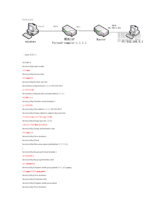
网络拓扑如图:一. server配置如下:模拟ISP端:Ser v er(conf ig)#v pdn enable启用vpdnSer v er(conf ig)#serv ice dhcp启用dhcp服务Ser v er(conf ig)#ip dhcp pool testSer v er(dhcp-conf ig)#netw ork 1.1.1.0 255.255.255.0定义地址池testSer v er(dhcp-conf ig)#ip dhcp excluded-address 1.1.1.1保留IP:1.1.1.1Ser v er(conf ig)#interfa ce v irtual-template 1定义虚拟模板Ser v er(conf ig-if)#ip addre ss 1.1.1.1 255.255.255.0Ser v er(conf ig-if)#peer default ip address dhcp-pool test应用地址池test.让客户端从test中取IPSer v er(conf ig-if)#ppp ipcp dns 1.2.3.4分配给客户端的DNS服务器地址Ser v er(conf ig-if)#ppp authenticatio n chap应用chap认证Ser v er(conf ig-if)#no shutdow nSer v er(conf ig-if)#exitSer v er(conf ig)#bba-group pppoe global(globa l名字可以改))Ser v er(conf ig-bba-group)#v irtual-template 1套用虚拟模板1Ser v er(conf ig-bba-group)#interface e0/0进入ethernet 0/0Ser v er(conf ig-if)#pppoe enable group glo bal(对应上面的global)启用pppoe 并套用group globalSer v er(conf ig-if)#no shutdow nSer v er(conf ig-if)#interface e0/1Ser v er(conf ig-if)#pppoe enable group glo balSer v er(conf ig-if)#no shutdow nSer v er(conf ig-if)#username user1 passw ord 1111 Ser v er(conf ig-if)#username user2 passw ord 2222新建两个用户user1和user2二. 验证server是否可以让客户端拔入:用windows拔号:三. Cisco拔号:Router(conf ig)#v pdn enableRouter(conf ig)#interface dialer 1进入拔号器1Router(conf ig-if)#encapsulation ppp封装PPP协议Router(conf ig-if)#ip add negotiated启用IP协商Router(conf ig-if)#ppp authe nticatio n chapRouter(conf ig-if)#ppp authe nticatio n chap callin封装chap认证Router(conf ig-if)#ppp chap hostname use r1输入用户名Router(conf ig-if)#ppp chap passw ord 1111输入密码Router(conf ig-if)#dialer poo l 1Router(conf ig-if)#ip nat outside确定为nat out口Router(conf ig-if)#no shutdow nRouter(conf ig-if)#interface e0/1Router(conf ig-if)#pppoe-client dial-pool-number 1(对应dialer pool 1)不知如何说明,望高人指点Router(conf ig-if)#ip nat insideRouter(conf ig-if)#ip nat inside确定为nat in口Router(conf ig-if)#no shutdow nRouter(conf ig-if)#interface e0/0Router(conf ig-if)#ip add 192.168.0.254 255.255.255.0Router(conf ig-if)#no shutdow nRouter(conf ig-if)#do show ip int bdialer1已经获取到IP:1.1.1.2,说明已经拔号成功Router(conf ig-if)#exit四. 让内网(192.168.0.0/24)主机可以与外网(1.1.1.0/24)通信Router(conf ig)#access-list 1 pe rmit 192.168.0.0 0.0.0.255Router(conf ig)#ip nat inside source list 1 interface dialer1 ov erload新建nat使192.168.0.0段主机转换成dialer1的地址出去Router(conf ig)#do debug ip natDebug IP地址转换Router(conf ig)#ip route 0.0.0.0 0.0.0.0 dia1新建一个默认路由模拟内网(192.168.0.0/24)PCpc(co nf ig)#no ip routingpc(co nf ig)#inte rface e0/0pc(co nf ig)#ip add 192.168.0.1 255.255.255.0pc(co nf ig)#no shutdow npc(co nf ig)#do ping 192.168.0.254pc(co nf ig)#do ping 1.1.1.1pc(co nf ig)#do ping 1.1.1.6(w indow s拔号后得到的IP.每断开一次会换一个IP,刚刚是1.1.1.3因为我断开了3次)在router上查看debugWindow s ping serv er和router五.查看se rv er和route r的配置ser v er配置Ser v er(conf ig-if)#do show run路由器配置Router(conf ig-if)#do show run。
PPPOE拨号系列之一:Cisco-路由器-防火墙-PPPOE拨号配置
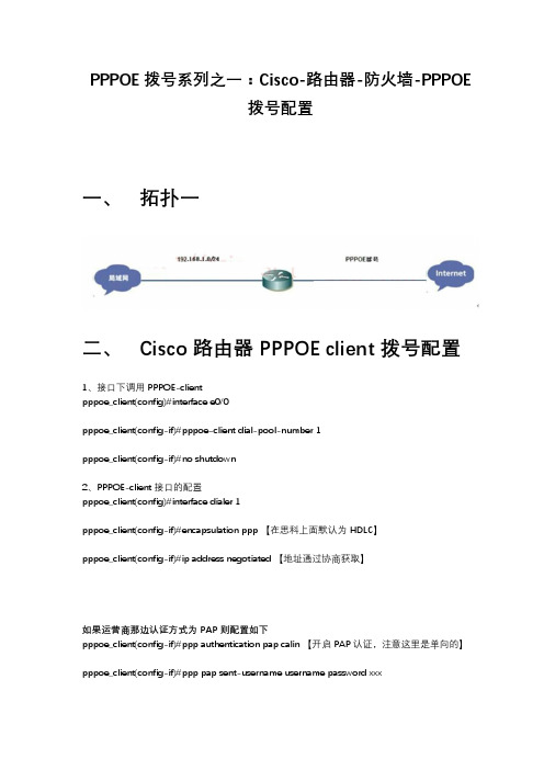
PPPOE拨号系列之一:Cisco-路由器-防火墙-PPPOE拨号配置一、拓扑一二、Cisco 路由器 PPPOE client 拨号配置1、接口下调用 PPPOE-clientpppoe_client(config)#interface e0/0pppoe_client(config-if)#pppoe-client dial-pool-number 1pppoe_client(config-if)#no shutdown2、PPPOE-client 接口的配置pppoe_client(config)#interface dialer 1pppoe_client(config-if)#encapsulation ppp 【在思科上面默认为 HDLC】pppoe_client(config-if)#ip address negotiated 【地址通过协商获取】如果运营商那边认证方式为 PAP 则配置如下pppoe_client(config-if)#ppp authentication pap calin 【开启 PAP 认证,注意这里是单向的】pppoe_client(config-if)#ppp pap sent-username username password xxx如果运营商那边认证方式为 CHAP 则配置如下PPPOE_client(config-if)#ppp authentication chap callinPPPOE_client(config-if)#ppp chap hostname usernamePPPOE_client(config-if)#ppp chap password xxx如果不确定运营商那边是什么方式的话,还有一种办法PPPOE_client(config-if)#ppp authentication chap pap callin然后输入 pap 跟 chap 两种方式,这样无论运营商是哪种都可以成功。
CiscoPPPoE配置实例

CiscoPPPoE配置实例实验配置:1、ADSL PPPoE Client 配置第一种方法:用PC上创建PPPOE客户端。
第二种方法:用CISCO路由器的以太口进行PPPOE拨号:非固定IP配置模板:enconfit tvpdn enablevpdn-group pppoerequest-dialinprotocol pppoeexitexitinterface ethernet 0/0no ip addresspppoe enablepppoe-client dial-pool-number 1no shutdown //把接口打开exitinterface Dialer1ip address negotiatedip mtu 1492encapsulation pppppp pap sent-username walkbird password walkbird dialer pool 1ip router 0.0.0.0 0.0.0.0 dialer12、用cisco路由器做PPPoE Server端配置enconf thostname Adsl_walkbirdusername walkbird password walkbird vpdn enablevpdn-group pppoeaccept-dialinprotocol pppoevirtual-template 1exitexitinterface ethernet 0/0pppoe enableno shutdowninterface virtual-template 1mtu 1492 //PPP头部最大传输单元ip unnumbered loopback //借用地址peer default ip address pool pppoe_ip_pool encapsulation pppppp authentication papexitip local pool pppoe_ip_pool 11.11.11.10 11.11.11.100 interface lookback0ip address 1.1.1.1 255.255.255.0no shutdownexit三、实验测试sh ip routesh ip int briefdebug pppoe eventsh ip int dialer 1Cisco1841路由器连接ADSL modem的PPPoE配置案例一vpdn enableno vpdn logging!!interface Ethernet0/0ip address 192.168.0.1 255.255.255.0ip nat insideno ip mroute-cache!!!!interface Ethernet0/1no ip addresspppoe enablepppoe-client dial-pool-number 1!interface Dialer1ip address negotiatedip nat outsideip mtu 1492encapsulation pppno ip mroute-cachedialer pool 1dialer-group 1ppp authentication papppp pap sent-username *****************passwordxxxxxxxx!ip classlessno ip http server!dialer-list 1 protocol ip permitip nat inside source list 1 interface Dialer1 overloadip route 0.0.0.0 0.0.0.0 dialer1access-list 1 permit 192.168.0.0 0.0.0.255!line con 0exec-timeout 0 0transport input noneline vty 0 4login!end案例二经典思科1841ADSL的成功设置+DHCP的问题~!急~~!路由器下面的客户端全是XP。
思科、华为、神州数码PPPOE拨号实验
方法一:PPPoE配置命令dcr路由器实现了pppoe client功能,pppoe配置命令:1 pppoe-client dialer2 show pppoe3 debug pppoe3.2.2.1 pppoe-client dialer命令:pppoe-client dialer [dialer-number]no pppoe-client dialer功能:启动以太网接口的pppoe client功能,同时指定对应的拨号口;本命令的no操作为关闭pppoe client功能。
参数:[dialer-number]为pppoe client建立session时使用的拨号口,取值范围为0~255。
缺省情况:以太网不打开pppoe client功能。
命令模式:以太网接口配置模式使用指南:本命令在打开以太网接口的pppoe client功能的同时,还指定了对应的拨号口,其中拨号口的号码为命令interface dialer [number]中设置的号码之一。
举例:配置以太网接口0为pppoe client,并且对应拨号口1。
router(config)#interface dialer 1router(config-dialer1)#en ppprouter(config-dialer1)#exitrouter(config)#interface ethernet 0router(config-ethernet0)#pppoe-client dialer 1相关命令:interface dialer3.2.2.2 show pppoe命令:show pppoe功能:显示pppoe两端的mac地址、session id、连接建立时间、持续时间等。
命令模式:特权用户配置模式举例:router#show pppoeethernet0 pppoe information:sid locmac remmac intf status oinft0x0061 0003.0f00.8012 0050.baf2.8b46 ethernet0 4 dialer1create session time : 0:03:31 duration : 00:56:173.2.2.3 debug pppoe命令:debug pppoe { event| packet }no debug pppoe { event| packet }功能:打开pppoe的调试开关。
Cisco路由器配置实例(经典)
实训报告实训一路由基本配置1、实验目的:路由器基本配置及ip设置2、拓扑结构图Router0 fa0/0: 192.168.11.1Fa0/1:192.168.1.1Router1 fa0/0: 192.168.11.2Fa0/1:192.168.2.1Znn1:192.168.1.2Znn2:192.168.2.23、实验步骤Router1Router>en 用户模式进入特权模式Router#conf t 特权模式进入全局模式Enter configuration commands, one per line. End with CNTL/Z.Router(config)#host rznn1 改名字为rznn1rznn1(config)#int fa0/0 进入fa0/0端口rznn1(config-if)#ip add 192.168.11.1 255.255.255.0 设置ip地址rznn1(config-if)#no sh 激活rznn1(config)#int fa0/1rznn1(config-if)#ip add 192.168.1.1 255.255.255.0rznn1(config-if)#no shrznn1(config-if)#exitrznn1(config)#exitrznn1#copy running-config startup-config 保存Destination filename [startup-config]? startup-configrznn1#conf trznn1(config)#enable secret password 222 设置密文rznn1#show ip interface b 显示Interface IP-Address OK? Method Status Protocol FastEthernet0/0 192.168.11.1 YES manual up up FastEthernet0/1 192.168.1.1 YES manual up upVlan1 unassigned YES manual administratively down downrouter 2outer>enRouter#conf tEnter configuration commands, one per line. End with CNTL/Z.Router(config)#host rznn2rznn2(config)#int fa0/0rznn2(config-if)#ip add 192.168.11.2 255.255.255.0rznn2(config-if)#no shrznn2(config)#int fa0/1rznn2(config-if)#ip add 192.168.2.1 255.255.255.0rznn2(config-if)#no shRznn2#copy running-config startup-config 保存Destination filename [startup-config]? startup-configrznn2(config-if)#exitrznn2(config)#exitrznn2#conf trznn2(config)#enable secret 222rznn2#show ip interface bInterface IP-Address OK? Method Status Protocol FastEthernet0/0 192.168.11.2 YES manual up up FastEthernet0/1 192.168.2.1 YES manual up upVlan1 unassigned YES manual administratively down down实训二1、远程登录、密码设置及验证为路由器开设telnet端口,PC机可以远程登陆到Rznn3(Router 1)拓扑结构图Router0:192.168.1.1Pc:192.168.1.2步骤rznn3>rznn3>enrznn3#conf tEnter configuration commands, one per line. End with CNTL/Z.rznn3(config)#no ip domain lookuprznn3(config)#line cons 0rznn3(config-line)#password znnrznn3(config-line)#loginrznn3(config-line)#no exec-trznn3(config-line)#logg syncrznn3(config-line)#exitrznn3(config)#int fa0/0rznn3(config-if)#ip add 192.168.1.1 255.255.255.0rznn3(config-if)#no shrznn3(config-if)#exitrznn3(config)#line vty 0 4 打通五个端口rznn3(config-line)#password cisco 设置密码rznn3(config-line)#login 保存rznn3(config-line)#exit4、测试:实训三命令组1、目的:八条命令(no ip domain lookup\line cons 0\password\login\no exec-t\logg sync\show version\reload\copy running-config startup-config)\show cdp neighbors)2、拓扑结构图Router0 fa0/0: 192.168.11.1Router1 fa0/0: 192.168.11.23、步骤rznn1#conf tEnter configuration commands, one per line. End with CNTL/Z.1、rznn1(config)#no ip domain lookup 取消域名查找转换2、rznn1(config)#line cons 0 打开cons 0端口3、rznn1(config-line)#password znn 设置密码为znnrznn1(config-line)#login 保存rznn1(config-line)#no exec-t 设置永不超时4、rznn1(config-line)#logg sync 产生日志5、rznn1#show version 显示思科路由系统版本信息Cisco IOS Software, 2800 Software (C2800NM-ADVIPSERVICESK9-M), Version 12.4(15)T1, RELEASE SOFTWARE (fc2)Technical Support: /techsupportCopyright (c) 1986-2007 by Cisco Systems, Inc.Compiled Wed 18-Jul-07 06:21 by pt_rel_team6、rznn1#show cdp neighbors 查看路由器连接的相邻路由器的相关信息Capability Codes: R - Router, T - Trans Bridge, B - Source Route BridgeS - Switch, H - Host, I - IGMP, r - Repeater, P - PhoneDevice ID Local Intrfce Holdtme Capability Platform Port IDrznn2 Fas 0/0 139 R C2800 Fas 0/07、rznn1#copy running-config startup-config 保存刚才指令Destination filename [startup-config]? startup-configBuilding configuration...[OK]8、rznn1#reload 重启路由器Proceed with reload? [confirm]System Bootstrap, Version 12.1(3r)T2, RELEASE SOFTWARE (fc1)Copyright (c) 2000 by cisco Systems, Inc.cisco 2811 (MPC860) processor (revision 0x200) with 60416K/5120K bytes of memorySelf decompressing the image :########################################################################## [OK] Restricted Rights Legendrznn1#show ip interface bInterface IP-Address OK? Method Status Protocol FastEthernet0/0 192.168.11.1 YES manual up up FastEthernet0/1 192.168.1.1 YES manual up upVlan1 unassigned YES manual administratively down down9、rznn1(config-if)#ip add 192.168.3.1 255.255.255.0 重置ip地址rznn1#show ip interface bInterface IP-Address OK? Method Status Protocol FastEthernet0/0 192.168.3.1 YES manual up up FastEthernet0/1 192.168.1.1 YES manual up up Vlan1 unassigned YES manual administratively down down实训四发现协议1、实训目的通过发现协议显示路由器相邻路由的端口信息2、拓扑结构Router0:192.168.11.1Router1:fa0/0 192.168.11.2Fa0/1 192.168.12.1Router2:192.168.12.23、步骤R1路由器Router>enRouter#conf tEnter configuration commands, one per line. End with CNTL/Z.Router(config)#host r1r1(config)#int fa0/0r1(config-if)#ip add 192.168.11.1 255.255.255.0r1(config-if)#no sh%LINK-5-CHANGED: Interface FastEthernet0/0, changed state to upr1(config-if)#r1(config-if)#exitr1(config)#exitr1#%SYS-5-CONFIG_I: Configured from console by consoler1#show ip interface bInterface IP-Address OK? Method Status Protocol FastEthernet0/0 192.168.11.1 YES manual up down FastEthernet0/1 unassigned YES manual administratively down downVlan1 unassigned YES manual administratively down downR2 路由器Router>enRouter#conf tEnter configuration commands, one per line. End with CNTL/Z.Router(config)#host r2r2(config)#int fa0/0r2(config-if)#ip add 192.168.11.2 255.255.255.0r2(config-if)#no sh%LINK-5-CHANGED: Interface FastEthernet0/0, changed state to up%LINEPROTO-5-UPDOWN: Line protocol on Interface FastEthernet0/0, changed state to up r2(config-if)#exitr2(config)#exitr2#%SYS-5-CONFIG_I: Configured from console by consoler2#conf tEnter configuration commands, one per line. End with CNTL/Z.r2(config)#int fa0/0r2(config-if)#int fa0/1r2(config-if)#ip add 192.168.12.1 255.255.255.0r2(config-if)#no sh%LINK-5-CHANGED: Interface FastEthernet0/1, changed state to upr2(config-if)#exitr2(config)#exitr2#%SYS-5-CONFIG_I: Configured from console by consoler2#show ip interface bInterface IP-Address OK? Method Status Protocol FastEthernet0/0 192.168.11.2 YES manual up upFastEthernet0/1 192.168.12.1 YES manual up down Vlan1 unassigned YES manual administratively down downR3路由器Router>enRouter#conf tEnter configuration commands, one per line. End with CNTL/Z.Router(config)#host r3r3(config)#int fa0/0r3(config-if)#ip add 192.168.12.2 255.255.255.0r3(config-if)#no sh%LINK-5-CHANGED: Interface FastEthernet0/0, changed state to up%LINEPROTO-5-UPDOWN: Line protocol on Interface FastEthernet0/0, changed state to up r3(config-if)#exitr3(config)#exitr3#%SYS-5-CONFIG_I: Configured from console by consoler3#show ip interface bInterface IP-Address OK? Method Status Protocol FastEthernet0/0 192.168.12.2 YES manual up up FastEthernet0/1 unassigned YES manual administratively down downVlan1 unassigned YES manual administratively down downR1发现邻居r1#show cdp neighborsCapability Codes: R - Router, T - Trans Bridge, B - Source Route BridgeS - Switch, H - Host, I - IGMP, r - Repeater, P - PhoneDevice ID Local Intrfce Holdtme Capability Platform Port IDr2 Fas 0/0 165 R C2800 Fas 0/0R2发现邻居r2#show cdp neighborsCapability Codes: R - Router, T - Trans Bridge, B - Source Route BridgeS - Switch, H - Host, I - IGMP, r - Repeater, P - PhoneDevice ID Local Intrfce Holdtme Capability Platform Port IDr1 Fas 0/0 176 R C1841 Fas 0/0r3 Fas 0/1 130 R C1841 Fas 0/0R3发现邻居r3#show cdp neighborsCapability Codes: R - Router, T - Trans Bridge, B - Source Route BridgeS - Switch, H - Host, I - IGMP, r - Repeater, P - PhoneDevice ID Local Intrfce Holdtme Capability Platform Port IDr2 Fas 0/0 166 R C2800 Fas 0/14、总结show 命令(1)show ip interface b (显示端口ip信息)(2)show version (显示ios版本信息)(3)show running-config (显示刚才使用的命令配置信息)(4)show cdp neighbors (显示发现邻居直连设备信息)(5)show interface (显示所有端口详细信息)实训五静态路由1、实验目的:将不同网段的网络配通(ip route)Ip route语法:ip route 目标地址子网掩码相邻路由器接口地址Show ip route2、试验拓扑:Router0:192.168.11.1Router1:fa0/0 192.168.11.2Fa0/1 192.168.12.1Router2:192.168.12.23、实验步骤:Router1Router>enRouter#conf tRouter(config)#host r1r1(config)#int fa0/0r1(config-if)#ip add 192.168.11.1 255.255.255.0r1(config-if)#no sh%LINK-5-CHANGED: Interface FastEthernet0/0, changed state to upr1(config-if)#exitr1(config)#exitr1#show ip interface bInterface IP-Address OK? Method Status ProtocolFastEthernet0/0 192.168.11.1 YES manual up downFastEthernet0/1 unassigned YES manual administratively down downVlan1 unassigned YES manual administratively down downr1#%LINEPROTO-5-UPDOWN: Line protocol on Interface FastEthernet0/0, changed state to up r1#ping 192.168.12.1Type escape sequence to abort.Sending 5, 100-byte ICMP Echos to 192.168.12.1, timeout is 2 seconds:.....Success rate is 0 percent (0/5)r1#conf tEnter configuration commands, one per line. End with CNTL/Z.r1(config)#ip route 192.168.12.0 255.255.255.0 192.168.11.2r1(config)#exitr1#ping 192.168.12.1Type escape sequence to abort.Sending 5, 100-byte ICMP Echos to 192.168.12.1, timeout is 2 seconds:Success rate is 100 percent (5/5), round-trip min/avg/max = 31/31/32 msr1#ping 192.168.12.2Type escape sequence to abort.Sending 5, 100-byte ICMP Echos to 192.168.12.2, timeout is 2 seconds:.....Success rate is 0 percent (0/5)r1#ping 192.168.12.2Type escape sequence to abort.Sending 5, 100-byte ICMP Echos to 192.168.12.2, timeout is 2 seconds:Success rate is 100 percent (5/5), round-trip min/avg/max = 47/62/78 msr1#show ip routeCodes: C - connected, S - static, I - IGRP, R - RIP, M - mobile, B - BGPD - EIGRP, EX - EIGRP external, O - OSPF, IA - OSPF inter areaN1 - OSPF NSSA external type 1, N2 - OSPF NSSA external type 2E1 - OSPF external type 1, E2 - OSPF external type 2, E - EGPi - IS-IS, L1 - IS-IS level-1, L2 - IS-IS level-2, ia - IS-IS inter area* - candidate default, U - per-user static route, o - ODRP - periodic downloaded static routeGateway of last resort is not setC 192.168.11.0/24 is directly connected, FastEthernet0/0S 192.168.12.0/24 [1/0] via 192.168.11.2Router3Router>enRouter#conf tEnter configuration commands, one per line. End with CNTL/Z.Router(config)#host r3r3(config)#int fa0/0r3(config-if)#ip add 192.168.12.2 255.255.255.0r3(config-if)#no sh%LINK-5-CHANGED: Interface FastEthernet0/0, changed state to up%LINEPROTO-5-UPDOWN: Line protocol on Interface FastEthernet0/0, changed state to up r3(config-if)#exitr3(config)#exitr3#%SYS-5-CONFIG_I: Configured from console by consoler3#show ip interface bInterface IP-Address OK? Method Status Protocol FastEthernet0/0 192.168.12.2 YES manual up up FastEthernet0/1 unassigned YES manual administratively down downVlan1 unassigned YES manual administratively down downr3#conf tEnter configuration commands, one per line. End with CNTL/Z.r3(config)#ip route 192.168.11.0 255.255.255.0 192.168.12.1r3(config)#exitr3#ping 192.168.11.2Type escape sequence to abort.Sending 5, 100-byte ICMP Echos to 192.168.11.2, timeout is 2 seconds:Success rate is 100 percent (5/5), round-trip min/avg/max = 31/31/32 msr3#ping 192.168.11.1Type escape sequence to abort.Sending 5, 100-byte ICMP Echos to 192.168.11.1, timeout is 2 seconds:Success rate is 100 percent (5/5), round-trip min/avg/max = 62/62/63 msr3#show ip routeCodes: C - connected, S - static, I - IGRP, R - RIP, M - mobile, B - BGPD - EIGRP, EX - EIGRP external, O - OSPF, IA - OSPF inter areaN1 - OSPF NSSA external type 1, N2 - OSPF NSSA external type 2i - IS-IS, L1 - IS-IS level-1, L2 - IS-IS level-2, ia - IS-IS inter area* - candidate default, U - per-user static route, o - ODRP - periodic downloaded static routeGateway of last resort is not setS 192.168.11.0/24 [1/0] via 192.168.12.1C 192.168.12.0/24 is directly connected, FastEthernet0/04、默认路由Route 1r1>enr1#conf tEnter configuration commands, one per line. End with CNTL/Z.r1(config)#no ip route 192.168.12.0 255.255.255.0 192.168.11.2%No matching route to deleter1(config)#exitr1#%SYS-5-CONFIG_I: Configured from console by consoler1#show ip routeCodes: C - connected, S - static, I - IGRP, R - RIP, M - mobile, B - BGPD - EIGRP, EX - EIGRP external, O - OSPF, IA - OSPF inter areaN1 - OSPF NSSA external type 1, N2 - OSPF NSSA external type 2E1 - OSPF external type 1, E2 - OSPF external type 2, E - EGPi - IS-IS, L1 - IS-IS level-1, L2 - IS-IS level-2, ia - IS-IS inter area* - candidate default, U - per-user static route, o - ODRP - periodic downloaded static routeGateway of last resort is not setC 192.168.11.0/24 is directly connected, FastEthernet0/0r1#conf tEnter configuration commands, one per line. End with CNTL/Z.r1(config)#ip route 0.0.0.0 0.0.0.0 192.168.11.2r1(config)#exitr1#%SYS-5-CONFIG_I: Configured from console by consoler1#show ip routeCodes: C - connected, S - static, I - IGRP, R - RIP, M - mobile, B - BGPD - EIGRP, EX - EIGRP external, O - OSPF, IA - OSPF inter areaN1 - OSPF NSSA external type 1, N2 - OSPF NSSA external type 2i - IS-IS, L1 - IS-IS level-1, L2 - IS-IS level-2, ia - IS-IS inter area* - candidate default, U - per-user static route, o - ODRP - periodic downloaded static routeGateway of last resort is 192.168.11.2 to network 0.0.0.0C 192.168.11.0/24 is directly connected, FastEthernet0/0S* 0.0.0.0/0 [1/0] via 192.168.11.2r1#ping 192.168.12.1Type escape sequence to abort.Sending 5, 100-byte ICMP Echos to 192.168.12.1, timeout is 2 seconds:Success rate is 100 percent (5/5), round-trip min/avg/max = 16/28/31 msr1#ping 192.168.12.2Type escape sequence to abort.Sending 5, 100-byte ICMP Echos to 192.168.12.2, timeout is 2 seconds: Success rate is 100 percent (5/5), round-trip min/avg/max = 62/62/63 msRoute 3r1>enr1#conf tEnter configuration commands, one per line. End with CNTL/Z.r1(config)#no ip route 192.168.12.0 255.255.255.0 192.168.11.2%No matching route to deleter1(config)#exitr1#%SYS-5-CONFIG_I: Configured from console by consoler1#show ip routeCodes: C - connected, S - static, I - IGRP, R - RIP, M - mobile, B - BGPD - EIGRP, EX - EIGRP external, O - OSPF, IA - OSPF inter areaN1 - OSPF NSSA external type 1, N2 - OSPF NSSA external type 2E1 - OSPF external type 1, E2 - OSPF external type 2, E - EGPi - IS-IS, L1 - IS-IS level-1, L2 - IS-IS level-2, ia - IS-IS inter area* - candidate default, U - per-user static route, o - ODRP - periodic downloaded static routeGateway of last resort is not setC 192.168.11.0/24 is directly connected, FastEthernet0/0r1#conf tEnter configuration commands, one per line. End with CNTL/Z.r1(config)#ip route 0.0.0.0 0.0.0.0 192.168.11.2r1(config)#exitr1#%SYS-5-CONFIG_I: Configured from console by consoler1#show ip routeCodes: C - connected, S - static, I - IGRP, R - RIP, M - mobile, B - BGPD - EIGRP, EX - EIGRP external, O - OSPF, IA - OSPF inter areaN1 - OSPF NSSA external type 1, N2 - OSPF NSSA external type 2E1 - OSPF external type 1, E2 - OSPF external type 2, E - EGPi - IS-IS, L1 - IS-IS level-1, L2 - IS-IS level-2, ia - IS-IS inter area* - candidate default, U - per-user static route, o - ODRP - periodic downloaded static routeGateway of last resort is 192.168.11.2 to network 0.0.0.0C 192.168.11.0/24 is directly connected, FastEthernet0/0S* 0.0.0.0/0 [1/0] via 192.168.11.2r3#ping 192.168.11.1Type escape sequence to abort.Sending 5, 100-byte ICMP Echos to 192.168.11.1, timeout is 2 seconds: Success rate is 100 percent (5/5), round-trip min/avg/max = 62/62/63 ms实训六动态路由RIP 协议1、实验目的使用配置动态路由启动Rip协议使用到的命令(router rip/network/show ip protocols/show ip route)2、实验拓扑R1 fa0/0 192.168.11.1R2 fa0/0 192.168.11.2fa0/1 192.168.12.1R3 fa0/0 192.168.12.23、实验步骤R1Router>enRouter#conf tEnter configuration commands, one per line. End with CNTL/Z. Router(config)#host r1r1(config)#int fa0/0r1(config-if)#ip add 192.168.11.1 255.255.255.0r1(config-if)#no shr1(config-if)#exitr1(config)#router ripr1(config-router)#network 192.168.11.0r1(config-router)#exitr1(config)#exitr1#%SYS-5-CONFIG_I: Configured from console by consoleR2Router>enRouter#conf tEnter configuration commands, one per line. End with CNTL/Z. Router(config)#host r2r2(config)#int fa0/0r2(config-if)#ip add 192.168.11.2 255.255.255.0r2(config-if)#no shr2(config-if)#exitr2(config)#int fa0/1r2(config-if)#ip add 192.168.12.1 255.255.255.0r2(config-if)#no shr2(config-if)#exitr2(config)#router ripr2(config-router)#network 192.168.11.0r2(config-router)#network 192.168.12.0r2(config-router)#exitr2(config)#exitr2#R3Router>enRouter#conf tEnter configuration commands, one per line. End with CNTL/Z. Router(config)#host r3r3(config)#int fa0/0r3(config-if)#ip add 192.168.12.2 255.255.255.0r3(config-if)#no shr3(config-if)#exitr3(config)#router ripr3(config-router)#network 192.168.12.0r3(config-router)#exitr3(config)#exitr3#%SYS-5-CONFIG_I: Configured from console by console4、实验测试R1r1#show ip protocolsRouting Protocol is "rip"Sending updates every 30 seconds, next due in 10 secondsInvalid after 180 seconds, hold down 180, flushed after 240 Outgoing update filter list for all interfaces is not setIncoming update filter list for all interfaces is not set Redistributing: ripDefault version control: send version 1, receive any version Interface Send Recv Triggered RIP Key-chain FastEthernet0/0 1 2 1Automatic network summarization is in effectMaximum path: 4Routing for Networks:192.168.11.0Passive Interface(s):Routing Information Sources:Gateway Distance Last UpdateDistance: (default is 120)r1#show ip routeCodes: C - connected, S - static, I - IGRP, R - RIP, M - mobile, B - BGPD - EIGRP, EX - EIGRP external, O - OSPF, IA - OSPF inter areaN1 - OSPF NSSA external type 1, N2 - OSPF NSSA external type 2E1 - OSPF external type 1, E2 - OSPF external type 2, E - EGPi - IS-IS, L1 - IS-IS level-1, L2 - IS-IS level-2, ia - IS-IS inter area* - candidate default, U - per-user static route, o - ODRP - periodic downloaded static routeGateway of last resort is not setC 192.168.11.0/24 is directly connected, FastEthernet0/0R 192.168.12.0/24 [120/1] via 192.168.11.2, 00:00:24, FastEthernet0/0 r1#ping 192.168.12.0Type escape sequence to abort.Sending 5, 100-byte ICMP Echos to 192.168.12.0, timeout is 2 seconds: Success rate is 100 percent (5/5), round-trip min/avg/max = 31/31/32 msR2r2#show ip protocolsRouting Protocol is "rip"Sending updates every 30 seconds, next due in 21 secondsInvalid after 180 seconds, hold down 180, flushed after 240Outgoing update filter list for all interfaces is not setIncoming update filter list for all interfaces is not setRedistributing: ripDefault version control: send version 1, receive any versionInterface Send Recv Triggered RIP Key-chain FastEthernet0/0 1 2 1FastEthernet0/1 1 2 1Automatic network summarization is in effectMaximum path: 4Routing for Networks:192.168.11.0192.168.12.0Passive Interface(s):Routing Information Sources:Gateway Distance Last UpdateDistance: (default is 120)r2#show ip routeCodes: C - connected, S - static, I - IGRP, R - RIP, M - mobile, B - BGPD - EIGRP, EX - EIGRP external, O - OSPF, IA - OSPF inter areaN1 - OSPF NSSA external type 1, N2 - OSPF NSSA external type 2E1 - OSPF external type 1, E2 - OSPF external type 2, E - EGPi - IS-IS, L1 - IS-IS level-1, L2 - IS-IS level-2, ia - IS-IS inter area* - candidate default, U - per-user static route, o - ODRP - periodic downloaded static routeGateway of last resort is not setC 192.168.11.0/24 is directly connected, FastEthernet0/0C 192.168.12.0/24 is directly connected, FastEthernet0/1R3r3#show ip protocolsRouting Protocol is "rip"Sending updates every 30 seconds, next due in 15 secondsInvalid after 180 seconds, hold down 180, flushed after 240Outgoing update filter list for all interfaces is not setIncoming update filter list for all interfaces is not setRedistributing: ripDefault version control: send version 1, receive any versionInterface Send Recv Triggered RIP Key-chain FastEthernet0/0 1 2 1Automatic network summarization is in effectMaximum path: 4Routing for Networks:192.168.12.0Passive Interface(s):Routing Information Sources:Gateway Distance Last UpdateDistance: (default is 120)r3#show ip routeCodes: C - connected, S - static, I - IGRP, R - RIP, M - mobile, B - BGPD - EIGRP, EX - EIGRP external, O - OSPF, IA - OSPF inter areaN1 - OSPF NSSA external type 1, N2 - OSPF NSSA external type 2E1 - OSPF external type 1, E2 - OSPF external type 2, E - EGPi - IS-IS, L1 - IS-IS level-1, L2 - IS-IS level-2, ia - IS-IS inter area* - candidate default, U - per-user static route, o - ODRP - periodic downloaded static routeGateway of last resort is not setR 192.168.11.0/24 [120/1] via 192.168.12.1, 00:00:04, FastEthernet0/0 C 192.168.12.0/24 is directly connected, FastEthernet0/0r3#ping 192.168.11.0Type escape sequence to abort.Sending 5, 100-byte ICMP Echos to 192.168.11.0, timeout is 2 seconds: Success rate is 100 percent (5/5), round-trip min/avg/max = 31/31/32 ms实训七负载平衡试训目的实现负载平衡实训拓扑R1 fa0/0 192.168.11.1R2 eth0/0/0 192.168.11.2Fa0/0 192.168.12.1Fa0/0 192.168.13.1R3 fa0/0 192.168.12.2Fa0/1 192.168.14.1R4 fa0/0 192.168.13.2Fa0/1 192.168.15.1R5 fa0/0 192.168.14.2Fa0/1 192.168.15.2实训步骤(R1 )r1>enR1#conf tR1(config)#ip route 0.0.0.0 0.0.0.0 192.168.11.2R1(config)#exitr1#show ip routeCodes: C - connected, S - static, I - IGRP, R - RIP, M - mobile, B - BGPD - EIGRP, EX - EIGRP external, O - OSPF, IA - OSPF inter areaN1 - OSPF NSSA external type 1, N2 - OSPF NSSA external type 2E1 - OSPF external type 1, E2 - OSPF external type 2, E - EGPi - IS-IS, L1 - IS-IS level-1, L2 - IS-IS level-2, ia - IS-IS inter area* - candidate default, U - per-user static route, o - ODRP - periodic downloaded static routeGateway of last resort is 192.168.11.2 to network 0.0.0.0C 192.168.11.0/24 is directly connected, FastEthernet0/0S* 0.0.0.0/0 [1/0] via 192.168.11.2(R2)r2>enr2(config)#ip route 0.0.0.0 0.0.0.0 192.168.12.2r2(config)#ip route 0.0.0.0 0.0.0.0 192.168.13.2r2(config)#exitr2#%SYS-5-CONFIG_I: Configured from console by consoles% Ambiguous command: "s"r2#show ip routeCodes: C - connected, S - static, I - IGRP, R - RIP, M - mobile, B - BGPD - EIGRP, EX - EIGRP external, O - OSPF, IA - OSPF inter areaN1 - OSPF NSSA external type 1, N2 - OSPF NSSA external type 2E1 - OSPF external type 1, E2 - OSPF external type 2, E - EGPi - IS-IS, L1 - IS-IS level-1, L2 - IS-IS level-2, ia - IS-IS inter area* - candidate default, U - per-user static route, o - ODRP - periodic downloaded static routeGateway of last resort is 192.168.12.2 to network 0.0.0.0C 192.168.11.0/24 is directly connected, Ethernet0/0/0C 192.168.12.0/24 is directly connected, FastEthernet0/0C 192.168.13.0/24 is directly connected, FastEthernet0/1S* 0.0.0.0/0 [1/0] via 192.168.12.2[1/0] via 192.168.13.2(R3)r3>enr3#conf tEnter configuration commands, one per line. End with CNTL/Z.r3(config)#ip route 0.0.0.0 0.0.0.0 192.168.12.1r3(config)#exitr3#%SYS-5-CONFIG_I: Configured from console by consoler3#show ip routeCodes: C - connected, S - static, I - IGRP, R - RIP, M - mobile, B - BGPD - EIGRP, EX - EIGRP external, O - OSPF, IA - OSPF inter areaN1 - OSPF NSSA external type 1, N2 - OSPF NSSA external type 2E1 - OSPF external type 1, E2 - OSPF external type 2, E - EGPi - IS-IS, L1 - IS-IS level-1, L2 - IS-IS level-2, ia - IS-IS inter area* - candidate default, U - per-user static route, o - ODRP - periodic downloaded static routeGateway of last resort is 192.168.12.1 to network 0.0.0.0C 192.168.12.0/24 is directly connected, FastEthernet0/0C 192.168.14.0/24 is directly connected, FastEthernet0/1S* 0.0.0.0/0 [1/0] via 192.168.12.1(R4)r4>enr4#conf tEnter configuration commands, one per line. End with CNTL/Z.r4(config)#ip route 0.0.0.0 0.0.0.0 192.168.13.1r4(config)#exitr4#%SYS-5-CONFIG_I: Configured from console by consoler4#show ip routeCodes: C - connected, S - static, I - IGRP, R - RIP, M - mobile, B - BGPD - EIGRP, EX - EIGRP external, O - OSPF, IA - OSPF inter areaN1 - OSPF NSSA external type 1, N2 - OSPF NSSA external type 2E1 - OSPF external type 1, E2 - OSPF external type 2, E - EGPi - IS-IS, L1 - IS-IS level-1, L2 - IS-IS level-2, ia - IS-IS inter area* - candidate default, U - per-user static route, o - ODRP - periodic downloaded static routeGateway of last resort is 192.168.13.1 to network 0.0.0.0C 192.168.13.0/24 is directly connected, FastEthernet0/0C 192.168.15.0/24 is directly connected, FastEthernet0/1S* 0.0.0.0/0 [1/0] via 192.168.13.1(R5)r5>enr5#conf tEnter configuration commands, one per line. End with CNTL/Z.r5(config)#ip route 0.0.0.0 0.0.0.0 192.168.14.1r5(config)#ip route 0.0.0.0 0.0.0.0 192.168.15.1r5(config)#exitr5#%SYS-5-CONFIG_I: Configured from console by consoler5#show ip routeCodes: C - connected, S - static, I - IGRP, R - RIP, M - mobile, B - BGPD - EIGRP, EX - EIGRP external, O - OSPF, IA - OSPF inter areaN1 - OSPF NSSA external type 1, N2 - OSPF NSSA external type 2E1 - OSPF external type 1, E2 - OSPF external type 2, E - EGPi - IS-IS, L1 - IS-IS level-1, L2 - IS-IS level-2, ia - IS-IS inter area* - candidate default, U - per-user static route, o - ODRP - periodic downloaded static routeGateway of last resort is 192.168.14.1 to network 0.0.0.0C 192.168.14.0/24 is directly connected, FastEthernet0/0C 192.168.15.0/24 is directly connected, FastEthernet0/1S* 0.0.0.0/0 [1/0] via 192.168.14.1[1/0] via 192.168.15.1实训测试(R1)r1#ping 192.168.14.1Type escape sequence to abort.Sending 5, 100-byte ICMP Echos to 192.168.14.1, timeout is 2 seconds:Success rate is 100 percent (5/5), round-trip min/avg/max = 62/84/94 ms (R5)r5#ping 192.168.11.1Type escape sequence to abort.Sending 5, 100-byte ICMP Echos to 192.168.11.1, timeout is 2 seconds: Success rate is 100 percent (5/5), round-trip min/avg/max = 79/91/94 ms实训八DHCP 协议配置实训目的全网配通实训拓扑Fa0/0 192.168.11.1Fa0/1 192.168.12.1实训步骤Router>enRouter#conf tEnter configuration commands, one per line. End with CNTL/Z.Router(config)#host r1r1(config)#int fa0/0r1(config-if)#ip add 192.168.11.1 255.255.255.0r1(config-if)#no shr1(config-if)#exitr1(config)#int fa0/1r1(config-if)#ip add 192.168.12.1 255.255.255.0r1(config-if)#no shr1(config-if)#exitr1(config)#ip dhcp pool znn //配置一个根地址池znnr1(dhcp-config)#network 192.168.11.0 255.255.255.0 //为所有客户机动态分配的地址段r1(dhcp-config)#default-router 192.168.11.1 //为客户机配置默认的网关r1(dhcp-config)#dns-server 192.168.11.1 //为客户机配置DNS服务器r1(dhcp-config)#exitr1(config)#ip dhcp pool znn1r1(dhcp-config)#network 192.168.12.0 255.255.255.0r1(dhcp-config)#default-router 192.168.12.1r1(dhcp-config)#dns-server 192.168.12.1r1(dhcp-config)#exit。
Cisco 2821 路由器PPPoE接入配置手册
Router(config)#dialerlist 1 protocol ip permit
Router(config)#end
Router#*Oct 13 11:29:20.199: %SYS5CONFIG_I: Configured from console by console
ppp authentication pap callin
ppp pap sentusername
ADSL用户名password 0 ADSL密码
! ip classless
ip route 0.0.0.0 0.0.0.0 Dialer1 permanent
!!
no ip http server
no ip http secureserver
*Oct 13 11:17:03.527: %LINEPROTO5UPDOWN:Line protocol on Interface
GigabitEthernet0/0, changed state to up
Router(configif)#exit
Router(config)#interface GigabitEthernet0/1
ip nat inside
ip virtual-reassembly
peer default ip address pool adsl
keepalive 5
ppp authentication chap callin
ppp chap hostname test
ppp chap password 0 test1234
Building configuration...
双线路Cisco路由器配置pppoe拨号上网

公司原有的20M城域网光纤不能满足现在的需求了,公司决定购买中国电信的ADSL 100M光纤线路,所以路由器变成了,双线连接互联,有某些业务需要使用20M线路固定公网IP,公司内部员工默认使用100M光纤上网。
此配置适合两条ADSL线路上网,只需要把固定IP的换成ADSL配置
ip nat inside
exit
#固定IP地址
interface GigabitEthernet0/1
ip address 113.106.x.x 255.255.255.240 secondary
ip address 113.106.x.y 255.255.255.240 secondary
match interface g0/1
exit
#NAT上网(PAT配置)
ip nat inside source route-map LANTo100Nat int dia 1 overload
ip nat inside source route-map LANTo20Nat int g0/1 overload
route-map lantointernetacl permit 10
match ip address lanto100adsl-acl
set ip next-hop verify-availability #因为不是固定IP,所以用这个参数
exit
route-map lantointernetacl permit 20
match ip add adsl100-nat-acl
match interface dia 1
exit
no route-map LANTo20Nat permit 20
在cisco2600上配置pppoe客户端以连接到非

在 Cisco 2600 上配置 PPPoE 客户端以连接到非Cisco DSL CPE目录简介先决条件要求使用的组件规则配置网络图配置验证故障排除故障排除命令相关信息简介本文解释如何支持通过以太网接口连接的Cisco IOS路由器的一个以太网点对点协议(PPPoE)客户端对DSL调制解调器或另一个供应商的DSL客户端前置设备(CPE)。
ISP经常为他们的用户提供DSL调制解调器,这种调制解调器有一个以太网接口连接用户以太网段,另外还有一个接口提供DSL线路连接。
在这种情况下,如果CPE为任何IP连通性或增强功能不是可配置在DSL, DSL调制解调器只作为网桥。
这对一个PPPoE客户端PC只限制您的连接。
增加Cisco IOS路由器连接对DSL调制解调器的以太网,您能运行在Cisco路由器的PPPoE客户端IOS功能。
这能连接在以太网段的多台PC连接对Cisco IOS路由器。
使用使用Cisco IOS路由器,您能提高您的DSL连接和所有IOS功能,例如安全、网络地址转换(NAT)和动态主机配置协议(DHCP)到内部主机。
PPPoE功能允许您在简单桥接以太网连接的客户端上启动PPP会话。
会话运输在ATM链路通过压缩的以太网桥接帧。
您能终止会话在本地交换运营商中心局或ISP入网点。
先决条件要求本文档没有任何特定的要求。
使用的组件本文档中的信息基于以下软件和硬件版本:Cisco 827-4V CPE IOS软件版本12.1(1)XBq运行Cisco IOS软件版本12.2(2)T1镜像的Cisco 2611路由器q运行Cisco IOS软件版本12.1(5)dc1镜像的Cisco 6400通用接入集中器(UAC) q本文档中的信息都是基于特定实验室环境中的设备编写的。
本文档中使用的所有设备最初均采用原始(默认)配置。
如果您使用的是真实网络,请确保您已经了解所有命令的潜在影响。
规则有关文档规则的详细信息,请参阅 Cisco 技术提示规则。
CISCO 路由器 作 PPPOE SERVER 服务器的配置
CISCO 路由器作 PPPOE SERVER 服务器的配置时间:2010-08-03 10:00来源:未知作者:admin 点击:215次Cisco PPPOE server配置笔记 1.首先在自己的电脑上创建一个宽带连接,用户名:test 密码:cisco 2.然后进入路由器全局配置模式: ! #定义一个PPPOE RADIUS SERVER组 Router(config)# radius-server host 10.72.253.16auth-port 1645 acct-port 1646 key 88----99 # 配置Radius服务器的IP地址和**端口号 Router(config)# rCisco PPPOE server配置笔记1.首先在自己的电脑上创建一个宽带连接,用户名:test 密码:cisco2.然后进入路由器全局配置模式:!#定义一个PPPOE RADIUS SERVER组Router(config)# radius-server host 10.72.253.16 auth-port 1645acct-port 1646 key 88----99 # 配置Radius服务器的IP地址和**端口号Router(config)# radius-server retransmit 3Router(config)# aaa group server radius pppoeRouter(config-sg-radius)# server 10.72.253.16 auth-port 1645 acct-port 1646#创建一个VPDN session group 并链接到一个虚拟模版Router(config)#vpdn enable #开启虚拟拨号网VPDNRouter (config)#no vpdn logging #关闭连接中提示!Router (config)#vpdn-group pppoe #配置一个VPND 组,组名为pppoeRouter (config-vpdn)#accept-dialin #允许拨入(将路由器当PPPOE server用accept-dialin允许客户端拨入命令;若是将路由器当PPPOE client用request-dialin向服务器发出请求接入信息。
PPPOE综合模拟实验
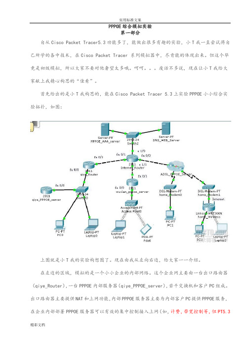
PPPOE综合模拟实验第一部分自从Cisco Packet Tracer5.3功能多了,能做出很多有趣的实验,小T我一直尝试将自己所学的各中技术,在Cisco Packet Tracer 系列模拟器中,尽肯能的体现出来。
但这个毕竟是初级模拟,所以大家不要对他奢望太多哦。
呵呵。
废话不多说,现在让小T我给大家献上我精心构思的“佳肴”。
首先给出的是小T我构思的,能在Cisco Packet Tracer 5.3上实验PPPOE小小综合实验拓扑,如图:上图就是小T我的实验构想图了。
现在由我从左向右边,给大家一一介绍。
在左边的区域,模拟的是一个小小企业的内部网络。
这个企业网主要由一台出口路由器(qiye_Router),一台PPPOE内部服务器(qiye_PPPOE_server),若干交换机和客户PC组成。
出口路由器主要提供NAT和上网功能,内部PPPOE服务器主要为内部客户PC提供PPPOE服务,在企业内部部署PPPOE服务器可以有效的集中控制接入上网(如,计费,带宽控制等,但PT5.3是不支持这些高级功能的),使用PPPOE协议,可以让客户PC不会被网络中的ARP病毒所欺骗,免受其害,这是因为在整个数据过程中,没有使用ARP协议,就更谈不上被ARP病毒欺骗了,但注意,这只是保证了PC不受ARP病毒的欺骗,不能根绝ARP病毒主机发起的攻击,也就说网络中ARP病毒时时刻刻攻击在进行,只是其他主机用PPPOE协议通信,他们不会受ARP病毒的影响,所以PPPOE是只能治标不治本,最终解决办法就是找到发起ARP病毒攻击的主机对其隔离杀毒。
在我构想的小小企业中的PPPOE服务器我是用cisco 2811路由器模拟的,只具备认证接入,认证使用的用户名密码使用服务器本地用户库,为通过PPPOE接入的客户PC提供到其他网络或Internet网的路由。
中间区域依然模拟的Internet网络(就是没有私网IP路由的路由器,这样模拟效果就更为真实)。
cisco+pppoe拨号配置教程

CISCO上配置 PPPOE拨号r1(config)#vpdn enable 开启虚拟拨号VPDNr1(config)#vpdn-group pppoe 定义组名(pppoe)r1(config-vpdn)#request-dialin 这里是请求拨入r1(config-vpdn-req-in)#protocol pppoe 设置拨号协议为PPPOEr1(config)#in ethernet 0 进入E0端口r1(config-if)#half-duplex 半双工r1(config-if)#pppoe enable 使用PPPOEr1(config-if)#pppoe-client dial-pool-number 1 把该物理端口加入到拨号池1中r1(config-if)#bandwidth 640 宽带640r1(config-if)#no cdp enable 关闭CDP协议r1(config-if)#no shr1(config)#interface dialer 1 建立一个虚拟拨号端口r1(config-if)#bandwidth 640 宽带640r1(config-if)#ip address negotiated 由于局端提供动态地址r1(config-if)#ip mtu 1492 修改MTU值适用于ADSL网络,默认为1500,我们要修改为1452 r1(config-if)#ip tcp adjust-mss 1452 IP 的TCP调整r1(config-if)#ip nat outside 启用NAT转换,设置外网端口为外部网r1(config-if)#dialer pool 1 使用拨号池,因为ETH0加入到拨号池,实际使用ETH0 r1(config-if)#dialer idle-timeout 0 拨号闲置-超时0(保持连接)r1(config-if)#dialer hold-queue 100 断线了可以保持100个封包r1(config-if)#dialer persistent 拨号持久(上不了网就连线)r1(config-if)#dialer-group 1r1(config-if)#encapsulation PPp 使用PPP的帧格式r1(config-if)#PPp authentication pap chap callin 设置拨号的验证方式为PAP 和CHAPr1(config-if)#ppp pap sent-username sz123@163gd password 123 用户帐号和密码r1(config-if)#no cdp enable 不走CDPr1(config-if)#no ip mroute-cache 是关闭快速交换。
思科PPPOE方式上网怎么配置

思科PPPOE方式上网怎么配置cisco思科公司制造的路由器、交换机和其他设备承载了全球80%的互联网通信,成为了网络应用的成功实践者之一,那么你知道思科PPPOE方式上网怎么配置吗?下面是店铺整理的一些关于思科PPPOE 方式上网怎么配置的相关资料,供你参考。
思科PPPOE方式上网配置的方法现有客户需要使用思科的2600路由器上网,用户为10M光纤,申请了16个固定IP,ip为61.161.xxx.2-61.161.xxx.14,默认网关是61.161.xxx.1.内网ip段192.168.1.0,客户要实现192.168.1.50-192.168.1.60之间的ip可以上网,其余的不可以。
路由器e0/0接口为外网接口,e0/1为内网接口interface e0/0ip address 61.161.xxx.2 255.255.255.240 //这里可以使用61.161.xxx.2-14个地址中的任意一个,这里就用2ip nat outsidefull-duplexinterface e0/1ip address 192.168.1.1 255.255.255.0ip nat insidefull-duplexaccess-list 1 permit host 192.168.1.50access-list 1 permit host 192.168.1.51access-list 1 permit host 192.168.1.52access-list 1 permit host 192.168.1.53access-list 1 permit host 192.168.1.54access-list 1 permit host 192.168.1.55access-list 1 permit host 192.168.1.56access-list 1 permit host 192.168.1.57access-list 1 permit host 192.168.1.58access-list 1 permit host 192.168.1.59access-list 1 permit host 192.168.1.60ip nat pool intoout 61.161.xxx.2 61.161.xxx.2 netmask 255.255.255.240 //这里复用61.161.xxx.2的地址,也可以这样写:ip nat pool intoout 61.161.xxx.2 61.161.xxx.14 netmask 255.255.255.252 这样写之后,从地址池里选择任意可用的外网ip 转换。
模拟器配置PPPOE
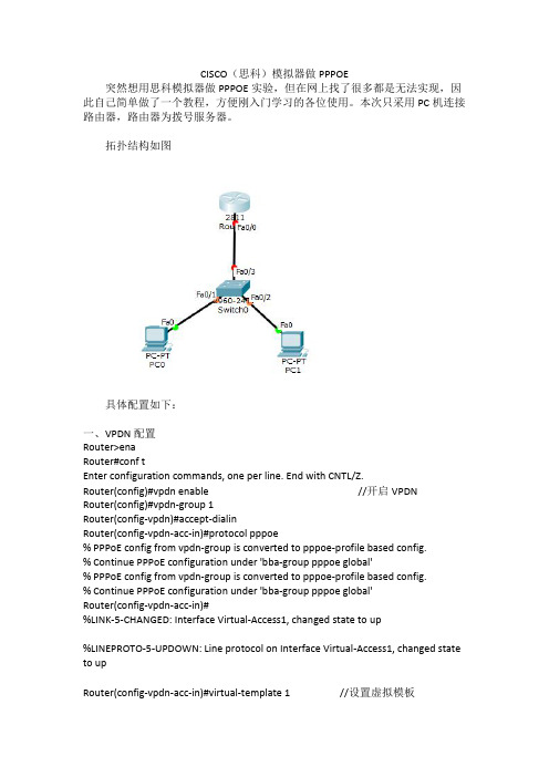
CISCO(思科)模拟器做PPPOE突然想用思科模拟器做PPPOE实验,但在网上找了很多都是无法实现,因此自己简单做了一个教程,方便刚入门学习的各位使用。
本次只采用PC机连接路由器,路由器为拨号服务器。
拓扑结构如图具体配置如下:一、VPDN配置Router>enaRouter#conf tEnter configuration commands,one per line.End with CNTL/Z.Router(config)#vpdn enable//开启VPDN Router(config)#vpdn-group1Router(config-vpdn)#accept-dialinRouter(config-vpdn-acc-in)#protocol pppoe%PPPoE config from vpdn-group is converted to pppoe-profile based config.%Continue PPPoE configuration under'bba-group pppoe global'%PPPoE config from vpdn-group is converted to pppoe-profile based config.%Continue PPPoE configuration under'bba-group pppoe global'Router(config-vpdn-acc-in)#%LINK-5-CHANGED:Interface Virtual-Access1,changed state to up%LINEPROTO-5-UPDOWN:Line protocol on Interface Virtual-Access1,changed state to upRouter(config-vpdn-acc-in)#virtual-template1//设置虚拟模板标号可以自定%PPPoE config from vpdn-group is converted to pppoe-profile based config.%Continue PPPoE configuration under'bba-group pppoe global'Router(config-vpdn-acc-in)#exitRouter(config-vpdn)#exitRouter(config)#二、用户密码库Router(config)#username1234password1234//设置拨号账号密码,可以配置多个Router(config)#username admin password adminRouter(config)#三、地址池Router(config)#ip local pool1192.168.1.10192.168.1.100//设置地址池定义地址池名字四、配置模板接口Router(config)#interface virtual-Template1//需为之前定义虚拟模板Router(config-if)#ip unnumbered f0/0Router(config-if)#peer default ip address pool1//需为之前定义的址池名字Router(config-if)#ppp authentication chapAAA:Warning,authentication list default is not defined for PPP.Router(config-if)#exitRouter(config)#五、配置接口Router(config)#interface f0/0//连接PC端(交换机)的接口Router(config-if)#pppoe enableRouter(config-if)#ip address192.168.1.1255.255.255.0Router(config-if)#no shutdownRouter(config-if)#%LINK-5-CHANGED:Interface FastEthernet0/0,changed state to up%LINEPROTO-5-UPDOWN:Line protocol on Interface FastEthernet0/0,changed state to upRouter(config-if)#exitRouter(config)#进行验证:PC0用admin拨号,显示成功查看配置,可以看到分配为IP池最小ip192.168.1.10PC1用1234账户拨号,拨号成功查看配置,为依次ip192.168.1.11。
Cisco路由器配置实例(经典)

实训报告实训一路由基本配置1、实验目的:路由器基本配置及ip设置2、拓扑结构图Router0 fa0/0: 192.168.11.1Fa0/1:192.168.1.1Router1 fa0/0: 192.168.11.2Fa0/1:192.168.2.1Znn1:192.168.1.2Znn2:192.168.2.23、实验步骤Router1Router>en 用户模式进入特权模式Router#conf t 特权模式进入全局模式Enter configuration commands, one per line. End with CNTL/Z.Router(config)#host rznn1 改名字为rznn1rznn1(config)#int fa0/0 进入fa0/0端口rznn1(config-if)#ip add 192.168.11.1 255.255.255.0 设置ip地址rznn1(config-if)#no sh 激活rznn1(config)#int fa0/1rznn1(config-if)#ip add 192.168.1.1 255.255.255.0rznn1(config-if)#no shrznn1(config-if)#exitrznn1(config)#exitrznn1#copy running-config startup-config 保存Destination filename [startup-config]? startup-configrznn1#conf trznn1(config)#enable secret password 222 设置密文rznn1#show ip interface b 显示Interface IP-Address OK? Method Status Protocol FastEthernet0/0 192.168.11.1 YES manual up up FastEthernet0/1 192.168.1.1 YES manual up upVlan1 unassigned YES manual administratively down downrouter 2outer>enRouter#conf tEnter configuration commands, one per line. End with CNTL/Z.Router(config)#host rznn2rznn2(config)#int fa0/0rznn2(config-if)#ip add 192.168.11.2 255.255.255.0rznn2(config-if)#no shrznn2(config)#int fa0/1rznn2(config-if)#ip add 192.168.2.1 255.255.255.0rznn2(config-if)#no shRznn2#copy running-config startup-config 保存Destination filename [startup-config]? startup-configrznn2(config-if)#exitrznn2(config)#exitrznn2#conf trznn2(config)#enable secret 222rznn2#show ip interface bInterface IP-Address OK? Method Status Protocol FastEthernet0/0 192.168.11.2 YES manual up up FastEthernet0/1 192.168.2.1 YES manual up upVlan1 unassigned YES manual administratively down down实训二1、远程登录、密码设置及验证为路由器开设telnet端口,PC机可以远程登陆到Rznn3(Router 1)拓扑结构图Router0:192.168.1.1Pc:192.168.1.2步骤rznn3>rznn3>enrznn3#conf tEnter configuration commands, one per line. End with CNTL/Z.rznn3(config)#no ip domain lookuprznn3(config)#line cons 0rznn3(config-line)#password znnrznn3(config-line)#loginrznn3(config-line)#no exec-trznn3(config-line)#logg syncrznn3(config-line)#exitrznn3(config)#int fa0/0rznn3(config-if)#ip add 192.168.1.1 255.255.255.0rznn3(config-if)#no shrznn3(config-if)#exitrznn3(config)#line vty 0 4 打通五个端口rznn3(config-line)#password cisco 设置密码rznn3(config-line)#login 保存rznn3(config-line)#exit4、测试:实训三命令组1、目的:八条命令(no ip domain lookup\line cons 0\password\login\no exec-t\logg sync\show version\reload\copy running-config startup-config)\show cdp neighbors)2、拓扑结构图Router0 fa0/0: 192.168.11.1Router1 fa0/0: 192.168.11.23、步骤rznn1#conf tEnter configuration commands, one per line. End with CNTL/Z.1、rznn1(config)#no ip domain lookup 取消域名查找转换2、rznn1(config)#line cons 0 打开cons 0端口3、rznn1(config-line)#password znn 设置密码为znnrznn1(config-line)#login 保存rznn1(config-line)#no exec-t 设置永不超时4、rznn1(config-line)#logg sync 产生日志5、rznn1#show version 显示思科路由系统版本信息Cisco IOS Software, 2800 Software (C2800NM-ADVIPSERVICESK9-M), Version 12.4(15)T1, RELEASE SOFTWARE (fc2)Technical Support: /techsupportCopyright (c) 1986-2007 by Cisco Systems, Inc.Compiled Wed 18-Jul-07 06:21 by pt_rel_team6、rznn1#show cdp neighbors 查看路由器连接的相邻路由器的相关信息Capability Codes: R - Router, T - Trans Bridge, B - Source Route BridgeS - Switch, H - Host, I - IGMP, r - Repeater, P - PhoneDevice ID Local Intrfce Holdtme Capability Platform Port IDrznn2 Fas 0/0 139 R C2800 Fas 0/07、rznn1#copy running-config startup-config 保存刚才指令Destination filename [startup-config]? startup-configBuilding configuration...[OK]8、rznn1#reload 重启路由器Proceed with reload? [confirm]System Bootstrap, Version 12.1(3r)T2, RELEASE SOFTWARE (fc1)Copyright (c) 2000 by cisco Systems, Inc.cisco 2811 (MPC860) processor (revision 0x200) with 60416K/5120K bytes of memorySelf decompressing the image :########################################################################## [OK] Restricted Rights Legendrznn1#show ip interface bInterface IP-Address OK? Method Status Protocol FastEthernet0/0 192.168.11.1 YES manual up up FastEthernet0/1 192.168.1.1 YES manual up upVlan1 unassigned YES manual administratively down down9、rznn1(config-if)#ip add 192.168.3.1 255.255.255.0 重置ip地址rznn1#show ip interface bInterface IP-Address OK? Method Status Protocol FastEthernet0/0 192.168.3.1 YES manual up up FastEthernet0/1 192.168.1.1 YES manual up up Vlan1 unassigned YES manual administratively down down实训四发现协议1、实训目的通过发现协议显示路由器相邻路由的端口信息2、拓扑结构Router0:192.168.11.1Router1:fa0/0 192.168.11.2Fa0/1 192.168.12.1Router2:192.168.12.23、步骤R1路由器Router>enRouter#conf tEnter configuration commands, one per line. End with CNTL/Z.Router(config)#host r1r1(config)#int fa0/0r1(config-if)#ip add 192.168.11.1 255.255.255.0r1(config-if)#no sh%LINK-5-CHANGED: Interface FastEthernet0/0, changed state to upr1(config-if)#r1(config-if)#exitr1(config)#exitr1#%SYS-5-CONFIG_I: Configured from console by consoler1#show ip interface bInterface IP-Address OK? Method Status Protocol FastEthernet0/0 192.168.11.1 YES manual up down FastEthernet0/1 unassigned YES manual administratively down downVlan1 unassigned YES manual administratively down downR2 路由器Router>enRouter#conf tEnter configuration commands, one per line. End with CNTL/Z.Router(config)#host r2r2(config)#int fa0/0r2(config-if)#ip add 192.168.11.2 255.255.255.0r2(config-if)#no sh%LINK-5-CHANGED: Interface FastEthernet0/0, changed state to up%LINEPROTO-5-UPDOWN: Line protocol on Interface FastEthernet0/0, changed state to up r2(config-if)#exitr2(config)#exitr2#%SYS-5-CONFIG_I: Configured from console by consoler2#conf tEnter configuration commands, one per line. End with CNTL/Z.r2(config)#int fa0/0r2(config-if)#int fa0/1r2(config-if)#ip add 192.168.12.1 255.255.255.0r2(config-if)#no sh%LINK-5-CHANGED: Interface FastEthernet0/1, changed state to upr2(config-if)#exitr2(config)#exitr2#%SYS-5-CONFIG_I: Configured from console by consoler2#show ip interface bInterface IP-Address OK? Method Status Protocol FastEthernet0/0 192.168.11.2 YES manual up upFastEthernet0/1 192.168.12.1 YES manual up down Vlan1 unassigned YES manual administratively down downR3路由器Router>enRouter#conf tEnter configuration commands, one per line. End with CNTL/Z.Router(config)#host r3r3(config)#int fa0/0r3(config-if)#ip add 192.168.12.2 255.255.255.0r3(config-if)#no sh%LINK-5-CHANGED: Interface FastEthernet0/0, changed state to up%LINEPROTO-5-UPDOWN: Line protocol on Interface FastEthernet0/0, changed state to up r3(config-if)#exitr3(config)#exitr3#%SYS-5-CONFIG_I: Configured from console by consoler3#show ip interface bInterface IP-Address OK? Method Status Protocol FastEthernet0/0 192.168.12.2 YES manual up up FastEthernet0/1 unassigned YES manual administratively down downVlan1 unassigned YES manual administratively down downR1发现邻居r1#show cdp neighborsCapability Codes: R - Router, T - Trans Bridge, B - Source Route BridgeS - Switch, H - Host, I - IGMP, r - Repeater, P - PhoneDevice ID Local Intrfce Holdtme Capability Platform Port IDr2 Fas 0/0 165 R C2800 Fas 0/0R2发现邻居r2#show cdp neighborsCapability Codes: R - Router, T - Trans Bridge, B - Source Route BridgeS - Switch, H - Host, I - IGMP, r - Repeater, P - PhoneDevice ID Local Intrfce Holdtme Capability Platform Port IDr1 Fas 0/0 176 R C1841 Fas 0/0r3 Fas 0/1 130 R C1841 Fas 0/0R3发现邻居r3#show cdp neighborsCapability Codes: R - Router, T - Trans Bridge, B - Source Route BridgeS - Switch, H - Host, I - IGMP, r - Repeater, P - PhoneDevice ID Local Intrfce Holdtme Capability Platform Port IDr2 Fas 0/0 166 R C2800 Fas 0/14、总结show 命令(1)show ip interface b (显示端口ip信息)(2)show version (显示ios版本信息)(3)show running-config (显示刚才使用的命令配置信息)(4)show cdp neighbors (显示发现邻居直连设备信息)(5)show interface (显示所有端口详细信息)实训五静态路由1、实验目的:将不同网段的网络配通(ip route)Ip route语法:ip route 目标地址子网掩码相邻路由器接口地址Show ip route2、试验拓扑:Router0:192.168.11.1Router1:fa0/0 192.168.11.2Fa0/1 192.168.12.1Router2:192.168.12.23、实验步骤:Router1Router>enRouter#conf tRouter(config)#host r1r1(config)#int fa0/0r1(config-if)#ip add 192.168.11.1 255.255.255.0r1(config-if)#no sh%LINK-5-CHANGED: Interface FastEthernet0/0, changed state to upr1(config-if)#exitr1(config)#exitr1#show ip interface bInterface IP-Address OK? Method Status ProtocolFastEthernet0/0 192.168.11.1 YES manual up downFastEthernet0/1 unassigned YES manual administratively down downVlan1 unassigned YES manual administratively down downr1#%LINEPROTO-5-UPDOWN: Line protocol on Interface FastEthernet0/0, changed state to up r1#ping 192.168.12.1Type escape sequence to abort.Sending 5, 100-byte ICMP Echos to 192.168.12.1, timeout is 2 seconds:.....Success rate is 0 percent (0/5)r1#conf tEnter configuration commands, one per line. End with CNTL/Z.r1(config)#ip route 192.168.12.0 255.255.255.0 192.168.11.2r1(config)#exitr1#ping 192.168.12.1Type escape sequence to abort.Sending 5, 100-byte ICMP Echos to 192.168.12.1, timeout is 2 seconds:Success rate is 100 percent (5/5), round-trip min/avg/max = 31/31/32 msr1#ping 192.168.12.2Type escape sequence to abort.Sending 5, 100-byte ICMP Echos to 192.168.12.2, timeout is 2 seconds:.....Success rate is 0 percent (0/5)r1#ping 192.168.12.2Type escape sequence to abort.Sending 5, 100-byte ICMP Echos to 192.168.12.2, timeout is 2 seconds:Success rate is 100 percent (5/5), round-trip min/avg/max = 47/62/78 msr1#show ip routeCodes: C - connected, S - static, I - IGRP, R - RIP, M - mobile, B - BGPD - EIGRP, EX - EIGRP external, O - OSPF, IA - OSPF inter areaN1 - OSPF NSSA external type 1, N2 - OSPF NSSA external type 2E1 - OSPF external type 1, E2 - OSPF external type 2, E - EGPi - IS-IS, L1 - IS-IS level-1, L2 - IS-IS level-2, ia - IS-IS inter area* - candidate default, U - per-user static route, o - ODRP - periodic downloaded static routeGateway of last resort is not setC 192.168.11.0/24 is directly connected, FastEthernet0/0S 192.168.12.0/24 [1/0] via 192.168.11.2Router3Router>enRouter#conf tEnter configuration commands, one per line. End with CNTL/Z.Router(config)#host r3r3(config)#int fa0/0r3(config-if)#ip add 192.168.12.2 255.255.255.0r3(config-if)#no sh%LINK-5-CHANGED: Interface FastEthernet0/0, changed state to up%LINEPROTO-5-UPDOWN: Line protocol on Interface FastEthernet0/0, changed state to up r3(config-if)#exitr3(config)#exitr3#%SYS-5-CONFIG_I: Configured from console by consoler3#show ip interface bInterface IP-Address OK? Method Status Protocol FastEthernet0/0 192.168.12.2 YES manual up up FastEthernet0/1 unassigned YES manual administratively down downVlan1 unassigned YES manual administratively down downr3#conf tEnter configuration commands, one per line. End with CNTL/Z.r3(config)#ip route 192.168.11.0 255.255.255.0 192.168.12.1r3(config)#exitr3#ping 192.168.11.2Type escape sequence to abort.Sending 5, 100-byte ICMP Echos to 192.168.11.2, timeout is 2 seconds:Success rate is 100 percent (5/5), round-trip min/avg/max = 31/31/32 msr3#ping 192.168.11.1Type escape sequence to abort.Sending 5, 100-byte ICMP Echos to 192.168.11.1, timeout is 2 seconds:Success rate is 100 percent (5/5), round-trip min/avg/max = 62/62/63 msr3#show ip routeCodes: C - connected, S - static, I - IGRP, R - RIP, M - mobile, B - BGPD - EIGRP, EX - EIGRP external, O - OSPF, IA - OSPF inter areaN1 - OSPF NSSA external type 1, N2 - OSPF NSSA external type 2i - IS-IS, L1 - IS-IS level-1, L2 - IS-IS level-2, ia - IS-IS inter area* - candidate default, U - per-user static route, o - ODRP - periodic downloaded static routeGateway of last resort is not setS 192.168.11.0/24 [1/0] via 192.168.12.1C 192.168.12.0/24 is directly connected, FastEthernet0/04、默认路由Route 1r1>enr1#conf tEnter configuration commands, one per line. End with CNTL/Z.r1(config)#no ip route 192.168.12.0 255.255.255.0 192.168.11.2%No matching route to deleter1(config)#exitr1#%SYS-5-CONFIG_I: Configured from console by consoler1#show ip routeCodes: C - connected, S - static, I - IGRP, R - RIP, M - mobile, B - BGPD - EIGRP, EX - EIGRP external, O - OSPF, IA - OSPF inter areaN1 - OSPF NSSA external type 1, N2 - OSPF NSSA external type 2E1 - OSPF external type 1, E2 - OSPF external type 2, E - EGPi - IS-IS, L1 - IS-IS level-1, L2 - IS-IS level-2, ia - IS-IS inter area* - candidate default, U - per-user static route, o - ODRP - periodic downloaded static routeGateway of last resort is not setC 192.168.11.0/24 is directly connected, FastEthernet0/0r1#conf tEnter configuration commands, one per line. End with CNTL/Z.r1(config)#ip route 0.0.0.0 0.0.0.0 192.168.11.2r1(config)#exitr1#%SYS-5-CONFIG_I: Configured from console by consoler1#show ip routeCodes: C - connected, S - static, I - IGRP, R - RIP, M - mobile, B - BGPD - EIGRP, EX - EIGRP external, O - OSPF, IA - OSPF inter areaN1 - OSPF NSSA external type 1, N2 - OSPF NSSA external type 2i - IS-IS, L1 - IS-IS level-1, L2 - IS-IS level-2, ia - IS-IS inter area* - candidate default, U - per-user static route, o - ODRP - periodic downloaded static routeGateway of last resort is 192.168.11.2 to network 0.0.0.0C 192.168.11.0/24 is directly connected, FastEthernet0/0S* 0.0.0.0/0 [1/0] via 192.168.11.2r1#ping 192.168.12.1Type escape sequence to abort.Sending 5, 100-byte ICMP Echos to 192.168.12.1, timeout is 2 seconds:Success rate is 100 percent (5/5), round-trip min/avg/max = 16/28/31 msr1#ping 192.168.12.2Type escape sequence to abort.Sending 5, 100-byte ICMP Echos to 192.168.12.2, timeout is 2 seconds: Success rate is 100 percent (5/5), round-trip min/avg/max = 62/62/63 msRoute 3r1>enr1#conf tEnter configuration commands, one per line. End with CNTL/Z.r1(config)#no ip route 192.168.12.0 255.255.255.0 192.168.11.2%No matching route to deleter1(config)#exitr1#%SYS-5-CONFIG_I: Configured from console by consoler1#show ip routeCodes: C - connected, S - static, I - IGRP, R - RIP, M - mobile, B - BGPD - EIGRP, EX - EIGRP external, O - OSPF, IA - OSPF inter areaN1 - OSPF NSSA external type 1, N2 - OSPF NSSA external type 2E1 - OSPF external type 1, E2 - OSPF external type 2, E - EGPi - IS-IS, L1 - IS-IS level-1, L2 - IS-IS level-2, ia - IS-IS inter area* - candidate default, U - per-user static route, o - ODRP - periodic downloaded static routeGateway of last resort is not setC 192.168.11.0/24 is directly connected, FastEthernet0/0r1#conf tEnter configuration commands, one per line. End with CNTL/Z.r1(config)#ip route 0.0.0.0 0.0.0.0 192.168.11.2r1(config)#exitr1#%SYS-5-CONFIG_I: Configured from console by consoler1#show ip routeCodes: C - connected, S - static, I - IGRP, R - RIP, M - mobile, B - BGPD - EIGRP, EX - EIGRP external, O - OSPF, IA - OSPF inter areaN1 - OSPF NSSA external type 1, N2 - OSPF NSSA external type 2E1 - OSPF external type 1, E2 - OSPF external type 2, E - EGPi - IS-IS, L1 - IS-IS level-1, L2 - IS-IS level-2, ia - IS-IS inter area* - candidate default, U - per-user static route, o - ODRP - periodic downloaded static routeGateway of last resort is 192.168.11.2 to network 0.0.0.0C 192.168.11.0/24 is directly connected, FastEthernet0/0S* 0.0.0.0/0 [1/0] via 192.168.11.2r3#ping 192.168.11.1Type escape sequence to abort.Sending 5, 100-byte ICMP Echos to 192.168.11.1, timeout is 2 seconds: Success rate is 100 percent (5/5), round-trip min/avg/max = 62/62/63 ms实训六动态路由RIP 协议1、实验目的使用配置动态路由启动Rip协议使用到的命令(router rip/network/show ip protocols/show ip route)2、实验拓扑R1 fa0/0 192.168.11.1R2 fa0/0 192.168.11.2fa0/1 192.168.12.1R3 fa0/0 192.168.12.23、实验步骤R1Router>enRouter#conf tEnter configuration commands, one per line. End with CNTL/Z. Router(config)#host r1r1(config)#int fa0/0r1(config-if)#ip add 192.168.11.1 255.255.255.0r1(config-if)#no shr1(config-if)#exitr1(config)#router ripr1(config-router)#network 192.168.11.0r1(config-router)#exitr1(config)#exitr1#%SYS-5-CONFIG_I: Configured from console by consoleR2Router>enRouter#conf tEnter configuration commands, one per line. End with CNTL/Z. Router(config)#host r2r2(config)#int fa0/0r2(config-if)#ip add 192.168.11.2 255.255.255.0r2(config-if)#no shr2(config-if)#exitr2(config)#int fa0/1r2(config-if)#ip add 192.168.12.1 255.255.255.0r2(config-if)#no shr2(config-if)#exitr2(config)#router ripr2(config-router)#network 192.168.11.0r2(config-router)#network 192.168.12.0r2(config-router)#exitr2(config)#exitr2#R3Router>enRouter#conf tEnter configuration commands, one per line. End with CNTL/Z. Router(config)#host r3r3(config)#int fa0/0r3(config-if)#ip add 192.168.12.2 255.255.255.0r3(config-if)#no shr3(config-if)#exitr3(config)#router ripr3(config-router)#network 192.168.12.0r3(config-router)#exitr3(config)#exitr3#%SYS-5-CONFIG_I: Configured from console by console4、实验测试R1r1#show ip protocolsRouting Protocol is "rip"Sending updates every 30 seconds, next due in 10 secondsInvalid after 180 seconds, hold down 180, flushed after 240 Outgoing update filter list for all interfaces is not setIncoming update filter list for all interfaces is not set Redistributing: ripDefault version control: send version 1, receive any version Interface Send Recv Triggered RIP Key-chain FastEthernet0/0 1 2 1Automatic network summarization is in effectMaximum path: 4Routing for Networks:192.168.11.0Passive Interface(s):Routing Information Sources:Gateway Distance Last UpdateDistance: (default is 120)r1#show ip routeCodes: C - connected, S - static, I - IGRP, R - RIP, M - mobile, B - BGPD - EIGRP, EX - EIGRP external, O - OSPF, IA - OSPF inter areaN1 - OSPF NSSA external type 1, N2 - OSPF NSSA external type 2E1 - OSPF external type 1, E2 - OSPF external type 2, E - EGPi - IS-IS, L1 - IS-IS level-1, L2 - IS-IS level-2, ia - IS-IS inter area* - candidate default, U - per-user static route, o - ODRP - periodic downloaded static routeGateway of last resort is not setC 192.168.11.0/24 is directly connected, FastEthernet0/0R 192.168.12.0/24 [120/1] via 192.168.11.2, 00:00:24, FastEthernet0/0 r1#ping 192.168.12.0Type escape sequence to abort.Sending 5, 100-byte ICMP Echos to 192.168.12.0, timeout is 2 seconds: Success rate is 100 percent (5/5), round-trip min/avg/max = 31/31/32 msR2r2#show ip protocolsRouting Protocol is "rip"Sending updates every 30 seconds, next due in 21 secondsInvalid after 180 seconds, hold down 180, flushed after 240Outgoing update filter list for all interfaces is not setIncoming update filter list for all interfaces is not setRedistributing: ripDefault version control: send version 1, receive any versionInterface Send Recv Triggered RIP Key-chain FastEthernet0/0 1 2 1FastEthernet0/1 1 2 1Automatic network summarization is in effectMaximum path: 4Routing for Networks:192.168.11.0192.168.12.0Passive Interface(s):Routing Information Sources:Gateway Distance Last UpdateDistance: (default is 120)r2#show ip routeCodes: C - connected, S - static, I - IGRP, R - RIP, M - mobile, B - BGPD - EIGRP, EX - EIGRP external, O - OSPF, IA - OSPF inter areaN1 - OSPF NSSA external type 1, N2 - OSPF NSSA external type 2E1 - OSPF external type 1, E2 - OSPF external type 2, E - EGPi - IS-IS, L1 - IS-IS level-1, L2 - IS-IS level-2, ia - IS-IS inter area* - candidate default, U - per-user static route, o - ODRP - periodic downloaded static routeGateway of last resort is not setC 192.168.11.0/24 is directly connected, FastEthernet0/0C 192.168.12.0/24 is directly connected, FastEthernet0/1R3r3#show ip protocolsRouting Protocol is "rip"Sending updates every 30 seconds, next due in 15 secondsInvalid after 180 seconds, hold down 180, flushed after 240Outgoing update filter list for all interfaces is not setIncoming update filter list for all interfaces is not setRedistributing: ripDefault version control: send version 1, receive any versionInterface Send Recv Triggered RIP Key-chain FastEthernet0/0 1 2 1Automatic network summarization is in effectMaximum path: 4Routing for Networks:192.168.12.0Passive Interface(s):Routing Information Sources:Gateway Distance Last UpdateDistance: (default is 120)r3#show ip routeCodes: C - connected, S - static, I - IGRP, R - RIP, M - mobile, B - BGPD - EIGRP, EX - EIGRP external, O - OSPF, IA - OSPF inter areaN1 - OSPF NSSA external type 1, N2 - OSPF NSSA external type 2E1 - OSPF external type 1, E2 - OSPF external type 2, E - EGPi - IS-IS, L1 - IS-IS level-1, L2 - IS-IS level-2, ia - IS-IS inter area* - candidate default, U - per-user static route, o - ODRP - periodic downloaded static routeGateway of last resort is not setR 192.168.11.0/24 [120/1] via 192.168.12.1, 00:00:04, FastEthernet0/0 C 192.168.12.0/24 is directly connected, FastEthernet0/0r3#ping 192.168.11.0Type escape sequence to abort.Sending 5, 100-byte ICMP Echos to 192.168.11.0, timeout is 2 seconds: Success rate is 100 percent (5/5), round-trip min/avg/max = 31/31/32 ms实训七负载平衡试训目的实现负载平衡实训拓扑R1 fa0/0 192.168.11.1R2 eth0/0/0 192.168.11.2Fa0/0 192.168.12.1Fa0/0 192.168.13.1R3 fa0/0 192.168.12.2Fa0/1 192.168.14.1R4 fa0/0 192.168.13.2Fa0/1 192.168.15.1R5 fa0/0 192.168.14.2Fa0/1 192.168.15.2实训步骤(R1 )r1>enR1#conf tR1(config)#ip route 0.0.0.0 0.0.0.0 192.168.11.2R1(config)#exitr1#show ip routeCodes: C - connected, S - static, I - IGRP, R - RIP, M - mobile, B - BGPD - EIGRP, EX - EIGRP external, O - OSPF, IA - OSPF inter areaN1 - OSPF NSSA external type 1, N2 - OSPF NSSA external type 2E1 - OSPF external type 1, E2 - OSPF external type 2, E - EGPi - IS-IS, L1 - IS-IS level-1, L2 - IS-IS level-2, ia - IS-IS inter area* - candidate default, U - per-user static route, o - ODRP - periodic downloaded static routeGateway of last resort is 192.168.11.2 to network 0.0.0.0C 192.168.11.0/24 is directly connected, FastEthernet0/0S* 0.0.0.0/0 [1/0] via 192.168.11.2(R2)r2>enr2(config)#ip route 0.0.0.0 0.0.0.0 192.168.12.2r2(config)#ip route 0.0.0.0 0.0.0.0 192.168.13.2r2(config)#exitr2#%SYS-5-CONFIG_I: Configured from console by consoles% Ambiguous command: "s"r2#show ip routeCodes: C - connected, S - static, I - IGRP, R - RIP, M - mobile, B - BGPD - EIGRP, EX - EIGRP external, O - OSPF, IA - OSPF inter areaN1 - OSPF NSSA external type 1, N2 - OSPF NSSA external type 2E1 - OSPF external type 1, E2 - OSPF external type 2, E - EGPi - IS-IS, L1 - IS-IS level-1, L2 - IS-IS level-2, ia - IS-IS inter area* - candidate default, U - per-user static route, o - ODRP - periodic downloaded static routeGateway of last resort is 192.168.12.2 to network 0.0.0.0C 192.168.11.0/24 is directly connected, Ethernet0/0/0C 192.168.12.0/24 is directly connected, FastEthernet0/0C 192.168.13.0/24 is directly connected, FastEthernet0/1S* 0.0.0.0/0 [1/0] via 192.168.12.2[1/0] via 192.168.13.2(R3)r3>enr3#conf tEnter configuration commands, one per line. End with CNTL/Z.r3(config)#ip route 0.0.0.0 0.0.0.0 192.168.12.1r3(config)#exitr3#%SYS-5-CONFIG_I: Configured from console by consoler3#show ip routeCodes: C - connected, S - static, I - IGRP, R - RIP, M - mobile, B - BGPD - EIGRP, EX - EIGRP external, O - OSPF, IA - OSPF inter areaN1 - OSPF NSSA external type 1, N2 - OSPF NSSA external type 2E1 - OSPF external type 1, E2 - OSPF external type 2, E - EGPi - IS-IS, L1 - IS-IS level-1, L2 - IS-IS level-2, ia - IS-IS inter area* - candidate default, U - per-user static route, o - ODRP - periodic downloaded static routeGateway of last resort is 192.168.12.1 to network 0.0.0.0C 192.168.12.0/24 is directly connected, FastEthernet0/0C 192.168.14.0/24 is directly connected, FastEthernet0/1S* 0.0.0.0/0 [1/0] via 192.168.12.1(R4)r4>enr4#conf tEnter configuration commands, one per line. End with CNTL/Z.r4(config)#ip route 0.0.0.0 0.0.0.0 192.168.13.1r4(config)#exitr4#%SYS-5-CONFIG_I: Configured from console by consoler4#show ip routeCodes: C - connected, S - static, I - IGRP, R - RIP, M - mobile, B - BGPD - EIGRP, EX - EIGRP external, O - OSPF, IA - OSPF inter areaN1 - OSPF NSSA external type 1, N2 - OSPF NSSA external type 2E1 - OSPF external type 1, E2 - OSPF external type 2, E - EGPi - IS-IS, L1 - IS-IS level-1, L2 - IS-IS level-2, ia - IS-IS inter area* - candidate default, U - per-user static route, o - ODRP - periodic downloaded static routeGateway of last resort is 192.168.13.1 to network 0.0.0.0C 192.168.13.0/24 is directly connected, FastEthernet0/0C 192.168.15.0/24 is directly connected, FastEthernet0/1S* 0.0.0.0/0 [1/0] via 192.168.13.1(R5)r5>enr5#conf tEnter configuration commands, one per line. End with CNTL/Z.r5(config)#ip route 0.0.0.0 0.0.0.0 192.168.14.1r5(config)#ip route 0.0.0.0 0.0.0.0 192.168.15.1r5(config)#exitr5#%SYS-5-CONFIG_I: Configured from console by consoler5#show ip routeCodes: C - connected, S - static, I - IGRP, R - RIP, M - mobile, B - BGPD - EIGRP, EX - EIGRP external, O - OSPF, IA - OSPF inter areaN1 - OSPF NSSA external type 1, N2 - OSPF NSSA external type 2E1 - OSPF external type 1, E2 - OSPF external type 2, E - EGPi - IS-IS, L1 - IS-IS level-1, L2 - IS-IS level-2, ia - IS-IS inter area* - candidate default, U - per-user static route, o - ODRP - periodic downloaded static routeGateway of last resort is 192.168.14.1 to network 0.0.0.0C 192.168.14.0/24 is directly connected, FastEthernet0/0C 192.168.15.0/24 is directly connected, FastEthernet0/1S* 0.0.0.0/0 [1/0] via 192.168.14.1[1/0] via 192.168.15.1实训测试(R1)r1#ping 192.168.14.1Type escape sequence to abort.Sending 5, 100-byte ICMP Echos to 192.168.14.1, timeout is 2 seconds:Success rate is 100 percent (5/5), round-trip min/avg/max = 62/84/94 ms (R5)r5#ping 192.168.11.1Type escape sequence to abort.Sending 5, 100-byte ICMP Echos to 192.168.11.1, timeout is 2 seconds: Success rate is 100 percent (5/5), round-trip min/avg/max = 79/91/94 ms实训八DHCP 协议配置实训目的全网配通实训拓扑Fa0/0 192.168.11.1Fa0/1 192.168.12.1实训步骤Router>enRouter#conf tEnter configuration commands, one per line. End with CNTL/Z.Router(config)#host r1r1(config)#int fa0/0r1(config-if)#ip add 192.168.11.1 255.255.255.0r1(config-if)#no shr1(config-if)#exitr1(config)#int fa0/1r1(config-if)#ip add 192.168.12.1 255.255.255.0r1(config-if)#no shr1(config-if)#exitr1(config)#ip dhcp pool znn //配置一个根地址池znnr1(dhcp-config)#network 192.168.11.0 255.255.255.0 //为所有客户机动态分配的地址段r1(dhcp-config)#default-router 192.168.11.1 //为客户机配置默认的网关r1(dhcp-config)#dns-server 192.168.11.1 //为客户机配置DNS服务器r1(dhcp-config)#exitr1(config)#ip dhcp pool znn1r1(dhcp-config)#network 192.168.12.0 255.255.255.0r1(dhcp-config)#default-router 192.168.12.1r1(dhcp-config)#dns-server 192.168.12.1r1(dhcp-config)#exit。
华赛防火墙PPPOE拨号配置实例
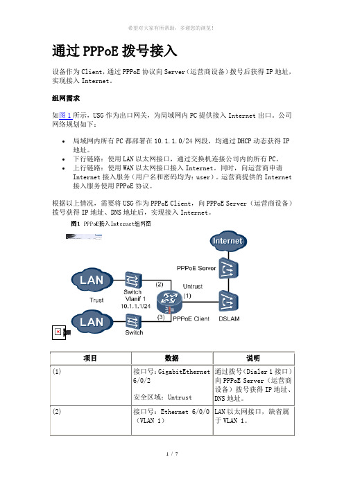
通过PPPoE拨号接入设备作为Client,通过PPPoE协议向Server(运营商设备)拨号后获得IP地址,实现接入Internet。
组网需求如图1所示,USG作为出口网关,为局域网内PC提供接入Internet出口。
公司网络规划如下:•局域网内所有PC都部署在10.1.1.0/24网段,均通过DHCP动态获得IP 地址。
•下行链路:使用LAN以太网接口,通过交换机连接公司内的所有PC。
•上行链路:使用WAN以太网接口接入Internet。
同时,向运营商申请Internet接入服务(用户名和密码均为:user)。
运营商提供的Internet接入服务使用PPPoE协议。
根据以上情况,需要将USG作为PPPoE Client,向PPPoE Server(运营商设备)拨号获得IP地址、DNS地址后,实现接入Internet。
项目数据说明(1) 接口号:GigabitEthernet6/0/2安全区域:Untrust通过拨号(Dialer 1接口)向PPPoE Server(运营商设备)拨号获得IP地址、DNS地址。
(2) 接口号:Ethernet 6/0/0(VLAN 1)LAN以太网接口,缺省属于VLAN 1。
配置思路1.配置下行链路。
在Vlanif 1上开启DHCP Server服务,为PC动态分配IP地址,指定PC 获得的网关和DNS服务器地址均为Vlanif 1接口。
PC上网通常需要解析域名,这就需要为其指定DNS服务器地址。
本例中采用USG作为DNS中继设备。
2.配置上行链路。
3.将接口加入到安全区域,并在域间配置NAT和包过滤。
将连接公司局域网的接口加入到高安全等级的区域(Trust),将连接Internet的上行接口加入到低安全等级的区域(Untrust)。
局域网内通常使用私网地址,访问Internet时,必须配置NAT。
本例中,因为上行接口通过拨号获得IP地址,每次拨号获得的IP地址可能不一样,所以采用Easy IP。
Cisco路由器的ADSL modem配置详解.doc

Cisco路由器的ADSL modem配置详解Cisco路由器的ADSL modem配置详解具体的方法路由器接入ADSL配置详解1、Cisco路由器连接ADSL modem的PPPoE配置:说明:此案例为北京电信adsl PPPoE接入,需要使用一个普通adsl modem和一台cisco 2500路由器(双以太口),IOS 12.2(15)T,能够实现局域网共享上网.此案例配置共分7步:第一步:配置vpdn vpdn e1、Cisco路由器连接ADSL modem的PPPoE配置:说明:此案例为北京电信adsl PPPoE接入,需要使用一个普通adsl modem和一台cisco 2500路由器(双以太口),IOS 12.2(15)T,能够实现局域网共享上网.此案例配置共分7步:第一步:配置vpdnvpdn enable(启用路由器的虚拟专用拨号网络---d)vpdn-group office(建立一个vpdn组,)request-dialin(初始化一个d tunnel,建立一个请求拨入的vpdn子组,)protocol pppoe(vpdn子组使用pppoe建立会话隧道)第二步: 配置路由器连接adsl modem的接口interface Ethernet1no ip addresspppoe enable允许以太接口运行pppoepppoe-client dial-pool-number 1将以太接口的pppoe拨号客户端加入拨号池1第三步:配置逻辑拨号接口:interface Dialer1ip address negotiated从adsl服务商动态协商得到ip地址ip nat outside为该接口启用NATencapsulation ppp为该接口封装ppp协议dialer pool 1该接口使用1号拨号池进行拨号dialer-group 1该命令对于pppoe是意义不大的ppp authentication pap callin启用ppp pap验证ppp pap sent-username xxxxxxx password 0 yyyyyyy使用已经申请的用户名和口令第四步:配置内部网络接口interface Ethernet0(内部网络接口)ip address 10.1.1.1 255.255.255.0ip nat inside为该接口启用NAT第五步:配置路由器为内部网络主机提供dhcp服务ip dhcp excluded-address 10.1.1.1ip dhcp pool ABCimport all(导入dns和wins server)network 10.1.1.0 255.255.255.0default-router 10.1.1.1第六步:配置NAT:access-list 1 permit 10.1.1.0 0.0.0.255cc第七步:配置缺省路由ip route 0.0.0.0 0.0.0.0 Dialer12、Cisco路由器连接ADSL WIC卡之PPPoE配置解:!vpdn enableno vpdn logging =由于ADSL的PPPoE应用是通过虚拟拨号来实现的所以在路由器中需要使用VPDN的功能!vpdn-group pppoe =为PPPoE启动了VPDN的进程request-dialinprotocol pppoe =设置拨号协议为PPPoE!interface FastEthernet0 =设置公司内部网络地址ip address 192.168.0.1 255.255.255.0ip nat inside =为启用NAT转换,设置Fast ethernet端口为内部网络,从内部网络收到的数据的原地址转换为公网地址!interface ATM0/0 =设置ADSL端口no ip address =请不要设置地址no atm ilmi-keepalivebundle-enabledsl operating-mode autohold-queue 224 ininterface ATM0/0.1 point-to-point =ADSL的通讯依靠VC,所以必须设定点到点VCpvc 8/81 =设置PVC的相关参数,即VCI和VPI的值,如果不清楚请向局端查询pppoe-client dial-pool-number 1 =PPPoE拨号进程使用了常规的拨号进程,这里引用了dialer-pool 1!interface Dialer1 =建立一个虚拟拨号端口ip address negotiated =由于局端提供动态地址,所以必须设定地址为协商获得ip mtu 1492 =修改mtu值以适用于ADSL网络ip nat outside =为启用NAT转换,设置该端口为外部网络encapsulation ppp =使用PPP的帧格式dialer pool 1ppp authentication pap callin =设置拨号的验证方式为papppp pap sent vip pass vip =发送用户名和密码ip nat inside source list 1 interface Dialer1 overload =设置了NAT 的转换方式,使用了dialer 1端口的动态地址!ip classlessip route 0.0.0.0 0.0.0.0 dialer1 =将所有不可路由的数据报转发给ADSL线路,设定缺省路由no ip http server!access-list 1 permit 192.168.0.0 0.0.0.255-------------------------------------Cisco路由器连接ADSL modem的PPPoE配置:hostname bjsite!ip subnet-zerono ip domain-lookup!vpdn enableno vpdn logging!vpdn-group 1request-dialinprotocol pppoe!interface Ethernet0/0ip address 192.168.0.1 255.255.255.0 ip nat inside!!!!interface Ethernet0/1no ip addresspppoe enablepppoe-client dial-pool-number 1 !interface Dialer1ip address negotiatedip nat outsideip mtu 1492encapsulation pppdialer pool 1dialer-group 1ppp authentication papppp pap sent-username dg48907653@163.gd password xxxxxxxx !ip classlessno ip http server!dialer-list 1 protocol ip permitip nat inside source list 1 interface Dialer1 overloadip route 0.0.0.0 0.0.0.0 dialer1access-list 1 permit 192.168.0.0 0.0.0.255!line con 0exec-timeout 0 0transport input noneline vty 0 4login!endCisco路由器连接ADSL WIC卡之PPPoE配置:vpdn-group pppoerequest-dialin!--- we are the PPPoE client requesting to establish !--- a session with the aggregation unit (6400 NRP). protocol pppoe!!--- internal Ethernet network.!interface FastEthernet0ip address 10.92.1.182 255.255.255.0ip nat inside!--- DSL interface.!interface ATM0no ip addressno atm ilmi-keepalivebundle-enabledsl operating-mode autohold-queue 224 in!--- All defaults.!--- PPPoE runs on top of AAL5SNAP, but the !--- encap aal5snap command is not used.!interface ATM0.1 point-to-pointpvc 1/1pppoe-client dial-pool-number 1!--- pvc 1/1 is an example value that must be changed!--- to match the value used by the ISP.!!--- The PPPoE client code ties into a dialer interface upon!--- which a virtual-access interface is cloned.!interface Dialer1ip address negotiatedip mtu 1492!--- Ethernet MTU default = 1500 (1492 + PPPoE headers = 1500) ip nat outsideencapsulation pppdialer pool 1!--- Ties to atm interface.ppp authentication chap callinppp chap hostname usernameppp chap password password!!--- The ISP will instruct you regarding!--- the type of authentication to use.!--- To change from PPP CHAP to PPP PAP, !--- replace the following three lines:!--- ppp authentication chap callin!--- ppp chap hostname username!--- ppp chap password password!--- with the following two lines:!--- ppp authentication pap callin!--- ppp pap sent-username username password password !--- For NAT we are going to overload on the Dialer1!--- interface and add a default route out!--- since dialer ip address can change.ip nat inside source list 1 interface Dialer1 overloadip classlessip route 0.0.0.0 0.0.0.0 dialer1no ip http server!access-list 1 permit 10.92.1.0 0.0.0.255-------------------------------------------用cisco路由器做PPPoE Server端配置enconf thostname Adsl_walkbirdusername walkbird password walkbird vpdn enablevpdn-group pppoeaccept-dialinprotocol pppoevirtual-template 1exitexitinterface ethernet 0/0pppoe enableno shutdowninterface virtual-template 1mtu 1492 //PPP头部最大传输单元ip unnumbered loopback //借用地址peer default ip address pool pppoe_ip_poolencapsulation pppppp authentication papexitip local pool pppoe_ip_pool 11.11.11.10 11.11.11.100 interface lookback0ip address 1.1.1.1 255.255.255.0no shutdownexit三、实验测试sh ip routesh ip int briefdebug pppoe eventsh ip int dialer 1看了Cisco路由器的ADSL modem配置详解还想看:1.了解Cisco路由器的ADSL modem实现上网设置2.d link路由器怎么设置3.怎么设置cisco 2500路由器ADSL接入4.思科路由器接入ADSL怎么配置5.思科路由器连接ADSL怎么配置PPPoECisco路由器交换机防火墙配置命令详解Cisco路由器交换机防火墙配置命令详解cisco思科公司是全球领先的网络解决方案供应商,其出产的设备配置起来也跟别的不太一样,下面是Cisco路由器交换机防火墙配置命令详解,希望对你有所帮助。
- 1、下载文档前请自行甄别文档内容的完整性,平台不提供额外的编辑、内容补充、找答案等附加服务。
- 2、"仅部分预览"的文档,不可在线预览部分如存在完整性等问题,可反馈申请退款(可完整预览的文档不适用该条件!)。
- 3、如文档侵犯您的权益,请联系客服反馈,我们会尽快为您处理(人工客服工作时间:9:00-18:30)。
1、ADSL PPPoE Client 配置
第一种方法:用PC上创建PPPOE客户端。
第二种方法:用CISCO路由器的以太口进行PPPOE拨号:非固定IP
配置模板:
en
confit t
vpdn enable
vpdn-group pppoe
!
line con 0
exec-timeout 0 0
transport input none
line vty 0 4
login
!
end
案例二
经典思科1841ADSL的成功设置+DHCP的问题~!急~~!
路由器下面的客户端全是XP。都是设为自动获取IP 地址。
现像是在客户端上IPCONFIG 地址是0。0。0。0
transport input telnet
!
end
cisco1841#
案例三
假设E0接内网,E1接ADSL上外网
第一步:配置vpdn
vpdn enable(启用路由器的虚拟专用拨号网络---vpnd)
vpdn-group office(建立一个vpdn组,)
request-dialin(初始化一个vpnd tunnel,建立一个请求拨入的vpdn子组,)
description $ETH-LAN$$ETH-SW-LAUNCH$$INTF-INFO-FE 0$
ip address 192.168.1.1 255.255.255.0
ip access-group 100 in
ip nat inside
duplex auto
speed auto
no ip http server
! பைடு நூலகம்
dialer-list 1 protocol ip permit
ip nat inside source list 1 interface Dialer1 overload
ip route 0.0.0.0 0.0.0.0 dialer1
access-list 1 permit 192.168.0.0 0.0.0.255
Cisco1841路由器连接ADSL modem的PPPoE配置
案例一
vpdn enable
no vpdn logging
!
!
interface Ethernet0/0
ip address 192.168.0.1 255.255.255.0
ip nat inside
no ip mroute-cache
device.
This feature requires the one-time use of the username "cisco"
with the password "cisco".
Please change these publicly known initial credentials using SDM or the
ip unnumbered loopback //借用地址
peer default ip address pool pppoe_ip_pool
encapsulation ppp
ppp authentication pap
exit
ip local pool pppoe_ip_pool 11.11.11.10 11.11.11.100
!
!
!
!
interface Ethernet0/1
no ip address
pppoe enable
pppoe-client dial-pool-number 1
!
interface Dialer1
ip address negotiated
ip nat outside
ip mtu 1492
2、用cisco路由器做PPPoE Server端配置
en
conf t
hostname Adsl_walkbird
username walkbird password walkbird
vpdn enable
vpdn-group pppoe
accept-dialin
protocol pppoe
!
interface FastEthernet0/1
no ip address
duplex auto
speed auto
pppoe enable
pppoe-client dial-pool-number 1
!
interface Dialer1
ip address negotiated
want to use.
For more information about SDM please follow the instructions in the
QUICK START
GUIDE for your router or go to /go/sdm
-----------------------------------------------------------------------
^C
!
line con 0
timeout login response 200
login local
line aux 0
line vty 0 4
request-dialin
protocol pppoe
exit
exit
interface ethernet 0/0
no ip address
pppoe enable
pppoe-client dial-pool-number 1
no shutdown //把接口打开
encapsulation ppp
no ip mroute-cache
dialer pool 1
dialer-group 1
ppp authentication pap
ppp pap sent-username dg48907653@163.gd password xxxxxxxx
!
ip classless
virtual-template 1
exit
exit
interface ethernet 0/0
pppoe enable
no shutdown
interface virtual-template 1
mtu 1492 //PPP头部最大传输单元
service timestamps log datetime msec
no service password-encryption
service dhcp
!
hostname cisco1841
!
boot-start-marker
boot-end-marker
!
logging buffered 51200 warnings
dns-server 202.106.0.20 202.106.46.151
!
!
no ip domain lookup
ip domain name
ip dhcp-server 192.168.1.1
vpdn enable
vpdn ip udp ignore checksum
IOS CLI.
Here are the Cisco IOS commands.
username <myuser> privilege 15 secret 0 <mypassword>
no username cisco
Replace <myuser> and <mypassword> with the username and password you
ip nat inside source list 1 interface Dialer1 overload
!
access-list 1 permit any
access-list 100 deny
access-list 100 deny
access-list 100 permit ip any any
!
ip classless
ip route 0.0.0.0 0.0.0.0 Dialer1
!
no ip http server
ip http authentication local
ip http timeout-policy idle 5 life 86400 requests 10000
dialer-list 1 protocol ip permit
!
control-plane
!
banner login ^C
-----------------------------------------------------------------------
Cisco Router and Security Device Manager (SDM) is installed on this
exit
interface Dialer1
ip address negotiated
ip mtu 1492
encapsulation ppp
