CTB产品维修手册簿
DocuPrint P115 b维修手册(第一版)无密码
• 使用时请注意,应将手册保管好,避免遗失 或破损。
• 修订和修改信息 当出现设计变更或本维修手册发生修改时,在载 入最新的维修手册之前,将可能作为补充信息, 发行海外技术信息或海外维修公告。
注意
在得知备用零件号码的变更及规 格调整等重要的变更信息后,须 立即反映在本维修手册内的相应 页面。
4.4 Toner和Drum问题故障排除 ..................................................... 1-29 4.4.1 更换新Toner cartridge后,LED显示仍提示更换Toner cartridge ........... 1-29 4.4.2 无法检测到Toner cartridge ........................................... 1-29 4.4.3 无法检测到Toner cartridge ........................................... 1-29
4.4.4 4.4.5 4.4.6
Drum错误 ............................................................ 1-29 无法检测到Drum unit ................................................. 1-30 更换Drum unit (更换新Drum unit后,LED显示仍提示更换Toner cartridge)... 1-30
1-23 1-24 1-24 1-24 1-25 1-25 1-26 1-26
4.2.20 重影 ................................................................ 1-26 4.2.21 图像模糊 ............................................................ 1-27
产品维修手册(13版v4.0)
产品维修手册V4.0一、概述维修是整个生产中一个重要环节,维修的速度与质量关系到整个生产的良品率和生产效率,对一个产品来说发现的不良大部分是焊接不良(SMT波峰焊及补焊)和器件来料不良,所以维修因从这两点入手。
二、维修规范1.1 更换、焊接任何元器件和拨、插连接线时,必须将电源切断,断开电池点,不得断电插拔以免击坏元器件。
1.2 防静电措施(整个维修过程都必须防静电!)a)不得随便用手触摸 IC;b)使用防静电烙铁,电烙铁要接地;c)焊接工必须戴有线防静电手腕。
1.3 更换元器件时,应参照表计物料清单,不得随意更换规格、型号、厂家。
1.4 对于需要重刷程序的维修表计必须查询核对原有订单的程序版本信息,应配烧原有程序不得随意配烧当前最新程序(批量返修重烧程序除外)。
1.5 整表拆解后零部件必须统一放置拆解料盒内。
2.1 焊点检验:a)维修焊接后需检查虚焊、连焊,焊后必须用防静电毛刷清除锡珠。
2.2、元器件检验:a)更换器件之前要确认器件是否坏;b)确认新器件是否与不良器件的物料一致;c)更换器件后再次确认更换物料是否正确。
2.3、维修完毕组装时应倾倒检查表内是否有异物残留,组装完毕需检查拆解料盒内是否有漏装件。
注:在维修之时请严格遵守上述规范三、维修工具及设备万用表、掌机、维修录入掌机、电动起子、恒温电烙铁、三相功率源、三相标准表、电脑、多功讯线、起子、镊子、斜口钳等。
四、故障排查及维修方法(单相)RS485芯片引脚分配图红外接收红外发射计量电路火线电流采样零线电流采样电压采样电源电压测试点路路路五、故障排查及维修方法(三相)RS485芯片引脚分配图A B C零线线线三相SW2L30计量芯片管脚分布图有功灯无功灯跳闸灯备注:单(三)相表计任何故障现象均与主芯片有关联。
2016年福特汽车导入市场的产品保修指南说明书

GC3J 19T201 BA April 2015First PrintingWarranty GuideFord • LincolnLitho in U.S.A.2016 E X P O R T M A R WARRANTY GUIDEK E T SYour satisfaction is our #1goal.If you have any questions or concerns,or are unsatisfied with the service you are receiving,follow these steps:1.Contact your Sales Representative or Service Advisor at your selling/servicing dealership.2.If your inquiry or concern remains unresolved,contact the Sales Manager,Service Manager or Customer Relations Manager.3.If you require assistance or clarification on Ford Motor Company policies or procedures,please contact the Ford Customer Relationship Center.1.Introduction8Ford Motor Company and your selling dealer thank you for selecting one of our quality products.Our commitment to you and your vehicle begins with quality protection and service.When you need warranty repairs,your selling dealer would like you to return to it for that service,but you may also take your vehicle to another Ford Motor Company dealership authorized for warranty repairs. This booklet explains in detail the warranty coverages that apply to your 2016-model car or light truck.If you bought a previously owned2016-model vehicle,you are eligible for any remaining warranty coverages.9QUICK REFERENCE:WARRANTY COVERAGE FOR NORTH AMERICAN PRODUCED VEHICLES INCLUDING E-SERIES,EDGE,ESCAPE,EXPEDITION,EXPLORER,F-150,F-SUPER DUTY,FLEX,FOCUS,FUSION,MKS,MKT,MKX,MKZ,MUSTANG,NAVIGATOR AND TAURUS (EXCLUDES F-650/750)Note:Vehicles listed were accurate at time of duplication but may change without notice and without obligation.This chart gives a general summary of your warranty coverage provided by Ford Motor Company under the New Vehicle Limited Warranty.Please refer to the description of warranty coverage for more specific information.For each type of coverage,the chart shows two measures:•years in service •kilometers/miles drivenThe measure that occurs first determines how long your coverage lasts.For example:Your Bumper to Bumper Coverage lasts for three years -unless you drive more than 60,000kilometers/36,000miles before three years elapse.In that case,your coverage ends at60,000kilometers/36,000miles.For more details on coverage,see:→What is Covered?(page 15)→What is Not Covered?(page17)2.Quick Reference:Warranty Coverage10QUICK REFERENCE:WARRANTY COVERAGE FOR VEHICLES PRODUCED OUTSIDE OF NORTH AMERICA INCLUDING C-MAX,COURIER,ECOSPORT,EU ESCAPE,EVEREST,FALCON,FIESTA,EU FOCUS,EU FUSION,GALAXY,KA,MONDEO,RANGER (NON-N.A.),S-MAX,TRANSIT AND TRANSIT CONNECTNote:The following warranty coverage also applies to all vehicles serviced by Export and Growth Aid &Development distributors Note:Vehicles listed were accurate at time of duplication but may change without notice and without obligation.This chart gives a general summary of your warranty coverage provided by Ford Motor Company under the New Vehicle Limited Warranty.Please refer to the description of warranty coverage for more specific information.For each type of coverage,the chart shows two measures:•years in service •kilometers/miles drivenThe measure that occurs first determines how long your coverage lasts.For example:Your Bumper to Bumper Coverage lasts for three years -unless you drive more than 60,000kilometers/36,000miles before three years elapse.In that case,your coverage ends at60,000kilometers/36,000miles.For more details on coverage,see:→What is Covered?(page 15)→What is Not Covered?(page17)113.Important Information You Should KnowIF YOU NEED CUSTOMER ASSISTANCEYour Ford Motor Company dealer is available to assist you with all your automotive needs.Please follow the procedures outlined on the front page of this booklet.KNOW WHEN YOUR WARRANTY BEGINSYour Warranty Start Date is the day you take delivery of your new vehicle or the day it is first put into service(for example,as a dealer demonstrator),whichever occurs first.CHECK YOUR VEHICLEWe try to check vehicles carefully at the assembly plant and the dealership,and we usually correct any damage to paint,sheet metal, upholstery,or other appearance items.But occasionally something may slip past us,and a customer may find that a vehicle was damaged before he or she took delivery.If you see any damage when you receive your vehicle,notify your dealership within one week.MAINTAIN YOUR VEHICLE PROPERLYYour glove compartment contains an Owner Guide which indicates the scheduled maintenance required for your vehicle.Proper maintenance guards against major repair expenses resulting from neglect or inadequate maintenance,may help increase the value you receive when you sell or trade your vehicle,and is important in allowing your vehicle to comply with applicable emissions standards.It is your responsibility to make sure that all of the scheduled maintenance is performed and that the materials used meet Ford engineering specifications.Failure to perform scheduled maintenance as specified in the Scheduled Maintenance Guide chapter of the Owner Guide information will invalidate warranty coverage on parts affected by the lack of maintenance.Make sure that receipts for completed maintenance work are retained with the vehicle and confirmation of maintenance work is always entered in your maintenance logs located in the Scheduled Maintenance Guide chapter of the Owner Guide for North American-produced vehicles and in the center of this guide for vehicles produced outside of North America.Your Ford or Lincoln dealership,or Ford or Lincoln Auto Care Service Center, has factory-trained technicians who can perform the required maintenance using genuine Ford parts.The dealership looks forward to meeting your every service need to maximize your satisfaction with your vehicle.12WHO PAYS FOR WARRANTY REPAIRS?You will not be charged for repairs covered by any applicable warranty during the stated coverage periods,unless specifically stated elsewhere in this guide.Some local governments have mandated alternate time coverage periods for parts of your vehicle(e.g.seatbelts).Some local governments may require a tax on a portion of warranty repairs.Where applicable law allows,the tax must be paid by you,the owner of the vehicle.During the Bumper to Bumper Warranty period,dealers may receive instructions to provide no-cost,service-type improvements–not originally included in your Scheduled Maintenance Guide(vehicles produced outside North America)–intended to increase your overall satisfaction with your vehicle.Sometimes Ford may offer a special adjustment program to pay all or part of the cost of certain repairs beyond the terms of the applicable warranty.Check with your dealer to learn whether any adjustment program is applicable to your vehicle.Please have your vehicle identification number available.DO WARRANTIES APPLY IN OTHER COUNTRIES?The New Vehicle Limited Warranty described in this booklet appliesto your vehicle if it was originally purchased through Ford Export Operations Dealer/Distributor or Ford Export Operations Fleet Sales. The warranty is based on the country in which the vehicle was originally sold.You may have warranty in other countries,however,you may have to pay the servicing Ford dealer in a foreign country for a repair that is covered under the warranty where the vehicle was originally sold.If this happens,be sure to save the paid repair order or invoice.You should present this document to your selling Ford Motor Company dealer for warranty refund consideration.134.The New Vehicle Limited Warranty For Your2016–Model Vehicle14WHAT IS COVERED?Your NEW VEHICLE LIMITED WARRANTY gives you specific rights.You may have other rights that vary from country to country.Under your New Vehicle Limited Warranty if:-your Ford vehicle is properly operated and maintained,and-was taken to a Ford dealership for a warranted repair during the warranty period,then authorized Ford Motor Company dealers will,without charge,repair, replace,or adjust all parts on your vehicle that malfunction or fail during normal use during the applicable coverage period due to a manufacturing defect in factory-supplied materials or factory workmanship.This warranty does not mean that each Ford vehicle is defect free. Defects may be unintentionally introduced into vehicles during the design and manufacturing processes and such defects could result in the need for repairs.For this reason,Ford provides the New Vehicle Limited Warranty in order to remedy any such defects that result in vehicle part malfunction or failure during the warranty period.15The remedy under this written warranty,and any implied warranty,is limited to repair,replacement,or adjustment of defective parts.This exclusive remedy shall not be deemed to have failed its essential purpose so long as Ford,through its authorized dealers,is willing and able to repair,replace,or adjust defective parts in the prescribed manner.Ford’s liability,if any,shall in no event exceed the cost of correcting manufacturing defects as herein provided and upon expiration of this warranty,any such liability shall terminate.Conditions that are not covered by the New Vehicle Limited Warranty are described on page17.When making warranty repairs on your vehicle,the dealer will use Ford or Motorcraft parts or remanufactured or other parts that are authorized by Ford,at the discretion of Ford or the Ford dealership.Nothing in this warranty should be construed as requiring defective parts to be replaced with parts of a different type or design than the original part,so long as the vehicle functions properly with the replacement part. Moreover,Ford and its authorized dealers are entitled to a reasonable time and a reasonable number of attempts within which to diagnose and repair any defect covered by this warranty.In certain instances,Ford may authorize repairs at other than Ford dealer facilities.Extended warranty coverage periods are available for certain vehicle parts and conditions.Specifically,(1)Your vehicle’s Powertrain components(for North American produced vehicles)are covered for five years or100,000kilometers/60,000miles, whichever occurs first.The extended coverage applies to the Engine:all internal lubricated parts,cylinder block,cylinder heads,electrical fuel pump,electronic engine control unit,engine mounts,flywheel,injection pump,manifold(exhaust and intake),manifold bolts,oil pan,oil pump, seals and gaskets,thermostat,thermostat housing,timing chain cover, timing chain(gears or belt),turbocharger/supercharger unit,valve covers, water pump;Transmission:all internal parts,clutch cover,seals and gaskets,torque converter,transfer case(including all internal parts), transmission case,transmission mounts;Front-Wheel Drive:axle shafts, bearings(front and rear),center support bearing,drive shafts,final drive housing(including all internal parts),hubs-automatic front locking(four-wheel drive),locking rings(four-wheel drive),seals and gaskets, universal and constant velocity joints;Rear-Wheel Drive:axle shafts, bearings(front and rear),center support bearing,drive axle housing (including all internal parts),drive shaft,propeller shafts,retainers, supports,seals and gaskets,universal and constant velocity joints.16(2)Your vehicle’s direct injection diesel engine and certain engine components(for North American produced vehicles)are covered during the 6.7L PowerStroke Diesel Engine Coverage Period,which lasts for five years or100,000kilometers/60,000miles,whichever occurs first.The following parts are covered during this extended coverage period:the engine,cylinder block,heads and all internal parts,intake and exhaust manifolds,timing gear,harmonic balancer,valve covers,oil pan and pump,water pump,fuel system(excluding fuel lines,fuel tank and frame mounted fuel conditioning module sometimes referred to as the frame mounted pump/filter/water separator),high pressure lines,gaskets and seals,glow plugs,turbocharger, powertrain control module,electronic driver unit,injectors,injection pressure sensor,high pressure oil regulator,exhaust back pressure regulator and sensor,camshaft position sensor,accelerator switch.(3)Your vehicle’s body sheet metal panels are covered for an extended Corrosion Coverage Period,which last for five years,regardless of miles driven.The extended warranty coverage only applies if a body sheet metal panel becomes perforated due to corrosion during normal use due to a manufacturing defect in factory-supplied materials or factory workmanship.If aluminum body panels have corrosion or rust damage, and the damage is not the result of abnormal usage,vehicle accident, customer actions and/or extreme environmental conditions,the corrosion or rust damage repairs are covered on2015-model Ford F150Light Truck,and2016-model year vehicles,unlimited miles.For damage caused by airborne material(environmental fallout)where there is no factory-related defect involved and therefore no warranty–our policy is to provide free repair of paint damage due to airborne material for12months or12,000miles,whichever occurs first.WHAT IS NOT COVERED UNDER THE NEW VEHICLE LIMITED WARRANTY?Damage caused by:•accidents,collision or objects striking the vehicle(including driving through a car wash)•theft,vandalism,or riot•fire or explosion•using contaminated or improper fuel/fluids•customer-applied chemicals or accidental spills•driving through water deep enough to cause water to be ingested into the engine•misuse of the vehicle,such a driving over curbs,overloading,racing or using the vehicle as a stationary power source17Damage caused by alteration or modificationThe New Vehicle Limited Warranty does not cover any damage caused by:•alterations or modifications of the vehicle,including the body,chassis, or components,after the vehicle leaves the control of Ford Motor Company•tampering with the vehicle,tampering with the emissions systems or with the other parts that affect these systems(for example,but not limited to exhaust and intake systems)•the installation or use of a non-Ford Motor Company part(other thana certified emissions part)or any part(Ford or non-Ford)designedfor off-road use only installed after the vehicle leaves the control of Ford Motor Company,if the installed part fails or causes a Ford part to fail.Examples include,but are not limited to lift kits,oversized tires,roll bars,cellular phones,alarm systems,automatic startingsystems and performance-enhancing powertrain components orsoftware and performance‘‘chips’’Damage caused by use and/or the environmentThe New Vehicle Limited Warranty does not cover surface rust, deterioration and damage of paint,trim,upholstery,and other appearance items that result from use and/or exposure to the elements. You,as the owner,are responsible for these items.Some examples are:•dings,dents•cuts,burns,punctures or tears•road salt•tree sap,bird and bee droppings•windstorm,lightening,hail•earthquake•freezing,water or flood•stone chips,scratches(some examples are on paint and glass)•windshield stress cracks.However,limited coverage on windshield stress cracks will be provided for the first12months in service or 20,000km/12,000miles,even though caused by use and/or exposure to the elements.18Maintenance/WearThe New Vehicle Limited Warranty does not cover:(1)parts and labor needed to maintain the vehicle;and(2)the replacement of parts due to normal wear and tear.You,as the owner,are responsible for these items. See your Owner’s Guide.Some examples of maintenance and normal wear are:•oil changes•manual clutch components •oils,lubricants,other fluids•wiper blades•oil/air filters•wheel alignments and tire balancing •tire rotation•brake pad/lining and rotor/drum •cleaning/polishing•beltsIt is Ford policy nonetheless to provide certain maintenance and wear items,when necessary,free of charge during a limited period:•Wheel alignments and tire balancing(unless required by a warranty repair)will be provided during the first12months or20,000kilometers/12,000miles in service,whichever occurs first •Brake pad/lining replacements will be provided during the first 12months or20,000kilometers/12,000miles in service,whichever occurs firstTire wear or damageAs typically is the case with tire manufacturer warranties,normal wearor worn-out tires are not covered by the New Vehicle Limited Warranty. Road hazard damage such as cuts,snags,bruises,bulges and impact breaks(potholes and curbs)are not covered.Any damage caused by a puncture or tire repair is not covered.In addition,damage from improper inflation or alignment,tire chains,racing,spinning(as when stuck in snow or mud),improper mounting or dismounting is not covered.19Other items or conditions not coveredThe New Vehicle Limited Warranty does not cover:•vehicles that have had the odometer disconnected,altered,or inoperative for an extended period of time with the result that the actual mileage cannot be determined•vehicles that have ever been labeled or branded as dismantled,fire, flood,junk,rebuilt,reconstructed,or salvaged;this will void the New Vehicle Limited Warranty•vehicles that have been determined to be a total loss by an insurance company;this will void the New Vehicle Limited Warranty•any Ford vehicles that are converted to limousines.This will void the New Vehicle Limited Warranty•converted ambulances that are not equipped with the Ford Ambulance Prep Package,see important information about ambulance conversions (page21)205.Important Information About Ambulance Conversions Ford vehicles are suitable for producing ambulances only if equipped with the Ford Ambulance Prep Package.In addition,Ford urges ambulance manufacturers to follow the recommendations of the Ford Incomplete Vehicle Manual and the Ford Truck Body Builders Layout Book(and pertinent supplements).Using a Ford vehicle without the Ford Ambulance Prep Packageto produce an ambulance could result in elevated underbody temperatures,fuel overpressurization,and the risk of fuel expulsion and fires.Such use also voids the Ford Bumper to Bumper Warranty and may void the Emissions Warranties.You may determine whether the vehicle is equipped with the Ford Ambulance Prep Package by inspecting the information plate on the driver’s rear door pillar.You may determine whether the ambulance manufacturer has followed Ford’s recommendations by contacting the ambulance manufacturer of your vehicle.21。
CTB安装使用说明书

0.5
1.0
1.8
3.6
储能时间(S)
≤8
(2)合闸/分闸电磁铁采用螺管式电磁铁,其技术参数见表2。
表2合闸/分闸电磁铁技术数据
额定工作电压(V)
~220
~110
-220
-110
-48
-24
额定工作电流(A)
1.31
3.56
1.69
4.58
13.7
26.6
额定电功率(W)
180
180
2.使用条件
本产品适用以下工作条件:
(1)储运环境空气温度上限为+65℃、下限为-40℃。
(2)使用环境空气温度上限为+65℃、下限为-30℃。
(3)相对湿度:日平均≤有95%,月平均≤90%(+25%C)
(4)海拔高度:≤3000m
(5)风速:≤35m/s
(6)使用场所:无火灾,无爆炸危险,无严重污秽,无腐蚀及剧烈震动。
输助开关的接点断开和闭合是否正确可靠。
用断路器箱体上的操作手柄对机构作手动储能手动分闸操作,应确定其操作正确可靠。
6.运输与保管
(1)机构应贮存在室内,不得遭受水气或有害气体的侵蚀,并应定期检查。
(2)机构运输时必须整台封装于箱内。
(3)装箱、开箱应在干燥的室内进行,注意不要损坏机构零部件。
7.订货须知
4.机构工作原理
CTB-S型机构工作原理
(1)合闸过程:
使用储能手柄使手动齿套转动,可使齿轴旋转,并带动主齿轮旋转。合闸弹簧被逐渐拉长,使机构储能。储能弹簧过中后,由合闸挚子保持,使机构处在准备合闸状态。
当进行合闸操作时,可采用手驱动合闸手柄,驱动脱扣板,使合闸半轴逆时针旋转,解除储能保持,合闸弹簧释放能量,使凸轮产生旋转,并带动输出拐臂动作,合闸完成时,分闸挚子扣住半轴使被驱动的断路器处于合闸状态,通常合闸挚子与半轴的扣接量为1.5mm—2.5mm。
ZP11_AMT TCM 诊断维修排故手册_V2.03_20120221

V2.03
2
TCM
DTC P1745 、P1746 、P1747 、P1748、P1772 .............................................................. 53 DTC P1752、P1769 .......................................................................................................... 55 DTC P1756、P1757 .......................................................................................................... 56 DTC P1750、P290E .......................................................................................................... 58 DTC P1758 ........................................................................................................................ 60 DTC P1765 ........................................................................................................................ 62 DTC P1768、P1771、P1774............................................................................................. 63 DTC P1770 ........................................................................................................................ 64 DTC P1773 ........................................................................................................................ 65 DTC P1819 ........................................................................................................................ 66 DTC P1880 ........................................................................................................................ 67 DTC P290D、 P290F......................................................................................................... 68 DTC P1810、P2910 、P2911、P2912.............................................................................. 69 DTC P1818 、P2914 、P2915、P2916、P2917............................................................... 71 DTC U0001 、U0100、U0121、U0140、U0155............................................................... 72 缩略语及术语...................................................................................................................... 74
医疗CT机维修及保养服务协议2024版版B版

20XX 专业合同封面COUNTRACT COVER甲方:XXX乙方:XXX医疗CT机维修及保养服务协议2024版版B版本合同目录一览1. 服务范围1.1 维修服务1.1.1 设备故障检测1.1.2 故障部件更换1.1.3 设备性能优化1.2 保养服务1.2.1 定期保养1.2.2 临时性保养1.2.3 保养项目及标准2. 服务期限2.1 维修服务期限2.2 保养服务期限3. 服务费用3.1 维修费用3.1.1 故障检测费用3.1.2 更换部件费用3.1.3 性能优化费用3.2 保养费用3.2.1 定期保养费用3.2.2 临时性保养费用4. 服务人员4.1 技术人员资格4.2 服务人员培训4.3 服务人员服务规范5. 质量保障5.1 维修质量5.2 保养质量5.3 服务质量监督与评估6. 故障处理6.1 故障报修流程6.2 故障处理时限6.3 故障原因分析与改进7. 保密条款7.1 技术资料保密7.2 商业秘密保密7.3 保密期限8. 合同的变更、解除与终止8.1 合同变更8.2 合同解除8.3 合同终止9. 违约责任9.1 服务商违约9.2 客户违约10. 争议解决10.1 协商解决10.2 调解解决10.3 仲裁解决11. 法律适用12. 合同的生效、修改与失效12.1 合同生效12.2 合同修改12.3 合同失效13. 其他条款13.1 服务13.2 服务满意度调查13.3 合作推广14. 签署日期及地点第一部分:合同如下:第一条服务范围1.1 维修服务1.1.1 设备故障检测服务商应负责对医疗CT机出现的故障进行检测,并提供详细的故障检测报告。
1.1.2 故障部件更换服务商应负责对确认故障的医疗CT机部件进行更换,并确保更换的部件符合原厂标准。
1.1.3 设备性能优化服务商应负责对医疗CT机进行性能优化,以提高设备的运行效率和图像质量。
1.2 保养服务1.2.1 定期保养服务商应按照约定的时间间隔,对医疗CT机进行全面的检查和维护,确保设备的正常运行。
美国汽车品牌的车辆维修手册说明书
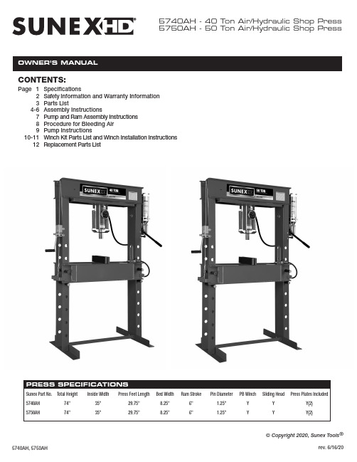
5740AH - 40 Ton Air/Hydraulic Shop Press 5750AH - 50 Ton Air/Hydraulic Shop PressCONTENTS:Page 1Specifications2Safety Information and Warranty Information 3Parts List4-6Assembly Instructions789Pump and Ram Assembly Instructions Procedure for Bleeding Air Pump Instructions10-11Winch Kit Parts List and Winch Installation Instructions 12Replacement Parts List© Copyright 2020, Sunex Tools ®SAFETY INFORMATIONThis symbol alerts you to the possibility of serious injury or death if instructions are not followed.This symbol alerts you to the possibility of damage to or destruction of equipment if instructions are not followed.Failure to heed these warnings may result in lossof load, damage to the press and/or failure resulting in property damage, personal or fatal injury. Thisoperating manual contains important details concern-ing the safe operation of this tool. The user must read and understand these details before any use of the tool. This manual must be retained for future reference.• Read, study, understand and follow all instructions before operating this press.• Always wear safety goggles, (users and bystanders).•Parts being pressed may splinter, shatter, or be ejected from the press at a dangerous rate of speed. Because there are a variety of press applications, it is the responsibility of the press owner to provide adequate guards, eye protection and protective clothing to the press operator.• Visual inspection of the press should be made before use, checking for signs of cracked welds, bent bed pins, loose or missing bolts, leaks, or any other structural damage. Corrections must be made before using the press.•Do not go near leaks. High pressure hydraulic uid can puncture skin and cause serious injury,gangrene, or death. If injured, seek emergency medical help as immediate surgery is required to remove the uid.• Prior to use make sure the press is securely anchored to a concrete oor.•Keep hands, arms, feet, and legs out of work area. Accidental slippage can result in personal injury.• Always use an accurate force gauge to measure pressing force.• Do not exceed the rated capacity or tamper with the pressure/force settings. When attachments and adapters are used the rated capacity of the system shall be no greater than the rated capacity of the lowest rated component or combination of components that make up the system. • Avoid off-center loads. Offset loads can damage ram and may cause load to eject at a dangerous rate of speed. Do not use any spacer or extender between the press ram plunger and the item being pressed. If there is not enough ram stroke, adjust the height of the movable bolster.•Remove all loads from movable bolster before attempting to adjust bolster height. Beware of possible falling bolster.•Press only on loads supported by movable bolster and press plates included. Do not support loads on oor or press frame legs.• When using any accessories such as press plates or arbor plates, be certain they are centered on the movable bolster and in full contact with both sides of the bolster.• Before applying load, be certain all movable bolster supporting pins are fully engaged. Verify lift cables (if equipped) are slack before pressing on the bolster.• Always use a bearing shield when pressing bearings.•Use caution when positioning work to be pressed to ensure the item to be pressed cannot be ejected at a dangerous rate of speed.• Release hydraulic pressure before loosening any ttings.• Maintain proper hydraulic uid levels.• Do not make any alterations or modi cations to the press.•This product may contain one or more chemicals known to the State of California to cause cancer and birth defects or other reproductive harm. Wash hands thoroughly after handling.•Failure to heed and understand these markings may result in serious or fatal personal injury and/or property damage.OWNER/USER RESPONSIBILITYThe owner and/or user must have an understanding of the manufacturer'soperating instructions and warnings before using this press. Personnel involvedin the use and operation of equipment shall be careful, competent, trained,and quali ed in the safe operation of the equipment and its proper use whenservicing motor vehicles and their components. Warning information shouldbe emphasized and understood.If the operator is not uent in English, the manufacturer's instructions andwarnings shall be read to and discussed with the operator in the operator'snative language by the purchaser/owner, making sure that the operatorcomprehends its contents.Owner and/or user must study and maintain for future reference the manufactur-er’s instructions. Owner and/or user is responsible for keeping all warning labels and instruction manuals legible and intact. Replacement labels and literature are available from the manufacturers.INSPECTIONVisual inspection of the shop press should be made before each use of the press, checking for damaged, loose or missing parts. Each press must be inspected by a manufacturer’s repair facility immediately, if subjected to an abnormal load or shock. Any press which appears to be damaged in any way, is found to be badly worn, or operates abnormally must be removed fromservice until necessary repairs are made by a manufacturers's authorized repair facility. It is recommended that an annual inspection of the press be made by a manufacturer’s authorized repair facility and that any defective parts, decals or warning labels be replaced with manufacturer’s speci ed parts. A list of authorized repair facilities is available from the manufacturer.SAFETY INSTRUCTIONS•CHECK YOUR LOCAL, STATE AND FEDERAL REGULATIONSREGARDING THE SAFE USE OF THIS EQUIPMENT.•Your safety is top priority. Please handle equipment with care.•Fully retract unit and remove all items from the press bed frame.•Support the press bed, and remove the pins.•Raise or lower bed to desired height and reinstall press pins. Be certainpins are fully engaged in the parallel anges of the upright columns.•Position press on a at, level, hard surface, preferably concrete.Make sure all nuts and bolts are tight.•Clear the area of bystanders, especially small children, before using.•Set the press bed to the required height. The press is most effectivewhen the work piece is located 1 inch below the ram’s retracted position.The compression stroke can include the entire 5 inch working range.•The press is designed to exert a force on anything which is positionedbeneath its ram. The work piece can pop out from under the ram at a high rate of speed and injure someone.•Pressing Bearings: It is essential that you use the bearing shield whenpressing bearings on or off.LIMITED WARRANTY:SUNEX INTERNATIONAL, INC. WARRANTS TO ITS CUSTOMERS THAT THE COMPANY’S SUNEX TOOLS ® BRANDED PRODUCTS ARE FREE FROM DEFECTS IN WORKMANSHIP AND MATERIALS.Sunex International, Inc. will repair or replace its Sunex T ools ® branded products which fail to give satisfactory service due to defective workmanship or materials, based upon the terms and conditions of the following described warranty plans attributed to that speci c product. This product carries a ONE-YEAR warranty. During this warranty period, Sunex T ools ® will repair or replace at our option any part or unit which proves to be defective in material or workmanship. Other important warranty information....This warranty does not cover damage to equipment or tools arising fromalteration, abuse, misuse, damage and does not cover any repairs or replace-ment made by anyone other than Sunex Tools ® or its authorized warranty service centers. The foregoing obligation is Sunex Tools ®’ sole liability under this or any implied warranty and under no circumstances shall we be liable for any incidental or consequential damages. Note: Some states do not allow the exclusion or limitation of incidental or consequential damages, so the abovelimitation or exclusion may not apply to you. Return equipment or parts to Sunex Tools ®, transportation prepaid. Be certain to include your name and address, evidence of the purchase date, and description of the suspected defect.If you have any questions about warranty service, please write to Sunex Tools ®.This warranty gives you speci c legal rights and you may also have other rightswhich vary from state to state. Repair kits and replacement parts are available for many of Sunex Tools ® products regardless of whether or not the product is still covered by a warranty plan.SHIPPING ADDRESS: MAILING ADDRESS:Sunex Tools Sunex Tools 315 Hawkins Rd. P .O. Box 4215Travelers Rest, South Carolina 29690 Greenville, South Carolina 29608THIS OPERATING MANUAL CONTAINS IMPORTANT SAFETY INFORMATION. READ CAREFULLY AND UNDERSTAND ALL INFORMATION BEFORE OPERATING THIS TOOL. SAVE THIS MANUAL FOR FUTURE USE.WARNING: This product can expose you to chemicals including nickel, which is known to the State of California to cause cancer and birth defects or other reproductive harm.For more information go to .Press Frame - 1Press Bed - 1Press Feet - 2Z Bar - 11/2"-13 x 1-1/2" Hex Head Bolts - 101/2" Nuts - 10Air MotorPump and Ram - 1Pump Extension Handle - 11" x 3" x 14"Press Plates - 2Accessory only -Not needed for assemblyPushing Adapter - 1Accessory only -Not needed for assemblyBearing Shield - 1Accessory only -Not needed for assemblyESTIMATED ASSEMBLY TIME: 30 MINUTESACCESSORIESASSEMBL CONTINUEDPUMP AND RAM ASSEMBL Y INSTRUCTIONSPROCEDURE FOR BLEEDING AIRPUMP INSTRUCTIONSWINCH INSTALLATION INSTRUCTIONS CONTINUED。
CT Elite Mount 安装指南和维修部件说明书
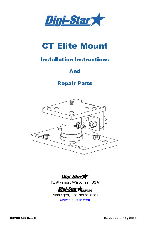
D3738-US-Rev E September 15, 2009CT Elite MountInstallation InstructionsAnd Repair PartsFt. Atkinson, Wisconsin USAPanningen, The NetherlandsTABLE OF CONTENTSINTRODUCTION .................................................................................................. TECHNICAL SPECIFICATIONSD3738-US-Rev E CT Elite Mount User’s Manual 1INTRODUCTIONThe Digi-Star CT Elite mounts are specifically designed to be used with the Digi-Star CT 10k, 30k and 50k compression load cells. The “floating design” mounts are used in stationary bin weighing applications. Checking action of the floating mount prevents side or swaying loads from interfering with the accuracy of the scales.2CT Elite Mount User’s ManualD3738-US-Rev ETECHNICAL SPECIFICATIONSMounts: Welded steel mounts with Zinc platingCapacity: 50,000 lbs (22,685 kg)Mount DimensionsD3738-US-Rev E CT Elite Mount User’s Manual3SAFETY DURING USECautionCleaningDo not use running water (high pressure cleaners, hoses) to clean the indicator.Charging Battery and WeldingDisconnect all cables from the weighing indicator before charging the battery or welding on the machine. If cables are left connected, the weighing indicator and connected load cells could be damaged.Important: Do not weld near indicator, load cells or cables, remove from area to be welded. Place ground close to area to be welded to prevent current from passing through electronic parts.4 CT Elite Mount User’s ManualD3738-US-Rev EASSEMBLE MOUNTS1. Place sealing ring (Key 11) on center ring of base plate (Key 1).2. Insert CT Load Cell (Key 10) into sealing ring.3. Mount top plate assembly (Key 2) on top of load cell, line up withcenter ring of top plate.QUESTION: What type of CT mount side plates do you have?D3738-US-Rev ECT Elite Mount User’s Manual5Option 1: Clevis Stop Pin Side PlatesFollow steps 1-3 from page 4.4. Align plate weldment (Key 3) on the outside of the mounting plate tabs.Align plate (Key 4) on the inside of tabs.5. Pass bolts (Key 7) thru welded plate (Key 3), mounts and inner plate(Key 4) as shown in figure above.6.Install nuts (Key 9) and lockwashers (Key 8). Tighten until inner plate(Key 4) is flat and tight against clevis pin stop. See Detail A-A.Important: After nuts/lockwashers are tightened, side plates (Keys 3, 4) must be loose and free and must not contact plate weldment vertical tabs otherwise weighing errors will result.7. Insert pins (Key 5) into inner holes on retaining plates8. Secure with cotter pin (Key 6), make sure it passes through pipesection on plate weldment (Key 3). Bend cotter pin to secure.Go to Page 7.6 CT Elite Mount User’s Manual D3738-US-Rev EOption 2: Bushing Stop Side PlateFollow steps 1-3 from page 4.9. Insert outer plate weldment (Key 3) through outer holes of mountingplate tabs. Align inner retaining plate (Key 4) on inside of mounting tab.10. Secure plates together by passing bolts (Key 7) through bushing stopand thread into inner plate (Key 4). Install nuts (Key 9) and lock washer (Key 8) and tighten.Note: After nut/lock washers are tightened, side plates (Key 3, 4) willremain loose around top and bottom plate tabs. This prevents weighing errors.11. Insert Pins (Key 5) into inner retaining plate holes. Secure with cotterpin (Key 6) and make sure it passed through pipe section. Bend cotter pin.Go to page 7.D3738-US-Rev ECT Elite Mount User’s Manual 7INSTALL MOUNTSFigure below shows a typical stationary bin application. Mounts can be bolted to bin leg supports first.1. Position mounts (Key 1) so they are rotated 90°as shown in figurebelow. This will restrict movement of mounts in directions up/down or left/right.2. Secure to concrete pad with 5/8-11 or 16x2.0mm concrete anchors.Four required per mount. Do not tighten hardware. Proceed to “Level Mounts” (see page 8) if required.Important: Follow the concrete anchor manufacturer’s installation instructions.Remove any dirt, rocks or foreign debris from under supports, supports must be flush with concrete pad. Holes for concrete anchors.1Flat, level, well drained concrete surface (flatness of ±1/8” is required.8CT Elite Mount User’s Manual D3738-US-Rev ELEVELING MOUNTSFor certified scale applications, there are 4 threaded weld nuts so that each mount can be leveled.1. Insert leveling bolts (user supplied) into threaded weld nuts and tightenuntil mount is level in both directions.2. When level, insert steel shims (proceed to step 4) or non-shrink grout(Step 3) between uneven surface and bottom mount to support load. The leveling bolts are not designed to support the load.3. Non-Shrink Grout Installation . Build a wooden frame around eachmount. Mix up the non-shrinkable grout. While using chemical resistant rubber gloves, push the grout in underneath the mounts. Leave the frame until grout has set-up per manufacturer’s instructions. Grout specifications: Multi-purpose non-shrink grout: Sanded,Portland-based non-shrink grout. Free of iron particles, chloride and gypsum. Must meet or exceed ASTM-C-1107 (Grade B).4. Fully tighten all concrete anchor bolts.Leveling Bolt – HHCS 5/8-11 x 1.5”, Full Thread, Gr5.1Pour grout level with top surface of bottom plate.Leveling Bolt – HHCS 5/8-11 x 1.5”, Full Thread, Gr5.5/8-11 or 16x2.0mm concrete anchor bolts. 1” x 2” wooden frame for pouring and packing non-shrink grout.D3738-US-Rev E CT Elite Mount User’s Manual 9PERIODIC MAINTENANCEEvery 6 months: Check mounts for loose nuts and bolts. Make sure that side retaining plates are free to move.10 CT Elite Mount User’s ManualD3738-US-Rev EREPAIR PARTS(P/N 405797 Pack-CT Mount Elite)(Bushing Stop Design)D3738-US-Rev E CT Elite Mount User’s Manual 11KEY QTY. PART NO.DESCRIPTIONNOTES11 404581 WELDMENT-CT MOUNT LOWER Dim “A” = .656”(Clevis Stop Design) 1 405796 WELDMENT-CT MOUNT LOWER Dim “A” = .906”(Bushing Stop Design) 2 1 404582 WELDMENT-CT MOUNT UPPER Dim “A” = .656”(Clevis Stop Design) 1 405794 WELDMENT-CT MOUNT UPPER Dim “A” = .906”(Bushing Stop Design) 3 1 404938 WELD-PLATE CT MOUNT ZP (Clevis Stop Design) 4 1 404937 PLATE-CT MOUNT ZP (Clevis Stop Design) 5 2 153024 PIN-CT MOUNT6 1 404968 PIN-COTTER 1/4 X 3.0 ZP7 2 404971 SCR-M16X2X65 HHCS ZP8 2 404969 WASH-M16 LOCK ZP 9 2 404970 NUT - M16x2 ZP 10 1 REFCELL-CT 30K TC-30' (.10%)11 1 830409 RING-SEALING 1/2" SPONGE12 1 405821 WELD-PLATE CT MOUNT (Bushing Stop Design) 131153023 PLATE-CT MOUNT THRD(Bushing Stop Design)。
CTB电子版说明书(PDF文件)-阀门电动装置使用说明书

阀门电动装置使用说明书The Guide Book Of Electr ic Actuator For Valv e目录CONTENTS产品说明及外观图Product introduction and appearance drawing-------------------------------------第3页性能参数Performance data--------------------------------------------------------------------------第7页电源及产品线路图Power and product wire drawing-------------------------------------------------------第9页安装Installation---------------------------------------------------------------------------------第10页与阀门的连接及电动蝶阀外形尺寸图Connection with valve and drawing of electric butterfly-valve-----------------第12页Appearance dimension开关型的调整Regulation of switch type product----------------------------------------------------第14页调节型的调整Regulation of adjusting type product------------------------------------------------第16页使用与维护Use and maintenance------------------------------------------------------------------第17页产品说明Product introduction电动装置设计独特、外修内刚,运转寿命超出同类产品标准的十倍。
CTB_冷阱操作说明书

地面上的身体来保护短路。
3) Temperature display lets you know current temperature.
温度显示当前温度让你知道。
4) Minimizing the size of unit to maximize the saving of space.
用纯酒精,以避免附加一些残渣蒸发器。
6) Do not wash it with an acid solution, Benzene, a sharp thing, a detergent, hot water. In case using mentioned stuff to wash it, it
不倒水的外部单位直接。
4) When you wash the body of the unit, do rinse it with water after washing it with neutral detergent.
当你洗的主体单位,用水冲洗,洗后用中性洗涤剂。
5) Use pure alcohol to avoid attaching some residua to an Evaporator.
单元的功能最大化用户和安全单位,用户的方便。有如下:
1) Adapting both refrigerant and refreezing system of LBT-type to obtain ultra low-temperature. (-40℃)
适应的制冷剂和重新冻结系统LBT-type获得超低温。(-40℃)
单位设计为220 v操作,50/60 Hz。请检查电之前堵塞。
H-300B-20-47612 HYPERVISOR VI 维修手册(中文)-15.0

版本信息
本维修手册的版本号随时可能因软件或技术规格的变更而升级,恕不另行通知。本维 修手册的版本信息如下: 版本号: 发行时间: 15.0 2015 年 04 月
© 2007-2015 深圳迈瑞生物医疗电子股份有限公司,版权所有。保留所有权利。
I
ห้องสมุดไป่ตู้ 声
明
迈瑞公司保留不事先通知而修改本维修手册内容的权利。 迈瑞公司保留不事先通知而变更技术的权利。 迈瑞公司保留不事先通知而对产品规格进行修改的权利。 迈瑞公司对于本资料不作任何形式的担保,包括(但不限于)为某种特定目的对其提 出的暗含的适销性和适合性的保证责任。 迈瑞公司仅仅在下列情况下才认为应对产品的安全性、可靠性和性能负责,即: 装配操作、扩充、重调、改进和修理均由迈瑞公司认可的人员进行; 有关的电气设备符合国家标准; 产品按照《使用说明书》进行使用。
HYPERVISOR VI 中心监护系统 Central Monitoring System
维修手册 Service Manual
知识产权
本产品及其维修手册的知识产权属于深圳迈瑞生物医疗电子股份有限公司(以下简称 迈瑞公司) ,包括但不限于专利权、商标权、著作权等。 迈瑞公司有权将本维修手册作为保密资料处理。未经迈瑞公司书面许可,任何个人或 组织不得以任何手段披露此维修手册的全部或部分信息,也不得允许他人或组织以任何手 段获取本维修手册的全部或部分信息。未经迈瑞公司书面许可,任何个人或组织不得对本 维修手册的全部或部分内容有(但不限于)发表、修改、复制、发行、出租、改编以及翻 译成其它语言之行为。
售后服务单位
名称: 地址: 邮编: 电话: 传真: 深圳迈瑞生物医疗电子股份有限公司用户服务部 深圳市南山区高新技术产业园区科技南十二路迈瑞大厦 518057 +86 755 81888998 +86 755 26582680
产品维护与故障排除简易手册
产品维护与故障排除简易手册
嗨,亲爱的朋友们!今天我来跟大家分享一份产品维护与故障排除的简易手册。
先来讲讲我自己遇到的一件事儿吧。
有一次,我朋友小李买了一台超酷的智能音箱,刚开始用的时候那叫一个美滋滋,天天放着喜欢的歌。
可没几天,这音箱突然就“哑巴”了,不出声啦!小李急得像热锅上的蚂蚁,赶紧给我打电话:“哎呀,老兄,这音箱咋没声了,快帮我瞅瞅!”
我到他家一看,先检查了一下音箱的电源,插得好好的呀。
然后我又看看是不是音量被不小心调到最低了,也不是。
这可把我俩难住了。
就在我们俩抓耳挠腮的时候,我突然想到,会不会是连接音箱的手机蓝牙出了问题?我让小李把手机蓝牙关了再开,嘿,你猜怎么着,音箱那美妙的声音又响起来啦!
小李高兴得差点跳起来,直说:“哎呀,还是你有办法!”
通过这件事,我总结了一些小经验。
首先,遇到产品出问题别慌,先从最简单的电源、连接这些地方开始检查。
然后呢,多想想平时的使用习惯,是不是不小心设置错了啥。
好啦,希望大家在遇到产品故障的时候都能冷静应对,像解决小李音箱的问题那样顺利!。
美国机器与工具公司产品维修部件手册.pdf_1719188513.1075773说明书
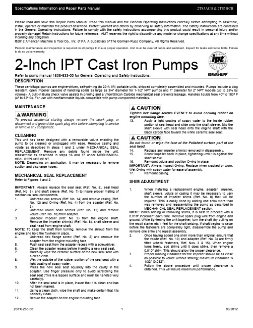
2STX-250-00103/2012Please read and save this Repair Parts Manual. Read this manual and the General Operating Instructions carefully before attempting to assemble, install, operate or maintain the product described. Protect yourself and others by observing all safety information. The Safety Instructions are contained in the General Operating Instructions. Failure to comply with the safety instructions accompanying this product could result in personal injury and/or property damage! Retain instructions for future reference . AMT reserves the right to discontinue any model or change specifications at any time without incurring any obligation.©2012 American Machine & Tool Co., Inc. of PA, A Subsidiary of The Gorman-Rupp Company, All Rights Reserved.Periodic maintenance and inspection is required on all pumps to insure proper operation. Unit must be clear of debris and sediment. Inspect for leaks and loose bolts. Failure to do so voids warranty.2-Inch IPT Cast Iron PumpsRefer to pump manual 1808-633-00 for General Operating and Safety Instructions.DESCRIPTIONThese centrifugal pumps are engine-driven, self-priming (to 20 ft. lift) portable units, shipped completely assembled and mounted. Pumps include a clog resistant, open impeller capable of handling solids as large as 3/4" diameter for 1-1/2" NPT pumps and 1" diameter for 2" NPT models (up to 25% by volume). A built-in Buna check valve assists in priming and a Viton/Silicon Carbide mechanical seal prevents leakage. Handles liquids from 40º to 180º F (4º to 82º C). For use with nonflammable liquids compatible with pump component materials.MAINTENANCETo prevent accidental starting always remove the spark plug, or disconnect and ground the spark plug wire before attempting to service or remove any component. CLEANING This unit has been designed with a removable volute enabling the pump to be cleaned or unclogged with ease. Remove casing and volute as described in steps 1 and 2 under MECHANICAL SEAL REPLACEMENT. Remove any debris found inside the unit, reassemble as described in steps 16 and 17 under MECHANICAL SEAL REPLACEMENT. NOTE: Depending on application, it may be necessary to removesuction and discharge hoses.MECHANICAL SEAL REPLACEMENTRefer to Figures 1 and 2IMPORTANT: Always replace the seal seat (Ref. No. 5), seal head (Ref. No. 6), and shaft sleeve (Ref. No. 7) to insure proper mating of mechanical seal components. 1. Unthread cap screws (Ref. No. 14) and remove casing (Ref.No. 12) and O-ring (Ref. No. 4) from the adapter (Ref. No. 3).2. Unthread round head screws (Ref. No. 15) and removevolute (Ref. No. 10) from adapter.3. Unscrew impeller (Ref. No. 9) from the engine shaft.Remove the impeller shim(s) (Ref. No. 8), shaft sleeve and seal head from engine shaft.NOTE: To keep the shaft from turning, remove the shroud from the engine and hold the flywheel in place. 4. Unthread hex flange screw (Ref. No. 2) and remove theadapter from the engine mounting face.5. Push seal seat from the adapter recess with a screwdriver.6. Clean the adapter recess before inserting a new seal seat.7. Carefully wipe the ceramic surface of the new seal seat witha clean cloth.8. Wet the outside of the rubber portion of the seal seat with alight coating of soapy water.9. Press the new seal seat squarelyinto the cavity in theadapter. Use finger pressure only to avoid scratching the seal seat (This is a lapped surface and must be handled very carefully).10. After the seal seat is in place, insure that it is clean and hasnot been marred.11. Using a clean cloth, wipe the shaft and make certain that it isperfectly clean.12. Secure the adapter on the engine mounting face.Tighten hex flange screws EVENLY to avoid cocking rabbet on engine mounting face.13. Apply a light coating of soapy water to the inside rubberportion of seal head and slide onto the shaft sleeve. Slip the shaft sleeve with seal head onto the engine shaft with the black carbon face toward the white ceramic seal seat.Do not touch or wipe the face of the Polished surface part of the seal head. 14. Replace any impeller shim(s) removed in disassembly. 15. Screw impeller back in place, tightening until it is against theshaft sleeve.16. Remount volute and position O-ring in place.IMPORTANT: Always inspect O-ring. Replace when cracked or worn. Wet O-ring with soapy water for ease of assembly. 17. Remount casing.SHIM ADJUSTMENT1.When installing a replacement engine, adapter, impeller, shaft sleeve, volute or casing it may be necessary to vary the number of impeller shims (Ref. No. 8) that will be required. This is easily done by adding one shim more than was removed and reassembling the pump as described in MECHANICAL SEAL REPLACEMENT section.NOTE: When adding or removing shims, it is best to proceed with a 0.010" increment each time. Remove spark plug wire from engine and ground. While tightening the unit together, turn the shaft (by pulling on the recoil starter etc.); feel for the shaft seizing. If shaft begins to seize before the fasteners are completely tight, disassemble the pump and remove one shim and repeat assembly. 2. Once having added one shim more than original, ensure thatthe volute (Ref. No. 10) and adapter (Ref. No. 3) are firmly fitted (check fasteners, Ref. Nos. 2 & 15). When engine turns freely,add shims until it does strike, then remove a 0.010" shim. This should allow the proper clearance.3. Proper running clearance for the impeller should be as closeas possible to volute without striking; maximum clearance is 1/32" (0.032").4. Follow the above procedure until proper clearance isobtained. This will insure maximum performance.2STX-250-00203/20122-Inch IPT Cast Iron PumpsRepair Parts ListPart Number for Models:Ref. 2TS5ACBNo. Description 2TS5HCB Qty.1 Engine B&S (2TS5ACB) 1639-034-00 1Engine Honda GX160 (2TS5HCB) 1639-036-00 12 Hex Head Cap Screw * 43 Adapter 2182-010-01 14 O-Ring 2186-000-00 14 O-Ring - Viton (optional) 2186-001-00 15 &6 ⑤Shaft Seal Assembly - Silicon Carbide/Viton 1641-166-91 17 Shaft Sleeve 1483-140-09 18 Impeller Shim Package 1658-000-90 19 Impeller 3935-012-01 110 Volute 2182-002-01 111 Flapper Valve 1609-002-00 111 Flapper Valve - Viton (optional) 1695-011-90 112 Casing 2112-001-02 113 1/2" NPT Plug * 214 Hex Head Cap Screw * 415 Socket Head Screw SS 1705-000-00 216 Nut * 417 Hex Head Cap Screw * 418 Hex Nut * 419 Flat Washer * 420 Lock Washer SS 1787-000-00 221 Roll Cage Frame Assembly 3120-105-K0 1❒ Raising Block 3120-119-90 2❒ NPT Pipe Nipple Kit C366-90 1❒ NPT Suction Strainer C362-90 1❒ 2” NPT Street Elbow1695-070-00 1❒ Wheel Kit (optional) A374-90 1(*) Standard Hardware Item, Available Locally(⑤) Seal assembly available as set only (includes seal head and seat).(❒) Not Shown2STX-250-00 3 03/2012。
最新最新国内外医疗器械实用维修手册
第一篇总论第一篇总论第一章概述一、总论检验医学在国外习惯上称为实验室医学(Laboratory Medicine)。
它是一门涉及范围相当广泛,包括多个专业的交叉性学科。
随着现代医学的不断发展,临床检验的范围日益广泛,检验的项目也越来越多。
各种定量的检测结果对疾病的诊断、治疗、预后判断和健康评价有着十分重要的价值,正在发挥着越来越大的作用。
近年来,由于临床诊断、治疗、预后监测和医学研究的诸多需要,医学检验方法的进展十分迅速,血液学、免疫学、生物化学和微生物学的任何新理论,新技术以及重大科研成果,凡是能直接用于诊断疾病的,或早或迟都会发展成为一种检验方法,进入临床实验室。
相应的检验仪器更是日新月异。
随着数学方法和统计学方法、电子技术和计算机技术向检验医学的广泛渗透,使得临床检验仪器都向着机械化、自动化、精密化和简易化的方向发展,大大地提高了临床检验的速度与精度以及对资料的处理能力和管理质量。
随着高灵敏度、多功能、智能化程度较高的检测仪器的不断涌现和广泛应用,临床医学的发展对实验室检验,判断结果的依托性的不断增大,对检验工作者的专门知识和技术技能要求越来越高。
培养和提高医学院校相关专业的各层次学生及实验室工作人员熟练掌握和使用各类现代化检验仪器,使之在辅助诊断和治疗中发挥最佳的效能,成为相当急迫、重要的事情。
教育培养各层次学生和相关工作人员掌握各种常用检验仪器的工作原理、分类结构、性能指标、使用方法、常见故障的排除、临床检验仪器中的计算机技术,并了解其发展趋势,为他们更好地从事临床检验工作打下坚实的基础。
二、临床检验仪器的分类和进展(一)临床检验仪器的分类临床检验仪器的分类历来就是一个比较困难的问题,各方面人士对此争议较大。
有主张以临床检验的方法为主对临床检验仪器进行分类的,如按目视检查、理学检查、化学检查、显微镜检查、自动化仪器检查等进行分类;也主张以检验仪器的工作原理为主对临床检验仪器进行分类的,如按力学式检验、电化学式检验、光谱分析检验、波谱分析检验等进行分类。
CTB概要设计说明书
国科电流互感器二次开路保护器软件v1.0设计说明一引言1、目的:让读者了解如何使用MPLAB8.56、PICC编译器、MPLAB C30如何使用用C语言在此软件中编写程序,查看相关资料,并且编号程序后如何检查语法错误和配合该软件的单片机相关资料的语法错误,编号程序后,如何仿真程序检查所写软件符合想要的功能,并将程序烧写进单片机。
2、项目背景:(1)项目委托单位:开发单位:安徽国科电力保护设备有限公司主管部门:研发部(2)该软件系统和其他系统之间的关系:该软件在是在windows xp以上的系统软件下运行3、定义专业用语和缩写:I/O是指对应单片机的每个管脚、仿真烧写器是指将编译好的程序下载到单片机运行,可以让单片机受软件控制运行,也可以烧写进单片机让其离开PC机后单独运行。
4、参考资料:《PIC单片机C语言程序设计实例精粹》刘向宇、秦龙编;《Microchip PIC24系列单片机原理与设计程序》何此昂;《PIC技术宝典》李中华著。
二、任务概述1、目标如何使用该软件,简介在该环境下如何设置PICC,运用C语言编程和一些与常见C语言编写的不同之处,和一些简单等调试步骤2、运行环境Windows XP以上操作系统、512M以上内存、一般集成显卡即可、20G以上硬盘3、需求概述在具备以上软件等基础之上,还需要仿真烧写器,该模块如ICD2、PICKIT2或者是PICKIT3,他们是用来仿真程序找出错误、如果程序正确无误即可将其烧写进去这样可以离开PC机可单独运行4、条件与限制具有良好的C语言基础、并且有良好等英语阅读能力,能看东常见等单片机英文资料三、总体设计1、处理流程:(1)、安装好MPLAB软件、PICC编译器、MPLAB C30 (2)、新建工程(3)、新建文件(4)、编写程序(5)、找出相关语法错误(6)、下载仿真查看相关现象是否和软件编写等效果一样(7)、修改相关程序(8)、将程序烧写入单片机2、总体结构和模块外部设计:在设计这些软件程序之前要处理好相关PIC单片机的外围电路,包括仿真调试用单片机引出的4个常见IO口等。
产品维护与修理手册
产品维护与修理手册
嘿,朋友们!今天我要跟你们唠唠产品维护与修理这档子事儿。
就拿我家那台老是出毛病的空调来说吧。
这空调啊,一到夏天就跟个调皮的孩子似的,时不时闹点情绪。
有一回,大夏天的,外面热得像蒸笼,我下班回到家,满心欢喜地想开空调凉快凉快。
结果,它呼呼地吹了半天,愣是一点凉气都没有。
我这心里那个急呀!赶紧给维修师傅打电话。
维修师傅倒是来得挺快,进门就问:“咋回事儿呀?”我苦着脸说:“师傅,这空调不制冷啦,热死我了!”师傅二话不说,开始检查起来。
他这儿瞅瞅,那儿摸摸,然后皱着眉头说:“这外机太脏啦,散热不好,能制冷才怪!”我在旁边一脸懵:“啊?这也能影响?”师傅笑着说:“那可不,就像人热了得出汗散热,它这外机散热不好,能工作好吗?”
说着,师傅就开始动手清理外机,那认真劲儿,就跟给自己家干活似的。
我在旁边递工具,一边跟师傅闲聊。
师傅还教我:“平时啊,你也得注意点,别让外机周围堆满杂物,影响它呼吸。
”
经过师傅一番捣鼓,嘿,这空调又欢快地吹出凉气啦!
所以说呀,朋友们,产品维护真的很重要。
咱得像照顾孩子一样,多留意它们的情况,发现问题及时处理,这样它们才能好好为咱们服务。
好啦,今天就跟大家分享到这儿,希望大家的产品都能乖乖听话,不出毛病!。
Pro Series Service Cart CTBMM100BR 产品说明书
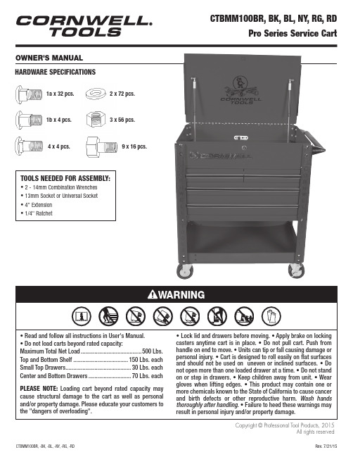
OWNER'S MANUALCopyright © Professional Tool Products, 2015All rights reserved HARDWARE SPECIFICATIONSTOOLS NEEDED FOR ASSEmbLy:• 2 - 14mm Combination Wrenches• 13mm Socket or Universal Socket• 4" Extension• 1/4" Ratchet1a x 32 pcs.1b x 4 pcs.2 x 72 pcs.3 x 56 pcs.4 x 4 pcs.9 x 16 pcs.Due to the weight of this cart we recommend that two people worktogether on the assembly. This cart weighs approximately 170 lbs, please use caution during assembly. Step 1:Locate the key tied to the bottom tray. Using the key, open the lid and remove the caster box from the bottom drawer. Once removed make sure all drawers are completely closed and the inside lever is in the locked position. Close the top lid and lock.Step 2: Lay out a work surface using the protective foam provided. Once this surface is secure gently turn the cart onto its lid. (logo will be facing the foam)Step 3:(Before assembling the legs, remove the cable tie holding the bumper in place) Insert the front leg (#7), labeled FL or FR into top lip of the cart. Then place the Front bumper (#14 with Cornwell Logo) over the leg aligning the center bolt holes. With holes aligned insert stove bolt (#1a) and finger tighten with nyloc nut and washerStep 4:Install back leg (#7) labeled BL or BR and bumper (#14 without logo) following the same procedure as above. Note: Make sure the back leg is inside the hinge rivet. Otherwise the holes will not line up during assemblyASSEMBly INSTRUCTIONSStep 8:Insert bottom shelf (#23) between the four legs flat side facing up towards the ceiling. Insert sixteen stove bolts (#1a) and completely tighten.Step 5: Repeat steps 3 & 4 to mount the legs on the opposite side. Step 6: Completely tighten the 8 bolts just inserted.Step 7:Insert bottom shelf (#23) between the four legs flat side facing up towards the ceiling. Insert sixteen stove bolts (#1a) and completely tighten.Troubleshooting Points during CTBMM100 Assembly.Problem: Drawers appear not to fit, do not slide in accurately and bump the cart sides.Solution: The roller bearing slides must be fully engaged into the mounting slots on all drawers. They potentially could fall out of position while turning the cart on its lid, back, or onto its casters.Remove the drawer that is out of position. The drawer is removed by the two clips on the roller bearing slides.Simply push the roller bearing slide back down into position. Insert the drawer back onto the roller bearing slides.Problem: Back Lock/Unlock Switch does not engage the drawer.Solution: The inside Lock/Unlock slide potentially could fall out of its groove while turning the cart on its lid, back, or onto its casters during assembly.Unscrew the four screws that are holding the Lock/Unlock slide in place. Once the screws are removed simply place the latch back onto the slide and tighten the four screws back down.Problem: Back Lock/Unlock Switch does not engage the drawer.Solution: The inside Lock/Unlock slide potentially could fall out of its groove while turning the cart on its lid or back onto its casters.Unscrew the four screws that are holding the Lock/Unlock slide in place.Once the screws are removed simply place the latch back onto the slide and tighten the four screws back down.Step 13: Insert the remaining 8 stove bolts (#1a).Step 14: Using 13mm socket completely tighten all fasteners!!Step 15: Insert spray can holder divider (#19) into provided cutaway on the bottom shelf (#23). (Optional)ASSEMBly INSTRUCTIONSStep 8:Mounting casters: Put the four casters in place. The two lockingcasters (#12) should be on one side of the cart and the two non locking casters (#10) should be on the other (left or right side Not front or back). Using the 16 bolts (#9), washers and fasteners (located in separate Caster bag) completely tighten the casters to the bottom tray using a 13mm socket and 14mm combination wrench for the bolt head. (Note: Bolt head and one washer should be on the inside of the bottom shelf, nyloc nut Step 10: Open top lid using the key providedStep 11: Mount push handle (#6) to the same side of the cart withthe locking casters using the four stove bolts (#1b) provided. Finger tighten at this time.Step 12: Insert the 4 Stove bolts (#4) provided to the opposite side of thecart. Note: This stove bolt is shorter due to not having to pass through a handle or bumper.TROUBlESHOOTINGI tem # part # Description QtY. 1a *M8x22 Bolt 32 1b *M8x28 Bolt 42 *M8 Washer 723 *M8 Locking Nut 564 *M8x22 Bolt 45 RSMM100HB Handle Brackets/Pair 16 RSMM100HDL Handle 17 RSMM100LG-BR (burgundy) Leg/each 4RSMM100LG-BK (black)RSMM100LG-BL (blue)RSMM100LG-NY (yellow)RSMM100LG-RG (orange)RSMM100LG-RD (red)8 RSMM100SRP-BR (burgundy) Screwdriver/Prybar Holder/each 2RSMM100SRP-BK (black)RSMM100SRP-BL (blue)RSMM100SRP-NY (yellow)RSMM100SRP-RG (orange)RSMM100SRP-RD (red)9 *M8x19 Bolt (for casters) 1610 RSSWCS 5" Swivel Caster (non-locking)/each 211 RSMM100RP-BR (burgundy) Reinforced Piece /each 2RSMM100RP-BK (black)RSMM100RP-BL (blue)RSMM100RP-NY (yellow)RSMM100RP-RG (orange)RSMM100RP-RD (red)12 RSSWLCS 5" Swivel Caster with lock/each 2 13a RSMM100DH Drawer Handle/each 2 13b RSMM100SDH Short Drawer Handle/each 214 RSMM100BP Set of 4 Bumpers 115 *Screw for Drawer Handles 1216 RSLKN Lock with Keys17 RSGP Gas Piston /eachRSRBS Roller Bearing Slides/pair19 RSMM100SCD-BR (burgundy) Spray Can Divider 1RSMM100SCD-BK (black)RSMM100SCD-BL (blue)RSMM100SCD-Y (yellow)RSMM100SCD-RG (orange)RSMM100SCD-RD (red)20 CTB100MMLDBRL (burgundy) 3-1/4" Half Drawer Left 1CTB100MMLDBKL (black)CTB100MMLDBLL (blue)CTB100MMLDNYL (yellow)CTB100MMLDRGL (orange)CTB100MMLDRDL (red)20a CTB100MMLDBRR (burgundy) 3-1/4" Half Drawer Right 1 CTB100MMLDBKR (black)CTB100MMLDBLR (blue)CTB100MMLDNYR (yellow)CTB100MMLDRGR (orange)CTB100MMLDRDR (red)21 CTB100MMLD2BR (burgundy) 3-1/4" Drawer 1CTB100MMLD2BK (black)CTB100MMLD2BL (blue)CTB100MMLD2NY (yellow)CTB100MMLD2RG (orange)CTB100MMLD2RD (red)22 CTB100MMLD3BR (burgundy) 5-1/4" Drawer 1CTB100MMLD3BK (black)CTB100MMLD3BL (blue)CTB100MMLD3NY (yellow)CTB100MMLD3RG (orange)CTB100MMLD3RD (red)I tem # part # Description QtY.23 CTB100MMSBR (burgundy) Bottom Shelf 1CTB100MMSBK (black)CTB100MMSBL (blue)CTB100MMSNY (yellow)CTB100MMSRG (orange)CTB100MMSRD (red)PART DRAWINGS5push HandleBracket6push Handle 7legs (4)8pry BarHolder (2)14Bumper (4)2 with logo, 2 without10Non-lockingCaster (2)11Front & BackBracket12locking SwivelCaster (2)Narrow SideSmall lip13bShort DrawerHandle (2)13aDrawerHandle (2)19paint CanHolder Divider2321a1413a13b101912987651b34Front Right Bumper 21222020a11PARTS lIST* Available in RSMM100BK Bolt Kit.Also available: RSSCPK Service Cart Polishing Kit, RSDET8PK Ball Bearing Slide Detents (Pk of 8)。
- 1、下载文档前请自行甄别文档内容的完整性,平台不提供额外的编辑、内容补充、找答案等附加服务。
- 2、"仅部分预览"的文档,不可在线预览部分如存在完整性等问题,可反馈申请退款(可完整预览的文档不适用该条件!)。
- 3、如文档侵犯您的权益,请联系客服反馈,我们会尽快为您处理(人工客服工作时间:9:00-18:30)。
主轴电机光电编码器拆卸和安装方法一.拆卸和安装所需工具和零件。
十字螺丝刀1把,M5、M4、M3、M2六方扳手各1把,M5X35六方螺钉1 件。
二.拆卸方法和步骤1.拆下主轴电机后端的电机风扇罩和编码器密封盖。
2.拆开电机接线盒,拆下编码器接口板,拔下与编码器连接的电缆。
3.用M2的扳手拆下光电编码器两边的M3X8螺钉,注意保存螺钉的平垫和弹簧垫。
4.用M3扳手拆下编码器中间M4X30的螺钉。
5.用M5X35的螺钉从后端旋进编码器的空心轴,直至将编码器顶出,拆卸工作完成。
三.安装方法和步骤1.将新的编码器对准电机尾部的锥轴,轻轻压下。
2.用M3扳手将M4X30的螺钉,拧进编码器空心轴并且拧紧,以保证主轴电机运转时编码器轴与电机轴同步旋转。
3.用M2扳手将M3X8的螺钉固定码盘两侧弹性安装片,注意加装弹簧垫和平垫,防止松动。
4.插上与编码器连接的电缆,固定好接口电路板。
5.用M3扳手将密封盖安装好,注意重新装好密封圈。
6.用M5扳手将电机风扇罩和接线盒装好,码盘安装过程完成。
7.在主轴驱动器上重新调整主轴准停位置。
调试主轴电机磁码盘的方法(使用MENC3型接口板)1.将控制器断电,先拆开电机的接线盒,再将编码器接线盒的四个螺钉打开,此时能看到编码器电路板。
(如左下脚图所示)2.将电机后端风机罩取下,再用六角扳手将磁码盘密封盖取下,此时能看到码盘和编码器的磁检测头。
3.用0.15mm或0.20mm的塞尺放在检测头与磁盘之间,使塞尺尽量与检测头和码盘紧密接触,并保持平行。
4.插好编码器电缆,给驱动器上电,但不要让电机运转。
5.A相的调整:将万用表调到直流2V电压档,将红、黑表笔分别接到A+和A—上,调节对应A相的电位器P1,直至使A+和A—之间的电压为0V即可。
6.B相的调整:将万用表调到直流2V电压档,将红、黑表笔分别接到B+和B—,调节对应B相的电位器P2,直至使B+和B—之间的电压为0V即可。
7.Z相的调整:将万用表调到直流2V电压档,将红、黑表笔分别接到Z+和Z—,调节对应Z相的电位器P3,直至使Z+和Z—之间的电压为—0.4V左右即可。
8.调整完毕后,用气将编码器室清理干净,保证没有铁屑吸附在检测头上。
9.装好密封盖、风机和接线盒。
A、B、Z三相测试点请看下图编码器接口板MENC3主轴电机编码器线号定义及示图12345678910针针针针针针针针针针针灰针针针针针针针针接线表:接线表:主轴驱动器模块测量方法一、 整流模块检测1.整流模块上桥臂检测方法(1)将欧姆表,打到“二极管”测量档。
(2)负表笔接在P1端子上,正表笔依次连接端子R 、S、T,三次的测量值都应在400~600之间。
(3)互换表笔,重复上一步操作,若测量值都为无穷大,则整流模块上桥臂正常。
2.整流模块下桥臂检测方法(1)将欧姆表,打到“二极管”测量档。
(2)正表笔接在N端子上,负表笔依次连接端子R 、S、T三次的测量值都在400~600之间。
(3)互换表笔,重复上一步操作,若测量值都为无穷大,则整流模块上桥臂正常。
二、逆变模块检测1.逆变模块上桥臂检测方法(1)将欧姆表,打到“二极管”测量档。
(2)负表笔接在P1端子上,正表笔依次连接端子U 、V、W,三次的测量值都应在400~600之间。
(3)互换表笔,若测量值都为无穷大,则逆变模块上桥臂正常。
2.逆变模块下桥臂检测方法(1)将欧姆表,打到“二极管”测量档。
(2)正表笔接在N端子上,负表笔依次连接端子U 、V、W,三次的测量值都应在400~600之间。
(3)互换表笔,若测量值都为无穷大,则逆变模块上桥臂正常。
三、制动单元的检测(1)将欧姆表,打到“二极管”测量档。
(2)将正表笔接在PB端子上,负表笔接在P端子上,测量值在400~600之间;再将负表笔接在N端子上,测量值为无穷大。
(3)将负表笔接在PB端子上,正表笔接在P端子上,测量值为无穷大;再将负表笔接在N 端子上,测量值在400~600之间;则制动单元正常。
驱动器部模块原理图:VU10Ω/15W (2个)逆变部分制动单元整流部分TS R主轴驱动器操作面板操作及状态监视方法(使用060720型操作面板)操作面板是超同步驱动器的标准配置。
用户可以通过操作面板对驱动器进行参数设定、状态监视、运行控制、参数复制等操作。
熟悉操作面板的功能与使用,是使用超同步驱动器的前提,合理运用和操作能对驱动器出现的一些故障现象和状态,做出明确科学的判断,对解决问题起到事半功倍的作用。
一.驱动器操作面板的操作。
驱动器的操作面板采用三级菜单结构,可以方便快捷地查询、修改各菜单项的参数值。
三级菜单分别为:菜单项(一级菜单)、参数项(二级菜单)、参数设定值(三级菜单)。
操作流程如图1-1所示。
二.参数复制功能驱动器的操作面板具有参数复制、存储功能,该功能可以复制、保存驱动器的设定参数(Sn 和Cn菜单中的所有参数),并具有掉电保护功能。
参数复制分为参数上传、参数下载两种。
参数上传:指将驱动器控制板中的参数上传到操作面板的EEPROM中进行保存。
图1-2为参数上传的操作流程示意图。
参数下载:指将操作面板中存储的参数下载到驱动器的控制板中,使二者中的参数保持一致。
图1-3为参数下载的操作流程示意图。
★说明:⑴由于每次驱动器上电,操作面板首先进行大约5秒钟的初始化过程,在上电初始化完毕后,都要将操作面板中存储的参数下载到驱动器的控制板中进行保存,所以不同系列的驱动器之间禁止使用。
图1-2 参数上传操作流程示意图图1-3 参数下载操作流程示意图⑵每次上电操作面板向驱动器控制板下载参数时,操作面板首先要检测驱动器是否处于停机状态,如果是则向驱动器控制板下载参数,否则跳过这一步,进入下一环节。
⑶在操作面板参数上传、下载的过程中,为了保证参数的完整性和一致性,操作面板封锁任何按键操作,不能中途退出。
⑷在操作面板的EEPROM中分为两块区域,一块为原始数据区,另一块为当前数据区。
原始数据区中存储的数据是出厂时Sn、Cn菜单中的参数值;当前数据区中存储的数据是当前Sn、Cn菜单中的参数值。
每次用户在操作面板上设置完参数后,新的参数值首先保存到驱动器控制板中,然后再保存到操作面板的当前数据区相应的EEPROM中。
每次驱动器上电,操作面板都是将当前数据区中存储的数据下载到驱动器的控制板中。
⑸操作面板的参数上传、下载操作,只能在驱动器处于停机状态时才能进行。
参数上传、下载操作只需在下列情况下使用:在使用过程中如果用户想把当前Sn、Cn菜单中的参数保存起来,以备以后恢复,但又不能影响当前的参数值,则可使用参数上传功能,这样就可把参数保存到操作面板的原始数据区中。
在使用过程中如果用户想把出厂值或以前保存的Sn、Cn菜单中的参数恢复成当前值,则可使用参数下载功能,这样操作面板当前数据区中的数据和驱动器控制板中的数据就被刷新成原始数据区中的数据了。
图1-1 操作面板操作流程示意图控制器SCP04主板更换为CP06A主板梯形图改变说明:因我公司产品改进SCP04主板已停止生产。
当用户使用的SCP04主板出现故障时,我公司一般都为用户提供CP06A 主板予以替代。
当用户使用的是汉川机床FANUC 数控时,当主轴控制器的主板由SCP04换为CP06A 时,其数控系统梯形图请参见下文予以修改。
文中带*号处为要修改。
M19 ON*******主轴驱动器主板更换说明说明:由于超同步公司发展迅猛,公司产品更新较快,现许多老产品型号主轴控制器主板已停止生产。
考虑到原老型号主板在市场中还占一定的用户比例,现将老主板更换为新型号主板CP06A时的方法和注意事项做以说明。
i.BK02.2主板更换为CP06A主板1.BK02.2主板视图2.02.2主板更换为CP06A主板的端子对照接线图。
A+CP06A 接口板端子图A +COMM00S V I 1I 2S C I 1I 2Q1O7I 5DA0X3X2AD0DA1GND X1X0AD1I 7I 6I 0I 7I 7I 5I 3I 4I 6I 3I 4I 6I 5S C S V S C Q 3Q 2Q 4Q5Q 1I 5I 4Q 0I 2I 3I 1Q 2Q 3I 7I 6Q0BK-02.2接口板端子图O6O5O4O3MB M10M11O2MC M01MA M A E M11M A M 00M 01Q2Q3MA M00M 11M 10MC MB M01M10M B M C 5V G G M B M C PV2PV1G P V 1G OA+A+OA-A-GN D Z+EB +A -B -Z+B +A -OB+B+OB-B-B -OZ-Z-Z+Z-E 5V Z-PV2E A -A +B +B -O A -O A +G O B +O B -Z+Z-OZ+O Z-E FV 对应-10V —+10V FC AD1FV/FI GNDFI 对应 0V —+10VI 0I 0COM I 0I 1I 2I 3I 4G A+A-B+B-Z+Z-5V G A+A-B+B-Z+Z-5VPG1PG2M01M00M10M11OZ+ii. SCP04主板更换为CP06A 主板1. SCP04主板示图2. SCP04主板更换为CP06A 主板的端子对照接线图。
A+CP06A 接口板端子图A +A-SB-S V I 1I 2S C I 1I 2Q1I 5I 0SC I 6I 2I 4SC I 7Q 0I 0I 7I 7I 5I 3I 4I 6I 3I 4I 6I 5S C S V S C Q 1Q0Q 2Q 3Q 1I 5I 4Q 0I 2I 3I 1Q 2Q 3I 7I 6Q0SCP04接口板端子图E FV MB SA-SA+GND MC SB+MA M A E M11M A M 00M 01Q2Q3MA M00M 11M 10MC MB M01M10M B MC 5V G G M B M C PV2PV1G P V 1G OA+A+OA-A-GND Z+EB +A -B -Z+B +A -OB+B+OB-B-B -OZ-Z-Z+Z-E 5V Z-PV2E SA-SA+SB+SB-O A -O A +G O B +O B -SZ+SZ-OZ+O Z-E FV 对应-10V —+10V FC FV FV/FI FI 对应 0V —+10VI 0I 0SC A D 1I 1C O M I 3Q 2OZ++24V OVGNDQ 1Q 3A D05V GND A+B-B+Z-Z+GND SZ-SZ+T+R+T-R-注意:在更换中如有其它疑问,可参见CP06A 说明书,也可直接咨询我公司。
CP06A 主板跳线说明1. JP1设置 选择PNP/NPN JP1的设置2.JP2设置直流+24V 选择:部/外部 JP2的设置3.JP4设置QMCL程序选择跳线JP4的设置3.J1/J2设置用于设置模拟量输入端口FI:FI的设置4.模拟量端口定义模拟量输入主轴驱动器参数表系统参数用户参数主轴驱动器常见故障及处理(过流故障)电机运行加速段功率模块过流故障(主要是过流,也可能过热、驱动电源欠压等)。