LED恒温加热平台说明书(英文版)
恒温控制器操作指南说明书
Step 11. Enter to the Thermocouple Type Input Submenu Press d to display flashing, previously selected Thermocouple type.Step 12. Scroll through available selection of TC types Press b to sequence thru flashing Thermocouple types,(select k -for type "K" CHROMEGA TM /ALOMEGA TM )J K T E N DIN J R S B C - TC types J k t E N dN J R S b C - DisplayStep 13. Store TC typeAfter you have selected the Thermocouple type press d to store your selection, the instrument automatically advances to the next menu item.Step 14. Enter to Reading Configuration MenuThe display shows RDG Reading Configuration, which is the top menu for 4 submenus: Decimal Point, Degree Units, Filter Constant and Input/Reading Submenus.Step 15. Enter to Decimal Point Submenu Press dto show DEC Decimal Point.Step 16. Display the Decimal Point positionPress d again to display the flashing Decimal Point position.Step 17. Select the Decimal Point position Press b to select FFF.F Decimal Point position.Step 18. Store selected Decimal Point positionBy pressing d momentarily the Decimal Point position will be stored and the instrument will go to the next menu item.Step 19. Enter to Temperature Unit Submenu Display shows TEMP Temperature Unit.Step 20. Display available Temperature Units Press d to display the flashing Degree °F or °C .Step 21. Scroll through Temperature Units selection Press b to select °F Degree.Step 22. Store the Temperature UnitPress d to display momentarily that the Degree Unit has been stored and the instrument will go automatically to the next menu item.Step 23. Enter the Filter Constant Submenu Display shows FLTR Filter Constant Submenu.Step 24. Display the Filter Constant Value Submenu Press d to display the flashing, previously selected Filter Constant.Step 25. Scroll through available Filter Constants Press b to sequence thru Filter Constants 0001, 0002,0004, 0008, 0016, 0032, 0064and 0128.Step 26. Store the Filter ConstantPress d momentarily to store 0004Filter Constant and the instrument will automatically go to the next menu item.Step 27. Enter Alarm 1 MenuPress a until the ALR1Alarm 1 Menu appears on the Display. In the following steps we are going to DisableLatch, Active Above, Deadband 020.0, and above Setpoint 1Value will activate Alarm 1.Step 28. Select Latch Type SubmenuPress d to display flashing DSBL / ENBL .If flashing DSBL is displayed, press a , if ENBL is displayed, press b until DSBL is displayed, then press d to store and go to the next menu item.Step 29. Select the Above Type of Active Submenu Press d . If flashing ABoV Above is displayed, press a ,otherwise press b until ABoV is displayed. Press d to store and advance to next menu item.WARRANTY/DISCLAIMEROMEGA ENGINEERING, INC. warrants this unit to be free of defects in materials and workmanship for a period of 61 months from date of purchase. OMEGA’s WARRANTY adds an additional one (1) month grace period to the normal five (5) year product warranty to cover handling and shipping time. T his ensures that OMEGA’s customers receive maximum coverage on each product.If the unit malfunctions, it must be returned to the factory for evalua-tion. OMEGA’s Customer Service Department will issue an Authorized Return (AR) number immediately upon phone or written request. Upon examination by OMEGA, if the unit is found to be defective, it will be repaired or replaced at no charge. OMEGA’s WARRANTY does not apply to defects resulting from any action of the purchaser, includ-ing but not limited to mishandling, improper interfacing, operation outside of design limits, improper repair, or unauthorized modifica-tion. This WARRANTY is VOID if the unit shows evidence of having been tampered with or shows evidence of having been damaged as a result of excessive corrosion; or current, heat, moisture or vibration; improper specification; misapplication; misuse or other operating conditions outside of OMEGA’s control. Components in which wear is not warranted, include but are not limited to contact points, fuses, and triacs.OMEGA is pleased to offer suggestions on the use of its vari-ous products. However, OMEGA neither assumes responsibil-ity for any omissions or errors nor assumes liability for any damages that result from the use if its products in accordance with information provided by OMEGA, either verbal or writ-ten. OMEGA warrants only that the parts manufactured by the company will be as specified and free of defects. OMEGA MAKES NO OTHER WARRANTIES OR REPRESENTATIONS OF ANY KIND WHATSOEVER, EXPRESSED OR IMPLIED, EXCEPT THAT OF TITLE, AND ALL IMPLIED WARRANTIES INCLUDING ANY W ARRANTY OF MERCHANTABILITY AND FITNESS FOR A PARTICULAR PURPOSE ARE HEREBY DISCLAIMED. LIMITATION OF LIABILITY: The remedies of purchaser set forth herein are exclusive, and the total liability of OMEGA with respect to this order, whether based on contract, warran-ty, negligence, indemnification, strict liability or otherwise, shall not exceed the purchase price of the component upon which liability is based. In no event shall OMEGA be liable for consequential, incidental or special damages.CONDITIONS: Equipment sold by OMEGA is not intended to be used, nor shall it be used: (1) as a “Basic Component” under 10 CFR 21 (NRC), used in or with any nuclear installation or activity; or (2) in medical appli-cations or used on humans. Should any Product(s) be used in or with any nuclear installation or activity, medical application, used on humans, or misused in any way, OMEGA assumes no responsibility as set forth in our basic WARRANT Y/DISCLAIMER language, and, additionally, purchaser will indemnify OMEGA and hold OMEGA harmless from any liability or damage whatsoever arising out of the use of the Product(s) in such a manner.RETURN REQUESTS/INQUIRIESDirect all warranty and repair requests/inquiries to the OMEGA Customer Service Department. BEFORE RE URNING ANY PRODUC (S) O OMEGA, PURCHASER MUS OB AIN AN AUTHORIZED RETURN (AR) NUMBER FROM OMEGA’S CUSTOMER SERVICE DEPART MENT (IN ORDER T O AVOID PROCESSING DELAYS). T he assigned AR number should then be marked on the outside of the return package and on any correspondence.FOR WARRANTY RETURNS, please have the followinginformation available BEFORE contacting OMEGA:1. Purchase Order number under which the product was PURCHASED,2.3. Model and serial number of the product under warranty, and Repair instructions and/or specific problems relative to the product.FOR NON-WARRANTY REPAIRS, consult OMEGA for current repair charges. Have the following information available BEFORE contacting OMEGA:1. P urchase Order number to cover the COST of the repair or calibration,2.3.Model and serial number of the product, and R epair instructions and/or specific problems relative to the product.OMEGA’s policy is to make running changes, not model changes, whenever an improvement is possible. This affords our customers the latest in technology and engineering.OMEGA is a trademark of OMEGA ENGINEERING, INC.© Copyright 2018 OMEGA ENGINEERING, INC. All rights reserved. T his document may not be copied, photocopied, reproduced, translated, or reduced to any electronic medium or machine-readable form, in whole or in part, without the prior written consent of OMEGA ENGINEERING, INC.MQS 3720/0818This Quick Start Reference provides information onsetting up your instrument for basic operation. Thelatest complete Communication and OperationalManual as well as free Software and ActiveXControls are available at or onthe CD-ROM enclosed with your shipment.The instrument is a panel mount device protected in accordance with EN 61010-1:2001, electrical safety requirements for electrical equipment for measurement, control and laboratory.Remember that the unit has no power-on switch. Building installation should include a switch or circuit-breaker that must be compliant to IEC 947-1 and 947-3. SAFETY:•Do not exceed voltage rating on the label located onthe back of the instrument housing.•Always disconnect power before changing signal andpower connections.•Do not use this instrument on a work bench withoutits case for safety reasons.•Do not operate this instrument in flammable orexplosive atmospheres.EMC:•Whenever EMC is an issue, always use shielded cables.•Never run signal and power wires in the same conduit.•Use signal wire connections with twisted-pair cables.•Install Ferrite Bead(s) on signal wire close to theinstrument if EMC problems persist.。
恒温电子恒温器手册说明书

Fan coil units3PictogrammesManual cool/heat changeoverAutomatic cool/heat changeover based on water temperatureAutomatic cool/heat changeover based on air temperatureControl of the 3-way/4-port ON/OFF valve. The water valve shut-off once the desired temperature is reached.The controller controls the electric heater as integration or replacement of the hot water heating system. When the operating mode selector witch is turned on “electric heater” and the electric heater is turned on, the fan runs continuously at medium speed.The fan speed can be set at one of the 3 speeds (low, medium or maximun) by turning the operation mode selector.The fan speed is switched automatically based on the difference between the temperature set on the thermostat and the room temperature.Optimised comfort cooling. When the fan coil has reached the desired setpoint, the fan will operate at medium speed and at regular intervals to ensure constant room temperature and lower sound.The controller prevents the fan coil unit from operating in one mode, if the required water temperature is not achieved to operate in the selected mode.The dead zone is a temperature interval close to the set temperature. When the air is warmer/cooler than the top/lower limit of the neutral zone, the cooling/ heating mode is selected.FWV FWL FWM01234567891011kWFWD24681012141618202224kWFWB24681012141618202224kWFan Coil Reference 2-pipe4-pipeProduct portfolioFan Coil Reference 2-pipe4-pipeCooling HeatingFan Coil Reference 2-pipe4-pipeDaikin fan coil units deliver quiet, reliable, controllable comfort of air conditioning without all the noise of other central systems.Fan coil units are a highly efficient means of turning a water chiller or hot water boiler into an efficient, quiet air conditioning system.The units are super quiet because the only moving part is the fan; making them ideal for use in offices, hotels and the home.The new range of fan coil units offers 5 models, of which 3 in flexible application. A wide range of accessories is available.For the ultimate in quiet, controllable air conditioning with all the comfort but none of the bulk or noise, the clear choice is Daikin.Easy to installFast and easy field set up, ready for use!KEY HOLE SYSTEM / LEVELLING•Quick fixing system for wall/ceiling mounting Advantage : No need to unscrew the nut •Units just need to be perfectly leveledAdvantage : No need to calculate the condensate drainageWATER CONNECTION •Pre-assembled 3-way/4-port ON/OFF valves are available •Valve packages are insulated, no extra drain pan required •Valve packages contain balancing valves and sensor pocket •Valve packages can be factory-mounted and are leak tested•Same valve package can be installed vertically and horizontally, on the right or on the left side of the unit without changeAdvantage : Easy to connect even when space is limitedCONDENSATE DRAINAGE•Condensate drain pan features slopes to reduce water accumulation •Supplied with flexible rubber hose pipe for easy connectionAdvantage : Eliminates the need to align drain pan outlet with customer pipingAdvantage : No need for collar if pipe diameter is compatibleQUICK ELECTRICAL CONNECTIONS•Fast-on connections for electrical options : no tools needed •Controls are already factory-wired and testedAdvantage : Control panel no longer needs to be opened (external customer connections)•Wiring diagram on the cover of the electrical boxEasy to maintainLow maintenance and high effeciency QUICK REMOVAL OF WASHABLE FILTER•No tools needed•Same system on vertical and horizontal unitsAdvantage: very fast filter removalELECTRIC HEATER RESETTING•No relay up to 2kW capacityAdvantage: even quieter operation•Manual reset easily accessible•Equipped with two overheat cut-out thermostats(manual & automatic reset)Advantage: anticipates the upcoming standardsFAN MOTOR/CONTROL PANEL ACCESSIBILITY• 4 screws to access to the fan motor•Fan board is removable without bringing the unit down•Motor is life-lubricated and has a life span of 40,000 hours•Control panel removable by a single screw•Can be unfolded for a better component access•Removable grilles•Easy access to control valvesSTRUCTURE•Modular concept•Height of the units only 240mm for all the sizes•Cooling coil and fan module is made of:-galvanised sheet steel-internally insulated (with 3mm close-cell polyurethane)•Key-hole system for fast mounting•Rubber anti-vibration damper to isolate the unit from supporting structure •Straight duct connector is mounted to both suction and discharge side (width 30mm)• A template is available in the carton box for easy connection to the ceiling HEAT EXCHANGER•3, 4 or 6 stage row cooling coil•Standard left handed water connections + air-purge(water connections can easily be turned)•Drain pan can to collect the condensate from:-Heat exchanger-Regulating valvesFAN MOTOR ASSEMBLY•1, 2 or 3 centrifugal fans with forward profile blades, dynamically andstatically balanced•7-speed electrical motors (with thermal protection on windings)•All 7 speeds pre-wired in the factory in the terminal block of the switch box •To reduce the requested installation space is the terminal block located onthe same side as the water connectionsAIR FILTER•Located in the air inlet•Removable from the bottom•Made of acrylic fiber, filter class EU2STRUCTURE•Possibility of installation both in horizontal and vertical position•Reduced height 280mm up to model 10•The unit is made of:- galvanised sheet steel- insulated with noise-proof/anti-condensing material(self-extinguishing in Class 1, with a thickness of 10mm)•Key-hole system for fast mounting•Straight duct connector is mounted to discharge side(width 30mm)HEAT EXCHANGER• 1 or 2 stage row cooling coil•Standard left handed water connections + air-purge•System for collecting and discharging condensate setup either for ceiling or wall mounting.FAN MOTOR ASSEMBLY•Dual intake centrifugal fans made of aluminum, dynamically and statically balanced •3-speed electric motor, installed on vibration damping supports(with thermal protection on windings)AIR FILTER•Air-intake module + Filter is standard delivered with each unit•Removable filter from the bottom•Made of acrylic fiber, filter class EU2EPIMSA6EPIA6FWV/L/M FWB FWD01y02y y03y y04y y y05y06y yx /v07y 08yx /v x /v09x /v 10yx /v x /v12v 16v 18vy v /x vEasy to control !The new fan coil units can be operated by 3 different controllers:• electronic control built-in (ECFWEB6)• electronic control remote (ECFWER6)• electromechanical control built-in (ECFWMB6)The electronic control consists of:•Operating mode selector , to turn the fan coil on and off,to choose the type of operating mode (automatic or at fixed speed) and to control the electric heating.•Cooling / Heating selector•Operational LEDs that indicates the current operation mode•Thermostat to control the room temperature•Free contacts for external enabling signal that may switch on or off the unit.• Free contacts for centralized cool/heat changeover • Water temperature probe • Air temperature probeSeveral configurations are possible by changing dip switches.The electromechanical controller includes a fan speed selector (3 speeds + stop) and manual cool/heat changeover. In case of the on/off valves, control can also be done through this controller.Power interface / master slave interfaceAn additional interface is required for units with a current greater than 1,12A.Master slave interface (EPIMSA6: 4x3A)For remote control of up to 4 fan coil units, an optional master/slave interface can be installed. Up to 3 EPIMSA6can be connected in parallel (--> max. 12 fan coils).Power interface (EPIA6: 1x16A)This is absolutely required for connection of ECFWER6 to FWD12 to18. It can be used as an alternative for EPIMSA6for all other fan coils.Master slave interface is only needed in case of remote control of multiple fan coil unitsObigation to use master slave interface or power interface Obligation to use power interfaceControl featuresBasic control functionsOptionsCooling/heating changeover2-p i p e4-p i p eCOOLINGTotal capacity (H)kW Sensible capacity (H)kW Water flow l/h Pressure drop kPa HEATINGHeating capacity (H)kW Water flow l/h Pressure drop kPa Power input HW Coil water volume lAir flowH/M/L m 3/h Sound power level H/M/L dBA WeightFWV kg FWM kg FWL kg COOLINGTotal capacity (H)kW Sensible capacity (H)kW Water flow l/h Pressure drop kPa Cooling coil water volume l HEATINGHeating capacity (H)kW Water flow l/h Pressure drop kPa Heating coil water volume l Power input H W Air flowH/M/L m 3/h Sound power level H/M/L dBA WeightFWV kg FWM kg FWL kgWater connections inch Max. absorbed current WDimensions FWV/FWL mm FWM mmPower supplyV/~/HzFWV/FWL/FWM01-10C**010203040608101.542.09 2.93 4.33 4.77 6.718.711.20 1.51 2.113.15 3.654.91 6.382653595047458201,1541,498131311121412192.14 2.79 3.815.636.367.8311.12653595047458201,1541,498910991091336466287891822440.50.71 1.4 1.4 2.1 2.1319/233/178344/271/211442/341/241706/497/361785/605/4701,011/771/5701,393/1,022/64247/39/3452/44/3650/44/3855/48/4059/52/4459/52/4466/58/481920253031414114151923233232202127323344441.5 1.79 2.87 4.26 4.67 6.648.551.17 1.46 2.07 3.09 3.57 4.85 6.262583084947338031,1421,471131311121412190.50.71 1.4 1.4 2.1 2.12.23 2.07 2.91 4.51 4.677.919.301961822863964656948167851010890.20.20.30.40.40.60.63659628789182244307/225/174327/261/205431/332/238690/490/356763/593/460998/765/5651,362/1,007/63647/39/3454/48/4250/45/3855/48/4059/53/4659/52/4466/58/482021263233444415162025253434212228343546461/2"1/2"1/2"1/2"1/2"3/4"3/4"0.160.210.270.390.380.80 1.12564x774x226564x984x226564x1,194x226564x1,404x251535x584x224535x794x224535x1,004x224535x1,214x249230/1/5001020304060810FWV FWL FWM ESRH02A6ESRH03A6ESRH06A6ESRH10A6x x x EEH01A6EEH02A6EEH03A6EEH06A6EEH10A6x x x E2MV03A6E2MV06A6E2MV10A6x x x E4MV03A6E4MV06A6E4MV10A6x x x YFSTA6xx x EAIDF02A6EAIDF03A6EAIDF06A6EAIDF10A6--x ESFV06A6ESFV10A6x -x ESFVG02A6ESFVG03A6ESFVG06A6ESFVG10A6x --EFA02A6EFA03A6EFA06A6EFA10A6x -x ERPV02A6ERPV03A6ERPV06A6ERPV10A6x x -ECFWMB6x x -ECFWEB6x x -ECFWER6x x x EPIMSA6x x x EDPVA6x x x EDPHA6-xx2-p i p e ( **= T N o r T V )4-p i p e ( **= F N )** = T N (2-p i p e , w i t h o u t v a l v e s ), T V (2-p i p e , w i t h v a l v e s ), F N (4-p i p e , w i t h o u t v a l v e s )Additional single row heat exchanger*Electric heater**2-pipe ON-OFF 3-way motor driven valve with complete mounting kit*4-pipe ON-OFF 3-way motor driven valve with complete mounting kit*(**)Fan stop thermostat**(only for ECFWMB6)Air intake & discharge grille +front filter fixing kit for concealed models Supporting feet(= supporting brackets + covers)Supporting feet + grille Manual fresh air intake louver Rear panel for vertically installed units Controller - electromechanical built-in**Controller - electronic built-in + water probe**Controller - electronic remote + water probe Power interface for connection of up to 4 FCU to a single control panel Vertical drain pan Horizontal drain panOption description * C a n b e o r d e r e d f a c t o r y m o u n t e d ** f a c t o r y m o u n t e d o n r e q u e s tMeasuring conditions (at nominal air flow and ESP) COOLING • Air temperature entering the unit: 27°C/19°C • Water temperature entering the unit 7°C • Water temperature rise 5 KHEATING • Room air temperature 20°C • For 2 pipe units : Water inlet temperature 50°C - Water flow rate same as for the cooling test • For 4 pipe units : - Water inlet temperature 70°C - Water temperature decrease 10 KFWB02-10AT 10Additional heat exchanger 3-way valve std h/e 3-way valve add. h/e 2-way valve std h/e 2-way valve add. h/e Electric heater Fan stop thermostat Power interface (*)Master slave interface (*)Controller electronic - remoteOption description 020304050607080910EAH04A6EAH07A6EAH10A6factory mounted on requestE2MV307A6E2MV310A6factory mounted on requestE2MV207A6E2MV210A6factory mounted on requestYFSTA6-EPIA6EPIMSA6ECFWER60203040506070809104008001,2007165592.61 3.14 3.49 5.08 5.45 6.477.578.6710.341.88 2.16 2.34 3.6 3.87 4.4 5.23 5.96 6.94485395988739361,1111,2991,4881,77481411158142121265.47 6.01 6.4710.3111.3912.2815.0516.8518.784805275679049991,0771,3191,4791,647710812710161518232426313335434548239x1,039x609239x1,389x609239x1,739x6093.14 5.9912.82755261,1233587917239x788x243239x1,138x243239x1,497x3351061922940.510.94 1.28586069230V/1~/50HzFWB2-p i p e /4-p i p e Air flow ratem 3/h Available static pressure Pa COOLINGTotal capacity (H)kW Sensible capacity (H)kW Water flow l/h Pressure drop kPa HEATINGHeating capacity (H)kW Water flow l/h Pressure dropkPa Machine weight kg Dimensions (HxWxD)mm HEATINGHeating capacity (H)kW Water flow l/h Pressure dropkPa Weight kg Dimensions mm Power input (H)W Running curent (H)A Sound power level (H)dBAPower supply2-p i p eA d d . H e a t e x c h a n g e rMeasuring conditionsCOOLING 2-pipe: air: 27°CDB/19°CWB - entering water 7°C - leaving water 12°C HEATING 2-pipe: air: 20°CDB - entering water 70°C - leaving water 60°CSound power level according to ISO3741 - sound pressure calculated at 1.5m distance - Q=2(*) In combination with ECFWER6, EPIMSA6 or EPIA6 must be installed for FWB08-1011Notes:1. The valves for FWD12-16-18 do not contain piping nor drain pan.2. Requires electronic control.3. Neglecting the absolute requirement to install an additional interface (EPIA6 or EPIMSA6) to FWD06 -->18 may cause fire or other damage to the equipment.4. In combination with ECFWER6, EPIMSA6 or EPIA6 must be installed for FWD06-10.5. In combination with ECFWER6, EPIA6 must be installed for FWD12-18.Electric heater: small (2)Electric heater: big (2)2-pipe 3-way valve (1)4-pipe 3-way valve (1)Vertical drain pan Horizontal drain pan Fan stop thermostatFresh air intake louvers (motorised) Controller - electronic remote + water probe (3)Master / Slave Interface (4)Power interface (5)Option description 2- p i p e / 4-p i p eCOOLINGTotal capacity kW Sensible capacity kW Water flow (H)l/h Pressure drop (H)kPa HEATINGHeating capacity kW Water flow (H)l/h Pressure drop (H)kPa Available static pressure Pa Weight kg COOLINGTotal capacity kW Sensible capacity kW Water flow (H)l/h Pressure drop (H)kPa HEATINGHeating capacity kW Water flow (H)l/h Pressure drop (H)kPa Available static pressure Pa Weight kg Air flow rate m 3/h Power input W Water connections inch Max. absorbed current A Dimensions mm Sound power level OveralldBA Power supplyV/~/HzFWD04-18A*2-p i p e ( *= T )4-p i p e ( *= F )Measuring conditions (at nominal air flow and ESP) COOLING • Air temperature entering the unit: 27°C/19°C • Water temperature entering the unit 7°C • Water temperature rise 5 KHEATING • Room air temperature 20°C • For 2 pipe units : Water inlet temperature 50°C - Water flow rate same as for the cooling test • For 4 pipe units : - Water inlet temperature 70°C - Water temperature decrease 10 K040608101216183.90 6.207.808.8211.9016.418.33.08 4.65 6.527.369.3612.814.16741,0641,3391,5142,0562,8333,140172424162634454.057.719.4310.7914.4519.8121.926741,0641,3391,5142,0562,8333,140142020132128376658686497145134334147496577803.90 6.207.808.8211.9016.418.33.08 4.65 6.527.169.3612.814.16741,0641,3391,5142,0562,8333,140172424162634454.49 6.629.219.2115.8621.1521.153495818088081,3921,8561,85691513131216166353635992138128354350527183868001,2501,6001,6002,2003,0003,0001772743153255309911,0013/43/43/43/41110.95 1.58 1.971.97 3.21 5.375.37280x754x559280x964x559280x1,174x559352x1,174x718352x1,384x71866697272747878230/1/5004060810121618EDEH04A6EDEHS06A6EDEHS10A6EDEHS12A6EDEHS18A6EDEH04A6EDEHB06A6EDEHB10A6EDEHB12A6EDEHB18A6ED2MV04A6ED2MV10A6ED2MV12A6ED2MV18A6ED4MV04A6ED4MV10A6 2 x ED2MV12A62 x ED2MV18A6EDDPV10A6EDDPV18A6EDDPH10A6EDDPH18A6YFSTA6EDMFA04A6EDMFA06A6EDMFA10A6EDMFA12A6EDMFA18A6ECFWER6EPIMSA6----EPIA6FWDE P C E 04-25B / C D / 04/06 L a M o v i d a P r i n t e d o n n o n -c h l o r i n a t e d p a p e r / P r i n t e d i n B e l g i u mDaikin products are distributed by:Zandvoordestraat 300B-8400 Oostende, Belgium The present publication is drawn up by way of information only and does not constitute an offer binding upon Daikin Europe N.V .. Daikin Europe N.V . has compiled the content of this publication to the best of its knowledge. No express or implied warranty is given for the completeness, accuracy, reliability or fitness for particular purpose of its content and the products and services presented therein. Specifications are subject to change without prior notice. Daikin Europe N.V . explicitly rejects any liability for any direct or indirect damage, in the broadest sense, arising from or related to the use and/or interpretation of this publication. All content is copyrighted by Daikin Europe N.V .Daikin Europe N.V . is approved by LRQA for its Quality Management System in accordance with the ISO9001standard. ISO9001 pertains to quality assurance regarding design, development, manufacturing as well as to services related to the product.ISO14001 assures an effective environmental management system in order to help protect human health and the environment from the potential impact of our activities, products and services and to assist in maintaining and improving the quality of the environment.Daikin units comply with the European regulations that guarantee the safety of the product.Daikin Europe NV participates in the Eurovent Certification Programme for Air Conditioners (AC),Liquid Chilling Packages (LCP) and Fan Coil Units (FC); the certified data of certified models are listed in the Eurovent Directory.Daikin’s unique position as a manufacturer of air conditioning equipment, compressors and refrigerants has led to its close involvement in environmental issues. For several years Daikin has had the intention to become a leader in the provision of environmental friendly products. This challenge demands the eco design and development of a wide range of products and an energy management system; which involves energy conservation and reduction of waste.。
LED灯说明书中英文介绍
第8页光源系列 LAMP Series闪射系列 FLASHING SERIES外形设计美观、烟尘式散热排气孔Beautiful and decent appearance design, Smoke-Dust cooling exhaust hole产品特性 PRODUCTS FEATURES灯体采用6063航空铝材,冷锻式一体成型,外形新颖,美观大方;独有烟尘式散热设计,通过散热排气孔能更快的带走热量,散热效率高;电源采用美国BCD方案设计,高精度智能控制电路,具有过载欠压等保护,使用更安全;进口一体化透镜,透光率高达93%,表面鳞面设计,更好的防止眩光;新型EMC超导热大功率灯珠,具有高光效,高显指,采用陶瓷支架,散热效果更好,将低光衰。
The lamp body is made of 6063 aviation aluminum with novel and beautiful appearance. Product Category: Cold Forging, Integrated molding.Cooling Design: Unique Smoke-Dust Type, it can take away heat faster through the vent holes, so the cooling efficiency is very high.Power source: Using BCD solution design from US with precision smart control circuit, overload & under voltage protection, keeps it more secure.Lens: Integrated lens imported from abroad, light transmission rate is as high as 93%, and the surface design uses Scaly surface, so it can prevent glare much better;New EMC Lamp beads: superconducting heat and high power, high luminance, and high color render index.Ceramic bracket: provides better heat dissipation and low light decay.应用范围商业重点照明、酒店重点照明、装饰照明、专卖店、咖啡厅、KTV、超市、写字楼、书房、面包店、书店、家居等场所。
欧特罗尼克 Spirit Z-Wave Plus 节能恒温器 使用手册说明书
ENMade in Germany1 Included in delivery 32 Adapters 43 Product Description4 Technical specifications 4 Contact information5 Warranty54 Buttons and Displays 6 4.1 Buttons 6 4.2 Boost-Buttons LEDs 7 4.3 LCD 7 Network behavior 8 4.4 Inclusion 9 4.5 Mounting the Spirit Z-Wave Plus 10 4.6 Plus Mechanical Installation 11 4.7 Exclusion 12 4.8 Unmounting the Spirit Z-Wave 13 4.9 Plus Factory Rese 13 5 Operating the device 14 5.1 Setpoint adjustment 14 5.2Child protection14Content5.3 Altering the operating states 14 5.4 Window open detection 15 5.5 Display NodeID 156 Z-Wave 166.1 Assoziation 17 6.2 Basic17 6.3 Configuration 18 6.4 Multilevel Sensor 18 6.5 Multilevel Switch 19 6.6 Notification 19 6.7 Protection 19 6.8 Thermostat Mode 19 6.9 Thermostat Setpoint 207 T roubleshooting201. Spirit Z-Wave Plus energy-saving thermostat2. Screw3. Adapters for Danfoss valves4. 2x AA batteries1. Included in deliveryRASpirit Z-Wave Plusenergy-saving thermostat2x AA batteries Screw for adapter* When using the RAV adapter, you need the RAV Pinfor the extension of the valve stem.WARNING - Remove the connecting pieces of the plastic adapter completely before you use one of the supplied adapters!Additional adapters are available for different valve manufacturers. Please consult the EUROtronic Website for all information about the different adapters at: /Service/FAQFor the following valves no adapter is required:Heimeier, Junkers Landy + Gyr, MNG, Honeywell, Braukmann, as these have a thread of M30 x 1.5mm. The adapters for Danfoss RAV (pin must be plugged on the valve tappet) Danfoss RA and Danfoss RAVL are included.For the following valves an adapter is required:Herz M28 x 1,5 mm, Comap M28 x 1,5 mm, Vaillant 30,5 mm, Oventrop M30 x 1,0 mm, Meges M38 x 1,5 mm, Ondal M38 x 1,5 mm, Giacomini 22,6 mm, Rossweiner M33 x 2,0 mm, Markaryd M28 x 1,0 mm,, Ista M32 x 1,0 mm, Vama M28 x 1,0 mm, Pettinaroli M28 x 1,5 mm, T+A M28 x 1,5 mm, Gampper 1/2/6.If you are not sure which valve you are using, please visit: /Produkte/Adapter for fur-ther Information. Here you will find a list of various valves and adapters.2. AdaptersSpirit Z-Wave Plus is a Z-Wave radio standard compatible energy-saving radiator thermostat. FLiRS (Frequently Listening Receiver Slave):Spirit Z-Wave uses FLiRS to provide short latency and short responding times.3. Product DescriptionIf you wish to receive further technical Support or information about other EUROtronic products, please contact us via E-Mail or telephone.Customer Service:Eurotronic Technology GmbH Südweg 136396 Steinau-Ulmbach GermanyContact informationTelefon: 0 66 67 / 9 18 47-0Servicehotline: 0 66 67 / 9 18 47-17 eMail:*******************Internet: WarrantyThe 24-months warranty period begins at the day of purchase. Please keep the receipt as evidence of pur-chase. During the warranty period, defective radiator thermostats may be sent to your dealer or the address below. Please ensure sufficient postage is paid. A new or repaired device will then be sent to you free of charge.Please note that EUROtronic only grants warranty on the function of the device. EUROtronic will not grant war-ranty for the interaction between the thermostat and the bottom part of the valve. The technical data is only valid for the use of the following valves: Heimeier, Junkers Landys + Gyr, MNG, Honeywell, Braukmann (mea-sure of thread M30 x 1,5), Oventrop (M30 x 1,5) Danfoss RA, RAV and RAVL. Please refer to the combinations of the devices on our website (https:///produkte/adapter-information.html) EUROtronic does not issue a guarantee when using the thermostat with valves which are not mentioned above.Declaration of Conformity:Eurotronic Technology GmbH hereby declares that this device is compliant with the essential require-ments and other relevant provisions. The declaration of conformity is provided at . Advice on environmental protection:From the date of implementation of European guidelines 2002/96/EC and 2006/66/EC, into national law, the following applies: Electric and electronic devices and batteries may not be disposed of in household waste. The consumer is obliged to return electric and electronic devices and batteries to the public col-lection points established for them or to the point of sale. The particulars of this are regulated by the applicable state laws. The symbol on the product, operation instructions or packaging points to these provisions. You make an important contribution to the protection of the environment by reusing or recycling old equipment/bat-teries or making use of them in other ways.WarningDo not use rechargeable batteries!Never recharge batteries, do not short circuit them, do not take them apart - Risk of explosion! Remove dead batteries from the device immediately. Do not use old and new batteries together. Clean battery and device contacts before inserting if necessary.Keep batteries away from children. Avoid contact with skin, eyes and mucous membranes. In case ofcontact with battery acid, rinse the affected areas immediately with plenty of water, and seek medical atten-tion immediately. Do not expose batteries to direct sunlight.Safety Instructions: Spirit Z-Wave Plus is designed for use in buildings. Operate Spirit Z-Wave Plus only as described in the user manual. Spirit Z-Wave Plus should only be put to use in a dry and dust-free place, away from direct sunlight. Do not keep using the device when there is obvious damage. Spirit Z-Wave Plus may not be rebuilt, modified or opened.4.1 Buttons4. Buttons and Display&Minus PlusBoostTechnical specificationsDevice short description Spirit Z-Wave Plus EAN4260012711301Article Number 701003Supply Voltage 2 x 1,5V LR6/Mignon/AA Radio Frequency 868,42 MHz ConnectionM30 x 1,5mmMethod of operation Type 1Dimensions (W x H x D): 56 x 68 x 89 mm Weight176g (incl. batteries)Degree of protection IP20Degree of pollution24.3 LCDColorState MeaningBlinkingOver the Air update of the actuator software in progress. Temperature regulation is not possible during this process. Lights constantly A task has failed.Boost – green Boost – redWrench:Lights up if mechanical tasks are ongoing.Antenna:Displays the Spirit Z-Wave Plus network state. Segment visible: rf-link established Segment turned off: rf-link lostID: Lights up if the Display shows the Z-Wave NodeID.Battery: Lights up if less than 15% battery is remaining Lock: Lights up if child protection is set.Celsius: Displayed if the LCD shows a setpoint temperaturePercent: Displayed instead of °C Icon if the Comet Z Plus is set to direct. control mode.On factory default the device does not belong to any Z-Wave network Spirit Z-Wave Plus needs to be added to an existing wireless network to communicate with the devices of this network. This process is called Inclusion.Spirit Z-Wave Plus can also be removed from a network. This process is called Exclusion. Both processes are initiated by the primary controller of the Z-Wave network. This control-ler is turned into exclusion respective inclusion mode. Please consult the manual of your Z-Wave Controller how to activate Inclusion or Exclusion mode.If Spirit Z-Wave Plus has been added to anetwork, it has to be removed prior to be added to another wireless network.Network behaviorInteroperabilityThis device and every other certified Z-Wave device can be used together with any other certified Z-Wave device regardless of brand and origin as long as both are suited for the same frequency range.SecuritySpirit Z-Wave Plus supports secure communi-cation. Spirit Z-Wave Plus will communicate with other devices secure as long as this device provides the same or a higher level of security. Otherwise Spirit Z-Wave Plus will automatically turn into a lower level of security.Inserting batteriesRemove the battery cover by simply pulling it off. Now insert the batteries. Pay attention to the correctpolarity! At a later battery change, the configuration of your Spirit Z-Wave Plus is maintained.4.4 InclusionStart Inclusion mode of your primary Z-Wave Controller. Press the Boost-Button.Spirit Z-Wave Plus will show the assigned NodeID.After adding the Spirit Z-Wave Plus to a network it is ready to be installed on the radiator. The LCD shows INS. Do not press the boost button yet.4.5 Mounting the Spirit Z-Wave Plus4.6 Mechanical InstallationPress the boost button to start mechanical installation.4.7 ExclusionStart Exclusion mode of your primary Z-Wave Controller.Now press and hold the boost button of the Spirit Z-Wave Plus for at least 5 seconds.Remove the Spirit Z-Wave Plus from the Z-Wave network before unmounting it. Follow the process described in Exclusion and wait until the LCD shows INC. You can now uninstall Spirit Z-Wave Plus from the radiator.Remove batteries.Press and hold boost button.While still holding boost button insert batteries. The LCD shows RES. Release boost button. To perform the factory reset press boost button.2.1.Please use this procedure only when the network primary controller is missing or otherwise inoperable.DEFRES Press Boost button to perform reset.Defaults restoredNode XXX removed4.8 Unmounting the Spirit Z-Wave Plus4.9 Factory Reset5 Operating the deviceThe LCD shows the configured set point or the valve opening percentage if the device is in manufacturer specific mode.5.1 Setpoint adjustmentThe setpoint is adjusted via plus and minus button.Altering the setpoint locally will set the Spirit Z-Wave Plus in heating mode.The energy saving setpoint can only be adjusted via Z-Wave.The configurable setpoint range is 8°C to 28°C.If the setpoint is increased/decreased above/below the set point limits theSpirit Z-Wave Plus will change into boost / off –mode.5.2 Child protectionPress and hold plus and minus button simultaneously for 3 secondsto enable/disable the child protection.If the Spirit Z-Wave Plus is set into the highest protection level it is nolonger possible to operate the device locally.5.3 Altering the operating statesOff-ModePress minus button until OFF is displayed.Boost-ModePush the boost button.Alternatively press the plus button until ON is displayed.Heating-ModeIf the operating state is not heating mode, pressing the plus orminus button will bring the device in heating mode.5.4 Window open detectionIf the roomtemperature drops the window open detection will trigger.Spirit Z-Wave Plus will change temporarily in off mode for 15 minutes.Window open detection will end automatically after 15 minutes and the previously active operating mode will be restored.Window open detection can also be canceled by a button press.The window open detection is disabled during manufacturer specific mode.The sensitivity oft he window open detection can be configured5.5 Display NodeIDPress and hold the boost button for 3 seconds to display the NodeID.6 Z-WaveCommand Class Description Version Control (C)Security *Support (S) Association Allows to associate with other Z-Wave devices.2S U, S0, S2 Allows to group associations. 1S U, S0, S2 Association GroupInformationBasic Provides access to basic functionality.1S U, S0, S2 Battery Returns the current battery level of the device.1S U, S0, S2 Configuration Allows to configure the device settings.1S U, S0, S2 Device Reset Locally Informs the Z-Wave Controller that the device was factory reset. 1S U, S0, S2 Firmware UpdateAllows Over the Air Update of the device.3S U, S0, S2 Meta DataManufacturer Specific Provides information about Manufacturer and Product.1S U, S0, S2 Multilevel Sensor Provides the measured room temperature.5S U, S0, S2 Multilevel Switch Provides or sets the valve opening degree of the valve Controlling1S U, S0, S2 the valve opening degree requires manufacturer specific mode.Notification Informs the controller about critical system events/errors.8S U, S0, S2 Power Level Used to alter the rf-power(required by Z-Wave). 1S U, S0, S2 Protection Allows to lock the device(child protection).1S U, S0, S2 Security Allows encrypted Z-Wave Communication.2S U Thermostat Mode Configures the operation mode. 3S U, S0, S2 Thermostat Setpoint Allows to configure the desired room temperature. 3S U, S0, S2 Transport Service Handles the transmission of large telegrams.2S U Version Returns information about the Firmware.2S U, S0, S2 Z-Wave Plus Info Identifies the device as a Z-Wave Plus Device.1S U*Availability of the Command Class after adding the Spirit Z-Wave Plus to your Z-Wave network.U UnsecureS0 Z-Wave Security standard S0S2 Z-Wave Security standard S26.2 BasicSpirit Z-Wave Plus can only be associated with the Z-Wave controller.Control basic functions of the Spirit Z-Wave Plus via basic command class.Group No Description CommandsMax supported Nodes1LifelineBATTERY_REPORT,DEVICE_RESET_LOCALLY_NOTIFICATION,THERMOSTAT_MODE_REPORT,THERMOSTAT_SETPOINT_REPORT,NOTIFICATION_REPORT,PROTECTION_REPORT,SENSOR_MULTILEVEL_REPORT,SWITCH_MULTILEVEL_REPORT1Value Description Function0x00Energy Save Heating Switches into energy save heating mode. The room temperature will be lowered to the configured setpoint in order to save. energy. 0x0F OFF No Heating. Only Frost-protection.0xF0Full Power HeatingSwitches into Boost mode(Quick heat).0xFE Manufacturer Specific Switches into direct Valve control mode. 0xFFHeatingSwitches into comfort heating mode.The room temperature will be kept at the configured comfortable level.6.4 Multilevel SensorSpirit Z-Wave Plus can be configured during runtime.Spirit Z-Wave Plus measured the room temperature and automatically reports sensor readings to associated devices. Per default the reporting threshold is ±0.5°C. This parameter can be altered via configuration command class.Parameter number Size in Byte Name Description11LCD Invert0x00 LCD-content normal0x01 LCD-content inverted (UK Edition)default: 0x0021LCD Timeout0x00 No Timeout LCD always on0x05-0x1E LCD will turn off after 5 to 30 seconds. default: 0x0031Backlight0x00 Backlight disabled 0x01 Backlight enabled default: 0x0141Battery report0x00 Battery status is only reported as a system notification (Notification CC) 0x01 Send battery status unsolicited once a day. default: 0x0151Measured Temperature report 0x00 Unsolicited Temperature reporting disabled.0x01 – 0x32 report if temperature changed by delta = 0,1°C … 5,0 °Cdefault 0x05 (report on delta T = 0,5°C)61Valve opening percentage report 0x00 Unsolicited valve opening percentage reporting disabled. 0x01-0x64 report if valve opening changed by delta = 1% … 100% default 0x0071Window open detection0x00 Disabled0x01 Sensitivity low 0x02 Sensitivity medium 0x03 Sensitivity high default: 0x02 medium81Measured Temperature offset 0xCE-0x32 Offsets the measured temperature by-5,0°C – (+)5,0°C 0x80 External temperature sensor will be used for regulation.default: 0x00 0,0°C OffsetThe measured room temperature can be adjusted with an offset. Spirit Z-Wave Plus can receive temperature readings from other Z-Wave devices (wall thermostat for example) The external tempera-ture can be used for temperature regulation. This feature has to be enabled via configuration parameter. The Spirit Z-Wave Plus can handle Multilevel Sensor Reports in the following format:Report outgoing:Sensor type: …Air Temperature“Scale: Celsius Precision:2Report incoming:Sensor type: …Air Temperature“Scale: Celsius and Fahrenheit Precision:0, 1 and 26.5 Multilevel Switch6.6 NotificationAllows to request the valve opening in percent. 0% represents a fully shut valve. 100 % a fully open valve. The valve opening can be reported on change. If the configuration parameter is set. Spirit Z-Wave Plus will send notifications on certain events.Notification type ReasonDescriptionPowerManagement Replace battery soonNotification is sent if less than 25% battery remainingPowerManagement Replace battery now Notification is sent if less than 15% battery remainingSystemSystem Hardware failure with manufacturer proprietary failure code Provides manufacturer specific error codes for mechanical problems 0x01 Motor movement not possible 0x02 Not mounted on a valve0x03 Valve closing point could not be detected 0x04 Piston positioning failed6.7 ProtectionSpirit Z-Wave Plus can be locked remotely.Protection level Description0x00Unprotected regular operation possible0x01Restricted: device can be unlocked using a button pattern.0x02No local operation possible.6.8Thermostat ModeSpirit Z-Wave Plus offers the following modes.Mode Name Description0x00Off No heating. Only frost protection.0x01Heat Switches into comfort heating mode. The room temperature will be kept at the configured comfortable level.0x0B Energy Heat Switches into energy save heating mode. The room temperature will be lowe-red to the configured setpoint in order to save energy.0x0FFull PowerSwitches into Boost mode (Quick heat). Spirit Z-Wave Plus heats the room up as fast as possible. The mode is left automatically after 5 minutes or earlier if requested by the user(via Z-Wave or locally on the device).0x1F Manufacturer SpecificSwitches into direct valve control mode. The valve opening percentage can be controlled using the Switch multilevel command class.6.9 Thermostat SetpointThe following setpoints of the Spirit Z-Wave Plus can be altered.Modus Name Precision Scale Temp. Range 0x01Heat0,1 and 2Celsius and Fahrenheit8°C-28°C0x0B Energy Heat0,1 and 2Celsius and Fahrenheit8°C-28°C 7 T roubleshootingProblem Reason SolutionBatterie Icon Batteries do not haveenough power.Replace batteries.Heating element does not warm up.Is the boiler water temperature O.K.?Valve does not open, is it calcifiedafter the summer pause/heatingpause.Adjust the temperature of the boiler water.Remove the Comet Blue, move the valve back and forthper hand or with a tool.Heating element does not cool down.Valve does not close completely.It may be that the closing pointof your valve seat has shifted.Unmount Spirit Z-Wave Plus. Move the valve stem severaltimes by hand, it may be that adaptation is impossiblebecause your valve is calcified or the seat no longerperforms its function.Pressure piece falls out (This can also cause an E1-error)Due to an endless thread thepressure piece, which is situatedat the bottom, can fall out if thedevice has not been affixed on thevalve.Remove batteries. Put in the pressure piece.Insert the batteries. The endless thread is rotatingnow and fixes the pressure piece again.ER1-3 and ERR The error code can be cleared bypressing the boost button.Err Inclusion failed Z-Wave Controller out of range.ER1Valve positioning not possible Check if the valve is jammed.ER2Valve not detected Check if the Spirit Z-Wave Plus is correctly mounted. ER3Valves closing point not detected Check if the Spirit Z-Wave Plus is correctly mounted.。
恒温控制器用户操作指南说明书
Step 11. Enter to the Thermocouple Type Input Submenu Press d to display flashing, previously selected Thermocouple type.Step 12. Scroll through available selection of TC types Press b to sequence thru flashing Thermocouple types,(select k -for type "K" CHROMEGA ®/ALOMEGA ®)J K T E N DIN J R S B C - TC types J k t E N dN J R S b C - DisplayStep 13. Store TC typeAfter you have selected the Thermocouple type press d to store your selection, the instrument automatically advances to the next menu item.Step 14. Enter to Reading Configuration MenuThe display shows RDG Reading Configuration, which is the top menu for 4 submenus: Decimal Point, Degree Units,Filter Constant and Input/Reading Submenus.Step 15. Enter to Decimal Point Submenu Press d to show DEC Decimal Point.Step 16. Display the Decimal Point positionPress d again to display the flashing Decimal Point position.Step 17. Select the Decimal Point position Press b to select FFF.F Decimal Point position.Step 18. Store selected Decimal Point positionBy pressing d momentarily the Decimal Point position will be stored and the instrument will go to the next menu item.Step 19. Enter to Temperature Unit Submenu Display shows TEMP Temperature Unit.Step 20. Display available Temperature Units Press d to display the flashing Degree °F or °C .Step 21. Scroll through Temperature Units selection Press b to select °F Degree.Step 22. Store the Temperature UnitPress d to display momentarily that the Degree Unit has been stored and the instrument will go automatically to the next menu item.Step 23. Enter the Filter Constant Submenu Display shows FLTR Filter Constant Submenu.Step 24. Display the Filter Constant Value Submenu Press d to display the flashing, previously selected Filter Constant.Step 25. Scroll through available Filter Constants Press b to sequence thru Filter Constants 0001, 0002,0004, 0008, 0016, 0032, 0064and 0128.Step 26. Store the Filter ConstantPress d momentarily to store 0004Filter Constant and the instrument will automatically go to the next menu item.Step 27. Enter Alarm 1 MenuPress a until the ALR1Alarm 1 Menu appears on the Display. In the following steps we are going to DisableLatch, Active Above, Deadband 020.0, and above Setpoint 1Value will activate Alarm 1.Step 28. Select Latch Type SubmenuPress d to display flashing DSBL / ENBL .If flashing DSBL is displayed, press a , if ENBL is displayed, press buntil DSBL is displayed, then press d to store and go to the next menu item.Step 29. Select the Above Type of Active Submenu Press d . If flashing ABoV Above is displayed, press a ,otherwise press b until ABoV is displayed. Press d to store and advance to next menu item.MQS3716-SM/0305iLD24 Big Display Universal Temperature&ProcessSimplified Menu (-SM)WARRANTY/DISCLAIMEROMEGA ENGINEERING, INC. warrants this unit to be free of defects in materials and workmanship for a period of 61 months from date of purchase. OMEGA’s WARRANTY adds an additional one (1) month grace period to the normal five (5) year product warranty to cover handling and shipping time. T his ensures that OMEGA’s customers receive maximum coverage on each product.If the unit malfunctions, it must be returned to the factory for evalua-tion. OMEGA’s Customer Service Department will issue an Authorized Return (AR) number immediately upon phone or written request. Upon examination by OMEGA, if the unit is found to be defective, it will be repaired or replaced at no charge. OMEGA’s WARRANTY does not apply to defects resulting from any action of the purchaser, includ-ing but not limited to mishandling, improper interfacing, operation outside of design limits, improper repair, or unauthorized modifica-tion. This WARRANTY is VOID if the unit shows evidence of having been tampered with or shows evidence of having been damaged as a result of excessive corrosion; or current, heat, moisture or vibration; improper specification; misapplication; misuse or other operating conditions outside of OMEGA’s control. Components in which wear is not warranted, include but are not limited to contact points, fuses, and triacs.OMEGA is pleased to offer suggestions on the use of its vari-ous products. However, OMEGA neither assumes responsibil-ity for any omissions or errors nor assumes liability for any damages that result from the use if its products in accordance with information provided by OMEGA, either verbal or writ-ten. OMEGA warrants only that the parts manufactured by the company will be as specified and free of defects. OMEGA MAKES NO OTHER WARRANTIES OR REPRESENTATIONS OF ANY KIND WHATSOEVER, EXPRESSED OR IMPLIED, EXCEPT THAT OF TITLE, AND ALL IMPLIED WARRANTIES INCLUDING ANY W ARRANTY OF MERCHANTABILITY AND FITNESS FOR A PARTICULAR PURPOSE ARE HEREBY DISCLAIMED. LIMITATION OF LIABILITY: The remedies of purchaser set forth herein are exclusive, and the total liability of OMEGA with respect to this order, whether based on contract, warran-ty, negligence, indemnification, strict liability or otherwise, shall not exceed the purchase price of the component upon which liability is based. In no event shall OMEGA be liable for consequential, incidental or special damages.CONDITIONS: Equipment sold by OMEGA is not intended to be used, nor shall it be used: (1) as a “Basic Component” under 10 CFR 21 (NRC), used in or with any nuclear installation or activity; or (2) in medical appli-cations or used on humans. Should any Product(s) be used in or with any nuclear installation or activity, medical application, used on humans, or misused in any way, OMEGA assumes no responsibility as set forth in our basic WARRANT Y/DISCLAIMER language, and, additionally, purchaser will indemnify OMEGA and hold OMEGA harmless from any liability or damage whatsoever arising out of the use of the Product(s) in such a manner.RETURN REQUESTS/INQUIRIESDirect all warranty and repair requests/inquiries to the OMEGA Customer Service Department. BEFORE RE URNING ANY PRODUC (S) O OMEGA, PURCHASER MUS OB AIN AN AUTHORIZED RETURN (AR) NUMBER FROM OMEGA’S CUSTOMER SERVICE DEPART MENT (IN ORDER T O AVOID PROCESSING DELAYS). T he assigned AR number should then be marked on the outside of the return package and on any correspondence.FOR WARRANTY RETURNS, please have the followinginformation available BEFORE contacting OMEGA:1. Purchase Order number under which the product was PURCHASED,2.3. Model and serial number of the product under warranty, and Repair instructions and/or specific problems relative to the product.FOR NON-WARRANTY REPAIRS, consult OMEGA for current repair charges. Have the following information available BEFORE contacting OMEGA:1. P urchase Order number to cover the COST of the repair or calibration,2.3.Model and serial number of the product, and R epair instructions and/or specific problems relative to the product.OMEGA’s policy is to make running changes, not model changes, whenever an improvement is possible. This affords our customers the latest in technology and engineering.OMEGA is a trademark of OMEGA ENGINEERING, INC.© Copyright 2018 OMEGA ENGINEERING, INC. All rights reserved. T his document may not be copied, photocopied, reproduced, translated, or reduced to any electronic medium or machine-readable form, in whole or in part, without the prior written consent of OMEGA ENGINEERING, INC.***********************Servicing North America:Omega Engineering, Inc.Toll-Free: 1-800-826-6342 (USA & Canada only)Customer Service: 1-800-622-2378 (USA & Canada only) Engineering Service: 1-800-872-9436 (USA & Canada only) Tel: (203) 359-1660 Fax: (203) 359-7700 e-mail:**************For Other Locations Visit /worldwidehis Quick Start Reference provides information on setting up your instrument for basic operation. The latest complete Communication and Operational Manual as well as free Software and ActiveX Controls are available at or on the CD-ROM enclosed with your shipment .SAFETY CONSIDERATIONThe instrument is a panel mount device protected in accordance with EN 61010-1:2001, electrical safetyrequirements for electrical equipment for measurement, control and laboratory.Remember that the unit has no power-on switch. Building installation should include a switch or circuit-breaker that must be compliant to IEC 947-1 and 947-3.SAFETY:•Do not exceed voltage rating on the label located on the back of the instrument housing.•Always disconnect power before changing signal and power connections.•Do not use this instrument on a work bench without its case for safety reasons.•Do not operate this instrument in flammable or explosive atmospheres.EMC:•Whenever EMC is an issue, always use shielded cables. •Never run signal and power wires in the same conduit.•Use signal wire connections with twisted-pair cables.•Install Ferrite Bead(s) on signal wire close to the instrument if EMC problems persist.。
恒温器说明书
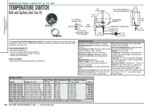
Pressure Limit: 300 psi (20.6 bar).
Deadband: Adjustable from minimum in
Enclosure Rating: General purpose. model chart to full range. Optional low
Optional weatherproof and explosion- fixed deadband.
proof.
Capillary: 6´ (1.8 m) standard. Ranges
Repeatability: ±1% FS.
1N to 7N, and 10N: copper. Ranges 8N,
Switch Type: SPDT snap switch.
9N, 11N: 304 SS.
Optional DPDT snap and a variety of
VIEW #1
2 [50.80]
1-5/8 [41.28] SEE VIEW #1
Ø17/64 [6.75] MOUNTING HOLES
TYP 2 PLACES
3-5/16 [84.14]
3/4 [19.05] CLEARANCE FOR COVER REMOVAL
ADJUSTMENT SCREWS 1/4 MALE NPT CONNECTION 3/4 MALE NPT BULB CONNECTION
Set Point Adjustment: External knobs
Temperature Limit: Process: See model for set point and reset point.
chart; Ambient: 180°F (82°C).
恒温加热器使用说明书

恒温加热器使用说明书一、产品介绍恒温加热器是一种用于控制温度的设备,适用于实验室、工业生产等领域。
本产品采用先进的温度传感器和控制技术,能够实现精确的温度控制,具有稳定性好、操作简单等特点。
二、安全注意事项1. 本产品需在干燥、通风良好的环境下使用。
2. 请确保电源连接正确,接地可靠,以确保使用安全。
3. 仔细阅读产品说明书,并按照说明进行正确操作,避免不必要的事故发生。
4. 使用过程中应避免遮挡散热孔,避免过载使用。
5. 使用结束后,请拔掉电源插头,确保设备断电。
三、产品特点1. 温控范围广:本产品的温控范围可根据需要进行调整,满足不同的实验需求。
2. 温度稳定性好:经过精确的温度控制算法设计,保证设备稳定运行,提供精确的温度控制。
3. 操作简单:本产品采用触摸屏设计,界面简洁清晰,操作便捷,即使对设备不熟悉的用户也能够轻松上手使用。
4. 故障自诊断:设备具有故障自诊断功能,一旦出现故障,会自动报警并显示故障原因,方便用户快速排除故障。
四、使用方法1. 打开设备:接通电源后,按下电源按钮,待设备开机完成后进入待机状态。
2. 设置温度:通过触摸屏上的温度调节按钮,可自定义所需温度。
设定后,系统会根据设定值进行温度控制。
3. 启动加热:设定好温度后,点击启动加热按钮,设备将开始加热,并根据设定温度进行温度调节。
4. 监控温度:设备运行时,观察触摸屏上显示的实时温度值,确保温度始终在设定范围内。
5. 结束使用:使用完毕后,点击停止加热按钮,设备会停止加热并保持待机状态。
拔掉电源插头,确保设备断电。
五、故障排除1. 故障自诊断:设备出现故障时,会自动报警并显示故障原因,用户可根据报警信息进行故障排除。
2. 联系售后服务:若设备故障无法解决,请联系售后服务中心进行维修或更换。
六、维护保养1. 定期清洁:使用过程中请保持设备干燥,避免积尘。
定期用软布擦拭设备外壳,以保持清洁。
2. 防止碰撞:使用过程中请避免撞击设备,以免损坏设备外壳或内部元件。
LED同步控制系统MCTRL R5用户手册英文版

MCTRL R5Independent ControllerProduct Version:V1.0.1Document Number: NS110100550User ManualXI 'AN N OVA S T AR T EC HCO .,L T D.Copyright © 2018 Xi’an NovaStar Tech Co., Ltd. All Rights Reserved.No part of this document may be copied, reproduced, extracted or transmitted in any form or by any means without the prior written consent of Xi’an NovaStar Tech Co., Ltd.Trademarkis a trademark of Xi’an No vaStar Tech Co., Ltd.StatementYou are welcome to use the product of Xi’an NovaStar Tech Co., Ltd. (hereinafter referred to as NovaStar). This document is intended to help you understand and use the product. For accuracy and reliability, NovaStar may make improvements and/or changes to this document at any time and without notice. Any problem in use or any good suggestion, please contact us through ways provided in the document. We will do our utmost to solve the problems and adopt the suggestions after evaluation as soon as possible.X I'A NN OV AS TA RT EC HC O.,LT D.User Manual Change HistoryChange HistoryX I'A NN OV AS TA RT EC HC O.,ContentsChange History ................................................................................................................................ ii 1 Safety ............................................................................................................................................... 1 2 Overview ......................................................................................................................................... 2 3 Hardware Structure.. (3)3.1 Appearance .................................................................................................................................................. 3 3.2 Dimensions .. (5)4 Homepage ....................................................................................................................................... 6 5 Menu Operations .. (8)5.1 Brightness Adjustment ................................................................................................................................. 8 5.2 Screen Settings ........................................................................................................................................... 8 5.2.1 Quick Configuration .................................................................................................................................. 8 5.2.2 Advanced Configuration ........................................................................................................................... 9 5.2.3 Image Offset ............................................................................................................................................. 9 5.3 Rotation Settings ....................................................................................................................................... 10 5.4 Input Settings ............................................................................................................................................. 10 5.4.1 Input Video Source Settings ................................................................................................................... 10 5.4.2 Input Resolution Settings ........................................................................................................................ 10 5.5 Display Control ........................................................................................................................................... 11 5.6 Advanced Settings ...................................................................................................................................... 11 5.6.1 Mapping Function .................................................................................................................................... 11 5.6.2 Loading Cabinet Files .............................................................................................................................. 11 5.6.3 Alarm Threshold ...................................................................................................................................... 12 5.6.4 Saving to Hardware ................................................................................................................................ 12 5.6.5 Redundancy ............................................................................................................................................ 13 5.6.6 Preset Template ...................................................................................................................................... 13 5.6.7 Hot Backup for Input Source .................................................................................................................. 13 5.6.8 Factory Reset ......................................................................................................................................... 13 5.6.9 Go Homepage (s) ................................................................................................................................... 13 5.6.10 Greyscale Adjustment ........................................................................................................................... 13 5.6.11 Hardware Version ................................................................................................................................. 13 5.7 Communication Settings ............................................................................................................................ 13 5.8 Language (14)XI 'AN NOVA S T AR T EC HCO .,L T D.6 Specifications (15)X I'A NN OV AS TA RT EC HC O.,LT D.User Manual 1 Safety1 SafetyTo avoid potential hazards, please use this product according to regulations. Poweroutlet should be installed near the unit and easy to reach. In the event of breakdowns,only trained personnel may disassemble it for maintenance, and please contact theafter-sales department of NovaStar for help.High-voltage hazard: Operating voltage of this product ranges from 100V to 240 V AC.Grounding: Ground connection of this product is enabled through powercords. Please make sure that ground conductors are in good condition.Electromagnetic interference: Keep this product far away from magnets,motors and transformers.Moisture proof: Keep this product in a dry and clean environment. Incase of liquid immersion, please pull the power plug out immediately.Keep the product away from flammable and explosive hazardoussubstances.Prevent liquids or metal fragments from dropping into the product inorder to avoid accidents.X I'A NN OV.,LT D.User Manual 2 Overview2 OverviewDeveloped by NovaStar, the MCTRL R5 is the first independent controller thatsupports rotation function. With up to 3840×1080@60Hz loading capacity of a singleunit, it can support any custom resolution within this range as required, thus meetingthe on-site configuration requirements of extra-long or extra-large LED displays.The MCTRL R5 supports HDMI, Dual Link DVI, SDI signal inputs, as well as 8Neutrik Gigabit Ethernet ports, and 2 optical fiber outputs.The distinctive and innovative design of the MCTRL R5 enables screen configurationwithout PC, diverse image rotation effects, and amazing visual experience for users.Note: The device must be powered off before connection.To control multiple MCTRL R5 units (10 units at most), please cascade them according to the figure below.X I'A NN OV AS TA RT EC HC O.,LT D.3Hardware Structure3.1 AppearanceFront PanelInstruction on knob operations:On the home screen, pressing the knob enters the main menu.XI 'AC HCO .,L T D.● On the main menu, rotating the knob selects a menu item or adjusts theparameter, and pressing the knob confirms the selection or enters the submenu. ●Holding down the knob and BACK button simultaneously for 5 seconds locks or unlocks all the buttons.Rear PanelNote : Type-A USB port is prohibited from being connected to the upper computer directly.XI 'A3.2 DimensionsUnit: mmX I'A NN OV AS TA RT EC HC O.,LT D.4HomepageAfter the MCTRL R5 is powered on, the home screen is shown in the figure below.Power voltage of the motherboard Temperature inside the deviceScreen brightnessXI 'AA S T AR T E C HCO .,L T D.1~2 Optical fiber ports connection: ●●//Control ports:Connects to USB/ Ethernet/ GenLock synchronization/Rotation enabled/lockedX I'A NN OV AS TA RT EC HC O.,5 Menu OperationsMCTRL R5 features powerful functions and simple operations. To achieve betterdisplay effects, users can choose to set other options in the menu.5.1 Brightness AdjustmentOn the main menu, press the knob to select the Brightness item and rotate the knobto adjust the brightness value.5.2 Screen Settings5.2.1 Quick ConfigurationBefore you start, load the cabinet configuration files and save them to the receivingcard.Step 1 Press the knob to enter the main menu.Step 2 Choose Screen Settings > Quick Config to enter the submenu, and rotate the knob to set corresponding options.●Set the row and column quantity of cabinets based on the actual condition of ascreen.●Set the cabinet quantity connecting to port 1. There are limits on the loadingcapacity of ports. Refer to a) in Note for details.●Set data flow of the screen, and refer to c), d), and e) in Note for details.X I'A NN OV AS TA RT EC HC O.,LT D.5.2.2 Advanced ConfigurationStep 1 Choose Advanced Config and press the knob to enter its submenu.Step 2 On the warning screen, click Yes to enter the advanced configuration screen. Step 3 Select Enable and set the parameters of targeted Ethernet ports.5.2.3 Image OffsetSet the horizontal offset and vertical offset of devices ’ loading image.XI 'AN N OVA S5.3 Rotation SettingsThere are 2 rotation methods: Port rotation and screen rotation.●Port rotation: Rotation of cabinets loaded by an Ethernet port (For example, set the rotation angle of port 1, and the cabinets loaded by port 1 will rotate according to the angle).●Screen rotation: Rotation of the whole LED screen according to the rotation angle set before.Rotation settings:Step 1 Choose Rotation Settings > Rotation Enable , and choose ENABLE . Step 2 Choose Port Rotate or Screen Rotate and set parameters. Step 3 Select Save to save your settings.Notes:● Hardware screen configuration is required to be done before the rotation settings. ●After screen configuration are done on SmartLCT, set rotation function on MCTRL R5, and a message “Reconfig screen . Are you sure?” will appear. Choose Yes to perform rotation settings.5.4 Input Settings5.4.1 Input Video Source Settings There are several types of input sources available for users to choose.5.4.2 Input Resolution Settings There are 2 methods to set input resolution:Method 1: Preset resolution Choose a proper resolution from the preset standard resolutions, or use method 2 tocustomize the resolution.Method 2: Custom resolutionRotate the knob to set the custom width (growing in even numbers), custom height, and custom refresh rate, and choose Apply . Press the knob to confirm the setting. If Apply is not enabled, the custom resolution is invalid.XI 'A N N O V A S T AR T EC HCO .,L T D.5.5 Display ControlNormal: Playing the input source normally. Black Out: The screen is black out, with no display. Freeze: Freezing the displaying image.Test Pattern: 8 test patterns including pure color and lines testing.Image Settings: Setting red, green and blue brightness, color temperature, Gamma rate, and saving parameters.5.6 Advanced SettingsAdvanced settings include settings of multiple main functions, as shown below.5.6.1 Mapping FunctionWhen Mapping Function is enabled, each of the cabinets will display the cabinet number and Ethernet port number it belongs to.5.6.2 Loading Cabinet FilesConnect to PC and start NovaLCT on PC, and import the saved cabinet configuration files.Step 1 Save cabinet configuration files.After configuring the receiving cards, click Save to File to save the cabinet configuration files (.rcfgx) to local PC.XI 'AN N OVA S T AR T EC HCO .,L T D.Step 2 Import the cabinet configuration files to the MCTRL R5.Note: After entering the Configuration File of Controller Cabinet Import window, NovaLCTwill automatically read the configuration files already existed in the MCTRL R5. Users can change the names and orders of these files or delete them.Step 3 Load the cabinet configuration files.5.6.3 Alarm ThresholdSet the ranges of temperature and voltage values.5.6.4 Saving to HardwareSave all the configurations related to the receiving cards to the receiving cards and those data will not be lost even after the device is powered off.XI 'AN N OVA S T AR T EC HCO .,L T D.5.6.5 RedundancySet the current device as the primary or backup device.5.6.6 Preset TemplateSave configuration information, rotation parameters, and user settings information astemplates. Users can add 10 templates at most.5.6.7 Hot Backup for Input SourceSet backup source for the current input source. The backup source should be othertypes of input source supported by the device.5.6.8 Factory ResetReset the current device to factory settings.5.6.9 Go Homepage (s)The current page stays for how many seconds before going homepage when there isno actions.5.6.10 Greyscale AdjustmentAdjust greyscale among the range from 4 to 15 for the LED display screen.5.6.11 Hardware VersionView the hardware version of current device. In case of new version release, accessNovaLCT through PC to upgrade the hardware version.5.7 Communication SettingsSet the communication mode and network parameters.Two communication modes are provided: USB Preferred and LAN Preferred. When the USB and Ethernet ports are connected at the same time, the system will use the communication mode set by the user.X I'A NN OV AS TA RT EC HC O.,LT D.Network settings include manual mode and auto mode. When setting the networkmanually, the IP address of current device cannot conflict with IP addresses of otherdevices.5.8 LanguageChange the UI language of the MCTRL R5 unit.X I'A NN OV AS TA RT EC HC O.,LT D.User Manual 6 Specifications6 SpecificationsX I'A NN OV AS TAD.。
泳池和温泉加热器D-2产品说明书

INSTALLATION & OPERATINGINSTRUCTIONSSWIMMING POOL & SPA HEATER D-2Catalog No. 6000.57.1FEffective: 04-30-14Replaces: 12-13-11P/N 241243 Rev. 5WARNING:If these instructions are not followed exactly, a fire or explosion may result causing property damage, personal injury or death.Do not store or use gasoline or other flammable vapors and liquids in the vicinity of this or any other appliance.WHAT TO DO IF YOU SMELL GAS:• Do not try to light any appliance.• Do not touch any electrical switch; do not use any phone in your building.• Immediately call your gas supplier from a neighbor's phone. Follow the gas supplier's instructions.• If you cannot reach your gas supplier, call the fire department.Installation and service must be performed by a qualified installer, service agency or the gas supplier.This manual should be maintained in legible condition and kept adjacent to the heater or in a safe place for futurereference.Rev. 5reflects the following:Changes to:Photo on page 1, “Receiving Equipment” on page 3, “Dimensions” drawing on page 4, Illustrated Parts List on pages 22-23Additions:NoneDeletions:None2RECEIVING EQUIPMENTOn receipt of your equipment, it is suggested that you visually check for external damage to the carton.If the carton is damaged, it is suggested that a note be made on the Bill of Lading when signing for equipment.Remove the complete assembly from the carton. If it is damaged, report the damage to the carrier immediate-ly. Be sure that you receive the number of packages indicated on the Bill of Lading. Claims for shortages and damages must be filed with the carrier by consignee.Purchased parts are subject to replacement only under the manufacturer’s warranty. Debits for defec-tive replacement parts will not be accepted and defective parts will be replaced in kind only per our standard war-ranties.When ordering parts, you must specify the kit number. When ordering under warranty conditions, youmust also specify the date of installation.The manufacturer recommends that this manual be reviewed thoroughly before installing the D-2 PowerVent. If there are any questions which this manual does not answer, please contact you local Representative.The D-2 Power Vent is tested and certified to the latest edition of the American National Standard ANSIZ21.56standard for pool heaters.The D-2 Power Vent is a fan-assisted combustion system designed for application to heater models 206thru 408. When installed as directed, the unit is capable of operating in applications such as through-the-wall venting and reduced horizontal and vertical vent pipe sizes in new and existing installations.The D-2 Power Vent includes a blower with a 120/240 volt 60Hz 1.95/1.0A 3200 RPM motor and aplenum, complete with a draft proving switch and a motor relay.GENERAL SPECIFICATIONSD-2 Power Vent (with Adapter in place)Elbow with Screen Collar AdapterComes separated (assembles together)4” Adapter4INSTALLATION REQUIREMENTSFailure to install, maintain and/or operate the Power Vent in accordance with manufacturer’s instructionsmay result in conditions which can produce bodily injury and property damage.The equipment must be installed by a qualified installer in accordance with all local codes, or, in theabsence of local codes, with the latest edition of the National Fuel Gas Code, ANSI Z223.1/NFPA 54and the National Electrical Code, ANSI/NFPA 70. In Canada, installations must conform to CAN/CSA B149.1 and to the latest Canadian Electrical Code Part 1.Disconnect power supply when making wiring connections or when working around the fan blade andmotor. Failure to do so may result in severe personal injury and equipment damage.Make certain the power source is adequate for the fan motor requirements. Do not add the Power Ventto a circuit where the total load is unknown.DIMENSIONS5INSTALLATION1.Start off by disconnecting main power to the heater.2.Remove the front door from the heater. See Fig. 1.3.If this is a retro-fit application, remove existing “Pagoda Top” and discard. See Fig. 2. If equipped with adrafthood, refer to drafthood installation manual for removal process.4.Remove the (6) Phillips screws that hold the jacket top to the heater. See Fig. 3.5.Lift the rear end of the jacket top while inserting the collar adapter. See Fig. 4 & 5.Note: Brackets are positioned underneath the collar adapter to capture the smaller model, See Fig. 6. Alsonote the orientation of the adapter on the heater as shown in Fig. 7.Pagoda TopFig. 1Fig. 2Fig. 3Fig. 4Fig. 5Fig. 6hold collar adapter in placeRemove door by unfastening knurled screw shown.INSTALLATION (Continued)6.Lower the jacket top back onto the heater and reinstall the (6) Phillips screws. See Fig. 3.7.If installing on a model 266, 267, 268, 406, 407 or 408 heater, skip step 8.8.Turn the Power Vent upside down. Using a 5/16” nut driver, relocate the mounting brackets as shown in Fig. 8.9.Place the Power Vent on top of the heater. See Fig. 9.10.Move the Power Vent, so that the collar adapter slips into the Power Vent. See Fig. 10.11. Push in all four bracket tabs, so the Power Vent locks into position. See Fig. 11.ing a 5/16” nut driver, remove the transformer cover located on the right side of the heater.See Fig. 12.Rear of HeaterFig. 7Fig. 9Fig. 10Fig. 11Fig. 12Front ofHeater6INSTALLATION (Continued)13. Install the right side outdoor conduit through the top 7/8” hole located on the right side of the heater. See. Fig. 13. Note: You must first remove the 7/8” plug on the heater to install the hard conduit. 14. Wire the heater power lines along with the D-2 Power Vent power lines to the supply power per Fig. 15 for 010744 or 010745, and per Fig. 16 for 009832 or 009833. If the D-2 does not match the power supplied, re-wire the blower for the correct voltage.15. Reinstall the transformer cover. See Fig. 12.16. Install the left side outdoor conduit through the top 7/8” hole located on the left side of the heater. See Fig. 14. Note: You must first remove the 7/8” plug on the heater to install the conduit.Power VentPower SupplyFig. 13Fig. 1478INSTALLATION (Continued)17.Remove the (4) Phillips screws that hold the control panel to the heater and lower the control panel. SeeFig. 17.18.Remove and replace the 7/8” plug with the provided 7/8” grommet (located on the left side of the controlpanel). See Fig. 18.19.Route the 24 VAC harness through the 7/8” grommet, See Fig. 19.20.Continue to route the harness down through any available grommet hole. See Fig. 20.21.Wire the harness along with the installed gas valve harness per the wiring diagram.22.Reinstall the (4) Phillips screws that hold the control panel to the heater. See Fig. 17.23.Place the front door back onto the heater. Refer to Fig. 1.Fig. 19Fig. 20NOTE:For Professional heaters, models 268 and 408, it may be necessary to reroute the flexible conduit toeither side of the power vent.Fig. 17Fig. 18Access ScrewAccess Screw7/8” Supplied GrommetVENTINGThe D-2 Power Vent operates with a positive vent static pressure and with a vent gas temperature that prevents excessive condensate production in the vent, and as such, is a CATEGORY III appliance.The total length of run shall not exceed an equivalent length of 100 ft including the termination cap. For all cases, each 90° elbow reduces the maximum vent run by 10 ft and each 45° elbow reduces the run by 5 ft. The vent must be installed properly to prevent the flue gas leakage within the heater. The vent pipe must be suitable for use with Category III Appliances which have flue gas temperatures of less than 400°F. Care must be taken dur-ing the assembly to ensure that all joints are properly sealed.For appliances installed in extremely cold climates, it is recommended that:a) The vent be installed with a slight upward slope of not more than 1/4” per foot of horizontal run to thevent terminal. In this case, an approved condensation trap must be installed per applicable codes.b) The vent be insulated through the length of the horizontal run.The exit terminal of the D-2 Power Vent shall not be less than 7 ft above grade where located adjacent to pub-lic walkways. It must also be at least 3 ft above any forced air inlet located within a 10 ft radius.910U.S. Installations1Canadian Installations2A Clearance above grade, veranda, porch, deck, or balcony1 ft (30 cm)1 ft (30 cm) B Clearance to window or door that may be opened4 ft (1.2m) below or to side of opening; 1 foot (30 cm)above opening3 ft (91 cm)C Clearance to permanently closed window * *D Vertical clearance to ventilated soffit located above the terminal within a horizontal dis- tance of 2 ft (61cm) from the centerline of the terminal5 ft (1.5m)* E Clearance to unventilated soffit * * F Clearance to outside corner * *G Clearance to inside corner6 ft (1.83m)*H Clearance to each side of center line ex- tended above meter/regulator assembly * I Clearance to service regulator vent outlet*6 ft (1.83m) J Clearance to non-mechanical air supply inlet to building or the combustion air inlet to any other appliance 4 ft (1.2m) below or to sideof opening; 1 ft (30 cm) above opening 3 ft (91 cm) K Clearance to mechanical air supply inlet 3 ft (91 cm) above if within 10 ft (3m) horizontally6 ft (1.83m) L Clearance above paved sidewalk or paved driveway located on public property7 ft (2.13m)7 ft (2.13m) t MClearance under veranda, porch, deck or balcony*12 in. (30 cm) T T1 In accordance with the current ANSI Z223.1/NFPA 54 National Fuel Gas Code 2In accordance with the current CAN/CSA-B149 Installation Codes t Vent terminal shall not terminate directly above sidewalk or paved driveway located between 2 single family dwellings that se r vesboth dwellingsTT Permitted only if veranda, porch, deck, or balcony is fully open on a minimum of two sides beneath the floor and top of term i nal andunderside of veranda, porch, deck or balcony is greater than 1 ft (30cm) * Clearances in accordance with local installation codes and the requirements of the gas supplier3 ft (91 cm) within a height 15 ft above the meter/regulator assemblyMinimum Clearances from Vent/Air Inlet Terminations—Indoor and Outdoor InstallationsVent/Air Inlet Termination ClearancesVENTING (Continued)VENTING (Continued)VENTING (Continued)VENTING (Continued)SEQUENCE OF OPERATIONOn call for heat, the PC board will go through its safety chain (water pressure switch, high limit 1 & 2, roll-out, etc.). When the safety chain is closed, the IID pilot will begin to spark and the pilot gas valve will open. A flame will be lit at the pilot assembly. When an acceptable signal is sent back to the PC board, proving the rectifica-tion, the D-2 Power Vent blower will start. When the blower comes up to speed, a draft proving switch will close to allow the main gas valve on the heater to open. Note: On Low NOx units, the main gas valve & combustion blower will turn on simultaneously. A heater with a D-2 Power Vent will continue to operate until call for heat is satisfied.DRAFT-PROVING SWITCHThe draft-proving switch ensures that the blower is operating. Once the D-2 Power Vent is wired to the heater, the switch does not allow the PC board to open the main gas valve, unless it is closed.WIRINGThe D-2 Power Vent includes a wire harness which provides quick connections with the respective controls in the appliance control box. The harness is of sufficient length to fit the unit for which it is sized.Reference the connection diagrams on pages 17 & 18 or the wiring diagrams on pages 19 through 21 for actu-al connections.RELAYAIRPRESSURE SWITCHGAS VALVEY/BKY/BK Y/BK V/BKV/BKV/WV/BK V/WWIRING (Continued)WIRING (Continued)WIRING DIAGRAM – MODELS 207A, 267A, 337A, 407AWIRING DIAGRAM – MODELS 206A, 266A, 336A, 406AWIRING DIAGRAM – MODELS 268, 40822REPLACEMENT PARTSNOTE:To supply you with the correct part, it is impor-tant that you supply the heater model number, serial number and type of gas when applicable.Any part returned for replacement under standard company warranties must be properly tagged with a return parts tag, completely filled in with the heater serial number, model number, etc., and shipped to the Company freight prepaid.If determined defective by the Company and within warranty, a like part or equal substitution will be returned, freight collect. Credit will not be issued.MANUFACTURER:2151 EASTMAN AVENUE OXNARD, CA 93030ILLUSTRATED PARTS LIST123456789101112131415162324Raypak, Inc., 2151 Eastman Avenue, Oxnard, CA 93030 (805) 278-5300 Fax (805) 278-5468Litho in U.S.A.。
单LED灯泡浴台601011CH商品说明书
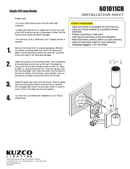
INSTALLATION SHEET601011CHSingle LED Lamp Vanity19054 28th Avenue Surrey, BC Canada V3Z 6M3T: 604 538 7162 TF: 1-855 85 KUZCO F: 604 538 7196 W: 201503311.Remove the fixture from its original packaging. Remove the canopy mounting plate from within the canopy and attach it to the electrical junction box, and wall, using the screws provided in the hardware package.2.Attach the canopy to the mounting plate, which is attached to the electrical junction box on the wall. First attach all wiring with the provided marrets (white to white “N”, black to black “L”, ground to ground “G”). Push the canopy onto the mounting plate, then insert the screw into the holes on the top and bottom of the canopy, once inserted, screw in the screws provided to secure the fixture to the wall.3.Install the glass light cover onto the fixture. Take the glass light cover and guide it gently onto the fixture. Carefully turn the glass light cover in a clockwise motion in order to screw it firmly into place (do not over tighten).4.You have now completed the installation of your fixture, please enjoy.Please Note:• All Kuzco LED fixtures come with pre-wired LED module(s).• Unless instructed to do so, please do not touch any part of the LED module(s) as any unnecessary contact with the module could cause permanent damage.• For dimming, an ELV (Electronic Low Voltage) dimmer is required.3.1.2.。
迪拜保温盒LED模具系列说明书
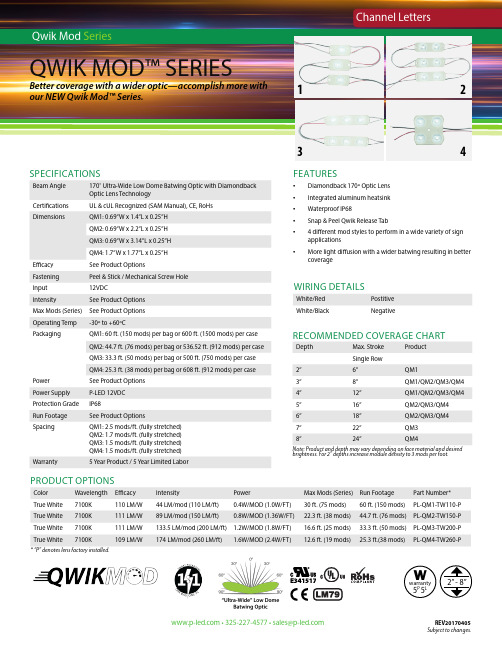
FEATURES• Diamondback 170º Optic Lens• I ntegrated aluminum heatsink• Waterproof IP68• Snap & Peel Qwik Release Tab• 4 different mod styles to perform in a wide variety of sign applications• More light diffusion with a wider batwing resulting in better coverageSPECIFICATIONSBeam Angle 170˚ Ultra-Wide Low Dome Batwing Optic with DiamondbackOptic Lens TechnologyCertifications UL & cUL Recognized (SAM Manual), CE, RoHsDimensions QM1: 0.69”W x 1.4”L x 0.25”HQM2: 0.69”W x 2.2”L x 0.25”HQM3: 0.69”W x 3.14”L x 0.25”HQM4: 1.7”W x 1.77”L x 0.25”HEfficacy See Product OptionsFastening Peel & Stick / Mechanical Screw HoleInput12VDCIntensity See Product OptionsMax Mods (Series)See Product OptionsOperating Temp-30º to +60ºCPackaging QM1: 60 ft. (150 mods) per bag or 600 ft. (1500 mods) per caseQM2: 44.7 ft. (76 mods) per bag or 536.52 ft. (912 mods) per caseQM3: 33.3 ft. (50 mods) per bag or 500 ft. (750 mods) per caseQM4: 25.3 ft. (38 mods) per bag or 608 ft. (912 mods) per casePower See Product OptionsPower Supply P-LED 12VDCProtection Grade IP68Run Footage See Product OptionsSpacing QM1: 2.5 mods/ft. (fully stretched)QM2: 1.7 mods/ft. (fully stretched)QM3: 1.5 mods/ft. (fully stretched)QM4: 1.5 mods/ft. (fully stretched)Warranty 5 Year Product / 5 Year Limited LaborPRODUCT OPTIONSColor Wavelength Efficacy Intensity Power Max Mods (Series)Run Footage Part Number*True White7100K110 LM/W44 LM/mod (110 LM/ft)0.4W/MOD (1.0W/FT)30 ft. (75 mods)60 ft. (150 mods)PL-QM1-TW110-P True White7100K111 LM/W89 LM/mod (150 LM/ft)0.8W/MOD (1.36W/FT)22.3 ft. (38 mods)44.7 ft. (76 mods)PL-QM2-TW150-P True White7100K111 LM/W133.5 LM/mod (200 LM/ft) 1.2W/MOD (1.8W/FT)16.6 ft. (25 mods)33.3 ft. (50 mods)PL-QM3-TW200-P True White7100K109 LM/W174 LM/mod (260 LM/ft) 1.6W/MOD (2.4W/FT)12.6 ft. (19 mods)25.3 ft.(38 mods)PL-QM4-TW260-P•325-227-4577•***************REV20170405WIRING DETAILSWhite/Red PostitiveWhite/Black Negative1234RECOMMENDED COVERAGE CHARTDepth Max. Stroke ProductSingle Row2”6”QM13”8”QM1/QM2/QM3/QM44”12”QM1/QM2/QM3/QM45”16”QM2/QM3/QM46”18”QM2/QM3/QM47”22”QM38”24”QM4Note: Product and depth may vary depending on face material and desiredbrightness. For 2” depths increase module density to 3 mods per foot.Wwarranty5P 5L* “P” denotes lens factory installed.Subject to changes.。
LED恒温加热平台说明书(英文版)
Thermostatic Heater IllustrationI. Item description:∙Adopted by original Yudian Automation PDI economic type temperature controller, its high-accuracy, operation is safe, simple, clear and convenience.∙Adopted by original high-quality AC solid-state relay, long lasting as 100 times of the common contact relay.∙Adopted by multiple high-quality metal heating pipes, maintenance is convenience and low failure-rate.∙The aluminum top surface is high thermal conductivity, heat fast and evenly.∙The whole case is made by high-quality SUS304 stainless to ensure it against from rusted and peeling off in the usual condition.II. SpecfationPower Supply: 220V (50HZ);Controllable Temperature Range: Basic Type (Ordinary Temperature~350℃); Elevated Temperature Type( Ordinary Temperature~450℃), Ultra Temperature Type (Ordinary Temperature~500℃), Each type of the item has Unitary Type (Model A), Splitting Type (Model B) and Guardrail Type ( Model C).III. Application filed∙Electronic industrial bonding sealing and application heating.∙LED industrial aluminum base welding and maintenance∙mold core pre-heating∙Essential equipment at the laboratory in various industrials such as biology, genetics, medicine and environment etc.IV. Application Instruction∙Plug in the power and turn on the POWER switch while the RED indicator light constant light, its means the device has being powered.∙Turn on the HEATING switch and the device is starting then, GREEN indicator light constant light, it’s means the device is heating up; sparkling means it has been into the constant temperature while workstation is being recycle heating up.∙Once it finish using, please turn off the HEATING switch first and the device will be stopped heating, while the RED indicator light are still constant light in order toreminding the device are still working and please don’t touch the work surface. Wait for the work surface being cool down (suggesting after an hour) and torn off thePOWER switch then.V. Attention:∙Voltage must be 220V, please use the 3 pole socket which is connect to the earth and with anticreeping switch as well.∙Please don’t open the case or switch any wire position unless you are the specific operation.∙Hand touch is prohibited in case to avoid burn.∙Please unplug the power supply when the people away or device has being long term idle.∙Please keep the vent hole clean since the device has been cooperated with fan cooler,∙Please make sure it has unplugged from the power source when the fuse needs to be replaced for safety.VII. Parameter Setting●Set value setting: Press the key ∧,∨,<to modify the control value which isshowing at the display window under the default situation, press the key ∨ for value reducing, press the key ∧ for value increasing, the dot sparkly with the number which position switched( sparkly like cursor). Press down for quick increase / reduce value, and the value will be speed up while the position of the dot rightward switch. Press the key <to move and modify the position of the value (cursor). Press the key ∧ or ∨ to modify the value which is sparkly, control convenience.●Automatic adjustable (AT) operation, available with Automatic (AT) operating toconfirm the PID adjustable parameter when use AI agronomical PID control. The AT parameter shows up after press the key <at 2 seconds under the default situation.Press the key ∧ to modify the OFF to ON which is shown at the bottom displaywindow, the Automatic Adjustable operation will be start by press the key “O” toconfirm. At the same time, the letter “AT” will be sparking at the display window which is at the bottom of instrument panel, the result of the suitable PID parameter for the current condition will be counted automatically by the local micro CPU of theinstrument panel, and it will be exterminated automatically from the AT operating.Press the key <at another 2 seconds to switch up the AT parameter from ON to OFF and confirmed by press the key “0” to give up the AT operating. (Remarks: The system parameter value are totally different within the different set value, SV valuemodify are prohibited while the AT operating in process. The control result might be not the best once the AT operation finished, it will be got the best result after use in a whileNonstandard specification is available to booking with 5~7 working days lead-timeVIII, Guarantee●12 months guaranteed for the complete device (6 months for heating pipe) beyondhuman control.●Lifetime beneficial service after guarantee.Note:●Please make sure the connector plug is plug in fastened, no shaking movement,otherwise the power socket will be burned by the spark.●The temperature might be 3-5 degrees higher than the setting number and it willbe back to it after few minutes, this feature could be increase the uniformity ofheating panel temperature.●Since the heating panel is machined goods, there has some machine oil left atthe screw hole and it would be some smoke with smell comes up after burning bythe high temperature, this is normal phenomenon and will be disappeared after aperiod.●Please ignore the noise when this equipment running, it’s because of g rating thatthe heating pipe rubs against with panel during the situation of substancesexpand when heated and contract when cooled.●There are 2 fuses inside the equipment to ensure the safety.●It has been took 24 hours for burn-in test before out-going of the factory, pleasedon’t change the default parameter without authorized,otherwise ourassociation will take no responsibility and liability.。
900 Series LED Scenlight 产品说明书
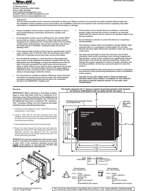
900 Series LED ScenlightFor warranty information regarding this product, visit /warranty©2007 Whelen Engineering Company Inc.Form No. 14144A (031408)Mounting:IMPORTANT!When selecting a mounting location,keep in mind that there must be a minimum of 2"clearance around the perimeter of the lighthead and any vehicle components (insulation,etc.).The rear of the lighthead must have a minimum 1/8"clearance.This increases airflow over the heatsink and helps maintain proper operating temperature.ing the mounting diagram shown,mark off the mounting holes and the “cut-out”area.ing a .250"drill bit,drill the mounting holes then carefully cut and remove the area of the mounting surface as shown.Do not remove the mounting surface where the mounting holes are drilled.3.Insert supplied grommets into the mounting holes.4.Route the cable through the wiring hole and make the appropriate connections.After testing the operation of the lighthead,position the lighthead onto the mounting surface and secure to the vehicle using the four #8x 1½”sheet metal screws provided.WARNING!All customer supplied wires that connect to the positive (+)terminal of the battery must be sized to supply at least 125%of the maximum operating current and FUSED “at the battery”to carry that load.DO NOT USE CIRCUIT BREAKERS WITH THIS PRODUCT!Safety FirstThis document provides all the necessary information to allow your Whelen product to be properly and safely installed. Before beginning the installation and/or operation of your new product, the installation technician and operator must read this manual completely. Important information is contained herein that could prevent serious injury or damage.!Proper installation of this product requires the installer to have a good understanding of automotive electronics, systems and procedures.!If mounting this product requires drilling holes, the installer MUST be sure that no vehicle components or other vital parts could be damaged by the drilling process. Check both sides of the mounting surface before drilling begins.Also de-burr any holes and remove any metal shards or remnants. Install grommets into all wire passage holes.!If this manual states that this product may be mounted with suction cups, magnets, tape or Velcro®, clean the mounting surface with a 50/50 mix of isopropyl alcohol and water and dry thoroughly.!Do not install this product or route any wires in the deployment area of your air bag. Equipment mounted or located in the air bag deployment area will damage or reduce the effectiveness of the air bag, or become a projectile that could cause serious personalinjury or death. Refer to your vehicle owner's manual for the air bag deployment area. The User/Installer assumes full responsibility to determine proper mounting location, based on providing ultimate safety to all passengers inside the vehicle.!For this product to operate at optimum efficiency, a good electrical connection to chassis ground must be made. The recommended procedure requires the product ground wire to be connected directly to the NEGATIVE (-) battery post.!If this product uses a remote device to activate or control this product, make sure that this control is located in an area thatallows both the vehicle and the control to be operated safely in any driving condition.!Do not attempt to activate or control this device in a hazardous driving situation.!This product contains either strobe light(s), halogen light(s), high-intensity LEDs or a combination of these lights. Do not staredirectly into these lights. Momentary blindness and/or eye damage could result.!Use only soap and water to clean the outer lens. Use of other chemicals could result in premature lens cracking (crazing) and discoloration. Lenses in this condition have significantly reduced effectiveness and should be replaced immediately. Inspect and operate this product regularly to confirm its proper operation and mounting condition. Do not use a pressure washer to clean this product.!It is recommended that these instructions be stored in a safe place and referred to when performing maintenance and/or reinstallation of this product.!FAILURE TO FOLLOW THESE SAFETY PRECAUTIONS ANDINSTRUCTIONS COULD RESULT IN DAMAGE TO THE PRODUCT OR VEHICLE AND/OR SERIOUS INJURY TO YOU AND YOUR PASSENGERS!WIRE FUNCTIONS:ColorWhiteBlack orBlack/White Function(+) VBAT (Fuse@5A)(-) Ground (12V)or(-) Ground (24V)Wiring Diagram 3-pos. Socket Conn.Pos.1 - Power-(+)DCV / WHITE(+)Pos.2 - N/C Pos.3 - GroundBLACK (12V models)orBLACK/WHITE (24V models)Pos.1 - Power-(+)DCV / WHITE(+)Pos.2 - Sealing Plug Pos.3 - GroundBLACK (12V models)orBLACK/WHITE (24V models)Wiring Diagram 3-pos. Pin Housing321®ENGINEERING COMPANY INC.51 Winthrop RoadChester, Connecticut 06412-0684Phone: (860) 526-9504SalesEmail:*******************CanadianSales:************************CustomerService:*******************www..comWarnings to InstallersWhelen’s emergency vehicle warning devices must be properly mounted and wired in order to be effective and safe. Read and follow all of Whelen’s written instructions when installing or using this device. Emergency vehicles are often operated under high speed stressful conditions which must be accounted for when installing all emergency warning devices. Controls should be placed within convenient reach of the operator so that he can operate the system without taking his eyes off the roadway. Emergency warning devices can require high electrical voltages and/or currents. Properly protect and use caution around live electrical connections.Grounding or shorting of electrical connections can cause high current arcing, which can cause personal injury and/or vehicle damage, including fire. Many electronic devices used in emergency vehicles can create or be affected by electromagnetic interference.Therefore, after installation of any electronic device it is necessary to test all electronic equipment simultaneously to insure that they operate free of interference from other components within the vehicle. Never power emergency warning equipment from the same circuit or share the same grounding circuit with radio communication equipment.All devices should be mounted in accordance with the manufacturer’s instructions and securely fastened to vehicle elements of sufficient strength to withstand the forces applied to the device. Driver and/or passenger air bags (SRS) will affect the way equipment should be mounted.This device should be mounted by permanent installation and within the zones specified by the vehicle manufacturer, if any.Any device mounted in the deployment area of an air bag will damage or reduce the effectiveness of the air bag and may damage or dislodge the device. Installer must be sure that this device, its mounting hardware and electrical supply wiring does not interfere with the air bag or the SRS wiring or sensors. Mounting the unit inside the vehicle by a method other than permanent installation is not recommended as unit may become dislodged during swerving; sudden braking or collision. Failure to follow instructions can result in personal injury. Whelen assumes no liability for any loss resulting from the use of this warning device. PROPER INSTALLATION COMBINED WITH OPERATOR TRAINING IN THE PROPER USE OF EMERGENCY WARNING DEVICES IS ESSENTIAL TO INSURE THE SAFETY OF EMERGENCY PERSONNEL AND THE PUBLIC.Warnings to UsersWhelen’s emergency vehicle warning devices are intended to alert other operators and pedestrians to the presence and operation of emergency vehicles and personnel. However, the use of this or any other Whelen emergency warning device does not guarantee that you will have the right-of-way or that other drivers and pedestrians will properly heed an emergency warning signal. Never assume you have the right-of-way. It is your responsibility to proceed safely before entering an intersection, driving against traffic, responding at a high rate of speed, or walking on or around traffic lanes. Emergency vehicle warning devices should be tested on a daily basis to ensure that they operate properly. When in actual use, the operator must ensure that both visual and audible warnings are not blocked by vehicle components (i.e.: open trunks or compartment doors), people, vehicles, or other obstructions. It is the user’s responsibility to understand and obey all laws regarding emergency warning devices.The user should be familiar with all applicable laws and regulations prior to the use of any emergency vehicle warning device. Whelen’s audible warning devices are designed to project sound in a forward direction away from the vehicle occupants. However, because sustained periodic exposure to loud sounds can cause hearing loss, all audible warning devices should be installed and operated in accordance with the standards established by the National Fire Protection Association.。
LED灯说明书中英文介绍
第8页光源系列 LAMP Series闪射系列 FLASHING SERIES外形设计美观、烟尘式散热排气孔Beautiful and decent appearance design, Smoke-Dust cooling exhaust hole产品特性 PRODUCTS FEATURES灯体采用6063航空铝材,冷锻式一体成型,外形新颖,美观大方;独有烟尘式散热设计,通过散热排气孔能更快的带走热量,散热效率高;电源采用美国BCD方案设计,高精度智能控制电路,具有过载欠压等保护,使用更安全;进口一体化透镜,透光率高达93%,表面鳞面设计,更好的防止眩光;新型EMC超导热大功率灯珠,具有高光效,高显指,采用陶瓷支架,散热效果更好,将低光衰。
The lamp body is made of 6063 aviation aluminum with novel and beautiful appearance. Product Category: Cold Forging, Integrated molding.Cooling Design: Unique Smoke-Dust Type, it can take away heat faster through the vent holes, so the cooling efficiency is very high.Power source: Using BCD solution design from US with precision smart control circuit, overload & under voltage protection, keeps it more secure.Lens: Integrated lens imported from abroad, light transmission rate is as high as 93%, and the surface design uses Scaly surface, so it can prevent glare much better;New EMC Lamp beads: superconducting heat and high power, high luminance, and high color render index.Ceramic bracket: provides better heat dissipation and low light decay.应用范围商业重点照明、酒店重点照明、装饰照明、专卖店、咖啡厅、KTV、超市、写字楼、书房、面包店、书店、家居等场所。
- 1、下载文档前请自行甄别文档内容的完整性,平台不提供额外的编辑、内容补充、找答案等附加服务。
- 2、"仅部分预览"的文档,不可在线预览部分如存在完整性等问题,可反馈申请退款(可完整预览的文档不适用该条件!)。
- 3、如文档侵犯您的权益,请联系客服反馈,我们会尽快为您处理(人工客服工作时间:9:00-18:30)。
Thermostatic Heater IllustrationI.Item description:Adopted by original Yudian Automation PDI economic type temperature controller, its high-accuracy, operation is safe, simple, clear and convenience.Adopted by multiple high-quality metal heating pipes, maintenance is convenience and low failure-rate.The aluminum top surface is high thermal conductivity, heat fast and evenly.The whole case is made by high-quality SUS304 stainless to ensure it against from rusted and peeling off in the usual condition.II. SpecfationPower Supply:220V (50HZ);Controllable Temperature Range:Basic Type (Ordinary Temperature~350℃); Elevated TemperatureType( Ordinary Temperature~450℃),Ultra Temperature Type (Ordinary Temperature~500℃), Each type of the item hasUnitary Type (Model A), Splitting Type (Model B) and Guardrail Type ( Model C).E,F。
Item NO.Heat Generating Plate PowerNet WeightSpec.SET0550x20mm士1250W(MAX)3.5KgSET10100x20mm士1500W (MAX)4.0 KgSETX150X20MM士1700W(MAX)5.5 kgSET20200x20mm士1900W (MAX)5.2 KgSETx20mm士11500W (MAX)6.5 KgSET30300x20mm士11600W (MAX)7.0 KgSETx250x20mm士11800W (MAX)8.5 KgSETx300x20mm士12000W (MAX)12.5 KgSETx350x20mm士12700W (MAX)21.3 KgSETx400x20mm士13200W (MAX)22.5 KgSETx400x20mm士13500W (MAX)25 KgIII. Application filedElectronic industrial bonding sealing and application heating.LED industrial aluminum base welding and maintenancemold core pre-heatingIV. Application InstructionPlug in the power and turn on the POWER switch while the RED indicator light constant light, its means the device has being powered.Turn on the HEATING switch and the device is starting then, GREEN indicator light constant light, it’s means the device is heating up; sparkli ng means it has been into the constant temperature while workstation is being recycle heating up.Once it finish using, please turn off the HEATING switch first and the device will be stopped heating, while the RED indicator light are still constant light in order to reminding the device are still working and please don’t touch the work surface. Wait for the work surface being cool down (suggesting after an hour) and torn off the POWER switch then.V. Attention:Voltage must be 220V, please use the 3 pole socket which is connect to the earth and with anticreeping switchas well.Please don’t open the case or switch any wire position unless you are the specific operation.Hand touch is prohibited in case to avoid burn.Please unplug the power supply when the people away or device has being long term idle.Please keep the vent hole clean since the device has been cooperated with fan cooler,Please make sure it has unplugged from the power source when the fuse needs to be replaced for safety.VI. Control panel illustrationPV measurement value / model value display <data position switch SV set value / model content value display ∨data reducing OP1out put ∧data increasing AU1alarm 10model set ( enter)AU2alarm 2VII. Parameter SettingPress the key “0” at few seconds to enter the following table:Name illustration setting range Factory Defult HIA Maximum alarm 0-999LOA Minimum alarm 0-999-199HDA tolerance maximum alarm 0-999LOC parameter modify level 0-2550(modify prohibited)Set value setting:Press the key ∧,∨,<to modify the control value which is showing at the display window under the default situation, press the key ∨ for value reducing, press the key ∧ for value increasing, the dot sparkly with the number which position switched( sparkly like cursor). Press down for quick increase / reduce value,and the value will be speed up while the position of the dot rightward switch. Press the key <to move and modify the position of the value (cursor). Press the key ∧ or ∨to modify the value which is sparkly, control convenience.Automatic adjustable (AT) operation, available with Automatic (AT) operating to confirm the PID adjustable parameter when use AI agronomical PID control. The AT parameter shows up after press the key <at 2 seconds under the defaultsituation.Press the key ∧ to modify the OFF to ON which is shown at the bottom display window, the Automatic Adjustable operation will be start by press the key “O” to confirm. At the same time, the letter “AT” will be sparking at the display window which is at the bottom of instrument panel, the result of the suitable PID parameter for the current condition will be counted automatically by the local micro CPU of the instrument panel, and it will be exterminated automatically from the AT operating.Press the key <at another 2 seconds to switch up the AT parameter from ON to OFF and confirmed by press the key “0” to give up the AT operating. (Remarks:The system parameter value are totally different within the different set value, SV value modify are prohibited while the AT operating in process. The control result might be not the best once the AT operation finished, it will be got the best result after use in a whileNonstandard specification is available to booking with 5~7 working days lead-time VIII, GuaranteeLifetime beneficial service after guarantee.Note:Please make sure the connector plug is plug in fastened, no shaking movement,otherwise the power socket will be burned by the spark.The temperature might be 3-5 degrees higher than the setting number and it will be back to it after few minutes, this feature could be increase the uniformity of heating panel temperature.Please ignore the noise when this equipment running, it’s because of grating that the heating pipe rubs against with panel during the situation of substances expand when heated and contract when cooled.There are 2 fuses inside the equipment to ensure the safety.It has been took 24 hours for burn-in test before out-going of the factory, please don’t change the default parameter without authorized,otherwise our association will take no responsibility and liability.。