0-10调光器中文说明书
LED GU10调光灯说明书

Product informationThis range provides a substantial energy saving and gives an effective replacement performance for 35W halogen while consuming only 4.5W of power.Features & Benefits• IEC-size• Dimming range 10% ~ 100%• Available in 2700K, 3000K and 4000K • Lumen output of 170-180-200lm• 25 degree and 35 degree beam angles • Long life for reduced maintenance costs• IR/UV-radiation free, Mercury free, Low heat emissionApplication areasLED GU10 dimmable lamps have massive energy savings versus traditional lamps. Coupled with long life, they are superb replacements where standard incandescent or halogen lamps are in use such as: accent, display and general lighting applications in a commercial, industrial or residential environments.Standards• IEC60357: Tungsten halogen lamps (non-vehicle) –Performance specifications.• IEC62560: Self-ballasted LED lamp for general lighting services voltage 50~250V-safety specification.• IEC62471: Photobiological safety of lamps and lamp systems.• EN55015: Limits and methods of measurement of radio disturbance characteristics of electrical lighting and similar equipment.• EN61547: Equipment for general lighting purposed EMC immunity requirements.• EN61000-3-2: Limits for harmonic current emissions.• EN61000-3-3: Limitation of voltage fluctuations and flicker in low voltage supply systems for equipment with rated current ≤16A.LED DirectionalDimmable GU10 4.5 WattGELightingD A T A S HE ETSpecification summaryWattage (W)Base Product DescriptionCandela (cd)Lumen (lm)Beam Angle (degree)CCT (K)Life hours L70/B10Life hours B50Efficiency (lm/W)Power factor CRI Switch Cycles Pack Qty Product Code 4.5 GU10LED4.5D/GU10/827/220-240V/FL/BX 1/850017025270025,00045,000380.58012,5001/8657754.5 GU10LED4.5D/GU10/827/220-240V/WFL/BX 1/840017035270025,00045,00038 0.58012,5001/8972484.5 GU10LED4.5D/GU10/830/220-240V/FL/BX 1/856018025300025,00045,00040 0.58012,5001/8657774.5 GU10LED4.5D/GU10/830/220-240V/WFL/BX 1/845018035300025,00045,00040 0.58012,5001/8972664.5 GU10LED4.5D/GU10/840/220-240V/FL/BX 1/861020025400025,00045,00044 0.58012,5001/8657804.5GU10LED4.5D/GU10/840/220-240V/WFL/BX 1/850020035400025,00045,000440.58012,5001/897273DimensionsLumen maintenance at rated lifeOperation and maintenanceMaximum T hs recommended• Not for use in totally enclosed fixtures.• Suitable for voltage fluctuations of +/- 10%.• Switch off mains supply before installing/removing lamp.• LED GU10 lamps are dimmable on most common leading edge dimmers, please contact local Sales agent for compatibility.• Safe to use on Photo- & Timer-circuits, please contact local Sales agent for compatibility. • Ambient temperature range -20° C to 40°C.>70% lumen maintenance by 90% of lamps at 25,000 hoursGU10 4.5W Dimmable (IEC-size) 95° CTest point4.5W GU10 LED lamps have the following common features• 220-240V with power factor of 0.5• Complete range with CRI >80 and 6-step MacAdam colour consistency • Efficiency up to 44lm/W• Operating temperature: -20°C to +40°Cø5058.03GE Lighting is constantly developing and improving its products. For this reason, all product descriptions in this brochure are intended as a general guide, and we may change specifications from time to time in the interest of product development, without prior notification or public announcement. All descriptions in this publication present only general particulars of the goods to which they refer and shall not form part of any contract. Data in this guide has been obtained in controlled experimental conditions. However, GE Lighting cannot accept any liability arising from the reliance on such data to the extent permitted by law. LED Directional GU10 4.5W Data Sheet – June 2012/euand General Electric are both registered trademarks of the General Electric CompanyGELightingProduct informationThis range provides substantial energy savings compared to 35W or 50W halogen products by consuming only 5W to 6.5W of power.Features5W – Standard IEC size product with 220-270 Lumen output 6.5W – Large size product with 380-450 Lumen output • Dimmable on most leading and trailing edge dimmers • 45,000 hours life (L70/B50) • Mercury free• 2700K, 3000K and 4000K• 25 degree and 35 degree beam anglesApplication areasLED GU10 dimmable lamps offer massive energy savings versus Halogen GU10 lamps. Coupled with long life, they are superb replacements where halogen lamps are in use such as: accent, display and general lighting applications in a commercial, industrial or residential environments.IEC standardsIEC60357: Tungsten halogen lamps(non-vehicle) –Performance specifications.IEC62560: Self-ballasted LED lamp for general lighting services voltage 50~250V-safety specification.EN60968: Self-Ballast lamps for general lighting services-Safety Requirements.IEC62471: Photobiological safety of lamps and lamp systems.EN55015: Limits and methods of measurement of radio disturbance characteristics of electrical lighting and similar equipment.EN61547: Equipment for general lighting purposed EMC immunity requirements.EN61000-3-2: Limits for harmonic current emissions.EN61000-3-3: Limitation of voltage fluctuations and flicker in low voltage supply systems for equipment with rated current ≤16A.LED DirectionalDimmable GU10 5 Watt and 6.5 WattD A T A S HE E T5GU10LED5D/GU10/827/220-240V/FL 950220252,70045,0004545,0001/8652495GU10LED5D/GU10/827/220-240V/WFL 600220352,70045,0004545,0001/8652505GU10LED5D/GU10/830/220-240V/FL 1,050240253,00045,0005045,0001/8652535GU10LED5D/GU10/830/220-240V/WFL 700240353,00045,0005045,0001/8652545GU10LED5D/GU10/840/220-240V/FL 1,200270254,00045,0005545,0001/8657995GU10LED5D/GU10/840/220-240V/WFL 750270354,00045,0005545,0001/8658016.5GU10LED6.5D/GU10/827/220-240V/FL 1,600400252,70045,0006045,0001/8652526.5GU10LED6.5D/GU10/827/220-240V/WFL 750380352,70045,0006045,0001/8652556.5GU10LED6.5D/GU10/830/220-240V/FL 1,600400253,00045,0006045,0001/8652566.5GU10LED6.5D/GU10/830/220-240V/WFL 750380353,00045,0006045,0001/8652576.5GU10LED6.5D/GU10/840/220-240V/FL 1,800450254,00045,0006545,0001/8652586.5GU10LED6.5D/GU10/840/220-240V/WFL850430354,00045,0006545,0001/865259DimensionsIEC-size GU10Wattage [W]MOL [mm]DIA [mm]557.050.2Large-size GU10Wattage [W]MOL [mm]DIA [mm]6.577.650.2MOL: maximum overall lengthDiameter: maximum lamp diameter Luminaire must be able to support 250gBasic data• ”A” Class Energy Rating • Power factor: 0.8• Colour Rendering Index >80• Colour consistency within 5 steps on MacAdam ellipse • Efficiency from 45lm/W up to 65lm/W •Operating temperature: -20°C to +40°CLumen maintenance at rated lifeMinimum 70% Lumen maintenance at 45,000 hours average Life timeOperation and maintenance• Store and use the lamps the same way as traditional halogen lamps.• Check your fixtures are properly wired and don’t deliver voltage spike to lamps causing overheating/failure.• Lamps should be kept free from contamination.• Good condition of the lamp holder contacts is important to ensure proper operation of lamp.• Ensure lamp is cool before removing.• Switch off mains supply before installing/removing lamp.• L ED GU10 5W and 6.5W lamps are dimmable on many leading edge and trailing edge dimmers. Please visit /dimming-led for a list of compatible dimmers.• Not for use in totally enclosed recessed fixtures.GE Lighting is constantly developing and improving its products. For this reason, all product descriptions in this brochure are intended as a general guide, and we may change specifications from time to time in the interest of product development, without prior notification or public announcement. All descriptions in this publication present only general particulars of the goods to which they refer and shall not form part of any contract. Data in this guide has been obtained in controlled experimental conditions. However, GE Lighting cannot accept any liability arising from the reliance on such data to the extent permitted. LED GU10 Dimmable Data Sheet – December 2012/eu/ledand General Electric are both registered trademarks of the General Electric Company。
自动0-10v电压调光模块工作原理

自动0-10v电压调光模块工作原理0-10V电压调光是一种常用的LED灯控制方式,在不同应用场景下都有很好的效果。
0-10V电压调光主要运用于普通交流电供电的常见场所,如办公室,会议室,家庭等,能够实现照明亮度的控制,同时可以节省能源。
本文将重点讲解0-10V电压调光模块的工作原理。
1. 组件介绍0-10V调光模块主要由三个部分组成:调光器、电源和LED灯。
调光器是0-10V调光模块的核心部分,主要作用是调节LED灯亮度。
电源是提供电能的设备,将220V的交流电转换为合适的直流电压(一般为12V或24V)。
LED灯则是具体实现照明的阳台,其类型、数量、功率等参数取决于实际需要。
2. 工作原理0-10V电压调光模块的工作原理非常简单,主要分为以下步骤:(1) 电源工作:0-10V电压调光模块的电源是将220V的交流电转化为合适的直流电。
在电源工作时,交流电先通过变压器变压,并通过整流器将交流电转换为直流电,存储在电容器中,以保证其稳定性。
然后,直流电流通过电路板上的稳压器,被调整为适合LED灯使用的电流,并供给给LED灯。
(2) 调光器工作:调光器是0-10V调光模块的核心部分,其主要作用是控制LED灯的亮度。
在调光器工作时,它接收从控制器或0-10V的信号,并根据信号的大小、变化将合适的电压输出给LED灯。
在调光器中,一般采用的是电容分压的方法实现电压调节。
具体地说,调光器通过利用一个电容分出一个确定的电压,并将其作为反馈信号,保证输出电压的稳定性。
这种模式下,调光器所设置的一组电容可以产生不同的电压,控制LED灯的不同明亮程度,在实现照明的还可以实现节约能源的目的。
(3) LED灯工作:LED灯是0-10V调光模块的实际照明阳台,其工作方式包括两个步骤:直流转换和光学发光。
在直流转换过程中,LED灯接收0-10V调光模块输出的直流电,经过内部芯片的反向保护、驱动电路、电流稳定器等分步处理,并被转换成适合LED灯的电压,实现LED灯的实际发光。
可控硅调光模块与 0-10V调光模块前沿调光后沿调光区别
可控硅调光模块与 0-10V调光模块的区别选用产品简述目前最常用的调光模块有:5A可控硅调光、0-10V调光两种,而其他的调光工作原理是通过控制电流与电压、频率大小的输出达到LED调光功能。
大功率就需要选用调光箱。
类型区别1、可控硅调光模块支持白炽灯、金卤灯、钠灯、LED灯具,需灯具驱动支持调光,调光模式它的工作原理是将输入电压的波形通过导通角切波之后,产生一个切向的输出电压波形。
应用切向的原理,可减少输出电压的有效值,以此来降低普通负载(电阻负载)的功率。
可控硅调光的优点在于工作效率较高,性能稳定。
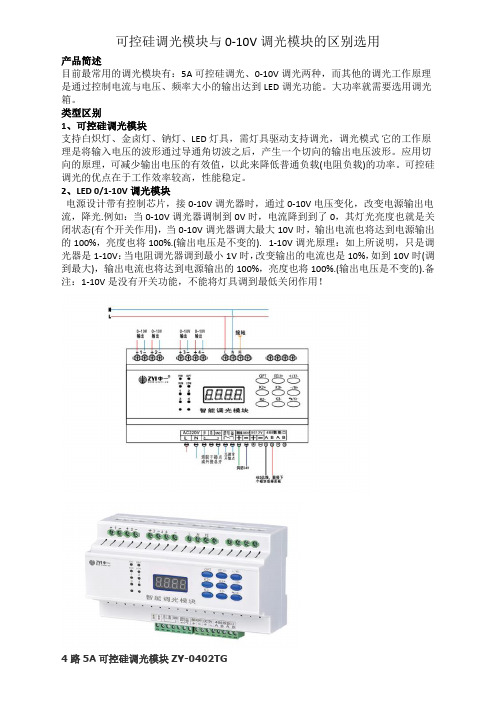
2、LED 0/1-10V调光模块电源设计带有控制芯片,接0-10V调光器时,通过0-10V电压变化,改变电源输出电流,降光.例如:当0-10V调光器调制到0V时,电流降到到了0,其灯光亮度也就是关闭状态(有个开关作用),当0-10V调光器调大最大10V时,输出电流也将达到电源输出的100%,亮度也将100%.(输出电压是不变的). 1-10V调光原理:如上所说明,只是调光器是1-10V:当电阻调光器调到最小1V时,改变输出的电流也是10%,如到10V时(调到最大),输出电流也将达到电源输出的100%,亮度也将100%.(输出电压是不变的).备注:1-10V是没有开关功能,不能将灯具调到最低关闭作用!4路5A可控硅调光模块ZY-0402TG可控制4路1KW的射灯、筒灯和白炽灯等电压调光,输出调光类型为前沿波调光。
性能描述:1、标准35mm导轨式2、具有4路独立输出,每路最大提供5A即1000W3、每个回路具有低端限幅、高端限幅、最大限幅以适应不同的负载4、采用RS485总线,标准Modbus协议4路0-10V信号调光模块ZY-0401TG4路0-10V调光模块可对射灯、筒灯、钠灯调光、配合0-10V调光驱动对日光灯、LED灯等灯具调光。
性能特点:1、标准导轨式安装占4个开关位2、提供4路0-10V调光信号3、可设置各回路的调光亮度值4、0%—100%等级调光,实现真正线性调光5、支持在线刷新程序应用领域可应用于酒店、展厅、办公室、别墅智能家居、会展中心、剧院、博物馆、医院、学校、机场、车站等室内及公共区域的智能化照明控制系统。
调光器使用说明_V1
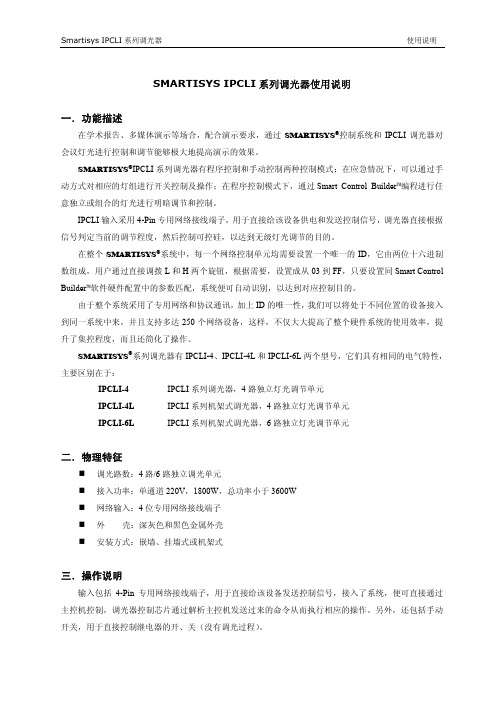
SMARTISYS IPCLI系列调光器使用说明一.功能描述在学术报告、多媒体演示等场合,配合演示要求,通过SMARTISYS®控制系统和IPCLI调光器对会议灯光进行控制和调节能够极大地提高演示的效果。
SMARTISYS®IPCLI系列调光器有程序控制和手动控制两种控制模式;在应急情况下,可以通过手动方式对相应的灯组进行开关控制及操作;在程序控制模式下,通过Smart Control Builder™编程进行任意独立或组合的灯光进行明暗调节和控制。
IPCLI输入采用4-Pin专用网络接线端子,用于直接给该设备供电和发送控制信号,调光器直接根据信号判定当前的调节程度,然后控制可控硅,以达到无级灯光调节的目的。
在整个SMARTISYS®系统中,每一个网络控制单元均需要设置一个唯一的ID,它由两位十六进制数组成,用户通过直接调拨L和H两个旋钮,根据需要,设置成从03到FF,只要设置同Smart Control Builder™软件硬件配置中的参数匹配,系统便可自动识别,以达到对应控制目的。
由于整个系统采用了专用网络和协议通讯,加上ID的唯一性,我们可以将处于不同位置的设备接入到同一系统中来,并且支持多达250个网络设备,这样,不仅大大提高了整个硬件系统的使用效率,提升了集控程度,而且还简化了操作。
SMARTISYS®系列调光器有IPCLI-4、IPCLI-4L和IPCLI-6L两个型号,它们具有相同的电气特性,主要区别在于:IPCLI-4 IPCLI系列调光器,4路独立灯光调节单元IPCLI-4L IPCLI系列机架式调光器,4路独立灯光调节单元IPCLI-6L IPCLI系列机架式调光器,6路独立灯光调节单元二.物理特征调光路数:4路/6路独立调光单元接入功率:单通道220V,1800W,总功率小于3600W网络输入:4位专用网络接线端子外壳:深灰色和黑色金属外壳安装方式:嵌墙、挂墙式或机架式三.操作说明输入包括4-Pin专用网络接线端子,用于直接给该设备发送控制信号,接入了系统,便可直接通过主控机控制,调光器控制芯片通过解析主控机发送过来的命令从而执行相应的操作。
信号发生器中文说明书,4-20ma,0-10V,0-2ma,PWM信号,正弦波信号,多功能信号发生器
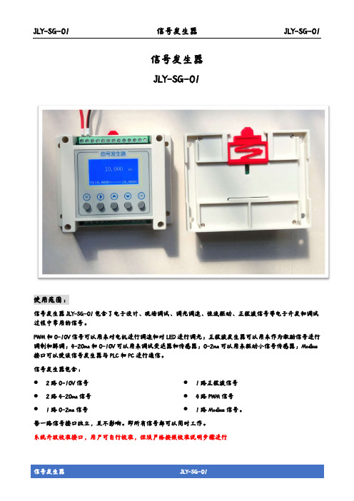
JLY-SG-01 信号发生器 JLY-SG-01信号发生器JLY-SG-01使用范围:信号发生器JLY-SG-01包含了电子设计、现场调试、调光调速、恒流驱动、正弦波信号等电子开发和调试过程中常用的信号。
PWM和0-10V信号可以用来对电机进行调速和对LED进行调光;正弦波发生器可以用来作为激励信号进行调制和解调;4-20ma和0-10V可以用来调试变送器和传感器;0-2ma可以用来驱动小信号传感器;Modbus 接口可以使该信号发生器与PLC和PC进行通信。
信号发生器包含:●2路0-10V信号 ●2路4-20ma信号 ●1路0-2ma信号 ●1路正弦波信号 ●4路PWM信号 ●1路Modbus信号。
每一路信号接口独立,互不影响。
即所有信号都可以同时工作。
系统开放校准接口,用户可自行校准,但须严格按照校准说明步骤进行JLY-SG-01信号发生器 JLY-SG-01JLY-SG-01主要特点:● 仪器小巧,告别笨重。
可手持、可桌面放置、可导轨安装亦可墙壁安装。
● 温度补偿,良好的稳定性,超高的精度 ● 工业化设计,响应速度快● 信号接口丰富且每路信号独立运行,互不干扰。
一机在手,调试无忧 ● 高亮度点阵屏,硅胶按键,手感颜值爆表 ● 模拟信号最低可以调整到0,使信号更完整技术指标:● 4-20ma:精度±0.5%,负载小于300Ω ● 0-2ma:精度±0.5%,负载小于3k Ω ● 0-10V: 精度±0.5%,负载大于5k Ω ● 正弦波信号:频率精度±0.5%,负载大于10K Ω,峰峰值:4.2V。
其频率可设置范围:50Hz ~ 999.999KHz ● PWM 信号:频率精度±0.5%,负载大于10K Ω,VH>2.4V,VL<0.6V,Vmax=5V。
其频率可设置范围:100Hz ~ 200KHz● 12~15VDC 供电,最大电流500ma ● 工作温度:0~50℃ ● 存储温度:-20~65℃ ● LCD12864显示屏,硅胶按键● 参数可通过MMI 按键设置亦可通过Modbus 设置 ● 预留用户校准接口,当仪表误差大时可自行校准(须严格按照校准操作章节进行操作)接线图:操作说明:●开机/关机操作关机状态下,短按“M”系统开机;开机状态下,长按“M”3s,待显示屏变暗后松开按键即可关机。
各种光源调光原理最新

光
调
)
光
调
光
调
前沿切相(FPC),可控硅调光
前沿调光就是采用可控硅电路, 从交流相位0 开始,输入电压斩 波,直到可控硅导通时,才有电 压输入。其原理是调节交流电每 个半波的导通角来改变正弦波形, 从而改变交流电流的有效值,以 此实现调光的目的。
前沿调光器具有调节精度高、效 率高、体积小、重量轻、容易远 距离操纵等优点,在市场上占主 导,多数厂家的产品都是这种类 型调光器。前沿相位控制调光器 一般使用可控硅作为开关器件, 所以又称为可控硅调光器。
LED灯调光原理示意图 ——后沿相位调光2
实物图片 后沿相位调光 后沿相位调光器
0-10V调光
0-10V 调光装置内有两条独立电路,一条为普通的电压电路,用于接 通或关断至照明设备的电源,另一条是低压电路,它提供参考电压, 告诉照明设备调光级别,0-10V 调光控制器之前常用在对荧光灯的调 光控制上,现在,因为在LED 驱动模块上加上了恒定电源,并且有专 门的控制线路,故0-10V 调光器同样可以支持大量的LED 照明灯。 但应用缺点也非常明显,低电压的控制信号需要额外增加一组线路, 这对施工的要求大大提高。(0-10V不是供电电压是控制电压,这种控 制方式属于模拟调光)
后沿切相控制调光器,采用场效应晶体管(FET)或绝缘栅双极型晶 体管(IGBT)设备制成。后沿切相调光器一般使用MOSFET 做为开 关器件,所以也称为MOSFET 调光器,俗称“MOS 管”。 MOSFET 是全控开关,既可以控制开,也可以控制关,故不存在可 控硅调光器不能完全关断的现象。另MOSFET 调光电路比可控硅更 适合容性负载调光,但因为成本偏高和调光电路相对复杂、不容易 做稳定等特点,使得MOS 管调光方式没有发展起来,可控硅调光器 仍占据了绝大部分的调光系统市场。
0-10V调光方案

上图是模拟电路的应用,R3,R4为2脚提供基准电压,通过调节可调电阻 VR1,可以调节0-10V输出电压,外围元件极少。 注意事项: 1.两个比较端的地(R2,R4的地)与4脚的地连线尽量接近和粗走线,保 持同一电位,以免影响输出线性。 2.如果需要增加负载过流保护,可在5脚输出串接一个自恢复保险。 3.要防止输出线反接,可在5脚与地之间反接一个SS14二极管做保护 4.12V输入电压必须稳定,否则会影响输出的稳定性。 5. 当输出调至最低0.6V时,处于失调区,在重载的时候,根据负载 特性不同(输出型或吸入型),这个电压会有约+-0.2V的偏差, 当输出高于0.8V时,带载能力正常,受负载影响很小。 6.IC最大输出电压为VCC-1V,当VCC=12V时,最大输出电压约11V
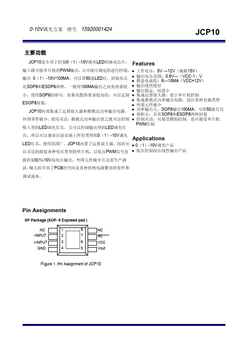
LED灯具,使用范围广,JCP10内置了运算放大器,因此可 ● 0(1)-10V调光产品 以灵活的接驳各种电压类型的单片机,以低压PWM信号直 ● 低压控制高压线性输出产品 接控制0(1)-10V高电压输出,外围元件极少且无需生产调 试, 极大的节省了PCB的空间及各种传统电路繁杂的零件和 调试成本。
输入既可接单片机的PWM输出, 又可接可调电阻进行控制, ● ● 输出 0(1)-10V/100MA,可以带50盏LED灯,封装形式 ● 有SOP8和ESOP8两种,一般用100MA输出之内发热量较 ● ● 小,使用SOP8的即可,如果对散热要求较高的,可以定制 ● ● ESOP8封装。 ● JCP10内部集成了运算放大器和推挽式功率输出电路, ● ● 外围零件极少,使用灵活,推挽式功率输出使之既可以控制 ● 吸入型的LED调光灯具,又可以控制输出型的LED调光灯 具,所以可以兼容目前市场上所有类型的0(1)-10V调光
0-10V调光
吸入型的LED调光灯具,又可以控制输出型的有类型的0(1)-10V调光 Applications
LED灯具,使用范围广,JCP10内置了运算放大器,因此可 ● 0(1)-10V调光产品 以灵活的接驳各种电压类型的单片机,以低压PWM信号直 ● 低压控制高压线性输出产品
接控制0(1)-10V高电压输出,外围元件极少且无需生产调
试,极大的节省了PCB的空间及各种传统电路繁杂的零件和
调试成本。
Pin Assignments
SP Package (SOP- 8 Exposed pad )
NC
1
-INPUT
2
+INPUT
3
GND
4
8
NC
7
NC
6
VCC
5
Vout
Figure 1. Pin Assignment of JCP10
1.55
0.31
0.51
4.80
5.00
1.82
3.35
3.80
4.00
1.82
2.41
1.20
1.34
5.80
6.20
0.40
1.27
Note:Followed From JEDEC MO-012-E.
Carrier dimensions
2.如果需要增加负载过流保护,可在5脚输出串接一个自恢复保险。 3.要防止输出线反接,可在5脚与地之间反接一个SS14二极管做保护 4.12V输入电压必须稳定,否则会影响输出的稳定性。 5. 当输出调至最低0.6V时,处于失调区,在重载的时候,根据负载
特性不同(输出型或吸入型),这个电压会有约+-0.2V的偏差, 当输出高于0.8V时,带载能力正常,受负载影响很小。 6.IC最大输出电压为VCC-1V,当VCC=12V时,最大输出电压约11V
级德 RF 0-10V分光光源控制墙面开关说明书
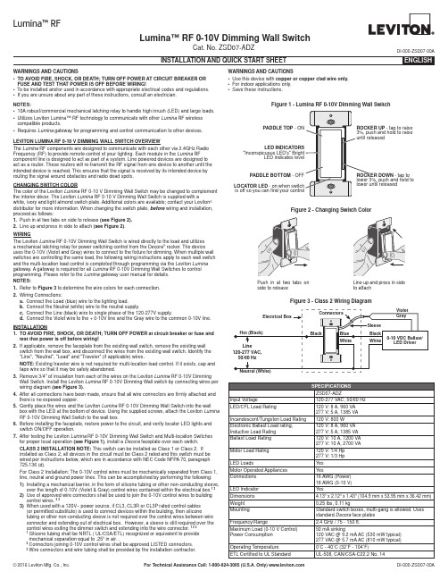
Lumina™ RF 0-10V Dimming Wall SwitchCat. No. ZSD07-ADZDI-000-ZSD07-00ALEVITON LUMINA RF 0-10 V DIMMING WALL SWITCH OVERVIEWThe Lumina RF components are designed to communicate with each other via 2.4GHz Radio Frequency (RF) to provide remote control of your lighting. Each module in the Lumina RF component line is designed to act as part of a system. Line powered devices are designed to act as a router. These routers will re-transmit the RF signal from one device to another until the intended device is reached. This ensures that the signal is received by its intended device by routing the signal around obstacles and radio dead spots.CHANGING SWITCH COLORThe color of the Leviton Lumina RF 0-10 V Dimming Wall Switch may be changed to complement the interior décor. The Leviton Lumina RF 0-10 V Dimming Wall Switch is supplied with awhite, ivory and light almond switch plate. Additional colors are available; contact your Leviton ® distributor for more information. When changing the switch plate, before wiring and installation, proceed as follows:1. P ush in at two tabs on side to release (see Figure 2).2. L ine up and press in side to attach (see Figure 2).WIRINGThe Leviton Lumina RF 0-10V Dimming Wall Switch is wired directly to the load and utilizes a mechanical latching relay for power switching control from the Decora ® rocker. The device uses the 0-10V (Violet and Gray) wires to connect to the fixture for dimming. When multiple wall switches are controlling the same load, the following wiring instructions apply to each wall switch and the multi-location load control is completed through programming via the Leviton Lumina gateway. A gateway is required for all Lumina RF 0-10V Dimming Wall Switches to control programming. Please refer to the Lumina gateway user manual for details.NOTES:1. R efer to Figure 3 to determine the wire colors for each connection.2. W iring Connections:a. C onnect the Load (blue) wire to the lighting load.b. C onnect the Neutral (white) wire to the neutral supply.c. C onnect the Line (black) wire to single phase of the 120-277V supply.d. C onnect the Violet wire to the + 0-10V line and the Gray wire to the common 0-10V line.INSTALLATION 1. T O AVOID FIRE, SHOCK, OR DEATH; TURN OFF POWER at circuit breaker or fuse and test that power is off before wiring!2. I f applicable, remove the faceplate from the existing wall switch, remove the existing wall switch from the wall box, and disconnect the wires from the existing wall switch. Identify the "Line", "Neutral", "Load" and "Traveler" (if applicable) wires.NOTE: Existing traveler wire is not required for multi-location load control. If it exists, cap and tape wire so that it may be safely abandoned.3. R emove 3/4" of insulation from each of the wires on the Leviton Lumina RF 0-10V Dimming Wall Switch. Install the Leviton Lumina RF 0-10V Dimming Wall switch by connecting wires per wiring diagram (see Figure 3).4. A fter all connections have been made, ensure that all wire connectors are firmly attached and there is no exposed copper.5. G ently place the wires and the Leviton Lumina RF 0-10V Dimming Wall Switch into the wall box with the LED at the bottom of device. Using the supplied screws, attach the Leviton Lumina RF 0-10V Dimming Wall Switch to the wall box.6. B efore installing the faceplate, restore power to the circuit, and verify locator LED lights and switch ON/OFF operation.7. A fter testing the Leviton Lumina RF 0-10V Dimming Wall Switch and Multi-location Switches for proper local operation (see Figure 1), install a Decora faceplate over each switch.CLASS 2 INSTALLATION NOTE: This switch can be installed as Class 1 or Class 2. If installed as Class 2, all devices in the circuit must be Class 2 rated and this switch must be wired per instructions below, which are in accordance with NEC Code NFPA 70, paragraph 725.136 (d).For Class 2 Installation: The 0-10V control wires must be mechanically separated from Class 1, line, neutral and ground power lines. This can be accomplished by performing the following:1) I nstalling a mechanical barrier, in the form of silicone tubing or other non-conducting sleeve, over the length of 0-10V (Violet & Gray) control wires contained within the electrical box.1 32) U se of approved wire connectors shall be used to join the 0-10V control wires to building control wires. 2 33) W hen used with a 120V~ power source, if CL3, CL3R or CL3P rated control cables (or permitted substitute) is used to connect devices within the building, then siliconetubing or other non-conducting sleeve is not required over the control wires between wire connector and extending out of electrical box. However, a sleeve is still required over the control wires exiting the dimmer switch and extending into the wire connector. 1 2 31 S ilicone tubing shall be NRTL ( UL/CSA/ETL) recognized or equivalent to provide mechanical separation equal to .25” in air. .2 C onnectors joining 0-10V control wires shall be approved LISTED connectors.3 W ire connectors and wire tubing shall be provided by the installation contractor.NOTES:• 10A robust/commercial mechanical latching relay to handle high inrush (LED) and large loads.• U tilizes Leviton Lumina™ RF technology to communicate with other Lumina RF wireless compatible products.• R equires Lumina gateway for programming and control communication to other devices.WARNINGS AND CAUTIONS• T O AVOID FIRE, SHOCK, OR DEATH; TURN OFF POWER AT CIRCUIT BREAKER OR FUSE AND TEST THAT POWER IS OFF BEFORE WIRING!• T o be installed and/or used in accordance with appropriate electrical codes and regulations.• I f you are unsure about any part of these instructions, consult an electrician.WARNINGS AND CAUTIONS• U se this device with copper or copper clad wire only.• F or indoor applications only.• S ave these instructions.Figure 3 - Class 2 Wiring DiagramLumina™ RFFigure 1 - Lumina RF 0-10V Dimming Wall SwitchLOCATOR LEDPADDLE BOTTOM - tap to - tap to raisePADDLE TOP Figure 2 - Changing Switch ColorFOR CANADA ONLYFor warranty information and/or product returns, residents of Canada should contact Leviton in writing at Leviton Manufacturing of Canada Ltd to the attention of the Quality Assurance Department, 165 Hymus Blvd, Pointe-Claire (Quebec), Canada H9R 1E9 or by telephone at 1 800 405-5320.FCC COMPLIANCE STATEMENT:Contains FCC ID: W7Z-ZICM357SP0The enclosed device complies with Part 15 of the FCC Rules. Operation is subject to the following two conditions:(i.) This device may not cause harmful interference (ii.) This device must accept any interference received, including interference that may cause undesired operation. Any changes or modifications not expressly approved by Leviton could void the user’s authority to operate this equipment. This equipment has been tested and found to comply with the limits for a Class B digital device, pursuant to part 15 of the FCC Rules. These limits are designed to provide reasonable protection against harmful interference in a residential installation. This equipment generates uses and can radiate radio frequency energy and, if not installed and used in accordance with the instructions, may cause harmful interference to radio communications. However, there is no guarantee that interference will not occur in a particular installation. If this equipment does cause harmful interference to radio or television reception, which can be determined by turning the equipment off and on, the user is encouraged to try to correct the interference by one or more of the following measures:• Reorient or relocate the receiving antenna.• Increase the separation between the equipment and receiver.• Connect the equipment into an outlet on a circuit different from that to which the receiver is connected.• Consult the dealer or an experienced radio/TV technician for help.INDUSTRY CANADA COMPLIANCE STATEMENT:Contains IC: 8254A-ZICM357SP0.This device complies with Industry Canada license-exempt RSS standard(s). Operation is subject to the following two conditions: (1) this device may not cause interference, and (2) this device must accept any interference, including interference that may cause undesired operation of the device. IMPORTANT! Any changes or modifications not expressly approved by the party responsible for compliance could void the user’s authority to operate this equipment. This Class B digital apparatus complies with Canadian ICES-003.LEVITON LIMITED WARRANTYLeviton warrants to the original consumer purchaser and not for the benefit of anyone else that products manufactured by Leviton under the Leviton brand name (“Product”) will be free from defects in material and workmanship for the time periods indicated below, whichever is shorter: • OmniPro II and Lumina Pro : three (3) years from installation or 42 months from manufacture date. • Omni LTe, Omni IIe, and Lumina : two (2) years from installation or 30 months from manufacture date. • BitWise Controllers, Accessories : two (2) years from installation or 30 months from manufacture date. • Lumina Gateway Controllers : two (2) years from installation or 30 months from manufacture date. • Thermostats, Accessories : two (2) years from installation or 30 months from manufacture date. • Batteries : Rechargeable batteries in products are warranted for ninety (90) days from date of purchase. Note : Primary (non-rechargeable) batteries shipped in products are not warranted. Products with Windows ® Operating Systems : During the warranty period, Leviton will restore corrupted operating systems to factory default at no charge, provided that the product has been used as originally intended. Installation of non-Leviton software or modification of the operating system voids this warranty. Leviton’s obligation under this Limited Warranty is limited to the repair or replacement, at Leviton’s option, of Product that fails due to defect in material or workmanship. Leviton reserves the right to replace product under this Limited Warranty with new or remanufactured product. Leviton will not be responsible for labor costs of removal or reinstallation of Product . The repaired or replaced product is then warranted under the terms of this Limited Warranty for the remainder of the Limited Warranty time period or ninety (90) days, whichever is longer. This Limited Warranty does not cover PC-based software products. Leviton is not responsible for conditions or applications beyond Leviton’s control. Leviton is not responsible for issues related to improper installation, including failure to follow written Installation and operation instructions, normal wear and tear, catastrophe, fault or negligence of the user or other problems external to the Product . To view complete warranty and instructions for returning product, please visit us at .SETUP MODE FOR CONTROLS COMMUNICATIONConfigure the Leviton Lumina RF 0-10V Dimming Wall Switch using a Lumina gateway. Visit the Leviton Cloud Service at for gateway installation software. NOTE: The device must be in mode 1, enrollment while the Lumina gateway is searching for new devices to Enroll.NOTE: The pairing mode happens very quickly once it scans network and finds another device in identify mode. Devices need to be enrolled in network for 3-way pairing to work. Pairing and Identify needs to be done on both devices for full 3-way control. The maximum amount of devices that can be paired is 8 devices.SWITCH OPERATIONLocal Rocker Switch OperationThe Leviton Lumina RF 0-10V Dimming Wall Switch has a rocker that can be used to control the load (see Figure 1).LED IndicatorThe Leviton Lumina RF 0-10V Dimming Wall Switch comes equipped with a locator LED indicator that is normally lit to green when the load is OFF. The locator LED is OFF when the load is ON.Dimming LED IndicatorThe Leviton Lumina RF 0-10V Dimming Wall Switch also has a dimming indicator on the left side of the switch to display the current dimming level via single bright LED - the remaining LED’s will be lit at a dimmer level to display range of dimming. The bright LED will move up or down the dimming indicator based on user presses to the Dim/Bright rocker.。
ABB 荧光灯调光器操作手册
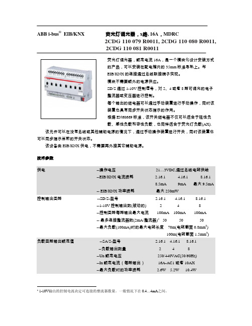
2CDG 110 079 R0011, 2CDG 110 080 R0011,2CDG 110 081 R0011荧光灯调光器,额定电流16A,是一个模块化设计安装方式的产品,可以安装在配电箱内的35mm标准导轨上。
与EIB/KNX的连接通过总线联接端子实现。
模块不需要额外的电源供应。
SD/S通过1-10V控制信号,对2、4或者8路可调光的电子整流器或变压器进行控制。
每个输出的继电器可以通过手动装置进行手动操作,同时该装置也具有同步开关状态指示的作用。
根据EN60669标准,该开关继电器不仅可以适合于阻性负载、感性负载和容性负载,也同样适合于荧光灯负载(AX).该元件可以在没有总线或其他辅助电源的情况下,通过手动操作装置进行开关,同时该装置也可以同步指示当前的开关状态。
该设备由EIB/KNX供电,不需要再外接其它辅助电源。
技术参数供电 --操作电压 21…3VDC,通过总线电缆供给--EIB/KNX 电流损耗 2.16.1 4.16.1 8.16.18.5mA 9mA 最大9.5mA-- EIB/KNX 功率损耗最大250mW控制输出回路 --SD/S-型号 2.16.1 4.16.1 8.16.1--1-10V控制输出数(被动的) 2 4 8--控制回路每路输出最大电流 100mA 100mA 100mA-- 最多连接整流器数(2mA/整流器)1 50 50 50--最大负载(100mA)时的最大电缆长度 70m(电缆截面0.8mm2)100m(电缆截面1.5mm2)负载回路输出额定值 --SA/S-型号 2.16.1 4.16.1 8.16.1--负载输出数量 2 4 8--Un额定电压 250/440VAC(50/60Hz)--In额定电流(每路输出) 16A-AC1 或者10AX--最大负载时的功率损耗 2.6W 5.2W 10.4W1 1-10V输出的控制电流决定可连接的整流器数量。
一般情况下在0.4…4mA之间。
zigbee无线智能调光器0-10V

ZigBee无线0-10V智能调光控制器说明1.发射器需要具备发射开或关以及控制接收器调光的功能(是0-10V调光)【Wulian】可以实现2.发射器上的开关按钮只有一个,类似居家的墙壁开关,跷跷板。
上面是开兼调光到亮的功能,按下面是调光暗,直到关闭的功能。
【Wulian】按钮有两个,可以实现3.如果两个发射器安装位置近,注意不能彼此收到干扰。
有时是两个发射器装在一起甚至三个以上,这样可以控制不同的灯具。
【Wulian】可以实现。
4.一个发射器可以同时控制多个接收器,即多个负载同时开启或关闭,以及同时调光。
【Wulian】最多几个?5.发射器一定要是低功耗,要求一颗纽扣电池可以维持一年左右。
注意每天开关次数是不定的。
但应该不会太频繁。
【Wulian】需要根据使用频率估算。
目前设计2颗纽扣电池仓,发货配2颗纽扣电池,日常使用用1~2年。
6.接收器是安装在灯具上,基本每个灯具会安装一个,可能多个灯具安装一个【Wulian】多个灯具在一起就是同样的反应步调。
7.接收器输入是120-277全电压,通过继电器输出也是120-277电压给LED灯具的电源(发射型号控制继电器开或关),同时还要输出两根线用于连接LED 电源上的调光控制线(0-10V调光)。
【Wulian】已经有0-10V调光输出了,再通过继电器输出120~270V用哪里?接收器要小型化,因为是安装在灯具里面。
因为灯具外壳是金属的。
铝或铁是否会影响接收距离,而且是安装在天花板上的。
【Wulian】灯具要透光,应该是有非金属面罩的。
一般情况问题不大。
金属都有屏蔽信号的作用,安装使用时要避免。
而且要和光源隔离,热量较大。
8.接受距离一般是在多少米范围,是否可以增加接收距离【Wulian】室内50米9.目前不用联网操作,基本的一对一或一对多。
但未来肯定是需要联网的,知道需要增加其他装置,但希望能将这个功能事先预留。
【Wulian】可以。
联网只用增加网关即可,就可以实现APP控制。
LF-1010中文说明书

LED舞台地板灯说明书LF-1010 使用本灯具前,敬请通读本手册1、开箱检查首先感谢您选择了本公司的产品,请仔细完整地阅读这份使用说明手册,并妥善保管,以便使用时参考。
本使用说明书中包含有关本产品的安装及使用方面的重要信息,安装及使用时请严格遵守相关说明。
本地砖灯采用新型高强度有机玻璃面盖制造而成,造型美观、流畅,充分体现了现代灯具产品的特点。
产品严格按CE标准进行设计生产,完全符合国际标准DMX512协议,既可单台控制,也可以互相联控使用,适用于T台演出、舞厅、演艺厅及迪高等场所使用。
在收到产品时,请小心取放;检查产品是否有因运输而可能造成的损坏,并检查以下配件:电源线--------------1条螺丝-----------------4枚说明书--------------1本连接件-------------- 1个保修卡--------------1张合格证-------------- 1张2、安全说明所有与此设备安装与维护有关的人员必须:-具有技术员资格-遵循此说明书的要求注意:防水、防潮,打开机箱前注意断开主电源!此设备离厂一切正常,为确保产品的正常使用和安全操作,用户必须遵守以下安全规定和注意事项:♦生产厂家将不对任何未按此说明书正常操作使用和未经许可则私自更改设备所引起的任何事故和损失负责。
♦对任何随意更改说明书说明所引起的设备故障将不在保修范围内。
♦不要将电源线与其它电线连接在一起!特别注意电源电压与主机的标示电压相符!确保有效电压未超过后部窗口上的标识电压。
♦保证电源插头插入电源座,确保连接设备到主电源前电源开关高为OFF/关的位置。
♦确保电源线不要被折断或被锋利物割破或损坏,定时检查设备及电源线。
♦当设备停止使用或在清洁前请断开主电源,拉动电源线时请断开插头拉动。
♦此设备的保护级别为I级,所以请把黄/绿线接地(接地电阻<0.5Ω)。
♦线路连接、维修及服务都必须由专门的技术人员来进行。
三路0-10伏特调光器与整滑控制设计说明书

DescriptionSingle Pole & 3-Way0-10 Volt Dimming Control with Integrated ON/OFF SwitchDesign features•Preset feature allows user to return to previous light level when turning lights ON• Integrated full-slide control for easy, precise operation • Can be wired as Single Pole or 3-Way• Neutral is not required for installation of device• Adjustable high-level trim setting for optimal lamp compatibility • Faceplate is removable to allow for color changes • Each package includes 3 colors • Electrostatic discharge protection•Compatible with any decorator wallplate or screwless decorator wallplate•Compatible with dimmable LED and Fluorescent 0-10 Volt ballasts•California Title 20 compliantDF10PProject Name:Prepared By:Project Number:Date:Catalog Number:Type:Decorator 0-10 Volt DimmerT able 1. D ecorator Dimmers, Back & Side WireCatalog No.CompatibleLamp TypesDescriptionRating Watt V/ACColor SuffixDF10P__Dimmable LED/FLR 0-10V BallastsSlide Dimmer, Single-Pole/3-Way Preset 1200120C1, C2, C4, C51660277DCK1____Color ChangeFaceplate for DF10P____A, B, BK, GY, LA, V, WCompliances, specifications and availability are subject to change without notice.2EATON /wiringdevicesTechnical DataEffective March 2018Decorator 0-10 Volt DimmerCatalog No.DF10P, DCK1 SeriesDevice Type Decorator Slide Dimmers, AL Series Wiring TypeBack & side wire terminals + 10V wire leads Testing & Code Compliance • cULus Listed to UL1472, file no. E47967• NOM Certified• California Title 20 compliantEnvironmental Specifications Flammability: Meets UL 94 requirements; V2 rated Temperature Rating: -20ºC to 70ºC (-4°F to 158°F)Electrical SpecificationsRating: 120V/AC, 60 Hz; 277V/AC, 60 HzLight Intensity Control: Full-range, continuously variable dimming Dimming Performance: 0-10V DimmingSurge Protection: Meets ANSI/IEEE Std. C62.41-1980, tested to withstand volt-age surges up to 6000V and current surges of up to 200A without damagePower-failure Memory: Light returns to same level prior to power interruption Lamp Ratings - Switch Relay: 1200W @ 120V/AC, 1660W @ 277V/AC Dimming Control Power: 0-10V/DC: 200 mA Mechanical SpecificationsWiring Types: Single Pole & 3-WayVoltage Ratings: Permanently marked on deviceEaton’s Decorator 0-10V Dimmer provides full-range classic linear-slide dimming for 0-10 Volt compatible dimmable light sources. These units are ideal for residential and light commercial applications and are compatible with Eaton’s Decorator style devices and wallplates. Units feature a preset “ON/OFF” switch that automatically returns controlled light(s) to a preset level without disturbing the brightness level. The device is designed for both Single Pole (one location) and 3-Way (multi-location) applications. Not recommended for applications involving frequent use of ammonia based cleaners. Catalog No.DF10P, DCK1 SeriesTop Housing Polycarbonate Bottom Housing Polycarbonate StrapAluminum Form Factor Decorator FinishGlossT able 2. SpecificationsApplicationsT able 3. MaterialsProject Name:Prepared By:Project Number:Date:Catalog Number:Type:T able 4. Color Ordering InformationFor ordering devices, include Cat. No. followed by the color code: A (Almond), BK (Black), GY (Gray) LA (Light Almond), V (Ivory), W (White)Compliances, specifications and availability are subject to change without notice.Color Kit Color Combinations and Ordering Suffixes (for select models):C1 Color KitA (Almond), W (White), V (Ivory)C2 Color KitLA (Light Almond), W (White),V (Ivory)C4 Color KitBK (Black), W (White), V (Ivory)C5 Color KitBK (Black), W (White), GY (Gray)Technical DataEffective March 2018Decorator 0-10 Volt DimmerProject Name:Prepared By:Project Number:Date:Catalog Number:Type:Single-Pole Wiring Diagram 3-Way Wiring DiagramWiring DiagramsCertifications & CompliancesKEY:cULusNOMTitle 20 compliantDCK1•••Compliances, specifications and availability are subject to change without notice.Electrical Sector 203 Cooper CirclePeachtree City, GA 30269United States /wiringdevicesElectrical Sector Canada Operations 5925 McLaughlin RoadMississauga, Ontario, L5R 1B8CanadaEatonCanada.ca/wiringdevicesElectrical Sector Mexico Operations Carr. Tlalnepantla -Cuautitlan Km 17.8 s/n Col. Villa Jardin esq.Cerrada 8 de MayoCuautitlan, Mexico CP 54800Mexico Eaton.mx/wiringdevicesEaton is a registered trademark. All other trademarks are property of their respective owners.Eaton1000 Eaton Boulevard Cleveland, OH 44122United States © 2018 EatonAll Rights Reserved Printed in USAPublication No. TD610067EN (REV . 1)March 2018Product DimensionsFigure 1. DF10P Line Art with Dimensions。
0-10v调光 施工要求
0-10v调光的施工要求包括以下几点:
1.遵循安全、环保、节能的原则。
施工人员应具备专业的技术知识,遵
守相关的法律法规。
在工程施工前,要进行充分的规划和设计,确保照明设施的布局和样式与城市的整体风格相协调。
2.选购品质好、符合标准要求的产品,以保证设施的使用寿命和整体效
果。
3.根据实际情况对光线亮度进行调整。
不同的地区和场所,对于照明的
要求并不完全相同。
在商业区和人流密集的地方,需要较亮的照明来确保人们的安全和便利。
而在居民区和公园等需要较为舒适的环境,可以适当降低照明亮度,以减少光污染对居民的影响。
此外,城市照明工程的亮度调整,还需要综合考虑居民的反馈和专业评估。
4.设备间距有一定的要求,必须满足设备的通风和散热要求,施工接线
方便。
为满足这两个要求,上下硅箱间距不小于300mm。
灰尘会影响设备的散热。
由于环境潮湿,设备控制失效甚至损坏。
因此,必须定期除尘,以确保设备的适当工作环境。
5.设备会发热,安装设备的地方必须通风。
严禁堵塞设备的通风和散热
孔。
未明确标明室外使用产品(如室外照明传感器),均为室内使用。
如需室外使用,应采取防水防尘措施。
6.不同的设备有不同的工作温度和湿度要求,如设备的工作温度一般为
0-45℃,工作湿度一般为0-95%,无霜冻。
因此需要根据具体设备的要求施工和使用。
以上就是0-10v调光施工的主要要求,仅供参考,建议咨询专业施工人员获取更全面和准确的信息。
0-10v调光器原理
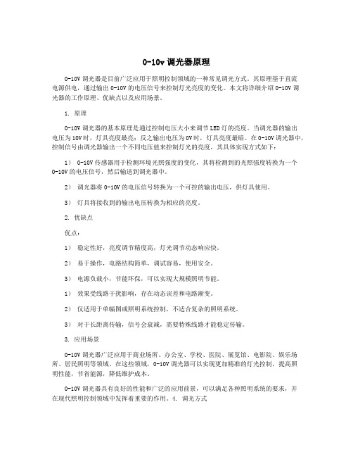
0-10v调光器原理0-10V调光器是目前广泛应用于照明控制领域的一种常见调光方式。
其原理基于直流电源供电,通过输出0-10V的电压信号来控制灯光亮度的变化。
本文将详细介绍0-10V调光器的工作原理、优缺点以及应用场景。
1. 原理0-10V调光器的基本原理是通过控制电压大小来调节LED灯的亮度。
当调光器的输出电压为10V时,灯具亮度最亮;反之输出电压为0V时,灯具亮度最暗。
在0-10V调光器中,控制信号由调光器输出一个不同电压值来控制灯光的亮度,其具体实现方式如下:1) 0-10V传感器用于检测环境光照强度的变化,其将检测到的光照强度转换为一个0-10V的电压信号,然后输送到调光器中。
2)调光器将0-10V的电压信号转换为一个可控的输出电压,供灯具使用。
3)灯具将接收到的输出电压转换为相应的亮度。
2. 优缺点优点:1)稳定性好,亮度调节精度高,灯光调节动态响应快。
2)易于操作,电路结构简单,调试容易,使用安全。
3)电源负载小,节能环保,可以实现大规模照明节能。
1)效果受线路干扰影响,存在动态误差和电路渐变。
2)仅适用于单幅图或照明系统控制,不适合复杂的照明系统。
3)对于长距离传输,信号会衰减,需要特殊线路才能稳定传输。
3. 应用场景0-10V调光器广泛应用于商业场所、办公室、学校、医院、展览馆、电影院、娱乐场所、居民照明等领域。
在这些领域,0-10V调光器可以实现更加精准的灯光控制,提高照明性能,节省能源,降低维护成本。
0-10V调光器具有良好的性能和广泛的应用前景,可以满足各种照明系统的要求,并在现代照明控制领域中发挥着重要的作用。
4. 调光方式0-10V调光器有两种基本的工作方式:模拟电压调光和数字信号调光。
模拟电压调光是通过控制一个模拟电压来调节灯的亮度,而数字信号调光则是通过控制数字信号的频率和占空比来实现调光。
模拟电压调光具有使用方便、调节精度高、亮度连续可调等优势,适用于小范围的调光场合。
0-10调光器中文说明书
带开关,开关最大电流1A,标准的接线端口
符合国标86面板,尺寸为86*86*55mm
连线方便简单,旋转即可无级调光,不频闪.
产品参数:
型号:YX-219
输入电压:110-10V
带开关:YES
开关电流:1Amax
输入电压110220v5060hz输出电压直流010v与调光电子镇流器led可调光驱动器配套带开关开关最大电流1a标准的接线端口符合国标86面板尺寸为868655mm连线方便简单旋转即可无级调光不频闪
需要请加,扣:132_213_0074
功能特点:
输入电压110-220V,50/60HZ
输出电压直流0-10V
工作温度:0-60°C
外壳尺寸:86*86*55mm
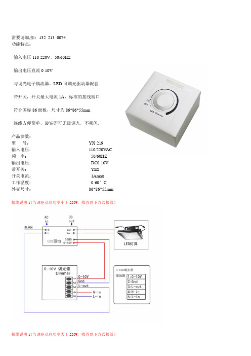
接线说明1(当调驱动总功率小于220W,推荐以下方式接线)
接线说明1(当调驱动总功率大于220W,推荐以下方式接线)