卡洛斯精密空调操作手册
空调的使用说明书
空调的使用说明书空调的正确使用方法空调的正确使用方法1、首次使用空调时应详细阅读《使用说明书》,并按照上面介绍的方法进行操作。
2、设定合适的温度:一般设定在26℃-27℃的范围对人的感觉比较适合,由于现在许多空调都具有经济睡眠功能,所以睡觉前最好启动该功能,以保证睡着和醒来时不会觉得太凉。
3、选择合适的出风口角度,尽量避免对准人体,特别是人在睡眠中直接吹冷风容易得病。
目前空调器的双向科学送风功能一般都可以解决这一问题,可以自动设定制冷时角度朝上,制热时角度朝下。
4、有效使用定时器。
睡眠及外出时,请利用定时器。
使其仅在必要时间内运转,以便省电。
5、经常清洁空气过滤网,过滤往被堵塞会降低运转性能,从而导致电费增加,应半月左右清扫一次。
6、不要让阳光和热风进入房间,在冷气开放时最好用窗帘或百叶窗遮挡阳光;同时开启空调后尽量少开门窗,减少冷量的损耗,节约用电。
7、切物有物体挡住市内外的进出风口,否则会降低制冷制热效果,浪费电力,严重的回导致空调器无法正常工作。
8、仅在必要时候开启空调器,既可以使空调得到有效利用又可以节约用电。
9、在开机时首先将制冷或制热开在强劲档,如果您的空调没有强劲功能,那么最好开在高风档,当温度适宜时再将设置改到中档或抵挡,减少能耗,减低噪音。
10、空调器停、开操作时间,应间隔3分钟以上,不能连续停、开。
11、开空调时室内要保持一定的新鲜空气,可以避免人在空调房间患“空调病”。
如果您的空调没有换气功能,呢么可以将门窗开个小缝,让新风从门窗缝自然渗入。
12、室内空调运转时,请勿将手指或木棍等物品插入空气的进出风口,因为空调内的风扇在高速运转,有可能引起伤害事故。
13、空调器应该使用专用的电源插座,请勿将电源连接到中间插座上,禁止使用加长线或与其他电器功用,有可能引起触电、发热或火灾事故。
14、请勿损伤或改造电源线,有可能引起触电、发热或火灾事故。
15、请按照说明书介绍的方法正确开关机、勿采用插入或拔出电源线的方法来起动或停止空调机的运转,这样有可能会引起触电或火灾事故。
精密空调系统安装施工应用手册

精密空调系统安装施工应用手册目录(一)勘测前准备: (1)(二)勘测: (1)(三)施工现场: (1)(四)工具及材料准备: (1)(五)工程材料: (2)(六)工程材料的外观检验及规格: (2)(七)开箱验货: (6)(八)机房空调设备安装: (7)(九)现场安装施工原则: (8)(十)安全作业原则: (9)(十一)设备安装原则: (11)(十二)底座的安装制作: (15)(十三)冷凝器安装原则: (16)(十四)电气安装原则: (17)(十五)冷凝水泵的安装(备选件) (17)(十六)冷媒管道的安装: (19)(十七)冷媒铜管钎焊: (22)(十八)压缩机控制阀操作: (25)(十九)系统气密检漏: (26)(二十)给、排水管道的连接: (27)(二十一)风管的安装: (30)(二十二)导流片安装要求: (32)(二十三)柔性管安装要求: (32)(二十四)止回阀安装要求: (33)(二十五)绝热层与保温钉安装要求: (33)(二十六)风管支、吊架安装要求: (33)(二十七)施工工艺基础知识: (34)(二十八)机械装联工艺: (34)(二十九)成组螺栓的安装: (35)(三十)接地端子的安装: (35)(三十一)电气装联工艺: (38)(三十二)接线原则: (38)(三十三)接线要求: (40)(一)勘测前准备:1、到现场勘测的工程师,必须清楚明白销售人员与用户所签订意向合同的内容。
2、室内外机组型号、数量,有无主备关系;备选项目;其他附带条款、事项。
3、工程师依据意向合同内容,根据现场勘测结果,初步核实机组的配置是否正确,合同有无遗漏事项。
4、带上勘测工具。
(二)勘测:1、设备安装前要对将要安装设备的环境作施工勘查,勘测过程中要认真、仔细(详细的勘测内容及方法,见附录一:勘测报告指导书)。
主要检查内容为:2、设备搬运环境:勘查空调设备搬运到安装现场环境,确定搬运类型,否则将影响到搬运成本。
卡洛斯精密空调PCO3控制器操作手册
卡洛斯精密机房空调PCO3机房空调控制器操作手册总体特性16位微处理器,14MHZ主频,内部寄存器和32位运行,512字节内部RAM;每一应用程序可使用多达6兆字节闪烁存储器;256K字节静态存储器,可按要求扩展到1M字节;一个RS485串行通讯口,用于组成局域网PLAN,并可实现主备切换与轮值功能;用PCO3004850(是PCO3电子控制器的一项选件)可连接至RS485集中监控网络;配有可更换锂电池的实时钟;56字节电池后备RAM;PLAN用的地址设定功能及状态指示灯LED;塑料外壳,安装于DIN制Ω型导轨;24Vac/Vdc供电;电话线接口,用于连接手操器;电话线接口,用于连接打印机;LED电源指示;多种语言;用户手操器允许显示机组的工作的情况并能修改参数。
另外,手操器也能与主控制板断开,机组仍能正常运行。
也就是说,当机组正常运行后,手操器的存在并无严格的限制。
方便的程序更新,可以通过网络计算机下载到控制器上,保证用户所使用的程序最新;可以通过发送手机短消息,远程遥控机组开/关机(有权限限制)。
通过GETWAY可以方便地将控制系统接入当今流行的楼宇控制系统,兼容各种开放的楼宇控制协议;12个光电隔离的开关量输入,24Vac 50/60Hz 或24Vdc;2个光电隔离的开关量输入,24Vac /Vdc 或230Vac (50/60Hz);13个开关量输出继电器(其中三个为常开常闭切换型);2个模拟量输入,可选择NTC、PT1000或开关型;6个模拟量输入,可选择NTC、0~1V、0~10V、0~20mA或4~20mA;4个模拟量输出,0~10V。
硬件结构PCO3 控制器,配置16位微处理器以运行调节程序,配置输入输出端子以连接被控设备(例如阀、压缩机、风机等)。
程序及参数集永久性地存在闪烁存储器中,无需后备电池,停电亦不会导致数据的丢失。
PCO3还可以接入由多至32台PCO3及手操器组成的局域网pLAN中,每一主板都可以高传输速率交换信息(根据应用程序,可以是开关式的或模拟式的变量)。
暖通空调知识:精密空调活塞式制冷压缩机的安全运行操作[工程类精品文档]
![暖通空调知识:精密空调活塞式制冷压缩机的安全运行操作[工程类精品文档]](https://img.taocdn.com/s3/m/6abcaa6531b765ce050814cc.png)
暖通空调知识:精密空调活塞式制冷压缩机的安全运行操作[工程类精品文档]本文内容极具参考价值,如若有用,请打赏支持,谢谢!精密空调制冷系统各设备的正确操作,是制冷系统安全经济运行的重要保证,同时对延长精密空调设备的使用寿命、降低能耗有着重要的意义。
精密空调开机前的准备工作1.运行记录的查看对所有不同类型的精密空调制冷压缩机,在运行前都应査看其运行记录,了解上次停机的原因和时间,若因故障停机,必须检查故障是否安全排除,再查看库温和热负荷,确定启动台数。
2.检查精密空调压缩机(1)精密空调压缩机四周应无杂物、外露运动部件,应有安全保护罩。
(2)精密空调曲轴箱油压应在0.2MPa以下,若高于0.2MPa,应先降压,如经常如此,应查明原因。
曲轴箱油位在只有一个视孔时须在它的1/2处,如有两个视孔时,油位不得超过上视孔的1/2,最低不得低于下视孔的1/2处。
(3)检查压力表阀是否打开、灵敏准确。
损坏的表应更换。
(4)检查冷却水套供水是否正常。
(5)查看卸载装置是否处在最小容量处。
3.检查高低压系统有关的阀门(1)精密空调高压系统。
油分离器、冷凝器、高压贮液器等进、出气管路的截止阀、均压阀、压力表阀、安全阀前的截止阀、液面指示器的关闭阀应都打开,压缩机的排气阀、总站的膨胀阀、冲霜阀、放油阀、放气阀都应关闭。
(2)精密空调低压系统,气体分配站经氨液分离器、低压循环贮液桶及液体分配站至各冷库的供液阀和有关的过桥阀、压力表阀、安全阀前的截止阀都应打开。
压缩机的吸气阀、各设备的放油阀、加压阀、冲霜阀、排液阀等均应关闭。
4.检查贮液桶页面(1)高压贮液桶。
其液面不高于桶高的80%,且不低于桶高的30%,(2)低压循环桶或氨液分离器。
其液面应保持在浮球控制的高度,在浮球阀失灵或无浮球阀时,液面控制高度不得超过60%,最低不低于20%。
5.检查中间冷却器(双级压缩系统)(1)其进、出气阀,蛇管的进、出液阀,液位气、液平衡阀,液面指示器的关闭阀都应打开。
精密空调控制器操作手册

行间空调电气控制说明书版本管理目录1系统配置 (4)2系统参数 (4)3.电气配置 (4)4.输入/输出定义 (4)4.1模拟量输入 (4)4.2数字量输入 (5)4.3数字量输出 (6)4.4模拟量输出 (6)5.控制功能 (7)5.1.运行模式 (7)5.2室内风机控制 (7)5.3室外风机控制 (7)5.4提升泵 (7)5.5压缩机控制 (8)5.5保护功能 (8)6.触摸屏的设定 (10)6.1主菜单 (10)6.2报警记录 (10)6.3菜单 (11)1系统配置2系统参数3.电气配置4.输入/输出定义4.1模拟量输入4.2数字量输入4.3数字量输出4.4模拟量输出5.控制功能5.1.运行模式制冷:当温度>设定温度+制冷温差的百分比开始制冷,当温度下降到设定温度-制冷温差的百分比制冷终止,控制的方式是比例控制。
加热:当温度<设定温度-制热温差百分比开始制热,当温度>设定温度+制热温差百分比停止制热,比例控制加热时,根据温度控制电加热,可选二进制式控制和分步控制。
加湿:室内湿度<湿度设定点-湿度偏差,加湿输出,打开加湿接触器;室内湿度>加湿设定点+湿度偏差,关闭加湿功能,加湿接触器关闭,加湿时根据湿度比例控制加湿器,通过MODBUS给CPY信号。
除湿:制冷除湿,当环境湿度>湿度设定点+湿度变差偏差值开压缩机,同时供液电磁阀开;默认送风湿度控制,可选回风湿度控制。
除湿时,压缩机根据预设频率运行,默认80%;送风机的风速是60%(可调),当然如果除湿温度过低,电加热会打开,进行温度的补偿,达到控制湿度的目的。
5.2.室内风机控制根据冷通道远端温度比例调节风速,如NTC都存在且正常,制冷时以温度高的NTC来控制,制热时以温度低的NTC来控制,只有这2个NTC温差超过1℃时,才需要切换;如果只有1个NTC正常,以这个NTC来控制。
除湿时根据预设固定风速运行,默认60%。
设最高/最低风速限制。
空调遥控器使用操作规程

空调遥控器使用操作规程一、开机与关机操作1. 确保空调电源插座通电,确保电源开关处于打开状态;2. 按下遥控器上的电源按钮,空调将启动运行,指示灯将亮起;3. 若要关闭空调,再次按下遥控器上的电源按钮,空调将停止运行,指示灯熄灭。
二、温度调节1. 按下遥控器上的温度调节按钮,可增加或降低设定温度;2. 当室内温度与设定温度相差较大时,空调将自动调整到设定温度;3. 若要快速降低或升高温度,长按温度调节按钮。
三、模式选择1. 遥控器上通常有多个模式按钮,如制冷、制热、送风、除湿等;2. 按下相应模式按钮可选择空调运行的模式;3. 制冷模式适用于夏季降温,制热模式适用于冬季取暖,送风模式适用于通风,除湿模式适用于湿度调节。
四、风量调节1. 遥控器上通常有风量控制按钮,如自动、低、中、高等;2. 按下相应的风量按钮可调整空调送风的风速;3. 自动模式下,空调将自动调整风速以适应室内温度。
五、定时开关机1. 遥控器上通常有定时开关的设置按钮;2. 按下定时开关按钮,遥控器将显示定时开关的设置界面;3. 按照遥控器的操作说明,设定定时开关的时间和模式;4. 定时开关机功能可以在预定的时间段内自动打开或关闭空调,提供更便利的使用体验。
六、其他功能按钮1. 遥控器上可能还有其他功能按钮,如睡眠模式、节能模式、扫风等;2. 按下相应的功能按钮可开启或关闭相应的功能;3. 按照遥控器的说明书,了解和使用各个功能按钮的具体作用。
七、更换电池1. 当遥控器不再起作用或指示灯变暗时,可能是电池电量不足;2. 取下遥控器背部的电池盖,将电池取出并更换成新的电池;3. 注意正负极的正确安装,确保电池安装牢固。
八、其他注意事项1. 遥控器使用过程中要避免将其暴露在高温、潮湿或阳光直射的环境中;2. 遥控器不需要时,可以将其放在安全、干燥的地方,以免损坏或丢失。
以上是空调遥控器使用操作规程的基本内容,通过简明扼要地介绍操作步骤和注意事项,帮助用户正确、方便地使用空调遥控器。
温度控制器 EKC 201 EKC 301 制冷与空调 说明书

附件
如果系统允许,控制器可以插入一个模块来实现扩展。 控制器出厂时已带有插头和端子,所有客户只需将模块推到 恰当位置即可。
如果需要调整定期化霜设置,使系统在 一天中指定的时间运行,可以增加一个 时钟模块。
重置报警
当拨到 pos. ON 位置时将重置所有的
报警功能。
报警状态/延迟
用户可以看到报警器状态。如果控制器
接有报警继电器,用户可以使用“手动
控制”来进行强制控制。
-4-
使用手册 RS.8A.V2.02 © Danfoss 01-2002
EKC 201/ EKC 301
压缩机功能
压缩机继电器和温控器协同工作。当温控器调至制冷模式时,压缩机继电器接
可能会停止运行。如设置 Yes(ON)压缩机将会停机。
化霜
控制器带有计时功能,可以进行定期化霜,例如每 8 个小时。
如果控制器连有一个实时时钟模块,则可以在每天的固定时间进行化霜运行。
控制器中有一个化霜继电器,用户可以设置选择电加热除霜或热气除霜。
实际化霜可以定时中止,或者在蒸发器上放一个温度传感器,当达到设定温度
功能
参数
温控器功能
基准
-
温控器根据设定值进行调节
微分
r01
当温度高于参考值+设定微分时,会接通压缩机继电器。当温度下降到设定参
考值时,继电器会再次断开。
通过数据采集操作 Thermostat Temp. setpoint
Differential
基准限制
控制器的基准设置范围可能很窄,所以太高或太低的值(会造成损坏)都很难
xComfort房间温度控制器触摸版温度调节用户手册说明书
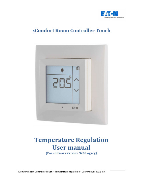
xComfort Room Controller TouchTemperature RegulationUser manual(For software version 3v0.Legacy)`For additional languages and information about xComfort, visitwww.eaton.eu/xcomfort or or use the QR-code. Für weitere Sprachen und Informationen zum xComfort Systembesuchen Sie ww.eaton.eu/xcomfort oder www.xcomfort.de oder verwenden Sie den QR-codeBesok www.xcomfort.no eller www.eato.eu/xcomfort for andrespråk og mer informasjon om xComfort eller bruk QR-koden.Pro další jazyky informace o xComfort návštěvywww.eaton.eu/xcomfort nebo www.xcomfort.cz nebo použijte QR kód.Voor andere talen en meer informatie over xComfort ga naarwww.eaton.nl/xcomfort of www.xcomfort.nl of maak gebruik van de QR-codeTable of contents1. Introduction (1)1.1 Safety instructions (1)1.2 Intended use (1)1.3 Instructions for disposal (1)1.4 About this document (1)2. Room Controller Touch (3)2.1 Operation (3)2.2 Child protection (4)2.3 Cleaning mode (4)2.4 Replacing the batteries (5)2.5 Temperature drop (door/window open) (5)3. Operation mode (6)3.1. General (6)3.2 Basic functions (7)3.2.1 Show the current room temperature (7)3.2.2 Show the current/active setpoint temperature (7)3.2.3 Temporarily adjust the current setpoint temperature (7)3.2.4 Change the setpoint temperature (operation mode) (8)3.2.5 Show the current level of humidity (9)3.2.6 (Optional) Show the outdoor temperature (9)3.2.7 (Optional) Show the floor temperature (9)3.2.8 Show the time and the day of the week (10)3.2.9 (Optional) Touch button(s) (10)3.3 Enhanced functions (11)3.3.1 (Optional) Activate/deactivate the week program (11)3.3.2 (Optional) Select the heating and/or cooling mode (12)3.4 Edit functions (13)3.4.1 Change the pre-defined setpoint temperature (13)3.4.2 (Optional) Edit the week program timer (14)3.4.3 (Optional) Edit the humidity setpoint (17)3.4.4 (Optional) Edit/set the current time and date (18)3.4.5 (Optional) Edit/set the monthly clock correction factor (20)```1. Introduction1.1 Safety instructionsThis document contains important warnings and safety instructions which must be observed and followed by users. Failure to follow these warnings and safety instructions may cause the Room Controller Touch to malfunction.1.2 Intended useThe Room Controller Touch has been designed solely for residential use in private homes and small offices. It is not suitable for industrial use.The Room Controller Touch is designed to facilitate room climate control via an intuitive LCD touchscreen menu.The Room Controller Touch has two operation modes: Control mode for regulating the room climateSensor mode for detecting the room climate and the user settings and communicating these to anintelligent device, e.g. the xComfort Smart Home Controller (SHC), which actually controls the climate in the room.The use of the device for any purpose other than that described in this document, and failure to observe the warnings and safety instructions it contains, will immediately invalidate the warranty and/or any liability claims.1.3 Instructions for disposalDo not dispose of this device with regular domestic waste.Electronic equipment must be disposed of at local collection points for waste electronicequipment and in compliance with the local regulations governing waste electrical and electronic equipment.1.4 About this documentThese operating instructions are intended for end users and describe the operation and menu structure of the Room Controller Touch with software version 3.00.L or higher. This document only describes thefunctioning of the software version ending in ”.L”. The operating instruction for the software version ending in “.U” are described in the user manuals for that version.Note: The software version is displayed during power-up of the Room Controller Touch, e.g.Display ‘123.L’ -> Version: 1.23.L.Certain functions and their availability require the Room Controller Touch to be configured during installation. These functions are marked as (Optional).``2. Room Controller Touch2.1 OperationThe Room Controller Touch is equipped with a backlit display with touch function. The touchscreen is used to display the information needed for operating the Room Controller Touch.Note:The display is designed to respond to push action only. Compared to the touch displays commonly found in smartphones or tablets it may therefore be necessary to press the screen a little more firmly.In the idle state , the display shows the latest selected information menu with the backlight switched off. Once it is touched, the display enters the active state . In this state, the backlight is switched on, and if connected to the xComfort SHC, the display will refresh to get the latest status data.Note:To maximize the battery life, there may be a slight delay between the information displayed in the idle state and the actual status as shown in the xComfort SHC. Themaximum possible delay can be reduced by the installer, but this will lead to a reduction in battery life. In all other configurations the display will always show the latest information.Pre-defined temperature setpoints Frost protection Night / standby EconomyDay / comfortRequest statusHeating request Cooling requestVentilation requestScreen selection Temperature HumidityClockOutdoor temperatureVariousUnits of measurementSettingsTouch buttonFloor temperature (regulation active)Low-battery indicatorWeek program timerWeekly program timer activity statusDay of the weekProgram timer switch time`2.2 Child protectionTo prevent any unwanted changes, the display can be locked by pressing it at the top for approximately 5 seconds until ‘Loc.’ (flashing) appears on the display.To unlock the display, again press the top area for approximately 5 seconds until ‘ULoc’ (flashing) appears on the display.When locked, the Room Controller Touch will ignore any touch activity on the display; if touched, it will display ‘Loc.’ (flashing) for a short period, after which it willl return to the idle state.2.3 Cleaning modeTo prevent any unwanted changes during the cleaning of the Room Controller Touch, the display can be put into cleaning mode.In cleaning mode, the Room Controller Touch will ignore any touching activity on the display. The displaywill then show the remaining time in seconds until the Room Controller Touch switches back to normal operation.>5 Sec.>5 Sec.`2.4 Replacing the batteriesThe Room Controller Touch operates with 2x LR03 (AAA) batteries, which are located in the rear section of the device.Replace the batteries once the low battery indicator appears on the display.Note: Optionally, the Room Controller Touch can also be used with an external power adapter.In this case, batteries are not required. Contact your installer for more information.Used batteries should not be disposed of with regular domestic waste. They should betaken to a battery disposal point.2.5 Temperature drop (door/window open)To prevent energy waste, the Room Controller Touch will automatically turn off the heating for 15 minutes if it detects a rapid temperature drop (a temperature decrease of more than 0.5 °C over a period of 2 minutes), for example if a door or window has been left open. In this state, the heating symbol will disappear and ‘Off’ will appear on the display. This can be overruled by pressing the ‘Off’. The Room Controller Touch will then immediately return to normal operation.>7 Sec.3. Operation mode3.1. GeneralThe operational functions of the Room Controller Touch are grouped as follows:Basic functions (the most frequently used functions)Enhanced functions (functions that are only used occasionally)Edit functions (functions for changing the settings)Note: To start operating the Room Controller Touch and to activate the display, touch the screen once.To maximize the battery life, the Room Controller Touch display will enter the idle state after a period of inactivity. In this state, the display shows the latest selected screen with the backlight switched off. Touching the display will return it to the active state. In this state, the backlight is switched on, and when connected to the xComfort SHC, the display will refresh to obtain the latest status information.Note: To return from the submenus to the main screen, press the ‘screens selection’ area at the top right of the display. The display will automatically switch back to the main screenif it is not touched for 5 seconds.Basic functions (section 3.2)Show the current temperatureTemporarily adjust the current setpoint temperatureShow the current setpoint temperatureChange the pre-defined setpoint temperature (operation mode)Show the current level of humidity(Optional) Show the outdoor temperature(Optional) Show the floor temperature(Optional) Show the time and the day of the week(Optional) Touch button(s)Enhanced functions (section 3.3)Select the regulation mode; heating, cooling, (optional) heating & cooling or OFF mode(Optional) Switch the week program timer ON or OFFEdit functions (section 3.4)Edit the pre-defined setpoint temperatures(Optional) Edit the week program(Optional) Edit the humidity setpoint(Optional) Edit the time and date(Optional) Edit the clock correction factor``3.2 Basic functions3.2.1 Show the current room temperatureThe temperature screen shows the current temperature.3.2.2 Show the current/active setpoint temperatureThis will display the currently active setpoint (desired) temperature for regulating the climate in the room.Note: The active setpoint temperature is the sum total of the pre-defined setpoint temperatureand any temporary adjustment (increase or decrease) that has been programmed.StartStep 1(Optional)Select the heating or cooling setpoint3.2.3 Temporarily adjust the current setpoint temperatureIt is possible to temporarily increase or decrease the current setpoint temperature. Any temporaryincrease or decrease in the setpoint temperature will be reset to zero if the operation mode (pre-defined setpoint temperature) is changed, either manually or via the week program timer.Note: To permanently change the setpoint temperature, see ‘Edit functions – change the pre-defined temperature setpoint’.`StartStep 1Optional selection of heating or cooling setpointStep 23.2.4 Change the setpoint temperature (operation mode)To simplify changing the desired setpoint temperature during the day, the Room Controller Touchsupports four different pre-defined and reprogrammable setpoint temperatures (operation modes). It is possible to manually switch between these pre-defined setpoint temperatures. The pre-defined setpoints can also be used in the week program (if enabled) to automatically switch between the different setpoint temperatures at a set time.Note: Manually changing the active setpoint temperature (operation mode) will deactivate theweek program.StartStep 1`Step 23.2.5 Show the current level of humidityThe Room Controller Touch also measures the humidity levels in the room, and these can be displayed by selecting the humidity screen on the display.3.2.6 (Optional) Show the outdoor temperature Sensor modeIn sensor mode, this option is available if the Room Controller Touch is connected to an intelligent device that provides information about the outdoor temperature.Control modeIn control mode, this option is available if, during installation, the external temperature sensor input is configured for use as an outdoor temperature sensor.3.2.7 (Optional) Show the floor temperatureThis function is available if, during installation, the external temperature sensor input is configured to be used as a floor temperature sensor.`3.2.8 Show the time and the day of the weekThe current time and the day of week can be displayed.3.2.9 (Optional) Touch button(s)The touch buttons of the Room Controller Touch can be used, for example, as pushbuttons to control the lights, shutters/blinds in the room, or to trigger scenes in the xComfort SHC.Note: To implement this function, an actuator or intelligent device must be connected to thetouch button(s) of the Room Controller Touch during installation. Contact your installer for more information.The Room Controller Touch has up to two touch buttons . Their function depends on how they are configured during installation:2x single pushbuttons: Each touch button is connected individually to (an) actuator(s) or to anintelligent device (e.g. the xComfort SHC). The touch button acts as single-pole pushbutton. The touch button supports short pressing (e.g. switching on/off) and long pressing (e.g. dimming up/down).2x single rocker with arrow keys: Each touch button is individually connected to (an) actuator(s)or to an intelligent device (e.g. xComfort SHC). If the touch button is pressed, it will start flashing and the arrow keys will appear, which can be used to scroll up or down. A short press on the ‘up’ key will cause the device to switch on, while a long press will cause it to dim up. A short press on the ‘down’ key will cause it to switch off or to dim down.1x single rocker: Both touch buttons are connected to the same actuator(s). The two touchbuttons will function as one 2-pole pushbutton. The touch button on the left controls the ON/UP (short/long press) function while the one on the right handles the OFF/DOWN function.`3.3 Enhanced functions3.3.1 (Optional) Activate/deactivate the week programThe week program can be deactivated (OFF) or activated (ON). If it is deactivated, it is only possible to manually switch between the pre-defined setpoint temperatures (operation mode); if it is activated, the operation mode will be based on the programmed week program.Control modeIf the week program timer function is enabled during installation (MRF), the option to activate or deactivate the week program will be available in control mode only.Sensor modeIn sensor mode, this option is available if the device is connected to the xComfort SHC, otherwise the week program will not be available.Note: If the week program is activated (ON), the device will switch to the correct operation modein accordance with the week program for the current time.StartStep 1Step 2Step 3TimeoutDeactivated (OFF) Activated (ON)`3.3.2 (Optional) Select the heating and/or cooling modeSensor modeIf the Room Controller Touch is connected to an xComfort SHC, it is possible to manually change between ‘heating’ and ‘cooling’. In this case, the ‘heating & cooling’ mode will not be available. If connected to a Room Manager, the temperature regulation mode cannot be changed.Control modeThe available regulation modes depend on the configuration. If only a heating or a cooling actuator is connected, the temperature regulation mode cannot be changed. If both actuators are connected all modes are available.StartStep 1(Show mode)The currently active mode is shownStep 2(Select mode)Control modeSensor mode`3.4 Edit functions3.4.1 Change the pre-defined setpoint temperatureThe Room Controller Touch supports up to 2 x 4 different pre-defined setpoint temperatures (operationSensor modeIf connected to the xComfort SHC, the pre-defined temperature values are the same as the temperature setpoints in the SHC. Any manual change on the Room Controller Touch will also change the setpoint in the SHC (and vice versa). If connected to a Room Manager, the predefined temperature setpoints are used as offset values for the Room Manager’s current setpoint temperature.Control modeThe initial values used in control mode have to be programmed during installation (MRF). These setpoint values are used by the Room Controller Touch for climate control.Note:If the ‘heating & cooling’ mode is active, the Room Controller Touch will maintain aminimum temperature difference between the heating setpoint and the cooling setpoint temperature (dead zone) to prevent continuous switching between heating and cooling. This dead zone value can be configured during installation. The default value is 3 K.StartStep 1`Enter edit mode Step 2(Select edit)Edit icon is flashingEdit the setpoint temperatureOptionalSelect the setpointOptionalSelect the heating or cooling setpointStep 3 (Change)Changed value is flashingLeave edit mode Step 4Timeout or3.4.2 (Optional) Edit the week program timer Sensor modeIf connected to an intelligent device, the latter will manage the climate control function based on the week program that has been configured on that device. Any changes to the week program should therefore be made on the intelligent device.`Control modeIn control mode, the week program timer will only be available if it is enabled during installation (MRF). For each day of the week, the Room Controller Touch supports up to 6 manually (re-)programmable timeslots during which it will switch from one setpoint temperature (operation mode) to another.StartStep 1Enter edit modeStep 2 (Select edit)Edit icon is flashingStep 3(Enter program edit)The day of the week and thetrigger point are flashing Enter program editSelect the day of theweekThe selected day of the weekis flashing`Select the switch pointThe selected switch point is flashingChanging the pre-defined setpointThe selected setpoint is underlinedThe minutes are flashingChange the time (hours)The hours are flashing`Leave edit mode (Leave edit mode)Timeout or3.4.3 (Optional) Edit the humidity setpoint Sensor modeThe humidity setpoint is not available if the Room Controller Touch is connected to an intelligent device, e.g. a xComfort SHC or Room Manager.Control modeThe humidity setpoint can be changed manually. This function is available in control mode if a humidity actuator is connected to the Room Controller Touch during installation. Note: During installation, the installer must set when the Room Controller Touch sends an ONcommand to the actuator. Either if the humidity level is above or if it is below the setpoint. The ventilation icon is displayed when the ON command has been sent.Select the humidityEnter edit modeChange`Leave Timeout or3.4.4 (Optional) Edit/set the current time and date Sensor modeThe option to set the time and date manually is not available if the Room Controller Touch is connected to an xComfort SHC. In this case, the time and date are synchronized with the time and date of the xComfort SHC.Control modeThe time (hours, minutes) and date (day of the month, month, and year) can be set manually if the week program is enabled during installation.Select the clockEnter edit mode`Once changed, the changed value will Leave edit modeTimeout or`3.4.5 (Optional) Edit/set the monthly clock correction factorIf the internal clock of the Room Controller Touch is inaccurate, it is possible to configure the number of seconds by which the clock needs to be corrected each month (-99 to +99 seconds).Note: The accuracy of each clock may vary slightly, which may cause it to go out of sync with thecurrent time. This will then cause the week program to switch to the desired setpoint temperature either too early or too late.This option is only available if the clock function is enabled during installation and if the Room Controller Touch does not receive the time and date from another device.Select the clockEnter editPress edit > 5 SecChangeLeave edit© Eaton Industries (Austria) Eugenia 13943 SchremsAustriawww.eaton.eu/xcomfort`。
CM+机房精密空调简易操作手册

注2:通常在特殊应用场合下才会使用送风温度作控制,需要增加送风传感器选配件。如要求对送风温度作控制时,由于湿度控制点仍是以回风相对湿度传感器作参考,所以以上三个设定点参数均需按特定要求进行设置。
6
维护周期是一组实时计时器用来对需定期维护的部件的运行时间进行计时设定。当部件运行时间到达设定时间时,便会触发告警来提醒维护人员对系统或部件进行维护。有三个项目可设定维护服务周期:制冷系统、过滤器及加湿器。
注:如果告警条件未能有效消除,控制复位后告警仍会再次发生。
5
在该菜单内用上移 / 下移键(UP / DOWN)将光标移动至所需设定项目,按回车键(ENTER)将光标跳至数值位置,使用上移 / 下移键(UP / DOWN)对数值进行增减,设定值调整好后,按输入键(ENTER)确认并可选下一个设定项目。
注:与英文操作系统不同,中文操作系统显示每一个告警信息是用一整幅屏幕显示,所以需一页页滚动检查。
4.2
该菜单显示100个的历史告警记录。每个告警信息都注有日期时间(发生时刻及持续时间)。采用上移或下移键(UP / DOWN),可以使存储的告警信息在屏幕上作上下连续滚动显示。
4.3
手动告警复位,如高压保护和低压保护,只有在该菜单内才能重设。当一个告警存在时,其状态以“开”(ON)来表示。欲对其进行控制复位,可使用(UP / DOWN)键将光标移至该项目,按ENTER键,光标即移至“否”(NO)的位置,然后再采用UP/DOWN键选定“是”(YES)选项,按ENTER键确认设置。
3
在主运行显示状态时,按回车键(ENTER)或上移键(UP)或下移键(DOWN),便可从主运行显示状态转为进入控制菜单。进入控制菜单有三个级别的密码。进入一般控制信息菜单无需密码。操作员只需按回车键(ENTER)四次(0000)便可进入主菜单。第一级密码适用操作人员进入控制,第二级密码适用专职维护人员,而第三级密码仅供工厂技术人员使用。需要密码才能打开的菜单在它的标题后均注有[1] / [2] / [3]来表示所需密码级别。
C1002控制器使用说明书

STULZ精密空调简易操作资料C1002控制器中文操作资料空调常见故障判断及处理STULZ C1002精密空调操作资料1STULZ C1002精密空调操作资料2STULZ C1002精密空调操作资料3STULZ C1002精密空调操作资料4STULZ C1002精密空调操作资料5STULZ C1002精密空调操作资料6STULZ C1002精密空调操作资料空调常见故障判断及处理1、更换热保护器2、清洗或更换滤网3、调整或更换皮带1、热保护器坏2、过滤网脏3、风机皮带太松电加热故障HEA 1、倒换相序2、检查三相电源是否正常3、闭合空开/更换保险管4、调整皮带,清洗滤网5、调整、更换气流开关6、改造回风1、AC 电源反相2、AC 电源缺相/不正常3、风机空开未闭合/保险管坏4、皮带松,滤网脏5、气流开关失灵6、回风不好气流报警FLO11、查漏后补氟里昂2、更换膨胀阀3、清洗过滤网4、改造回风5、更换低压保护开关6、更换干燥过滤器7、更换管路电磁阀或线圈8、修改设定值1、A/C 系统缺氟漏氟2、膨胀阀失灵3、过滤网脏4、回风不好5、低压保护开关坏6、干燥过滤器脏堵7、管路电磁阀或线圈坏8、温度设置太低低压报警LOP1清洗或更换过滤网1、清洗室外机2、更换室外风机3、检查线路及开关4、高压开关复位5、更换高压保护开关故障处理过滤网脏1、室外机太脏2、室外风机堵转3、室外机无电源4、高压开关未复位5、高压保护开关坏原因过滤网脏堵FIL 压缩机高压报警HIP1报警内容7STULZ C1002精密空调操作资料8STULZ C1002精密空调操作资料9。
精密空调操作方法

精密空调操作方法
1. 打开空调控制面板或遥控器的电源开关。
2. 调整温度设置。
在控制面板或遥控器上选择您想要的温度设定。
通常有“+”和“-”按钮来逐渐调整温度。
3. 选择运行模式。
根据您的需求选择适当的运行模式,如制冷模式、制热模式、除湿模式、通风模式等。
此外,也可以选择自动模式,让空调根据环境自动调整运行模式。
4. 调整风速设置。
根据喜好和需求,选择低、中、高等风速设置。
通常,有相应的按钮来进行风速调节。
5. 调整风向设置。
有些精密空调可以调整风向,通常通过控制面板上的相应按钮或遥控器上的风向按钮来实现。
6. 等待空调达到设定温度。
一般情况下,空调会自动调节室内温度,直到达到所设定的温度。
从而保持室内环境的舒适度。
7. 关闭空调。
不需要使用空调时,可以将温度设定为稍微高于室内温度,或者直接关闭整个空调系统,以节省能源。
请注意,不同的精密空调品牌和型号可能会有略微不同的操作方法,因此最好参考相应的用户手册以获取准确的操作指南。
c6000中文说明书-精密空调机组微处理控制器操作手册
Stulz C6000控制器第52索引精密空调机组微处理控制器操作手册目录页码简介 (3)安全须知 (3)页码代号 (3)控制器说明 (4)操作界面 (6)控制器操作 (7)菜单对话框和参数说明启动窗口.............................................................................. .. (8)标准窗口 (9)“信息”菜单..................................................................... ......... .. 10“控制”菜单................................................................................. .... .12“服务”菜单................................................................................. . (17)功能说明监控器操作.................................................................................... (26)GE操作 (27)干冷器操作 (28)两套系统的顺序控制 (29)总线顺序控制 (31)数字自控连接 (32)备份运行 (34)传感器的故障 (36)信号....................................................................................... (37)控制器出厂时的设........................................................................ (40)控制图....................................................................................... (42)硬件说明控制器.......... .. (44)下载新软件 (45)标准I/O板 (48)扩展I/O板 (52)温度/湿度传感器 (54)系统配置带I/O板的C6000的电路图 (55)第一模块带监控器的C6000的电路图 (55)第二模块带监控器的C6000的电路图 (56)打印机连接 (57)电脑连接 (57)故障排除 (58)信息水平概述 (59)控制水平概述 (60)服务水平概述 (61)简介本手册对控制器的操作和设计进行了说明,控制器组成了空调单元的中央控制站,整个空调都是由控制器控制和检测的。
精密空调说明书
ENV50204
RADIATED ELECTROMAGNETIC FIELDS
满足的其它相关安全标准还有:
机房专用空调
SCA
系列
SCA 系列机房空调
本手册适用的空调机组信息: 机组型号 选件 机组序列号 电路图号
本使用说明书(包括其它附件)随机组一起提供,请您妥善保管, 以便于在需要时能随时查看。万一此说明书不慎遗失或损坏,请直接 向制造商索取。
亲爱的依米康用户
衷心感谢惠购依米康 SCA 系列机房空调。为确保本产品的安 全 且持久无故障运行,在使用本产品之前请务必认真阅读本使用手册及 安全使用之注意事项。
依米康机房空调机身,完全由结构框架面板封闭。因此人或动物不能从外部进入内部危险的区域。包 括室外风机,都安装配置了完善的风机罩,确保了安全。
依米康 1
安全
依米康空调满足的安全规范和标准
满足中华人民共和国国家制冷专业标准有:
GB/T 19413-2003 计算机和数据处理机房用单元式空调调节机组 GB/T 17758-1999 单元式空气调节机 GB/T 7778制冷剂编号方法和安全分类
安全
安全
本手册包含了正确和安全使用、维护依米康机房空调的基本信息。除了遵守总的安全标准以外,尤其 要随时注意有特殊安全标记的地方。
本手册中的安全标记
!
:一般危险标志。表明该内容的错误操作可能对人造成伤害。
:有电危险标志。表明该内容操作有电,可能造成人员触电或损坏设施。
ATTENTION!
:警惕标志。表明对该内容的操作要特别小心,否则会损坏空调机组或功能部 件。
满足 EMC 电磁兼容性标准 2004/108/EC 中的相关标准有:
EN61000-6-4
Carrier空调系统使用手册说明书

Owner’s ManualA NOTE ABOUT SAFETYAny time you see this symbol in manuals, instructions and on theunit, be aware of the potential for personal injury. There are three levelsof precaution:W ARNING signifies hazards that could result in personal injury ordeath.CAUTION is used to identify unsafe practices which would result inminor personal injury or product and property damage.NOTE is used to highlight suggestions which will result in enhancedinstallation, reliability, or operation.ABOUT YOUR AIR CONDITIONING SYSTEM Our products are designed, tested and built in accordance with US Department of Energy standardized procedures and other standards; however, actual operating results and efficiencies may vary based on manufacturing and supplier tolerances, equipment configuration, operating conditions and installation practices.Identifying Your SystemYour new Carrier cooling system is what we call a ”split system.” It has an outdoor unit and an indoor unit connected to each other with copper tubing called refrigerant lines. Each of these units has a rating plate with the model and serial numbers you will need to reference when calling an authorized Carrier dealer about your system.Take a few moments now to locate those numbers and record them in the spaces provided on the cover of this booklet.USING YOUR NEW CARRIER SYSTEM Your air conditioning system is controlled by a wall-mounted Infinity Touch Control or thermostat installed inside your home. See the Infinity Touch or thermostat Homeowner Guide for more details on system operation.INFINITY VARIABLE SPEED OPERATION You may notice your system runs for longer periods of time. This system is designed to meet the cooling needs of the home at a wide range of conditions. Your indoor temperature will remain more consistent with fewer drafts, better humidity control, enhanced comfort and enhanced energy efficiency.COOLING YOUR HOMEFor cooling operation, make sure the System or Mode control is set to the appropriate mode. Then, adjust the Temperature control to your desired setting. Finally, use the Fan control to select Automatic or On (runs continuously).OPERATION UNDER EXTREME CONDITIONS Your air conditioner will run as long as necessary to maintain the indoor temperature selected on your Infinity Touch Control or thermostat. On extremely hot days, your air conditioner will run for longer periods at a time than on moderate days. Your system will also run for longer periods of time under the following conditions:•Frequent opening of exterior doors•Operating laundry appliances•Taking hot showers•More than the usual number of people present in the home •More than the normal number of electric lights in use•Drapes or blinds are open on the sunny side of the homeSOUNDYour new Infinity 19VS air conditioner is different from most cooling systems. Because this is a variable speed system, it is designed to operate at different speeds depending on the temperature and humidity conditions. You may notice the sound coming from the outdoor unit changing from time to time depending on the weather conditions. The higher speed produces a higher sound. This change of speed allows the system to operate more efficiently and maintain comfortable conditions inside the home as the outdoor temperature rises. You may also hear a slight hissing sound when near the outdoor unit in the off-cycle. This is the sound of system pressure equalization which is required to enable soft and easy starting of the next cycle. These sounds are normal and do not represent a problem with your system.ROUTINE MAINTENANCESimple, routine maintenance as described below will enhance your air conditioner system’s ability to operate economically and dependably. Always remember the following safety precautions:24VNA9Infinity® 19VS Variable Speed Air Conditionerwith Puron® Refrigerant!PERSONAL INJURY, DEATH AND / OR PROPERTYDAMAGE HAZARDFailure to follow this warning could result in personal injury, death orproperty damage.Improper installation, adjustment, alteration, service, maintenance, oruse can cause explosion, fire, electrical shock, or other conditionswhich may cause personal injury or property damage. Consult aqualified installer, service agency, or your distributor or branch forinformation or assistance. The qualified installer or service agencymust use factory-authorized kits or accessories when modifying thisproduct.Read and follow all instructions and warnings, including labels shippedwith or attached to unit before operating your new air conditioner.CAUTION!CUT HAZARDFailure to follow this warning could result in personal injury.Although special care has been taken to minimize sharp edges in theconstruction of your unit, be extremely careful and wear appropriateprotective clothing and gloves when handling parts or reaching into theunit.WARNING!ELECTRICAL SHOCK HAZARDFailure to follow this warning could result in personal injury or death.Before installing, modifying, or servicing system, main electricaldisconnect switch must be in the OFF position. There may be more than1 disconnect switch. Lock out and tag switch with a suitable warninglabel.NOTE: There may be more than one electrical disconnect switch.©2019 Carrier Corp.• 7310 W. Morris Street • Indianapolis, IN 46231Edition Date: 09/19Catalog No: OM24VNA9-03Replaces: OM24VNA9-0224VNA9: Owner’s ManualManufacturer reserves the right to change, at any time, specifications and designs without notice and without obligations.2•Keep Filter CleanA clogged or improperly installed air filter on your indoor unit will increase operating costs and shorten the life of the unit. For detailed filter cleaning information refer to indoor unit literature.•Do Not Block Floor, Wall or Ceiling VentsWhen drapes, furniture, toys or other common household items block vents, the restricted airflow lessens the system’s efficiency and life span. •Do Not Cover or Block Outdoor UnitThe outdoor unit needs unrestricted airflow. Do not cover it or place items on or next to it. Do not allow grass clippings, leaves, or other debris to accumulate on the sides or top of the unit. And, maintain a 12”(305 mm) minimum clearance between the outdoor unit and tall grass,vines, shrubs, etc.•Check Condensate DrainYour air conditioner removes humidity from your home during the cooling season. After a few minutes of operation, water should trickle from the condensate drain of the indoor coil. Check this occasionally to be sure the drain system is not clogged. Drainage will be limited if you live in a very dry environment.•Do Not Operate Below Minimum Operating Temperatures in Cooling ModeYour outdoor unit is not designed to operate below the minimum temperatures shown below. The minimum temperature depends on which wall control is being used:—With Infinity Touch Control: 40°F (4°C)—With Thermostat Control: 55°F (13°C)System protections may not allow the unit to operate below these minimum temperatures.•Base Pan DrainagePeriodically check for and remove debris that has settled around the base of your outdoor unit. This will ensure proper drainage of the base pan and eliminate standing water inside the outdoor unit. •Level InstallationYour Carrier dealer will install the outdoor unit in a level position. If the support base settles or shifts and the unit is no longer level, be sure to re-level it promptly to assure proper drainage. If you notice water or ice collecting beneath the unit, arrange for it to be drained away from the unit.SEA COAST COIL MAINTENANCECoastal locations often require additional maintenance of the outdoor unit due to highly corrosive airborne ocean salt. Although your new Carrier system is made of galvanized metal and is protected by top-grade paint, take the additional precaution of periodically washing all exposed surfaces and the outdoor coil approximately every 3 months. Consult your installing Carrier dealer for proper cleaning intervals and procedures for your geographic area or ask about a service contract for regularly scheduled professional cleaning and inspections.TROUBLESHOOTINGBefore you request dealer service, check for these easily solved problems:•Check the indoor and outdoor disconnect switches Also check your main electrical panel circuit breakers or fuses.•Check for sufficient airflow. Air filter(s) should be reasonably clean and interior vents should be open and unobstructed.•Check Infinity Touch Control or thermostat settings. For cooling,your desired temperature setting should be LOWER than the displayed room temperature, and the System/Mode control should be on Cool or Auto.•Time delays - depending on the Carrier air conditioner you have, there may be delays in unit operation that are built-in to protect the equipment and your comfort. Don't be alarmed if you notice a time delay in operation. It may be a standard protection feature of your equipment. Check with your Carrier Dealer for more information on time delays.If you need to contact your Carrier dealer for troubleshooting and/or repairs, be sure to have the model and serial numbers of your equipment available (there are spaces on the cover for you to write this information).REGULAR DEALER MAINTENANCEIn addition to the routine maintenance that you perform, your home comfort system should be inspected regularly by a properly trained service technician. Many dealers offer this service at a reduced rate with a service contract. Some service contracts offer additional benefits such as parts discounts and no additional charge for ”after hours” or emergency service.* Monthly maintenance items and outdoor unit rinsing may be performed by the consumer. All other maintenance items and all service work must be performed by a qualified service technician. Read all waring labels.Notes:1.The above list may not include all maintenance items. Inspection intervals may vary depending on climate and operating hours. Consult your HV AC dealer about a service contract for seasonal inspections.2.Do not use harsh chemicals or high pressure water on coils. More frequent rinsing is required for units near a sea coast.Maintenance ChecklistRecommendedInterval*Outdoor unit specific:Monthly AnnualClear away debris and vegetation near unit.XInspect cabinet for damage. Replace components that are damaged or severely rusted.X Inspect electrical disconnect for proper function. Repair or replace as necessary.XInspect electrical wiring and connections. Tighten loose connections. Inspect and perform functional test of equipment as needed to ensure proper function. Repair or replace damaged or overheated components and wiring.X Check refrigerant system subcooling and/or superheat (system dependent).X Inspect inside of unit. Clean if debris is present.X Inspect condenser coil. Clean if dust, dirt, or debris is present. Rinse unit with fresh water (see Note 2).X Inspect motor and fan for damage. Make sure fan spins freely.XIndoor specific: (for fossil fuel furnaces and accessories, refer to unit specific literature)Inspect, clean, or replace air filter if dirty.XInspect and clean blower assembly (includes blower housing, wheel, and motor).X Inspect internal and external of cabinet. Clean as needed.X Inspect electrical disconnect for proper function. Repair or replace as necessary.X Inspect electrical components, wiring, and connections. Tighten loose connections. Repair or replace damaged components and wiring.X Inspect evaporator coil. Clean if dust, dirt, or debris is present (see Note 2).X Clean condensate pan, trap, and drain lines (more frequent maintenance may be required in humid climates - consult your local HVAC dealer).X Inspect airflow system (ductwork). Check for leaks and repair as needed.X。
卡洛斯精密空调操作手册

卡洛斯精密空调操作手册1. SL1600-TH3 恒温恒湿机控制器概述SL1600 总结了多年使用经验,在抗干扰方面有更加出色的表现,整套控制器所有端口通过了更严格的EMC 测试:电快速脉冲 4 千伏;浪涌 4 千伏;传导抗干扰150K~80M。
该控制器可以根据用户需求搭配不同的手操器(显示器),并且支持远程监控。
1.1. 安全要求请务必详尽阅读"安全要求",并严加遵守各项安全要求。
妥善保管好该使用说明书,以便相关人员随时取阅。
指定电源为控制器供电,切勿与其它电器共用同一电源,以免导致负荷过大的危险。
务必保证控制器可靠接地并经常检查接地是否牢固,接地不当可能导致触电的意外。
安装时请遵守强弱电分离的原则。
按照"安装尺寸图"、"电气连接示意图"等图安装连线。
把控制器安装在不会有雨雪、废弃物等聚集、阳光暴晒的地方。
稳固安装控制器,以防控制器跌落伤人或损坏。
开关电源输入,85~264AC。
输出继电器AC220V/5A。
切勿拉扯、扭曲电源线、通讯线以免产生严重故障。
用户如有任何修理的需要,请与制造商联系,切勿自行修理。
1.2. 控制板的资源1.3. 主要性能指标及技术特点1. 电源电压:三相220V AC/50Hz;2. 控制器空载消耗功率:10W;3. 使用环境:工作环境温度范围-10~70℃,5%RH相对湿度95%RH(无凝露)4. 保存环境:温度范围-25~85℃,相对湿度95%RH(无凝露)外型尺寸204x150x48mm开孔尺寸192 x 138 mm显示尺寸118 x 90 mm特点和功能采用开关电源供电,电压适应范围广,可以在开闭压缩机的瞬间都保证正常的供电;●通过多层次高低频滤波,有效过滤复杂电磁环境中的电流或者电磁干扰;●主机和控制面板采用差分带校验的通讯方式,被动接收和主动查询的方式相互结合,使主机●和控制面板保持高度一致,使通讯非常稳定可靠;●所有输入和输出点均采用稳压5V 控制,有效避免电压波动引起的误动作;●通讯距离1000 米(手操器与主板的距离);●预留RS485 MODBUS 远程监控接口;●集成电极加湿器控制,也可灵活搭配不同类型的加湿器。
精密空调操作指导书

Work Instruction作业指导Business & Industry Services标题Title: 精密空调操作指导书编号Number:IDC-G.111.HQ发启者Sponsor: 设施管理区域运作经理FM Senior Manager\ Regional Ope.Manager生效日期Effective Date:2015年5月1日作者Owner: 数据中心运作团队Data center operations team版本Revision:00SUMMARY OF CHANGES变更信息∙初始编制PURPOSE目的∙确保制冷设备运作正常,保证数据中心供冷的可靠性;SCOPE范围综合IFM 工程POM保洁HSK绿化GRD行政ADM保安SEC特殊情况、例外说明Specific Applicability / Variance / Exceptions工厂Manufacture 无办公楼Office研发/数据中心R&D center物流仓储Logistic公共机构Public DESCRIPTION 描述精密空调操作指导书System/Equipment 系统简述原理Liebert.PEX冷冻水系列空调是一种中大型的精密环境控制系统。
采用冷水机组提供的冷冻水制冷,配有电加热和加湿器。
组成冷冻水空调机组包括换热器、远红外加湿器、风机、电加热、水流量调节阀、微处理控制器等部件。
系统图或操作面板图报警指示灯有报警产生时,报警指示灯呈红色;报警消除时,报警指示灯熄灭。
2.工作指示灯机组工作时,工作指示灯呈绿色;机组关闭时,工作指示灯呈黄色。
3.开/关键作用一:开关机。
系统运行时,按下开关键,系统关闭;系统关闭时,按下开/关键,系统开启。
注意系统上电后机组的运行状态将按照上次掉电时机组的运行状态,例如在掉电时系统若处于工作状态,那么上电之后系统将自动进入运行状态,无须用户手动开启。
精密空调操作SOP
精密空调操作SOP
开机前注意事项,必须待风阀完全停止后开机,按开机键,机组的启动关闭不能过于频繁,间隔时间大约两分钟。
本机组操作密码为0001,可以对机组的温湿度进行修改。
平时在无专业人员指导下请勿打开门板,内有380伏高压,请注意人身安全。
机组正面有个液晶显示屏,可显示当前机房温湿度状态。
设定值进行设定时,需要先输入密码,然后使用上移、下移键浏览各选项,最后按回车键进入各选项菜单。
机组巡视第一步则是查看空调是否正常运行,有无报警,运行时有无杂音。
不建议温湿度调到极端值,如温度最低16度或湿度80%以上,以免造成机房其他设备、人员等意外情况发生;如确实必要,必须在有人看管情况下,温湿度正常后调回机组开机时设定值为宜。
系统的显示屏上检查空调系统的各项功能及参数是否正常,有无报警蜂鸣,如有报警则要检查报警记录,并打电话报修,切勿自行复位,防止故障扩大。
检查温湿度的工作状况是否正常
过滤器的检查:需要停机进行,听到风机精致无声音再打开门板,拆下看外观是否尘土已经布满病且黑乎乎的,本过滤器是白色的。
皮带的检查:需停机检查,待风机完全静止,查看皮带有无磨损,松紧度是否适当,必要时更换皮带。
加湿,制冷的检查:加湿时灯管有无工作(高温,不可触摸),压缩机有无拉霜,异响等,发现问题,需立即报修。
cooistar空调遥控器说明书

cooistar空调遥控器说明书cooistar空调遥控器按键功能(1)“开/关”键:待机时按一下开机,进入运行状态,开机后按一下关机,进入关机待机状态;(2)“模式”键:开机后,按此键,模式按“自动热→自动”方式顺序循环;→低风→中风→高风→自动→制冷→除湿→送风→制(3)“风速”键:按此键,内风机风速按“自动”方式循环;(4)“风向”键:按此键,导风片角度按“自动位置[4]→位置[5]→自动”方式顺序循环;→位置[1]→位置[2]→位置[3]→(5)“摆风”键:按此键,摆风可设置为连续摆动和点动两种方式循环;(6)“温度▼”键:按一下设定温度下降一度,控制范围:16℃—31℃,无连击功能;(7)“温度▲”键:按一下设定温度上升一度,控制范围:16℃—31℃,无连击功能;(8)“定时开”键:时间设置好后,按一下“定时开”键,数字显示区显示上次设定的定时开机时间,通过“小时”键和“分钟”键调整设定时间,空调到设定时间开机;再次按“定时开”键,可取消定时开设定;(9)“定时关”键:时间设置好后,在开机状态下,按一下“定时关”键,数字显示区显示上次设定的定时关机时间,通过“小时”键和“分钟”键调整设定时间,空调到设定时间关机;再次按“定时关”键,可取消定时关设定;(10)“小时”键:在定时和时间设置状态下,按一下增加一小时,有连击功能;(11)“分钟”键:在定时和时间设置状态下,按一下增加十分钟,有连击功能;(12)“睡眠”键:按此键,遥控器显示睡眠模式设定,在睡眠显示区域一直显示“”符号,室内风机自动转为低风,8小时后睡眠结束,睡眠符号取消,室内风机恢复原来风速运行;再次按“睡眠”键或按一下“模式”键或“风向”键可退出睡眠功能;(13)“复位”键:用直径1mm的小圆棒按此按键,遥控器恢复出厂设置;(14)“时间”键:用直径1mm的小圆棒按此按键,进入时间设置状态,设定好后,再次按此按键表示设定完成且退出时间设置;注:每次有效操作遥控器按键,液晶屏显示发射信号的符号“”亮一秒后消失。
- 1、下载文档前请自行甄别文档内容的完整性,平台不提供额外的编辑、内容补充、找答案等附加服务。
- 2、"仅部分预览"的文档,不可在线预览部分如存在完整性等问题,可反馈申请退款(可完整预览的文档不适用该条件!)。
- 3、如文档侵犯您的权益,请联系客服反馈,我们会尽快为您处理(人工客服工作时间:9:00-18:30)。
1. SL1600-TH3 恒温恒湿机控制器概述SL1600 总结了多年使用经验,在抗干扰方面有更加出色的表现,整套控制器所有端口通过了更严格的EMC 测试:电快速脉冲 4 千伏;浪涌 4 千伏;传导抗干扰150K~80M。
该控制器可以根据用户需求搭配不同的手操器(显示器),并且支持远程监控。
1.1. 安全要求请务必详尽阅读"安全要求",并严加遵守各项安全要求。
妥善保管好该使用说明书,以便相关人员随时取阅。
指定电源为控制器供电,切勿与其它电器共用同一电源,以免导致负荷过大的危险。
务必保证控制器可靠接地并经常检查接地是否牢固,接地不当可能导致触电的意外。
安装时请遵守强弱电分离的原则。
按照"安装尺寸图"、"电气连接示意图"等图安装连线。
把控制器安装在不会有雨雪、废弃物等聚集、阳光暴晒的地方。
稳固安装控制器,以防控制器跌落伤人或损坏。
开关电源输入,85~264AC。
输出继电器AC220V/5A。
切勿拉扯、扭曲电源线、通讯线以免产生严重故障。
用户如有任何修理的需要,请与制造商联系,切勿自行修理。
1.2. 控制板的资源1.3. 主要性能指标及技术特点1. 电源电压:三相220V AC/50Hz;2. 控制器空载消耗功率:10W;3. 使用环境:工作环境温度范围-10~70℃,5%RH相对湿度95%RH(无凝露)4. 保存环境:温度范围-25~85℃,相对湿度95%RH(无凝露)外型尺寸204x150x48mm开孔尺寸192 x 138 mm显示尺寸118 x 90 mm特点和功能采用开关电源供电,电压适应范围广,可以在开闭压缩机的瞬间都保证正常的供电;●通过多层次高低频滤波,有效过滤复杂电磁环境中的电流或者电磁干扰;●主机和控制面板采用差分带校验的通讯方式,被动接收和主动查询的方式相互结合,使主机●和控制面板保持高度一致,使通讯非常稳定可靠;●所有输入和输出点均采用稳压5V 控制,有效避免电压波动引起的误动作;●通讯距离1000 米(手操器与主板的距离);●预留RS485 MODBUS 远程监控接口;●集成电极加湿器控制,也可灵活搭配不同类型的加湿器。
1.4. 产品简介SL1600-TH3 超强的稳定性能及轮值功能,为机房空调一天24 小时运行提供了保障。
控制器灵活性的控制逻辑,能够实现最大限度的节能及精确的温湿度控制。
本控制板适用恒温恒湿精密机房空调柜机或恒温恒湿空气处理机。
控制板可控制 2 个压缩机,2 组电加热,电加热亦可采用0~10V 的可控硅控制。
一个加湿器。
加湿器即可选用开关量控制,也可选用模拟量控制。
作为空气处理机控制器时,有制冷阀及制热阀,这两个阀要求是0~10V 的输入信号。
2. 操作说明2.1. 主窗口开机后显示10 秒钟的厂家欢迎页面,然后显示主窗口,通过主窗口查看当前室内温度,室内湿度,当前设定温度,设定湿度。
还可进入温度曲线页面、湿度曲线页面、中英文切换、设置页面、输出输入页面、故障复位及"开启/关闭"主机。
在主界面按"开机"键进入运行状态,界面上机组状态显示由"停止"变成"运行",系统启动:首先启动送风机60 秒后根据实际的温湿度情况决定启动那种运行模式。
2.2. 输出查询按"输出"可查询哪些设备在工作状态,哪些设备不在工作状态。
另可查询 1 号压缩机、2 号压缩机、电极加湿器、整机工作时间。
2.3. 输入查询按"输入"可查询哪些设备在工作状态,各输入点的工作情况。
2.4. 用户参数设定2.4.1. 温湿度设定温度和湿度的显示以及设定都可精确到小数点后 1 位。
进入到"设置窗口",分别单击"温度设置"、"温度校正"、"湿度设置"、"温度校正"后的数字,弹出小数字键盘,输入参数数值后按"确定"键确认设定值。
注意:1、温度设定范围为:18~35 度;2、湿度设定范围为:30%RH~80%RH;3、温度校准范围为:-9.9 度~9.9 度;4、湿度校准范围为:-20%RH~20%RH;5、如果超出设定范围,系统会有滴滴滴提示声。
2.4.2. 手动排水当需要把加湿桶里的水放掉的时候,在设置菜单里,按下"手动放水"后的按键,加湿电极断电,进排水电磁阀同时打开,3 秒钟之后进水阀关闭,再按"手动放水"按键停止排水,或10 分钟后系统自动恢复正常工作状态。
排水或者定时清洗后系统会重新启用二次进水,先补水到50%电流在延时 3 分钟再次进水到额定电流。
2.4.3. 用户参数设置2.4.4. 定时开关机在"设置窗口"单击"下一页",进入定时开关机设置。
单击"定时功能"后的按键,在"选择"和"不选择"之间切换,"选择"表示开启定时开关机功能,"不选择"表示关闭此功能;点击"开机时间"或"关机时间"上时间的数字,弹出数字键盘,输入要设置的数值后按"确认"键完成"开机时间"或"关机时间"的设置。
2.5. 高级设置一由于机组"高级设置一"为工程商设置,不对用户开放,所以系统提供了密码保护的功能,在密码输入正确的情况下,方可设置,否则无法进入"高级设置1"状态。
在设置窗口显示状态点击"高级设置"选项后的星号的位置,此时弹出数字键盘,输入密码"1111",按数字键盘上的确认键确认密码输入,此时按星号后的"确认"键,即可进入高级设置页面。
注:1、受密码保护的参数有:1)运行模式设置:自动/手动;2)手动调机设置;3)输入点常开/常闭设置;4)时间设置:低压延时设置、压缩机最短运行时间、压缩机最短停机时间、启动延时时间、普通报警延时;5)探头设置:送风探头、冷却出水/翅片1探头、冷却回水/翅片2探头的使用或禁用;6)系统设置:温度精度设置、湿度精度设置、制冷开冷凝温度、送风温度过高、送风温度过低、出回风温差过大;7)系统配置:压缩机个数设置、电加热个数设置、制热方式、制冷方式、是否采用电极加湿、第一个模拟量输出、第二个模拟量输出、能量阀与除湿阀的切换。
8)时间设置和工程商密码管理2、当退出"高级设置1"页面后,密码将无效,如需要再次进入高级设置页面,需要再次输入密码。
输入密码后,进入"高级设置",可通过修改各选项后的参数来完成设置。
2.5.1. 工程商参数设置注:制冷及制热的1、2 级上下限,在设置后,须按"完成"才可以进行设置。
2.5.2. 轮值管理功能在无人值守机房,启用轮值功能,能使机组轮流工作,延长机组寿命;在制冷、制热不足或有机组故障的情况下,能开启备用机组,提高效率。
在"系统设置"中,可进行轮值功能的设置定时轮换工作。
轮值时间0~99小时可调,缺省8小时,步长1小时,轮值时间为0时,为轮值测试,对应轮值时间为4分钟,轮值系统的机组台数。
只有一台处于待命状态,其余则投入运行。
确定的轮值时间超过,待命机组将按地址的顺序发生轮换。
故障轮值:若某一台当值机组发生报警,另一台待命的机组即会启动。
由主令机组(机组1)通过开关量输入和输出给待命机组和当值机组发送开停机指令,这一指令每10 分钟即更新一次。
偏差过大启动备用机:任意一台机器的温度或者湿度和设定值偏差过大时,启动偏差过大报警,加开备用机,温度偏差报警5~20 度,缺省10 度,步长 1 度,回差3 度消除报警;湿度偏差报警5~40%,缺省20%,步长1%,回差5%消除报警;注:1、轮值地址设置0 为主机,1~5 为从机,一个系统里面只能有一个主机。
2、参加轮值的机组最多可达六台机组,也就是5+1。
3、如只需要故障轮值,不需时间轮值,则不设主机,也即无地址为0 的机器。
2.5.3. 手动调机功能在停机状态下,在"高级设置一"单击"运行模式设置"后的按键,"自动"变为"手动",再单击"手动调机设置"选项后的"进入"键进入手动调机页面。
单击当前调试设备后的"OFF"按键,可启动当前调试设备,当前调试设备的指示灯亮,按键由"OFF"变为"ON";单击按键"ON"则按键由"ON"变为"OFF"结束当前设备调试。
注:1、手动调机功能必须在机组停止状态下方可进行。
如在机组运行状态下进,则无法进入手动调机功能。
2、循环水泵和冷凝风机开了之后才可以进行压缩机的手动调机。
3、手动调机之后请把模式设置回"自动"。
2.5.4. 时间调整单击"时间调整"选项中要调整的日期或时间,弹出数字键盘,输入数值,按"确认完成输入。
2.5.5. 密码管理按"密码管理"选项后的"进入"进入密码管理页面,单击"输入新密码"选项后的按键,弹出数字键盘,输入新密码,按"确认"键确认。
于同样的方法再次输入新密码。
最后按"按确定完成"选项后的"确认"完成密码的修改,并且提示"输入正确,修改成功";如两次密码输入不相同,则提示"输入错误,请重新输入。
2.6. 高级设置二机组"高级设置二"为厂家设置,系统提供了密码保护的功能,在密码输入正确的情况下,方可设置,否则无法进入"高级设置2"状态。
在设置窗口显示状态点击"高级设置2"选项后的星号的位置,此时弹出数字键盘,输入默认密码"2222",按数字键盘上的确认键确认密码输入,此时按星号后的"确认"键,即可进入高级设置页面。
进入"高级设置2"为试用功能设置及厂家密码管理设置。
2.6.1. 试用功能"试用功能"设置为机组试用时间设置(即催款功能),单击设置按键,如选择"不选择"选项为关闭此功能,如选择"选择"选项为启动此功能。
