Eaton精密空调用户手册
伊顿 TAC 精密空调 中小型机房的明智之选说明书

伊顿TAC精密空调伊顿 TAC精密空调中小型机房的明智之选产品简介优异的的温湿度控制高可靠性,全年24小时不间断制冷运行优异的的温湿度控制高可靠性,全年24小时不间断制冷运行精密空调技术,为设备和数据提供可靠保护TAC 系列精密空调机组有别于标准的舒适性空调,不仅能够确保设备全年持续和稳定运行,并且确保机房环境的精密控制,为您的关键业务系统创造一个安全可靠的运行环境。
高显热比,大风量小焓差显热比定义为显冷量除以总制冷量。
空调中的显冷量是用来冷却空气温度,而潜冷量是用来除湿。
对于机房环境来说,由于电子设备只会产生显热,对于除湿的需求是十分低的,因此显热比越高的空调在机房环境内具有越高的能量使用效率。
与相同制冷量的舒适性空调机相比,TAC 机房专用空调机的循环风量约大一倍,风量的增大将导致焓差的减少,因而通常机组会在显热比相当高的工况下运行,这恰恰与机房的负荷特点相适应,且能节省大量的电能,降低运营成本。
制冷范围涵盖5.5kW 、7.5kW 、12.5kW 、16kW 、20kW 五个量段高显热比,高能效运行经典风冷型,总成本最低,安装方便室外机风机采用无极调速控制方式,节能且低噪音大面积蒸发器和冷凝器设计,制冷效率高支持上、下送风,上、下回风方式全正面维护室内主风机采用AC 直联风机具有来电自启动、红外加湿功能通信基站/机房各类户外机房动力设备间中小型计算机机房变电站/变电站等• • • • • ••• ••• • •• 产品优点适用范围舒适型空调的温度控制精密型空调的温度控制+3C+1C-1C -3C tt24C24C伊頓TAC 精密空调能够确保稳定的温度,其最大的温度偏差小于±1℃,而普通的舒适性空调通常偏差会在±3℃。
普通舒适性空调一般没有湿度控制,然而数据中心正常运行需要稳定适宜的相对湿度,湿度的过高或者过低都会导致IT 设备不同层级的问 题。
伊顿TAC 精密空调设有多种运行模式,可以提供适当比率的制冷、加湿和除湿,为IT 设备提供稳定的运行环境。
电气公司Eaton的产品说明书

Eaton MDLB3800T35WSeries C, M-frame molded case circuit breaker, Sealed breaker, 800A, Three-pole, 50 kAIC at 480V, Without terminals, LSG interchangeable tripGeneral specificationsEaton Series C electronic molded case circuit breakerMDLB3800T35W 7821143503316 in9 in16.5 in 48 lbUL ListedProduct NameCatalog NumberUPCProduct Length/Depth Product Height Product Width Product Weight CertificationsEaton Corporation plc Eaton House30 Pembroke Road Dublin 4, Ireland © 2023 Eaton. All Rights Eaton is a registered trademark.All other trademarks areproperty of their respectiveM-frame Series C 50 kAIC at 480 Vac Series C Without800 A LSG interchangeable Three-poleApplication of Tap Rules to Molded Case Breaker Terminals UL listed 100%-rated molded case circuit breakersApplication of Multi-Wire Terminals for Molded Case Circuit Breakers StrandAble terminals product aidPower metering and monitoring with Modbus RTU product aid Plug-in adapters for molded case circuit breakers product aid Circuit breaker motor operators product aid Motor protection circuit breakers product aid Multi-wire lugs product aidCurrent limiting Series C molded case circuit breakers product aid Breaker service centers Molded case circuit breakers catalog Eaton's Volume 4—Circuit Protection Circuit breakers explained Circuit Breakers Explained Series C J-Frame molded case circuit breakers time current curves Molded Case Circuit Breaker Application On Grounded B-Phase Systems Series C F-Frame molded case circuit breakers Eaton Specification Sheet - MDLB3800T35W MOEM MCCB product selection guideSeries C G-Frame molded case circuit breakers time current curvesFrame size Series Interrupt rating Type Terminals Amperage Rating Trip TypeNumber of poles Application notesBrochuresCatalogsMultimediaSpecifications and datasheetsReserved.owners./socialmedia。
EATON(伊顿)变频器说明书SVX9000q

wwweatonelectricalcomcnsvx9000变频器快速启动手册2007参数最小最大单位cust代码缺省id参数最小最大单位cust代码缺省id参数最小最大单位cust代码缺省id变频器控制参数m1g14续p149p1410p1411p1412p1413停止时dc制动时间斜坡停止期间启动dc制动的频率启动时dc制动时间磁通制动磁通制动电流000010000ih60000100060000000150000ih508515516520519000停止时dc制动不用000禁止频率m1g15p151p152p153p161p162p163p164p165p166p167p168p169p1610p1611p1612p1613p1523200010050951051800000010000p15101800100000000000010600010000600010000000变化6001091086026036046056066016076086206313200020000p164p16540变化hzhzhz禁止频率范围1低限禁止频率范围1高限禁止时加速减速斜坡禁止频率范围内斜坡时间的乘数因子正常斜坡时间的10电机控制参数m1g16电机控制模式vhz最优化vhz比率选择磁场减弱点磁场减弱点的电压vhz曲线中点频率vhz曲线中点电压0频率的输出电压切换频率过电压控制器欠电压控制器负载下降标识电机额定电压实际值见svx9000应用手册使用无斜坡使用斜坡olvhz比率olvhz自举参数值仅在svx9000停止时能修改
艾桑(EATON)产品说明手册说明书
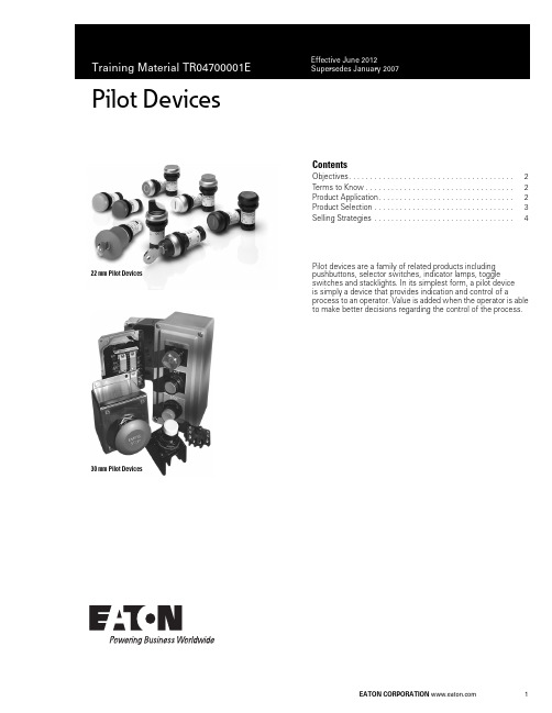
Pilot Devices1ContentsObjectives. . . . . . . . . . . . . . . . . . . . . . . . . . . . . . . . . . . . . . . 2Terms to Know . . . . . . . . . . . . . . . . . . . . . . . . . . . . . . . . . . . 2Product Application. . . . . . . . . . . . . . . . . . . . . . . . . . . . . . . . 2Product Selection . . . . . . . . . . . . . . . . . . . . . . . . . . . . . . . . . 3Selling Strategies . . . . . . . . . . . . . . . . . . . . . . . . . . . . . . . . .4Pilot devices are a family of related products including pushbuttons, selector switches, indicator lamps, toggle switches and stacklights. In its simplest form, a pilot device is simply a device that provides indication and control of aprocess to an operator. Value is added when the operator is able to make better decisions regarding the control of the process.22 mm Pilot Devices30 mm Pilot DevicesTraining Material TR04700001E Effective June 20122Pilot DevicesObjectives●Recognize opportunities●Develop solution with related components●Compete in the marketTerms to KnowThe following terms are used to describe application requirements common to industrial control systems. You should familiarize yourself with the meaning of these terms and the applications they describe.Pilot Device GlossaryProduct ApplicationPilot devices are available in many shapes and sizes based on their functionality and application. In general, devices are designed for application into two general markets: the IEC (global) market, and the NEMA (North American) market.The NEMA standard does not dictate function and appearance of pilot devices, but the standard does allow the use of industrial market segments to define such requirements.Note: The automotive market segment has adopted a RED “run” indicator standard in which red indicator lights illuminate when machinery is operating and represents a potentially unsafe condition.The IEC standard has adopted strict requirements concerning application of pilot devices. For example IEC 60204-1 requires pushbutton actuators be color-coded for universal application according to the format in the following table.IEC Color Coding Product developed for the IEC market is application-rated, requiring lighter duty-ratings than what the NEMA market requires. For this reason, product is typically 1/3 to 1/2 as expensive and is often positioned as a disposable commodity in the market. OEM customers appreciate the lower price, which reduces their burden cost that they typically pass on to the end-users.IEC standards 417-IEC-5007 and 417-IEC-5008 require START/STOP and ON/OFF controls be marked with universal symbols. Can you determine which symbol represents ON/START and which represents OFF/STOP?Term Definitioncontact The conducting part of a switch that operates with another conducting part to make or break a circuit contact block The part of a pushbutton that is activated when the operator is presseddebouncing The act of removing intermediate noise spikes from a mechanical switchdouble-break Contacts that break the electrical circuit in two placesdrum switch A manual switch consisting of moving contacts mounted on an insulated rotating shaftlatch An instruction or component that retains its state after a temporary condition occursOFF-delay A timing function that gains value when an input condition transitions from ON to OFFON-delay A timing function that gains value when an input condition transitions from OFF to ONone-shot (interval timer)A timing function that gains value when an input condition transitions from ON to OFF. Output state is maintained while timer is active.pole Number of isolated circuits in a switch devicerelay Device that controls one electrical circuit by manipulating contacts in another circuit throw Number of closed contact positions per poletransducer Device that converts physical parameters to electrical signalsColor Meaning Explanation ExamplesRed Emergency Actuate in the event of ahazardous condition oremergencyE-Stop, STOP/OFFYellow Abnormal Actuate in the event of anabnormal condition Intervention to suppress abnormal condition. Intervention to restart an interrupted automatic cycle.Green Normal Actuate to initiate normalconditionSTART/ONBlue Mandatory Actuate for a condition requiringmandatory actionReset FunctionWhite No specificmeaning assigned For general initiation of functionsexcept for emergency stopSTART/ON, STOP/OFFBlack No specificmeaning assigned For general initiation of functionsexcept for emergency stopSTART/ON, STOP/OFFPurpose:Purpose:Training Material TR04700001EEffective June 2012Pilot Devices 3Product SelectionVolume 7—Logic Control Operator Interface and Connectivity Solutions , CA08100008E, Tab 1 provides product selection tables for pushbuttons, selector switches, indicator lights, potentiometers, enclosures and related accessories. Stacklights and relatedaccessories are supported in Tab 2. The following sections provide an overview of the product groups.M22/C22 SeriesEaton M22/C22 industrial heavy-duty pushbutton lines offer a wide array of functional, attractive and ergonomically designed illuminated and non-illuminated pushbuttons, selector switches, push-pulls, alternate action and twist-to-release operators. M22 operators are available with either a silver or a black colored bezel.●22.5 mm mounting hole●M22 modular design allows customers to mix/match contact blocks and operators●C22 compact, all-in-one design gives customers a simple installation●NEMA 3R, 4X, 13 and IP67/69k on most operators ●100% LED technology throughout lines ●Fully custom laser etching available●Toolless secure assembly of mounting adapter and contact blocks ●Notched hole mounting with anti-rotation nib standard10250T SeriesThis family of pushbutton, selector switch, indicator light and potentiometer devices represents the flagship product for NEMA applications. It is easily recognized by its brilliant chrome finish.Features include:●30.5 mm mounting hole●Contact blocks feature “reliability nibs” that ensure long life and dependable switching despite oxidation and corrosion on the contact surfaces●Operators feature “grounding nibs” that ensure electrical grounding of the operator with the panel●UL 600 Vac rating, 10 million operations (mechanical), 1million (electrical)●NEMA 1/2/3/3R/4/4X/12/13 and IEC IP65 ratingsBenefits include:●New contact block design provides greater visibility with laser-engraved terminal markings and light gray material. Ultrasonic welding of contact blocks have been eliminated, making the components acceptable for low emissivity ratings required by IEC and other global market standardsE34 SeriesThe E34 family of pilot device products represents the ultimate in corrosion-resistant packaging of pilot devices. It uses the same design elements of the 10250T, but replaces the brilliant chrome finish with a triple-layer epoxy finish that is extremely durable.Features include:●Uses the same contact block, operator mounting, and accessories as the 10250T●Meets NSF requirements for corrosion resistance fromcontinuous salt spray for 200 hours. Tested to 600 hours before visible corrosion appearsBenefits include:●OEMs and panelshops may appreciate the distinctive appearance of their panels provided by the black epoxy coatings of the E34 devicesHT800 SeriesThis family of pushbuttons, selector switches, indicator lights and related accessories was developed in response to the need for a family of products that provide basic functionality at a low price without sacrificing the appearance of a panel that may contain competitive products.Features include:●30.5 mm mounting hole●Transparent contact blocks that mount two-across and interlock to prevent separation due to wiring harness stress●Contact blocks may be mounted in Left/Right or Top/Bottom positions to accommodate a variety of wiring layouts●Reduced product variation expedites delivery/setup/inventoryBenefits include:●Lower cost product with basic functionality for customers who don’t need advanced featuresE30 SeriesDo you have customers that have outgrown their control panels? This situation is obvious to anyone that walks through a facility and observes pilot devices mounted to the tops, sides and back ofexisting control panels. If so, the E30family of products provides an elegant solution by integrating the function of pushbutton and indicating light into a single operator.Features include:●30.5 mm mounting hole●Up to six operations in one package●Selector switch and potentiometer designs also available●Unique contact block locking mechanism provides easy removal of contacts without disturbing the panel-mounted operators ●Customized legends/lensesBenefits include:●This product is well-positioned for applications requiring minimal panel spaceC22M22Training Material TR04700001EEffective June 2012Pilot DevicesEaton is a registered trademark of Eaton Corporation.All other trademarks are property of their respective owners.Eaton Corporation Electrical Sector 1111 Superior Ave.Cleveland, OH 44114United States © 2012 Eaton Corporation All Rights Reserved Printed in USAPublication No. June 2012 / Z12416TR04700001EE10 Toggle SwitchesOEMs that supply equipment to commercial, retail and light industrial operations may find the E10 family of selector switches and plunger toggle switches to be an ideal solution for light-duty switching of resistive and inductive loads.Features include:●0.468 in mounting hole●Packaged in quantities of 10●1–4 poles, single and double throwBenefits include:●These operators make idealcompanions to much larger industrial switches when secondary control is required for remote operationE26 StacklightsConcerned with visibility of indicator lights, or perhaps you’d like to add audible alarms to a control panel? If so, the E26 series of stacklight products provides the solution in the most demanding environments.Features include:●Modular design allows customized appearance of colors and blink rates (clear, red, yellow, green, blue, amber)●Supports monotone, bitone, and intermittent audible alarming●Incandescent, LED or xenon strobe lampsBenefits include:●The lamps are designed to interact with a wide range of control signals, from 12 to 240V . Mounting isaccommodated through a variety of bases, including 3/4 in NPT , 3- or 4-hole designsSelection SummaryThe following table provides general guidelines for application of the various pushbutton, selector switch and indicator light products.Product ApplicationsSelling StrategiesEaton has a comprehensive selection of IEC and NEMA pilot devices as open components or assembled in packages for enclosed and MCC. Selection —Eaton provides complementary product lines in addition to the basic pilot devices. These products include metallic and nonmetallic enclosures, signal conditioning and isolation transformers, sensors and programmable controls.Customization —Warehouses in Spartanburg, SC, and Memphis, TN, support customized labeling of legend plates and lenses for all pilot devices. Order forms are included in the catalog.Ease of Installation —No tools are required for the IEC rated devices and modular assemblies support the installation of operators separate from the contact blocks for the NEMA rated devices. Products may be ordered fully assembled or as separate components.How do Eaton’s products compete ? Reinforce the capability of the 48 hour mod center, our warehouse stocking, ProShop training, regional service centers and faster delivery.ServiceNote1The E34 family of devices is sensitive to UV light when applied in outdoor applications. The devices will appear slightly discolored after long periods of exposure to direct sunlight. The functionality ofthe device is not affected.IndoorOutdoor Washdown Corrosive Explosive 10250T Yes Yes Yes No Yes HT800Yes No Yes No No E34Yes Yes 1Yes Yes Yes E30Yes No No No No M22Yes Yes Yes Yes No C22YesYesYesYesNoResourcesValue AddManufacturing Facilities(Chicago, Denver, Los Angeles, Hartford, Houston)Regional support for entire product line. Open to customer visits. Able to ship quickly. Warehouses Provide balance for distributor stocking ProShops Distributor support provides ownership of solutionMod CenterFlexibility of solutions。
美国电器公司Eaton PDG21G0040TFFL型号产品说明说明书
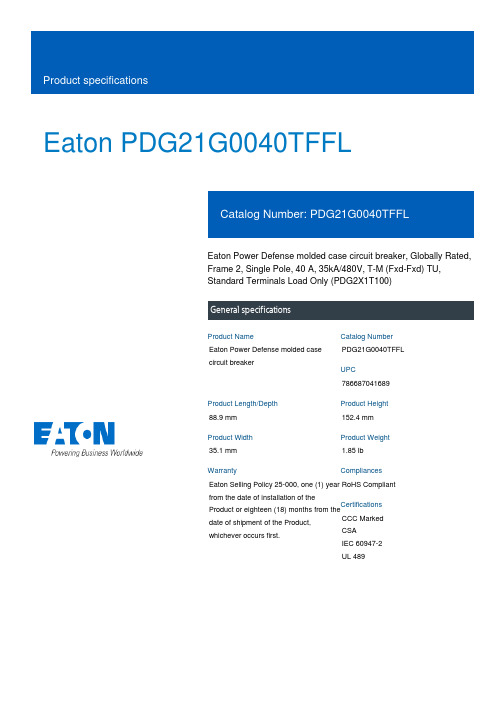
Eaton PDG21G0040TFFLEaton Power Defense molded case circuit breaker, Globally Rated, Frame 2, Single Pole, 40 A, 35kA/480V, T-M (Fxd-Fxd) TU, Standard Terminals Load Only (PDG2X1T100)Eaton Power Defense molded case circuit breakerPDG21G0040TFFL 78668704168988.9 mm 152.4 mm 35.1 mm 1.85 lb Eaton Selling Policy 25-000, one (1) year from the date of installation of theProduct or eighteen (18) months from thedate of shipment of the Product,whichever occurs first.RoHS Compliant CCC MarkedCSAIEC 60947-2UL 489Product NameCatalog Number UPCProduct Length/Depth Product Height Product Width Product Weight WarrantyCompliancesCertifications35 kAIC at 480 Vac260040 ASingle-pole600 VPD2 Global20 kAIC Icu/ 15/13 kAIC Ics/ 42 kAIC Icm @525V South Africa (IEC)65 kAIC @240V (UL)8 kAIC Icu/ 4 kAIC Ics/ 16.8 kAIC Icm @690V (IEC)10 kAIC Icu @125 Vdc18 kAIC @600V (UL/CSA)25 kAIC Icu/ 20 kAIC Ics/ 52.5 kAIC Icm @480V Brazil (IEC) 30 kAIC Icu/ 22.5 kAIC Ics/ 63 kAIC Icm @440V (IEC)35 kAIC @480V (UL)36 kAIC Icu/ 36 kAIC Ics/ 75.6 kAIC Icm @380-415V (IEC)10 kAIC Icu @250 Vdc55 kAIC Icu/ 55 kAIC Ics/ 121 kAIC Icm @240V (IEC) ThermomagneticClass AComplete breakerStandard Terminals Load Only600 Vac Eaton Power Defense PDG21G0040TFFL 3D drawingConsulting application guide - molded case circuit breakersPower Defense molded case circuit breaker selection posterPower Defense brochurePower Defense technical selling bookletPower Defense molded case circuit breakers - Frame 2 product aid Molded case circuit breakers catalogPDG4 CCC certificationPDG4 CB reportEU Declaration of Conformity - Power Defense molded case circuit breakersPDG2 CB reportPower Defense Declaration concerning California’s Proposition 65Power Defense Frame 2 tunnel terminal (aluminum), 50A, 1 pole instructions - IL012236EN H01Power Defense Frame 2 box terminal (aluminum), 225A, 1 pole instructions - IL012235EN H01Power Defense Frame 2 PDG2 and PDC(E)9 breaker instructions -IL012106ENPower Defense Frame 2 tunnel terminal kits - PDG2X1TA225K instructions- IL012239EN H01Power Defense Frame 2/3/4/5/6 voltage neutral sensor module wiring instructions – IL012316ENPower Defense Frame 2 locking devices and handle block instructions - IL012149ENPower Defense Frame 2 box terminal (steel), 100A, 1 pole instructions - IL012234EN H01Power Defense Frame 2 tunnel terminal (aluminum), 100A, 1 pole instructions - IL012237EN H01Power Defense Frame 1-2-3-4 IP door barrier assembly instructions - IL012278ENPower Defense Frame 2 tunnel terminal (aluminum), 150A, 1 poleInterrupt ratingFrameRated operation voltage (Ue) at AC - max Amperage RatingNumber of polesVoltage rating - maxCircuit breaker typeInterrupt rating rangeSwitch off techniqueClassCircuit breaker frame typeTerminalsVoltage rating 3D CAD drawing package Application notes BrochuresCatalogsCertification reports Installation instructionsEaton Corporation plc Eaton House30 Pembroke Road Dublin 4, Ireland © 2023 Eaton. All Rights Eaton is a registered trademark. All other trademarks areproperty of their respectiveT-M (Fxd-Fxd) TU instructions- IL012238EN H01Power Defense Frame 2 clamp terminal (steel), 20A, 1 pole instructions- IL012246EN H01Power Defense Frame 2 TMTU Aux, Alarm, ST and UVR Animated Instructions.rhPower Defense Frame 2 withTMTU, Shunt Trip_UVR Animated Instructions.rhPower Defense Frame 3 Variable Depth Rotary Handle Mechanism Installation How-To VideoEaton Power Defense for superior arc flash safetyPower Defense molded case circuit breakersPower Defense Frame 2 Variable Depth Rotary Handle Mechanism Installation How-To VideoPower Defense Frame 6 Trip Unit How-To VideoPower Defense BreakersPower Defense Frame 5 Trip Unit How-To VideoEaton Specification Sheet - PDG21G0040TFFLPower Defense time current curve Frame 2 - PD2Intelligent circuit protection yields space savingsMaking a better machineSingle and double break MCCB performance revisitedMolded case and low-voltage power circuit breaker healthMolded case and low-voltage breaker healthSafer by design: arc energy reduction techniquesTrip TypeInstallation videosMultimediaSpecifications and datasheetsTime/current curvesWhite papersReserved.owners./socialmedia。
电动控制设备Eaton XXCFXXX30-RJ的操作手册说明书

ContentsDescription Page 1.0 Setup ................................21.1 Before Installation .....................21.2 Installation ..........................21.2.1 DIN Rail Kits ......................21.3 Wiring ..............................21.3.1 Series Wiring Applications ...........31.3.2 Parallel Wiring Applications ..........31.3.3 Dry Contact Wiring .................31.3.4 Telephone Line Protection ...........31.4 Apply Power .........................3 1.5 Specifications ........................41.6 Warranty . (4)nstallation Instructions for EatonSurge Protective Device XXCFXXX30-RJ2Instruction Manual IM01005027E Rev. 4Effective October 2018Installation Instructions for EatonSurge Protective Device XXCFXXX30-RJEATON WARNINGHAZARDOUS VOLTAGES PRESENTIMPROPER INSTALLATION OR MISAPPLICATION OF THESE DEVICES MAY RESULT IN SERIOUS INJURY TO INSTALLER AND/OR DAMAGE TO ELECTRI-CAL SYSTEM OR RELATED EQUIPMENT. READ AND UNDERSTAND ALL INSTRUCTIONS BEFORE BEGINNING INSTALLATION. PROTECTIVE EYE-WEAR SHOULD BE WORN WHENEVER WORKING AROUND HAZARDOUS VOLTAGES.NOTICEALL INSTRUCTIONS AND MEASUREMENTS MUST BE COMPLETED BY A LICENSED/QUALIFIED ELECTRICIAN IN ACCORDANCE WITH THE U.S. NATIONAL ELECTRICAL CODE, STATE AND LOCAL CODES OR OTHER APPLI-CABLE COUNTRY CODES. THE U.S. NATIONAL ELECTRICAL CODE AND STATE AND LOCAL REQUIREMENTS (OR OTHER APPLICABLE COUNTRY CODES) SUPERSEDE THIS INSTRUCTION.Catalog NumberVoltage RangeModeVPRMCOVInSCCRPeak Surge CurrentXXCF12030-RJ 248 - 149 Vdc 1 100 -127 Vac L-N L-G N-G 5005005001501501505kA 10kA 80kAXXCF23030-RJ 2150 - 300 Vdc 1128 - 230 VacL-N, L-G, N-G8008008002752752753kA 10kA 80kA1 UL 1449 4rd Edition does not list SPD products rated less than 110 Vac or DC voltages.2UL 1449 4th Edition, UL 1283 7th Edition1.0 SetupVerify that system voltages do not exceed those listed in Section 1.5, Specifications. • All AC measurements should be completed with an RMS voltme-ter.• All DC measurements should be completed with a DC voltmeter.•DO NOT INSTALL FILTER IF MEASURED VOLTAGE EXCEEDSMAXIMUM OPERATING LIMITS.Choose location for filter installation so that maximum separation can be maintained between input leads, output leads and ground leads.1.1 Before InstallationREMOVE POWER FROM ELECTRICAL SYSTEM BEFORE MOUNTING FILTER.•Filter MUST be mounted within enclosure to assure personnel safety from exposed terminals.IMPORTANT:FILTER SHOULD BE LOCATED SO THAT THE SHORTEST POSSIBLE CONDUC-TOR LENGTH MAY BE USED.•Filter should be mounted to allow maximum separation between input and output wiring.•Filter contains no position-oriented components and can be mounted upside down or sideways.•Filter should be placed in electrical circuit so that it is the last device in the circuit before equipment to be protected.1.2 InstallationFILTER MUST BE CONNECTED TO ELECTRICAL SYSTEM WITH A CIRCUIT BREAKER:For AC Applications•1 – Single Pole / Single Throw 40A circuit breaker(s). The Interrupting Rating of the Circuit Breaker Shall Not Be LessThan the Available Fault Current. Circuit Breaker Ratings of 40A, 240V/415V, 10kA Min. AIC Rating.ote:N Pre-existing breaker(s) of the rated load size may be utilized if provi-sion for multi-conductor connections are made according to N.E.C. 110-14A.•If Neutral wire is to be utilized as L2/NEU then circuit breaker should be provided for that phase.For DC Applications•DC units to be installed after an overcurrent protective device that is rated not to exceed 100% of the current rating of the unit.•Form C contacts are rated at 0.5 Amps at 125 VAC or 1.0 Amps at 30 VDC. These connections are to be used for alarm hook up.T able 1. Relay state when energized.Catalog Part NumberNormally ClosedNormally OpenXXCFXXX30-RJ Open ClosedREMOVE POWER FROM ELECTRICAL SYSTEM BEFORE INSTALLING FILTER.Mechanically mount filter.•Mount filter using mounting flange holes or optional DIN bracket listed below.•Filter should be mounted to allow maximum separation between input and output wiring.•Filter contains no position oriented components and can be mount-ed upside down or sideways.•Filter should be placed in electrical circuit so that it is the last device in circuit before equipment to be protected.1.2.1 DIN Rail Kits Mounting bracket and foot adaptable to DIN Rail systems DIN EN 50022, DIN EN 50035 and DIN EN 50045 are available through Eaton Order Center and can be ordered separately.• Eaton Cat# DINRAILKIT-30ACF•Eaton Innovative Technology Cat# DINRAILKIT-30ITCF1.3 WiringNOTICEAN INSULATED GROUNDING CONDUCTOR THAT IS IDENTICAL IN SIZE AND INSULATION MATERIAL AND THICKNESS TO THE GROUNDED AND UNGROUNDED CIRCUIT SUPPLY CONDUCTORS, EXCEPT THAT IT IS GREEN WITH OR WITHOUT ONE OR MORE YELLOW STRIPES, IS TO BE INSTALLED AS PART OF THE CIRCUIT THAT SUPPLIES THE FILTER. SEE TABLE 250-122 OF THE NATIONAL ELECTRIC CODE (NEC) REGARDING THE APPROPRIATE SIZE OF THE GROUNDING CONDUCTOR.THE GROUNDING CONDUCTOR IS TO BE GROUNDED TO EARTH AT THE SERVICE EQUIPMENT OR OTHER ACCEPTABLE BUILDING EARTH GROUND SUCH AS THE BUILDING FRAME IN THE CASE OF HIGH-RISE STEEL FRAME STRUCTURE.ANY ATTACHMENT-PLUG RECEPTACLES IN THE VICINITY OF THE FILTER ARE TO BE GROUNDING TYPE, AND THE GROUNDING CONDUCTORS SERV-ING THESE RECEPTACLES ARE TO BE CONNECTED TO EARTH GROUND AT THE SERVICE EQUIPMENT OR OTHER ACCEPTABLE BUILDING EARTH GROUND SUCH AS THE BUILDING FRAME IN THE CASE OF HIGH-RISE STEEL FRAME STRUCTURE.PRESSURE TERMINAL OR PRESSURE SPLICING CONNECTORS AND SOL-DERING LUGS USED IN THE INSTALLATION OF THE FILTER SHALL BEIDENTIFIED AS BEING SUITABLE FOR THE MATERIAL OF THE CONDUCTORS. CONDUCTORS OF DISSIMILAR METALS SHALL NOT BE INTERMIXED IN A TERMINAL OR SPLICING CONNECTOR WHERE PHYSICAL CONTACT OCCURS BETWEEN DISSIMILAR CONDUCTORS UNLESS THE DEVICE IS IDENTIFIED FOR THE PURPOSE AND CONDITIONS OF USE.CONDUCTORS SHOULD BE TWISTED TOGETHER TO REDUCE IMPEDANCE FACTOR. EXCESSIVE WIRE LENGTH AND SHARP BENDS DEGRADE FILTER PERFORMANCE; THEREFORE, AVOID EXCESSIVE WIRE LENGTH AND SHARP BENDS.3Instruction Manual IM01005027E Rev. 4Effective October 2018Installation Instructions for EatonSurge Protective Device XXCFXXX30-RJEATON Table of Maximum Suggested Operating UnitsModel Number Power ProtectionData ProtectionLine to Neutral (MCOV)Line to Ground (MCOV)Neutral to Ground* (MCOV)Maximum All Modes (@60 Hz) Amps Pins Peak Voltage L-L, L-G Max. Continuous Operating Current (mA)Max. Data Rate (Mbps)XXCF12030-RJ 150150150401-4, 2-31341001XXCF23030-RJ27527527540*Note: If Neutral to Ground voltage is greater than 5 VAC then a problem may exist in electrical system. Filter may be installed; however, a qualified person should be consulted to correct problem.1.3.1 Series Wiring Applications•Connect incoming system GROUND wire to terminal labeledGND on unprotected end (labeled as LINE ).•Connect load side GROUND wire to terminal labeled GND on protected end (labeled as EQUIP ).For AC Applications•Connect incoming system NEUTRAL wire to terminal labeled L2/NEU on unprotected end (labeled as LINE ).•Connect load side NEUTRAL wire to terminal labeled as L2/NEU on protected end (labeled as EQUIP ).•Connect incoming system HOT wire to terminal labeled L1 on unprotected end (labeled as LINE ).•Connect load side HOT wire to terminal labeled as L1 on protected end (labeled as EQUIP ).For DC Applications•Connect incoming system NEGATIVE wire to terminal labeled L2/NEU on unprotected end (labeled as LINE ).•Connect incoming system POSITIVE wire to terminal labeled L1 on unprotected end (labeled as LINE ).1.3.2 Parallel Wiring ApplicationsIMPORTANT:FILTER SHOULD BE LOCATED SO THAT THE SHORTEST POSSIBLE CON-DUCTOR LENGTH MAY BE USED. CONDUCTORS SHOULD BE TWISTED TOGETHER TO REDUCE IMPEDANCE FACTOR. EXCESSIVE WIRE LENGTH AND SHARP BENDS DEGRADE FILTER PERFORMANCE; THEREFORE, AVOID EXCESSIVE WIRE LENGTH AND SHARP BENDS.•Connect incoming system GROUND wire to terminal labeled GND on unprotected end (labeled as LINE ).For AC Applications•Connect incoming system NEUTRAL wire to terminal labeled L2/NEU on unprotected end (labeled as LINE ).•Connect incoming system HOT wire to terminal labeled L1 on unprotected end (labeled as LINE ).For DC Applications•Connect incoming system NEGATIVE wire to terminal labeled L2/NEU on unprotected end (labeled as LINE ).•Connect incoming system POSITIVE wire to terminal labeled L1 on unprotected end (labeled as LINE ).ote:N For grounded or isolated control transformer secondary, DO NOT CONNECT Ground terminal on either LINE or EQUIP side.1.3.3 Dry Contact WiringConnect ALARM leads to Normally Open (N/O) or Normally Closed (N/C) terminals as required.1.3.4 Telephone Line ProtectionConnecting telephone line to protection.•Assemble RJ-14 modular plugs to LINE and EQUIP telephone cables.•Connect circuit as follows: Circuit 1 = Pins 2 and 3; Circuit 2 = Pins 1 and 4.• Insert modular plugs into LINE and EQUIP modular jacks.•Assure that telephone circuits are operational.ote:N For ungrounded or isolated control transformer secondary, DO NOT CONNECT Ground terminal on either LINE or EQUIP side.1.4 Apply PowerApply power to system. Indicator light(s) should glow and alarm contacts should move to normal state. If the light(s) does not glow, remove power and contact supplier.Instruction Manual IM01005027E Rev. 4 Effective October 2018Installation Instructions for Eaton Surge Protective Device XXCFXXX30-RJEatonElectrical Sector1000 Eaton Boulevard Cleveland, OH 44122United States877-ETN-CARE (877-386-2273) © 2018 EatonAll Rights ReservedPrinted in USAPublication No. IM01005027E / TBG000473 October 2018Eaton is a registered trademark.All other trademarks are property of their respective owners.Agency ApprovalsXXCFXXX30-RJ UL1449 4th Edition, UL1283 7th Edition Type 2 SPDTerminal Connections Wire clamping terminals, 10-18 AWG (UL), 10-22 AWG (CSA)Torque 12 in-lbOperating Temperature-40F(-40C) to +140F(+60C)System voltagesDC48 - 149 Vdc, 150 - 300 VdcAC100 - 127 Vac, 128 - 230 VacCircuit Breaker40A, 240V/415V, 10kA Min. AIC Rating(Eaton P/N:FAZ-C40/1-NA-SP)Amps*30Input Power Frequency50/60 HzWarranty 5 Years, 10 Years if registered on /spd RoHS Compliant Yes* Amp rating is for series connection only. Parallel connection is not current dependent.Purchaser’s right under the warranty shall consist solely of requiring Eaton to repair, or at Eaton’s sole discretion, replace, free of charge, F.O.B. factory, and defective items received at said factory or failure to give any advice or recommendations by Eaton shall not constitute any warranty by or impose any liability upon Eaton. The foregoing constitutes the sole and exclusive liability of Eaton AND IS IN LIEU OF ANY AND ALL OTHER WARRANTIES EXPRESSED, IMPLIED OR STATUTORY AS TO THE MERCHANTABILITY, FITNESS FOR PURPOSE SOLD, DESCRIPTION, QUALITY, PRODUCTIVENESS OR ANY OTHER MATTER.In no event shall Eaton be liable for special or consequential dam-ages or for delay in performance of the warranty.This warranty does not apply if the prod1uct has been misused, abused, altered, tampered with, or used in applications other than specified on the nameplate. At the end of the warranty period, Eaton shall be under no further warranty obliga-tion expressed or implied.The product covered by this warranty certificate can only be repaired or replaced by the factory. For help on troubleshooting the Critical Protection Product, or for warranty information, call 1-800-809-2772, Option 4, sub-option 2. Repair or replacement units will be returned collect. If Eaton finds the return to be a manufacturer’s defect, the product will be returned prepaid.。
Eaton I.T. Protector技术数据手册说明书

Eaton Innovative TechnologyI.T. ProtectorContentsDescription PageProduct application . . . . . . . . . . . . . . . . . . . . . . . . . . . . . . . . . . . . . . . . . . . . . . . . . . . . . . . . . . . . . . . . . . .2General description . . . . . . . . . . . . . . . . . . . . . . . . . . . . . . . . . . . . . . . . . . . . . . . . . . . . . . . . . . . . . . . . . . .2Features, functions, and benefits . . . . . . . . . . . . . . . . . . . . . . . . . . . . . . . . . . . . . . . . . . . . . . . . . . . . . . . .2Optional features . . . . . . . . . . . . . . . . . . . . . . . . . . . . . . . . . . . . . . . . . . . . . . . . . . . . . . . . . . . . . . . . . . . . .2S .M .A .R .T . diagnostics . . . . . . . . . . . . . . . . . . . . . . . . . . . . . . . . . . . . . . . . . . . . . . . . . . . . . . . . . . . . . . . . .3Standards and certifications . . . . . . . . . . . . . . . . . . . . . . . . . . . . . . . . . . . . . . . . . . . . . . . . . . . . . . . . . . . .3Product specification . . . . . . . . . . . . . . . . . . . . . . . . . . . . . . . . . . . . . . . . . . . . . . . . . . . . . . . . . . . . . . . . . .3Standard I .T . Protector product selection . . . . . . . . . . . . . . . . . . . . . . . . . . . . . . . . . . . . . . . . . . . . . . . . . .4Standard I .T . Protector standard dimensions—inches (mm) . . . . . . . . . . . . . . . . . . . . . . . . . . . . . . . . . . . .4Legacy I .T . Protector product selection . . . . . . . . . . . . . . . . . . . . . . . . . . . . . . . . . . . . . . . . . . . . . . . . . . . .7Legacy I .T . Protector standard dimensions—inches (mm) . . . . . . . . . . . . . . . . . . . . . . . . . . . . . . . . . . . . .72Technical Data TD01006002EEffective April 2023Eaton Innovative T echnologyI.T . ProtectorEATON Product applicationEaton’s Innovative T echnology T I .T . Protector E surge protective device (SPD) protects electronic equipment from damaging transients . The I .T . Protector is suitable for high, medium and low exposure levels, and sensitive mission-critical load applications including:• Switchboards/main panels • Distribution panels • Branch panels • Critical loadcenters • Dedicated load protection • Variable frequency drives (VFDs)•Motor protectionGeneral descriptionSince 1980, Eaton has been designing and producing SPDs thatprovide field-proven power quality solutions worldwide . The Protector is a rugged device that is easy to install adjacent or even internal to electrical equipment . Based on extensive proven field performance, Eaton was the first to offer a 20-year full replacement warranty for the Protector . Electrical engineers around the world recognize Eaton as a leader in the SPD industry . A leading research company in a survey of over 10,000 users rated Eaton No . 1 in both product quality and service . Protector products are listed to UL T 14495th Edition and have a complementary UL 1283 7th Edition listing . All of Eaton’s Innovative Technology products are manufactured in an ISO T 9001:2000 and ISO 14001 certified facility .Features, functions, and benefits•Advanced surge path technology for high fault current capacity, low impedance, high frequency design•Encapsulation technology provides a high dielectric and ultimate protection from adverse environmental conditions • Industry-best nominal discharge current (I n ) of 20 kA • Rugged NEMA T Type 4 (IP66) powder-coated steel enclosure •Large diameter metal oxide varistors provide long life under high stress transient environments• Dry Form C contacts for remote s tatus monitoring • LED monitoring on each phase• Wide range of voltage applications from 120 to 600 Vac •20-year free replacement warranty with registrationOptional features•NEMA Type 4X stainless-steel enclosure provides unparalleled corrosion protection and environmental strength for the most adverse installation conditions•Enhanced filtering, Active Tracking Network T (ATN) provides the best in transient protection against the continuous barrage of everyday transients; this filter is also UL 1283 7th Edition listed as an EMI/RFI filter•Available integral circuit breaker and disconnect switch for convenient installation and maintenance•Available integral circuit breaker for installations requiring no external overcurrent protection•S .M .A .R .T .E diagnostics provide state-of-the-art diagnostics in the form of a digital surge event counter and audible alarm in conjunction with the standard status indicator lamps •Available flushmount for recessed installations3Technical Data TD01006002EEffective April 2023Eaton Innovative T echnology I.T . Protector EATON S .M .A .R .T . diagnostics panelS.M.A.R.T . diagnostics• Comprehensive monitoring of critical system functions•Real-time audible and visual reporting of unit status, phase loss/protection loss, and transient events (alarm with reset and mute)•Records low, medium, and high surge events in approximateaccordance with ANSI C62 .41-1991, Type A, B, and C surge levels •Dual-function surge counter provides non-volatile event history recordingStandards and certifications•UL 1449 5th Edition and UL 1283 7th Edition listed surge protective devices (SPD)• CE marked (PTX/E048, PTX/E065, PTX/E080, PTX160)•All Eaton’s Innovative Technology Protector units have been tested as per NEMA LS-1 and ANSI/IEEE T C62 .45• Can be used for UL 96A compliance • Can be used for NFPA T 780 compliance •Can be used for RoHS complianceProduct specificationT able 1. Protector series specificationsDescriptionSpecificationkA per phase 48, 50, 65, 80, 100, 120, 160, 200, 240, 300, 400kA per mode24 to 200Nominal discharge current (I n )20 kA (Models 120, 160, 240, 300 and 400 kA per phase) 10 kA (Models 48, 65 and 80 kA per phase)Protection modes Wye system: L-L, L-N, L-G and N-G / delta system: L-L, L-G Split-phase system: L-L, L-N, L-G and N-GWye system voltages100/175, 110/190, 120/208, 127/220, 220/380, 230/400, 240/415, 277/480, 305/525, 347/600Delta system voltages 200, 208, 220, 230, 240, 380, 400, 415, 440, 480, 525, 600Split-phase voltages 100/200, 110/220, 120/240, 127/254Single-phase voltages100, 110, 120, 127, 200, 208, 220, 230, 240, 277ote: N U .S . voltages in bold .T able 2. Protector let-through voltage ratingsRatingsL-LL-GL-NN-GDelta systemL-LL-GANSI IEEE Cat A1120/240 V; 120/208 V wye; 240 V delta90100606070590277/480 V wye; 480 V delta 1001207070601100347/600 V wye; 600 V delta901207070401100ANSI IEEE Cat C3120/240 V; 120/208 V wye; 240 V delta1240100083089012601420277/480 V wye; 480 V delta 206015801370137021202130347/600 V wye; 600 V delta257018801680170026702640ANSI IEEE Cat B3/C1120/240 V; 120/208 V wye; 240 V delta900550520520860850277/480 V wye; 480 V delta 1640105098094019901840347/600 V wye; 600 V delta 211013201250121020902040UL 1449, 5th Edition voltage protection rating120/240 V, 120/208 V wye; 240 V delta100060060060010001000277/480 V wye, 480 V delta 200012001200120020001800347/600 V wye, 600 V delta250015001500150025002500ote: N All tests performed with 6-inch lead length, positive polarity . Voltages are peak ±10% . All measurements are taken from the zero reference per NEMA LS-1 .ote: N Let-through voltage figures shown are for selected models and vary per Protector model . See individual submittal specification sheets for specificlet-through voltage measurements .4Technical Data TD01006002EEffective April 2023Eaton Innovative T echnologyI.T . ProtectorEATON Standard I.T . Protector product selectionT able 3. Standard I.T . Protector catalog numbering systemStandard I.T. Protector standard dimensions—inches (mm)Figure 1. PTE050, 080, 100 (-NL) and (-NS) models and PTX100 (-NL) and (-NS) models5Technical Data TD01006002EEffective April 2023Eaton Innovative T echnology I.T . Protector EATON Figure 2. Protector series for PTE120, 160, 200 (-NL) and (-NS) models and PTX120, 160, 200 (-NL) and (-NS) modelsFigure 3. FLUSHMNTPLATE15 PTE units 050, 080, and 100 kA and PTX 100 kA6Technical Data TD01006002EEffective April 2023Eaton Innovative T echnologyI.T . ProtectorEATON Figure 4. FLUSHMNTPLATE16 PTE/X units 120, 160, 200 kA7Technical Data TD01006002EEffective April 2023Eaton Innovative T echnology I.T . Protector EATON Legacy I.T . Protector product selectionT able 4. Legacy I.T . Protector catalog numbering systemLegacy I.T . Protector standard dimensions—inches (mm)Figure 5. Protector series for PTX048, 065, 080 all models8Technical Data TD01006002EEffective April 2023Eaton Innovative T echnologyI.T . ProtectorEATON Figure 6. Protector series for PTX240 medium-voltage models onlyFigure 7. Protector series for PTE/PTX240 low-voltage models, PTE/PTX300 all models and PTE/PTX400, all models9Technical Data TD01006002EEffective April 2023Eaton Innovative T echnology I.T . Protector EATON Figure 8. Protector series for integral circuit breaker (-C) and circuit breaker and external disconnects (-CD) 80, 120 a , 160, 240 a and 300 kA modelsa Available only in low-voltage units.Figure 9. Protector series for integral circuit breaker (-C) and circuit breaker and external disconnect (-CD) 400 kA models10Technical Data TD01006002EEffective April 2023Eaton Innovative T echnologyI.T . ProtectorEATON Figure 10. FLUSHMNTPLATE3A PTX units 48, 65, 80 kA11Technical Data TD01006002EEffective April 2023Eaton Innovative T echnology I.T . Protector EATON Eaton1000 Eaton Boulevard Cleveland, OH 44122 United StatesEaton .com© 2023 EatonAll Rights ReservedPrinted in USAPublication No . TD01006002E / Z27488 April 2023Eaton is a registered trademark.All other trademarks are propertyof their respective owners.Eaton Innovative T echnologyI.T. ProtectorTechnical Data TD01006002E Effective April 2023。
Eaton精密空调用户手册

身为多元化的动力管理专家,伊顿重视在中国的长期承诺和社会责任,一直以来都将可持续发展战 略身体力行,积极推动绿色产品和技术创新,并与国内产业紧密合作,为本土客户提供更有效的动 力管理方案。靠性精密空调降低操作成本高可靠性源于精密的气温调控高效可靠全年不间断运行有别于舒适性空调精密空调机组针对全年365天不间断的高效可靠运行而设计产品性能特点4伊頓sac精密空调产品性能特点ac直联风机风量可调节ac外转子直联风机比起皮带风机具有诸多好处200v6700m3h20paesp240v7400m3h20paesp280v8000m3h20paesp320v8400m3h20paesp360v8700m3h20paesp400v9000m3h20paesp7400m3h300paesp7400m3h20paesp7400m3h130paesp7400m3h200paesp7400m3h260paespexample
目录
目录 Index
伊顿公司介绍
公司介绍 .......................................................................................................................................................................... 1 伊顿在中国 ...................................................................................................................................................................... 1 伊頓公司节能环保介绍 .................................................................................................................................................... 1
伊顿产品速查手册V4

伊顿产品速查手册册 Eaton product
quick reference brochure
1
本手册为客户提供了 伊顿数据中心整体解决方案、典型应 用场景及推荐的 UPS 产品、Eaton 各系列 UPS、配电、 制冷、机柜产品 的优势介绍、主要参数,同时提供了常见问题的
回复术语和相关计算指导,使用者可以通过该手册快速查找到伊顿产 在不同行业的推荐应用方案,并根据产品特性及参数有针对性的进 行快速选型。 希望能够通过使用此速查手册,快速提升产品的拓展和应用能力。
热风 Eaton STS
DX RT 6K + 电池箱
冷风
解决方案组件
电源 ● DX RT ● 5PX ● 9PX
配电 ● STS ● ePDU
6
机柜 ● E系列机柜
美国电力公司(Eaton)产品说明说明书

2FApplications:Cast device boxes are installed to:• Accommodate wiring devices• Act as pull boxes for conductors in a conduit system• Provide openings to make splices and taps in conductors• Provide access to conductors formaintenance and future system changes • Connect conduit sections• FSY boxes for mounting surface devices on floor or bench (used with single-gang covers)Features:• Internal green ground screw standard on boxes• Suitable for use in wet locations when used with gasketed covers• Mounting lugs standard on most boxes • Tapered threaded hubs (NPT) with integral bushing• Available for surface mounting (withmounting lugs) or flush mounting (without mounting lugs) as listed• Available as shallow (FS) or deep (FD) configuration; use FD if device to be enclosed exceeds 15/8” in depth• Ample wiring room provided in either FS or FD configuration• Wide selection of surface or flush covers available in three materials (sheet steel, Feraloy, aluminum)• Covers for flush mounting extend to conceal the rough plaster line• Available in single-gang and multi-gang configurations with hubs, and as blank bodies for drilled and tapped openingsStandard materials:• Feraloy iron alloy or copper-free aluminumStandard finishes:• Feraloy – electrogalvanized and aluminum acrylic paint• Aluminum – naturalSize ranges:• Hubs – 1/2” to 1”Certifications and compliances:• UL standard: UL514A • ANSI standard: C33.84• Fed. Spec.: W-C-5860• CSA standard: C22.2 No. 18FS/FDCDie cast aluminumDWith and without mounting lugs for threaded rigid and IMC conduitCondulet FS and FD single-gangdevice boxes – cast iron or aluminumOptions:Description Suffix • Corro-free epoxy powder coat,external ..............................................S752• Corro-free epoxy powder coat,internal and external ..........................S753• Hot dip galvanized .............................HDGOrdering information:Hub sizeCat. #Cat. #1/“A B 1”FS3BFD3BA Available in sand cast copper-free aluminum. To order, add suffix ‘SCA’ to end of catalog number.B Available in copper-free aluminum. To order, add suffix ‘SA’ to end of catalog number.C Compatible with select hinged and open front control station covers in Section 4C.D Mounting lugs and ground screw are not offered with standard die cast aluminum box. For sand cast aluminum box with mounting lugs and ground screw, change ‘SA’ in catalog numberto ‘SCA.’ For example: FS1 SCA.FSR/FDR Hub sizeCat. #Cat. #1/“FSR1FDR1FSC/FDC CHub sizeCat. #Cat. #1/“AB 1”FSC3BFDC3BFSL/FDLHub sizeCat. #Cat. #1/“FSL1FDL1Hub sizeCat. #Cat. #1/“FS1 SA FSC1 SA22FDimensions (in inches):FSA/FDAEFOrdering information (continued):Hub size Cat. #Cat. #1/“FSA1FDA1E Mounting lugs not available.F Back entry hub is threaded.G Available in copper-free aluminum. To order, add suffix ‘SA’ to end of catalog number.FSS/FDD EHub size Cat. #Cat. #1/“G FDD11”FSCC/FDCCHub size Cat. #Cat. #1/“FSCC1FDCC1FSCA FHub size Cat. #1/“FSCA1FSSAEFHub size Cat. #3/4“FSSA2FSLA/FDLAFHub size Cat. #Cat. #1/“FSLA1FDLA1Series Hub size a b c d1/“7/17/111/5/ With and without mounting lugs for threaded rigid and IMC conduitCondulet FS and FD single-gangdevice boxes – cast iron or aluminum2FHub sizeCat. #1/“FSCD1Ordering information (continued):FSCT/FDCTFDXCIJDimensions (in inches):FSCT, FSX, FST, FSCDFDXCFSYFSYIFSCT, FSX, FST, FSCDFSYHub size Cat. #Cat. #1/“FSCT1FDCT11”FSCT3FDCT3H Available in copper-free aluminum. To order, add suffix‘SA’ to end of catalog number.I Not available with mounting lugs.J Six hubs – all /” pipe tap.FST/FDTHub size Cat. #Cat. #1/“FST1FDT11”FDT3FSX/FDXHub size Cat. #Cat. #1/“FSX1FDX11”FDX3FSCD IDescriptionHub sizeCat. #Single face 1”FSY311Hub sizeCat. #3/4“FDXC219SeriesHub size a b c dFS1/“7/17/111/5/1”11/81/16/8DescriptionHub sizeabSingle-gang, single face 1”23/115/With and without mounting lugs for threaded rigid and IMC conduitCondulet FS and FD single-gangdevice boxes – cast iron or aluminum22FWith and without mounting lugsCondulet FS single-gangdevice boxes – cast iron or aluminumFS double faceKDimensions (in inches):Double faceOrdering information (continued):Hub sizeCat. #1/“FS152K Mounting lugs not available.FSC double face KHub sizeCat. #1/“FSC152SeriesHub sizea b c1/“35/31/11/2FCondulet FS and FD multi-gangdevice boxes – cast iron or aluminumWith and without mounting lugs for threaded rigid and IMC conduitFS two-gang tandemAFSC two-gang tandemAFS/FD two-gangFSC/FDC two-gangFSE two-gangDimensions (in inches):Two-gang tandem Two-gangTwo-gang tandemTwo-gangOrdering information:A Use single-gang covers only.B Available in copper-free aluminum. To order, add suffix ‘SA’ to end of catalog number.Hub sizeCat. #1/“FS17Hub size Cat. #Cat. #1/“B FD121”FS32FD32Hub sizeCat. #Cat. #1/“FSC12FDC121”FSC32FDC32Hub sizeCat. #1/“FSC17Hub sizeCat. #3/4“FSE22SeriesHub sizeade1/“7/5/11/SeriesHub sizeabcdh1/“7/21/17/111/5/22FOrdering information (continued):FSS/FDS two-gangFS/FD three-gangFSD two-gangFSS three-gangDimensions (in inches):Two-gang with mounting lugs Three-gangThree-gangHub sizeCat. #Cat. #3/4“FSS222FDS222Hub size Cat. #Cat. #3/“FS23FD23Hub sizeCat. #3/4“FSD212CC Hubs on two hub side are /”.Hub sizeCat. #3/4“FSS23SeriesHub sizeacd3/“7/17/111/FD/4“/82/162/2Condulet FS and FD multi-gangdevice boxes – cast iron or aluminumWith and without mounting lugs for threaded rigid and IMC conduit2FCondulet FS and FDblank device boxes – cast ironBlank bodies with mounting lugs for drilling and tapping Single-gang, multi-gang, tandemApplications:Blank cast device boxes are used:• Where several wiring devices are to be grouped together• To assemble special combinations of wiring devices• Where special arrangements of conduit hubs or entrances are requiredFeatures:• Available in shallow (FS) or deep (FD) configurations• FS/FD bodies have thick walls for drilling and tapping conduit entrances• Internal green ground screw standard on boxes• Available in single-, two-, three-, four- and five-gang, and two-gang tandem bodies • Cast mounting lugs at diagonally opposite cornersStandard material:• Feraloy iron alloyStandard finish:• Feraloy – electrogalvanized and aluminum acrylic paintCertifications and compliances:• UL standard: UL514A• CSA standard: C22.2 No. 18FS019, FD019 – single-gangFS029, FD029 – two-gangFS039, FD039 – three-gangFD04 – four-gangFD05 – five-gangFS062, FD062 – two-gangFS063, FD063 – three-gangFS094, FD094 – four-gangFS097, FD097 – two-gang tandemOrdering information:DescriptionCat. # Shallow Cat. # Deep Single-gang FS019FD019Two-gang tandemFS097FD097A Available in copper-free aluminum. To order, add suffix ‘SA’ to end of catalog number.22F Condulet FS and FD blankdevice boxes – cast ironBlank bodies for drilling and tappingSingle-gang, multi-gang, tandemOrdering information:To order one of the blank bodies with drilledand tapped holes listed on previous page,proceed as follows:Step 1Select the required box.Step 2Select the arrangement that meets therequirements from Table 1.Step 3Determine the maximum size and spacing ofconduit openings from Table 2.Step 4Substitute the appropriate symbol fromTable 4 for each conduit entrance, using “0”(zero) for those locations on arrangementwhere an entrance is not required.Example:Step 1 – box required FS062Step 2 – arrangement 1Step 3 – conduit entrances – 1/2” at ‘a’; noneat ‘b’; 1” at ‘c’ and ‘d’; none at ‘e’ and ‘f.’Step 4 – symbols are substituted and writtenin alphabetical order starting with location‘a.’ For this example: A0CC00.Complete catalog number is made up ofthree parts:Part 1 – box number;Part 2 – arrangement number;Part 3 – symbols for conduit entrances.For this example: FS062-1-A0CC00.Table 1 – Drilling and tapping arrangements: BTwo-, three-, four- and five-gangSingle-gang only (FS or FD019)Two-gang tandem (FS or FD097)12C3C4C5B Drilling and tapping arrangements other than those in Table 1 are available. Consult Eaton’s Crouse-Hinds Division.C If only one conduit entry is specified or permitted (see Table 2) on a side wall, that conduit entry will be centered on the wall.2FCondulet FS and FD cast device boxesBlank bodies for drilling and tappingSingle-gang, multi-gang, tandemTable 3 – Distance from mounting surface to center line of conduit opening (‘u’):Table 4 – Symbols for openings:Table 2 – Maximum number, size and spacing of conduit openings:Maximum conduit opening size Top and bottomSides Back Spacings Cat. #12345122svwxyzFS01911Cat. #uFS01929/Hub sizeSymbol1/”A22F Condulet FS and FDcast device boxesBlank bodies for drilling and tappingSingle-gang, multi-gang, tandemDimensions (in inches):FS/FD062FS/FD094FS/FD063FS/FD097Cat. #a bFS/FD01931/31/FD0518/818/4Cat. #a b c d e fFS06227/53/523/11/43/Cat. #a bFS09423/145/Cat. #a b c d e fFS063313/75/67/23/11/61/Cat. #a bFS09721/11/47 US: 1-866-764-5454 CAN: 1-800-265-0502 Copyright 2019 Commercial Products CatalogCast device boxesCast device boxesApplications:Cast device boxes are installed to:• Accommodate wiring devices• Act as pull boxes for conductors in a conduit system • Provide openings to make splices and taps in conductors • Use indoors and outdoors• Use in applications where boxes may be subjected to rough useFeatures:• Green ground screw is located on the flange of the box for easy ground wire termination and is standard on boxes• Suitable for use in wet locations when used with gasket and flat blank covers• Mounting lugs standard• Tapered threaded hubs (NPT) with integral bushing • Available as shallow (FS) or deep (FD) configuration• Ample wiring room provided in either FS or FD configuration • Wide selection of surface or flush covers available in three materials (sheet malleable, steel, aluminum)• Malleable iron construction provides high tensile strength for strong, dependable service• Covers are individually bagged and supplied with screwsStandard material:• Malleable ironStandard finish:• Malleable iron – zinc electroplateFS BOXESFSM1FSC BOXES FSCM1FD BOXESFDM1FDC BOXESFDCM1FS & FD boxesCat. #SizeUnit qty.Wt. lbs. per 100FSM11/”5222FSM31”5243Cat. #SizeUnit qty.Wt. lbs. per 100FDM11/”2278FDM31”2284Cat. #SizeUnit qty.Wt. lbs. per 100FSCM11/”5234FSCM31”5250Cat. #SizeUnit qty.Wt. lbs. per 100FDCM11/”2313FDCM31”2306Certifications and compliances:• c UL us • cCSAusOptions:Suffix • Hot dip galvanized ......................................................................HDGDescriptionCast device boxesFS & FD COVERS – MALLEABLEFBCM1SWCM1RCM1FS & FD COVERS – STEELFBCS1SWCS1RCS1GFICS1FS & FD COVERS – ALUMINUMFBCA1FS & FD BOX GASKETSFSGSK1FS & FD coversCat. #DescriptionUnitqty.Wt. lbs.per 100FBCM1Malleable iron flat blank cover2556RCM1Malleable iron duplex receptacle cover2555Cat. #DescriptionUnitqty.Wt. lbs.per 100FBCS1Steel flat blank cover2518Cat. #DescriptionUnitqty.Wt. lbs.per 100FBCA1Aluminum flat blank cover259Cat. #DescriptionUnitqty.Wt. lbs.per 100FSGSK1Neoprene gasket25 3.5 US: 1-866-764-5454 CAN: 1-800-265-0502 Copyright 2019 Commercial Products Catalog US: 1-866-764-5454 CAN: 1-800-265-0502 Copyright 2022 Eaton432FSingle-gang covers forcast iron or aluminum device boxesBlank cover for enclosing splices and tapswhere device not usedBlank cover with gasket for enclosingsplices and taps where device not usedDS21DS21GFor standard and 3-pole, 2-wiregrounding type round flush receptacles;opening diameter 17/16”For GFI receptaclesFor flush plug receptacle requiring 15/8”opening diameterFor duplex convenience receptaclesFor square handle general use snap ortoggle switches; unguardedAdapter plate for mounting WLRS/WLRDcovers to flush device boxesFor square handle general use snap ortoggle switches; guardedOrdering information:DescriptionMaterialCat. #Surface Sheet aluminum DS100DescriptionMaterialCat. #Surface or flushCast aluminumDS100GDescriptionMaterialCat. #Surface Sheet steel DS21Surface or flushalloy with gasketDS21GDescriptionMaterialCat. #Surface Sheet steelDS23 GFIDescriptionMaterialCat. #Surface Sheet steelDS35DescriptionMaterialCat. #Surface Sheet steel DS23Flush Sheet steelDSS23For standard and 3-pole, 2-wire grounding type duplex conveniencereceptacles; gasket includedDescriptionMaterialCat. #Surface or flush Feraloy iron alloyDS23GDescriptionMaterialCat. #Surface Sheet steel DS32DescriptionMaterialCat. #Surface or flush Feraloy iron alloy with DS32G DescriptionCat. #Flush device adapterWLRA1Note: A lso can be used to mount all covers with fourcorner screws listed to flush device boxes. US: 1-866-764-5454 CAN: 1-800-265-0502 Copyright 2022 Eaton4422FRaintight covers A (gasket included)ARaintight cover includes operator lever only. Switch not included.For general use snap switches; includesgasketFor general use snap switches; includesgasketFor general use snap switches; includesgasketOrdering information:Single-gang covers forcast iron or aluminum device boxesDescriptionMaterialCat. #For standard ON-OFF operationCopper-free aluminumDS181DescriptionMaterialCat. #For standard ON-OFFoperation; with hole for lockDie cast aluminumDS185DescriptionMaterialCat. #For standardoperation; marked ON-OFF handleCast aluminumDS128Raintight US: 1-866-764-5454 CAN: 1-800-265-0502 Copyright 2022 Eaton452FSwitch and motor control pushbutton covers AA Covers include operating lever or button only. Switch not included.BTwo universal contact blocks; must be wired as two circuits, with one normally open and one normally closed.Furnished with buttons for operating motor control pushbutton switches;includes gasket① If desired, markings on indicating plates may be added to catalog number. Select from the list of standard markingsbelow:For manual motor starting switches; fits FS and FD boxes; takes Westinghouse switches MST01 (1-pole) and MST02(2-pole); includes gasketHeavy duty motor control pushbutton switchDS covers use the switches shown in the list below:Ordering information:DescriptionMaterialCat. #For standard ON-OFF operationFeraloy iron alloyDS199PushbuttonsDescriptionNo.ColorMaterialCat. #Button (normally open) marked START 1Green Feraloy iron alloy ①button (normally closed) marked STOP1RedFeraloy iron alloyDS171 ①DescriptionNo.ColorMaterialCat. #Two pushbutton2Black Feraloy iron alloyDS171J ①HAND CLOSE OFF AUTO.UP RUNNo. of buttonsNormal positionsCat. #1 1 circuit universal ED11CoverTakes switchCoverTakes switchDS171ED12DS171F ED11DS265ED11Single-gang covers forcast iron or aluminum device boxesRaintight US: 1-866-764-5454 CAN: 1-800-265-0502 Copyright 2023 Eaton4522FDS receptacles and WP plugsWeatherproofApplications:DS receptacles and WP plugs are used:• Wherever dust, dirt, moisture and corrosion are a problem• Outdoors or in locations where frequent wash downs occur, as in dairies and food processing plantsFeatures:DS receptacle housings are used:• With FS and FD cast device boxes, either surface mounted or installed flush in a wall• With single-gang, two-gang tandem and multi-gang boxes having individual cover openings• A threaded cap which effectively seals housing when not in use WP plugs include:• A molded neoprene hood with integral sleeve to seal the cord entrance• An aluminum ring which clamps the hood to receptacle housing face, to complete watertight seal when plug is in useStandard materials:• Receptacle housings – body: Feraloy iron alloy; cap: copper-free aluminum• Plug exteriors – hood: neoprene; fastening ring: copper-free aluminumStandard finishes:• Feraloy iron alloy – electrogalvanized and aluminum acrylic paint• Copper-free aluminum – natural • Neoprene – natural (black or yellow)Electrical ratings:• 20 amperes, 125 voltsCertifications and compliances:• UL standards: UL498; UL514A • NEMA/EEMAC: WD-1; WD-5• CSA standard: C22.2 No. 42DS receptacle housingsWP plugsCC replacement receptacleGrounding type receptaclesFor plugs with U shaped or round grounding contactsRatingCat. #Cover with recept.NEMAconfigurationStyleCat. # Plug NEMAconfigurationCord dia.Cat. # Repl. recept.20A,125VDS2225-20R2-wire,3-poleWP8325-20P0.500 - 0.625”CC71Single-gang covers forcast iron or aluminum device boxesOrdering information: US: 1-866-764-5454 CAN: 1-800-265-0502 Copyright 2022 Eaton472FPilot light covers, extensions and adaptersSingle-gang covers forcast iron or aluminum device boxesFor pilot light units(furnished with jewels)For pilot light units(furnished with jewel and gasket)Pilot light unit (without transformer)Pilot light (with transformer)A ;FD onlyEXF extensions(takes covers and flush rectangular wiring devices, or plug receptacles withhousings)FS flush mounting adapter(can be used with multi-gang bodies having individual cover openings);furnished with gasket and screwsGasket for use between device boxesand coversOrdering information:DescriptionMaterialJewel color Cat. #Surface Sheet steel Red DS24DescriptionMaterialJewel colorCat. #Surface or flush Feraloy iron alloyRedDS24GCircuit voltageLamp baseWattsCat. #110Candelabra 6C3310A Transformer 50-60 cycle, 440/110 volts.B Not recommended as watertight.Circuit voltageLamp baseWattsCat. #440Candelabra 6C333Ext. depthCat. #1”EXF11Mounting styleCat. #WallFS031MaterialCat. #NeopreneGASK91B4822F Two-gang covers forcast iron or aluminum device boxesFor flush general use snapswitches with square handles;hole diameter 111/32”For flush general use snap switches withsquare handles; hole diameter 113/32”For standard and 2-wire, 3-polegrounding; hole diameter 113/32”For duplex convenience receptacles,standard and 2-wire, 3-pole grounding;hole diameter 111/32”For GFI receptacles; rectangular height25/8”; rectangular width 15/16”For round flush receptacles (holediameter 113/32”); duplex conveniencereceptacles, standard and 2-wire, 3-polegrounding (hole diameter 111/32”)Blank; Feraloy iron alloy with gasketFor flush general use snap switches withsquare handlesFor flush general use snap switches withsquare handles Ordering information:Material Cat. #Sheet steel S32232Description Material Cat. #For round plugflush receptacles;surfaceSheet steel S32212Description Material Cat. #For round plugflush receptacles;surfaceSheet steel S212Description Material Cat. #Surface Sheet steel S232Description Material Cat. #Surface Sheet steel S232 GFIDescription Material Cat. #Surface Sheet steel S21232For 20A, 250V receptacles;hole diameter 25/32”Description Material Cat. #2-pole, surface Sheet steel S612Description Material Cat. #Surface Sheet steel S1002flush aluminum S1002G SADescription Material Cat. #Surface Sheet steel S322Description Material Cat. #Surface or FeraloyS322G US: 1-866-764-5454 CAN: 1-800-265-0502 Copyright US: 1-866-764-5454 CAN: 1-800-265-0502 Copyright 2022 Eaton492FMulti-gang covers forcast iron or aluminum device boxesWith operating mechanism and gasketWith operating mechanism and gasketBlank with gasket includedFor flush general use snap switches withsquare handlesFor flush general use snap switches withsquare handlesBlank with gasket includedGasket for use between device boxand coverOrdering information:Two-gangThree-gangFour-gangDescriptionMaterialCat. #Two-gang; for operation of general use snap switches; surface or flushFeraloy iron alloyDS1282DescriptionMaterialCat. #Three-gang with gasket; forexternal operation of general use snap switches;surface or flushFeraloy iron alloyDS1283DescriptionMaterialCat. #Surface Sheet steel S1003flush aluminumS1003G SADescriptionMaterialCat. #Three-gang; surface Sheet steelS323DescriptionMaterialCat. #Surface or flush Feraloy iron alloyS1004GDescriptionMaterialCat. #Four-gang; surface Sheet steelS324GasketsDescriptionMaterialCat. #Two-gang Rubber GASK434Four-gangRubberGASK461。
EATON 电子产品说明书

Instruction Leaflet for LG-Frame Circuit Breakers and Motor Circuit Protectors2Instruction Leaflet IL01207001EEffective July 2015Instruction Leaflet for LG-Frame Circuit Breakers and Motor Circuit ProtectorsEATON CORPORATION3Instruction Leaf e t IL01207001EEffective July 2015Instruction Leaflet for LG-Frame Circuit Breakers and Motor Circuit ProtectorsEATON CORPORATION 200 in-lb (22 N.m)25 in-lb (3 N.m)MountingOperation5For wire seal applications ONLYUse 110 mm screw (long) on line end and 100 mm screw (short) on loadend.Eaton Corporation Electrical Sector1111 Superior Ave. Cleveland, OH 44114United States877-ETN-CARE (877-386-2273) © 2011 Eaton CorporationAll Rights ReservedPrinted in USAPublication No. IL01207001E / TBG000718 Part No. IL01207001EH05July 2015Eaton is a registered trademark of Eaton Corporation.All other trademarks are property of their respective owners.Instruction Leaflet IL01207001E Effective July 2015Instruction Leaflet for LG-Frame Circuit Breakers and Motor Circuit ProtectorsThe instructions for installation, testing, maintenance, or repair herein are provided for the use of the product in general commercial applications and may not be appropriate for use in nuclear applica-tions. Additional instructions may be available upon specific request to replace, amend, or supplement these instructions to qualify them for use with the product in safety-related applications in a nuclear facility.This Instruction Booklet is published solely for information purposes and should not be considered all-inclusive. If further information is required, you should consult an authorized Eaton sales representa-tive.The sale of the product shown in this literature is subject to the terms and conditions outlined in appropriate Eaton selling policies or other contractual agreement between the parties. This literature is not intended to and does not enlarge or add to any such contract. The sole source governing the rights and remedies of any purchaser of this equipment is the contract between the purchaser and Eaton. NO WARRANTIES, EXPRESSED OR IMPLIED, INCLUDING WARRANTIES OF FITNESS FOR A PARTICULAR PURPOSE OR MERCHANTABILITY, OR WARRANTIES ARISING FROM COURSE OF DEALING OR USAGE OF TRADE, ARE MADE REGARDING THE INFORMATION, RECOMMENDATIONS, AND DESCRIPTIONS CONTAINED HEREIN.In no event will Eaton be responsible to the purchaser or user in contract, in tort (including negligence), strict liability or otherwise for any special, indirect, incidental or consequential damage or loss whatsoever, including but not limited to damage or loss of use of equipment, plant or power system, cost of capital, loss of power, additional expenses in the use of existing power facilities, or claims against the purchaser or user by its customers resulting from the use of the information, recommendations and description contained herein.。
Eaton EMS面板说明书

V10-T12-112Special ApplicationsEMS Panels12.1EMS PanelsProduct Description . . . . . . . . . . . . . . . . . . . . . . . . . . . . . . . . . . . . . . .V10-T12-2Application Description . . . . . . . . . . . . . . . . . . . . . . . . . . . . . . . . . . . .V10-T12-2Features and Benefits . . . . . . . . . . . . . . . . . . . . . . . . . . . . . . . . . . . . .V10-T12-2Standards and Certifications. . . . . . . . . . . . . . . . . . . . . . . . . . . . . . . . .V10-T12-2Product Selection . . . . . . . . . . . . . . . . . . . . . . . . . . . . . . . . . . . . . . . . .V10-T12-31212.1Special ApplicationsEMS PanelsEMS PanelsContentsDescription PageEMS PanelsProduct Selection . . . . . . . . . . . . . . . . . . . . . . .V10-T12-3Product DescriptionSafety is a top priority inmany manufacturing plants.Existing equipment used inmanufacturing applicationsmay not have the necessaryhardware that minimizes risksassociated with operation andmaintenance.The EMS panel provides asimple solution to enhancethe safety of existingequipment, minimizing riskto operators and increasingoverall safety of theequipment.Application DescriptionMost smaller equipment andolder equipment are operatedby a maintained ON/OFFcontrol switch. A power losswhen the control switch inthe ON position could resultin unprepared or unintendedoperation when the power isrestored. This could putoperators at risk.Additionally, most older orsmaller equipment do notinclude an emergency stopoperator, which provides ameans to more easily stopthe machine operation in theevent of an emergency.Machinery should also beequipped with a disconnectmeans that can be padlockedin the OFF position duringmaintenance activities. Thisprevents operation of thepanel while the equipment isbeing serviced.The EMS panel is designedto be retrofitted to existingequipment.Features and BenefitsThe EMS panel consists of●Small control panel●Pushbutton control stationwith a whip●Disconnect means withlock-out capability(provided on primarycontrol panel)●Motor overload protection(to protect the motor fromdamage due to overuse orexcess heat)● A pushbutton controlstation with a four footwhip for easy installation ata location appropriate forthe operator’s control●Pushbutton controlstation includes amomentary start button(requires equipment tobe restarted should apower loss occur)●Stop button for normalstopping of theequipment duringoperation●Emergency stop withbold red and yellowcolors that is larger thanthe start/stop operator(allows for increasedvisibility and accessshould an emergencyoccur)Standards andCertificationsThe panel is rated UL508A,and includes a self-protected,combination motor controller.Additional short-circuitprotection (such as fuses or abreaker) is not required.●UL ratedNeed a Similar but More CustomSolution?Eaton’s Control PanelFlex Center can help bydesigning a specific solutionfor your needs. For theserequests, please contact theControl Panel Flex Center at216-265-3291.V10-T12-2V10-T12-31212.1Special ApplicationsEMS PanelsProduct SelectionTo select an EMS panel, chose the catalog number from the column of the appropriate circuit voltage and the row with the operational current of theequipment. The equipment voltage and current is typically found on theequipment electrical label or in the equipment manual.Note: 480V and 600V EMS panels include a control power transformer that steps down the control voltage to 120 Vac.EMS Panels with Control Station and WhipEMS “All-in-One” PanelsPower Circuit Voltage 120 Vac208 Vac 240 Vac 480 Vac 600 Vac FLA Size Catalog Number Catalog Number Catalog Number Catalog Number Catalog Number 0.1 to 0.16EMS03D5ABA EMS03D5EBA EMS03D5BBA EMS03D5CBA EMS03D5DBA 0.16 to 0.25EMS03D5ABB EMS03D5EBB EMS03D5BBB EMS03D5CBB EMS03D5DBB 0.25 to 0.4EMS03D5ABC EMS03D5EBC EMS03D5BBC EMS03D5CBC EMS03D5DBC 0.4 to 0.63EMS03D5ABD EMS03D5EBD EMS03D5BBD EMS03D5CBD EMS03D5DBD 0.63 to 1EMS03D5ABE EMS03D5EBE EMS03D5BBE EMS03D5CBE EMS03D5DBE 1 to 1.6EMS03D5ABF EMS03D5EBFEMS03D5BBF EMS03D5CBF EMS03D5DBF 1.6 to 2.5EMS03D5ABG EMS03D5EBG EMS03D5BBG EMS03D5CBGEMS03D5DBG 2.5 to 4EMS03D5ABH EMS03D5EBH EMS03D5BBH EMS03D5CBH EMS03D5DBH 4 to 6.3EMS03D5ABJ EMS03D5EBJ EMS03D5BBJ EMS03D5CBJ EMS03D5DBJ 6.3 to 10EMS03D5ABK EMS03D5EBK EMS03D5BBK EMS03D5CBK EMS03D5DBK 8 to 12EMS03D5ABL EMS03D5EBL EMS03D5BBL EMS03D5CBL EMS03D5DBL 10 to 16EMS03H5ABM EMS03H5EBM EMS03H5BBM EMS03H5CBM EMS03H5DBM 16 to 20EMS03H5ABN EMS03H5EBN EMS03H5BBN EMS03H5CBN EMS03H5DBN 20 to 25EMS03H5ABQ EMS03H5EBQ EMS03H5BBQ EMS03H5CBQ EMS03H5DBQ 25 to 32EMS03H5ABREMS03H5EBREMS03H5BBREMS03H5CBREMS03H5DBRPower Circuit Voltage 120 Vac208 Vac 240 Vac 480 Vac 600 Vac FLA Size Catalog Number Catalog Number Catalog Number Catalog Number Catalog Number 0.1 to 0.16EMS02D5ABA EMS02D5EBA EMS02D5BBA EMS02D5CBA EMS02D5DBA 0.16 to 0.25EMS02D5ABB EMS02D5EBB EMS02D5BBB EMS02D5CBB EMS02D5DBB 0.25 to 0.4EMS02D5ABC EMS02D5EBC EMS02D5BBC EMS02D5CBC EMS02D5DBC 0.4 to 0.63EMS02D5ABD EMS02D5EBD EMS02D5BBD EMS02D5CBD EMS02D5DBD 0.63 to 1EMS02D5ABE EMS02D5EBE EMS02D5BBE EMS02D5CBE EMS02D5DBE 1 to 1.6EMS02D5ABF EMS02D5EBF EMS02D5BBF EMS02D5CBF EMS02D5DBF 1.6 to 2.5EMS02D5ABG EMS02D5EBG EMS02D5BBG EMS02D5CBG EMS02D5DBG 2.5 to 4EMS02D5ABH EMS02D5EBH EMS02D5BBH EMS02D5CBH EMS02D5DBH 4 to 6.3EMS02D5ABJ EMS02D5EBJ EMS02D5BBJ EMS02D5CBJ EMS02D5DBJ 6.3 to 10EMS02D5ABK EMS02D5EBK EMS02D5BBK EMS02D5CBK EMS02D5DBK 8 to 12EMS02D5ABL EMS02D5EBL EMS02D5BBL EMS02D5CBL EMS02D5DBL 10 to 16EMS02H5ABM EMS02H5EBM EMS02H5BBM EMS02H5CBM EMS02H5DBM 16 to 20EMS02H5ABN EMS02H5EBN EMS02H5BBN EMS02H5CBN EMS02H5DBN 20 to 25EMS02H5ABQ EMS02H5EBQ EMS02H5BBQ EMS02H5CBQ EMS02H5DBQ 25 to 32EMS02H5ABREMS02H5EBREMS02H5BBREMS02H5CBREMS02H5DBREMS with Control StationEMS “All-in-One”。
Eaton产品参考手册说明书

AE712018-1
Fuel Manifold
Honeywell 131-12
AE712018-3
Fuel Manifold
Honeywell 131-13
40338
Flex-Slide Connection
F50
63 Eaton 64 Eaton 65 Eaton 66 Eaton 67 Eaton 68 Eaton 69 Eaton 70 Eaton 71 Eaton 72 Eaton 73 Eaton 74 Eaton 75 Eaton 76 Eaton 77 Eaton 78 Eaton 79 Eaton 80 Eaton 81 Eaton 82 Eaton 83 Eaton 84 Eaton 85 Eaton 86 Eaton 87 Eaton 88 Eaton 89 Eaton 90 Eaton 91 Eaton 92 Eaton 93 Eaton 94 Eaton 95 Eaton 96 Eaton 97 Eaton 98 Eaton 99 Eaton 100 Eaton 101 Eaton 102 Eaton 103 Eaton 104 Eaton 105 Eaton 106 Eaton 107 Eaton 108 Eaton 109 Eaton 110 Eaton 111 Eaton 112 Eaton 113 Eaton 114 Eaton 115 Eaton 116 Eaton 117 Eaton 118 Eaton 119 Eaton 120 Eaton 121 Eaton 122 Eaton 123 Eaton 124 Eaton 125 Eaton 126 Eaton 127 Eaton 128 Eaton 129 Eaton
40742-250F 41557-200 41590-200 41739-300 42193-100 42272-150 42272-200 42563-150 42755-125 42756-200 42757-200 42759-150 42761-150 42762-150 42779-200 42854-200 42920-200 43129-200 6355530-1 6355530-40 65004-200 65005-250 65360 65435 65603 65618 6636103003-005 6915060-2 CN01213-001 FD01230-001 GA01210-003 GA01212-003 GA01214-005 GA01216-007 GA01218-005 GA01220-001 GA01222-001 GA01224-003 GA01226-007 GA01110-503 GA01212-004 GA01260-003 GA01264-007 GA01266-007 GA01268-005 GA01270-001 GA01272-001 GA01276-007 GA01110-504 GA0236160101-1 GA0236160101-3 GA0236160102-5 GA0236160102-7 GA0236160103-1 GA0221210204-1 GA0236160106-1 GA0221210203-1 GA0236160206-1 GA0236160211-1 GA0236160213-1 GA0236160214-3 GA0236160218-1 GA0236160219-1 GA0236160001-1 GA0236160002-1 GA0236160003-1 GA0236160003-2
Eaton 电路保护设备技术数据手册说明书

Eaton 165623RCD/MCB, 16A, 100mA, miniature circuit-breaker trip curve C,1pole+N, residual current circuit-breaker trip characteristic: AC(PFL7-16/1N/C/01)General specificationsEaton Moeller series xPole - PFL6/7RCBO - residual-current circuit breakerwith overcurrent protection165623401508162141586 mm75 mm37 mm0.207 kgRoHS conform CE Marked PFL7-16/1N/C/01Product Name Catalog NumberEANProduct Length/Depth Product Height Product Width Product Weight Compliances Model Code16 AIs the panel builder's responsibility. The specifications for the switchgear must be observed.Meets the product standard's requirements.Is the panel builder's responsibility. The specifications for the switchgear must be observed.3Does not apply, since the entire switchgear needs to be evaluated.Meets the product standard's requirements.0 kA50 HzIs the panel builder's responsibility.20.1 A0 W69.5 mmConcurrently switching N-neutralIs the panel builder's responsibility.eaton-xpole-pfl6-rcbo-catalog-ca019046en-en-us.pdfeaton-xpole-pfl7-rcbo-catalog-ca019045en-en-us.pdfDA-DC-03_PFLeaton-xpole-combined-mcb-rcd-device-rcbo-packaging-manual-multilingual.pdfIL019140ZURated operational current for specified heat dissipation (In) 10.11 Short-circuit rating10.4 Clearances and creepage distances10.12 Electromagnetic compatibilityCurrent limiting class10.2.5 Lifting10.2.3.1 Verification of thermal stability of enclosures Rated short-circuit breaking capacity (EN 60947-2) Frequency rating10.8 Connections for external conductorsNumber of poles (total)Fault current ratingHeat dissipation per pole, current-dependentBuilt-in depthFeatures10.9.3 Impulse withstand voltageNumber of poles Catalogues Certification reports Installation instructionsSingle-pole + N10.6 Incorporation of switching devices and componentsDoes not apply, since the entire switchgear needs to be evaluated.10.5 Protection against electric shockDoes not apply, since the entire switchgear needs to be evaluated.Equipment heat dissipation, current-dependent3.2 W10.13 Mechanical functionThe device meets the requirements, provided the information in the instruction leaflet (IL) is observed.10.2.6 Mechanical impactDoes not apply, since the entire switchgear needs to be evaluated.10.9.4 Testing of enclosures made of insulating materialIs the panel builder's responsibility.Static heat dissipation, non-current-dependent0 WApplicationSwitchgear for residential and commercial applications10.3 Degree of protection of assembliesDoes not apply, since the entire switchgear needs to be evaluated.Voltage typeACNumber of poles (protected)1Leakage current typeACOperating ambient temperature - min-25 °CHeat dissipation capacity0 WRelease characteristicCWidth in number of modular spacings210.2.3.2 Verification of resistance of insulating materials to normal heatMeets the product standard's requirements.10.2.3.3 Resist. of insul. mat. to abnormal heat/fire by internal elect. effectsMeets the product standard's requirements.Operating ambient temperature - max40 °CVoltage rating230 V10.9.2 Power-frequency electric strengthIs the panel builder's responsibility.Degree of protectionIP20Overvoltage categoryIIIPollution degree210.7 Internal electrical circuits and connectionsIs the panel builder's responsibility.10.10 Temperature riseThe panel builder is responsible for the temperature rise calculation. Eaton will provide heat dissipation data for the devices.Basic functionCombined RCD/MCB devicesRated current16 ATypeRCBO10.2.2 Corrosion resistanceMeets the product standard's requirements.Surge current capacity0.25 kA10.2.4 Resistance to ultra-violet (UV) radiationMeets the product standard's requirements.10.2.7 InscriptionsMeets the product standard's requirements.Eaton Corporation plc Eaton House30 Pembroke Road Dublin 4, Ireland © 2023 Eaton. All rights reserved. Eaton is a registered trademark.All other trademarks areproperty of their respectiveowners./socialmedia。
Eaton KDC3400FK08P16Z04产品说明书
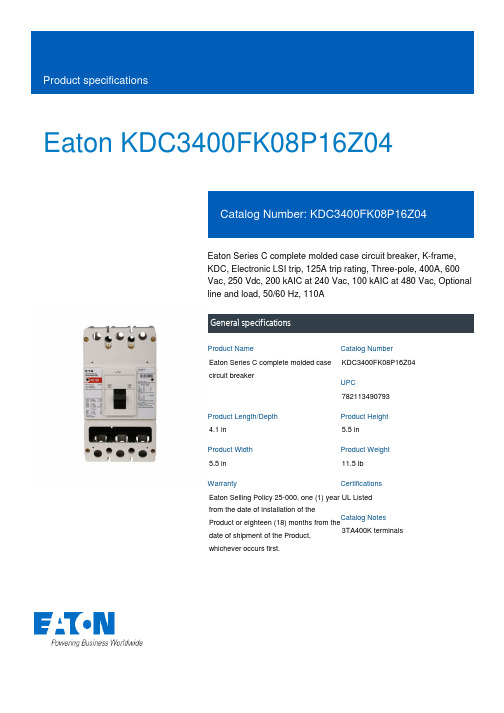
Eaton KDC3400FK08P16Z04Eaton Series C complete molded case circuit breaker, K-frame, KDC, Electronic LSI trip, 125A trip rating, Three-pole, 400A, 600 Vac, 250 Vdc, 200 kAIC at 240 Vac, 100 kAIC at 480 Vac, Optional line and load, 50/60 Hz, 110AGeneral specificationsEaton Series C complete molded case circuit breakerKDC3400FK08P16Z047821134907934.1 in5.5 in5.5 in 11.5 lb Eaton Selling Policy 25-000, one (1) year from the date of installation of theProduct or eighteen (18) months from thedate of shipment of the Product, whichever occurs first.UL Listed 3TA400K terminalsProduct NameCatalog Number UPCProduct Length/Depth Product Height Product Width Product Weight WarrantyCertificationsCatalog Notes200 kAIC at 240 Vac100 kAIC at 480 VacK110A125 A400 AThree-poleSeries CFrame only125, 150, 200, 250A adjustable KDC50 to 60 HzFrame onlyOptional line and load600 Vac, 250 VdcElectronic LSI Application of Multi-Wire Terminals for Molded Case Circuit Breakers Application of Tap Rules to Molded Case Breaker TerminalsUL listed 100%-rated molded case circuit breakersStrandAble terminals product aidCircuit breaker motor operators product aidMulti-wire lugs product aidCurrent limiting Series C molded case circuit breakers product aidPlug-in adapters for molded case circuit breakers product aidMotor protection circuit breakers product aidPower metering and monitoring with Modbus RTU product aidBreaker service centersMolded case circuit breakers catalogEaton's Volume 4—Circuit ProtectionInstruction Leaflet for the KES 310+ Electronic Trip UnitInstallation Instructions for DK, KDB, KD, HKD, KDC, KW, HKW, KWC, CKD, CHKD Circuit Breakers and Molded Case SwitchesCircuit breakers explainedCircuit Breakers ExplainedSeries C J-Frame molded case circuit breakers time current curvesSeries C F-Frame molded case circuit breakersMOEM MCCB product selection guideSeries C G-Frame molded case circuit breakers time current curvesEaton Specification Sheet - KDC3400FK08P16Z04Selling Policy 25-000 - Distribution and Control Products and ServicesImplementation of arc flash mitigating solutions at industrial manufacturing facilitiesInterrupt ratingFrameRated permanent current Trip ratingAmperage Rating Number of polesSeriesTypeRating plugCircuit breaker type Frequency ratingCircuit breaker frame type TerminalsVoltage ratingTrip Type Application notesBrochuresCatalogsInstallation instructions MultimediaSpecifications and datasheetsWarranty guidesWhite papersEaton Corporation plc Eaton House30 Pembroke Road Dublin 4, Ireland © 2023 Eaton. All Rights Reserved. Eaton is a registered trademark.All other trademarks areproperty of their respectiveowners./socialmedia。
Eaton 42U 行内冷却系统 SRCOOL33K 商品说明说明书
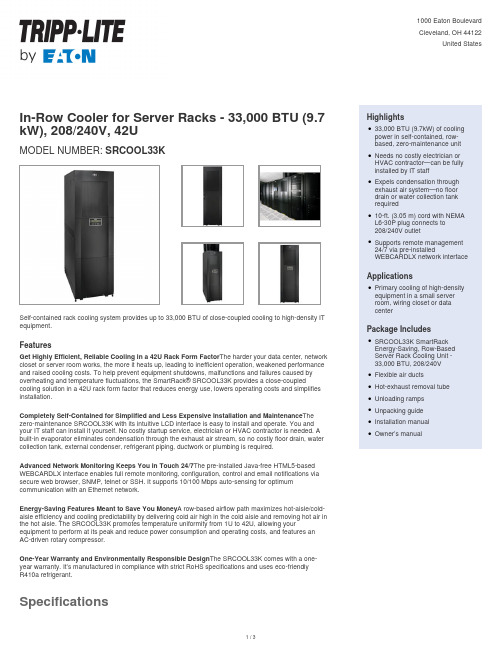
In-Row Cooler for Server Racks - 33,000 BTU (9.7 kW), 208/240V, 42UMODEL NUMBER:SRCOOL33KSelf-contained rack cooling system provides up to 33,000 BTU of close-coupled cooling to high-density IT equipment.FeaturesGet Highly Efficient, Reliable Cooling in a 42U Rack Form Factor The harder your data center, network closet or server room works, the more it heats up, leading to inefficient operation, weakened performance and raised cooling costs. To help prevent equipment shutdowns, malfunctions and failures caused by overheating and temperature fluctuations, the SmartRack® SRCOOL33K provides a close-coupled cooling solution in a 42U rack form factor that reduces energy use, lowers operating costs and simplifies installation.Completely Self-Contained for Simplified and Less Expensive Installation and Maintenance The zero-maintenance SRCOOL33K with its intuitive LCD interface is easy to install and operate. You and your IT staff can install it yourself. No costly startup service, electrician or HVAC contractor is needed. A built-in evaporator eliminates condensation through the exhaust air stream, so no costly floor drain, water collection tank, external condenser, refrigerant piping, ductwork or plumbing is required.Advanced Network Monitoring Keeps You in Touch 24/7The pre-installed Java-free HTML5-based WEBCARDLX interface enables full remote monitoring, configuration, control and email notifications via secure web browser, SNMP, telnet or SSH. It supports 10/100 Mbps auto-sensing for optimum communication with an Ethernet network.Energy-Saving Features Meant to Save You Money A row-based airflow path maximizes hot-aisle/cold-aisle efficiency and cooling predictability by delivering cold air high in the cold aisle and removing hot air in the hot aisle. The SRCOOL33K promotes temperature uniformity from 1U to 42U, allowing your equipment to perform at its peak and reduce power consumption and operating costs, and features anAC-driven rotary compressor.One-Year Warranty and Environmentally Responsible Design The SRCOOL33K comes with a one-year warranty. It’s manufactured in compliance with strict RoHS specifications and uses eco-friendlyR410a refrigerant.Highlights33,000 BTU (9.7kW) of coolingpower in self-contained, row-based, zero-maintenance unit qNeeds no costly electrician orHVAC contractor—can be fullyinstalled by IT staffqExpels condensation throughexhaust air system—no floordrain or water collection tankrequiredq10-ft. (3.05 m) cord with NEMAL6-30P plug connects to208/240V outletqSupports remote management24/7 via pre-installedWEBCARDLX network interface qApplicationsPrimary cooling of high-densityequipment in a small serverroom, wiring closet or datacenterqPackage IncludesSRCOOL33K SmartRackEnergy-Saving, Row-BasedServer Rack Cooling Unit -33,000 BTU, 208/240VqFlexible air ductsqHot-exhaust removal tubeqUnloading rampsqUnpacking guideqInstallation manualqOwner’s manualqSpecifications© 2023 Eaton. All Rights Reserved. Eaton is a registered trademark. All other trademarks are the property of their respective owners.。
美国电力公司Eaton产品说明书-PDG21F0020TFFJ
Eaton PDG21F0020TFFJEaton Power Defense molded case circuit breaker, Globally Rated, Frame 2, Single Pole, 20A, 25kA/480V, T-M (Fxd-Fxd) TU, Standard Line and Load (PDG2X1T100)Eaton Power Defense molded case circuit breakerPDG21F0020TFFJ 78667923563888.9 mm 152.4 mm 35.1 mm 2.041 kg Eaton Selling Policy 25-000, one (1) year from the date of installation of theProduct or eighteen (18) months from thedate of shipment of the Product,whichever occurs first.RoHS Compliant IEC 60947-2UL 489CCC MarkedCSAProduct NameCatalog Number UPCProduct Length/Depth Product Height Product Width Product Weight WarrantyCompliancesCertifications25 kAIC at 480 Vac260020 ASingle-pole600 VPD2 Global25 kAIC Icu/ 20 kAIC Ics/ 52.5 kAIC Icm @440V (IEC)10 kAIC Icu @125 Vdc18 kAIC Icu/ 15/13 kAIC Ics/ 37.8 kAIC Icm @525V South Africa (IEC)35 kAIC Icu/ 35 kAIC Ics/ 73.5 kAIC Icm @240V (IEC)20 kAIC Icu/ 20 kAIC Ics/ 42 kAIC Icm @480V Brazil (IEC)25 kAIC Icu/ 25 kAIC Ics/ 52.5 kAIC Icm @380-415V (IEC)14 kAIC @600V (UL/CSA)35 kAIC @240V (UL)25 kAIC @480V (UL)10 kAIC Icu @250 VdcThermomagneticClass AComplete breakerStandard Line and Load600 VacT-M (Fxd-Fxd) TU Eaton Power Defense MCCB PDG21F0020TFFJ 3D drawingConsulting application guide - molded case circuit breakersPower Defense molded case circuit breaker selection posterPower Defense brochurePower Defense technical selling bookletPower Defense molded case circuit breakers - Frame 2 product aidMolded case circuit breakers catalogPower Defense Declaration concerning California’s Proposition 65PDG2 CB reportPDG4 CB reportPDG4 CCC certificationEU Declaration of Conformity - Power Defense molded case circuit breakersPower Defense Frame 2 tunnel terminal (aluminum), 100A, 1 pole instructions - IL012237EN H01Power Defense Frame 1-2-3-4 IP door barrier assembly instructions - IL012278ENPower Defense Frame 2 box terminal (steel), 100A, 1 pole instructions - IL012234EN H01Power Defense Frame 2 locking devices and handle block instructions - IL012149ENPower Defense Frame 2/3/4/5/6 voltage neutral sensor module wiring instructions – IL012316ENPower Defense Frame 2 PDG2 and PDC(E)9 breaker instructions -IL012106ENPower Defense Frame 2 clamp terminal (steel), 20A, 1 pole instructions- IL012246EN H01Power Defense Frame 2 tunnel terminal (aluminum), 150A, 1 pole instructions- IL012238EN H01Power Defense Frame 2 box terminal (aluminum), 225A, 1 pole instructions - IL012235EN H01Power Defense Frame 2 tunnel terminal kits - PDG2X1TA225KInterrupt ratingFrameRated operation voltage (Ue) at AC - max Amperage RatingNumber of polesVoltage rating - maxCircuit breaker typeInterrupt rating rangeSwitch off techniqueClassCircuit breaker frame typeTerminalsVoltage ratingTrip Type 3D CAD drawing package Application notes BrochuresCatalogsCertification reports Installation instructionsEaton Corporation plc Eaton House30 Pembroke Road Dublin 4, Ireland © 2023 Eaton. All Rights Eaton is a registered trademark.All other trademarks areproperty of their respectiveinstructions- IL012239EN H01Power Defense Frame 2 tunnel terminal (aluminum), 50A, 1 pole instructions - IL012236EN H01Power Defense Frame 2 TMTU Aux, Alarm, ST and UVR Animated Instructions.rhPower Defense Frame 2 withTMTU, Shunt Trip_UVR Animated Instructions.rh Power Defense Frame 3 Variable Depth Rotary Handle Mechanism Installation How-To VideoPower Defense Frame 6 Trip Unit How-To Video Power Defense Frame 5 Trip Unit How-To Video Power Defense molded case circuit breakersPower Defense Frame 2 Variable Depth Rotary Handle Mechanism Installation How-To VideoEaton Power Defense for superior arc flash safety Power Defense Breakers Eaton Specification Sheet - PDG21F0020TFFJ Power Defense time current curve Frame 2 - PD2Molded case and low-voltage power circuit breaker health Making a better machineSingle and double break MCCB performance revisited Intelligent circuit protection yields space savings Molded case and low-voltage breaker health Safer by design: arc energy reduction techniquesInstallation videosMultimediaSpecifications and datasheetsTime/current curvesWhite papersReserved.owners./socialmedia。
2017年6月 Eaton 电子产品说明书
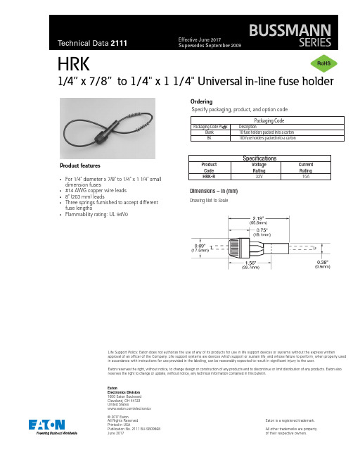
Eaton Electronics Division 1000 Eaton Boulevard Cleveland, OH 44122United States /electronics© 2017 Eaton All Rights Reserved Printed in USA Publication No. 2111 BU-SB09868 June 2017Eaton is a registered trademark.All other trademarks are property of their respective owners.Life Support Policy: Eaton does not authorize the use of any of its products for use in life support devices or systems without the express written approval of an officer of the Company. Life support systems are devices which support or sustain life, and whose failure to perform, when properly used in accordance with instructions for use provided in the labeling, can be reasonably expected to result in significant injury to the user.Eaton reserves the right, without notice, to change design or construction of any products and to discontinue or limit distribution of any products. Eaton also reserves the right to change or update, without notice, any technical information contained in this bulletin.H RK 1/4” x 7/8” to 1/4" x 1 1/4" Universal in-line fuse holderProduct features•For 1/4" diameter x 7/8" to 1/4" x 1 1/4" smalldimension fuses •#14 AWG copper wire leads •8" (203 mm) leads •Three springs furnished to accept different fuse lengths •Flammability rating: UL 94V0 OrderingSpecify packaging, product, and option code SpecificationsProduct Voltage Current Code Rating Rating HRK-R32V 15A Dimensions – in (mm)Drawing Not to Scale。
艾默生精密空调操保手册
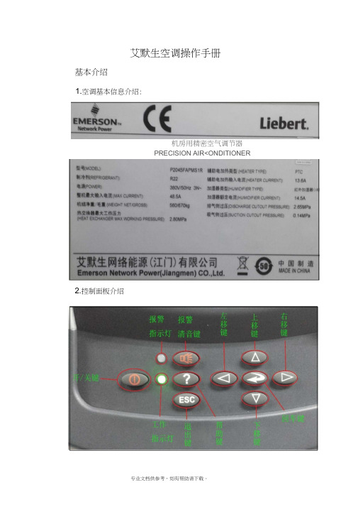
艾默生空调操作手册基本介绍1.空调基本信息介绍:机房用精密空气调节器PRECISION AIR<ONDITIONER 2.控制面板介绍o进LIu菜-甲r (I)1后再1L*按o设设 置 的②③ I 3.控制面板的操作:① 设定点:按回车键进入菜单,再按回车键,通过方向键输入密码。
按下移键选中设定点图标(如下图所示),按 回车键进入菜单 回车,选着索要更改的项目,按回车键,进入到如下图所 示的画面,按上移键或下移键改变要改变的数值, 然后按 回车键确定。
修改完毕后按退出键返回主界面占J可F 1_I■. ■ ""^一・-L|i 吐--IhMMiJ 1,1 ■数值有:⑴温度设定⑵湿度设定⑶湿度控制⑷送风功能⑸送风温度⑹备份温限注:其他菜单设置的操作步骤与设定点设置方法相同设备保养1、更换过滤网①打开机柜门,将机柜顶部两个旧的过滤网取下来②将新的过滤网平稳的放在机柜的顶部(注意方向)2、更换风机皮带①空调关机,在确定停止后,打开机柜门取下挡板检查皮是否有断裂、老化现象③安装皮带(注意:防止皮带与皮带轮之间夹手)④安装挡板。
3、清洗水槽①空调关机拆下两块挡板,拆下立柱上的螺丝②将水位传感器拆下来器拆下来。
④拆掉水槽两端螺丝,平行抽出水槽,清洗用螺丝刀松开卡子螺丝用手拧下排先*管9S⑤清洗完毕按顺序安装。
- 1、下载文档前请自行甄别文档内容的完整性,平台不提供额外的编辑、内容补充、找答案等附加服务。
- 2、"仅部分预览"的文档,不可在线预览部分如存在完整性等问题,可反馈申请退款(可完整预览的文档不适用该条件!)。
- 3、如文档侵犯您的权益,请联系客服反馈,我们会尽快为您处理(人工客服工作时间:9:00-18:30)。
目录
目录 Index
伊顿公司介绍
公司介绍 .......................................................................................................................................................................... 1 伊顿在中国 ...................................................................................................................................................................... 1 伊頓公司节能环保介绍 .................................................................................................................................................... 1
技术参数
技术参数 - 主机 ................................................................................................................................................................11 技术参数 - 冷凝器 .............................................................................................................................................................12
1 伊頓 SAC 精密空调
应用范围
● 计算机房和数据中心 (IDC) ● UPS 和电池室 ● 中、大型交换机房和移动机房 ● 工业控制室 ● 医院和检测室 ● 高精密环境及实验室
产品简介
产品简介
伊顿精密空调简介
数码时代,虚拟化、云计算、高速运算正在重新定义 IT 行业,搜索引擎、社交平台、博客、 即时通讯正在改变人类的生活和重组社会。所有这一切都要基于数据中心,数据中心 成了当今人类社会不可缺少的一部分,渗透到了人类活动的每一个角落。
产品性能特点
大风量设计,业界领先的能效比和显热比 ....................................................................................................................... 3 优异的温湿控制性能与可靠性 ......................................................................................................................................... 4 智能控制和管理 ............................................................................................................................................................... 5 AC 直联风机,风量可调节 .............................................................................................................................................. 5 全正面维护,方便操作 .................................................................................................................................................... 7 紧凑型设计,占地面积小,极大地节约机房空间 ............................................................................................................ 9 丰富齐全的选配件 ........................................................................................................................................................... 9 可与伊顿 UPS 和配电系统无缝集成 ................................................................................................................................ 9
通过技术创新保护并改善环境是伊顿关注的要务之一,伊顿在可持续发展所作出的努力也得到各方 的认可。
身为多元化的动力管理专家,伊顿重视在中国的长期承诺和社会责任,一直以来都将可持续发展战 略身体力行,积极推动绿色产品和技术创新,并与国内产业紧密合作,为本土客户提供更有效的动 力管理方案。
位于美国俄亥俄州克利夫兰市的伊顿总部大楼
伊顿SAC精密空调
伊顿SAC精密空调
专注于机房制冷
可持续发展 为您的业务创造可持续的优势。
伊顿致力于可持续发展,为您的业务创造可持续的优势
我们的业务以价值观念为依托,并承诺“以正确的方式开展业务”。 这不仅仅是一项理念,更包括具体的评价标准,衡量我们在世界各地的业务运营。 我们的各个业务部门全面秉持可持续发展的理念 -- 深入我们生活和工作的方式,以及我们设计产品、管理员工和业务运营的方法。 我们根据一系列标准,仔细评价自身环境、健康与安全表现,并通过年度可持续发展报告公布相关信息。 我们的努力正在取得成效:在过去的几年里,我们大幅度降低了温室气体排放水平,合乎我们对商业圆桌会议气候变化 RESOLVE 计划所做出的承诺,即到 2012 年降低温室气体排放 18%。 我们与客户和其它企业分享最佳实践经验,进一步推广成功经验。伊顿产品能够以许多不同方法帮助客户实现可持续发展目标 从降低建筑物能耗到提高替代能源的成本效益和可靠性水平。
在中国的投资保证了伊顿在这一充满活力的市场得以持续发展。得益于并购和自身业务的增长,公 司已经实现 2010 年在中国市场 10 亿美元的销售目标。
伊顿公司节能环保介绍
中国已成为全球可持续发展进程中新崛起的领导者。 2009 年哥本哈根联合国气候变化大会前夕, 中国政府公布了到 2020 年,中国的单位国内生产总值二氧化碳排放比 2005 年下降 40% -45%的 碳减排目标。清洁技术、可再生资源、能源效率、减排和循环利用等已成为在中国最受关注的头等 大事。
随着计算需求和数据传输迅猛增长的需求,当前的数据中心也面临了巨大的挑战,其中最重要的 挑战是制冷和节能。
伊顿全新推出的机房精密空调配合伊顿的气流管理系统(AMS)能够大大优化数据中心设备,提 高信息处理密度,增强数据中心的节能环保优势。
伊顿 SAC 系列风冷型精密空调针对电子设备的高显热设计,大风量小焓差,自动对机房进行制冷、 加热、加湿、除湿等控制调节来维持机房的恒温恒湿,有效去除计算机因运算而产生的显热。其 高效紧凑的设计,使得在极小的占地面积情况下发挥最大的制冷能力。专业的规划、精准的配置、 丰富的选件能为不同客户提供最合适可靠的机房温度控制方案。
伊顿在ห้องสมุดไป่ตู้国
伊顿公司于 1993 年进入中国市场并设立首家合资企业,此后通过并购、合资和独资的形式迅速发 展在中国的业务。2009 年,公司位于上海市长宁区的新亚太区总部大楼正式落成启动。今天,伊 顿旗下所有业务集团都已在中国制造产品,通过提供创造性的工业技术和高质量的产品,在中国市 场市场扮演积极的角色。目前伊顿在中国已拥有 27 家工厂和 1 万多名员工。伊顿还在中国设立研 发中心,并与多所大学开展了研发合作项目。
所获奖项 亚太区 2010 年度杰出电源质量企业奖 伊顿亚太区总部大楼获“能源与环境设计先锋“金级认证 2010 企业社会责任奖 2010 社会责任优秀企业 世界低碳环境中国推动力 100 强企业 中国 50 绿公司十佳
颁发机构 Frost&Sullivan 2010 年度亚太地区信息与通讯技术颁奖大会 美国绿色建筑委员会 上海美国商会 《中国企业报》& 中国外商投资企业协会 第三届世界环保大会 《商务周刊》
产品简介
伊顿精密空调简介 ........................................................................................................................................................... 2 应用范围 ......................................................................................................................................................................... 2
身为多元化的动力管理专家,伊顿 重视在中国的长期承诺和社会责 任,一直以来都将可持续发展战略 身体力行,积极推动绿色产品和技 术创新,并与国内产业紧密合作, 为本土客户提供更有效的动力管理 方案。