雷达系统的介绍-外文翻译
SA雷达系统概述

SA雷达系统概述雷达(Radar)是一种利用电磁波进行探测和定位的技术,是目前最为主要和广泛应用的远程探测手段之一、它通过发射电磁波并接收返回的信号,利用信号的特征进行目标检测、测距、测速、成像等操作。
雷达系统以其无人操作、全天候、长距离、准确性高等优点在军事、民用、科学研究等各个领域得到了广泛的应用和发展。
雷达系统主要由发射系统、接收系统、处理系统和显示系统四个主要部分组成。
发射系统是雷达系统的核心组件之一,它负责产生和发射出信号。
根据不同需求,雷达可以通过发射不同频率的电磁波来适应不同的应用场景,如短距离的微波雷达、长距离的超过视距雷达等等。
在发射系统中,雷达通常使用发射天线来向特定方向辐射电磁波。
接收系统是指接收来自目标反射回来的信号的部分。
雷达接收系统的主要部件是接收天线,它负责接收到达的电磁波,并将其转化为电信号。
接收系统还包括放大器、滤波器和混频器等元件,用于将接收到的微弱信号放大、滤波和变频,以便进行后续的处理。
处理系统是负责对接收到的信号进行处理和分析的部分。
它通常由数字信号处理器(DSP)和计算机组成。
首先,处理系统会对接收到的信号进行数字化,然后利用各种信号处理算法进行目标检测、特征提取、参数估计等操作,最终得到关于目标的信息。
显示系统是把雷达数据以可视化的方式呈现给人类操作员或其他系统使用的部分。
雷达显示系统通常由显示器组成,可以显示雷达扫描的区域地图、目标的位置和运动轨迹等信息。
此外,雷达显示系统也可以通过声音、光线等方式进行报警和指示。
雷达系统的工作原理主要基于电磁波的回波特性。
当雷达向目标发送电磁波时,目标会对电磁波进行反射、散射、衍射等过程,形成回波信号。
雷达接收到这些回波信号后,通过测量回波信号的强度、相位、多普勒频移等特征,可以实现目标的检测、定位和跟踪。
雷达系统的应用十分广泛。
在军事领域,雷达系统可用于提供空中、海上和地面目标的情报,协助导弹拦截、飞行器导航和目标识别等任务。
雷达系统简介
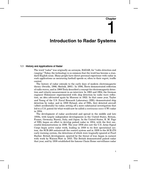
Chapter1Introduction to Radar Systems1.1History and Applications of RadarThe word“radar”was originally an acronym,RADAR,for“ra dio d etection a ndr anging.”Today,the technology is so common that the word has become a stan-dard English noun.Many people have direct personal experience with radar insuch applications as measuring fastball speeds or,often to their regret,trafficcontrol.The history of radar extends to the early days of modern electromagnetictheory(Swords,1986;Skolnik,2001).In1886,Hertz demonstrated reflectionof radio waves,and in1900Tesla described a concept for electromagnetic detec-tion and velocity measurement in an interview.In1903and1904,the Germanengineer H¨ulsmeyer experimented with ship detection by radio wave reflec-tion,an idea advocated again by Marconi in1922.In that same year,Taylorand Young of the U.S.Naval Research Laboratory(NRL)demonstrated shipdetection by radar,and in1930Hyland,also of NRL,first detected aircraft(albeit accidentally)by radar,setting off a more substantial investigation thatled to a U.S.patent for what would now be called a continuous wave(CW)radarin1934.The development of radar accelerated and spread in the middle and late1930s,with largely independent developments in the United States,Britain,France,Germany,Russia,Italy,and Japan.In the United States,R.M.Pageof NRL began an effort to develop pulsed radar in1934,with thefirst suc-cessful demonstrations in1936.The year1936also saw the U.S.Army SignalCorps begin active radar work,leading in1938to itsfirst operational sys-tem,the SCR-268antiaircraftfire control system and in1939to the SCR-270early warning system,the detections of which were tragically ignored at PearlHarbor.British development,spurred by the threat of war,began in earnestwith work by Watson-Watt in1935.The British demonstrated pulsed radarthat year,and by1938established the famous Chain Home surveillance radar12Chapter Onenetwork that remained active until the end of World War II.They also builtthefirst airborne interceptor radar in1939.In1940,the United States andBritain began to exchange information on radar development.Up to this time,most radar work was conducted at high frequency(HF)and very high frequency(VHF)wavelengths;but with the British disclosure of the critical cavity mag-netron microwave power tube and the United States formation of the RadiationLaboratory at the Massachusetts Institute of Technology,the groundwork waslaid for the successful development of radar at the microwave frequencies thathave predominated ever since.Each of the other countries mentioned also carried out CW radar experiments,and eachfielded operational radars at some time during the course of WorldWar II.Efforts in France and Russia were interrupted by German occupation.On the other hand,Japanese efforts were aided by the capture of U.S.radarsin the Philippines and by the disclosure of German technology.The Germansthemselves deployed a variety of ground-based,shipboard,and airborne sys-tems.By the end of the war,the value of radar and the advantages of microwavefrequencies and pulsed waveforms were widely recognized.Early radar development was driven by military necessity,and the military isstill the dominant user and developer of radar itary applicationsinclude surveillance,navigation,and weapons guidance for ground,sea,andair itary radars span the range from huge ballistic missile defensesystems tofist-sized tactical missile seekers.Radar now enjoys an increasing range of applications.One of the most com-mon is the police traffic radar used for enforcing speed limits(and measuringthe speed of baseballs and tennis serves).Another is the“color weather radar”familiar to every viewer of local television news.The latter is one type of mete-orological radar;more sophisticated systems are used for large-scale weathermonitoring and prediction and atmospheric research.Another radar applica-tion that affects many people is found in the air traffic control systems usedto guide commercial aircraft both en route and in the vicinity of airports.Avi-ation also uses radar for determining altitude and avoiding severe weather,and may soon use it for imaging runway approaches in poor weather.Radar iscommonly used for collision avoidance and buoy detection by ships,and is nowbeginning to serve the same role for the automobile and trucking industries.Finally,spaceborne(both satellite and space shuttle)and airborne radar is animportant tool in mapping earth topology and environmental characteristicssuch as water and ice conditions,forestry conditions,land usage,and pollution.While this sketch of radar applications is far from exhaustive,it does indicatethe breadth of applications of this remarkable technology.This text tries to present a thorough,straightforward,and consistent descrip-tion of the signal processing aspects of radar technology,focusing primarily onthe more fundamental functions common to most radar systems.Pulsed radarsare emphasized over CW radars,though many of the ideas are applicable toboth.Similarly,monostatic radars,where the transmitter and receiver anten-nas are collocated(and in fact are usually the same antenna),are emphasizedIntroduction to Radar Systems3 over bistatic radars,where they are significantly separated,though again manyof the results apply to both.The reason for this focus is that the majority of radarsystems are monostatic,pulsed designs.Finally,the subject is approached froma digital signal processing(DSP)viewpoint as much as practicable,both be-cause most new radar designs rely heavily on digital processing and becausethis approach can unify concepts and results often treated separately.1.2Basic Radar FunctionsMost uses of radar can be classified as detection,tracking,or imaging.In thistext,the emphasis is on detection and imaging,as well as the techniques ofsignal acquisition and interference reduction necessary to perform these tasks.The most fundamental problem in radar is detection of an object or physicalphenomenon.This requires determining whether the receiver output at a giventime represents the echo from a reflecting object or only noise.Detection deci-sions are usually made by comparing the amplitude A(t)of the receiver output(where t represents time)to a threshold T(t),which may be set a priori in theradar design or may be computed adaptively from the radar data;in Chap.6itwill be seen why this detection technique is appropriate.The time required fora pulse to propagate a distance R and return,thus traveling a total distance2R,is just2R/c;thus,if y(t)>T(t)at some time delay t0after a pulse istransmitted,it is assumed that a target is present at rangeR=ct02(1.1)where c is the speed of light.†Once an object has been detected,it may be desirable to track its location or velocity.A monostatic radar naturally measures position in a spherical coordi-nate system with its origin at the radar antenna’s phase center,as shown in Fig.1.1.In this coordinate system,the antenna look direction,sometimes called the boresight direction,is along the+x axis.The angleθis called azimuth angle, whileφis called elevation angle.Range R to the object follows directly from the elapsed time from transmission to detection as just described.Elevation and azimuth angleφandθare determined from the antenna orientation,since the target must normally be in the antenna main beam to be detected.Velocity is estimated by measuring the Doppler shift of the target echoes.Doppler shift provides only the radial velocity component,but a series of measurements of position and radial velocity can be used to infer target dynamics in all three dimensions.Because most people are familiar with the idea of following the movement of a“blip”on the radar screen,detection and tracking are the functions most com-monly associated with radar.Increasingly,however,radars are being used to†c=2.99792458×10⁸m/s in a vacuum.A value of c=3×10⁸m/s is normally used except where very high accuracy is required.4Chapter OneFigure1.1Spherical coordinate system for radar measurements.generate two-dimensional images of an area.Such images can be analyzed forintelligence and surveillance purposes,for elevation/topology mapping,or foranalysis of earth resources issues such as mapping,land use,ice cover analysis,deforestation monitoring,and so forth.They can also be used for“terrain fol-lowing”navigation by correlating measured imagery with stored maps.Whileradar images have not achieved the resolution of optical images,the very lowattenuation of electromagnetic waves at microwave frequencies gives radar theimportant advantage of“seeing”through clouds,fog,and precipitation verywell.Consequently,imaging radars generate useful imagery when optical in-struments cannot be used at all.The quality of a radar system is quantified with a variety offigures of merit,depending on the function being considered.In analyzing detection perfor-mance,the fundamental parameters are the probability of detection P D andthe probability of false alarm P FA.If other system parameters arefixed,in-creasing P D always requires accepting a higher P FA as well.The achievablecombinations are determined by the signal and interference statistics,espe-cially the signal-to-interference ratio(SIR).When multiple targets are presentin the radarfield of view,additional considerations of resolution and side lobesarise in evaluating detection performance.For example,if two targets cannotbe resolved by a radar,they will be registered as a single object.If side lobesare high,the echo from one strongly reflecting target may mask the echo from anearby but weaker target,so that again only one target is registered when twoare present.Resolution and side lobes in range are determined by the radarwaveform,while those in angle are determined by the antenna pattern.In radar tracking,the basicfigure of merit is accuracy of range,angle,andvelocity estimation.While resolution presents a crude limit on accuracy,withappropriate signal processing the achievable accuracy is ultimately limited ineach case by the SIR.Introduction to Radar Systems5 In imaging,the principalfigures of merit are spatial resolution and dynamic range.Spatial resolution determines what size objects can be identified in the final image,and therefore to what uses the image can be put.For example,a radar map with1km by1km resolution would be useful for land use studies, but useless for military surveillance of airfields or missile sites.Dynamic range determines image contrast,which also contributes to the amount of information that can be extracted from an image.The purpose of signal processing in radar is to improve thesefigures of merit. SIR can be improved by pulse integration.Resolution and SIR can be jointly improved by pulse compression and other waveform design techniques,such as frequency agility.Accuracy benefits from increased SIR and“filter splitting”interpolation methods.Side lobe behavior can be improved with the same win-dowing techniques used in virtually every application of signal processing.Each of these topics are discussed in the chapters that follow.Radar signal processing draws on many of the same techniques and con-cepts used in other signal processing areas,from such closely relatedfields as communications and sonar to very different applications such as speech and image processing.Linearfiltering and statistical detection theory are central to radar’s most fundamental task of target detection.Fourier transforms,im-plemented using fast Fourier transform(FFT)techniques,are ubiquitous,being used for everything from fast convolution implementations of matchedfilters, to Doppler spectrum estimation,to radar imaging.Modern model-based spec-tral estimation and adaptivefiltering techniques are used for beamforming and jammer cancellation.Pattern recognition techniques are used for target/clutter discrimination and target identification.At the same time,radar signal processing has several unique qualities that differentiate it from most other signal processingfields.Many modern radars are coherent,meaning that the received signal,once demodulated to baseband, is complex-valued rather than real-valued.Radar signals have very high dy-namic ranges of several tens of decibels,in some extreme cases approaching 100dB.Thus,gain control schemes are common,and side lobe control is often critical to avoid having weak signals masked by stronger ones.SIR ratios are often relatively low.For example,the SIR at the point of detection may be only 10to20dB,while the SIR for a single received pulse prior to signal processing is frequently less than0dB.Especially important is the fact that,compared to most other DSP appli-cations,radar signal bandwidths are large.Instantaneous bandwidths for an individual pulse are frequently on the order of a few megahertz,and in some high-resolution radars may reach several hundred megahertz and even as high as1GHz.This fact has several implications for digital signal processing.For example,very fast analog-to-digital(A/D)converters are required.The diffi-culty of designing good converters at megahertz sample rates has historically slowed the introduction of digital techniques into radar signal processing.Even now,when digital techniques are common in new designs,radar word lengths in high-bandwidth systems are usually a relatively short8to12bits,rather6Chapter OneFigure1.2Block diagram of a pulsed monostatic radar.than the16bits common in many other areas.The high data rates have alsohistorically meant that it has often been necessary to design custom hardwarefor the digital processor in order to obtain adequate throughput,that is,to“keep up with”the onslaught of data.This same problem of providing adequatethroughput has resulted in radar signal processing algorithms being relativelysimple compared to,say,sonar processing techniques.Only in the late1990s hasMoore’s Law†provided us enough computing power to host radar algorithms fora wide range of systems on commercial hardware.Equally important,this sametechnological progress has allowed the application of new,more complex algo-rithms to radar signals,enabling major improvements in detection,tracking,and imaging capability.1.3Elements of a Pulsed RadarFigure1.2is one possible block diagram of a simple pulsed monostatic radar.The waveform generator output is the desired pulse waveform.The transmittermodulates this waveform to the desired radio frequency(RF)and amplifies it toa useful power level.The transmitter output is routed to the antenna througha duplexer,also called a circulator or T/R switch(for transmit/receive).Thereturning echoes are routed,again by the duplexer,into the radar receiver.The receiver is usually a superheterodyne design,and often thefirst stage is Gordon Moore’s famous1965prediction was that the number of transistors on an integrated circuit would double every18to24months.This prediction has held remarkably true for nearly40years,enabling the computing and networking revolutions that began in the1980s.Introduction to Radar Systems7a low-noise RF amplifier.This is followed by one or more stages of modulationof the received signal to successively lower intermediate frequencies(IFs)andultimately to baseband,where the signal is not modulated onto any carrierfrequency.Each modulation is carried out with a mixer and a local oscillator(LO).The baseband signal is next sent to the signal processor,which performssome or all of a variety of functions such as pulse compression,matchedfilter-ing,Dopplerfiltering,integration,and motion compensation.The output of thesignal processor takes various forms,depending on the radar purpose.A track-ing radar would output a stream of detections with measured range and anglecoordinates,while an imaging radar would output a two-or three-dimensionalimage.The processor output is sent to the system display,the data processor,or both as appropriate.The configuration of Fig.1.2is not unique.For example,many systems per-form some of the signal processing functions at IF rather than baseband;matchedfiltering,pulse compression,and some forms of Dopplerfiltering arevery common examples.The list of signal processing functions is redundant aswell.For example,pulse compression and Dopplerfiltering can both be consid-ered part of the matchedfiltering process.Another characteristic which differsamong radars is at what point in the system the analog signal is digitized.Oldersystems are,of course,all analog,and many currently operational systems donot digitize the signal until it is converted to baseband.Thus,any signal pro-cessing performed at IF must be done with analog techniques.Increasingly,new designs digitize the signal at an IF stage,thus moving the A/D convertercloser to the radar front end and enabling digital processing at IF.Finally,thedistinction between signal processing and data processing is sometimes unclearor artificial.In the next few subsections,the major characteristics of these principal radarsubsystems are briefly discussed.1.3.1Transmitter and waveform generatorThe transmitter and waveform generator play a major role in determining thesensitivity and range resolution of radar.Radar systems have been operatedat frequencies as low as2MHz and as high as220GHz(Skolnik,2001);laserradars operate at frequencies on the order of1012to1015Hz,corresponding towavelengths on the order of0.3to30µm(Jelalian,1992).However,most radarsoperate in the microwave frequency region of about200MHz to about95GHz,with corresponding wavelengths of0.67m to3.16mm.Table1.1summarizes theletter nomenclature used for the common nominal radar bands(IEEE,1976).The millimeter wave band is sometimes further decomposed into approximatesub-bands of36to46GHz(Q band),46to56GHz(V band),and56to100GHz(W band)(Eaves and Reedy,1987).Within the HF to K a bands,specific frequencies are allocated by interna-tional agreement to radar operation.In addition,at frequencies above X band,atmospheric attenuation of electromagnetic waves becomes significant.8Chapter OneTABLE1.1Letter Nomenclature for Nominal RadarFrequency BandsBand Frequencies WavelengthsHF3–30MHz100–10mVHF30–300MHz10–1mUHF300MHz–1GHz1–30cmL1–2GHz30–15cmS2–4GHz15–7.5cmC4–8GHz7.5–3.75cmX8–12GHz 3.75–2.5cmK u12–18GHz 2.5–1.67cmK18–27GHz 1.67–1.11cmK a27–40GHz 1.11cm–7.5mmmm40–300GHz7.5–1mmConsequently,radar in these bands usually operates at an“atmosphericwindow”frequency where attenuation is relatively low.Figure1.3illustratesthe atmospheric attenuation for one-way propagation over the most commonradar frequency ranges under one set of atmospheric conditions.Most K a bandradars operate near35GHz and most W band systems operate near95GHzbecause of the relatively low atmospheric attenuation at these wavelengths.Lower radar frequencies tend to be preferred for longer range surveillanceapplications because of the low atmospheric attenuation and high availablepowers.Higher frequencies tend to be preferred for higher resolution,shorterrange applications due to the smaller achievable antenna beamwidths for agiven antenna size,higher attenuation,and lower available powers.Figure1.3One-way atmospheric attenuation of electromagnetic waves.(Source:EWand Radar Systems Engineering Handbook,Naval Air Warfare Center,Weapons Di-vision,/)Introduction to Radar Systems9Figure1.4Effect of different rates of precipitation on one-way atmospheric atten-uation of electromagnetic waves.(Source:EW and Radar Systems EngineeringHandbook,Naval Air Warfare Center,Weapons Division,http://ewhdbks.mugu./)Weather conditions can also have a significant effect on radar signal propa-gation.Figure1.4illustrates the additional one-way loss as a function of RF frequency for rain rates ranging from a drizzle to a tropical downpour.X-band frequencies(typically10GHz)and below are affected significantly only by very severe rainfall,while millimeter wave frequencies suffer severe losses for even light-to-medium rain rates.Radar transmitters operate at peak powers ranging from milliwatts to in excess of10MW.One of the more powerful existing transmitters is found in the AN/FPS-108COBRA DANE radar,which has a peak power of15.4MW (Brookner,1988).The interval between pulses is called the pulse repetition in-terval(PRI),and its inverse is the pulse repetition frequency(PRF).PRF varies widely but is typically between several hundred pulses per second(pps)and several tens of thousands of pulses per second.The duty cycle of pulsed sys-tems is usually relatively low and often well below1percent,so that average powers rarely exceed10to20kW.COBRA DANE again offers an extreme exam-ple with its average power of0.92MW.Pulse lengths are most often between about100ns and100µs,though some systems use pulses as short as a few nanoseconds while others have extremely long pulses,on the order of1ms.It will be seen(Chap.6)that the detection performance achievable by a radar improves with the amount of energy in the transmitted waveform.To maximize detection range,most radar systems try to maximize the transmitted power. One way to do this is to always operate the transmitter at full power during a pulse.Thus,radars generally do not use amplitude modulation of the transmit-ted pulse.On the other hand,the nominal range resolution R is determined by the waveform bandwidthβaccording toR=c(1.2)2β10Chapter One(Chap.4).For an unmodulated pulse,the bandwidth is inversely proportional toits duration.To increase waveform bandwidth for a given pulse length withoutsacrificing energy,many radars routinely use phase or frequency modulationof the pulse.Desirable values of range resolution vary from a few kilometers in long-rangesurveillance systems,which tend to operate at lower RFs,to a meter or less invery high-resolution imaging systems,which tend to operate at high RFs.Cor-responding waveform bandwidths are on the order of100kHz to1GHz,andare typically1percent or less of the RF.Few radars achieve10percent band-width.Thus,most radar waveforms can be considered narrowband,bandpassfunctions.1.3.2AntennasThe antenna plays a major role in determining the sensitivity and angular res-olution of the radar.A wide variety of antenna types are used in radar systems.Some of the more common types are parabolic reflector antennas,scanning feedantennas,lens antennas,and phased array antennas.From a signal processing perspective,the most important properties of anantenna are its gain,beamwidth,and side lobe levels.Each of these follows fromconsideration of the antenna power pattern.The power pattern P(θ,φ)describesthe radiation intensity during transmission in the direction(θ,φ)relative tothe antenna boresight.Aside from scale factors,which are unimportant fornormalized patterns,it is related to the radiated electricfield intensity E(θ,φ),known as the antenna voltage pattern,according toP(θ,φ)=|E(θ,φ)|2(1.3) For a rectangular aperture with an illumination function that is separable inthe two aperture dimensions,P(θ,φ)can be factored as the product of separateone-dimensional patterns(Stutzman and Thiele,1998):P(θ,φ)=Pθ(θ)Pφ(φ)(1.4) For most radar scenarios,only the far-field(also called Fraunhofer)powerpattern is of interest.The far-field is conventionally defined to begin at a rangeof D2/λor2D2/λfor an antenna of aperture size D.Consider the azimuth(θ)pattern of the one-dimensional linear aperture geometry shown in Fig.1.5.From a signal processing viewpoint,an important property of aperture anten-nas(such asflat plate arrays and parabolic reflectors)is that the electricfieldintensity as a function of azimuth E(θ)in the farfield is just the inverse Fouriertransform of the distribution A(y)of current across the aperture in the azimuthplane(Bracewell,1999;Skolnik,2001):E(θ)= Dy/2−D y/2A(y)ej2πyλsinθdy(1.5)λ+D y λ−D y )Figure 1.5Geometry for one-dimensional electric field calculation on a rectangularaperture.where the “frequency ”variable is (2π/λ)sin θand is in radians per meter.The idea of spatial frequency will be expanded in Sec.1.4.2.To be more explicit about this point,de fine s =sin θand ζ=y /λ.Substituting these de finitions in Eq.(1.5)givesD y /2λ−D y /2λA (λζ)e j 2πζs d ζ=ˆE (s )(1.6)which is clearly of the form of an inverse Fourier transform.(Thefinite integrallimits are due to the finite support of the aperture.)Note that ˆE(s )=E (sin −1θ),that is,ˆE (s )and E (θ)are related by a nonlinear mapping of the θor s axis.Itof course follows that A (λζ)= +∞−∞ˆE (s )e j 2πζs d s (1.7)The in finite limits in Eq.(1.7)are misleading,since the variableof integrations =sin θcan only range from −1to +1.Because of this,ˆE (s )is zero outside ofthis range on s .Equation (1.5)is a somewhat simpli fied expression,which neglects a range-dependent overall phase factor and a slight amplitude dependence on range (Balanis,1982).This Fourier transform property of antenna patterns will,in Chap.2,allow the use of linear system concepts to understand the effects of the antenna on cross-range resolution and the pulse repetition frequencies needed to avoid spatial aliasing.An important special case of Eq.(1.5)occurs when the aperture current illu-mination is a constant,A (z )=A 0.The normalized far field voltage pattern is then the familiar sinc function,E (θ)=sin[π(D y /λ)sin θ]y (1.8)If the aperture current illumination is separable,then the far field is the product of two Fourier transforms,one in azimuth (θ)and one in elevation (φ).The magnitude of E (θ)is illustrated in Fig.1.6,along with the de finitions for two important figures of merit of an antenna pattern.The angular resolution of the antenna is determined by the width of its main lobe,and is convention-ally expressed in terms of the 3-dB beamwidth .This can be found by setting E (θ)=1/√and solving for the argument α=π(D y /λ)sin θ.The answer can be found numerically to be α=1.4,which gives the value of θat the −3-dB point as θ0=0.445λ/D y .The 3-dB beamwidth extends from −θ0to +θ0and is therefore 3-dB beamwidth ≡θ3=2sin −11.4λy ≈0.89λD yradians (1.9)Thus,the 3-dB beamwidth is 0.89divided by the aperture size in wavelengths.Note that a smaller beamwidth requires a larger aperture or a shorter wave-length.Typical beamwidths range from as little as a few tenths of a degree to several degrees for a pencil beam antenna where the beam is made as nar-row as possible in both azimuth and elevation.Some antennas are deliberately designed to have broad vertical beamwidths of several tens of degrees for con-venience in wide area search;these designs are called fan beam antennas .The peak side lobe of the pattern affects how echoes from one scatterer affect the detection of neighboring scatterers.For the uniform illumination pattern,the peak side lobe is 13.2dB below the main lobe peak.This is often considered too high in radar systems.Antenna side lobes can be reduced by use of a nonuni-form aperture distribution (Skolnik,2001),sometimes referred to as taperingof Figure 1.6One-way radiation pattern of a uniformly illuminated aperture.The 3-dB beamwidth and peak side lobe de finitions are illustrated.。
radar 术语

radar 术语全文共四篇示例,供读者参考第一篇示例:雷达是目前在军事和民用领域广泛使用的一种探测和跟踪目标的技术。
它通过向目标发射电磁波并接收目标反射的波来确定目标的位置、速度和其他相关信息。
雷达术语是在雷达领域常用的术语,了解这些术语对于理解雷达技术和运作原理至关重要。
1. 雷达系统:雷达系统是由雷达发射器、接收器、天线和信号处理器等组件组成的系统。
它们一起工作来探测和跟踪目标,并将信息传递给操作员或自动控制系统。
2. 发射器:雷达系统中的发射器用于发射电磁波信号。
这些信号通过天线发送到目标,并在目标上产生反射。
3. 接收器:雷达系统中的接收器用于接收从目标反射回来的电磁波信号。
接收器将这些信号转换成可供处理的数据。
4. 天线:雷达系统中的天线用于发射和接收电磁波信号。
天线的设计对雷达系统的性能有着重要影响。
6. 工作模式:雷达系统可以处于不同的工作模式,包括搜索模式和跟踪模式。
搜索模式用于在广阔范围内搜索目标,而跟踪模式用于精确跟踪已发现的目标。
7. 极坐标:雷达系统中常用的坐标系,用于描述目标的位置和距离。
极坐标通常由方位角和仰角组成。
8. 方位角:雷达系统中用于描述目标在水平方向上的位置的角度。
方位角通常从雷达系统正前方开始计算。
10. 系统灵敏度:雷达系统的灵敏度指的是系统能够检测到的最小信号强度。
灵敏度越高,系统可以探测到更小的目标。
11. 脉冲宽度:雷达系统发射的脉冲信号的宽度。
脉冲宽度影响雷达系统对目标的分辨能力。
13. 探测范围:雷达系统可以检测到目标的最大距离。
探测范围受到雷达系统功率、天线性能和目标反射特性的影响。
15. 杂波抑制:雷达系统通过对接收信号进行处理来抑制杂波的干扰。
杂波抑制能力影响雷达系统的性能和准确性。
16. 脉冲压缩:雷达系统通过脉冲压缩技术可以提高雷达系统的分辨率和目标跟踪能力。
17. 后向散射截面:后向散射截面是描述目标对雷达系统反射效果的物理量,它影响雷达系统对目标的探测和跟踪能力。
雷达系统导论概述

ICASSP – International Conference on Acoustics, Speech, and Signal Processing IEEE SP Society主办,年会,3000页左右 ICSP – International Conference on Signal Processing 中国电子学会主办,每两年一届(偶数年),2000页左右 NAECON – National Aerospace and Electronics Conference IEEE AES Society主办,每年一届 International Conference on HF Radio Systems & Techniques IET主办,每三年一届 International Conference on Antennas and Propagation IET主办,每两年一届 IEEE Antennas and Propagation International Symposium IEEE AP Society主办,年会 IGARSS – International Geoscience and Remote Sensing Symposium IEEE GRS Society主办,年会 SPIE Conference, Symposium on ….. SPIE召开的系列研讨会,目前已累积出版数千册 OCEANS – / IEEE OE Society,每年在美国与MTS (the Marine Technology Society) 合办一次会议,在亚太地区(奇数年)、欧洲(偶数年)单独举办一次。
国内期刊
电子学报、Chinese Journal of Electronics 中国电子学会 电子与信息学报、Journal of Electronics (China) 中科院电子所 通信学报 中国通信学会 宇航学报 中国宇航学会 航空学报 中国航空学会 微波学报 中国微波学会 系统工程与电子技术、Journal of System Engineering and Electronics 信号处理、电波科学学报、现代雷达、雷达与对抗、雷达科学与技术、 中国雷达、电子对抗、电子对抗技术、航天电子对抗、舰船电子对抗
什么是雷达

什么是雷达雷达(Radar)是一种利用电磁波进行探测和测量的技术。
它是由英文Radio Detection and Ranging(无线电探测和测距)缩写而来。
雷达系统能够发送出一束电磁波,并接收其反射回来的信号,通过分析这些信号的特征来确定目标物体的位置、速度、方向和其他属性。
雷达技术的发展历史可以追溯到20世纪初。
最初,雷达主要用于军事领域,用于探测和追踪敌方飞机和舰船。
随着科技的进步,雷达技术逐渐应用于民用领域,如天气预报、航空导航和交通控制等。
雷达系统由发射器、接收器和信号处理器组成。
当雷达发射器发出一束电磁波时,它会遇到目标物体并被反射回来。
接收器接收这些反射的信号,并将其传送给信号处理器进行分析。
雷达系统的探测原理基于“回波时间差”原理。
当雷达发射信号时,它记录下发射和接收之间的时间间隔。
通过测量这个时间间隔,可以确定目标物体与雷达系统之间的距离。
通过连续发射信号并记录回波时间差,雷达系统可以得到目标物体的运动信息,如速度和方向。
雷达系统还可以通过分析回波信号的特征来获得目标物体的其他属性。
例如,通过比较接收到的信号的强度和频率变化,雷达系统可以确定目标物体的大小、形状和材质。
这些信息对于区分不同类型的目标物体至关重要。
雷达技术的应用非常广泛。
在军事领域,雷达系统被用于飞机、舰船和导弹的导航和目标追踪。
在天气预报中,雷达系统用于探测降雨和研究气象现象。
在航空导航中,雷达系统用于引导飞机降落和防止碰撞。
此外,雷达技术还被用于交通控制、无人驾驶汽车和安防领域等。
与传统的光学传感器相比,雷达具有许多优势。
首先,雷达系统可以在复杂的天气条件下工作,如雨雪、雾和浓雾。
其次,雷达可以远距离探测目标物体,无需直接视线。
此外,雷达系统对目标物体的大小和形状并不敏感,因此可以在不同环境下进行可靠的探测。
然而,雷达技术也存在一些局限性。
由于雷达使用的是电磁波,因此在某些情况下可能会被其他电子设备干扰。
此外,雷达对目标物体的分辨率有限,无法对小尺寸的物体提供详细信息。
雷达的资料 (2)
雷达的资料1. 介绍雷达(Radar)是由Radio(射频)和Detection(侦测)两个词组成的缩写词,是一种利用电磁波进行远距离目标探测和测量的技术。
雷达技术广泛应用于航空、军事、气象、导航、地质勘探等领域。
本文将详细介绍雷达的原理、分类以及应用。
2. 原理雷达的工作原理基于电磁波的特性以及目标的反射。
雷达系统发射高频电磁波,这些波通过空间传播,并当波束遇到目标时,部分电磁波会被目标表面反射回来。
雷达接收器接收反射回来的波,并根据接收到的信号计算目标的位置、速度、距离等参数。
3. 分类根据使用的频率范围、工作方式和应用领域的不同,雷达可以分为不同的类型:- 基于频率范围的分类: - X波段雷达 - C波段雷达 - S波段雷达 - L波段雷达 - Ku波段雷达 - Ka波段雷达 - 基于工作方式的分类: - 连续波雷达(CW雷达) - 脉冲雷达 - 多普勒雷达 - 合成孔径雷达(SAR) - 基于应用领域的分类: - 军用雷达 - 气象雷达 - 航空雷达 - 地质勘探雷达 - 海洋雷达4. 应用雷达技术在各个领域中都有重要的应用。
以下是一些常见的雷达应用: ### 4.1 军事应用雷达在军事中起到了非常重要的作用。
它可以用于远距离探测敌方目标,提供战场情报,指引导弹和飞机等武器系统。
此外,雷达还可以用于侦测隐形飞机、导弹和潜艇等敌方威胁。
4.2 气象应用气象雷达用于测量降水、云团和其他气象现象,帮助气象学家预测天气变化。
通过测量反射回来的电磁波强度和频率变化,气象雷达可以提供降水的类型、强度和分布等信息。
4.3 航空应用航空雷达用于飞行安全和导航。
它可以检测飞行器和其他飞行物体,帮助飞行员避开障碍物,提供飞行路径规划和导航。
航空雷达在机场和航空监控系统中广泛使用。
4.4 地质勘探应用地质雷达可用于勘探地下的水、矿产、地层、沉积物和其他地质特征。
它可以通过检测不同类型物质的电磁波反射信号来提供地下结构和特征的图像。
01第一章雷达基本工作原理
雷达技术的发展
1886-1888赫兹 赫兹(Germany): 实现了电磁波振荡、发射、接收。 实现了电磁波振荡、发射、接收。 赫兹 1897 波波夫 波波夫(Russian):提出了回声探测器-雷达的初始模型。 提出了回声探测器- 提出了回声探测器 雷达的初始模型。 1936沃森 瓦特 (England):制造对空警戒雷达 第一部实用军事 沃森─瓦特 制造对空警戒雷达-第一部实用军事 沃森 制造对空警戒雷达 雷达 1936 德国“海军上将施佩尔伯爵”号战列舰装备舰载雷达 第一 德国“海军上将施佩尔伯爵”号战列舰装备舰载雷达-第一 部实用的舰载雷达 1938美国海军“New York” 巡洋舰 美国海军“ 巡洋舰XAF型雷达 第一部舰载对空 型雷达-第一部舰载对空 美国海军 型雷达 警戒雷达 1937英国科学家爱德华 鲍恩“安桑”式飞机 第一部机载雷达 英国科学家爱德华·鲍恩 英国科学家爱德华 鲍恩“安桑”式飞机-第一部机载雷达 After WWII 成为了发展快速的导航仪器。 成为了发展快速的导航仪器。 中国:从发达国家引进技术 从发达国家引进技术。 中国 从发达国家引进技术。 现代雷达/ARPA: 具有计算机 构成组合导航 integrated 具有计算机, 现代雷达 navigation system(Loran, GPS, ECDIS), 及自动船桥系统 Automatic bridge navigation system.
距离,方位,速度,航向, 距离,方位,速度,航向,……
导航
(1) 避碰 (2) 定位
第一章 雷达基本工作原理
第一节 雷达测距与测方位原理
岛屿 本船 = Δt=123.5 μs 0 方向扫描 90° ° 本船 245° ° 岛屿 海图平面 目标船 90 方位标志 245 雷达不能“ 感知”目标的背面, 雷达不能 “ 感知 ” 目标的背面 , 因此目标的后沿是不可见的. 因此目标的后沿是不可见的 量程: 量程 12 nm EBL 180 雷达平面 固定距标圈 荧光屏边缘 HL 回波 (at 10 nm) 270 扫描线 目标
雷达术语中英文对照
雷达术语中英文对照1. A型显示器(距离显示器) A scope(range indicator)2. 交流二极管充电A.C. diode charging3. 交流阻抗A.C. impedance4. 交流谐振充电A.C. resonant charging5. A/R型显示器A/R scope6. 电枢控制Aarmature control7. 绝对误差Absolute error8. 吸收性复盖层Absorbent overlay(coverage)9. 减震器Absorber10. 吸收式衰减器Absorptive attenuator11. 交流控制系统AC control system12. 加速度信息Acceleration inFORMation13. 附件Accessory14. 捕捉目标试验Acquisition object test15. 截获概率试验Acquisition probability test16. 低仰角截获试验Acquisition test at the lowest elevation17. 有源滤波器Active filter18. 有源校正网络Active corrective network19. 有源干扰Active jamming20. 阵列单元的有效阻抗Active-impedance of an array element21. 执行元件Actuator(driving) element22. 自适应天线Adaptive antenna23. 自适应天线系统Adaptive antenna system24. 自适应能力Adaptive capability25. 自适应检测器Adaptive detector26. 自适应跳频Adaptive frequency hopping27. 自适应干扰机Adaptive jammer28. 自适应动目标显示Adaptive MTI29. 加法器Adder30. 导纳Admittance31. 气悬体干扰Aerosol jamming32. 通风车Air blower carriage33. 空气滤渍器Air filter34. 空中交通管制雷达Air traffic control radar35. 机载引导雷达Airborne director radar36. 机载动目标显示Airborne MTI37. 机载雷达Airborne radar38. 机载测距雷达Airborne range-finding radar39. 机载警戒雷达Airborne warning radar40. 机载截击雷达Airborne-intercept radar41. 空心偏转线圈Air-core deflection coil42. 护尾雷达Aircraft tail warning radar(A TWR)43. 飞机跟踪试验Aircraft tracking test44. 全空域录取All-zone extraction45. 换批Alternate the batch number46. 调幅干扰AM jamming47. 调幅调相转换AM/PM conversion48. 模糊函数Ambiguity function49. 模糊图Ambiguity pattern50. 衰减量Amount of attenuation51. 放大器Amplifier52. 放大元件Amplifier element53. 增幅管Amplitron54. 幅度鉴别恒虚警技术Amplitude discrimination CFAR technique55. 幅裕度Amplitude margin56. 幅度噪声Amplitude noise57. 幅度方向图Amplitude pattern58. 振幅量化Amplitude quantization59. 分层Amplitude quantizing60. 比幅单脉冲雷达Amplitude-comparison monopulse radar61. 幅频特性Amplitude-frequency characteristic62. 幅频一致性Amplitude-frequency equalization63. 调幅信号Amplitude-modulated signal64. 幅值-相位仪Amplitude-phase meter65. 模拟移相器Analog phase shifter66. 信号的模拟处理Analog processing of signal67. 模拟信号Analog signal68. 模拟式扫描(连续式扫描) Analog sweep69. 模-数变换Analog-to-digital conversion70. 模拟显示Analogue display71. 模拟测距Analogue ranging72. 频率分析法Analysis method of frequency domain73. 解析信号Analytic signal74. 角度欺骗干扰Angle deception jamming75. 角度截获概率Angle intercept probability76. 角度噪声Angle noise77. 跟踪角速度和角加速度Angle tracking velocity and acceleration78. 角闪烁误差Angular glint error79. 角增量正余弦函数运算器Angular increment sine-cosine arithmeticunit80. 天线Antenna81. 天线抗干扰技术Antenna anti-jamming technique82. 天线回零装置Antenna back device83. 天线控制系统Antenna control system84. 孔径型天线的天线效率Antenna efficiency of an aperture-type antenna85. 天线电轴Antenna electrical boresight86. 天线升降机构Antenna elevating subsiding machine87. 天线增益Antenna gain88. 天线裹冰厚度Antenna icing depth89. 天线锁定装置Antenna locking device90. 天线方向图Antenna pattern91. 天线波瓣自动记录仪Antenna pattern automatic recorder92. 天线座Antenna pedestal93. 天线指向Antenna pointing94. 天线功率增益Antenna power gain95. 天线读数机构Antenna reading device96. 天线风洞试验Antenna test in tunnel97. 天线测试转台Antenna test turning platFORM98. 天线拖车Antenna trailer99. 抗有源干扰能力Anti-active jamming capability100. 抗轰炸能力Anti-bomb capability101. 抗海浪试验Anti-clutter test against the sea102. 防撞信息Anticollision inFORMation103. 防撞雷达Anti-collision radar104. 抗干扰试验Anti-jamming test105. 抗无源干扰能力Anti-passive jamming capability106. 反雷达伪装Anti-radar camouflage107. 反雷达复盖层Anti-radar overlay(coverage)108. 反辐射导弹Anti-radiation missile109. 抗饱和Anti-saturation110. 抗风能力Anti-wind capability111. 口面阻挡损失Aperture blockage loss112. 口面照射效率Aperture illumination efficiency113. 区域杂波开关Area clutter switch114. 区域动目标显示Area moving-target indication115. 阵列天线Array antenna116. 人工线(脉冲形成网络)Artificial line(pulse FORM network)117. 人工空间电离干扰Artificial space ionization jamming118. 炮兵侦察校射雷达Artillery target-search and gun-pointing adjustment radar 119. 随机仪表Associated instrumentation120. 天文雷达Astronomical radar121. 大气吸收损耗Atmospheric absorption loss122. 天电干扰Atmospheric interference123. 气压开关Atmospheric pressure switch124. 大气折射误差Atmospheric refraction error125. 衰减Attenuation126. 衰减常数Attenuation constant127. 衰减器Attenuator128. 姿态线Attitude line129. 自相关函数Autocorrelaton function130. 自相关器Auto-correlator131. 相控阵组件的自动检查装置Automatic check device for array elements132. 自动控制系统Automatic control system133. 自动检测Automatic detection134. 自动录取Automatic extraction135. 自动录取设备Automatic Extractor136. 自频调系统的捕捉带宽Automatic frequency control system pull-in bandwidth 137. 自频调系统的跟踪带宽Automatic frequency control system tracking bandwidth 138. 自动频率控制Automatic frequency control(AFC)139. 自动增益控制Automatic gain control (AGC)140. 自动增益控制Automatic gain control (AGC)141. 自动噪声电平调整Automatic noise leveling (ANL)142. 自动相位控制Automatic phase control143. 自动改批Automatically change the batch number144. 自动编批Automatically order the batch number145. 自主显示器Autonomous indicator146. 辅助偏转线圈Auxiliary deflection coil147. 辅助偏转板Auxiliary deflection plates148. 有效性Availability149. 平均功率Average power150. 轴向偏焦Axial offset-focus151. 轴比Axial ratio152. 轴系精度Axis train precision153. 方位轴Azimuth axis154. 方位驱动装置Azimuth drive device155. 方位编码器Azimuth encoder156. 方位信息Azimuth inFORMation157. 方位大齿轮Azimuth main drive gear158. 方位分辨率Azimuth resolution159. 方位同步传动装置Azimuth transmitting selsyn devic。
雷达名词解释
雷达名词解释
雷达,是英文“Radio Detection And Ranging”的音译,源于一战时期的战场探测技术,现已广泛应用于军事、民用航空、气象、航海等多个领域。
雷达利用电磁波在空间中传播和反射的特性,对目标进行探测、定位、识别和跟踪。
雷达的工作原理是发射电磁波,当电磁波遇到目标时,一部分电磁波会被目标反射回来,被雷达接收并分析。
通过分析反射回来的电磁波,雷达可以确定目标的位置、距离、速度、方向等信息。
雷达的种类很多,按照用途可以分为军用雷达和民用雷达;按照工作频段可以分为微波雷达、毫米波雷达、激光雷达等;按照工作方式可以分为脉冲雷达、连续波雷达等。
其中,脉冲雷达是常见的一种,它发射短暂的电磁波脉冲,然后接收反射回来的脉冲信号。
通过这种方式,脉冲雷达可以精确地测量目标的距离和速度。
雷达的应用非常广泛。
在军事领域,雷达被用于探测敌方飞机、导弹、舰船等目标,为防空和作战提供重要信息。
在民用航空领域,雷达被用于航管,确保飞机安全起降和航行。
在气象领域,雷达被用于探测降雨、风暴等天气现象,为天气预报和防灾减灾提供依据。
在航海领域,雷达被用于探测船舶、冰山、海岸线等,保障航行安全。
随着科技的发展,雷达技术也在不断进步。
现代雷达采用了先进的数字技术、信号处理技术和计算机技术,提高了探测性能和分辨率。
同时,新型雷达材料、天线设计和制造技术也在不断发展,推动了雷达技术的创新和应用拓展。
雷达

雷达是英文Radar的音译,源于radio detection and ranging的缩写,原意为"无线电探测和测距",即用无线电的方法发现目标并测定它们的空间位置。
因此,雷达也被称为“无线电定位”。
雷达的出现,是由于二战期间当时英国和德国交战时,英国急需一种能探测空中金属物体的雷达(技术)能在反空袭战中帮助搜寻德国飞机。
二战期间,雷达就已经出现了地对空、空对地(搜索)轰炸、空对空(截击)火控、敌我识别功能的雷达技术。
二战以后,雷达发展了单脉冲角度跟踪、脉冲多普勒信号处理、合成孔径和脉冲压缩的高分辨率、结合敌我识别的组合系统、结合计算机的自动火控系统、地形回避和地形跟随、无源或有源的相位阵列、频率捷变、多目标探测与跟踪等新的雷达体制。
后来随着微电子等各个领域科学进步,雷达技术的不断发展,其内涵和研究内容都在不断地拓展。
目前,雷达的探测手段已经由从前的只有雷达一种探测器发展到了红外光、紫外光、激光以及其他光学探测手段融合协作。
当代雷达的同时多功能的能力使得战场指挥员在各种不同的搜索/跟踪模式下对目标进行扫描,并对干扰误差进行自动修正,而且大多数的控制功能是在系统内部完成的。
自动目标识别则可使武器系统最大限度地发挥作用,空中预警机和JSTARS这样的具有战场敌我识别能力的综合雷达系统实际上已经成为了未来战场上的信息指挥中心。
历史:1864年马克斯威尔(James Clerk Maxwell)推导出可计算电磁波特性的公式。
1886年赫兹(Heinerich Hertz)展开研究无线电波的一系列实验。
1888年赫兹成功利用仪器产生无线电波。
1897年汤普森(JJ Thompson)展开对真空管内阴极射线的研究。
1904年侯斯美尔(Christian Hülsmeyer)发明电动镜(telemobiloscope),是利用无线电波回声探测的装置,可防止海上船舶相撞。
1906年德弗瑞斯特(De Forest Lee)发明真空三极管,是世界上第一种可放大信号的主动电子元件。
雷达工作体制与工作原理
雷达工作体制与工作原理雷达工作体制与工作原理1. 引言雷达(Radar)是由英文 RAdio Detection And Ranging 缩写而来,是一种利用电磁波进行探测和测量的技术。
雷达的工作原理基于电磁波的特性,通过发送和接收电磁波来探测目标物体的位置、速度以及其他相关信息。
本文将从浅入深,详细介绍雷达的工作体制和工作原理。
2. 雷达的工作体制雷达的工作体制可以分为三个主要组成部分:发射器发射器是雷达系统中负责产生和发送电磁波的部分。
发射器根据雷达系统的需求,产生合适类型和频率的电磁波,并通过天线将其辐射出去。
通常雷达系统采用脉冲式发射,即以间隔的脉冲形式发送电磁波。
接收器接收器是雷达系统中负责接收和处理返回信号的部分。
接收器接收到返回信号后,将其放大,并进行一系列的处理,如滤波、放大、混频等。
接收到处理后的信号将被送往信号处理器进行进一步分析和解读。
信号处理器信号处理器是雷达系统中的大脑,负责对接收到的信号进行分析、解调和参数提取等操作。
信号处理器使用不同的算法来处理信号,以提取目标物体的相关信息,如距离、速度和方向等。
处理后的结果将被传输到显示器或其他相关设备,以供操作人员分析和判断。
3. 雷达的工作原理雷达的工作原理基于电磁波与物体相互作用的特性。
下面将逐步介绍雷达的工作原理:发射电磁波雷达系统通过发射器产生一束电磁波,并将其以无线电波的形式辐射出去。
发射的电磁波一般是一定频率范围内的脉冲信号。
电磁波的传播与散射发射的电磁波在空间中传播,并与遇到的物体相互作用。
当电磁波遇到目标物体时,一部分电磁波被吸收,一部分电磁波被反射,形成返回信号。
返回信号接收接收器接收到返回信号后,将其放大和处理。
由于返回信号的强度远远小于发射信号,接收器通常需要进行低噪声放大和滤波等处理,以增强信号的可靠性。
距离测量通过测量发射信号发送和返回信号接收的时间间隔,可以计算目标物体与雷达的距离。
这里利用了电磁波的传播速度(通常是光速)和时间的关系。
SA雷达系统概述

北京敏视达雷达有限公司
CINRAD/SA培训教材
馈线
常规波导:直,弯,软 关键波导:馈源喇叭,旋转关节,环流器, 接收机保护器,波导开关,谐波滤波器,频 谱滤波器,定向耦合器
北京敏视达雷达有限公司
CINRAD/SA培训教材
馈线
北京敏视达雷达有限公司
CINRAD/SA培训教材
分系统功能
RDA系统
UD4接收机组成2
4A23 4A27 4A28 4A30 4A32 4A34 4DC1 4PS1 4PS3 4A42 4A44 4A46 4B2 2位二极管开关 功率监视器 RF对数放大检波 RF/IF测试监视器 6dB固定衰减器 固定衰减器 20dB定向耦合器 电源B 机柜 RF板 顶板 风机 多芯插头座
接 收 机 1/3
(前视)
北京敏视达雷达有限公司
CINRAD/SA培训教材
接 收 机 2/ 3
(后视)
(活动门(关)上设 备1/2)
北京敏视达雷达有限公司
CINRAD/SA培训教材
接 收 机 3/ 3
(后视)
(活动门 (开)上 设备2/2 )
北京敏视达雷达有限公司
CINRAD/SA培训教材
UD5监控单元组成
北京敏视达雷达有限公司
CINRAD/SA培训教材
发 射 机
控制面板
北京敏视达雷达有限公司
CINRAD/SA培训教材
北京敏视达雷达有限公司
CINRAD/SA培训教材
北京敏视达雷达有限公司
CINRAD/SA培训教材
北京敏视达雷达有限公司
CINRAD/SA培训教材
北京敏视达雷达有限公司
CINRAD/SA培训教材
包括:
雷达系统中的信号处理技术

关键技术
小结
4
目录
Contents
雷达系统概述 主要内容
二、雷达信号处理的主要内容
关键技术
小结
雷达信号处理是雷达系统的主要组成部分。信号处理 消除不需要的杂波,通过所需要的目标信号,并提取 目标信息。内容包括雷达信号处理的几个主要部分: 正交采样、脉冲压缩、MTD和恒虚警检测。
5
目录
Contents
14
目录
Contents
雷达系统概述 主要内容
设加在第k个滤波器的第i个输出端头的加权值为:
关键技术
小结
wik e-j[2 (i1)k / N ] , i 0,1, N 1
k表示标号从0到N-1的滤波器,每一个k值对应一组不同的加权 值,相应地对应一个不同的多普勒滤波器响应。图10中所示滤 波器响应是N=8时加权所得各标记k的滤波器频率响应,k取0~7 。该滤波器的频率覆盖范围为0到 fr 。 在仿真实验中,通常是 通过快速傅里叶变换FFT来实现的。 由于MTI对地物杂波的抑制能力有限,因此在MTI后串 接一窄带多普勒滤波器组来覆盖整个重复滤波的范围,以 达到东目标检测的目的,其实质是相当于对不同通道进行 相参积累处理。
15
目录
Contents
雷达系统概述 主要内容
恒虚警检测CFAR
在强干扰中提取信号,不仅要求有一定的信噪比,而且必 须有恒虚警处理设备。恒虚警处理目的是保持信号检测时的虚 警概率恒定,这样才能使处理器不致因虚警太多而过载,有时 是为了经过虚警处理达到反饱和或损失一点检测能力而在强干 扰的情况下仍能工作的目的。 过门限检测原则:
关键技术
小结
12
目录
Contents
雷达常用词汇中英文对照

雷达常用词汇中英文对照1. 雷达(Radar):一种利用无线电波探测和定位目标的电子设备。
2. 天线(Antenna):用于发射和接收无线电波的设备。
3. 发射机(Transmitter):产生和发射无线电波的设备。
4. 接收机(Receiver):接收和处理无线电波的设备。
5. 雷达信号(Radar Signal):由雷达发射的无线电波。
6. 雷达脉冲(Radar Pulse):雷达发射的短促无线电波。
7. 脉冲重复频率(Pulse Repetition Frequency, PRF):雷达脉冲的重复率。
8. 雷达方程(Radar Equation):描述雷达性能的数学公式。
9. 雷达截面(Radar Cross Section, RCS):目标对雷达波的散射能力。
10. 距离分辨率(Range Resolution):雷达区分不同距离目标的能力。
11. 方位角(Azimuth Angle):目标相对于雷达的方位角。
12. 仰角(Elevation Angle):目标相对于雷达的仰角。
13. 多普勒效应(Doppler Effect):目标运动引起的雷达信号频率变化。
14. 多普勒频移(Doppler Frequency Shift):由于多普勒效应引起的雷达信号频率变化。
15. 雷达盲区(Radar Blind Zone):雷达无法探测到的区域。
16. 雷达杂波(Radar Clutter):雷达接收到的非目标信号。
17. 雷达干扰(Radar Jamming):对雷达信号进行的干扰。
18. 雷达抗干扰(Radar AntiJamming):提高雷达对干扰的抵抗能力。
19. 雷达目标识别(Radar Target Recognition):识别雷达探测到的目标。
20. 雷达数据处理(Radar Data Processing):对雷达接收到的信号进行处理和分析。
雷达常用词汇中英文对照1. 雷达系统(Radar System):由天线、发射机、接收机、信号处理器等组成的整体设备。
雷达
理的电平,同时尽量减小接收机的内部噪 声,以保证接收机的高灵敏度。
4. 同步设备:雷达机的频率和时间标准。 : 5. 信号处理机:消除不需要的信号(如杂波)及干 :
扰,通过或加强由目标产生的回波 信号。信号处理是在做出检测判决 之前完成的。
4 雷达与遥感的关系
雷达卫星技术发展基于雷达的基本原理和技术,由于 雷达卫星有全天候对地观测的能力和数据可用性挖掘 能力强,成为遥感技术发展的热点和重点。为了能够 增强对地观测性能和成像性能,发展了SAR和InSAR雷 达卫星,通过SAR卫星影像可以快速构建高精度的 DEM,通过InSAR卫星影像可以对地表形变和地震后的 山体滑坡进行侦测和分析。同时,SAR/InSAR卫星影 像还可以应用于自然灾害监测、水资源分析、林业和 农业估产保护等,有着巨大的应用推广潜力。
1 雷达基本概念
Radar(Radio Detection and Ranging)是无线电探测和测距, 即用无线电方法发现目标并测定它们在空间的位置。它的基 本任务是探测目标。 雷达是利用目标对电磁波的反射现象来发现目标并测定其位 置的。雷达接收机将天线接收到的微弱回波加以放大,然后 将射频信息转换成视频或数字信号,经处理得出所需目标的 多种信息。
5 雷达在现实生活中的应用
雷达使用微波段的电磁波,通过物体对这种波的反射来 实现对物体的发现、测距测速等。生活中的实际应用较 少,高速公路的雷达测速装置就是。 激光传感器光从这个名字来看,非常的宽泛,可以是使 用激光的反射,也可以是使用激光的投射,也可以是看 他角度的改变。 例如超市的条码扫描器、激光唱机、影 碟机等。 声纳主要分为主动声纳和被动声纳。主动声纳是通过自 己主动发出声音,经反射后实现对反射物体的定位等。 被动声纳则是通过对其它物体发出的声音的接受来对其 进行定位。这也是为什么军用潜艇设计巨大的螺旋桨, 以低转速推进的原因。
外文翻译---汽车防撞雷达系统

外文翻译---汽车防撞雷达系统毕业设计(论文)外文资料翻译系(院):专业:姓名:学号:外文出处:0-7803-C(77-8/Ol/$10.00)2001 IEEE(用外文写)附件: 1.外文资料翻译译文;2.外文原文。
指导教师评语:签名:(手写签名)年月日汽车防撞雷达系统倪国庆刘长满管永军王满生桂林空军学院消防系1引言汽车从1886诞生于德国到现在已经100多年了,自那时起,汽车工业的发展带彻底改变全世界人们的生活。
近年来,随着中国经济的发展,道路交通发展迅速,尤其是高速公路的建设,为我国经济的快速发展起到了重要作用。
但是,由于某些原因,如车多路少,公路等级比较低,混合的行人、汽车交通和管理不善。
因此,在我国交通事故发生率很高。
例如,从上海到南京的高速公路上,每年都有超过一起车辆连环相撞事故。
这些事故造成了生命和财产的巨大损失,那么有什么方法可以阻止这一切呢?本文作者认为,除了重视交通安全,执行严格的交通法规以及进行更好的管理之外。
我们应该建立一个先进的车载防撞雷达系统来自动限制车速,以减少交通事故。
2 总体方案和基本原则2.1 总体结构框图总体方案是根据上面的原则设计的,如下图所示:调制器震荡源发射天线控制装置接收天线信号处理速度调节器指示图1:汽车防撞雷达系统的总体结构我们采用的是传统的火控雷达设计,它的原理是采用单脉冲系统,只用一根天线进行传输和接收。
这种设计一方面降低了成本,另一方面也简化了信号的处理。
该类型的雷达测距精度小于5米。
其中用于发送和接收的天线被设置在汽车的前面发射电磁波了。
而电磁反射板则被安装在前面车的车尾,以此反映来自后面车的波信号。
处在后面的车通过将从前面车接受来的信号进行放大、检测和整理,从而计算出两车之间的距离。
该计划的另一个优点是它的成本也比较低。
由于只有一个测距雷达所需的检测范围是固定的(1200),因此它的作用距离不长(约1km)。
而且源功率不高,几乎没有天线,所以它的成本很低。
- 1、下载文档前请自行甄别文档内容的完整性,平台不提供额外的编辑、内容补充、找答案等附加服务。
- 2、"仅部分预览"的文档,不可在线预览部分如存在完整性等问题,可反馈申请退款(可完整预览的文档不适用该条件!)。
- 3、如文档侵犯您的权益,请联系客服反馈,我们会尽快为您处理(人工客服工作时间:9:00-18:30)。
Introduction to Radar Systems雷达系统的介绍美什科尔尼克起止页码:1—20页出版日期:2001年出版单位:麦格劳希尔公司数字工程图书馆第一章雷达的简介和概要1.1雷达的简介雷达是一种检测和定位的反射物体电磁传感器。
它的操作可归纳如下:●雷达从天线辐射电磁波传播到空间。
●有些是截获反射对象的辐射能量通常称为目标由雷达定位距离。
●截获目标许多方面是辐射能量。
●一些辐射(回声)能量回到并接收到雷达天线。
●经过放大接收器并在适当的信号处理后,判定在接收器输出是否目标回波信号的存在。
此时目标位置和可能的其他有关信息都应被获取。
一个普通的波形由雷达辐射一系列相对狭窄波形,如矩形脉冲。
一个为中程雷达探测飞机可能被视为一个的持续时间1秒短脉冲(1微秒);脉冲之间的时间可能是100万毫秒(所以脉冲重复频率波形1千赫)从雷达发射机峰值功率可能有100万瓦(1兆瓦),以及与这些数据中发射机平均功率为1千瓦。
一个1千瓦的平均功率可能低于通常在一个“典型的”教室中电力照明功率。
我们假设这个例子雷达可工作在微波频率的中间范围,如从2.7至2.9 GHz,这是一个典型的民用机场监控雷达频带。
它的波长可能是大约10厘米(为简单起见四舍五入)。
这种用合适的天线雷达可探测飞机外或多或少50至60海里范围。
回声功率从一个目标雷达接收到变化可以有较大的范围数值,但我们随便假设的“典型”作说明用途,回波信号可能有可能10−13瓦的功率。
如果辐射功率为106瓦(1兆瓦),在这个例子中雷达发射功率从一个目标比例的回波信号功率的为10–19瓦,或接收回声是比传输信号更少190分贝。
这是一个传递信号的幅度和检测接收到的回波信号之间特别的差异。
一些雷达的探测目标范围是后面本垒板的投手土墩到棒球场的短距离(测量一个抛球速度),而其他雷达的工作范围可能是最近的行星那么大的距离。
因此雷达可能是小到足以保持在一个足够大的手或手掌,大到占足球空间领域。
雷达目标可能是飞机,船舶,或导弹,但雷达目标也可以是人,鸟类,昆虫,降水,晴空湍流,电离媒体,地面特性(植被,山,道路,河流,机场,建筑物,围墙,电力电线杆),海,冰,冰山,浮标,地下特性,流星,极光,航天器和行星。
除了测量范围目标以及它的角方向,雷达还可以通过确定的时间范围与测量的变化率确定一个目标相对速度,或从径向速度转移的回波信号提取多普勒频率。
如果该位置运动目标是衡量一段时间内跟踪或目标轨迹,可以发现其中的目标和方向的运行相对速度,可确定和作出预测的将来位置。
正确设计的雷达可以确定目标的大小和形状,甚至可以能够识别另一种对象或类型。
基本的雷达组成。
图1.1是一个非常基本的框图上展示子系统中经常出现的雷达。
这里表示的这个发射器是作为一种功率放大器,其产生一个合适的特定工作波形使雷达来完成。
它的平均功率可能小到毫瓦的功率和大如兆瓦特。
(平均功率是一个的比雷达的峰值功率更好的体现。
)大多数的雷达使用短脉冲波形这样一个可以用在时间共享单一的天线为发送和接收的基础双工器的功能是允许一个单一的天线被用在保护敏感接收器关掉而发射机在通过直接接到回波信号而不是发射机。
天线设备能够应用传输能量到空间,然后收集到接收回声能源。
它几乎是一个导向天线引导辐射能量到一个集中窄的波束以及允许测定目标的方向。
天线上传输指令产生的窄波束通常对接收允许弱目标回波信号大面积收集。
天线不仅集中传输能量和而且在接收回声能量上,但它也是作为一个空间滤波器来提供角分辨率和其它功能。
图1.1框图是一个简单的采用在图上部作发射器和一个在图中下部作超外差接收机功率放大器雷达。
放大接收器接收信号弱的水平可以被检测到它的存在。
由于噪声对雷达作出操作的能力和可靠的检测获得有关信息最终目标根本有限,采取以保护方式是接收器产生很少自身噪音。
大多数雷达发现在微波频率噪声影响雷达性能通常是从接收第一阶段双工器 功率放 大器 波形产 生器 低噪声放大器 本地振荡器 混频器 放大 滤波 检测波 形 音频放 大 显示表现为低噪声放大器如这里图1.1。
对于许多雷达应用中的限制检测是不需要的,从空间中雷达回波(称为杂波)接收器需要有一个足够大的动态范围以避免出现回声探测的混乱产生不利影响使移动目标方向接收器饱和。
一个接收器的动态范围通常以分贝表示被定义为比例最大最小功率电平输入信号。
最高信号水平可能需要设置接收机的反应是可以允许的(例如非线性的影响,信号功率和接收开始饱和)开始饱和的最低的信号可能是最小的探测信号。
如果接收器是IF部分,这个信号处理器通常是可能会被描述为是一部分隔开的干扰信号,组成部分可能降低检测过程所需信号。
信号处理还包括多普勒处理及最大化的信号与运动目标,杂波大于杂比接收器的噪声。
信号处理包括匹配滤波器的输出信噪比的比值最大化。
,并把来自另一个移动目标和杂乱回波信号分离开。
这个检测由接收器输出决定,那么接收器输出超过一个预定的阈值时一个目标是存在的。
如果阈值设置太低噪声过量可引起虚惊一场。
如果阈值的设定过高会被发现一些目标可能错过了,否则会被发现。
所以这个标准水平的决定是设置阈值的数值,它产生一个可接受的设定的平均值的假警报因为接收器的噪音。
这个检测确定后一个跟踪目标位置的轨迹测量即可以确定。
这是一个数据处理例子。
目标探测信息或跟踪由操作显出来,或检测信息可能被用于自动引导导弹目标或雷达的输出可能进一步的处理提供其他有关的情况目标。
雷达管制确保各部分的雷达在一个协调与合作的方式操作。
例如提供定时信号不同部分的雷达的要求。
雷达工程师已经是资源的时间让良好的多普勒加工、带宽范围、空间好让一个大型天线对能量有长范围性能和精确测量。
外部因素影响雷达性能包括目标特征;外部噪音可能进入通过天线不必要的杂乱回波信号。
从陆地、海洋、鸟或其它的电磁干扰雨天,由于散热器和传播的影响及地球表面的氛围。
这些因素都提到要强调的是他们在雷达施工中出现会更加重要的设计。
雷达发射器。
该雷达发射机必须不仅能够产生所需的高峰期,发现在最大范围内的平均预期的目标的功率,而且要产生一个适当的波形和特定应用所需的稳定的信号。
发射器和振荡器放大器但后者通常提供更多的优势。
已经有许多种类的雷达功率源应用于雷达(第10章)。
磁控管的功率振荡器一度非常流行但很少除了民用航海雷达(第22章)使用。
由于磁控管的相对较低的平均功耗(一个或两个千瓦)和稳定性差,其他功率型通常更适合需要长期应用在大型杂波回波存在移动目标小范围的检测。
磁控管功率振荡器是一个是所谓的交叉领域管的例子。
还有一个相关的交叉领域放大器(CFA)的已使用在过去一段雷达,但它也经历了重要雷达应用的局限性,特别是对需要在移动目标检测的杂波。
高功率速调管和行波管(TWT)是所谓的线性束管的例子。
在雷达经常采用的高功率,既有适当的宽带宽以及良好的稳定需要的多普勒处理,并且都大受欢迎。
固态放大器,如晶体管也被用于雷达尤其是在相控阵。
虽然个别晶体管功耗相对较低,许多辐射的天线阵列的每个单元可以利用多个晶体管来实现高功率雷达许多应用的要求。
当固态晶体管放大器的使用时雷达设计师能够满足高占空比长脉冲在这些设备有操作,他们必须使用需要脉冲压缩,以及不同宽度的多种脉冲使在短期以及远距离探测。
因此利用固态发射器会影响系统中其他部位的雷达系统。
在毫米波段可以得到很高的功率无论是作为一个放大器回旋或振荡器。
超高频和频率较低的雷达在这个分开控制真空管用来发挥很长一段时间, ,但是很少有应用在雷达低频率。
虽然并不是每个人都可能同意, 如果给一个选择一些雷达系统工程师会考虑速调管作为“总理候选人”——如果应用现代雷达是适合它的使用。
雷达天线。
雷达的天线是连接到外部世界传播(第12章及第13章),有几个以下用途:(1)集中发射能量;也就是说它是指导和有一条狭窄的宽度模型;(2)收集从目标接到的回声能量;(3)提供了一种测量目标的角度方向;(4)提供了空间分辨率(或独立解决目标的角度);(5)允许所需的空间。
天线可以是一种机械扫描抛物线反射镜,一个机械扫描平面阵,或机械扫描终端天线。
它可以是一个电子扫描相控阵使用单一发射机一起工作配置空间的功率分配给每个天线单元或电子扫描相控阵天线单元,采用一个小固态“微型”雷达(也称为有源孔径相控阵)。
每个天线都有其独特的优势和局限型。
一般来说天线越大越好,但不可能有实际的限制其规模。
1.2雷达类型虽然没有单一的方式来描述了雷达,在这里我们这么做的可能是最主要的特征相区别的某型雷达。
脉冲雷达。
这是一个辐射几乎矩形脉冲重复系列的雷达。
定义一个雷达没有人说这样定义它可能被称为一个规范的形式雷达。
高分辨率雷达。
这种雷达可获得高分辨率的范围、角、或多普勒速度坐标,但通常意味着高分辨率雷达具有高距离分辨率。
一些高分辨率雷达有范围的分数但这一公尺的可大可小几厘米。
脉冲压缩雷达。
这是一个使用长脉冲内调制(通常频率或相位调制)获得的能量脉冲的很长一段时间短脉冲的判定雷达。
连续波(CW型)的雷达。
这个雷达使用了一个连续的正弦波。
它几乎总是用于移动目标检测或测量目标相对速度多普勒频移。
调频连续波雷达。
这种雷达采用的频率连续的波形调制允许范围内的测量。
监视雷达。
虽然字典定义监视可能不这样,监视雷达是一种能够检测出存在一个目标(如飞机或船),并确定其范围和角度位置。
它也可以观察一段时间,以便为目标获得其轨道。
移动目标显示雷达(MTI)。
这雷达是一个脉冲杂波中检测移动使用低脉冲重复频率(PRF),通常没有距离模糊的目标。
它在多普勒域含糊而导致所谓的盲区的速度。
脉冲多普勒雷达。
这种雷达有两种脉冲多普勒雷达可以采用类型高或中等脉冲重复频率脉冲雷达。
它们都使用多普勒频移来提取运动目标的。
高重复频率脉冲多普勒雷达没有含糊之处(盲区速度),但它确实有距离模糊。
一个PRF脉冲多普勒雷达中无论在范围和多普勒含糊之处。
跟踪雷达。
这是一个提供了跟踪或轨迹的目标雷达。
跟踪雷达可以进一步划分为STT,ADT,TWS和相控阵跟踪器,如下所述:单目标跟踪(STT)雷达。
此雷达轨迹上的数据速率提供足够高机动目标的精确跟踪一个目标。
在抽取测时间为0.1秒(每秒10测量数据速率)可能是“典型的”这可能使用在单脉冲跟踪的角度准确地追踪信息的协调方法。
自动检测和跟踪(ADT)雷达。
这是跟踪监视雷达进行。
它可以通过使用目标位置的测量对天线的多种扫描获得的跟踪目标有很大的数目。
它的数据率不如STT高。
具体取决于应用子扫描时间可能范围从1到12秒。
跟踪边扫描(TWS)雷达。
通常的雷达可以通过角度的狭窄区域的一个或两个方面的监测以便能提供更快速更新在有限的地区的观察角度所有的目标位置信息雷达。
它被用于过去地面的雷达,指导飞机降落后,在某些类型的武器控制雷达,以及一些军事机载雷达。
