PWM调速程序
两轮智能车pwm电机调速程序
/*晶振:11.0592,输出的PWM直接给L298N以驱动电机,通过调节(percent_l = 90;)等号后的数值,与(Sum 100)的比值,为占空比,如上取90比100则输出PWM波占空比为9/10的高电平,1/10的低电平,低电平时间越长则速度越慢。
要注意的是调节#define Sum 100的值可以调节PWM的总周期,调节#define tim 200的值可以调节定时器的定时周期。
*/#include< reg52.h >#define uchar unsigned char#define uint unsigned int#define MOTOR_C P1 //P1口作为电机的控制口。
#define BACK 0xfa //后退,0b1111 1010#define FORWARD 0xf5 //前进,0b1111 0101#define Sum 100 //总周期,为100倍的定时器时间大约27ms #define tim 200 //初值数200约270ussbit PWM_L = P1^0; //左电机前进sbit PWM_R = P1^2; //右电机前进sbit PWM_HL = P1^1; //左电机后退sbit PWM_HR = P1^3; //右电机后退void timer0_init( void ); //定时器0初始化函数。
void timer1_init( void ); //定时器1初始化函数。
void right( void ); //前进右转弯函数。
void left( void ); //前进左转弯函数。
void forward( void ); //前进函数。
void hright(void); //后退右转函数。
void hleft(void); //后退左转函数。
void back(void); //后退函数。
void stop(void); //停止void Delayms(); //延时1msvoid Delay100ms(unsigned int d); //延时100msuchar percent_l = 0; //(前进)左轮占空比。
PWM调速的C语言程序编写(非常简单)
PWM调速的C语言程序编写关于PWM的原理在上一篇文章中已经说的很详细了,现在就细说一下pwm C语言程序的编写。
C语言中PWM的编写有这么几种方法;一、用普通的I/O 口输出的PWM ,二、使用定时计数器编写,三、就是使用片内PWM了。
1 先说使用普通的I\O口编写PWM程序了。
使用I/O口输出PWM波形你必须首先明白PWM他的实质是:调制占空比,占空比就是波形中高电平的长度与整个波长的比值。
我们写C语言的目的是写PWM波形的一个周期。
在这个周期内高低电平的比值是可以改变的。
这也就符合了PWM的原意脉宽调制。
即高电平的宽度的调制。
当然了PWM他也可用于改变频率,我们这里只先说他改变脉宽。
一旦我们的C语言程序写完那么他产生的PWM波形的频率就一定了。
(也可写频率变化的PWM,难度有点大)一般我们控制使用1K到10K的PWM波进行控制。
当然了你也可在要求不是很高的地方使用频率更低的PWM波。
比如在飞思卡尔智能车比赛中我们学校使用的PWM波频率只有600HZ.我们要改变一个PWM波周期内的高电平的宽度显然需要将一个PWM波的周期分成单片机可以控制的N个小的周期,N的取值越大你的调速等级越高,但产生的PWM频率就越低。
我们下面以实现100级调速为例编写PWM程序。
先写出程序再慢慢给大家分析void pwm (uchar x,uint y) //X 为占空比 Y为函数使用时间{ uint i,j,a,b;for(i=y;i>0;i--)//定时外函数{for(j=7;j>0;j--)//定时内函数{for(a=y;a>0;a--) / /PWM波高电平宽度{PORTA=0X01;}for(b=100-y;b>0;b--) //PWM低电平宽度{PORTA=0X00;}}}}这个程序够简单吧轻松的实现AVR单片机的PA.0口输出7KHZ左右的PWM脉冲你可以将PORTA=0X01;改为P1.0=0X01;就可以移植到51单片机上了为什么使用参数Y定时是因为用普通I/O口控制它的开关没有使用定时器编写的灵活。
51单片机pwm调速程序
51单片机pwm调速程序此程序是一个用51单片机来调直流电机转速的程序。
当然也可以用来调整led灯的亮度,用定时器2来实现. #include //包括一个52标准内核的头文件#define uchar unsigned char#define uint unsigned int#define ulong unsigned longsbit PWM = P3^3; //要控制的风扇sbit K= P3^7; //按键控制转速uchar scale;//用于保存占空比的输出0的时间份额,总共10份//延时程序void delay10ms(void){unsigned char i,j;for(i=20;i>0;i--)for(j=248;j>0;j--);}// 主程序void main(void){RCAP2H =0xF3; //赋T2的预置值,溢出1次是1/1200秒钟RCAP2L =0x98;scale=10;TR2=1; //启动定时器ET2=1; //打开定时器2中断EA=1; //打开总中断while(1) //程序循环{while(K==0){scale++;while(K==0);if(scale==11)scale=0;}}}//1/1200秒定时器2中断timer2() interrupt 5{static uchar tt=0; //tt用来保存当前时间在一秒中的比例位置TF2=0;tt++;if(tt==10) //每1/120秒整开始输出低电平{tt=0;if(scale!=0) //这里加这一句是为了消除灭灯状态产生的鬼影PWM=0;}if(scale==tt) //按照当前占空比切换输出高电平PWM=1;}。
pwm调速系统工作原理

pwm调速系统工作原理PWM调速系统工作原理一、引言PWM调速系统是一种常见的电子调速方式,广泛应用于各种电机驱动系统中。
本文将详细介绍PWM调速系统的工作原理,并逐步解释其工作过程。
二、PWM调速系统的基本原理PWM全称为脉宽调制(Pulse Width Modulation),是一种通过改变电源输入信号的脉冲宽度来实现调速的方法。
它利用开启和关闭开关设备的不同时间比例,来达到通过控制平均输出电压的目的。
三、PWM调速系统的组成部分PWM调速系统主要由以下几个组成部分构成:1. 控制信号产生器:用于产生调速的控制信号。
常见的控制信号可以是脉冲信号或直流电压信号。
2. 比较器:将控制信号与参考信号进行比较,并输出PWM信号。
3. 开关驱动器:根据PWM信号的变化,控制开关管件的开启和关闭,实现电源输入信号的调制。
4. 输出滤波电路:用于对调制后的电源输入信号进行滤波,以得到平均输出电压。
四、PWM调速系统的工作过程下面将逐步解释PWM调速系统的工作过程:1. 控制信号产生器产生调速的控制信号。
2. 控制信号与参考信号经过比较器进行比较。
3. 比较器输出PWM信号。
4. 开关驱动器根据PWM信号的变化,控制开关管件的开启和关闭。
4.1 当PWM信号为高电平时,开关管件关闭,电源输入信号通路断开。
4.2 当PWM信号为低电平时,开关管件开启,电源输入信号通路连接。
5. 开关管件的开启和关闭导致电源输入信号的周期性变化,同时也导致输出电压的周期性变化。
6. 输出滤波电路对周期性变化的输出电压进行滤波,以得到平均输出电压。
五、PWM调速系统的优势PWM调速系统具有以下几个优势:1. 调速范围广:通过改变PWM信号的脉冲宽度,可以实现广泛的调速范围。
2. 控制精度高:PWM调速系统可以根据需要调整脉冲宽度,从而精确控制输出电压。
3. 效率高:PWM调速系统采用开关管件进行调制,具有能量损耗小、效率高的特点。
PWM调速的C语言程序编写(非常简单)
PWM调速的C语言程序编写关于PWM的原理在上一篇文章中已经说的很详细了,现在就细说一下pwm C语言程序的编写。
C语言中PWM的编写有这么几种方法;一、用普通的I/O 口输出的PWM ,二、使用定时计数器编写,三、就是使用片内PWM了。
1 先说使用普通的I\O口编写PWM程序了。
使用I/O口输出PWM波形你必须首先明白PWM他的实质是:调制占空比,占空比就是波形中高电平的长度与整个波长的比值。
我们写C语言的目的是写PWM波形的一个周期。
在这个周期内高低电平的比值是可以改变的。
这也就符合了PWM的原意脉宽调制。
即高电平的宽度的调制。
当然了PWM他也可用于改变频率,我们这里只先说他改变脉宽。
一旦我们的C语言程序写完那么他产生的PWM波形的频率就一定了。
(也可写频率变化的PWM,难度有点大)一般我们控制使用1K到10K的PWM波进行控制。
当然了你也可在要求不是很高的地方使用频率更低的PWM波。
比如在飞思卡尔智能车比赛中我们学校使用的PWM波频率只有600HZ.我们要改变一个PWM波周期内的高电平的宽度显然需要将一个PWM波的周期分成单片机可以控制的N个小的周期,N的取值越大你的调速等级越高,但产生的PWM频率就越低。
我们下面以实现100级调速为例编写PWM程序。
先写出程序再慢慢给大家分析void pwm (uchar x,uint y) //X 为占空比 Y为函数使用时间{ uint i,j,a,b;for(i=y;i>0;i--)//定时外函数{for(j=7;j>0;j--)//定时内函数{for(a=y;a>0;a--) / /PWM波高电平宽度{PORTA=0X01;}for(b=100-y;b>0;b--) //PWM低电平宽度{PORTA=0X00;}}}}这个程序够简单吧轻松的实现AVR单片机的PA.0口输出7KHZ左右的PWM脉冲你可以将PORTA=0X01;改为P1.0=0X01;就可以移植到51单片机上了为什么使用参数Y定时是因为用普通I/O口控制它的开关没有使用定时器编写的灵活。
PWM调速C程序编写

例如:实现周期为1000us,占空比为20%的PWM,用PA0实现
首先设置T0为83 (11.0592M晶振)
T1为65501
首先初始化PA0=1,两个定时器同时打开,在定时器T1中断时拉低PA0,
在定时器T0中断时在拉高PA0,同时将两定时器初始值初始化T0为83,T1为65501
一开始设置PA0为高电平,当count1加到200的时候拉低PA0,
等count1到1000了在拉高PA0,同时复位count1=0,
不过这样做的缺点是精度不高,要是PWM所需周期段,精度高的话还是用两个定时器来实现;
************************************************/
SREG=0x80;
while(1);
}
#pragma vector = TIMER0_OVF_vect
__interrupt void TIMER0_OVF(void)
{
PWM_PA0=1;
TCNT0=0x53;
}
#pragma vector = TIMER1_OVF_vect
__interrupt void TIMER1_OVF(void)
}
void timer0_init(void)
{
SREG=0x80;
TIMSK|=(1<<TOIE0);
TCCR0|=(0<<CS02)|(0<<CS01)|(1<<CS00);
TCNT0=0x91;
}
void main(void)
{
port_init();
直流电动机的PWM调压调速原理

直流电动机的PWM调压调速原理
直流电动机的PWM调压调速是指通过调节脉宽调制(PWM)信号的占空比,控制直流电动机的电压和转速。
其原理是利用数字信号的高低电平与时间的对应关系,通过高电平和低电平的时间比例来控制脉冲信号的平均值,从而实现对电动机的调压和调速。
具体来说,PWM调压调速主要包括以下几个步骤:
1.信号发生器:使用微控制器或其他信号发生器产生一个固定频率的方波信号,通常频率为几千赫兹到几十千赫兹。
这个信号称为PWM基准信号。
2.调制器:通过控制占空比,将PWM基准信号转换为调制后的PWM信号。
占空比是指高电平持续的时间与一个周期的比值。
例如,占空比为50%的PWM信号表示高电平和低电平持续时间相等。
调制器可以是硬件电路或者软件控制的。
3.电压调节:将调制后的PWM信号经过滤波器平滑输出,形成电压调节信号。
滤波器通常使用低通滤波器,将PWM信号的高频成分滤除,得到平均电压。
4.转速控制:通过调节占空比,改变PWM信号的高电平时间,从而改变直流电动机的平均电压。
占空比越大,输出电压就越高;占空比越小,输出电压就越低。
5.转速反馈:为了实现闭环控制,通常需要通过传感器获取直流电动机的转速,并将转速信息反馈给调速控制器。
调速控制器会根据反馈信号与设定的转速进行比较,调节占空比控制电动机的转速。
总结起来,PWM调压调速原理就是通过调节PWM信号的占空比控制直流电动机的电压和转速。
通过改变占空比,可以改变PWM信号的高电平时间,从而改变电动机的平均电压和转速。
同时,结合转速反馈,可以实现封闭环控制,使电动机的转速能够与设定值保持一致。
pwm电机 调速原理
pwm电机调速原理
PWM电机调速原理
PWM(Pulse Width Modulation,脉宽调制)是一种通过改变信号的脉冲宽度来控制电机转速的调速方法。
在PWM调速原理中,控制器向电机输出一段固定频率的方波信号,通过改变方波信号的脉冲宽度来调节占空比,从而达到调速的目的。
具体而言,PWM电机调速原理可以分为以下几个步骤:
1. 设定目标转速:通过设定控制器中的目标转速值,确定电机需要达到的转速。
2. 信号发生器:控制器中的信号发生器会生成一段固定频率的方波信号,频率一般是几十kHz至几百kHz。
3. 脉宽调制:通过调节方波信号的脉冲宽度,即调节方波中高电平的时间长度,来改变方波信号的占空比。
一般来说,脉冲宽度越长,占空比越高,电机转速也就越快。
4. 电机驱动:根据脉宽调制生成的方波信号,控制器会控制电机驱动电路,将相应的电流传递给电机。
5. 反馈控制:为了保持电机转速的稳定,通常会加入反馈控制系统。
通过测量电机转速并与设定的目标转速进行比较,控制器可以对脉宽调制的占空比进行自动调整,以使电机转速保持在设定范围内。
通过不断调整脉宽调制的占空比,控制器可以实现对电机转速的精确调节。
PWM调速原理广泛应用于许多领域,如机械传动、风扇调速、电动车辆等。
PWM电机调速原理及51单片机PWM程序经典

PWM电机调速原理及51单片机PWM程序经典pwm电机调速原理对于电机的转速调整,我们是采用脉宽调制(pwm)办法,控制电机的时候,电源并非连续地向电机供电,而是在一个特定的频率下以方波脉冲的形式提供电能。
不同占空比的方波信号能对电机起到调速作用,这是因为电机实际上是一个大电感,它有阻碍输入电流和电压突变的能力,因此脉冲输入信号被平均分配到作用时间上,这样,改变在始能端pe2和pd5上输入方波的占空比就能改变加在电机两端的电压大小,从而改变了转速。
此电路中用微处理机去同时实现脉宽调制,通常的方法存有两种:(1)用软件方式来实现,即通过执行软件延时循环程序交替改变端口某个二进制位输出逻辑状态去产生脉宽调制信号,设置相同的延时时间获得相同的充电电流。
(2)硬件实验自动产生pwm信号,不挤占cpu处置的时间。
这就要用到atmega8515l的在pwm模式下的计数器1,具体内容可参考相关书籍。
51单片机pwm程序产生两个pwm,要求两个pwm波形占空都为80/256,两个波形之间要错开,不能同时为高电平!高电平之间相差48/256,pwm这个功能在pic单片机上就存有,但是如果你就要用51单片机的话,也就是可以的,但是比较的麻烦.可以用定时器t0去掌控频率,定时器t1去掌控充电电流:大致的的编程思路就是这样的:t0定时器中断就是使一个i0口输入高电平,在这个定时器t0的中断当中再生制动定时器t1,而这个t1就是使io口输入低电平,这样发生改变定时器t0的初值就可以发生改变频率,发生改变定时器t1的初值就可以发生改变充电电流。
*程序思路说明:****关于频率和占空比的确定,对于12m晶振,假定pwm输出频率为1khz,这样定时中断次数**预设为c=10,即0.01ms中断一次,则th0=ff,tl0=f6;由于预设中断时间为0.01ms,这样**可以设定占空比可从1-100变化。
即0.01ms*100=1ms******************************************************************************* /#include#defineucharunsignedchar/******************************************************************************th0和tl0是计数器0的高8位和低8位计数器,计算办法:tl0=(65536-c)%6;**th0=(65536-c)/256,其中c为所要计数的次数即为多长时间产生一次中断;tmod就是计数器**工作模式挑选,0x01则表示采用模式1,它存有16十一位计数器,最小计数脉冲为65536,最久时**间为1ms*65536=65.536ms******************************************************************************* /#definev_th00xff#definev_tl00xf6#definev_tmod0x01voidinit_sys(void);/*系统初始化函数*/voiddelay5ms(void);unsignedcharzkb1,zkb2;voidmain(void){init_sys();zkb1=40;/*占空比初始值设定*/zkb2=70;/*占空比初始值设定*/while(1){if(!p1_1)//如果按了+键,减少充电电流{delay5ms();if(!p1_1){zkb1++;zkb2=100-zkb1;}}if(!p1_2)//如果按了-键,增加充电电流{delay5ms();if(!p1_2){zkb1--;zkb2=100-zkb1;/*对占空比值限定范围*/if(zkb1>99)zkb1=1;if(zkb1<1)zkb1=99;}}/*******************************************************函数功能:对系统进行初始化,包括定时器初始化和变量初始化*/voidinit_sys(void)/*系统初始化函数*/{/*定时器初始化*/tmod=\th0=v_th0;tl0=v_tl0;tr0=1;et0=1;ea=\}//延时voiddelay5ms(void){unsignedinttempcyc=1000;while(tempcyc--);}/*中断函数*/voidtimer0(void)interrupt1using2{staticucharclick=\/*中断次数计数器变量*/th0=v_th0;/*恢复定时器初始值*/tl0=v_tl0;++click;if(click>=100)click=\if(click<=zkb1)/*当小于占空比值时输出低电平,高于时是高电平,从而实现占空比的调整*/p1_3=0;elsep1_3=1;if(click<=zkb2)p1_4=0;elsep1_4=1;}<1.下面就是avr的程序,51产生pwm波麻烦,可以用avr。
基于89C52的双极性PWM直流电机调速程序

/**********************************************************************本实验是基于普中科技的开发板设计直流电动机双极性PWM调速实验。
*设计要求:k1控制电机正转,k2控制电机反转,k3控制电机加*速,k4控制电机减速,k5控制电机停止。
数码管显示电机转向,*速度。
实验所用电机为12V。
自带增量式光电编码器。
*电机正转时占空比>50%,且占空比越大,转速越快。
反转时占空比<50%,*且占空比越小,转速越快。
反转时数码管示数越小,转速越快。
**********************************************************************/#include <reg52.h>#include <intrins.h>#define uchar unsigned char#define uint unsigned intsbit BRA=P2^5; // 刹车,接LM18200的BRA端//sbit DIR=P2^6; // 转向,不用接sbit PWM=P2^7; // 调速,接LM18200的DIR端,LM18200的PWM端口接+5V电源sbit k1=P1^0; //正转sbit k2=P1^1; //反转sbit k3=P1^2; //加速sbit k4=P1^3; //减速sbit k5=P1^4; //停止sbit ls138a=P2^2;sbit ls138b=P2^3;sbit ls138c=P2^4;uchar flag; //方向标志位uchar speed=50; //初始转速uint quan_num; //圈数,本实验中不用测圈数//uint pwm_on=50;uchar code table[]={0x3f,0x06,0x5b,0x4f,0x66,// 0 1 2 3 40x6d,0x7d,0x07,0x7f,0x6f,0x40};// 5 6 7 8 9 -void delay(uint x){uchar i;while(x--){for(i=0;i<110;i++);}}/***************************************************************** 名称:init()* 功能:初始化函数,设置串口,定时器0,定时器1* 输入:无* 输出:无****************************************************************/void init(){TMOD=0x01;//定时器0工作在模式1,产生PWM波TH0=0xff; //定时100usTL0=0xa4;// IT0=1; //IT0=0低电平触发,IT0=1下降沿触发TR0=1; //开定时器0ET0=1; //开定时器0中断EA=1; //开总中断// IP=0x02;}/**************************************************************** * 名称:display()* 功能:显示子函数,显示圈数,转速和转向* 输入:圈数,转速,转向* 输出:无****************************************************************/ /*void display_sum(uint num) //圈数显示{P0=table[num%1000/100]; //显示圈数百位ls138a=1;ls138b=0;ls138c=1;delay(1);P0=table[num%100/10]; //显示圈数十位ls138a=0;ls138b=1;ls138c=1;delay(1);P0=table[num%10]; //显示圈数个位ls138a=1;ls138b=1;ls138c=1;delay(1);}*/void display_speed(uchar num) //转速显示{P0=table[num%100/10]; //显示转速十位ls138a=1;ls138b=1;ls138c=0;delay(1);P0=table[num%10]; //显示转速个位ls138a=0;ls138b=0;ls138c=1;delay(1);}void display_dir(uchar num) //方向显示{P0=table[num];ls138a=0;ls138b=1;ls138c=0;delay(1);}/**************************************************************** * 名称:dispose()* 功能:正反转加减速子函数* 输入:无* 输出:正转转速范围55-95r/min,反转转速范围5-45r/min****************************************************************/ void dispose() //按键处理{if(k5==0) //停止{// EX0=0; //关外部中断0BRA=1; //刹车}if(k1==0) //正转,转向显示0{// EX0=1; //开外部中断0BRA=0; //关刹车speed=70;PWM=1; //开电机flag=0; //电机正转标志}while(k1==0); //等待按键松开if(k2==0) //反转,转向显示1{// EX0=1; //开外部中断0BRA=0; //关刹车speed=30;PWM=1; //开电机flag=1; //电机反转标志}while(k2==0); //等待按键松开if(k3==0){delay(10);if(k3==0) //加速{if(speed>50) //正转0加速{speed=speed+5;if(speed==100){speed=95;}}if(speed<50) //反转1加速,示数越小,占空比越大,转速越快{speed=speed-5;if(speed==0){speed=5;}}}}while(k3==0); //等待按键松开if(k4==0) //减速{delay(10);if(k4==0){if(speed>50) //正转0减速{speed=speed-5;if(speed==50){speed=55;}}if(speed<50) //反转1减速,示数越大,占空比越小,转速越慢{speed=speed+5;if(speed==50){speed=45;}}}}while(k4==0);//等待按键松开}void main(){init();PWM=0;//关电机BRA=0;//关电机刹车while(1){dispose(); //按键处理display_speed(speed); //显示速度// display_sum(quan_num); //显示圈数display_dir(flag); //显示转向}}/**************************************************************** * 名称:timer0()* 功能:定时器0子函数,产生PWM波* 输入:无* 输出:无****************************************************************/ void timer0()interrupt 1 //PWM频率为1/(100us*100)=10k Hz{uchar count;TH0=0xff; //100usTL0=0xa4;if(count==speed){PWM=0; //关电}count++;if(count>=100){count=0;if(speed!=0)//如果时间是0,保持原来状态PWM=1; //开电}}/**************************************************************** * 名称:int0()* 功能:外部中断0子函数* 输入:脉冲* 输出:电机旋转圈数****************************************************************/ /*void int0() interrupt 0{uint a;if(++a>=512) //记每圈的脉冲数{a=0;quan_num++;if(quan_num>=999){quan_num=0;}}}*/。
pwm电机调速程序
PWM电机调速程序*******************************************************************/ /* 程序名:PWM直流电机调速 *//* 晶振:11.00592 MHz CPU型号:AT89C51 *//* 直流电机的PWM波控制,可以直接的调速从0到20级的调速 *//*****************************************************************/ #include<reg51.h>#define TH0_TL0 (65536-1000)//设定中断的间隔时长unsigned char count0 = 50;//低电平的占空比unsigned char count1 = 0;//高电平的占空比bit Flag = 1;//电机正反转标志位,1正转,0反转sbit Key_add=P2 ^ 0; //电机减速sbit Key_dec=P2 ^ 1; //电机加速sbit Key_turn=P2 ^ 2; //电机换向sbit PWM1=P2^6;//PWM 通道 1,反转脉冲sbit PWM2=P2^7;//PWM 通道 2,正转脉冲unsigned char Time_delay;/************函数声明**************/void Delay(unsigned char x);void Motor_speed_high(void);void Motor_speed_low(void);void Motor_turn(void);void Timer0_init(void);/****************延时处理**********************/void Delay(unsigned char x){Time_delay = x;while(Time_delay != 0);//等待中断,可减少PWM输出时间间隔}/*******按键处理加pwm占空比,电机加速**********/void Motor_speed_high(void)//{if(Key_add==0)Delay(10);if(Key_add==0){count0 += 5;if(count0 >= 100){count0 = 100;}}while(!Key_add);//等待键松开}}/******按键处理减pwm占空比,电机减速*****/ void Motor_speed_low(void){if(Key_dec==0){Delay(10);if(Key_dec==0){count0 -= 5;if(count0 <= 0){count0 = 0;}}while(!Key_dec );}}/************电机正反向控制**************/ void Motor_turn(void){if(Key_turn == 0){Delay(10);if(Key_turn == 0){Flag = ~Flag;}while(!Key_turn);}/***********定时器0初始化***********/void Timer0_init(void){TMOD=0x01; //定时器0工作于方式1TH0=TH0_TL0/256;TL0=TH0_TL0%256;TR0=1;ET0=1;EA=1;}/*********主函数********************/void main(void){Timer0_init();while(1){Motor_turn();Motor_speed_high();Motor_speed_low();}}/**************定时0中断处理******************/ void Timer0_int(void) interrupt 1 using 1{TR0 = 0;//设置定时器初值期间,关闭定时器TL0 = TH0_TL0 % 256;TH0 = TH0_TL0 / 256 ;//定时器装初值TR0 = 1;if(Time_delay != 0)//延时函数用{Time_delay--;}if(Flag == 1)//电机正转{PWM1 = 0;if(++count1 < count0)PWM2 = 1;}elsePWM2 = 0;if(count1 >= 100){count1=0;}}else //电机反转{PWM2 = 0;if(++count1 < count0){PWM1 = 1;}elsePWM1 = 0;if(count1 >= 100){count1=0;}}}//-----------------------------------------------------------------------------#include <c8051f330.h> // SFR declarations#include <math.h>// Function Prototypes//-----------------------------------------------------------------------------#define CMD_RESET 0xA4 //HD7279复位#define DECODE1 0xc8 //方式0译码sbit cs=P1^3;sbit clk=P1^2;sbit dat=P1^1;sbit key=P1^0;sbit led_D1003=P0^7;sbit sw1=P1^7;sbit sw2=P1^6;sbit sw3=P1^5;sbit sw4=P1^4;void long_delay(void); //延时函数void short_delay(void);void delay10ms(unsigned char);void write7279(unsigned char,unsigned char); //HD7279写指令void send_byte(unsigned char);void delay(unsigned char);void disp1(unsigned int);void OSCILLATOR_Init (void);void PORT_Init (void);void PCA0_Init (void);void Timer0_Init(void);void Ext_Interrupt_Init (void);//-----------------------------------------------------------------------------// Global Variables//-----------------------------------------------------------------------------//-----------------------------------------------------------------------------// main() Routine//-----------------------------------------------------------------------------unsigned int CEX0_Compare_Value; // Holds current PCA compare valueunsigned int tmr,Speed_evaluate;unsigned char num,num1,num2,num3,a;unsigned int Speed,pi,Speed2;unsigned int Speed1[10];typedef struct {double SetPoint; /* 设定目标Desired Value */double Proportion; /* 比例常数Proportional Const */double Integral; /* 积分常数Integral Const */double Derivative; /* 微分常数Derivative Const */double LastError; /* 前一项误差*/double PrevError; /* 前第二项误差*/double SumError; /* 误差和*/} PID;double PIDCalc( PID *pp, double NextPoint ){double dError,Error,Pout;Error = pp->SetPoint - NextPoint; /* */pp->SumError += Error; /* /dError = pp->LastError - pp->PrevError; /* */pp->PrevError = pp->LastError;pp->LastError = Error; /* */Pout= pp->Proportion * Error + pp->Integral * pp->SumError +pp->Derivative * dError ;if(Pout>1100)Pout=1000;if(Pout<100)Pout=100;return (Pout);}PID sPID; //定义PID结构体变量double rOut; //PID响应输出unsigned char rIn; //设置PID反馈值double x;double sumout;unsigned char dd;//设置PID输出void main (void){sPID.Proportion = 0.44; //设置PsPID.Integral = 0.70; //设置IsPID.Derivative = 0.0; //设置D//sPID.SetPoint = CEX0_Compare_Value;//sPID.SetPoint = CEX0_Compare_Value; //设置PID输出PCA0MD = 0x00; // Disable watchdog timerled_D1003=0;PORT_Init (); // Initialize crossbar and GPIOOSCILLATOR_Init (); // Initialize oscillatorPCA0_Init (); // Initialize PCA0IP=0x82; //定时器中断0高于外部中断0Timer0_Init();Ext_Interrupt_Init ();for (tmr=0;tmr<0x2000;tmr++);send_byte(CMD_RESET);//HD7279复位// Globally enable interruptsEA = 1;sPID.SetPoint=70;while (1){delay10ms(100);//键盘程序 -------------------------------------------------------------if(sw1==0) //按键1是否按下{if(sw1==0)//再次检查按键{num++; //若按键按下,num加1if(num==1) //到9归0{num=0;}while(sw1==0);//按键释放}// delay10ms(100);}write7279(DECODE1+4,num); //将num写入HD7279第1位 delay10ms(1);if(sw2==0){if(sw2==0){num1++;if(num1==2){num1=0;}while(!sw2);}// delay10ms(100);}write7279(DECODE1+5,num1);//将num1写入HD7279第2位delay10ms(1);if(sw3==0){if(sw3==0){num2++;if(num2==10){num2=0;}while(!sw3);}// delay10ms(100);}write7279(DECODE1+6,num2);//将num1写入HD7279第2位delay10ms(1);if(sw4==0){if(sw4==0){num3++;if(num3==10){num3=0;}while(!sw4);}// delay10ms(100);}write7279(DECODE1+7,num3);//将num1写入HD7279第2位delay10ms(1);Speed_evaluate=num*1000+num1*100+num2*10+num3;sPID.SetPoint=Speed_evaluate;//控制程序-----------------------------------------------------------------//---------------------------------------------------------------------------}}void OSCILLATOR_Init (void){OSCICN = 0x83; // Set internal oscillator torun// at its maximum frequencyCLKSEL = 0x00;}void PORT_Init (void){XBR0 = 0x00;XBR1 = 0x41;// Enable crossbar and weak pull-upsP0MDOUT |= 0x10; // Set CEX0 (P0.4) to push-pull P0SKIP |=0x0F; //P1SKIP = 0x00;P1MDOUT= 0x0f;}void PCA0_Init (void){PCA0CN = 0x00; // Stop counter; clear allflagsPCA0MD = 0x01; // Use Ettern ime basePCA0CPM0 = 0xCB; // Module 0 = 16-bit PWM modeand// enable Module 0 Match and Interrupt// Flags// Configure initial PWM duty cycle = 50%CEX0_Compare_Value = 65536 - (65536 * 0.15);PCA0CPL0 = (CEX0_Compare_Value & 0x00FF);PCA0CPH0 = (CEX0_Compare_Value & 0xFF00)>>8;EIE1 |= 0x10; // Enable PCA interrupts// Start PCA counterCR = 1;}void Ext_Interrupt_Init (void){TCON |= 0x05; // /INT 0 and /INT 1 are edge triggeredIT01CF = 0x10; // /INT0 active low; /INT0 on P0.0;// /INT1 active low; /INT1 on P0.1EX0 = 1; // Enable /INT0 interrupts}void Timer0_Init(void){TH0 = 0 ; // Init Timer0 High registerTL0 = 0 ; // Init Timer0 Low registerTMOD |= 0x01; // Timer0 in 16-bit mode方式1CKCON |= 0x02; // Timer0 uses a 1:48 prescalerET0 = 1; // Timer0 interrupt enabledTCON|=0x10;// Timer0 ON}// PCA0_ISR//-----------------------------------------------------------------------------void PCA0_ISR (void) interrupt 11{CCF0 = 0; // Clear module 0 interrupt flag.PCA0CPL0 = (CEX0_Compare_Value & 0x00FF);PCA0CPH0 = (CEX0_Compare_Value & 0xFF00)>>8;}void Timer0_ISR (void) interrupt 1{int j,sum;TF0=0;// Clear interrupt flag.a++;if (a==4){Speed1[pi]=Speed;if(pi>=3){ EX0 = 0;for(j=0;j<=3;j++){sum=sum+Speed1[j];Speed2=sum/4;disp1(Speed2);Speed=0;pi=0;EX0 = 1;}a=0;sum=0;if(pi>=3)pi=0;elsepi++;TH0 = 0; // Reinit Timer0 High register TL0 = 0; // Reinit Timer0 Low registerif(abs( sPID.SetPoint-Speed2)<=5) {CEX0_Compare_Value=CEX0_Compare_Value;}else{rIn =Speed2;for(dd=0;dd<50;dd++)x=rIn;//x = 5.0 * (double)rIn / 256.0;rOut = PIDCalc ( &sPID,x );// sumout=rOut*256/5;if(rOut==100)sumout=0;elsesumout= (0.85/1000.0)*rOut;//CEX0_Compare_Value=CEX0_Compare_Value-sumout;CEX0_Compare_Value = 65536 - (65536 * ( sumout+0.15));}}else{TH0 = 0; // Reinit Timer0 High registerTL0 = 0; // Reinit Timer0 Low register}}void INT0_ISR (void) interrupt 0{IE0=0; // // Clear interrupt flag.Speed++;}void write7279(unsigned char cmd, unsigned char dta) {send_byte(cmd);send_byte(dta);}void send_byte( unsigned char out_byte){unsigned char i;cs=0;long_delay();for (i=0;i<8;i++){if (out_byte&0x80){dat=1;}else{dat=0;}clk=1;short_delay();clk=0;short_delay();out_byte=out_byte*2; }dat=0;}void long_delay(void){unsigned char i;for (i=0;i<0x30;i++);}void short_delay(void){unsigned char i;for (i=0;i<8;i++);}void delay10ms(unsigned char time) {unsigned char i;unsigned int j;for (i=0;i<time;i++){for (j=0;j<0x390;j++);}}void disp1(unsigned int date){unsigned char d0, d1, d2 , d3; d0=date / 1000;d1=(date-d0*1000)/100;d2=(date-d0*1000-d1*100)/10 ;d3= date-d0*1000-d1*100-d2*10;write7279(DECODE1,d0);delay10ms(1);write7279(DECODE1+1,d1);delay10ms(1);write7279(DECODE1+2,d2);delay10ms(1);write7279(DECODE1+3,d3);delay10ms(1);}。
pwm调速原理
pwm调速原理
PWM调速原理是指通过改变电路的占空比来实现电机的调速。
利用PWM信号的特性,即信号的占空比与其平均值成正比,
可以实现对电机的控制。
在PWM调速中,信号的周期固定不变,但占空比可以根据需
要进行调节。
占空比是指PWM信号中高电平部分所占的比例。
当占空比较小时,电机得到的平均电压较低,电机转速较慢;当占空比较大时,电机得到的平均电压较高,电机转速较快。
通过改变PWM信号的占空比,可以按照所需的转速控制电机
的转动。
具体控制的步骤如下:
1. 通过控制器产生一个固定频率的PWM信号。
2. 通过改变PWM信号的占空比,控制电机得到的平均电压大小。
3. 根据需要的转速,调整PWM信号的占空比大小。
4. 将PWM信号经过功率放大电路放大后,作用于电机。
5. 根据PWM信号的占空比大小,电机得到相应的平均电压,
实现调速。
通过PWM调速原理,可以实现对电机的精确控制。
由于
PWM信号的频率是固定的,因此可以通过改变占空比来调整
电机的转速,实现电机的调速功能。
同时,调速过程中只需要改变PWM信号的占空比,不需要改变信号的频率,因此可以
节省系统资源。
PWM调速原理过程详解
PWM调速原理过程详解PWM(Pulse Width Modulation,脉宽调制)是一种通过改变信号脉宽来实现对电气设备的调速控制的方法。
其原理是通过快速开关电源,使电器设备按照一定时间间隔来进行工作和停止,从而改变电器设备的工作效果。
下面我们将详细介绍PWM调速原理的过程。
1.产生PWM信号产生PWM信号的关键是要根据调速需求生成一个周期恒定的方波信号。
最常见的方式是使用晶体管开关控制其通断状态。
通过控制晶体管的开关,可以实现方波信号的周期和占空比的调节。
占空比是指方波信号中高电平的时间占整个周期的比例。
控制方波信号的占空比可以实现对设备的速度调节。
2.传输PWM信号产生PWM信号后,需要通过适当的方式将PWM信号传输给电器设备。
常用的方式是使用电缆或者无线传输设备将PWM信号传输给电机控制器或直接传输给电器设备。
在传输过程中需要保持信号的完整性,确保PWM信号能够被设备正常接收。
3.响应PWM信号设备接收到PWM信号后,根据信号的高低电平状态进行响应。
当PWM信号为高电平时,设备开始工作;当PWM信号为低电平时,设备停止工作。
由于PWM信号的占空比可调,设备可以根据信号的占空比来调整自身的工作效果。
例如,PWM信号的占空比较小时,设备工作时间较短,设备的速度较慢;当PWM信号的占空比较大时,设备工作时间较长,设备的速度较快。
需要注意的是,PWM调速原理的精度和控制效果受到PWM信号的频率、占空比和传输质量的影响。
较高的频率可以提高控制精度,较高的占空比可以提供更大的速度范围,良好的传输质量可以确保PWM信号的稳定性和准确性。
总体来说,PWM调速原理通过改变信号脉宽来实现对电器设备的调速控制。
通过产生PWM信号、传输PWM信号和响应PWM信号三个步骤,实现了对设备的速度调节。
这种调速控制方法在工业生产和家用电器领域得到广泛应用,提高了设备的灵活性和效率。
PWM直流电机调速系统设计
PWM直流电机调速系统设计PWM(脉宽调制)直流电机调速系统设计是通过改变电机输入电压的有效值和频率,以控制电机转速的一种方法。
本文将介绍PWM直流电机调速系统的原理、设计过程和实施步骤。
一、PWM直流电机调速系统原理1.电机:PWM直流电机调速系统使用的电机一般是带有永磁励磁的直流电机,其转速与输入电压成正比。
2.传感器:传感器主要用于检测电机转速和转速反馈。
常用的传感器有霍尔传感器和编码器。
3.控制器:控制器通过接收传感器反馈信号,并与用户输入信号进行比较来调整电机输入电压。
控制器一般包括比较器、计数器、时钟和PWM 发生器。
4.功率电源:功率电源负责提供PWM信号的电源。
PWM直流电机调速系统的工作原理是:先将用户输入转速转化为电压信号,然后通过比较器将输入信号与传感器反馈信号进行比较,再将比较结果输入给计数器,由计数器根据输入信号的边沿通过时钟控制PWM发生器,最后通过功率电源提供PWM信号给电机。
二、PWM直流电机调速系统设计过程1.确定电机类型和参数:根据实际需要确定使用的直流电机类型和技术参数,包括额定电压、额定转速、功率等。
2.选择传感器:根据调速要求选择合适的传感器,常用的有霍尔传感器和编码器。
3.设计控制器:根据电机类型和传感器选择合适的控制器,设计比较器、计数器、时钟和PWM发生器电路,并进行连线连接。
4.设计功率电源:根据控制器和电机的电压和电流要求设计适当的功率电源电路。
5.总结设计参数:总结所选器件和电路的技术参数,确保设计完整。
三、PWM直流电机调速系统实施步骤1.进行电路连线:根据设计图将所选器件和电路进行连线连接,包括控制器、传感器、电机和功率电源。
2.进行参数调整:根据需要进行控制器参数的调整,如比较器的阈值、计数器的初始值等。
3.进行调速测试:连接电源后,通过用户输入信号和传感器反馈信号进行调速测试。
根据测试结果进行参数调整。
4.优化系统性能:根据测试结果优化系统性能,如改进控制器参数、调整电机参数等。
51单片机智能小车PWM调速前进程序源代码、电路原理图和器件表
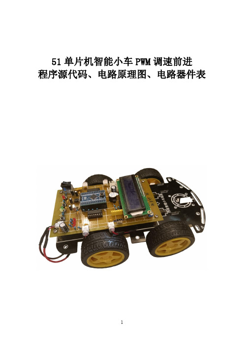
51单片机智能小车PWM调速前进程序源代码、电路原理图、电路器件表从控制电路角度划分,智能小车电路板分为核心板和驱动板。
核心板上的处理器的芯片型号是:STC15W4K56S4,这是一款51单片机。
驱动板上有电源电路、电机驱动电路以及一些功能模块接口。
智能小车前进只要控制智能小车四个轮子向前转动就可以了。
智能小车四个轮子由四个直流减速电机驱动。
直流减速电机驱动芯片采用L293D,一片电机驱动芯片L293D可以驱动两个直流减速电机,智能小车用到4个直流减速电机,需要用到两片L293D电机驱动芯片。
但有时候我们需要控制智能小车的速度,不希望智能小车全速前进。
比如在“智能小车循迹实验”中,如果智能小车速度过快,来不及反应做出方向的调整,智能小车会很容易跑离轨迹,这样就需要调整控制智能小车的速度了。
那么怎么样实现智能小车前进速度的调节呢?调节智能小车的速度,实际上是调节电机的运转速度,PWM调速是目前电机的主流调速方式。
智能小车采用脉宽调制(PWM)的办法来控制电机的转速,从而控制智能小车的速度。
在此种情况下,电池电源并非连续地向直流电机供电,而是在一个特定的频率下为直流电机提供电能。
不同占空比的方波信号,调节对直流电机的通断电,能起到对直流电机调速作用。
这是因为电机实际上是一个大电感,它有阻碍输入电流和电压突变的能力,因此脉冲输入信号被平均分配到作用时间上。
这样,改变L293D使能端EN1和EN2上输入方波的占空比就能改变加在电机两端的电压大小,从而改变了直流电机转速。
智能小车PWM调速前进程序如下:首先,定义了2个变量,这2个变量用于设置智能小车的速度。
unsigned char pwmval_left_init=6; //调节此值可以调节小车的速度。
unsigned char pwmval_right_init=6; //调节此值可以调节小车的速度。
通过以下函数初始化定时器0,每1毫秒中断一次。
void Timer0_Init(void) //定时器0初始化{TMOD=0x01;TH0=0xf8;TL0=0xcd;TR0=1;ET0=1;EA=1;}下面我们看定时器0的中断处理函数。
电机PWM调速原理演示程序

写CCR1寄存器即可随时改变占空比,从而改变电机功率。这种控
制方法功率损失很小(控制元件导通/截至都不耗电),效率高。
(C)西安电子科技大学 测控技术与仪器教研中心 编写:谢楷 2008/01/31
P1DIR |= BIT2; // P1.2 output
P1SEL |= BIT2; // P1.2 TA1 otions
TACTL = TASSEL_1 + MC_1; // ACLK, up mode
*/
//
//
// MSP430FE425
// -----------------
// | XIN|-
// | | 32kHz
// | XOUT|-
// | |
// | P1.2/TA1|----->三极管驱动--->小马达
// | (CCR1) | _ _ _ _
// | | _| |__| |__| |__| |_
{
CCR1++; //占空比不断提高
if(CCR1>=500) SpeedMode=1; //到达100%后转为减速模式
}
if(SpeedMode==1) //减速模式下
{
CCR1--; //占空比不断降低
// | | 40%~100% PWM
//
#include <MSP430X42X.h>
void Sys_Init()
{
WDTCTL=WDTPW+WDTHOLD; //停止看门狗
FLL_CTL0|=XCAP18PF; //配置晶振负载电容
PWM可逆直流调速系统设计

PWM可逆直流调速系统设计1. 引言PWM(脉冲宽度调制)可逆直流调速系统是一种常用的电机调速系统,广泛应用于工业生产和家电领域。
本文将介绍PWM可逆直流调速系统的设计原理、主要组成部分以及工作原理。
2. 设计原理PWM可逆直流调速系统的设计原理基于脉冲宽度调制技术和电机控制原理。
通过调整PWM信号的脉冲宽度,可以控制电机的转速和运行方向。
主要原理包括: - 电源供应:系统通过电源为电机提供电能。
- PWM信号生成:通过数字控制器或单片机产生PWM 信号。
- H桥驱动电路:将PWM信号转换为适合电机的驱动信号。
- 电机控制:根据PWM信号调整电机的转速和运行方向。
3. 主要组成部分PWM可逆直流调速系统主要由以下几个组成部分构成:3.1 电源供应电源供应是系统的功率来源,可以选择直流电源或交流电源。
直流电源常用的电压范围为12V或24V,交流电源则需要将交流电转换为直流电。
3.2 PWM信号生成PWM信号生成是通过数字控制器或单片机来产生PWM信号的过程。
通过控制PWM信号的占空比,可以改变电机的转速。
3.3 H桥驱动电路H桥驱动电路是将PWM信号转换为适用于电机驱动的信号的关键部分。
H桥由4个开关管组成,根据PWM信号的输入情况控制开关管的导通与关闭,从而改变电机的转速和运行方向。
3.4 电机控制电机控制是根据PWM信号调整电机的转速和运行方向的过程。
通过增大或减小PWM信号的占空比,可以控制电机的速度;通过改变PWM信号的极性,可以改变电机的运行方向。
4. 工作原理PWM可逆直流调速系统的工作原理如下:1.首先,电源供应向系统提供电能,为后续的电机驱动做准备。
2.数字控制器或单片机根据预设的参数生成PWM信号,并将其输入到H桥驱动电路。
3.H桥驱动电路根据PWM信号的输入情况控制开关管的导通与关闭,从而改变电机的转速和运行方向。
4.电机控制模块根据PWM信号的占空比调整电机的转速,根据PWM信号的极性改变电机的运行方向。
PWM调速程序
// Target : M16
// Crystal: 8.0000Mhz
#include <iom16v.h>
#include <macros.h>
void port_init(void)
{
PORTA = 0x00;
DDRA = 0x01;//set PA0 as PWM wave output port
}
#pragma interrupt_handler timer1_ovf_isr:9
void timer1_ovf_isr(void)
{
//TIMER1 has overflowed
TCNT1H = 0x00; //reload counter high value
TCNT1L = 0x00; //reload counter low value
TCCR1A = 0x01;
TCCR1B = 0x0C; //start Timer
}
#pragma interrupt_handler timer1_compa_isr:7
void timer1_compa_isr(void)
{
//compare occured TCNT1=OCR1A
PORTA&=~(1<<PA0); // clear PA0
void timer1_init(void)
{
TCCR1B = 0x00; //stop
//set initial value for counter
TCNT1H = 0x00; //setup
TCNT1L = 0x00;
- 1、下载文档前请自行甄别文档内容的完整性,平台不提供额外的编辑、内容补充、找答案等附加服务。
- 2、"仅部分预览"的文档,不可在线预览部分如存在完整性等问题,可反馈申请退款(可完整预览的文档不适用该条件!)。
- 3、如文档侵犯您的权益,请联系客服反馈,我们会尽快为您处理(人工客服工作时间:9:00-18:30)。
}
void speed_adjust(unsigned int speed)
{OCR1Al=speed;}// change compare value
//
void main(void)
{
init_devices();
//insert your functional code here...
While(1);
//TIMER1 initialize - prescale:256
// WGM: 5) PWM 8bit fast, TOP=0x00FF
// desired value: 100Hz
// actual value: 122.070Hz (18.1%)
//note:there is no particular requirement for the frequency of PWM wave as long as it is not too //low.
void timer1_init(void)
{
TCCR1B = 0x00; //stop
//set initial value for counter
TCNT1H = 0x00; //setup
TCNT1L = 0x00;
//set compare value
OCR1AH = 0x00;
OCR1AL = 0xFF;//
PORTB = 0x00;
DDRB = 0x00;
PORTC = 0x00; //m103 output only
DDRC = 0x00;
PORTD = 0x00;
DDRD = 0x00;
}
//note: even if you use the second function of PD4,PD5 as PWM wave output ports, you should //also set port’s direction.
port_init();
timer1_init();
MCUCR = 0x00;
GICR = 0x00;
TIMSK = 0x14; //timer interrupt sources
SEI(); //re-enable interrupts
//all peripherals are now initialized
TCCR1A = 0x01;
TCCR1B = 0x0C; //start Timer
}
#pragma interrupt_handler timer1_compa_isr:7
void timer1_compa_isr(void)
{
/compare occured TCNT1=OCR1A
PORTA&=~(1<<PA0); // clear PA0
PWM调速程序
假设在硬件电路已经连接好后,要控制直流电机的转速可以通过在电机驱动电路的使能端输入一PWM波形。改变PWM波的脉宽(占空比)即可改变加在电机两端的有效电压,从而改变电机的转速。注意,此处的PWM波只是相当于电机供电电路开关的作用:高电平对应接通,低电平对应断开。
对于Atmega 16单片机,这里利用T/C1定时器中断来产生PWM波形。在ICC AVR编译环境下,利用tool菜单中的application builder生成一个简单的PWM波程序。这段程序以PA0作为PWM波的输出端口。利用T/C1定时器比较匹配和溢出产生两次中断来改变PA0的输出电平。具体过程为:计数器TCNT1从初始值开始不断计数,当发生比较匹配时,把PA0置为低电平,计数器继续计数,当发生溢出中断时,计数器回到初始设定值,并把PA0置为高电平。从而在PA0端口获得一稳定持续的PWM波形,在主程序中改变比较值,即可改变波形占空比,而频率不变。
}
//note: when using the applocation builder tool , some sentences oftheautomaticly produced//program are not necessary for certain use like PWM wave ,delete them.
PORTA|=(1<<PA0) ;//set PA0
}
//call this routine to initialize all peripherals
void init_devices(void)
{
//stop errant interrupts until set up
CLI(); //disable all interrupts
}
#pragma interrupt_handler timer1_ovf_isr:9
void timer1_ovf_isr(void)
{
//TIMER1 has overflowed
TCNT1H = 0x00; //reload counter high value
TCNT1L = 0x00; //reload counter low value
//ICC-AVR application builder
// Target : M16
// Crystal: 8.0000Mhz
#include <iom16v.h>
#include <macros.h>
void port_init(void)
{
PORTA = 0x00;
DDRA = 0x01;//set PA0 as PWM wave output port
