RMZ说明书35-170~300-970
人民电器 赢领 RDM5Z系列剩余电流保护断路器 使用说明书

目 录RDM5Z剩余电流动作断路器RDM5Z剩余电流动作断路器(数码型)2 22…………………………………........................RDM5Z剩余电流动作断路器(光伏型) (42)SERIESR D M5Z系列剩余电流保护断路器符合标准:G B/T14048.2产品安装使用前,请仔细阅读使用说明书,警告:1 绝缘测试本断路器出厂前已按标准规定进行绝缘测试,因断路器带有电子线路板,不允许进行任何形式绝缘耐压测试。
2 断路器对同时接触被保护电路两线引起的触电危险不能进行保护,使用时请务必注意。
3 断路器进行动作特性试验时,应使用经国家有关部门检测合格的专用测试台,严禁利用相线直接触碰接地装置来测试剩余电流动作特性和相线与相线、相线与中性线之间短接来测试短路保护特性的试验方法。
4 严禁湿手操作断路器,否则可能发生电击事故。
5 漏电报警功能启动时,若检测到漏电故障后只报警不脱扣。
6 断路器负荷侧的N线,只能作为中性线,不得与其他回路共用,且不能重复接地。
注意1 断路器安装场所应无爆炸危险、无腐蚀性气体,并应注意防潮、防尘、防震动。
2 断路器安装位置应避开强电流电线和电磁器件,避免磁场干扰。
3 断路器上"N"接线端子必须接入中性线,以利于电子线路正常工作。
安装时必须严格区分中性线(N)和保护线(PE),经过断路器的中性线不得作为保护线,不得重复接地或接设备外露可导电部分。
保护线不得接入断路器。
4 断路器的漏电、过载、短路、欠过压等保护特性均由制造厂整定,在使用中不可随意调整,以免影响性能。
5 远程控制"分闸、合闸"端子严禁外接电源,只能接入"分"或"合"无源按钮通合信号。
所有的远程控制和信号传输连接线应尽量采用屏蔽电缆线以增强抗干扰能力。
6 本断路器内部虽已经设计有抗雷击措施,但对于雷电频繁、冲击电压过高的雷电高发地区,建议在漏电断路器前端线路加装避雷器保护。
ZP35压片机使用说明书(1)
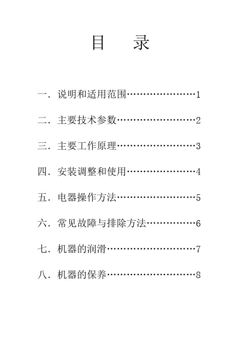
目录一.说明和适用范围 (1)二.主要技术参数 (2)三.主要工作原理 (3)四.安装调整和使用 (4)五.电器操作方法 (5)六.常见故障与排除方法 (6)七.机器的润滑 (7)八.机器的保养 (8)安装前、开机前、维修前,必须仔细阅读本说明书,说明书内不推荐的行为均可能引起机器的异常或人身安全。
一.用途说明和适用范围1.本机是根据生产用自动旋转、连续压片的压片机微型化的机器,它主要用于制药、化工、食品、电子等工业部门工艺研究,确认颗状原料能否压制成片剂的重要设备。
2.本机适用于能压制成片剂(本机压力范围内)的。
而且含粉量(100目以上)不超过10%的颗粒状原料的压制。
3.本机适用于压制5-20毫米的圆形、异形和刻字片剂。
4.本机不适用于半固体、潮湿颗粒、低熔点易吸潮原料和无颗粒的粉末压片。
二.主要技术参数三.工作原理与主要机构1.转台结构:转台是本机工作的主要执行件。
有上、下轴承组件、主轴、转台等主要零件构成。
转台的圆周上均匀分布35付冲模,转台与主轴间由平键传递扭矩。
主轴支撑在轴承上,由蜗轮副传动,花键连接,转动主轴,使转台旋转工作。
2.轨道机构:轨道有上轨道和下轨道组成的圆柱凸轮和平面凸轮,是上、下冲杆运动的轨迹。
上轨道由上冲上行轨、上冲下行轨、上冲上平行轨、上冲下平行轨、压下路轨等多块轨道组成。
它们分别紧固在上轨道盘上。
下轨道由上冲下行轨、下冲上行轨和充填轨组成。
它们分别安装在下轨道座上。
3.充填调节装置:充填调节作用于调节片剂重量。
充填调节机构装置在主体的内部,在主体的平面上可观察到月形的充填轨,它由螺旋的作用而上升或下降来控制充填量,转动圆盘调节时,顺时针充填量减少,反之加大。
4.片厚(压力)调节装置:通过调节下压轮上下来调节片厚(压力)。
下压轮装在主体的槽内,它套在偏心轴上,外端连接在手轮上,当外部手轮调节时,偏心轴带动压轮上升或下降,即调节片厚(压力)。
借以控制片剂的厚度和硬度。
布兹斯曼系列ATM小型刀片断路器产品说明说明书

ATM blade fusesCatalog symbol•ATM-_DescriptionA range of UL ® Listed fast-acting miniature blade fuses for automotive and low-voltage circuits.Ratings• Volts: 32 Vac/dc • Amps: 2 to 30 A •Interrupting rating: 1 kAAgency information• UL Listed, Guide FHXT , File AU169•ISO 8820-3 / JASO D612 / SAE J2077 and J1171 ignition protectionMaterials• Silver-plated zinc terminals and element •Polyamide housing with UL 94 HB flammabilityratingEnvironmental•Operating temperature range -40°C to +80°C, 95% RH non-condensing•Storage temperature range -5°C to +35°C or lower, 85% RH non-condensingBasic catalog numbersATM-2Gray ATM-15Blue ATM-3Violet ATM-20Y ellow ATM-4Pink ATM-25Clear ATM-5Tan ATM-30GreenATM-7-1/2Brown* Available only in traditional and bulk pack.Packaging codesReload ATM-(amp)RLD*10 fuses in a polybag Retail pack BP/ATM-(amp)-RP 5 fuses in a blister card Value pack VP/ATM-(amp)-RP 25 fuses in a clamshell packBulk packBK/ATM-(amp)500 fuses in a carton* Not available for the 4 amp ATM fuses.Dimensions — inOperating @ 23°C*135%0.75 sec 600 sec 160%0.25 sec 50.0 sec 200%0.15 sec 5.0 sec 350%0.04 sec 0.5 sec 600%0.02 sec0.1 sec* Fuse characteristics may vary according to the conditions under which they are used. Fuse derating with change in ambient temperature: -0.15% / 1°C.Features• Halogen free and RoHS compliant •Test points on fuse housing speeds troubleshooting•Industry standard color coded by amp ratingT ypical applications• Automotive•Low voltage control circuitsRecommended fuse holders, add-a-circuit and fuseclipsHHH additional fused circuit on a block 32V/10A 5”/#16HHLInline fuse holder with cover 32V/20A 2x4”/#16HHM Inline fuse holder with cover 32V/30A 2x4”/#12HHU Water resistant inline fuse holder with cover32V/30A 2x4”/#12ATM-FHIDIndicating inline fuse holder with cover 32V/20A 2x4”/#161A5778**PCB fuse clip 32V/15A —1A5779**PCB fuse clip with nylon base32V/15A—** See data sheet no. 2131 for details.HALOGENHF FREEATM blade fusesTechnical Data 2048Effective May 2021Eaton and Bussmann are valuable trademarks of Eaton in the US and other countries. Y ou are not permitted to use the Eaton trademarks without prior written consent of Eaton.Eaton1000 Eaton Boulevard Cleveland, OH Bussmann Division 114 Old State Road Ellisville, MO 63021United States/bussmannseries© 2021 EatonAll Rights Reserved Printed in USAPublication No. 2048 — BU-SB15054May 2021Follow us on social media to get thelatest product and support information.For Eaton’s Bussmann series product information,call 1-855-287-7626 or visit:/bussmannseriesThe only controlled copy of this data sheet is the electronic read-only version located on the Eaton network drive. All other copies of this document are by definition uncontrolled. This bulletin is intended to clearly present comprehensive product data and provide technical information that will help the end user with design applications. Eaton reserves the right, without notice, to change design or construction of any products and to discontinue or limit distribution of any products. Eaton also reserves the right to change or update, without notice, any technical information contained in this bulletin. Once a product has been selected, it should be tested by the user in all possible applications.Time-current characteristic curves — average meltT i m e i n s e c o n d sCurrent in amps1 A15 A10 A7-1/2 A5 A 4 A 3 A 2 A20 A 25 A30 A 1109876543210010000.010.1110,000100010010Electrical characteristics249.7 m Ω140 mV 329.6 m Ω140 mV 423.8 m Ω136 mV 5 A 16.7 m Ω112 mV 7-1/211.1 m Ω112 mV 107.82 m Ω106 mV 15 4.93 m Ω99 mV 20 3.48 m Ω95 mV 25 2.58 m Ω92 mV 302.12 m Ω86 mVR E R A T I N G F A C T O R (% A M P E R E R A T I N G )-50 -40-30-20-10102030405060708090100110120 130758085909510010511011512070AMBIENT TEMPERATURE (˚C)T emperature rerating curve。
人民电器 RDM5Z系列剩余电流保护断路器 选型手册说明书
完善的产业链和个性化解决方案,满足全球客户的不同需求!人民电器集团是人民控股集团全资公司,中国500强企业之一,始创于1986年。
人民电器集团以工业电器为核心产业,拥有浙江、上海、南昌、抚州、枣庄、合肥六大制造基地、35家全资子公司150家控股成员企业、1500多家加工协作企业和5000多家销售公司。
产品畅销全球125个国家和地区,广泛应用于浦东机场、京沪高铁、三峡水电、北京地铁、奥运场馆南水北调、青藏铁路、嫦娥探月工程、越南太安水电枢纽等国内外重大工程项目,位居世界机械企业500强前列。
2023年,经世界品牌实验室测评,品牌价值788.15亿。
公司简介COMPANY PROFILE更 安 全保障人员生命及财产安全。
更 可 靠不间断供应电力,全天随时可用。
更 高 效降低能源消耗和成本,提高生产率,缩短需求供应时间。
优化机械、工厂流程,提高使用舒适性。
更 经 济更 环 保通过可再生能源提供能量,减少二氧化碳排放量。
电力与能源电力石油石化交通工业与机器矿业/建材水利/水处理汽车数据中心IT高科技互联网商业网络银行保险金融机构电信运营楼宇办公楼宇工业建筑基础设施住宅住宅建设公共建设小区设施剩余电流保护断路器逆变器直流断路器直流塑壳断路器直流框架断路器光伏箱变直流熔断器直流浪涌保护器终端新能源RDM5L系列剩余电流保护断路器G-092RDM5系列塑料外壳式断路器G-044RDB5-125系列小型断路器G-163RDM5Z系列剩余电流保护断路器G-120RDQH5系列双电源自动转换开关G-142RDB5-80S系列预付费小型断路器G-162RDB5系列小型断路器G-151RDB5-63系列小型断路器G-160RDW5系列万能式断路器G -001RDM5E系列电子式断路器G-065RDXQ5系列双电源自动转换开关G-138RDB5-80系列小型断路器G-161RDB5-40系列小型断路器G-159RDQ5系列双电源自动转换开关G-147RDHM5系列剩余电流保护断路器G-103RDB5-125S系列小型断路器G-164RDB5LE-40系列剩余电流动作断路器G-172RDB5LE-63Y系列一体式剩余电流动作断路器G-184RDB5GS系列隔离开关G-170RDB5LE-100系列剩余电流动作断路器G-178RDB5LE-63MA系列剩余电流动作断路器G-174RDB5-125H系列小型断路器G-167RDB5LE-63系列剩余电流动作断路器G-173RDB5GQ系列自恢复式过欠压保护器G-186RDB5LE-32系列剩余电流动作断路器G-171RDB5LE-125H系列剩余电流动作断路器G-181RDB5LEs-63系列剩余电流动作断路器G-176RDQH5Y系列双电源自动转换开关G-147G-191RDU5Z系列电涌保护器RDR5系列热过载继电器G-197RDJ5系列电磁继电器G-203RDC5系列交流接触器G-192RDCJ5系列接触式继电器G-201RDS5系列电动机保护断路器G-205RDU5系列电涌保护器G-189RDSCB系列电涌保护器G-188正常工作条件和环境适应性□ □ 海拔高度:2000m□ 电磁干扰:适用于电磁环境A □ 使用类别:B类□ 污染等级:污染等级为3级□ 安装级别:断路器主电路、欠电压脱扣器线圈、智能控制器的电源变压器初级线圈 为IV ,控制电路、辅助电路为III□ 防护等级:IP20 (当断路器安装在柜体室内,且加装门框后,防护等级能达到IP40)□ 储存条件:-25~+55℃□ 运输条件:应轻拿轻放,不应倒置,避免剧烈碰撞环境温度:周围空气温度为-5~+40℃,24h 的平均值不超过+35℃产品概述RDW5系列万能式断路器适用于交流50/60HZ ,额定工作电压AC400V/690V ,额定电流至6300A 以下的配电网络中,主要用作配电、馈电和发电保护,使线路及电源设备免受过载、欠电压、过电压、电流电压不平衡、短接和接地/漏电等故障的危害。
MRZ操作使用说明书
用户使用说明书不含电控部分1.综述祝贺你选择了MRZ1400 MR60型环式刨片机! MRZ1400 MR60是高技术和高质量性价比整合的产物它已被多方面长时间的证明MRZ是欧洲共同体相同产品中的领行者1.1生产商申明1.2概要◆本使用手册必须要由掌握机械知识的人才能正确使用;◆本使用手册包含:安全运行设备和适当使用及经济使用的重要信息;◆你的专注有助于你积极的使用设备,以免危险的发生;◆适时的养护和正确的使用有利于设备获得长的使用年限;◆这个使用手册是新增操作者必需使用的,并基于相关的法规,预防意外的发生,保证设备正常使用的全过程;并用于对人员的保护;◆操作能力的提高,使企业主能掌握生产现场的安全,并以作为投保的依据;技术上的进步和改进将不能全部在说明书中反映!◆如果机器被转卖, 说明书或手册应当随机器交给新的购买者;◆当新的购买者在使用设备前,一定要求新购买者阅读这些说明书或手册;1.3安全信息1.3.1一般规则操作者应当是有机械知识和操作经验的人;在操作者前一定要先阅读说明书,并在工作过程中尊重它, 操作者应当掌握以下知识:◆预防安全事故发生的规章;◆公认的安全技术规范;◆国标和行业标准;◆企业的安全规范;◆操作者必须确定掌握最新的技术和安全知识;◆上面提及的规章必须是最新的版本;1.3.2安装及使用对不按操作说明书,而是出于经验习惯操作造成的机器损坏,迈耶公司将不承担保质责任;操作者有责任按操作手册,对设备进行维护并确保设备的安全运行;在设备使用.保养和维护中遵守操作手册中的规定是使设备正常工作的关键;1.3.3人员要求操作人员必须具备以下的各项技能:◆必须具有机械操作的资格和经验,最好能通过了机械生产厂商的确认;◆安装、维护、保养等工作,必须要使用有资格的机械工程师来完成;◆人员最好受过专门的培训,对意外的危害和危险有适当的认知,并熟悉安全手册的要求。
1.3.4备品备件不能使用非原厂的易损件,质量不确定的代用品不能保证设备使用中的安全性;安全保护设施不能去掉和使用不可靠部件;使用的备件要是设备厂家推荐的可靠备件,否则使用不当者将承担使用非正品备件所引起的一切责任;1.3.5安全标识符号定义意义阅读文件无论如何都要仔细阅读设备厂商提供的文件交付的图表无论如何都要注意电路图等图表警告危险警告,不正确的使用会导致设备的损失警告危险警告,不正确的使用会导致人员的损伤有势能的物体将持续出现周围环境有敏感变化,对人可能产生损害,请远离机械损伤警告危险警告,不正确的使用将对人员的手掌部位造成伤害以上的这些标识在接触设备前,必须要能识别和明了含意1.3.6大部分重要安全防范概念安全防范和保护是保护人员及设备安全的保证,所以必须遵守;它不单是包含设备的附带文件,还要附含当地的法规及相关规定;◆设备最好只用于先前确定的目的;◆进料系统和出料系统都要和刨片机匹配;◆要坚持遵守安全规则和相关的规定;◆决不能移除设备本身所附带的安全防护设施;◆保证设备在额定负荷内工作;◆决不能在没有设备厂商参与的情况下改造设备;◆一定要用有执业资格的专业人员来对设备进行安装.维护和保养;◆保证所有操作人员都阅读和了解操作手册;◆保证所有操作人员都遵守操作手册;◆保证所有维护都按操作手册进行定期维护;◆保证所有操作人员都对机械设备的构造都清楚了解;◆最好使用原厂零配件;◆在设备保养时无论如何都不能用切断总电源的方式来进行,因为这样会使设备上的安全保障装置失灵;◆除操作说明书外,各种安全规则和当地的安全法规也要被遵守,使用者也应遵守被认可的技术规程,并是专业人员;◆如机器处于有可能发生粉尘爆炸的环境中,购买者要事先告知设备厂商;◆在未使进料系统停止时,使用急停装置会对转子造成损害;◆在刀环取出机腔的过程中,要使用专用的起吊装置和吊钩,把刀环从机器上起吊并转运到专用的刀环运输车上;◆应当使用专用的刀环运输车来运输刀环;◆要使环式刨片机保持清洁,如必要的话可以使用防护;◆检查液压系统;◆液压系统是一个独立的系统,液压液要使用耐高温且高燃点的被推荐产品;◆在液压系统起动前要先检查,整个系统必须处于没有处于压力可能骤变或压力集中的条件中’◆链式提升机起吊的重量一定要在额定起吊重量以下;◆操作链式提升机的人员必须是有资格的人员;◆出于安全,操作人员应配戴保护听力的耳塞;◆接触电路的人员必须持有相应的电工证;1.3.7设备使用企业必备的条件◆电机.电缆必须要有防止人为意外损坏的防护;◆人员和设备之间要有一个安全距离;◆一定要对设备的振动有所防止;◆设备上的磁体和人员之间要有一个安全距离,特别是对使用心脏起博器的人员可能带来生命危险;◆磁性物质的分离器要防止意外碰撞,应当标识警告标识;◆如可能如液压等可能被损伤或可能损伤人员的装置也能标识警告标识; ◆必须对电路的短路和断路进行防止;◆紧急停机和起动必须要有专门的高级别专业人员来负责;◆万一发生生产线紧急事故,必须由专业人员对所有系统.设备及部件和工位进行检查和清理并对损坏的部份进行维护后方能在专业人员的监督下起动生产线;2.产品说明2.1使用MRZ1400 MR60型环式刨片机是专门用来生产刨花的(木片的长度不应超过60毫米)。
E3Z-光电开关说明书
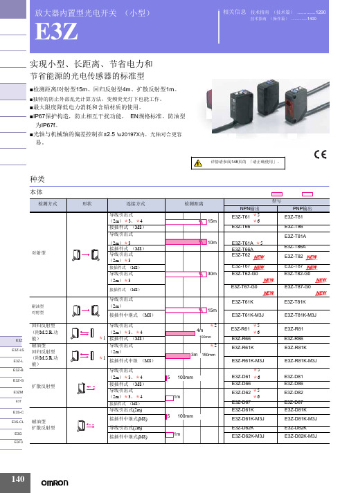
放大器内置型光电开关 (小型)E3Z实现小型、长距离、节省电力和节省能源的光电传感器的标准型■检测距离/对射型15m 、回归反射型4m 、扩散反射型1m 。
■独特的防止外部乱光计算方法,变频荧光灯下也能工作。
■最大限度降低电力消耗和含铅材质的使用。
■IP67保护构造,防止相互干扰功能, EN 规格标准。
防油型 为IP67f 。
■光轴与机械轴的偏差控制在±2.5°\u20197X 内,光轴对合更容 易。
种类相关信息 技术指南 (技术篇) (1290)技术指南 (操作篇) (1400)E3Z 注. 防油型号的回归反射型与标准的回归反射型检测距离不同。
*1. 不附带反射板,根据不同用途,有7种反射板可供选择购买。
*2. 检测距离是使用E39-R1S 时距离。
另外传感器与反射板间的距离请设定在 []内的数值以上的范围。
*3. 上表中标有*3的产品表示有导线0.5m 也是标准品,请在型号末尾标明导线长度。
(例:E3Z-T61 0.5M ) *4. 上表中标有*4的产品表示有接插件中继型 (M12)型号末尾带有-M1J 。
(例:E3Z-T61-M1J ) *5. 上表中标有*5的产品表示e-CON 接插件中继型。
(导线长度0.3m/0.5m/2m )。
型号末尾带有-ECON 。
例如E3Z-□6□-ECON 。
详细情况请参照1381页。
连接接插件有单面e-CON 接插件 E39-ECON □ (导线长度2m/5m )和两端e-CON 接插件 E39 -ECONW □ (导线长度0.5~2m 0.1m 单位) 2种。
e-CON 是FA 设备、连接器制作商的标准化规格。
*6. 备有夹紧式e-CON 接插件中继型 (导线长度2m ) 。
型号末尾带有-ECON-C (例:E3Z-T61-ECON-C 2M ) 。
接插件有单侧e-CON 接插件型 E39-ECON □M (导线长度2m/5m ) 和两端e-CON 接插件型 E39-ECONW □ (导线长度0.5~2m 0.1m 为单位)。
艾森 Moeller 系列 Z5 超压保护器说明说明书

Eaton 210071Eaton Moeller® series Z5 Overload relay, Ir= 70 - 100 A, 1 N/O, 1N/C, For use with: DILM250Spécifications généralesEaton Moeller® series Z5 Thermaloverload relay2100714015082100711146 mm167 mm128 mm 1.727 kgCSA Class No.: 3211-03UL Category Control No.: NKCR VDE 0660CSA-C22.2 No. 60947-4-1-14 CSAUL 60947-4-1CSA File No.: 012528IEC/EN 60947-4-1CEIEC/EN 60947ULUL File No.: E29184Z5-100/FF250Product Name Catalog NumberEANProduct Length/Depth Product Height Product Width Product Weight Certifications Model Code100 A2 x (0.75 - 2.5) mm², Control circuit cables1 x (0.75 - 2.5) mm², Control circuit cablesIs the panel builder's responsibility. The specifications for the switchgear must be observed.8 mm25 °CMeets the product standard's requirements.Is the panel builder's responsibility. The specifications for the switchgear must be observed.Direct mountingDirect attachmentSeparate mountingDoes not apply, since the entire switchgear needs to be evaluated.40 °CMeets the product standard's requirements.AutomaticPush-button10 kA, SCCR (UL/CSA)400 A, max. CB, SCCR (UL/CSA)400 A Class J, max. Fuse, SCCR (UL/CSA)Is the panel builder's responsibility.eaton-tripping-z5-overload-relay-characteristic-curve-003.epseaton-tripping-z5-overload-relay-characteristic-curve.epsDA-DC-00004856.pdfDA-DC-00004846.pdfETN.Z5-100_FF250IL03407081ZIL03407006ZIL03407139ZDA-CS-z5_ff250DA-CD-z5_ff250eaton-tripping-devices-overload-relay-z5-overload-relay-dimensions-002.epseaton-tripping-devices-overload-relay-z5-overload-relay-3d-drawing.epseaton-tripping-devices-overload-relay-zeb-overload-relay-wiring-diagram.epsRated operational current for specified heat dissipation (In) Terminal capacity (flexible with ferrule)10.11 Short-circuit ratingStripping length (control circuit cable)Ambient operating temperature (enclosed) - min10.4 Clearances and creepage distances10.12 Electromagnetic compatibilityMounting method10.2.5 LiftingAmbient operating temperature (enclosed) - max10.2.3.1 Verification of thermal stability of enclosures Reset functionShort-circuit current rating (basic rating)10.8 Connections for external conductors Characteristic curve Declarations of conformity eCAD model Instructions d'installation mCAD modelSchémasSchémas électriquesM10 x 35, Terminal screw, Main connectionsM3.5, Terminal screw, Control circuit cablesAdjustable current range - min70 ATerminal capacity (flexible with cable lug)185 mm²ProtectionWith terminal cover, Protection against direct contact when actuated from front (EN 50274)Ambient operating temperature - max60 °CClimatic proofingDamp heat, constant, to IEC 60068-2-78Damp heat, cyclic, to IEC 60068-2-30FeaturesTrip-free releasePhase-failure sensitivity (according to IEC/EN 60947, VDE 0660 Part 102)Test/off buttonReset pushbutton manual/autoStatic heat dissipation, non-current-dependent Pvs0 WElectrical connection type of main circuitScrew connection10.9.3 Impulse withstand voltageIs the panel builder's responsibility.Voltage rating - max600 VACTerminal capacity (busbar)25 mm width, Main connectionAmbient operating temperature - min-25 °C10.6 Incorporation of switching devices and componentsDoes not apply, since the entire switchgear needs to be evaluated.10.5 Protection against electric shockDoes not apply, since the entire switchgear needs to be evaluated.240 V AC, Between auxiliary contacts, According to EN 61140 500 V AC, Between main circuits, According to EN 61140440 V, Between auxiliary contacts and main contacts, According to EN 61140Rated operational current (Ie) at AC-15, 220 V, 230 V, 240 V1.5 AClassCLASS 10 A10.13 Mechanical functionThe device meets the requirements, provided the information in the instruction leaflet (IL) is observed.10.2.6 Mechanical impactDoes not apply, since the entire switchgear needs to be evaluated.10.9.4 Testing of enclosures made of insulating materialIs the panel builder's responsibility.Number of contacts (normally closed contacts)110.3 Degree of protection of assembliesDoes not apply, since the entire switchgear needs to be evaluated.Rated operational current (Ie) at AC-15, 380 V, 400 V, 415 V0.9 AHeat dissipation per pole, current-dependent Pvid7.9 WProduct categoryOverload relay Z5Overload release current setting - min70 ARated operational current (Ie) at DC-13, 60 V0.75 AEquipment heat dissipation, current-dependent Pvid23.7 WHeat dissipation capacity Pdiss0 WSuitable forBranch circuits, (UL/CSA)Terminal capacity (stranded with cable lug)185 mm²Temperature compensationContinuous≤ 0.25 %/K, residual error for T > 40°Terminal capacity (solid)2 x (0.75 - 4) mm², Control circuit cables1 x (0.75 - 4) mm², Control circuit cablesNumber of auxiliary contacts (normally closed contacts)110.2.3.2 Verification of resistance of insulating materials to normal heatMeets the product standard's requirements.10.2.3.3 Resist. of insul. mat. to abnormal heat/fire by internal elect. effectsMeets the product standard's requirements.Width across flats16 mm (Hexagon head spanner SW)Rated operational current (Ie) at DC-13, 220 V, 230 V0.2 AConventional thermal current ith of auxiliary contacts (1-pole, open)6 AOverload release current setting - max100 ATerminal capacity (solid/stranded AWG)2/0 - 500 MCM, Main cables2 x (18 - 14), Control circuit cables10.9.2 Power-frequency electric strengthIs the panel builder's responsibility.Degree of protectionIP00Overvoltage categoryIIINumber of auxiliary contacts (change-over contacts)Pollution degree310.7 Internal electrical circuits and connectionsIs the panel builder's responsibility.Rated impulse withstand voltage (Uimp)4000 V (auxiliary and control circuits)8000 V AC10.10 Temperature riseThe panel builder is responsible for the temperature rise calculation. Eaton will provide heat dissipation data for the devices.Tightening torque1.2 Nm, Screw terminals, Control circuit cables18 Nm, Main cable connection screw/boltAdjustable current range - max100 AScrewdriver size2, Terminal screw, Control circuit cables, Pozidriv screwdriver 1 x 6 mm, Terminal screw, Control circuit cables, Standard screwdriverRated operational current (Ie) at AC-15, 120 V1.5 A10.2.2 Corrosion resistanceMeets the product standard's requirements.10.2.4 Resistance to ultra-violet (UV) radiationMeets the product standard's requirements.10.2.7 InscriptionsMeets the product standard's requirements.Number of contacts (normally open contacts)1Short-circuit protection ratingMax. 6 A gG/gL, fuse, Without welding, Auxiliary and control circuits200 A gG/gL, Fuse, Type “2” coordination315 A gG/gL, Fuse, Type “1” coordinationNumber of auxiliary contacts (normally open contacts)1Rated operational current (Ie) at DC-13, 110 V0.4 ARated operational voltage (Ue) - max1000 VShock resistanceEaton Corporation plc Eaton House30 Pembroke Road Dublin 4, Ireland © 2023 Eaton. Tous droits réservés.Eaton is a registered trademark.All other trademarks are property of their respectiveowners./socialmedia10 g, Mechanical, Sinusoidal, Shock duration 10 ms 0.9 AR300, DC operated (UL/CSA)B300 at opposite polarity, AC operated (UL/CSA) B600 at opposite polarity, AC operated (UL/CSA)Rated operational current (Ie) at DC-13, 24 V Switching capacity (auxiliary contacts, pilot duty)。
壮大的Cat 352F LRE 长达达机械说明书

352F LRE Hydraulic ExcavatorIntroductionThe Cat 352F LRE machine is built to keep your production numbers up and your owning and operating costs down. The real power comes from the enhanced hydraulic system, which allows youto move tons of material all day long with a great dealof speed and precision. When you add in a quiet operator environment that keeps you comfortable and productive, service points that make your routine maintenance easy, and multiple Cat work tools that help you take on a variety of jobs, you simply won’t find a better long reach excavation machine.ContentsKey Features (2)Specifications (4)Standard Equipment (12)Optional Equipment (13)Notes ...................................................................14Performance• The C13 ACERT engine meets U.S. EPA Tier 4 Final and EU Stage IV emission standards.• Automatic engine speed control lowers rpm based on load for reducedfuel consumption.• Power modes help you more actively manage fuel consumption. Durable Structures• The boom and stick are built with internal baffle plates and are stress relieved for added durability; each undergoes ultrasound inspection to ensure quality and reliability.• Front linkage pins have thick chrome plating, giving them high wear resistance even under water.• Heavy-duty wide undercarriage provides a stable, rugged platform for long reach digging and loading applications.• Track shoes, links, rollers, idlers, and final drives are built with high-tensile strength steel.• Grease-lubricated track link protects moving parts by keeping water, debris, and dust out and grease sealed in to deliver longer wear life and reduced noise when traveling.• Optional guide guards help maintain track alignment to improve the machine’s overall performance – whether you’re traveling on a flat, heavy bed of rock or a steep, wet field of mud.Maintenance• Routine maintenance items like grease points and fluid taps are easy to reach at ground level.• The side-by-side cooling system enables easy cleaning.• Multiple S∙O∙S SM ports and pressure diagnostic taps help prevent maintenance downtime.Key Features Built-in benefits and available optionsComfort• The full-size cab is quiet and comfortable.• Seats are adjustable and feature air suspension and heated and cooled options.• The LCD monitor is easy to navigate and programmable in 44 languages.Versatility• Exclusive Cat attachments allow you totake on a variety of work – quickly andefficiently.• A Cat coupler lets you swap betweenattachments in seconds without leavingthe cab.• Optional Tool Control rememberspressures and flows for up to 20 toolsto enhance uptime.Safety• Smart refuel fills the machine quicklyfrom an external fuel source; itautomatically stops when the fuel tankis full or the fuel source is empty.• The rearview and sideview camerasenhance visibility to help makeoperators more efficient.• Anti-skid plates reduce slipping hazardsin all types of weather conditions.3EngineEngine Model Cat C13 ACERTGross Power – SAE J1995322 kW432 hp Engine Power – ISO 14396317 kW425 hp Net Power – ISO 9249304 kW408 hp Bore130 mm 5.1 in Stroke157 mm 6.2 in Displacement12.5 L763 in3Hydraulic SystemMain System – Maximum Flow (total)770 L/min203 gal/min Swing System – Maximum Flow385 L/min102 gal/min Maximum Pressure – Equipment35 000 kPa5,076 psi Maximum Pressure – Equipment(Lift mode)38 000 kPa5,511 psi Maximum Pressure – Travel35 000 kPa5,076 psi Maximum Pressure – Swing27 500 kPa3,989 psi Auxiliary Circuit – High Pressure300 L/min79 gal/min Auxiliary Circuit – Medium Pressure45 L/min12 gal/min Pilot System – Maximum Flow27 L/min7 gal/min Pilot System – Maximum Pressure4120 kPa598 psi Boom Cylinder – Bore170 mm 6.7 in Boom Cylinder – Stroke3748 mm147.6 in Stick Cylinder – Bore190 mm7.5 in Stick Cylinder – Stroke4306 mm169.5 inB1 Bucket Cylinder – Bore120 mm 4.7 inB1 Bucket Cylinder – Stroke2788 mm109.8 inAir Conditioning SystemThe air conditioning system on this machine contains the fluorinated greenhouse gas refrigerant R134a (Global Warming Potential = 1430). The system contains 1.00 kg of refrigerant, which has a CO2 equivalent of 1.430 metric tonnes.DriveMaximum Travel Speed 4.7 km/h 2.91 mph Maximum Drawbar Pull330 kN74,200 lbfSwingSwing Speed8.7 rpmMaximum Swing Torque187 kN·m137,924 lbf-ftService Refill CapacitiesFuel Tank Capacity720 L190 gal Cooling System50 L13.2 gal Engine Oil (with filter)38 L10 gal Swing Drive (each)10 L 2.6 gal Final Drive (each)15 L 4 gal Hydraulic System (including tank)570 L151 gal Hydraulic Tank407 L108 gal DEF Tank41 L11 galTrackNumber of Shoes (each side)52 piecesNumber of Track Rollers (each side)9 piecesNumber of Carrier Rollers (each side) 3 piecesSoundExterior Sound Power Level –ISO 6395:2008*106 dB(A)Operator Sound Pressure Level –ISO 6396:200869 dB(A)• Hearing protection may be needed when operating with an open operator station and cab (when not properly maintained or doors/ windows open) for extended periods or in a noisy environment.* As per European Union Directive 200/14/EC as amended by 2005/88/EC.352F LRE Hydraulic Excavator Specifications4352F LRE Hydraulic Excavator Specifications DimensionsAll dimensions are approximate.Boom Option LRE Boom11.5 m (37'9")Stick Option LRE Stick8.5 m (27'11")1Shipping Height*3740 mm12'3"2Shipping Length16 460 mm54'0"3Tail Swing Radius3760 mm12'4"4Length to Center of Rollers4340 mm14'3"5Track Length5380 mm17'8"6Ground Clearance, including Shoe Lug Height710 mm2'4"Ground Clearance, not including Shoe Lug Height740 mm2'5"7Track GaugeLong Variable Gauge Undercarriage (expanded)3720 mm12'3"Long Variable Gauge Undercarriage (retracted)3220 mm10'7"8Transport Width without StepsLong Variable Gauge Undercarriage (expanded)600 mm (24") Shoes4320 mm14'2"750 mm (30") Shoes4470 mm14'8"900 mm (35") Shoes4620 mm15'2"Long Variable Gauge Undercarriage (retracted)600 mm (24") Shoes3820 mm12'6"750 mm (30") Shoes3970 mm13'0"900 mm (35") Shoes4120 mm13'6"9Cab Height3390 mm11'2"10Counterweight Clearance**1450 mm4'9"Bucket Type GDBucket Part Number347-6708Bucket Capacity 1.19 m3 1.56 yd3 Bucket Tip Radius1557 mm5'1"*Including shoe lug height.**Without shoe lug height.5352F LRE Hydraulic Excavator Specifications6Working RangesAll dimensions are approximate.510152025303540455055606570Feet510152025303540455101520253035404550Feet1234567891112131415106789101112131454321Boom Option LRE Boom11.5 m (37'9")Stick Option LRE Stick8.5 m (27'11")1Maximum Digging Depth13 040 mm42'9" 2Maximum Reach at Ground Level19 640 mm64'5" Maximum Radius of Working Equipment19 790 mm64'11" 3Maximum Cutting Height14 700 mm48'3" 4Maximum Loading Height12 030 mm39'6" 5Minimum Loading Height2250 mm7'5"6Maximum Depth Cut for 2440 mm (8'0") Level Bottom12 600 mm41'4" 7Maximum Vertical Wall Digging Depth11 280 mm37'0" Bucket Digging Force (ISO)141 kN31,600 lbf Stick Digging Force (ISO)104 kN23,400 lbf Bucket Digging Force (SAE)125 kN28,000 lbf Stick Digging Force (SAE)103 kN23,100 lbf Bucket Type GDBucket Part Number347-6708Bucket Capacity 1.19 m3 1.56 yd3 Bucket Tip Radius1557 mm5'1"352F LRE Hydraulic Excavator Specifications7Operating Weights and Ground Pressures900 mm (35")750 mm (30")600 mm (24")Triple Grouser Shoes Triple Grouser Shoes Triple Grouser Shoes Operating Weights 59 400 kg 130,954 lb 58 600 kg 129,190 lb 57 800 kg 127,427 lb Ground Pressures69 kPa10.0 psi82 kPa11.8 psi101 kPa14.6 psiMajor Component Weightskg lb Base Machine (with boom cylinder, without counterweight, front linkage and track)29 84465,795Lower Structure (without track)Long Variable Gauge Undercarriage 14 50431,976Upper Structure (with boom cylinder, without front linkage and counterweight)For 12 mt (13.2 t) Counterweight 15 34033,818Counterweight 12 mt (13.2 t)12 00026,455Boom (includes lines, pins and stick cylinder)LRE Boom – 11.5 m (37'9")580012,787Stick (includes lines, pins and bucket cylinder)LRE Stick – 8.5 m (27'11")33007,275Track Shoes900 mm (35") Triple Grouser Shoes 670014,770750 mm (30") Triple Grouser Shoes 594013,095600 mm (24") Triple Grouser Shoes 519011,441BucketGD 1.19 m3 (1.56 yd3)7731,706Base machine includes 75 kg (165 lb) operator weight, 90% fuel weight, and undercarriage with center guard.352F LRE Hydraulic Excavator Specifications8LRE Fronts Capacities – Counterweight: 12 mt (13.2 t) – without Bucket – Heavy Lift: OnISO 10567* I ndicates that the load is limited by hydraulic lifting capacity rather than tipping load. The above loads are in compliance with hydraulic excavator lift capacity standard ISO 10567:2007. They do not exceed 87% of hydraulic lifting capacity or 75% of tipping load. Weight of all lifting accessories must be deducted from the above lifting capacities. Lifting capacities are based on the machine standing on a firm, uniform supporting surface. The use of a work tool attachment point to handle/lift objects, could affect the machine lift performance.Lift capacity stays with ±5% for all available track shoes.Always refer to the appropriate Operation and Maintenance Manual for specific product information.(continued on next page)8.5 m (27'11")11.5 m (37'9")352F LRE Hydraulic Excavator Specifications9LRE Fronts Capacities – Counterweight: 12 mt (13.2 t) – without Bucket – Heavy Lift: On (continued)ISO 10567* I ndicates that the load is limited by hydraulic lifting capacity rather than tipping load. The above loads are in compliance with hydraulic excavator lift capacity standard ISO 10567:2007. They do not exceed 87% of hydraulic lifting capacity or 75% of tipping load. Weight of all lifting accessories must be deducted from the above lifting capacities. Lifting capacities are based on the machine standing on a firm, uniform supporting surface. The use of a work tool attachment point to handle/lift objects, could affect the machine lift performance.Lift capacity stays with ±5% for all available track shoes.Always refer to the appropriate Operation and Maintenance Manual for specific product information.8.5 m (27'11")11.5 m (37'9")352F LRE Hydraulic Excavator Specifications10The above loads are in compliance with hydraulic excavator standard EN474-5:2006 + A3:2013, they do not exceed 87% of hydraulic lifting capacity or 75% of tipping capacity with front linkage fully extended at ground line with bucket curled.Capacity based on ISO 7451:2007.Bucket weight with long tips.Maximum Material Density:2100 kg/m3 (3,500 lb/yd3)1800 kg/m3 (3,000 lb/yd3)Caterpillar recommends using appropriate work tools to maximize the value customers receive from our products. Use of work tools, including buckets, which are outside of Caterpillar’s recommendations or specifications for weight, dimensions, flows, pressures, etc. may result in less-than-optimal performance, including but not limited to reductions in production, stability, reliability, and component durability. Improper use of a work tool resulting in sweeping, prying, twisting and/or catching of heavy loads will reduce the life of the boom and stick.352F LRE Hydraulic Excavator Specifications11The above loads are in compliance with hydraulic excavator standard EN474-5:2006 + A3:2013, they do not exceed 87% of hydraulic lifting capacity or 75% of tipping capacity with front linkage fully extended at ground line with bucket curled.Capacity based on ISO 7451:2007.Bucket weight with long tips.Maximum Material Density:2100 kg/m3 (3,500 lb/yd3)1800 kg/m3 (3,000 lb/yd3)Caterpillar recommends using appropriate work tools to maximize the value customers receive from our products. Use of work tools, including buckets, which are outside of Caterpillar’s recommendations or specifications for weight, dimensions, flows, pressures, etc. may result in less-than-optimal performance, including but not limited to reductions in production, stability, reliability, and component durability. Improper use of a work tool resulting in sweeping, prying, twisting and/or catching of heavy loads will reduce the life of the boom and stick.352F LRE Standard Equipment12ENGINE• Cat C13 ACERT diesel engine • Biodiesel capable up to B20• Meets Tier 4 Final and Stage IV emission standards• 2300 m (7,500 ft) altitude capability • Electric priming pump• Automatic engine speed control• Standard, economy and high power modes • Two-speed travel• Side-by-side cooling system • Radial seal air filter• Primary filter with water separator and water separator indicator switch• Fuel differential indicator switch in fuel line • 2×6 micron main filters• 1×10 micron primary fuel line filter HYDRAULIC SYSTEM• Regeneration circuit for boom and stick • Reverse swing dampening valve • Automatic swing parking brake• High-performance hydraulic return filterCAB• Pressurized operator station with positive filtration • Mirror package• Sliding upper door window • Glass-breaking safety hammer • Removable lower windshield within cab storage bracket • Coat hook• Beverage holder • Literature holder• Radio with MP3 auxiliary audio port • Two stereo speakers• Storage shelf suitable for lunch or toolbox • Color LCD display with warning, filter/fluid change, and working hour information • Adjustable armrest• Height adjustable joystick consoles • Neutral lever (lock out) for all controls • Travel control pedals with removable hand levers• Two power outlets, 10 amp (total)• Laminated glass front upper window and tempered other windows UNDERCARRIAGE• Grease Lubricated Track GLT4• Towing eye on base frame • Heavy-duty track rollers • Track motor guardsELECTRICAL• 80 amp alternator • Circuit breakerLIGHTS• Boom light• Cab lights with time delay• Exterior lights integrated into storage box SECURITY• Cat one key security system • Door locks• Cap locks on fuel and hydraulic tanks • Lockable external tool/storage box • Signaling/warning horn• Secondary engine shutoff switch • Openable skylight for emergency exit • Rearview and sideview camerasStandard EquipmentStandard equipment may vary. Consult your Cat dealer for details.352F LRE Optional Equipment13ENGINE• Electric refueling pump with auto shut off • Starting kit, cold weather, –32° C (–26° F)• Jump start receptacle• Quick drains, engine and hydraulic oil HYDRAULIC SYSTEM• Control pattern quick-changer, two way • Additional circuit • Boom and stick lines • High-pressure line • Medium-pressure line• Cat quick coupler line – high- and medium-pressure capable• Quick coupler for high pressure • Tool control systemCAB• Cab hatch emergency exit• Seat, high-back air suspension with heater and cooling• Seat, high-back air suspension with heater • Seat, high-back mechanical suspension • Sunscreen• Windshield wiper, lower with washer • AM/FM radio • Air pre-filter • Travel alarm • Left foot switch • Left pedal• Straight travel pedalUNDERCARRIAGE• Long HD Variable Gauge undercarriage: –600 mm (24") triple grouser shoes, PPR2 –750 mm (30") triple grouser shoes, PPR2 –900 mm (35") triple grouser shoes, PPR2• Guard, full length• Guard, heavy-duty bottom • Center track guiding guard• Segmented (three piece) track guiding guard • Fabricating idler • Casting idler COUNTERWEIGHT • 12.0 mt (13.2 t)FRONT LINKAGE • Bucket linkage–TB family without lifting eye • Long Reach boom –11.5 m (37'9") boom –8.5 m (27'11") stickLIGHTS• Working lights, cab mounted with time delay • HID lights, cab mounted with time delay • Halogen boom lights • HID boom lights SECURITY• FOGS, bolt-on• Guard, cab front, mesh • Guard, vandalism TECHNOLOGY • Cat GRADE • Product Link™Optional EquipmentOptional equipment may vary. Consult your Cat dealer for details.Notes 14Notes15For more complete information on Cat products, dealer services, and industry solutions, visit us on the web at © 2019 CaterpillarAll rights reservedMaterials and specifications are subject to change without notice. Featured machines in photos may include additional equipment. See your Cat dealer for available options.CAT, CATERPILLAR, LET’S DO THE WORK, their respective logos, “Caterpillar Yellow,” the “Power Edge” and Cat “Modern Hex” trade dress as well as corporate and product identity used herein, are trademarksof Caterpillar and may not be used without permission.AEHQ8184-01 (07-2019) Replaces AEHQ8184(Eur, N Am)。
JMZ系列模块使用手册

JMZ系列静载称重模块使用手册济南金钟电子衡器股份有限公司版本标识:2003目录一、概述---------------------------------------------------------------1二、主要技术参数---------------------------------------------------1三、结构原理---------------------------------------------------------2四、称重模块的安装------------------------------------------------3五、其他---------------------------------------------------------------6一、概述JMZ系列静载称重模块是本公司在吸收国内外先进经验的基础上,结合本公司所生产高精度柱式称重传感器的特点,研制开发的一种产品。
它采用模块化设计,具有结构简单,安装维护方便,互换性好的特点,适用于各种静载称重的场合,可满足对容器等承重体在温度等外界环境变化影响下的准确称量。
二、主要技术参数三、结构原理JMZ系列静载称重模块在设计时采用的是螺杆限位,通过螺杆的组合实现对称重传感器水平方向位移的限制,同时对于称重传感器起到过载保护和防止倾覆危险的发生。
其安装尺寸及结构详见附图。
各零部件作用为:1、上安装板:带4个安装孔用于与用户容器支撑脚安装板的连接。
2、压头座:保证不影响传感器受力的情况下实现压力信号的传递。
3、螺杆:双螺杆与上安装板组合实现对称重模块的位置的限定,限制容器在水平范围内有限位移,以保证容器在环境影响变形下的准确称量。
正常状况下,螺杆端面与上安装板下平面有2~5mm的间隙,在更换传感器时也可以将其升起以支撑容器支腿,为更换传感器提供方便。
4、称重传感器:实现对载荷信号的采集。
5、辅板:用于运输和安装时避免传感器受到过载荷的冲击,正常使用时去除。
中达开关电源维护操作手册

调整的操作皆在整流模块的前面板完成,前面板包含有调整孔、测试孔、指拨开关、指示二极管和AC及DC开关等。整流模块只要有交流输入即可进行调整,调整时须逐台进行,若不想逐台抽出至系统外调整,则须将其它台整流模块的直流(DC)开关切至OFF,以免影响调整的准确性。
1、开机
(1)开机前先将AC / DC开关切至OFF的位置。限流(CL)指拨开关皆拨至左边。
接着由400V(三相为530V)直流电压经直流对直流转换器产生一稳定的输出电压,再回馈经直流控制器可得到稳定的直流输出。才输出到系统的并联铜排上;再经过直流(屏)配电后,输送到各个用电设备。另为对整流模块与系统做最佳与适时的保护,还有保护回路,其包含输出过高/低压保护、输出过流保护、过温度保护、短路保护、风扇失效保护。
(2)将AC开关切至ON,约经2~3秒后,AC ON(电源指示)及RFA(模块故障告警)的发光二极管将被点亮。
(3)再经约5秒的时间,FLO(浮充指示)二极管点亮,将DC开关切至ON,此时RFA灯将熄灭。
2、浮充电压调整
首先进入CSU的参数设定,第20项将温度补偿功能设为OFF,及第21项电压补偿设为0,然后再设定浮充电压值;当完成监控模块系统运作参数设定后,系统处在浮充状态(注意:均充指示LED不应点亮),开始进行整流模块浮充电压调整。
其它选项参数设置类同,详可参见厂家相应说明书(注:相关参数值大小设定可参阅MCS3000相关部分章节-P29)。
在完成所有设定之后只要再按下键入键,则程序回到第一层目录。此时只要利用减键将光标移到"RUN"的前方,再按下键入键,即可使整流模块回到正常操作状态。
3.2.4电池充放电监控
在交流正常情况下,整流模块向负载(交换机)供电,同时对蓄电池进行浮充充电。在市电稳定地区可能连续数月都不会有交流输入中断的情况,如果电池在长期浮充后想定期均充一次,则可选择设定周期(2160小时)均充,并可依不同厂牌的蓄电池特性或使用年限状况设定均充充电的时间长短(1~10小时),监控模块将按照所选择设定的数据,自动监测,管理系统的运行情况。
35HM 电机保护器说明书

Page 135HM | MOTOR PROTECTORSHermetically Sealed On-Winding, 3-Phase SPECIFICATIONSFProduct Description• Protect WYE (Star) wound 3-phase motors from 4 to 10HP. Used in refrigeration compressors, submersible pumps and other restrictive environments.shape allows for close coupling to motor windings.• Hermetic reliability designed for leakage rates less than 1 x 10⁻⁹cc per second of air with 1 atmosphere pressure differential.• Klixon ® snap-action discs assure positive make and break action and controlled temperature differential.• Designed for low and high side pressure applications.This protector is designed to protect 3-phase refrigeration and air conditioning compressor motors from excessive winding temperature; however, device to be installed directly on motor windings for closely coupled temperature monitoring, thus enhancing over-temperature protection against loss of refrigeration charge, low voltage locked rotor, and secondary single-phasing (loss of phase). The 35HM is designed to reduce installation costs by replacing pilot control systems with a simple, economical, compact device.The basic element of the 35HM is the famous Klixon ®Snap Acting Disc.Maximum Recommended Locked Rotor CurrentCurrent ratings are based on life test data which has demonstrated high reliability at 5K cycles (standard series) and 2K cycles (high capacity series) at 0.7 power factor on Sensata life test boards. These capacities are intended as a guide for application work.Standard Operating TemperaturesPage 2DIAGRAMS35HM Hermetic Motor ProtectorElectrical SchematicLStandard / High Capacity DeviceUnit Ins mmW 0.86021.8H 1.37534.9P10.73518.7L 1.47037.3P20.1253.2P30.2506.4A 0.76519.4B 1.37534.9P2 High Capacity0.1874.7Protector ShellC o m p r e s s o r M o t o r W i n d i n g sORDERING OPTIONSQuick ConnectsWire LeadsSleeves, etc.When making an inquiry on Klixon®hermetically sealed motor protectors, be certain to specify the entire part number for your application, if known.AGENCY APPROVALS & CERTIFICATIONSPage 3Rev:04/27/CONTACT USSensata Technologies, Inc. (“Sensata”) data sheets are solely intended to assist designers (“Buyers”) who are developing systems thatincorporate Sensata products (also referred to herein as “components”). Buyer understands and agrees that Buyer remains responsiblefor using its independent analysis, evaluation and judgment in designing Buyer’s systems and products. Sensata data sheets havebeen created using standard laboratory conditions and engineering practices. Sensata has not conducted any testing other than thatspecifically described in the published documentation for a particular data sheet. Sensata may make corrections, enhancements,improvements and other changes to its data sheets or components without notice.Buyers are authorized to use Sensata data sheets with the Sensata component(s) identified in each particular data sheet. HOWEVER, NOOTHER LICENSE, EXPRESS OR IMPLIED, BY ESTOPPEL OR OTHERWISE TO ANY OTHER SENSATA INTELLECTUAL PROPERTY RIGHT, ANDNO LICENSE TO ANY THIRD PARTY TECHNOLOGY OR INTELLECTUAL PROPERTY RIGHT, IS GRANTED HEREIN. SENSATA DATA SHEETSARE PROVIDED “AS IS”. SENSATA MAKES NO WARRANTIES OR REPRESENTATIONS WITH REGARD TO THE DATA SHEETS OR USEOF THE DATA SHEETS, EXPRESS, IMPLIED OR STATUTORY, INCLUDING ACCURACY OR COMPLETENESS. SENSATA DISCLAIMSANY WARRANTY OF TITLE AND ANY IMPLIED WARRANTIES OF MERCHANTABILITY, FITNESS FOR A PARTICULAR PURPOSE, QUIETENJOYMENT, QUIET POSSESSION, AND NON-INFRINGEMENT OF ANY THIRD PARTY INTELLECTUAL PROPERTY RIGHTS WITH REGARDTO SENSATA DATA SHEETS OR USE THEREOF.All products are sold subject to Sensata’s terms and conditions of sale supplied at SENSATA ASSUMES NO LIABILITYFOR APPLICATIONS ASSISTANCE OR THE DESIGN OF BUYERS’ PRODUCTS. BUYER ACKNOWLEDGES AND AGREES THAT IT IS SOLELYRESPONSIBLE FOR COMPLIANCE WITH ALL LEGAL, REGULATORY AND SAFETY-RELATED REQUIREMENTS CONCERNING ITS PRODUCTS,AND ANY USE OF SENSATA COMPONENTS IN ITS APPLICATIONS, NOTWITHSTANDING ANY APPLICATIONS-RELATED INFORMATIONOR SUPPORT THAT MAY BE PROVIDED BY SENSATA.Mailing Address: Sensata Technologies, Inc., 529 Pleasant Street, Attleboro, MA 02703, USA.Americas+1 (508) 236-2551electrical-protection-sales@sensata.comEurope, Middle East & Africa+1 (760) 597 7042*****************************************************.comChina +86 (21)2306 1651Japan +81 (45)277 7104Korea +82 (53) 644 9685India +91 (40)4033 9611Rest of Asia +886 (2) 27602006ext 2808。
3MZE1420机械说明书
RF-3MZ1420 轮毂轴承单元外圈沟道磨床使用说明书机械分册浙江日发数码精密机械股份有限公司为了你能对本机器有全面,清楚的了解,更好的发挥本机器的效能和减少危险的发生,在安装和使用设备之前,请认真阅读本说明书,以保证设备在无故障的情况下运行。
在检修和维护设备之前,首先必须断水断电,所有的维修和特殊的保养必须由专业人员进行。
目录0注意事项 (3)1设备简介 (4)1.1 设备的用途 (4)1.2 性能特征(功能可选) (4)1.3 主要技术参数 (5)1.4 机床操作模式 (6)2设备主要零部件简介 (7)2.1 床身 (7)2.2 工件进给机构 (7)2.3 工件箱与工件轴 (8)2.4 电磁无心夹具 (8)2.5 上下料机构 (9)2.6 磨架工作台 (10)2.7 砂轮修整器 (10)2.8 仪表机构(选配) (11)3液压、气动系统 (12)3.1 液压系统 (12)3.2 气动系统 (12)4冷却及润滑 (15)4.1 冷却系统 (15)4.2 润滑系统 (17)5机床的操作和调整 (19)6机床的维护及保养 (21)6.1 丝杆、导轨的维护与保养 (21)6.2 工件主轴及电主轴的维护与保养 (22)6.3 砂轮的选择和维护 (23)6.4 液压系统的维护与保养 (23)6.5 气动系统的维护与保养 (24)6.6 电气系统的维护与保养 (24)6.7 冷却系统的维护与保养 (24)6.8 机床内部清理及防护 (25)7吊运与安装 (25)7.1 吊运(有包装箱时) (25)7.2 开箱 (25)7.3 地基 (26)7.4 安装 (28)8附件备件及易损件 (28)0 注意事项0.1.开箱后,请核对所附备件是否齐全。
检查机床在运输中是否有损坏。
0.2.机床在搬运安装时,应按说明书“机床的吊运与安装”的要求认真做到。
调整前请拆除所有移动部位的固定板,以免发生事故。
0.3.使用电源为50Hz,380V,请核对电源,不可接错。
海瑞思智能密封性检测系统压力型说明书

直压检测仪说明书手册修订前言亲爱的客户:感谢您信赖我们的品牌,购买海瑞思直压检测仪,此仪器被设计的尽可能实用和稳定,我们深信它在多年的使用期间,能够带给您非常满意的体验。
为了更好的操作仪器,请仔细阅读说明书。
本说明书介绍的是海瑞思直压检测仪的安装、设置、产品功能、操作方法、保养、维修和操作注意事项等。
使用前请仔细阅读本说明书,并妥善保管。
安全注意事项本说明书记录了如何正确安全的使用直压检测仪的方法,并阐述了防止对操作者本人和他人造成危害及财产损失的内容。
不可进行本操作说明书记载以外的操作。
目录第一章、准备和安装 (1)1.开箱 (1)1.1准备工作 (1)1.2附件 (1)2.仪器组成 (1)2.1仪器正面构成 (1)2.2仪器背面构成 (2)3.仪器安装与连接 (2)3.1直压检测仪安装环境 (2)3.2仪器气源/电源连接 (2)3.3工装夹具与仪器的连接 (2)3.4控制接口的说明 (3)第二章、仪器界面操作说明 (6)1.总览 (6)1.1开机界面说明 (6)2.用户登录 (6)2.1如何进行用户登录? (6)2.2如何修改密码? (8)2.3如何注销用户? (9)2.4新建用户 (9)3.测前设置 (9)3.1显示方式 (10)3.2启动方式 (11)3.3语言选择 (12)3.4单位选择 (12)3.5精度选择 (13)3.6当前压力 (14)3.7仪表回零 (14)3.8正压 (14)3.9负压 (14)3.10压力 (14)4.程序参数 (14)4.1测试类型选择 (15)4.2测试方法选择 (16)4.3附加功能 (16)4.4测试时间参数 (17)4.5测试压力参数 (17)4.6外部输出状态 (18)4.7上方按钮说明 (19)4.8下方按钮说明 (20)5.系统设置 (21)5.1如何进入系统设置? (21)5.2输出 (22)5.3条码扫描参数 (22)5.4其他参数设置 (22)5.5通信状态 (22)5.6高级参数 (22)6.测试界面 (25)6.1数字测试界面 (25)6.2曲线测试界面 (26)7.历史记录 (27)8.条码扫描 (29)9.远程控制 (30)9.1 485modbus站号, (30)9.2 232modbus站号 (30)9.3结果上传 (30)9.4通信485串口/通信方式网口 (30)9.5 MES控制无效/MES控制有效 (30)9.6 IP地址 (30)10.工厂模式 (30)第三章、维护和保养 (31)1关于仪器保养 (31)1.1每天进行检测项目 (31)2异常故障及对策 (32)2.1 测试中NG多发时 (33)2.6 历史记录无法导出 (34)2.7仪器测试结果与实际泡水实验结果不对应 (34)第四章、快速编程 (35)1.IP防水等级简介和对应气压 (35)1.1IP防水等级简介 (35)1.2IPXX防水等级对应参考气压 (35)2.如何快速设置需要气压 (36)2.1待测产品有充气孔时 (36)2.2待测品无充气孔时 (36)3.如何快速选择测试方式 (37)4.如何快速设置测试程序 (37)4.1直接测试 (37)4.2间接测试 (37)4.3案例说明 (38)5.如何从历史记录中确定OK与NG判定标准 (40)5.1产品泄漏数值无标准,且不知产品是否OK与NG (40)5.2已知产品OK与NG,但不知道泄漏数值的 (40)第五章防水检测、密封检测知识小宝典 (44)1.各种压力的定义 (44)1.1相对压力和绝对压力 (44)1.2正压、负压、工程大气压、标准大气压 (45)1.3泄漏的机理 (45)2.测试原理 (45)2.1直接检测 (45)2.2间接检测 (46)3.测试流程与判断逻辑 (46)第六章关于SOP的一些建议 (48)1.什么是SOP? (48)2.SOP书写范例 (48)第一章、准备和安装1.开箱1.1准备工作a) 稳定且清洁的压缩气体,气压0.4Mpa-0.8Mpa ; b) 平稳并足够可靠的工作台; c) 稳定且无泄漏的工装治具; d) 电源要求AC 220V(±15%)、50HZ ; e)插好仪器的电源线,进出气气管、仪器与工装通讯的25PIN 排线;连接方式见图1-3;1.2附件2.仪器组成2.1仪器正面构成图1-1开始按钮/OK 指示灯防滑脚垫X42.2仪器背面构成图1-23.仪器安装与连接3.1直压检测仪安装环境a) 仪器工作环境温度,尽量保持在26C °±1°;b) 仪器摆放避开门口、通风口、空调口等;c) 仪器摆放桌面要稳定可靠,仪器周边不得摆放杂物;3.2仪器气源/电源连接a) 如图1-4所示,首先将仪器摆放到平整且稳定的桌面,将电源线一端插进仪器电源接口,另一端插入220V/50HZ 单相电源插座上;b) 将φ8的气管一端接到仪器进气接口,另一端接到工厂气源上; c) 将测试接口的气管接到工件或者模具上; d) 打开电源开关,等待2-3秒,仪器启动完成;3.3工装夹具与仪器的连接进气接口 电源接口电源开关 仪器锁RS232/485接口 25PIN I/O 接口测试口铭牌网络接口(选配) USB 接口图1-3图1-4工装与仪器连接步骤:a) 如图1-4,经过过滤后的工厂气源,分为两路,一路供给工装,一路供给仪器; b) 工装和仪器都是采用φ8的气管连接;c) 将仪器上φ4的出气管,连接到模具进气口; d) 用工装上25P 的排线连接到仪器上; e) 工装与仪器连接完成;3.4控制接口的说明接φ8的进气管 φ4测试管,连接模具 25PIN I/O 连接线 φ4测试气管 φ8进气管 电源线a)以太网接口:用于连接电脑(选配);b)USB接口:用于导出历史数据或者安装扫码枪;c)RS485接口:标准通信接口,可连接电脑,需要通讯协议,请联系销售工程师;d)25PIN I/O接口:海瑞思专用控制数据接口;外部输出:默认是24V直流输出,输出电流最大0.5A。
英瑞得mth5.0说明书
永诺35 1.8g说明书
宏锐永诺35-1.8G是一款最新推出的永磁直流电机,它具有更高的
效率、更轻的重量、更加紧凑的尺寸和更好的能源效率。
宏锐永诺35-1.8G采用金属印可模态和高密度磁源组件,具有强大的力量密度和高度稳定的特性,可以提供高效率、低噪音等优点。
精心设
计的冷却和加热系统可以保证持久的稳定性和低故障率,而且额外的
护套可以有效地防止例如塑料燃烧的高热量,从而增强使用性能。
此外,宏锐永诺35-1.8G还可以根据用户的要求进行定制,如封装形状、输出轴测量值、死区函数和控制器等。
通过使用完善的人机界面,它
可以满足多种类型和多种应用的需要,并且可以提供更快的响应时间,从而更好地控制和调节电机。
宏锐永诺35-1.8G电机采用隔离式安装,可以防止外界干扰引起的电磁冲击。
因此,它不仅可以更好地保护电缆和控制系统,而且可以确保
电机的精确工作和高可靠性。
355单变频卧螺离心机说明书

LW 系列卧式螺旋沉降离心机使用说明书
目录
第一章 安全须知 .................................................................... 3 第二章 机器概述 .................................................................... 6
2
LW 系列卧式螺旋沉降离心机使用说明书
第一章 安全须知
概述:卧式螺旋沉降离心机(下称离心机)是一种高速旋转设备。在操作和维护该设 备时一定要严格遵守操作和维护保养规程,,以确保设备安全可靠地运行;在出厂前,所 有设备都经过了试运转以确保出厂设备能可靠运转,若能遵守本手册所述的各项规程,那 么您的设备将可达到最长的使用寿命。
2.1 性能和用途 .................................................................. 6 2.2 工作原理: ................................................................... 6 2.3 主要技术参数 ................................................................. 8 2.4 工作参数的选择 .............................................................. 8 2.4.1、悬浮液物料的特性 ............................................................ 9 2.4.2、进料流量(即处理量)的选择 .................................................... 9 2.4.3、溢流直径 .................................................................... 9 2.4.4、转鼓的转速: ................................................................... 9 2.4.5、螺旋与转鼓的差转速 ........................................................ 10 第三章 安装 ........................................................................ 10 第四章 机器的调试 ................................................................. 12 4.1 检查安装情况.................................................................. 12 4.2 空车试运转.................................................................... 12 4.3 负荷试验...................................................................... 13 4.4 应用操作...................................................................... 13 4.4 停机.......................................................................... 13 第五章 机器的使用 ................................................................ 13 第五章 润滑: ..................................................................... 15 第六章 维修 ...................................................................... 17 第七章 离心机常见故障和排除方法 ................................................... 19 第八章 易损件与随机工具 ........................................................... 20 第九章 随机文件 ................................................................... 21 第十章 附件 ........................................................................ 21
福乐斯Z使用手册

1.概述多回转阀门电动装置,简称为Z型电装,是阀门实现开启、关闭或调节控制的驱动设备。
Z型电装适用于闸阀、截止阀、隔膜阀、柱塞阀、节流阀、水闸门等。
可用于明杆阀,也可用于暗杆阀。
本系列电装具有功能全、性能可靠、控制系统先进、体积小、重量轻、使用维护方便等特点。
可对阀门实行远控、集控和自动控制。
广泛用于电力、冶金、石油、化工、造纸、污水处理等行业。
本产品的性能符合JB/T8528-1997《普通型阀门电动装置技术条件》的规定。
隔爆型的性能符合GB3836.1-2000《爆炸性气体环境用电气设备第1部分:通用要求》,GB3836.2-2000《爆炸性气体环境用电气设备第2部分:隔爆型“d”》及JB/T8529-1997《隔爆型阀门电动装置技术条件》的规定。
多回转电动电动装置按防类型分:有普通型、户外型和隔爆型按控制方式分:有常规型、整体型和整体调节型按连接型式分:有转矩型、电站型和推力型。
2.型号表示方法A:带现场按钮;F:带4-20mA信号输出;S:带手动减速箱Z:整体型;T:整体调节型输出轴最大转圈数:阿拉伯数字表示,无数字见表1防护类型:W表示户外型;B表示隔爆型;无代号为普通型输出转速:阿拉伯数字表示,单位r/min(转/分)连接型式:T表示推力型,I表示电站型,无代号为常规转矩型额定输出转矩:阿拉伯数字表示,单位kgf·m产品型式:多回转电动装置型号示例:1.Z30I-18W:多回转电动装置,输出转矩300N·m(30kgf·m),电站型接口,输出转速18r/min,最大转圈数60,常规户外型。
2.Z45T-24B/S:多回转电动装置,输出转矩450N·m(45kgf·m),推力型接口,输出转速24 r/min,最大转圈数120,隔爆型,带手动减速箱。
3.Z120-24W/240T:多回转电动装置,输出转矩1200N·m (120kgf·m),转矩型接口,输出转速24 r/min,最大转圈数240圈,整体调节型。
LPZ系列顶部装载驱动包 для轻型和标准负载50Hz拓放器产品说明书
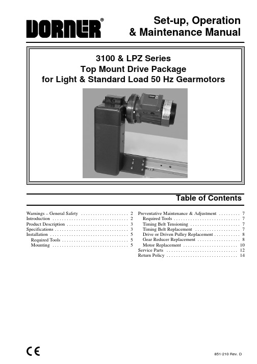
851-210 Rev. DSet-up, Operation& Maintenance ManualTable of ContentsWarnings – General Safety 2. . . . . . . . . . . . . . . . . . . . Introduction 2. . . . . . . . . . . . . . . . . . . . . . . . . . . . . . . . Product Description 3. . . . . . . . . . . . . . . . . . . . . . . . . . Specifications 3. . . . . . . . . . . . . . . . . . . . . . . . . . . . . . . Installation 5. . . . . . . . . . . . . . . . . . . . . . . . . . . . . . . . . Required Tools 5. . . . . . . . . . . . . . . . . . . . . . . . . . . . Mounting 5. . . . . . . . . . . . . . . . . . . . . . . . . . . . . . . .Preventative Maintenance & Adjustment 7. . . . . . . . . Required Tools 7. . . . . . . . . . . . . . . . . . . . . . . . . . . . Timing Belt Tensioning 7. . . . . . . . . . . . . . . . . . . . . Timing Belt Replacement 7. . . . . . . . . . . . . . . . . . . Drive or Driven Pulley Replacement 8. . . . . . . . . . . Gear Reducer Replacement 8. . . . . . . . . . . . . . . . . . Motor Replacement 10. . . . . . . . . . . . . . . . . . . . . . . Service Parts 12. . . . . . . . . . . . . . . . . . . . . . . . . . . . . . Return Policy 14. . . . . . . . . . . . . . . . . . . . . . . . . . . . . .3100 & LPZ Series Top Mount Drive Package for Light & Standard Load 50 Hz Gearmotors SOMM851-210 Rev. D 2Dorner Mfg. Corp.IntroductionIMPORTANT: Some illustrations may showguards removed. Do NOT operate equipment with-out guards.Upon receipt of shipment:D Compare shipment with packing slip. Contact factory regarding discrepancies.D Inspect packages for shipping damage. Contact carrier regarding damage.D Accessories may be shipped loose. See accessory in-structions for installation.Dorner 3100 Series conveyors are covered by patent numbers 5156260, 5156261, 5203447, 5265714 and patent applications in other countries.Dorner LPZ Series conveyors are covered by patent numbers 5156260, 5156261, 5203447, 5265714,5875883 and patent applications in other countries.Dorner ’s Limited Warranty applies.Dorner reserves the right to make changes at any time without notice or obligation.Warnings – General Safety3100 & LPZ Series Top Mount Drive Package for Light & Standard Load 50 Hz Gearmotors SOMMDorner Mfg. Corp.3851-210 Rev. DRefer to Figure 1 for typical components.A ConveyorB Mounting BracketC GearmotorD Timing Belt TensionerE CoverF Timing BeltG Drive Pulley HDriven PulleyTypical ComponentsFigure 1HAECGB DFSpecificationsGearmotor Mounting Package Models:Example:5– = flat belt, A through J = cleated belt Driven Pulley (see Table 2 & 3)* See “Ordering and Specifications ” Catalog for details.Table 1: Gearmotor SpecificationsProduct DescriptionSpecificationsTable 2: Belt Speeds for Fixed Speed 905 50 Hz Gearmotors(vp) = voltage and phase21 = 230 V, 1-phase23 = 230 V, 3-phase43 = 400 V, 3-phaseTable 3: Belt Speeds for Variable Speed 905 50 Hz GearmotorsNOTE: For belt speed other than those listed, con-tact factory for details.3100 & LPZ Series Top Mount Drive Package for Light & Standard Load 50 Hz Gearmotors SOMM851-210 Rev. D4Dorner Mfg. Corp.3100 & LPZ Series Top Mount Drive Package for Light & Standard Load 50 Hz Gearmotors SOMMDorner Mfg. Corp.5851-210 Rev. DRequired ToolsD Hex key wrenches:2 mm, 2.5 mm,3 mm, 5 mm D Straight edge D Torque wrenchMountingInstallation Component ListI Top Mount Assembly J Drive Pulley K CoverL M3 Socket Head Screws (4x)M Driven Pulley N KeyO M5 Socket Head Screws (6x)PTiming Belt1.Typical components (Figure 2)Figure 2MNPIJ KLONOTE: Gearmotor may be operated in positions 1,2 or3 (Figure 3).Figure 33212.If required, change gearmotor position by removingfour (4) screws (Q of Figure 4). Rotate gearmotor to other position and replace screws (Q). Tighten to 12 Nm.Figure 4QQ3.Locate drive output shaft (R of Figure 5) and removescrews (S).Figure 5RSInstallation3100 & LPZ Series Top Mount Drive Package for Light & Standard Load 50 Hz Gearmotors SOMM851-210 Rev. D 6Dorner Mfg. Corp.4.Attach mount assembly (I of Figure 6) with screws(O). Install medium length screws on bottom, long screw upper left, short screws upper right. Tighten screws to 9 Nm.Figure 6OO5.Install key (N of Figure 7).Figure 7NMJP6.Wrap timing belt (P) around driven pulley (M) anddrive pulley (J). Install driven pulley (M) onto conveyor shaft.ing a straight edge (T of Figure 8), align drivenpulley (M) with drive pulley (J). Tighten driven pulley taper lock screws (U, in pulley hub).Figure 8TUM 8.Depending on conveyor belt travel (direction 1 or 2),locate timing belt tensioner (V of Figure 9) as shown.Tension timing belt to obtain 3 mm deflection for 3 kg of force at timing belt mid-point (W). Tighten tensioner screw to 12 Nm.Figure 99.Install cover (K of Figure 10) with four (4) screws(L). Tighten screws to 4 Nm.Figure 10KLLInstallation3100 & LPZ Series Top Mount Drive Package for Light & Standard Load 50 Hz Gearmotors SOMMDorner Mfg. Corp.7851-210 Rev. DRequired ToolsD Hex key wrenches:2 mm, 2.5 mm,3 mm, 5 mmD Adjustable wrench (for hexagon head screws)D Straight edge D Torque wrenchTiming Belt Tensioning1.Remove four (4) screws (L of Figure 10) and removecover (K).2.Loosen tensioner (V of Figure 11).Figure 11V3.Depending on conveyor belt travel (direction 1 or 2),locate timing belt tensioner (V of Figure 9) as shown.Tension timing belt to obtain 3 mm deflection for 3 kilograms of force at timing belt mid-point (W).Tighten tensioner screw to 12 Nm.4.Install cover (K of Figure 10) with four (4) screws(L). Tighten screws to 4 Nm.Timing Belt Replacement1.Remove four (4) screws (L of Figure 10) and removecover (K).2.Loosen tensioner (V of Figure 11).3.Remove timing belt (P of Figure 12).NOTE: If timing belt does not slide over pulleyflange, loosen taper-lock screws in driven pulley hub (U of Figure 12) and remove pulley with belt (P). For re-installation, see steps 6 and 7 on page 6.Figure 12UP4.Install new timing belt.5.Depending on conveyor belt travel (direction 1 or 2),locate timing belt tensioner (V of Figure 9) as shown.Tension timing belt to obtain 3 mm deflection for 3kilograms of force at timing belt mid-point (W).Tighten tensioner screw to 12 Nm.6.Install cover (K of Figure 10) with four (4) screws(L). Tighten screws to 4 Nm.Preventive Maintenance and Adjustment3100 & LPZ Series Top Mount Drive Package for Light & Standard Load 50 Hz Gearmotors SOMM851-210 Rev. D 8Dorner Mfg. Corp.Drive or Driven Pulley Replacementplete steps 1 through 3 of “Timing BeltReplacement ” section on page 7.2.Loosen taper-lock screws and remove drive or drivenpulley.NOTE: If drive pulley (J of Figure 13) is replaced,wrap timing belt around drive pulley and complete step 3.plete steps 6 through 9 of “Installation ” sectionon page 6.Gear Reducer ReplacementNOTE: The gear reducer and output shaft arepermanently fixed with Loctite R Adhesive. Both components must be replaced. See “Service Parts ”Section for part numbers.1.Remove four (4) screws (L of Figure 10) and removecover (K).2.Loosen tensioner (V of Figure 11).3.Loosen drive pulley taper-lock screws (X of Fig-ure 13). Remove drive pulley (J) and timing belt (P).Figure 13XJ P4.Remove four (4) gear reducer mounting screws (Qof Figure 14). Remove gearmotor.Figure 14QPreventive Maintenance and Adjustment3100 & LPZ Series Top Mount Drive Package for Light & Standard Load 50 Hz Gearmotors SOMMDorner Mfg. Corp.9851-210 Rev. D5.Remove four screws (Y of Figure 15). Detach motorwith adapter flange (Z) from gear reducer (AA).Retain motor output shaft key (AB).Figure 15ACADYZAEABAA6.Remove two (2) screws (AC) and detach output shaftcover (AD).7.Remove gear reducer output shaft key (AE).8.Apply Loctite R 680 Adhesive (AI of Figure 16) tonew shaft.Figure 16AI9.Insert the new shaft with adhesive (AG of Figure 17)and key (AH) into new gear reducer. Tighten set screws (AF) to 3 Nm.Figure 17AFAGAHNOTE: Allow Loctite R Adhesive to cure for one (1)hour prior to starting conveyor.IMPORTANT: Be extremely careful when couplingmotor to gear reducer. Avoid misalignment and forcing the connection causing possible permanent gear reducer seal damage.10.With key (AB of Figure 15) in keyway, slide motorwith adapter flange (Z) and gear reducer (AA)together. Install screws (Y) and tighten.11.Install gearmotor to mounting bracket and tightenscrews (Q of Figure 14) to 12 Nm.NOTE: Drive pulley (J of Figure 13) is removed.Wrap timing belt around drive pulley and complete step 12.plete steps 6 through 9 of “Installation ” sectionon page 6.Preventive Maintenance and Adjustment3100 & LPZ Series Top Mount Drive Package for Light & Standard Load 50 Hz Gearmotors SOMM851-210 Rev. D 10Dorner Mfg. Corp.Motor Replacement1.For single phase motor:a .Loosen terminal box screws (AJ of Figure 18) andremove cover (AK).Figure 18AJAKb .(Figure 19). Loosen terminals 2, 6 and ground and remove wires.Figure 19c .Loosen cord grip (AL of Figure 19) and removecord.2.For three phase and VFD variable speed motor:a .Loosen terminal box screws (AJ of Figure 18) andremove cover (AK).b .Record wire colors on terminals U1, V1, W1 & PE (Figure 20). Loosen terminals U1, V1, W1 & PEand remove wires.Figure 20c .Loosen cord grip (AL of Figure 20) and removecord.Preventive Maintenance and Adjustment3100 & LPZ Series Top Mount Drive Package for Light & Standard Load 50 Hz Gearmotors SOMMDorner Mfg. Corp.11851-210 Rev. D3.Remove four (4) screws (Y of Figure 21). Detachmotor (Z) with adapter flange from gear reducer (AA). Retain motor output shaft key (AB).Figure 21AAZYAB4.Remove four (4) screws and nuts (AM of Figure 22).Remove adapter flange (AN).Figure 22ANAM 5.Install adapter flange (AN) on new motor. Installscrews and nuts (AM) and tighten.IMPORTANT: Be extremely careful when couplingmotor to gear reducer. Avoid misalignment and forcing the connection causing possible permanent gear reducer seal damage.6.With key (AB of Figure 23) in keyway, slide motorwith adapter flange (Z) and gear reducer together.Install screws (Y) and tighten.Figure 23ZABY7.Replace wiring:D For a single phase motor, reverse step 1 on page 10.D For a three phase or VFD variable speed motor, re-verse step 2 on page 10.Preventive Maintenance and Adjustment3100 & LPZ Series Top Mount Drive Package for Light & Standard Load 50 Hz Gearmotors SOMM851-210 Rev. D 12Dorner Mfg. Corp.NOTE: For replacement parts other than thoseshown on this page, contact an authorized Dorner Service Center or the factory.Figure 2412345689121010Service PartsNotes 3100 & LPZ Series Top Mount Drive Package for Light & Standard Load 50 Hz Gearmotors SOMMDorner Mfg. Corp.13851-210 Rev. DNo returns will be accepted without prior written factory authorization. When calling for authorization, please have the following information ready for the Dorner Factory representative or your local distributor: and address of customer.2.Item(s) being returned.3.Reason for return.4.Customer ’s original order number used when ordering the item(s).5.Dorner or distributor invoice number.A representative will discuss action to be taken on the Returned items and provide a Returned Goods Authorization Number to reference.There will be a 15% restocking charge on all new items returned for credit where Dorner was not at fault. These will not be accepted after 60 days from original invoice date. The restocking charge covers inspection, cleaning,disassembly, and reissuing to inventory.If a replacement is needed prior to evaluation of returned item, a purchase order must be issued. Credit (if any) is issued only after return and evaluation is complete.Dorner has representatives throughout the world. Feel free to contact Dorner for the name of your local representative. Our technical sales and service staff will gladly help with your questions on Dorner products.For a copy of Dorner ’s Limited Warranty, contact factory, distributor, service center or visit our website at 851-210 Rev. DPrinted in U.S.A.300Return Policy。
IZM低电压断路器释放设备说明书
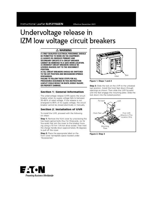
Undervoltage release inIZM low voltage circuit breakersm WARNING(1)ONLY QUALIFIED ELECTRICAL PERSONNEL SHOULDBE PERMITTED TO WORK ON THE EQUIPMENT.(2)ALWAYS DE-ENERGIZE PRIMARY ANDSECONDARY CIRCUITS IF A CIRCUIT BREAKERCANNOT BE REMOVED TO A SAFE WORK LOCATION.(3)DRAWOUT CIRCUIT BREAKERS SHOULD BELEVERED(RACKED)OUT TO THE DISCONNECTPOSITION.(4)ALL CIRCUIT BREAKERS SHOULD BE SWITCHEDTO THE OFF POSITION AND MECHANISM SPRINGSDISCHARGED.FAILURE TO FOLLOW THESE STEPS FOR ALL PROCEDURES DESCRIBED IN THIS INSTRUCTION LEAFLET COULD RESULT IN DEATH,BODILY INJURY, OR PROPERTY DAMAGE.Section1:General information The undervoltage release(UVR)opens the circuit breaker when its supply voltage falls to between 35–60%of rated voltage.If the release is not energized to85%of its supply voltage,the circuit breaker cannot be closed electrically or manually. Section2:Installation of UVRTo install the UVR,proceed with the followingsix steps:Step1:Remove the front cover by unscrewing the hex-head captive bolts(four for three-pole,six for four-pole)that join the cover to the breaker hous-ing using a10mm1/4-inch drive socket.Then hold the charge handle down approximately45degrees to pull off the cover.Step2:Place the appropriate label on thefront cover nameplate space located under “Accessories.”Figure1.Steps1and2Step3:Slide the lock on the UVR to the unlocked (up)position.Install the hook feet down through openings as shown.Then slide the UVR forward until the feet engage the mounting plate.Slide the lock down into the locked position.Figure2.Step3Undervoltage release inIZM low voltage circuit breakersEaton Industries GmbH Hein-Moeller-Straße 7-11,53115Bonn,Germany ©2021Eaton Industries GmbH All Rights Reserved Printed in GermanyPublication No.IL0131166EN Effective December 2021Instructional Leaflet IL0131166ENEffective December 2021Eaton is a registered trademark.All other trademarks are property of their respective owners.Step 4:Connect wires from the UVR to secondary contact positions 93and 94,in keeping with markings on wires.Disclaimer of warranties and limitation of liabilityThe information,recommendations,descriptions,and safety notations in this document are based on Eaton Corporation’s (“Eaton”)experience and judgment,and may not cover allcontingencies.If further information is required,an Eaton sales office should be consulted.Sale of the product shown in this literature is subject to the terms and conditions outlined in appropriate Eaton selling policies or other contractual agreement between Eaton and the purchaser.THERE ARE NO UNDERSTANDINGS,AGREEMENTS,WARRANTIES,EXPRESSED OR IMPLIED,INCLUDINGWARRANTIES OF FITNESS FOR A PARTICULAR PURPOSE OR MERCHANTABILITY ,OTHER THAN THOSE SPECIFICALL Y SET OUT IN ANY EXISTING CONTRACT BETWEEN THE PARTIES.ANY SUCH CONTRACT STATES THE ENTIRE OBLIGATION OF EATON.THE CONTENTS OF THIS DOCUMENT SHALL NOT BECOME PART OF OR MODIFY ANY CONTRACT BETWEEN THE PARTIES.In no event will Eaton be responsible to the purchaser or user in contract,in tort (including negligence),strict liability,or otherwise for any special,indirect,incidental,or consequential damage or loss whatsoever,including but not limited to damage or loss of use of equipment,plant or power system,cost of capital,loss of power,additional expenses in the use of existing power facilities,or claims against the purchaser or user by its customers resulting from the use of the information,recommendations,and descriptions contained herein.The information contained in this manual is subject to change without notice.。
- 1、下载文档前请自行甄别文档内容的完整性,平台不提供额外的编辑、内容补充、找答案等附加服务。
- 2、"仅部分预览"的文档,不可在线预览部分如存在完整性等问题,可反馈申请退款(可完整预览的文档不适用该条件!)。
- 3、如文档侵犯您的权益,请联系客服反馈,我们会尽快为您处理(人工客服工作时间:9:00-18:30)。
一、概况:RMZ型煤气增压风机是根据二段式煤气炉的发展趋势,结合单段式煤气发生炉而开发的新型煤气排送机,它从根本上解决了长期以来依赖进口风机或用罗茨鼓风机噪音高流量不能调节的状况。
从投放市场以来的运行证明:该机噪音低、性能曲线平坦、流量调节区域大、效率高、耗能低,特别是密封性好,运行稳定,深受广大顾客的好评。
该机可制成顺时针或逆时针方向旋转,出口角度分别为0度、90度、180度三个方向,用户可根据实际管网分布需要自行选择。
二、用途:本机专门适用于厂矿煤气站煤气增压,高炉、焦炉、转炉煤气增压,氨气、沼气、甲烷等气密性严谨的气体输送,以及高压强制鼓风。
三、型号编制说明以RMZ60-700为例RMZ——热煤气增压60——风机流量(m³/min)700——风机全压(mmH2O) [500℃标准状态下(0.455kg/m3)空气所测的全压] 四、结构特征:该风机为板焊式整体结构,主要有以下部件组成:1、叶轮。
叶轮是整台风机的心脏,因此该机的叶型按新的高效风机理论进行优化设计,材料根据不同需要分别选用优质不锈钢或合金制造,具有较好的抗腐能力和足够的强度。
叶轮成型后,经静、动平衡校正,精度为G4级(高于国标G6.3级)。
2、机壳。
用优质碳素钢与机座整体焊接而成,保证了整机的刚性,机壳内涂环氧树指,以增强抗腐性能;机壳上部设G2″蒸汽管接口,下部设G1″排污阀;风机的进出口法兰采用标准法兰,以利用户管道联接。
3、密封组。
本密封主要采用软填料密封和离心密封,密封内无易损件,结构十分简单,效果特别可靠,更换方便。
4、电机。
本机配套的电机采用YB系列电机,YB系列电机防爆等级为dⅡBT4,防护等级为IP55。
五、安装:1、安装前应详细检查各部件是否因包装运输不妥而导致损坏,如发现损坏,应修整后才能进行安装。
2、检查各部分联接有无松动,若有应即时紧固之。
3、基础做成后,将风机和电动机装上,并检查各部分水平以及风机与电动机轴线是否一致,将蜗壳与转子各部分之间间隙校正好,然后再灌水泥浆。
4、水泥干燥后,再检查各部分之水平、轴线及间隙,然后紧固地基螺栓。
5、安装风机之进出口管道,严格防止管道等部件的重量承受在风机上,从而影响风机的安装质量要求,必要时管道应加装支撑。
6、清理蜗壳及管道和轴承座等内部。
7、安装各传动部分安全防护设施。
8、各项机件附件电器设备仪表等检查完毕应首先空转电动机,检查电动机转向是否符合鼓风机的要求,以防鼓风机反向传动机件松脱。
9、仪表应装在便于管理而且明显的地位,电气应装有信号装置,防止突然事故停电而使鼓风机损坏。
10、进出口管道应严格保证严密不漏气。
六、使用:1、使用单位应当设法将通入风机中的煤气预先净化,否则将会起化学作用,产生腐蚀或煤焦油过多影响正常运转,甚至造成破坏事故。
2、转子的平衡性除了动平衡试验外还取决于本身放置是否平稳,基础是否牢固,电动机运转是否平衡以及转子是否存在不均匀的磨损。
3、机器安装结束(或长时间停车),应先用空气进行试运转以证实它完全正常再输送煤气。
4、运转前的准备工作。
(1)检查机器各部分是否紧固和清洁。
(2)检查进出口调节阀是否灵活,各种仪表开关是否正常,安全防护设施是否装妥。
(3)进行空气试车时应保证煤气管道密闭,只允许将风机部分通向大气层。
(4)将风机进出口阀门做如下调整:进口阀门紧闭,出口阀门稍开。
(5)按风机所用电动机的名牌规格接通电源。
(6)检查风机各部分润滑油是否充足。
5、启动:(1)按照电动机操作守则开动风机。
(2)渐渐地打开出口阀门和进口阀门到需要程度时注意电动机是否过载,如电动机过载应控制进出口风量,不使超过规定。
(3)仔细倾听风机内部是否有不正常的磨擦声。
(4)仔细注意机器有无振动或不正常的噪音,如有振动或不正常的噪音应立即停车检查原因。
(5)检查轴承温升是否正常,一般不超过室内温度35度~40度,轴承表温最高不大于65度。
(6)检查进出口管道严密性和各种仪表使用是否正常。
6、正常使用应注意:(1)基础和机器有无振动(一般在基础牢固情况下轴承振动不应大于0.05毫米)。
(2)应保证煤气焦油及杂质在未进入风机前加以严格净化,以防焦油附着于转子上从而破坏平衡。
(3)风机进口应保持正压操作,以防进气管道有大气层空气吸入产生事故。
(4)不允许煤气在风机回流或使煤气产生意外的碰撞。
(5)如供气量嫌多,应调节进出口阀门以保证进口保持正压。
(6)保证风机不应有不正常发热现象。
(7)应保持机器的整洁以及油箱和滤清器的清洁。
(8)定时记录各项运转情况资料。
7、停车:(1)通入蒸汽冲洗焦油。
(2)清理机器内部焦油及杂质。
(3)调节各项仪表及进出口阀门达到准备运转的要求。
8、一般故障及其原因:(1)风量不足,管道系统阻力超过鼓风机规定风压。
(2)风压不足:A管道系统阻力估计过高,必要时应以调节阀门不使过低;B煤气比重小于额定数据。
(3)电动机超负荷:A风压过低致使送风量过大;B 煤气比重大于额定数据。
(4)振动:A主轴变形;B基础不牢固;C出口阀门控制过小产生飞动;D机器内部有碰擦现象;E电动机与鼓风机轴心线不一致。
(5)轴承温升过高:A润滑油有杂质;B转子失去平衡;C鼓风机与联轴器轴心线不一致;D毡圈过紧使轴发热;E润滑脂加注过多。
9、附注:当输送煤气时由于各使用单位煤气特性不同,当地使用条件不同,因此各使用单位应根据本说明书精神对操作守则做必要的调整和增添。
七、维护检修:1、制订定期检修制度,规定在新机器使用100小时后将润滑油重新换掉,以后每隔半年小修一次,每年大修检查一次。
2、检修时电源开关上应做好显著标志,停止使用。
3、拆修前需冲入蒸汽洗涤并将机器内剩余煤气去除干净。
4、检修时应用煤油清洗各部件进行检查。
5、检修完毕进行装配可参照安装说明所述各项要求进行检查。
6、凡备用风机平时不使用时应定期将转子旋转120度或80度,以防主轴弯曲变形。
八、订货须知:1、样本中的压力是500℃标准状态下(0.455kg/m3)空气所测的全压,请根据所输送煤气的比重,温度进行性能换算。
2、风机的型号、旋转方向、出风口角度可根据需要在订货时注明。
3、其他特殊要求,需另订技术协议后方可签定定货合同。
4、随着技术的进步和有关标准的修改,样本中的尺寸和技术参数有所变动时,恕不另行通知,请广大用户谅解。
九、性能与选用件表:型号传动方式转速(rpm)序号流量(m3/h)全压(pa)电动机型号功率(kw)RMZ30-170 D 2900 1 1174 1749YB112M-2 42 1394 17803 1616 17754 1839 17405 2062 16906 2281 16337 2504 1563RMZ30-470 D 2900 1 768 4359YB132S2-2 7.52 1075 45683 1383 47014 1690 47395 1997 4698YB160M1-2 116 2304 45837 2612 4406RMZ50-200 D 2900 1 1610 2165YB112M-2 42 1932 21923 2254 21814 2576 21435 2844 2096YB132S1-2 5.56 3166 20237 3488 1930RMZ50-600 D 2950 1 1110 5649YB160M2-2 152 1554 59203 1998 60934 2442 61425 2887 6089YB180M-2 226 3331 59407 3775 5710型号传动转速(rpm)序号流量(m3/h)全压(pa)电动机型号功率(kw)RMZ60-270 D 2900 1 2262 2729YB132S2-2 7.52 2714 27643 3167 27504 3619 27015 3996 2643YB160M1-2 116 4448 25497 4901 2432RMZ 60-700 D 2950 1 1341 6465YB180M-2 222 1877 67753 2414 69724 2950 70285 3487 6968YB200L1-2 306 4023 67977 4560 6534RMZ70-530 D 2950 1 2580 5600YB200L1-2 302 3355 55353 3988 53874 4077 52575 5410 51996 5870 49337 6243 4920RMZ70-770 D 2950 1 1591 7248YB200L1-2 302 2228 75953 2865 78164 3502 78805 4138 7812YB200L2-2 376 4775 76217 5412 7326RMZ100-200 D 2900 1 4293 2293YB160M1-2 112 4706 22743 5114 22304 5527 21765 5941 21106 6349 20457 6762 1968型号传动转速(rpm)序号流量(m3/h)全压(pa)电动机型号功率(kw)RMZ100-350 D 2900 1 3220 3477YB160M2-2 152 3865 35213 4509 35034 5153 34415 5690 3366YB180M-2 226 6334 32467 6978 3096RMZ100-630 D 2950 1 2996 6162YB200L2-2 372 3824 62813 4651 64344 5478 64965 6306 6434YB225M-2 456 7133 63577 7960 6162RMZ110-830 D 2950 1 3592 8288YB225M-2 452 4653 86083 5369 86444 6328 82285 6942 7971YB250M-2 556 7499 78147 9202 7468RMZ130-270 D 2900 1 6032 2721YB180M-2 222 6612 28673 7185 28124 7766 27435 8346 26606 8919 25777 9500 2478RMZ130-450 D 2900 1 4610 4452YB200L1-2 302 5532 45103 6454 44874 7376 44065 8144 4309YB200L2-2 376 9066 41557 9988 3962型号传动转速(rpm)序号流量(m3/h)全压(pa)电动机型号功率(kw)RMZ130-530 D 2950 1 5538 5697YB225M-2 452 6471 56253 7233 54524 7930 52265 8716 49786 8451 47677 10140 4466RMZ130-630 D 2950 1 4295 6081YB225M-2 452 5481 61823 6667 63484 7853 64115 9039 6348YB250M-2 55 6 10225 6273RMZ130-770 D 2950 1 3832 7663YB225M-2 452 4648 77463 5237 78194 6376 78245 7586 7617YB250M-2 556 8835 75487 9159 7476RMZ 180-350 D 2950 1 8588 3685YB200L2-2372 9415 36543 10230 35834 11056 34945 11883 33886 12699 3282YB225M-2 45 7 13552 3158RMZ200-550 D 2950 1 6592 5703YB250M-2 552 7988 57863 9232 57554 10547 56545 11654 5530YB280S-2 756 12950 53307 14304 5076型号传动方式转速(rpm)序号流量(m3/h)全压(pa)电动机型号功率(kw)RMZ280-1000 D 2950 1 16235 7977YB280M-2 902 17036 76803 17978 73454 18562 7104RMZ200-870 D 2950 1 4813 9003YB280S-2 752 6751 88183 9022 89264 10943 8859YB280M-2 905 12644 85376 14397 8070YB315S-2 110 7 15664 7631RMZ200-950 D 2950 1 6850 9253YB315S-2 1102 9240 93483 11200 95004 12560 95845 14350 9462YB315M-2 1326 15480 93107 17380 9196RMZ 220-500 D 2950 1 9495 5578YB250M-2 552 10680 55023 12705 52824 12869 50315 13955 47206 14996 44227 16318 4134RMZ260-450 D 2950 1 12292 4722YB250M-2 552 13475 46823 14643 45904 15826 4475YB280S-2 755 17009 43386 18177 42017 19360 4041RMZ280-450 D 2950 1 12200 4720YB250M-2 552 13475 46823 14640 45904 15826 44735 17000 4336YB280S-2 756 18180 42017 19360 4041型号传动方式转速(rpm)序号流量(m3/h)全压(pa)电动机型号功率(kw)RMZ280-630 D 2950 1 9210 6289YB280S-2 752 11260 63693 13240 63354 15420 62245 17180 6167YB280M-2 906 18460 59937 20350 5894RMZ300-970 D 2950 1 10950 9443YB315M-2 1322 13450 96903 14700 97744 15950 9789YB315L1-2 1605 18460 98046 20960 96637 22200 9485RMZ400-570 D 2950 1 17580 6061YB315S-2 1102 19280 60123 20950 58904 22640 57425 24330 5563YB315M-2 1326 26000 53887 27700 5179RMZ400-700 D 2950 1 18600 7402YB315M-2 1322 20300 73343 21940 71974 23780 70225 25680 6810YB315L1-2 1606 27500 65977 29800 6354RMZ500-700 D 2950 1 23400 7353YB315L1-2 1602 25660 72733 27880 71294 30130 69505 32390 6734YB315L2-2 2006 34600 65177 35200 6384。
