日版KC-E50中文说明书参考
汽车维修工具说明书

AUTOMOTIVE TOOLSGrease, Engine, Pick up tool, Refrigeration Tool, Tyre Repare, Bodywork Maintain Tool汽保机修专用工具润滑工具、引擎维修、底盘/传动维修、制冷维修工具、轮胎维护、车身维修、通用工具工具包, 箱, 车 TOOLS BAG & STORAGE工具包套装、工具包、塑料工具箱、铁工具箱、工具车、铝合金工具箱Tool bag Set, Tool Bag, Tool Box, Tool Trolley, Aluminium Tool BoxHOIST TOOLS立式千斤顶、卧式千斤顶Hydraulic Bottle Jacks, Garage Jack起重类工具液压类工具 HYDRAULIC TOOLS液压压线钳、液压断线钳、液压拉马Hydraulic Crimping Tool, Hydraulic Cutting Tool, Hydraulic PullerTool Set, Flashlight, Tweezer, Voltage Tester, Pliers, Crimping Tool, Screwdriver, Electric IronELECTRICAL TOOLS电子电工类工具套装类、手电筒、万用表、测电类、镊子、电工电子钳、电缆剪、电工剪刀、精密螺丝批、电烙铁及附件DRILLING TOOLS 丝锥板牙及组套、绞手、直柄麻花钻及套装HSS Ground Thread Tap, Stocks, Cobalt Stub Drills刃具类工具PIPE TOOLS切管类、弯管器、管钳Tubing Cutter, Pipe Bender, Pipe Wrench管道类工具AIR TOOLS气动扳手、气动套筒及配件Impact Wrench, Impact Socket and Accessories气动工具FINISHING TOOLS金刚石锉、 修边器、 钳工锉Diamond Needle File, Deburring Tool, File表面修整类工具油嘴特殊设计,增加钢珠自锁,确保油不回流。
AI一TEK505说明书

AI一TEK505说明书AI一TEK505 使用说明书亲爱的顾客:;非常感谢您对TEK的支持。
为了您能更方便安全的使用并充分发挥该引擎的最大性能。
请在使用前仔细阅读使用说明书。
并妥善保管此书以备日后查阅,参考。
我们将持续创新开发,提高制造精度。
请相信TEK会不断努力,带给您最先进的引擎。
TEK引擎带您的优质服务:1.优化设计,高精度制造。
并经过全方位测试。
2.每一台发动机出厂前都经过详细调整,低速稳定,高速暴力,更方便您的使用。
3. 24个月的条件固保4.您有任何建议或投诉可直接联系生产商,我们会尽最大努力为您排优解难。
我们的邮箱地址:有限的保瞪书:我价授予徙媾置日期起24个月保瞪。
_张保罩野有瑕疵的材料或袈造缺陷部分更换。
但因使用及操作不嵩,使用非原戚零件及不熟辣的修理舍被取消保固。
喆您在瞒置之畤要求您的不鲔商填好一张保澄书。
重要:保留煊份瞪明在安全的地方因悫遗失暄张保澄书+没有收掾不舍被承。
安全注意事项:模型并非玩具,该引擎动力强大,请远离人群,避免在恶劣天气条件下飞行。
飞机质量问题,电子设备故障,电池电量不足以及操作上的失误都有可能发生不可预期的意外。
用户必须首先了解引擎的使用,限制,并知道因自身疏忽造成的任何以外责任。
我们强烈建议您在使用前详细阅读此书,切勿轻率安装与操作。
注意!任何制造商与经销商都无法对用户于零件使用的损耗异常或组装不当以及操作不当所发生之意外付任何责任,本产品是提供给有操作模型汽油发动机经验的成人或者有相当技术的人员在旁指导于当地合法的遥控场地飞行,以确保安全无误下操作使用,产品售出后本公司将不负任何操作和使用控制上的任何性能安全责任。
使用该引擎需要准备的工具为了您的安全和维护您的保单请按说明步骤使用引擎:一:引擎的安装1.引擎支架应安装在一平面上,确定连接螺丝没有受到外力挤压。
使用合适的力量锁紧支架螺丝。
重要:在化油器周遏楼髓的内部必须圄上防油漆或是环氧榭脂.防止汽油徙化油器喷出来伤害形楼内部。
RCS-9000系列远动通讯装置技术和使用说明书(ZL_TXZ

1.6 组态软件简介 ................................................30
2. RCS-9698C/D 远动通信装置................................................................................ 31
1.5 总控 VQC 说明 ................................................18 1.5.1 VQC 的应用 ..................................................... 18 1.5.2 VQC 的功能 ..................................................... 18 1.5.3 VQC 的原理 ..................................................... 18 1.5.4 VQC 的使用 ..................................................... 24
Wheelock Series E50 音箱说明书
273 Branchport Avenue Thank you for using our products.Long Branch, N.J. 07740(800) 631-2148 INSTALLATION INSTRUCTIONS SERIES E50 SPEAKERSUse this product according to this instruction manual. Please keep this instruction manual for future reference. GENERAL:Wheelock’s Series E50 Speakers are UL Listed under UL Standard 1480 for Speaker Appliances. They are designed for multiple power requirements with high dBA output at each power tap. All models offer a choice of field selectable taps, 1/8W to 2W, for either 25.0VRMS or 70.0VRMS audio systems. The design incorporates a high efficiency speaker for maximum output at minimum power across a frequency range of 400Hz to 4000Hz, and features a sealed back construction for extra protection and improved audibility. All models are UL Listed for indoor use only with the backboxes specified in these instructions (see Mounting Options).NOTE: All CAUTIONS and WARNINGSThe speaker appliance is a fire alarm device – do not paint.FOLLOWING INSTRUCTIONS, CAUTIONS AND WARNINGS COULD RESULT IN IMPROPER APPLICATION, INSTALLATION AND/OR OPERATION OF THESE PRODUCTS IN AN EMERGENCY SITUATION, WHICH COULD RESULT IN PROPERTY DAMAGE AND SERIOUS INJURY OR DEATH TO YOU AND/OR OTHERS. SPECIFICATIONS:Table 1: UL Listed Models and RatingsSpeakerModel Voltage(VRMS) dBA at 10 Feet(Rated Watts)MountingOptions1/81/41/212E50 25/70 77.0 79.5 82.5 85.0 88.0 A,BNOTES:1.All models are UL Listed for indoor use with a temperature range of +32ºF to +120ºF (0ºC to +49ºC) and maximumhumidity of 85% RH.2.dBA is rated per UL Standard 1480 for Speaker Appliances. Frequency range of speakers is 400 – 400HZCopyright 2004 Wheelock, Inc. All rights reservedWIRING INFORMATION:A 1.5µF blocking capacitor for DC supervision of audio lines by the FACP is factory wired in series with the speaker input. Supervision voltage must not exceed 33 volts DC.Figure 1: Figure 2:COM+FROM PRECEDING SPEAKER TO NEXT SPEAKER *1. Series E50 Speaker models have in-out wiringterminals that accept two #12 to #18 AmericanWire Gauge (AWG) wires at each screw terminal. Strip leads 3/8 inches and connect toscrew terminals.2. Break all in-out wire runs on supervisedcircuits to assure integrity of circuit supervision as shown in Figure 2. The polarityshown in the wiring diagrams is for operationof the appliances.GROUNDING: Connect ground wire to backbox. Install signaling appliance to backbox using mounting screws provided.NOTE: Check electrical ratings specified in tables 1 and 2 (as appropriate) to ensure proper electrical input. Be sure that speaker wiring is connected to speaker terminals only and strobe wiring is connected to strobe terminals only. Check to insure that wiring at FACP is correct.MALFUNCTION.Figure 3: Jumper plug is used to select dBA loudness.Figure 4: Tap Settings (Factory setting is 70V @ 1/2W (F))NOTE: Use needle nose pliers to pull and properly insert the jumper plug to the desired tap setting.Connect speaker wires to common and positive of terminal block and select the power tap terminal for 1/8W, 1/4W, 1/2W, 1W or 2W; 25V or 70V as required (see Figures 1, 2, 3, 4 and Table 2). Each doubling of rated Watts increases sound output by 3 dBA. Each letter corresponds to a plug position of the header located on the printed circuit board. Select voltage and wattage as shown in Table 2 below.Table 2: Speaker Voltage and Wattage Connection ChartPosition 25V 70VA 2 ------B 1 ------C 1/2 ------D 1/4 2E 1/8 1F ------ 1/2G ------ 1/4H ------ 1/8NOTE: The speaker strobe appliances must be set to the desired dBA sound output level before they are installed. This is done by properly inserting jumper plugs in accordance with these instructions.Always operate audio amplifiers and speakers within their specified ratings. Excessive input may distort sound quality and may damage audio equipment. Improper input voltage can damage speaker. If distortion is heard, check for clipping of the audio appliance with an oscilloscope and reduce the amplifier input level or gain level to eliminate any clipping.MOUNTING OPTIONS:The following figures show the maximum number of field wires (conductors) that can enter the backbox used with each mounting option. If these limits are exceeded, there may be insufficient space in the backbox to accommodate the field wires and stresses from the wires could damage the product.Although the limits shown for each mounting option comply with the National Electrical Code (NEC), Wheelock recommends use of the largest backbox option shown and the use of approved stranded field wires, whenever possible, to provide additional wiring room for easy installation and minimum stress on the product from wiring.NOTE: Surface backbox (SSB) in Figure B, is compatible with wiremold and conduit. Mounting holes are for single-gang, double-gang, and #10 wood screws for stud mounting. If metal conduit is installed onto top and bottom conduit entrances, then an insulated grounding wire (18 AWG, supplied) must be connected between the top and bottom plate by using thread cutting screws (supplied) to provide electrical continuity per UL 50. See Figure 5.Figure 5:MOUNTING PROCEDURES:Check that the installed product will have sufficient clearance and wiring room prior to installing backboxes and conduit, especially if sheathed multiconductor cable or 3/4" conduit fittings are used.1. E50 models have an integrated Speaker Mounting Plate.2. The Speaker Mounting Plate must be oriented correctly when it is mounted to the backbox. Refer to mounting options fororientation.3. First mount the Speaker Mounting Plate to the backbox. Next slide the grille over the Speaker Mounting Plate until both snapsare engaged.4. When terminating field wires, do not use more lead length than required. Excess lead length could result in insufficient wiringspace for the signaling appliance.5. Conduit entrances to the backbox should be selected to provide sufficient wiring clearance for the installed product.6. Do not pass additional wires (used for other than the signaling appliance) through the backbox. Such additional wires couldresult in insufficient wiring space for the signaling appliance.7. Mounting hardware for each mounting option is supplied. Use (2) wood screws to mount surface backbox on wall surface.8. All models can be flush mounted to a 4” square by 2-1/8” deep backbox in the wall (Figure A).9. Use care and proper techniques to position the field wires in the backbox so that they use minimum space and produce minimumstress on the product. This is especially important for stiff, heavy gauge wires and wires with thick insulation or sheathing.10 Use care to prevent speaker cone damage when driving screws for speaker product mounting.If this appliance is required to produce a distinctive three-pulse Temporal Pattern Fire Alarm Evacuation Signal (for total evacuation) in accordance with NFPA 72, the appliance must be used with a fire alarm control unit that can generate the temporal pattern signal. Refer to manufacturer’s installation manual for details.NOTE: NFPA 72/ANSI 117.1 conforms to ADAAG Equivalent Facilitation Guidelines in using fewer, higher intensity strobes within the same protected area.Check the installation instructions of the manufacturers of other equipment used in the system for any guidelines or restrictions on wiring and/or locating Notification Appliance Circuits (NAC) and notification appliances. Some system communication circuits and/or audio circuits, for example, may require special precautions to assure electrical noise immunity (e.g. audio crosstalk).NOTE: This equipment has been tested and found to comply with the limits for a Class B digital device, pursuant to Part 15 of the FCC Rules. These limits are designed to provide reasonable protection against harmful interference in residential installation. This equipment generates, uses and can radiate radio frequency energy and, if not installed and used in accordance with the instructions, may cause harmful interference to radio communications. However, there is no guarantee that interference will not occur in a particular installation. If this equipment does cause harmful interference to radio or television reception, which can be determined by turning the equipment off and on, the user is encouraged to try to correct the interference by one or more of the following measures: 1) Reorient or relocate the receiving antenna, 2) Increase the separation between the equipment and receiver, 3) Connect the equipment into an outlet on a circuit different from that to which the receiver is connected, and 4) Consult the dealer or an experienced radio/TV technician for help.ANY MATERIAL EXTRAPOLATED FROM THIS DOCUMENT OR FROM WHEELOCK MANUALS OR OTHER DOCUMENTS DESCRIBING THE PRODUCT FOR USE IN PROMOTIONAL OR ADVERTISING CLAIMS, OR FOR ANY OTHER USE, INCLUDING DESCRIPTION OF THE PRODUCT'S APPLICATION, OPERATION, INSTALLATION AND TESTING IS USED AT THE SOLE RISK OF THE USER AND WHEELOCK WILL NOT HAVE ANY LIABILITY FOR SUCH USE.IMPORTANT: READ SEPARATE "GENERAL INFORMATION" SHEET FOR INFORMATION ON THE PLACEMENT, LIMITATIONS, INSTALLATION, FINAL CHECKOUT, AND PERIODIC TESTING OF NOTIFICATION APPLIANCES.Limited WarrantyWheelock products must be used within their published specifications and must be PROPERLY specified, applied, installed, operated, maintained and operationally tested in accordance with these instructions at the time of installation and at least twice a year or more often and in accordance with local, state and federal codes, regulations and laws. Specification, application, installation, operation, maintenance and testing must be performed by qualified personnel for proper operation in accordance with all of the latest National Fire Protection Association (NFPA), Underwriters' Laboratories (UL), Underwriters’ Laboratories of Canada (ULC), National Electrical Code (NEC), Occupational Safety and Health Administration (OSHA), local, state, county, province, district, federal and other applicable building and fire standards, guidelines, regulations, laws and codes including, but not limited to, all appendices and amendments and the requirements of the local authority having jurisdiction (AHJ). Wheelock products when properly specified, applied, installed, operated, maintained and operationally tested as provided above are warranted against mechanical and electrical defects for a period of three years from date of manufacture (as determined by date code). Correction of defects by repair or replacement shall be at Wheelock's sole discretion and shall constitute fulfillment of all obligations under this warranty. THE FOREGOING LIMITED WARRANTY SHALL IMMEDIATELY TERMINATE IN THE EVENT ANY PART NOT FURNISHED BY WHEELOCK IS INSTALLED IN THE PRODUCT. THE FOREGOING LIMITED WARRANTY SPECIFICALLY EXCLUDES ANY SOFTWARE REQUIRED FOR THE OPERATION OF OR INCLUDED IN A PRODUCT. WHEELOCK MAKES NO REPRESENTATION OR WARRANTY OF ANY OTHER KIND, EXPRESS, IMPLIED OR STATUTORY WHETHER AS TO MERCHANTABILITY, FITNESS FOR A PARTICULAR PURPOSE OR ANY OTHER MATTER.USERS ARE SOLELY RESPONSIBLE FOR DETERMINING WHETHER A PRODUCT IS SUITABLE FOR THE USER'S PURPOSES, OR WHETHER IT WILL ACHIEVE THE USER'S INTENDED RESULTS. THERE IS NO WARRANTY AGAINST DAMAGE RESULTING FROM MISAPPLICATION, IMPROPER SPECIFICATION, ABUSE, ACCIDENT OR OTHER OPERATING CONDITIONS BEYOND WHEELOCK'S CONTROL.SOME WHEELOCK PRODUCTS CONTAIN SOFTWARE. WITH RESPECT TO THOSE PRODUCTS, WHEELOCK DOES NOT WARRANTY THAT THE OPERATION OF THE SOFTWARE WILL BE UNINTERRUPTED OR ERROR-FREE OR THAT THE SOFTWARE WILL MEET ANY OTHER STANDARD OF PERFORMANCE, OR THAT THE FUNCTIONS OR PERFORMANCE OF THE SOFTWARE WILL MEET THE USER'S REQUIREMENTS. WHEELOCK SHALL NOT BE LIABLE FOR ANY DELAYS, BREAKDOWNS, INTERRUPTIONS, LOSS, DESTRUCTION, ALTERATION, OR OTHER PROBLEMS IN THE USE OF A PRODUCT ARISING OUT OF OR CAUSED BY THE SOFTWARE.THE LIABILITY OF WHEELOCK ARISING OUT OF THE SUPPLYING OF A PRODUCT, OR ITS USE, WHETHER ON WARRANTIES, NEGLIGENCE, OR OTHERWISE, SHALL NOT IN ANY CASE EXCEED THE COST OF CORRECTING DEFECTS AS STATED IN THE LIMITED WARRANTY AND UPON EXPIRATION OF THE WARRANTY PERIOD ALL SUCH LIABILITY SHALL TERMINATE. WHEELOCK IS NOT LIABLE FOR LABOR COSTS INCURRED IN REMOVAL, REINSTALLATION OR REPAIR OF THE PRODUCT BY ANYONE OTHER THAN WHEELOCK OR FOR DAMAGE OF ANY TYPE WHATSOEVER, INCLUDING BUT NOT LIMITED TO, LOSS OF PROFIT OR INCIDENTAL OR CONSEQUENTIAL DAMAGES. THE FOREGOING SHALL CONSTITUTE THE SOLE REMEDY OF THE PURCHASER AND THE EXCLUSIVE LIABILITY OF WHEELOCK.IN NO CASE WILL WHEELOCK'S LIABILITY EXCEED THE PURCHASE PRICE PAID FOR A PRODUCT.Limitation of LiabilityWHEELOCK'S LIABILITY ON ANY CLAIM OF ANY KIND, INCLUDING NEGLIGENCE AND BREACH OF WARRANTY, FOR ANY LOSS OR DAMAGE RESULTING FROM, ARISING OUT OF, OR CONNECTED WITH THIS CONTRACT, OR FROM THE MANUFACTURE, SALE, DELIVERY, RESALE, REPAIR OR USE OF ANY PRODUCT COVERED BY THIS ORDER SHALL BE LIMITED TO THE PRICE APPLICABLE TO THE PRODUCT OR PART THEREOF WHICH GIVES RISE TO THE CLAIM. WHEELOCK'S LIABILITY ON ANY CLAIM OF ANY KIND SHALL CEASE IMMEDIATELY UPON THE INSTALLATION IN THE PRODUCT OF ANY PART NOT FURNISHED BY WHEELOCK. IN NO EVENT SHALL WHEELOCK BE LIABLE FOR ANY CLAIM OF ANY KIND UNLESS IT IS PROVEN THAT OUR PRODUCT WAS A DIRECT CAUSE OF SUCH CLAIM. FURTHER, IN NO EVENT, INCLUDING IN THE CASE OF A CLAIM OF NEGLIGENCE, SHALL WHEELOCK BE LIABLE FOR INCIDENTAL OR CONSEQUENTIAL DAMAGES. SOME STATES DO NOT ALLOW THE EXCLUSION OR LIMITATION OF INCIDENTAL OR CONSEQUENTIAL DAMAGES, SO THE PRECEDING LIMITATION MAY NOT APPLY TO ALL PURCHASERS.9/04。
【精品】casio手表说明书
【关键字】精品casio手表说明书篇一:卡西欧系列手表中文版使用说明书卡西欧指针系列手表中文说明书目录(提示:在下述型号数字上,按住“CTRL”并单击鼠标左键,可转到所在页码)适用型号:SHN-3006D.......................................................................................................................................... .. (3)适用型号:MTP三眼/LTP三眼/EF-305/EF-306/EF-316/EF-317/EF-322 ............................................................................................. . (6)适用型号:EF-311/EF-312/EF-324 ....................................................................................................................... .. (8)适用型号:EF-500/EF-502/EF-513/EF-530/SHN-5系列 (10)适用型号:EF-512D .............................................................................................................................................. . (13)适用型号:EF-520D/EF-506 ................................................................................................................................. (17)适用型号:EF-507D/EF-519D/EF-526D/BEM-501 ..................................................................................................................................... (22)适用型号:EF-509/EF-517/EF-527 ....................................................................................................................... . (26)适用型号:EF-518D .............................................................................................................................................. . (30)参考资料...................................................................................................................................................... . (34)用户维修保养须知...................................................................................................................................................... .. (35)适用型号:SHN-3006D篇二:CASIO手表说明书篇三:卡西欧手表110T说明书转外坛一片文章登山表XXt、200t、130t、120t、110t、90t、80t对比,给选登山表朋友做个参考===========================概述:casio的登山表,中国官网叫做“登山系列”(casio sport protrek),型号通常以prg扫尾。
日本理研GX-2009中文说操作说明

复合型检测仪GX-2009操作使用说明书注意:·使用前请认真阅读该操作使用说明书。
·使用时,请按照此说明书记载方式执行。
·无论是否在质量保证期间的内外,由于使用本检测仪所造成的事故与损害,本公司不负责补偿。
补偿范围仅限于本产品或者零配件。
·由于时安全保证用设备,请认真施行每6个月的定期点检。
·如果发现设备状态异常,请迅速与最近的营业所或者代理店联系。
青岛聚创环保设备有限公司前 言此检测仪能同时检测大气中的氧气、可燃性气体、毒性气体(一氧化碳和硫化氢)。
此仪器检测可燃性气体时,分为一般性可燃气体(HC) 检测和天然气(CH4)检测两种类型。
在选购时请提前注意区分。
此操作使用说明书,主要介绍本检测仪的操作使用方法,是首次使用本仪器的指导,还可以为有使用经验的操作人员加深理解。
目 录1.各部位名称(P3)2.使用前的准备2-1 电池充电(P4)2-2 电源的开关方法(P4)2-3 日期与时间的设定(P4)3.使用方法3-1 从开启电源到开始检测为止的操作(P5) 3-2 空气校对操作(P5)3-3 在检测模式下转换表示模式(P6)3-4 配戴方法(P7)4.关于报警4-1气体报警的种类和类型(P8)4-2报警解除(P9)4-3发生气体报警时的应对(P9)4-4其他报警(P10)5.维护·保养5-1日常点检(P10)5-2空气校对(P10)5-3电池充电(P10))5-4气体感度校对(P10)5-5垫片的更换(P11)5-6刷新放电(P12)5-7耗材清单(P13)5-8保管或长期不使用时的处置(P13)6.产品的废弃(P13)7.规格7-1 规格(P14)7-2 标准附属品(P14)7-3 选配附属品(P14)1.各部位名称【上部】①LCD:显示气体检测结果和其他信息。
②POWER/MODE:电源开关、或者其他设定操作时使用的按键。
③蜂鸣器放音口:气体报警时和蜂鸣器鸣叫时的声音出口。
VICTOR05回路校验仪说明书

VC05 Page 6 of 11
7. 其它特性
进行以下的操作,可改变本仪表的自动断电功能: 1) 将仪器电源关闭 2) 同时按〔电源〕键与〔mA%/V〕键,仪表进入维护状态,显示器显示‘AP -XX ’ 3) 按〔T〕键,显示‘AP- OF ’时,仪器去掉自动断电功能;显示‘AP- ON ’时,仪器恢 复自动断电功能 4) 重新关掉电源便可退出维护状态
·清理:定期用湿布和清洁剂清理仪表的外壳,切勿使用腐蚀性溶剂
注意
·使用:为保证使用精度,开机后应预热 5 分钟
·使用:用户若对本仪表有更高的精度要求时,请与生产厂家或经销商联系
2. 仪表面板组成和功能
LCD 显示区
05 LOOP CALIBRATOR
电源开关键 单步/自动切换键 25% 单 步 设 定 / 自 动 斜波切换键
电流)
回路电源 24V
±10%
说
明
20mA 最大负载 1KΩ
注1
20mA 最大负载 1KΩ
注2
最大输出电流 25mA
输入性能指标(适用于 18℃至 28℃,校准后一年内)
输
入 量程 输 入 范 围 分 辨 率 精
度说
明
电压
28V -0.200~28.000V
1mV
±0.02%读数±2mV
输入电阻 2MΩ
,表示电池即将用完,请按以下步骤更换电池:
1) 关上仪表电源开关并拆除测试导线
2) 取下仪表保护套,按仪表背面电池盖上指示的方向打开锁紧扣,取下电池盖
3) 取下用完的旧电池,换上新电池,按仪表背面电池盖上指示的方向锁紧电池盖
4) 套上仪表保护套
4. 仪表通电/断电
4.1. 电源键操作 按〔电源〕键接通仪表电源,再按〔电源〕键超过 1 秒钟关断电源 当打开电源时,仪表开始进行内部自诊断并显示‘VC05’,之后再进行相应的操作 注 意 ·通电:为了保证仪表正确的上电操作,请关闭电源 5 秒后再重新开机
使用操作与维护说明书
金龙联合汽车工业(苏州)有限公司 二○一一年四月
海格客车
3906_UM0002C 中巴使用操作与维护说明书
201105 版
目录
一、整车概述........................................................................................................................ 1
海格客车豪华车使用操作与维护说明书2011053235一整车概述驾驶区海格客车豪华车使用操作与维护说明书20110542351dvd换碟机2点烟器3行车记录仪4led电子路牌5空调机械控制面板6翘板开关7媒体播放器插口8杂物盒9倒车监视器10翘板开关11麦克风控制面板12组合开关13组合仪表14方向盘15点火开关16缓速器操作手柄17翘板开关及仪表台指示灯18自动变速箱显示屏19翘板开关及仪表台指示灯20手制动21空调电子控制面板22翘板开关23司机座椅24变速箱操纵杆海格客车豪华车使用操作与维护说明书2011055235车辆外观1前雾灯2前大灯3标志4电子路牌5后视镜6侧窗玻璃7安全窗8行李舱门9燃油加注口10乘客门11乘客门泵海格客车豪华车使用操作与维护说明书2011056235车身内饰1乘客座椅2液晶显示器3乘客控制面板4停车指示灯5行李架6电子路牌7停车按钮海格客车豪华车使用操作与维护说明书2011057235发动机舱后视图1角传动器2传动带3空调压缩机4膨胀水箱5发电机6动力转向油储液罐7发动机后启动装置海格客车豪华车使用操作与维护说明书2011058235钥匙1乘客门遥控钥匙2点火开关钥匙3行李舱门钥匙4乘客门应急开关钥匙海格客车豪华车使用操作与维护说明书2011059235特殊标识说明warning警告可能对人身安全有危险的时使用
E50限位开关产品说明书
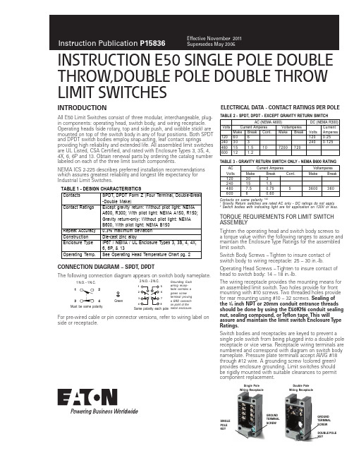
THROW,DOUBLE POLE DOUBLE THROW LIMIT SWITCHESINTRODUCTIONAll E50 Limit Switches consist of three modular, interchangeable, plug-in components: operating head, switch body, and wiring receptacle.Operating heads (side rotary, top and side push, and wobble stick) aremounted on top of the switch body in any of four positions. Both SPDTand DPDT switch bodies employ snap-acting, leaf contact springsproviding high reliability and extended life. All assembled limit switchesare UL Listed, CSA Certified, and rated with Enclosure Types 3, 3S, 4,4X, 6, 6P and 13. Obtain renewal parts by ordering the catalog numberlabeled on each of the three limit switch components.NEMA ICS 2-225 describes preferred installation recommendationswhich assures greatest reliability and longest life expectancy forIndustrial Limit Switches.TORQUE REQUIREMENTS FOR LIMIT SWITCHASSEMBL YTighten the operating head and switch body screws toa torque value within the following ranges to assure andmaintain the Enclosure Type Ratings for the assembledlimit switch.Switch Body Screws – Tighten to insure contact ofswitch body to wiring receptacle: 25 – 30 in.-lb.Operating Head Screws – Tighten to insure contact ofhead to switch body: 14 – 18 in.-lb.The wiring receptacle provides the mounting means foran assembled limit switch. Two holes provide for frontmounting with #10 screws. Two threaded holes providefor rear mounting using #10 – 32 screws. Sealing ofthe ½ inch NPT or 20mm conduit entrance threadsshould be done by using the E50KH6 conduit sealingnut, sealing compound, or T eflon tape. This willassure and maintain the limit switch Enclosure T ypeRatings.Switch bodies and receptacles are keyed to prevent asingle pole switch from being plugged into a double polereceptacle or vice versa. Receptacle wiring terminals arenumbered and correspond with diagram on switch bodynameplate. Pressure plate terminals accept AWG #18through #12 wire. A grounding screw (colored green)provides enclosure grounding. Limit switches shouldbe rigidly mounted with suitable clearances to permitcomponent replacement.CONNECTION DIAGRAM – SPDT, DPDTThe following connection diagram appears on switch body nameplate.ELECTRICAL DATA - CONTACT RATINGS PER POLEFor pre-wired cable or pin connector versions, refer to wiring label onside or receptacle.Contacts SPDT, DPDT Form Z (Four Terminal, Double-Break-Double Make)Contact Ratings Except gravity return: Without pilot light: NEMAA600, R300; With pilot light: NEMA A150, R150;Gravity return-only: Without pilot light: NEMAB600, With pilot light: NEMA B150Repeat Accuracy0.3% maximum deviationConstruction Die-cast zinc alloyEnclosure Type IP67 / NEMA / UL Enclosure Types 3, 3S, 4, 4X,6, 6P, & 13Operating Temp.See Operating Head Temperature Chart pg. 2TABLE 1 - DESIGN CHARACTERISTICS1 N.O. - 1 N.C.Must be same polarityGreen2 N.O. - 2 N.C.Same polarity each poleGrounding: Eachwiring recep-tacle contains agreen screwterminal provinga GRD connecti-on point ot themetal enclosure.16578SINGLEPOLEKEYGROUNDTERMINALSCREWGROUNDTERMINALSCREWDOUBLE POLEKEYSingle PoleWiring ReceptacleDouble PoleWiring ReceptacleTABLE 2 - SPDT, DPDT - EXCEPT GRAVITY RETURN SWITCHContacts on same polarity 1&21 Gravity Return switches are rated AC only - DC ratings do not apply.2 Switch bodies with indicating light are for application on 120V or less.AC (NEMA A600) DC (NEMA R300)Volts Current Amperes Voltamperes CurrentMake Break Cont.Make Break Volts Amperes1206061200.252403032400.12548015 1.510720072060012 1.2TABLE 3 - GRAVITY RETURN SWITCH ONLY - NEMA B600 RATINGAC Current Amperes VoltamperesVolts Make Break Cont.Make Break12030324015 1.54807.50.75 5360036060060.60Instructions Publication P15836Effective November 2011INSTRUCTION E50 SINGLE POLE DOUBLE T HROW,DOUBLE POLE DOUBLE T HROW LIMIT SWITCHESEATON CORPORATION SWITCH BODIES WITH INDICATING LIGHTSwitch bodies with the indicating light should be used at 120V or less. The light is factory-connected. The lamp may be reconnected by lifting the gasket and reconnecting the lightBottom View of Side Operated Rotary Head (Note Mode Change Instructions in Head)Self Operating Head ModeBefore AssemblyPush Operated - These spring return top push or side push operating heads are available in pushbutton and roller styles. The push roller style can be converted from vertical to horizontal operation or vice versa. Pull roller out of the head until it can be rotated 90° to the desired orientation. When released, it will snap into the set position. The Maintained Contact head has the reset pushbutton located opposite of the actuator pushbutton.INSTRUCTION E50 SINGLE POLE DOUBLE T HROW,DOUBLE POLE DOUBLE T HROW LIMIT SWITCHESInstructions Publication P15836Effective November 2011Mechanical life can be extended if the following guidelines are followed:a.) Cam arrangement should be such that: the actuator does not receive a severe impact; the actuator does not suddenly slip back freely.b.) Minimum amount of overtravel should be used. See NEMA ICS 2-225 for additional guidelines.SPECIAL PURPOSE LIMIT SWITCHESGravity Return Limit Switch - These limit switches require a very low operating force. Table 8. The weight of the rod-type lever supplies the return force instead of a return spring. Limit switchoperation is either CW or CCW, and may be mounted in any position where the shaft is horizontal (parallel to ground).Adjustment – After mounting in the selected position, adjust for proper operation. Set the rod extension and lock it in place with set-screw. Loosen other setscrew and rotate the INPUT SHAFT in the direction it will turn when operated (clockwise or counterclockwise) until a resistance is felt and a click is heard (contacts trip). Back the shaft away from this point until the contacts reset as indicated by another click – This is about 10°, the minimum pretravel for the Gravity Return limit switch. The shaft may be set for any desired pre-travel between 10° and 170° - at more than 170° the contacts may trip. In noisy locations, where the click of contact operation might not be heard, connect a test lamp in series with the normally open contacts for visual indication of contact operation. With the shaft set for the desired amount of pretravel, 10° to 170°, lock the operator in place with setscrew. Check for repeatable switch operation. Neutral Position Limit Switch - This spring return limit switch has two independently operated poles. One pole operates when the shaft rotates clockwise, and the other operates when the shaft is rotated counterclockwise. Both poles are reset in the neutral posi-tion (center off). See Table 8 below.T wo Step Limit Switch - The mode of operation of this side rotary operated two pole limit switch can be changed for CW, CCW or CW and CCW mode as described for the standard side rotary head on page 2. Two independently-operated poles function as a degree of head shaft rotation. One pole operates after 10° of shaft rotation and the second after an additional 10° of shaft rotation in the same direc-tion (20° total for step two). Both poles reset when the shaft returns to the spring return or neutral position.Side PushWobble HeadTABLE 7 - OPERATING HEAD DATAInstructions Publication P15836Effective November 2011INSTRUCTION E50 SINGLE POLE DOUBLE T HROW,DOUBLE POLE DOUBLE T HROW LIMIT SWITCHESTABLE 8 - OPERATING DATA - SPECIAL PURPOSE LIMIT SWITCHESGravity ReturnMust be Same Polarity CW CCWNeutral PositionTwo Step312 For CW or CCW only operation. For CW and CCW operation, operating temperature is -20DIMENSION DIAGRAM - Inches [mm]6TOP PUSH OPERATORS - mm [inches]Top Push Roller6Can accomodate both U.S., 29.4 [1.16] x 59.5 [2.34] and DIN,30 [1.18] x 60 [2.36] mounting options.SIDE PUSH OPERATORS - mm [inches]Side Push RollerSide Pushbutton MaintainedSide PushbuttonSide Pushbutton AdjustableTop Pushbutton Adjustable Top Pushbutton7 FOR E50DS48 FOR E50DS3Eaton Corporation Electrical Sector 1111 Superior Ave.Cleveland, OH 44114United States877-ETN-CARE (877-386-2273)© 2011 Eaton Corporation All Rights Reserved Printed in USAPublication No. P15836 / 003November 2011Eaton is a registered trademark of Eaton Corporation.All other trademarks are property of their respective owners.。
905中文说明书
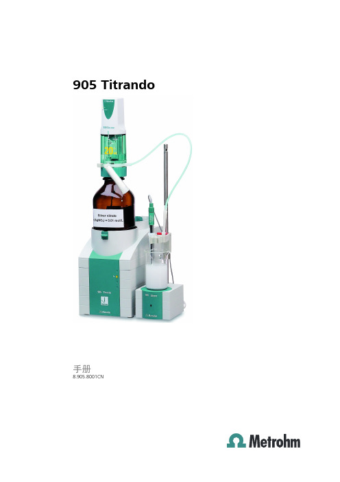
905 Titrando
■■■■■■■■ III
目录
■■■■■■■■■■■■■■■■■■■■■■
3.5.6 连接 iConnect ....................................................................... 23 3.5.7 电位差计 .............................................................................. 24
1.3 滴定模式 — 测量模式 — 滴定指令 ....................................... 2
1.4 手册说明 ................................................................................. 4 1.4.1 惯用图例 ................................................................................ 4
8.2 主机电源连接 ....................................................................... 33
8.3 安全描述 ............................................................................... 33
2 仪器概览
7
3 安装
9
3.1 3.1.1 3.1.2 3.1.3
设备组装 ................................................................................. 9 包装 ........................................................................................ 9 检查 ........................................................................................ 9 场地 ........................................................................................ 9
日本共立KEW 1051万用表中文使用说明书

DC 1000V 100MΩ 以上 AC 6.88kVrms AC / 5 秒(输入端口和外箱间) 约 192(L)×90(W)×49(D)mm 约 560g(含电池) IEC 61010-1 IEC61010-031 CAT.III (最大输入电压:AC/DC1000V) CAT.IV(最大输入电压:AC/DC 600V )污染度 2,室内,海拔 2000m 以下
4.操作
4.1 测试前注意事项 z 检测包装 打开包装后,请在使用前检查产品。若交货产品有错,有遗漏,产品表面有裂痕,请与经销商联系。 z 操作和保存的注意事项
频率测试 Hz 量程 10.00~99.99Hz 90.0~999.9Hz 0.900~9.999kHz 9.00~99.99kHz
分辨率 0.01 Hz 0.1 Hz 0.001 kHz 0.01 kHz
精确度 0.02+1
AC 结合,最大读数 9999 输入电压 0.02~600V rms
0.1~600V rms 0.8~100V rms
保存温湿度
-30℃~+70℃ 相对湿度 70%以下,无结露
温度系数
-10℃~18℃,28℃~55℃范围内,23℃±5℃时的精确度×0.1/℃
电源
R6/LR6(AA)1.5V×4
电池寿命
约 300 小时(直流电压测试中使用碱性干电时)注意:电池寿命取决于操作条件。
绝缘电阻 耐电压 外形尺寸 重量 安全规格
10A/1000V 保险丝 保护 10A
DC 电流测试
A
量程
分辨率
精确度
电压下降
50/60Hz 40Hz~1kHz
600µA 0.1µA
<0.12mV/µA
alliance 洗脱机 固定式机体 安装操作保养手册说明书

汞 (Hg)
镉 (Cd)
六价铬 (CR[VI])
聚溴联苯 (PBB)
聚溴二苯醚 (PBDE)
PCBs
X
O
O
O
O
O
机电部件
O
O
O
O
O
O
电缆和电线
O
O
O
O
O
O
金属部件
O
O
O
O
O
O
塑料部件
O
O
O
O
O
O
电池
O
O
O
O
O
O
软管和管道
O
O
O
O
O
O
同步带
O
O
O
O
O
O
绝缘材料
O
O
O
O
O
O
玻璃
O
O
O
O
O
O
显示
O
O
O
O
O
• 请勿在洗涤剂盒的喷嘴(如适用)上装贴任何物体。必 须为此保留空气间隙。
• 如洗衣机上未安装循环水塞或循环水系统(如适用), 则不可操作本机。
• 请确保在水管连接时安装截止阀,进水管间连接紧密。 在结束清洗的当天,务必关闭截止阀。
• 请妥善保养洗衣机。如洗衣机遭撞击或发生坠落,安全 功能可能会受到损坏。如发生此类情况,请联系合格服 务人员检查机器。
重要安全说明
警告
在使用洗衣设备时,为降低发生火灾、触电、人员重伤或 死亡等风险,请务必遵守这些基本注意事项:
W023
• 请在使用本洗衣机前通读所有说明。 • 请遵照本安装说明安装洗衣机。请参考安装手册中 有关
凱馳K5 高壓清洗機中文說明書说明书

1德國凱馳家用高壓清洗機K 5 中文說明書(一) 主機本體與配件名稱1. 快速接頭轉接環2. 高壓管快速接口3. 進水口(含過濾裝置)4. 電源開關ON/OFF5. 大型手提把6. 配件收納網7. 配件收納處8. 主機電源線9.清潔劑吸管附過濾嘴10. 大型滾輪與輪栓 11. 高壓槍把12. 高壓槍把安全鎖 13. 高壓管移除鎖 14. 高壓管 15. 螺旋噴桿16. 高低壓可調噴桿17. 自購水管,主機使用一般/棉質4分水管18.高壓槍把固定架(二) 安全提示使用本產品前,請遵守下列基本安全事項 - 第一次使用前,請務必詳閱本說明書。
- 請了解主機安裝、操作高壓與關閉主機方式。
- 請勿於身體不適時操作主機,以免發生危險。
- 請遵守本說明之配件使用、保養與維修資訊。
(三) 使用前 組件安裝步驟A 、安裝主機滾輪步驟B 、將主機手提把安裝於主機上,槍把固定架安裝於主機側邊步驟C 、安裝配件收納網,將收納網分別掛於兩側勾環內安裝快速進水接頭步驟D 、將高壓管插入噴槍內直到聽到「喀」 的聲音。
安裝後輕拉高壓管確認安裝妥當。
拆除高壓管與噴槍連接:按下高壓管移除鎖將高壓管移除。
步驟E/F 、將高壓管另一端直接插入主機高壓管快速接頭內並聽到「喀」確認已經固定。
移除高壓管時請將高壓快速接頭往外按壓拔除高壓管即可。
2步驟G 、安裝前請確實將槍把安全鎖鎖上。
安裝噴桿,請依照槍桿孔型將噴桿按壓入槍把孔內後逆時針方向鎖緊。
注意:請確認槍桿已確實固定於槍把上,以免造成危險。
步驟H 、使用清潔劑自吸功能。
請先行安裝高低壓可調式噴桿後。
將清潔劑吸管從主機後下方輕拉出,插入清潔劑中。
使用時請將高低壓噴桿調置低壓設定方能進行自吸清潔劑,清潔劑自吸需啟動槍把後1-2分鐘出清潔劑才會噴射出。
注意:請勿使用粉狀或過於濃稠清潔劑(沙拉脫)步驟I 、將大型手提把拉出移動,請確實拉出後聽到「喀」聲音表示固定。
收回時請往下按壓把手縮回把手。
Pearl旋转接头KC系列使用说明书

使用说明书编号: SE-20019-1发行: 20219 29Pearl 旋转接头KC 系列本使用说明书的适用对象是型式以KC, SKCL 开头的产品。
Pearl 是株式会社昭和技研工业产品的商品名称。
本使用说明书中记载着避免发生事故的重要注意事项及产品的使用方法。
为了安全使用产品,使用前请仔细阅读和理解使用说明书。
此外,请妥善保管,以便随时参阅。
目录1.铭牌的看法(铭牌的信息)---------------------------------------------------2.为了安全-------------------------------------------------------------------2-1)关于图标-----------------------------------------------------------------2-2)为了安全使用-------------------------------------------------------------3. 产品概要-------------------------------------------------------------------3-1)用途---------------------------------------------------------------------3-2)机种名称所表示的信息-----------------------------------------------------3-3)使用条件-----------------------------------------------------------------3-4)使用上的注意点-----------------------------------------------------------3-5)产品的结构和材质---------------------------------------------------------3-6)产品的尺寸---------------------------------------------------------------3-7)产品的质量---------------------------------------------------------------3-8)附属品-------------------------------------------------------------------4. 搬运和保管-----------------------------------------------------------------4-1)搬运---------------------------------------------------------------------4-2)保管---------------------------------------------------------------------5. 安装到机械上---------------------------------------------------------------5-1)内管(仅限于复式的情况)--------------------------------------------------5-2)安装在滚筒上-------------------------------------------------------------5-3)配管---------------------------------------------------------------------6. 从机械上拆卸---------------------------------------------------------------7. 运转-----------------------------------------------------------------------7-1)运转---------------------------------------------------------------------7-2)运转的休止---------------------------------------------------------------8. 点检和维护-----------------------------------------------------------------8-1)日常点检-----------------------------------------------------------------8-2)给脂---------------------------------------------------------------------8-3)消耗零件的维修/更换-------------------------------------------------------9. 故障检修-------------------------------------------------------------------10.废弃/处理------------------------------------------------------------------11.产品保修-------------------------------------------------------------------A.附录消耗品的维修/更换方法-------------------------------------------------A-1)单式的情况(KCL, KCLF, SKCL )---------------------------------------------A-2)复式内管固定螺纹安装的情况(KC )------------------------------------------A-3)复式内管固定法兰安装的情况(KCF )-----------------------------------------A-4)复式内管旋转式的情况(KCW, KCFW )---------------------------------------------P3P3P3P3P4P4P4P6P6P7P7P7P8P9P9P9P9P9P10P11P12P13P13P13P14P14P14P14P15P16P16P19P20P22P24P261.铭牌的看法(铭牌的信息)机种名称制造编号制造日期粘贴在产品上的铭牌上写有机种名称、制造编号及制造日期。
KCC1智能部件说明书

1 概述1.1KCC1型系列智能I/O部件,是KJ50型PROMOS监控系统中的主要产品,是PROMOS系统输入输出信息的转接设备,共有四个输入输出端口,每一端可连接一路传感器输入和一路执行元件的输出,不能单独使用,只能与PROMOS系统配套使用,按与外部设备相联的不同要求有五种方式。
KCC1型系列智能I/O部件,采用插头座连接。
KCC1A型智能I/O部件,采用接线端子连接。
KCC1B型智能I/O部件是在两个输出口中附加了SKR安全信号的控制部件。
KCC1C型智能I/O部件是在四个输出口中都加SKR安全输出信号的控制部件。
SKR安全输出信号,从硬件方面保证紧急停车的作用更加安全有效。
KCC1D型是以多块智能I/0部件为基础的灵活组合。
本产品适用于煤矿井下的有甲烷和煤尘爆炸性危险的环境中,其防爆型式为:矿用本质安全型。
防爆标志为:ExibI(150℃)。
其关联设备为KDW10型矿用直流稳压电源。
(隔爆兼本安型)其配接设备为:KJF21型控制器KJJ10型控制接口KJK3型系列辅助控制器KTK1型系列扩音电话KPG3型系列急停开关KDF1型系列线路终端KPA1型按钮KPG2型开关KZD2型电控阀等等以上设备全部为本质安全型。
1.2型号及其含义KC C 1变型序号A-D登记序号模、开I/O混合组件矿用信息传输装置及组件其中变型序号:A为引线端子式B为两路接点输出和两路安耦合接点输出C为四路接点输出和四路安耦合接点输出D为多块智能I/O部件为基础的各种组合7-21.3 使用环境及工作条件在下列环境条件下KCC1型系列智能I/O 部件应能正常工作: -工作环境温度:0-40℃;-平均相对湿度:不超过96%(+25℃); -大气压力:(80-106)kPa ;-有甲烷和煤尘爆炸性危险的矿井环境中;-允许有溅水但无破坏绝缘的腐蚀性气体的矿井中; -无剧烈振动和冲击的地方。
2结构特征 2.1 结构特征KCC1型系列智能I/O 部件的外壳是由钢板焊接而成的, 壳体的最小厚度均不小于3mm ,其中的零、部件有防锈防蚀处理,紧固件有防松动的措施,其中KCC1型系列的接线方式为插头座,KCC1A-D 型带有接线腔,腔内设有端子排,采用电缆引入装置,产品外形结构见图1。
Victor RC-E05 说明书

手提式CD音響當音響發生異常或有燒焦味時,應立即拔除電源插頭,若在異常狀態下繼續使用,易造成火災之發生。
請速與本公司服務專線聯絡或就近經銷商洽詢。
目錄(一)本機特點及緊急處理方法&警告 (2)(二)安全注意事項 (3)(三)免責聲明 (3)(四)外型及各部位名稱 (4)(五)安裝方法 (5)(六)規格 (5)(七)功能操作 (6)功能選擇 (6)音量調整 (6)調諧電台 (6)CD唱片的使用 (7)CD唱片的播放 (7)搜尋特定樂曲 (7)搜尋特定歌曲片段 (8)重複播放 (8)隨機播放 (8)外部音源功能 (8)程序播放記憶 (9)耳機使用 (9)(八)保養 (10)(九)故障排除 (10)1˙HI/FI立體聲˙具播放CD/收音機功能˙AM(MONO)/FM立體聲收音˙具有耳機插孔˙CD 20首曲目編輯˙具重複播放、單曲重複播放及隨機播放功能˙具外部音源輸入擴音功能2在使用本機之前,應仔細閱讀下列事項及使用說明,閱後並請妥為收存,以備將來參考:1.本機請勿置於雨中、濕氣中或避免陽光直射及遠離其他會產生熱能的裝置。
2.本機放置位置請勿太靠近電視、電腦、錄影機及手機,以免遭受干擾,產生誤 動作。
003.使用本機的工作溫度為5~35C。
4.長期不使用本機時,應將其電源線插頭從插座內拔出。
5.請勿將雜物或液體從機身開口處進入機身內部。
6.當本機出現下列情況時,應請合格的維修人員進行維修:A:故障或液體落入本機內。
B:雜物或液體落人本機內。
C:受到雨淋。
D:無法正常操作或性能出現明顯變化。
E:不慎跌落或外殼受損。
7.請勿擅自拆下任何蓋子、內部裝置或調校內部裝置,請交由本公司專業人員進 行維修。
8.使用耳機時,請勿將音量調太大聲,以免聽力受損。
9.當耳朵產生耳鳴時,應將音量調小或取消耳機使用。
10.當使用開放式耳機時,請勿將音量調太大聲,以避免聽不到周遭的聲音。
3●聲明:本機CD讀取機構,出廠時皆經標準測試,一般原廠CD讀取皆能正常讀取,對於消費者自行燒錄的CD片,本公司建議以最低燒錄整度來燒錄CD。
前途k50用户手册电子版

前途k50用户手册电子版一、前途k50的启动与停止用root用户启/停需要root用户包含在前途k50m组中。
1、前途k50的启动str前途k50mQMgrName如果启动默认队列管理器,str前途k50m后可以忽略队列管理器名称。
在意外情况停止队列管理器后,启动可能会失败,此时可以检查上次停止后是否有IPC资源未释放,若有请予以删除,删除方法参考下面的“C、清理所有残留在系统内部的信号灯和共享内存”。
2、前途k50的关闭一般情况下,我们使用“end前途k50m-iQMgrName”来停止前途k50,如果停止失败,可以使用如下步骤:步骤1:end前途k50m-pQMgrName,如果停不掉,继续步骤2:杀死有关进程,清理残留在系统内部的信号灯和共享内存A、找到队列管理器程序进程ps-ef|grepQMgrNameB、使用kill命令终止1&gt;中找到的程序进程,无法停止的进程可以用kill-9来终止,终止进程的顺序如下(不存在的进程可以忽略):killa前途k50pcsea命令服务器killa前途k50hasmx记录器killa前途k50harmx日志格式化器(仅LINEAR日志)killa前途k50zllp0检查点处理器killa前途k50zlaa0队列管理器代理killa前途k50zxma0处理控制器killa前途k50rrmfa库进程(用于群集)C、清理所有残留在系统内部的信号灯和共享内存(其属主和组均为前途k50m)二、前途k50运行状态查看与常用操作1、查看队列管理器运行状态对前途k505、2或以上版本,执行如下命令检查队列管理器运行状态:dsp前途k50显示结果中QMNAME表示前途k50队列管理器的名称,STATUS表示当前运行状态。
运行状态有如下几种:Starting正在启动Running正在运行Ending正在停止Endednormally已经正常终止Endedimmediately已经立即终止Endedpreemtively已经强制终止Endedunexpectively异常终止注意:停止前途k50后必须使用dsp前途k50命令进行状态检查dsp前途k50查询结果示例:QMNAME(QM00)STATUS(Running)2、run前途k50sc查看通道运行状态与启停通道dischl(*);查看所有通道定义dischs(*);查看所有通道状态,如果没有查询到通道状态,或报错A 前途k508420:ChannelStatusnotfound,请启动通道dischs(ChannelName);查看通道ChannelName的状态通道状态有如下几种:STARTING正在启动BINDING正在绑定INITIALIZING正在初始化RUNNING正常STOPPING正在停止RETRYING重试PAUSED等待STOPPED已停止REQUESTING请求startchl(ChannelName);启动通道stopchl(ChannelName);停止通道resetchannel(ChannelName);重置通道序号。
