FM1288中文数据手册仅供参考
1288说明书

版本号: 4.1日期: May 2008版本号更新记录超日期注意恭喜你购买了采用SLSI芯片和低电压宽脉冲发射技术设计的DCT1288超声波流量计。
本操作手册包含重要的流量计使用和操作信息,请仔细阅读以使你的流量计发挥最佳性能,防止流量计损坏和不正当使用。
本操作手册将以循序渐进的方式介绍如何使用流量计,由流量计的产品组成开始,安装、接线、快速设置,让你容易的使用流量计。
通过了解更多的菜单设置,让流量计强大的功能选项和输出功能满足你的更高要求。
警告本手册上及流量计上带有“警告标志”或“警告”是指:如果不遵守有关要求、不采取相应措施,就存在着造成人身伤害或损坏流量计的潜在危险。
注意本手册上及流量计上带有“注意标志”或“注意”是指:如果不遵守有关要求、不采取相应措施,就存在着损坏流量计或导致流量计不能正常测量的潜在危险。
本说明书中的一些内容可能与你购买的流量计不同,取决于选购时的配置要求;另一方面由于产品的设计更改和升级需要,在说明书中没有注明,请留意版本号以及增加的附页说明。
产品组成请在安装流量计之前检查备件是否与装箱清单内容相符,确保不存在潜在的损坏、螺丝脱落等,如有任何疑问,请及时与供应商联系。
目录1.变送器的安装和接线 (7)1.1. 检查变送器安装 (7)1.2. 电源接线 (7)1.2.1. 电源类型 (7)1.2.2. 变送器接线 (7)1.3. 通电 (8)1.4. 键盘 (8)1.5. 键盘操作方法 (9)1.6. 流量计窗口简介 (10)2.快速设定菜单说明 (12)3.选择测量点 (13)4.传感器安装 (14)4.1. 传感器安装注意事项 (14)4.2. 传感器安装 (14)4.2.1. 安装间距 (15)4.2.2. 传感器的安装类型 (16)4.2.3. V型 (16)4.2.4. Z型 (16)4.2.5. N型(不常用) (16)4.2.6. W型(很少用) (16)4.3. 安装检查 (17)4.3.1. 信号强度 (17)4.3.2. 信号质量(Q值) (17)4.3.3. 总传输时间、时差 (17)4.3.4. 传输时间比 (17)4.2.5 安装时需注意的问题 (18)5.操作说明 (19)5.1. 连接和使用掌上电脑 (19)5.2. 蓝牙连接 (19)5.3. 系统工作状态判断 (19)5.4. 全屏幕显示数据 (20)5.5. 流量单位制 (20)5.7. 累积流量单位 (20)5.8. 累积器倍乘因子 (20)5.9. 打开或关闭流量累积器 (20)5.10. 流量累积器清零 (20)5.11. 出厂设置的恢复 (21)5.12. 设置流量阻尼器 (21)5.13. 零点切除 (21)5.14. 零点设置 (21)5.15. 仪表系数 (21)5.16. 密码保护 (21)5.17. 键盘锁 (22)5.18. 4~20mA 电流环输出 (22)5.19. 模拟电压信号输出 (22)5.20. 修改日期时间 (22)5.21. 查询每日、每月、每年流量 (22)5.22. 实现断电时间段内流量的自动补加 (22)5.23. 使用工作计时器 (23)5.24. 使用手动累积器 (23)5.25. 模拟输出校准 (23)5.26. DCT1288软件操作 (23)5.26.1 数据采集和分析处理 (24)5.26.1.1 掌上电脑数据采集和分析处理程序 (24)5.26.1.2. 程序主界面菜单 (24)5.26.1.3. 数据采集 (24)5.26.1.4. 数据分析处理及曲线图 (25)5.26.1.5. 内置SD卡数据采集控制 (27)5.26.1.6. 读取内置SD卡采集数据 (28)5.26.2. UFMData数据分析处理和打印程序 (28)5.26.2.1. 数据浏览和打印 (29)5.26.2.2. 曲线显示及打印 (29)5.26.2.3. 数据分析及打印 (30)5.26.2.4. 配置信息显示 (31)5.26.2.5. 菜单功能 (32)5.26.3. 流量计设置向导 (32)5.26.3.2. 流量计显示设置 (35)5.26.3.3. 模拟量输出和时间设置 (36)5.27. 序列号 (37)6.窗口菜单介绍 (38)6.1. 菜单一览表 (38)6.2. 菜单详解 (39)7.故障分析 (54)7.1. 问题回答 (56)8.产品概述 (58)8.1. 产品介绍 (58)8.2. 产品特点 (58)8.3. 工作原理 (58)8.4. 应用范围 (59)8.5. 技术指标 (60)9.附录1 –常用流体数据表 (61)9.1. 常用液体声速和粘度 (61)9.2. 常用材料声速 (61)9.3. 不同温度下水的声速表(1个标准大气压) (62)10.附录2 – DCT1288软件在掌上电脑上的安装 (63)10.1. UFMData程序的安装 (64)10.1.1. 硬件要求 (64)10.1.2. 操作系统要求 (64)10.1.3. 安装方法 (64)更新信息:__________________________________________________________________________________________ __________________________________________________________________________________________ __________________________________________________________________________________________ __________________________________________________________________________________________1.变送器的安装和接线1.1.检查变送器安装安装流量计前,请检查仪表、备件是否与装箱单内容相符,检查是否有螺丝脱落、连线松动等问题,如有请妥善处理,如运输中机壳受到了挤压等损坏,请尽快与我们联系。
FM1288中文数据手册

图 13:IIS 的上升沿锁存,LRCK 高左声道,1 个周期的延迟.........................29
图 14:IIS 的上升沿锁存,LRCK 高左声道,0 个周期的延迟.........................30
图 15:IIS 的上升沿锁存,LRCK 高为右声道,1 个周期的延迟.....................30
图 4 : fm-1288Biblioteka 例 如 表 格1 单独的最小系
统....................................................................15
图 5:例如 UART 协议..............................................................................................22
图 10:IIS 的下降沿锁存,LRCK 高左声道,0 个周期的延迟..........................28
图 11:IIS 的下降沿锁存,LRCK 高为右声道,1 个周期的延迟.....................28
图 12:IIS 的下降沿锁存,LRCK 高为右声道,0 个周期的延迟.....................29
4
状态信息
本产品数据表的状态是产品信息。
预报 关于富迪产品开发设计人员的信息。文档中指定的所有值都是设计的目标
值。如果指定的最小值和最大值,仅作为指导到最终规格的限制,并且不能被视 为最终的值。
所有的详细规格,包括引脚电气规格没有通知情况下也可能被富迪改变。
预生产信息
引脚和机械尺寸规格定稿。文档中指定的所有值都是设计的目标值。如果指 定的最小值和最大值,仅作为指导到最终规格的限制,并且不能被视为最终的值。
FM1288中文数据手册(仅供参考)

FM-1288 高性能汽车免提语音理器产前信息本文件包含一个试制产品信息。
规格和试生产资料如有更改恕不另行通知。
富迪科技有限公司的产品并不是为了挽救生命或维持生命的应用。
因此,如果这样使用的话迪科技有限公司不承担任何责任。
富迪的产品有富迪的书面批准才能用于生命支持设备或系统。
如果有这样的组件故障可合理预期会导致该生命支持设备或系统的失效,或影响的设备或系统的安全性或有效性。
生命支持设备或系统的目的是植入人体,或支持和/或维持和维持和/或保护人类生活。
如果他们失败了,这个假设合理,用户或其他人的健康可能会受到威胁。
在此我们拒绝任何形式的担保,但不限于保证不侵权,还包括对于电路说明和图表说明。
Fortémedia, SAM, ForteVoice, Fortémedia and SAM logos are trademarks of Fortémedia,, Inc.All other trademarks belong to their respective companies.Copyright © 2012 Fortémedia all rights reserved目录1. 简介 (9)1.1概述 (9)1.2个主要特点 (9)1.3引脚配置(LQFP) (10)1.4设备终端功能 (11)1.5内部硬件框图 (14)1.6系统应用程序框图 (15)2. 功能描述 (17)2.1概述 (17)2.2串行EEPROM接口(引脚15,16) (17)2.3 UART接口(引脚12,13) (22)2.4 IIC兼容串行接口-SHI(引脚23,24) (24)2.5数字语音数据接口(引脚8,9,10,11) (25)2.5.1 PCM接口主从 (26)2.5.2 IIS接口 (28)2.6 ADC(引脚39,40,41,42,43,44) (33)2.7 DAC(引脚 1,3,47,48) (34)2.8操作模式 (35)2.9电STAP选项(引脚17) (37)2.10静音控制和指示(引脚20,21) (37)2.11扬声器音量控制(引脚25,26) (38)2.12系统时钟输入和产生(引脚27,28) (38)2.13旁路模式(引脚14) (39)3.通过EEPROM,UART,SHI访问fm1288 (40)3.1访问通过EEPROM (41)3.2 通过实例访问EEPROM (42)3.3通过UART访问 (43)3.5通过SHI访问 (44)3.6个例子通过施 (44)4. 电气和时序规范 (44)4.1绝对最大额定值 (45)4.2推荐操作条件 (45)4.3直流特性 (46)4.4交流特性 (47)4.5时序特性 (49)5. 语音处理器性能细节 (52)6. 引脚定义细节 (53)7. 封装尺寸(LQFP) (55)8. 订货信息 (56)附录 I:操作所需的外部元件 (57)参考 (59)状态信息本产品数据表的状态是产品信息。
史赛克1288摄像系统
3
Warnings
To avoid potential serious injury to the user and the patient and/or damage to this device, please note the following warnings: 1. Carefully unpack this unit and check if any damage occurred during
Operating the Camera with a Light Source....... 27
Troubleshooting............................................... 28
Cleaning, Reprocessing, and Maintenance....... 31
1288 HD Video Camera
User Guide
1288010000 1288010001 1288210105 1288710105
Contents
Warnings and Cautions...................................... 3
Product Description and Intended Usபைடு நூலகம்............... 6
Indications/Contraindications.......................................................7 The Camera Console....................................................................8 The Camera Head......................................................................10 The C-Mount Coupler.................................................................11
emva_1288_rela2.01_official

9 9 9 9 9 9
7 MODULE 1: CHARACTERIZING THE IMAGE QUALITY AND SENSITIVITY OF MACHINE VISION CAMERAS AND SENSORS 7.1 7.2 7.3 7.3.1 7.3.2 7.4 7.4.1 7.4.2 8 8.1 MATHEMATICAL MODEL MEASUREMENT SETUP MATCHING THE MODEL TO THE DATA EXTENDED P HOTON T RANSFER METHOD SPECTROGRAM METHOD PUBLISHING THE RESULTS CHARACTERIZING T EMPORAL NOISE AND SENSITIVITY CHARACTERIZING T OTAL AND SPATIAL NOISE
About this Standard
EMVA has started the initiative to define a unified method to measure, compute and present specification parameters and characterization data for cameras and image sensors used for machine vision applications. The standard does not define what nature of data should be disclosed. It is up to the component manufacturer to decide if he wishes to publish typical data, data of an individual component, guaranteed data, or even guaranteed performance over life time of the component. However the component manufacturer shall clearly indicate what the nature of the presented data is. The Standard is organized in different modules, each addressing a group of specification parameters, assuming a certain physical behavior of the sensor or camera under certain boundary conditions. Additional modules covering more parameters and a wider range of sensor and camera products will be added at a later date. There are “COMPULSORY” modules, of which all measurements must be made and of which all required data and graphics must be included in a datasheet using the EMVA1288 logo. Further there are “OPTIONAL” modules which may be skipped for a component where the respective data is not relevant or the mathematical model is not applicable. Each datasheet shall clearly indicate which modules of the EMVA1288 standard are enclosed. For the time being it may be necessary for the manufacturer to indicate additional, component specific information, not defined in the standard, to fully describe the performance of image sensor or camera products, or to describe physical behavior not covered by the mathematical models of the standard. It is possible in accordance with the EMVA1288 standard to include such data in the same datasheet. However the data obtained by procedures not described in the current version of the EMVA1288 standard must be clearly designated and grouped in a separate section. It is not permitted to use parameter designations defined in any of the EMVA1288 modules for such additional information not acquired or presented according the EMVA1288 procedures.
FM系列硬件系统手册

PROFIBUS-DP 总线及设备 ................................................................................................. 31
Profibus-DP 总线简介 ......................................................................................................................... 31
1993-2004 Copyright Hollysys
和利时、HollySys、HOLLiAS 及
的商标或注册商标。
的字样和徽标均为和利时系统工程股份有限公司
Microsoft、Windows 和 WindowsNT 是微软公司在美国和/或其他国家分支机构的商标或注册商 标。
手册中涉及到的其他商标或注册商标属于他们各自的拥有者。
供电系统及接地要求.......................................................................................................................... 20
供电系统说明........................................................................................................................................................... 20 接地要求................................................................................................................................................................... 21
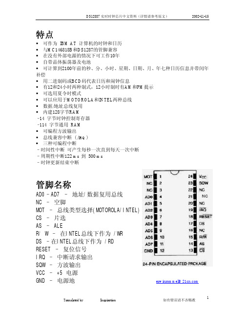
DS12887实时时钟芯片中文资料(详情请参考原文)
1
1
1.953125ms
1
0
0
0
3.90625ms
1
0
0
1
7.8125ms
1
0
1
0
15.625ms
1
0
1
1
31.25ms
1
1
0
0
62.5ms
1
1
0
1
125ms
1
1
1
0
250ms
1
1
1
1
500ms
SQW 输出频率
无 256 Hz 128 Hz 8.192 kHz 4.096kHz 2.048 kHz 1.024kHz 512Hz 256Hz 128Hz 64Hz 32Hz 16Hz
管脚功能
MOT (总线模式选择) 当此脚接到VCC 时,选用的是MOTOROLA总线时序; 当它接到地或不接时,选用的是INTEL总线时序。
SQW (方波输出) – 当VCC低于4.25V时没有作用。
Translated by Lyang Inspiration
如有错误请不吝赐教
2
DS12887 实时时钟芯片中文资料(详情请参考原文)
R/W (Read/Write Input) –WR
CS (片选输入) –CS 当VCC 低于4.25 V时,DS12887 从内部禁止对外部CS的操作。此时,时钟和RAM 都被保护起来。
IRQ (中断请求输出) – 当中断状态位和对应的中断允许位有效时,IRQ的输出保持为低。复位和读C寄存器 都可以清除IRQ中断信号。没有中断时,IRQ呈高阻状态,其他中断源还可以挂接到 中断总线上。由于IRQ是漏极输出,所以需要外接上拉电阻。
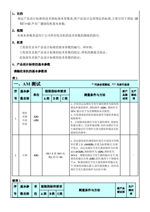
收音机的产品设计标准收音机的基本参数收音机国标
极限指标和要求
测量条件与方法
新产品测试项
生产测试项
A类
B类
C类
14
降压ห้องสมุดไป่ตู้性
产品标准规定
1、设定高频信号发生器的频率为中端,调制频率1KHz,调制度为30%,输出电平为106dB;
2、调谐接收机的接收频率为中端并微调信号发生器使接收机准确调谐PVC,音量最大;
3、当电压降至额定值的倍时,此时输出功率应不小于标准输出功率;
\
续表1
序号
基本参数名称
单位
极限指标和要求
测量条件与方法
新产品测试项
生产测试项
A类
B类
C类
6
镜象抑制中波
dB
34
20
--
1、设定高频信号发生器的频率为高端,调制频率1KHz,调制度为30%;
2、调谐接收机的接收频率为高端并微调高频信号发生器的频率,使接收机准确调谐PVC;
3、微调高频信号发生器的输出电平为限噪灵敏度,并调整接收机的音量使输出为标准输出,记下此时高频发生器的输出电平为U;
1、目的
规定产品设计标准的技术指标基本参数表,使产品设计达到预定的标准,主要引用于国标GB9374-88声音广播接收机基本参数;
2、范围
本基本参数表适用于公司所有收音机的技术参数的测量的指引;
3、权责
工程部负责本产品设计标准的基本参数的编写、和审核;
工程部负责新产品设计标准的技术参数的拟定,样机的测量及验证;
品保部负责新产品设计标准的技术参数的验证;
4、产品设计标准的基本参数
调幅收音机的基本参数表
表1
一、AM测试“”代表必须测试,“\”代表可选项
序号
(完整word版)EMVA1288中文翻译

1介绍和范围2灵敏度、线性度和噪声2.1线性信号模型2.2噪声模型2.3信噪比(SNR)2.4信号饱和度和绝对灵敏度阈值3暗电流3.1均值和方差3.2温度依赖4空间不均匀性和缺陷像素4.1空间差异,DSNU,PRNU4.2类型的不均匀性4.3缺陷像素4.3.1对数直方图4.3.2累积直方图4.4高通滤波5概述测量的建立和方法6灵敏度、线性度和噪音6.1均质光源的几何形状6.2光源的光谱特性6.3辐照变异6.4校准辐照6.5对线性度和灵敏度的测量条件6.6根据光子传递法对测量结果进行评价6.7线性评价7暗电流7.1在一个温度下对暗电流的评价7.2 对温度的暗电流的评价8空间不均匀性和缺陷像素8.1空间标准偏差,DSNU,PRNU和total SNR 8.2水平和垂直光谱图8.3缺陷像素特征9光谱灵敏度9.1光谱光源设置9.2测量条件9.3校准9.4评估10出版结果10.1基本信息10.2 EMVA 1288参数10.3 EMVA 1288数据表A参考书目B表示法C版本A2.01更改C.1增加的功能C.2将方法扩展到不同的照射C.3条件和程序的修改C.4极限时间标准偏差; 量化噪声介绍C.5具有不均匀度测量的高通滤波D版本3.0的变化2灵敏度、线性度和噪声本节描述了如何描述灵敏度、线性度和时间噪声图像传感器或摄像机[3,4,6,8]。
2.1线性信号模型如图1所示,数字图像传感器实际上是将曝光时间内的光子通过一系列步骤转换成数字。
在曝光时间内,平均µp光子冲击单个像素。
整个量子效率的一小部分吸收并积累µe电荷单位。
这里定义的总量子效率是指单个传感器elementpixel所占用的总面积,而不仅仅是光敏感区域。
因此,这个定义包括填充因子和微透镜的影响。
在公式(1)中表示,量子效率取决于光子辐照像素的波长。
在暴露时间t exp内,与区域a相对应的光子的平均数目,可以通过以W / m2为单位的传感器表面的辐照度来计算使用著名的电磁辐射的能量量子化单位hν。
B1-38028FM产品数据手册说明书

Product Datasheet28-Port10G Uplink Layer Three Managed Ethernet SwitchB1-38028FMOVERVIEWThe B1-38028FM series is a10G uplink managed Ethernet fiber switch independently developed by BISMON.It has24*10/100/1000Base-T RJ45ports and4*1/10G SFP+fiber slot ports.Each port can support wire-speed forwarding.The B1-38028FM has the layer three full network management function,supports IPV4/IPV6management,supports static route full line rate forwarding,supports complete security protection mechanism,complete ACL/QoS policy and rich VLAN functions,and is easy to manage and maintain.Supports multiple network redundancy protocols STP/RSTP/MSTP(<50ms)and(ITU-T G.8032)ERPS to improve link backup and network reliability.When one-way network fails,communication can be quickly restored to ensureimportant Uninterrupted communication for applications.According to the actual application requirements,you can configure multiple application services such as port traffic control,VLAN division,and SNMP through the Web network management mode.It satisfies high-density network application environment and is suitable for medium, large-scale scenes such as hotels,campuses,parks,shopping malls,scenic spots, hospitals,banks,etc.to form an economical,efficient and reliable communication network.FEATURE⏹Gigabit access,10G uplink◇All series supports“Gigabit Ethernet port and10G SFP+uplink port“combination, which enables users to flexibly build networking to meet the needs of variousscenarios.◇Support non-blocking wire speed forwarding.◇Support full duplex based on IEEE802.3x and half duplex based on backpressure.⏹Strong business processing capability◇Support IEEE802.1Q VLAN,users can flexibly divide VLAN according to needs,and support QinQ configuration.◇Support QoS,support port based,802.1P based and DSCP based three priority modes and Equ,SP,WRR,SP+WRR four queue scheduling algorithms.◇ACL supports the filtering of data packets by configuring matching rules,processing operations and time permissions,and provides a flexible access control strategy.◇Support IGMP V1/V2multicast protocol and support IGMP Snooping to meet the multi terminal HD video surveillance and video conference access requirements.◇Support STP/RSTP/MSTP production tree protocol,eliminates two layers of loops, and realizes link backup.◇Support G.8032industrial fast Ring network ERPS Protocol network convergence time≤20ms◇Support static convergence and dynamic convergence,effectively increases link bandwidth,achieves load balancing,link backup,and improves link reliability.⏹Complete safety protection mechanism◇Support802.1X authentication,provide authentication function for LAN computer,and control the authorized status of controlled port according to the result ofauthentication.◇Support port isolation◇Support port broadcast storm suppression◇Support port+MAC binding,IP+MAC+port binding function⏹The equipment is stable and reliable◇The host has low power consumption,no fan mute design,aluminum alloy metal shell, excellent heat dissipation,and ensure stable operation of products.◇The equipment meets the national CCC standard,fully meets the requirements of CE, FCC and RoHS safety regulations,and is safe and reliable.◇BISMON-developed power supply,high redundancy design,provides long-term stable PoE power◇The user can easily understand the working status of the device through the power indicator(PWR),system status indicator(SYS),and port status indicator(Link/Act) operation indicator.⏹Easy operation and maintenance management◇Support various management and maintenance methods such as Web management, CLI command line(Console,Telnet),SNMP(V1/V2/V3).◇Support encryption methods such as HTTPS,SSLV3,and SSHV1/V2for more secure management.◇Support RMON,system log,port traffic statistics,easy network optimization and transformation.◇Support LLDP,which is convenient for the network management system to query and judge the communication status of the link.◇Support CPU monitoring,memory monitoring,ping detection,cable length detection. TECHNICAL SPECIFICATIONDIMENSIONAPPLICATIONPACKING LISTNote:Ethernet switch does not match the optical module by default.If you need to purchase it,please refer to the accessory product information.ORDERING INFORMATIONSELECTION OF INFORMATIONFiber Module Selection Table。
IS62WV1288ALL_datasheet
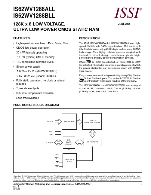
IS62WV1288ALL IS62WV1288BLLISSI®Copyright © 2005 Integrated Silicon Solution, Inc. All rights reserved. ISSI reserves the right to make changes to this specification and its products at any time without notice. ISSI assumes no liability arising out of the application or use of any information, products or services described herein. Customers are advised to obtain the latest version of this device specification before relying on any published information and before placing orders for products.128K x 8 LOW VOLTAGE,ULTRA LOW POWER CMOS STATIC RAMFEATURES•High-speed access time: 45ns, 55ns, 70ns •CMOS low power operation:30 mW (typical) operating 15 µW (typical) CMOS standby •TTL compatible interface levels •Single power supply:1.65V--2.2V V DD (62WV1288ALL) 2.5V--3.6V V DD (62WV1288BLL)•Fully static operation: no clock or refresh required •Three state outputs•Industrial temperature available •Lead-free availableDESCRIPTIONThe ISSI IS62WV1288ALL / IS62WV1288BLL are high-speed, 1M bit static RAMs organized as 128K words by 8bits. It is fabricated using ISSI 's high-performance CMOS technology. This highly reliable process coupled with innovative circuit design techniques, yields high-performance and low power consumption devices.When CS1 is HIGH (deselected) or when CS2 is LOW (deselected), the device assumes a standby mode at which the power dissipation can be reduced down with CMOS input levels.Easy memory expansion is provided by using Chip Enable and Output Enable inputs. The active LOW Write Enable (WE ) controls both writing and reading of the memory.The IS62WV1288ALL and IS62WV1288BLL are packaged in the JEDEC standard 32-pin TSOP (TYPEI), sTSOP (TYPEI), SOP, and 36-pin mini BGA.FUNCTIONAL BLOCK DIAGRAMJUNE 20052Integrated Silicon Solution, Inc. — — 1-800-379-4774Rev.C IS62WV1288ALL, IS62WV1288BLLISSI®PIN DESCRIPTIONSA0-A16Address Inputs CS1Chip Enable 1 Input CS2Chip Enable 2 Input OE Output Enable Input WE Write Enable Input I/O0-I/O7Input/Output NC No Connection V DD Power GNDGround36-pin mini BGA (B) (6mm x 8mm)32-pin TSOP (TYPE I) (T),32-pin sTSOP (TYPE I) (H)PIN CONFIGURATION32-pin SOP (Q)1 2 3 4 5 6A B C D E F G HA0I/O4I/O5GND V DD I/O6I/O7A9A1A2OE A10CS2WE NCNCCS1A11A3A4A5NC A16A12A6A7A15A13A8I/O0I/O1V DD GNDI/O2I/O3A141234567891011121314151632313029282726252423222120191817A11A9A8A13WE CS2A15V DD NC A16A14A12A7A6A5A4OE A10CS1I/O7I/O6I/O5I/O4I/O3GND I/O2I/O1I/O0A0A1A2A31234567891011121314151632313029282726252423222120191817NC A16A14A12A7A6A5A4A3A2A1A0I/O0I/O1I/O2GNDV DD A15CS2WE A13A8A9A11OE A10CS1I/O7I/O6I/O5I/O4I/O3IS62WV1288ALL, IS62WV1288BLL ISSI®ABSOLUTE MAXIMUM RATINGS(1)Symbol Parameter Value UnitV TERM Terminal Voltage with Respect to GND–0.2 to V DD+0.3VV DD V DD Related to GND–0.2 to +3.8VT STG Storage Temperature–65 to +150°CP T Power Dissipation 1.0WNote:1.Stress greater than those listed under ABSOLUTE MAXIMUM RATINGS may cause permanent damage to the device. This isa stress rating only and functional operation of the device at these or any other conditions above those indicated in theoperational sections of this specification is not implied. Exposure to absolute maximum rating conditions for extended periods may affect reliability.OPERATING RANGE (V DD)Range Ambient Temperature IS62WV1288ALL IS62WV1288BLLCommercial0°C to +70°C 1.65V - 2.2V 2.5V - 3.6VIndustrial–40°C to +85°C 1.65V - 2.2V 2.5V - 3.6VDC ELECTRICAL CHARACTERISTICS (Over Operating Range)Symbol Parameter Test Conditions V DD Min.Max.Unit V OH Output HIGH Voltage I OH = -0.1 mA 1.65-2.2V 1.4—VI OH = -1 mA 2.5-3.6V 2.2—VV OL Output LOW Voltage I OL = 0.1 mA 1.65-2.2V—0.2VI OL = 2.1 mA 2.5-3.6V—0.4VV IH(2)Input HIGH Voltage 1.65-2.2V 1.4V DD + 0.2V2.5-3.6V 2.2V DD + 0.3VV IL(1)Input LOW Voltage 1.65-2.2V–0.20.4V2.5-3.6V–0.20.6VI LI Input Leakage GND ≤ V IN≤ V DD–11µAI LO Output Leakage GND ≤ V OUT≤ V DD, Outputs Disabled–11µA Notes:1.Undershoot: –1.0V for pulse width less than 10 ns. Not 100% tested.2. Overshoot: V DD + 1.0V for pulse width less than 10 ns. Not 100% tested.TRUTH TABLEMode WE CS1CS2OE I/O Operation V DD CurrentNot Selected X H X X High-Z I SB1, I SB2(Power-down)X X L X High-Z I SB1, I SB2Output Disabled H L H H High-Z I CCRead H L H L D OUT I CCWrite L L H X D IN I CC4Integrated Silicon Solution, Inc. — — 1-800-379-4774Rev.C IS62WV1288ALL, IS62WV1288BLLISSI®AC TEST LOADSFigure 1Figure 2CAPACITANCE (1)Symbol Parameter Conditions Max.Unit C IN Input Capacitance V IN = 0V 8pF C OUTInput/Output CapacitanceV OUT = 0V10pFNote:1.Tested initially and after any design or process changes that may affect these parameters.AC TEST CONDITIONSParameter62WV1288ALL 62WV1288BLL (Unit)(Unit)Input Pulse Level0.4V to V DD -0.2V0.4V to V DD -0.3VInput Rise and Fall Times 5 ns 5ns Input and Output Timing V REF V REF and Reference Level Output LoadSee Figures 1 and 2See Figures 1 and 21.65V -2.2V2.5V -3.6V R1(Ω)30703070R2(Ω)31503150V REF 0.9V 1.5V V TM1.8V2.8VIS62WV1288ALL, IS62WV1288BLL ISSI®POWER SUPPLY CHARACTERISTICS(1)(Over Operating Range)62WV1288ALL (1.65V - 2.2V)Symbol Parameter Test Conditions Max.Unit70 nsI C C V DD D ynamic O perating V DD=M ax.,Com.8m ASupply C urrent I OUT = 0 mA, f = f MAX Ind.8typ.(2)5I CC1Operating S upply V DD=M ax.,Com.5m ACurrent I OUT = 0 mA, f = 0Ind.5I SB1TTL Standby Current V DD=M ax.,Com.0.8m A(TTL Inputs)V IN = V IH or V IL Ind.0.8CS1 = V IH , CS2 = V IL,f = 1 MH ZI SB2CMOS S tandby V DD=M ax.,Com.10µACurrent (CMOS Inputs)CS1≥V DD – 0.2V,Ind.10CS2 ≤ 0.2V,typ.(2)5V IN≥V DD – 0.2V, orV IN≤ 0.2V, f = 0Note:1.At f = f MAX, address and data inputs are cycling at the maximum frequency, f = 0 means no input lines change.2. Typical values are measured at V DD=1.8V, T A=25o C. Not 100% tested.POWER SUPPLY CHARACTERISTICS(1)(Over Operating Range)62WV1288BLL (2.5V - 3.6V)Symbol Parameter Test Conditions Max.Max.Unit45ns55 nsI C C V DD D ynamic O perating V DD= Max.,Com.1715m ASupply C urrent I OUT = 0 mA, f = f MAX Ind.1715typ.(2)1210I CC1Operating S upply V DD= Max.,Com.55m ACurrent I OUT = 0 mA, f = 0Ind.55I SB1TTL Standby Current V DD= Max.,Com.0.80.8m A(TTL Inputs)V IN = V IH or V IL Ind.0.80.8CS1 = V IH , CS2 = V IL,f = 1 MH ZI SB2CMOS S tandby V DD= Max.,Com.1010µACurrent (CMOS Inputs)CS1≥V DD – 0.2V,Ind.1010CS2 ≤ 0.2V,typ.(2)55V IN≥V DD – 0.2V, orV IN≤ 0.2V, f = 0Note:1.At f = f MAX, address and data inputs are cycling at the maximum frequency, f = 0 means no input lines change.2. Typical values are measured at V DD=3.0V, T A=25o C. Not 100% tested.IS62WV1288ALL, IS62WV1288BLL ISSI®READ CYCLE SWITCHING CHARACTERISTICS(1)(Over Operating Range)45 ns 55 ns70 nsSymbol Parameter Min.Max.Min.Max.Min.Max.Unit t RC Read Cycle Time45—55—70—ns t AA Address Access Time—45—55—70ns t OHA Output H old T ime10—10—10—ns t ACS1/t ACS2CS1/CS2 A ccess T ime—45— 55—70ns t DOE OE Access Time—20—25—35ns t HZOE(2)OE to High-Z Output015020025ns t LZOE(2)OE to Low-Z Output5—5—5—ns t HZCS1/t HZCS2(2)CS1/CS2 t o H igh-Z O utput015020025ns t LZCS1/t LZCS2(2)CS1/CS2 t o L ow-Z O utput5—10—10—ns Notes:1.Test conditions assume signal transition times of 5 ns or less, timing reference levels of 0.9V/1.5V, input pulse levels of 0.4 toV DD-0.2V/V DD-0.3V and output loading specified in Figure 1.2.Tested with the load in Figure 2. Transition is measured ±500 mV from steady-state voltage. Not 100% tested.AC WAVEFORMSREAD CYCLE NO. 1(1,2) (Address Controlled) (CS1 = OE = V IL,CS2 = WE = V IH)6Integrated Silicon Solution, Inc. — — 1-800-379-4774Rev.CIS62WV1288ALL, IS62WV1288BLL ISSI®AC WAVEFORMSREAD CYCLE NO. 2(1,3)(CS1,CS2, OE Controlled)Notes:1.WE is HIGH for a Read Cycle.2.The device is continuously selected. OE, CS1= V IL. CS2=WE=V IH.3.Address is valid prior to or coincident with CS1 LOW and CS2 HIGH transition.IS62WV1288ALL, IS62WV1288BLL ISSI®WRITE CYCLE SWITCHING CHARACTERISTICS(1,2) (Over Operating Range)45 ns 55 ns70 nsSymbol Parameter Min.Max. Min.Max. Min.Max.Unit t WC Write Cycle Time45— 55— 70—ns t SCS1/t SCS2CS1/CS2 t o W rite E nd35—45— 60—ns t AW Address Setup Time to Write End 35—45— 60—ns t HA Address Hold from Write End0—0—0—ns t SA Address S etup T ime0—0—0—ns t PWE WE P ulse W idth35—40—50—ns t SD Data Setup to Write End20—25—30—ns t HD Data Hold from Write End 0—0—0—ns t HZWE(3)WE LOW to High-Z Output—20—20—20ns t LZWE(3)WE HIGH to Low-Z Output5—5—5—ns Notes:1.Test conditions assume signal transition times of 5 ns or less, timing reference levels of 0.9V/1.5V, input pulse levels of 0.4Vto V DD-0.2V/V DD-0.3V and output loading specified in Figure 1.2.The internal write time is defined by the overlap of CS1 LOW, CS2 HIGH, and WE LOW. All signals must be in valid states to initiate a Write, but any one can goinactive to terminate the Write. The Data Input Setup and Hold timing are referenced to the rising or falling edge of the signal that terminates the write.3.Tested with the load in Figure 2. Transition is measured ±500 mV from steady-state voltage. Not 100% tested.AC WAVEFORMSWRITE CYCLE NO. 1 (CS1/CS2 Controlled, OE = HIGH or LOW)8Integrated Silicon Solution, Inc. — — 1-800-379-4774Rev.CIS62WV1288ALL, IS62WV1288BLL ISSI®AC WAVEFORMSWRITE CYCLE NO. 2 (WE Controlled: OE is HIGH During Write Cycle)IS62WV1288ALL, IS62WV1288BLL ISSI®DATA RETENTION SWITCHING CHARACTERISTICSSymbol Parameter Test Condition Min.Max.Unit V DR V DD for Data Retention See Data Retention Waveform 1.2 3.6VI DR Data Retention Current V DD = 1.2V, CS1≥ V DD – 0.2V—5µAt SDR Data Retention Setup Time See Data Retention Waveform0—ns t RDR Recovery Time See Data Retention Waveform t RC—nsDATA RETENTION WAVEFORM (CS1 Controlled)DATA RETENTION WAVEFORM (CS2 Controlled)10Integrated Silicon Solution, Inc. — — 1-800-379-4774Rev.CIS62WV1288ALL, IS62WV1288BLL ISSI®ORDERING INFORMATIONIS62WV1288ALL (1.65V - 2.2V)Industrial Range: -40°C to +85°CSpeed (ns)Order Part No.Package70IS62WV1288ALL-70BI mini BGA (6mm x 8mm)IS62WV1288ALL-70HI sTSOP, TYPE IIS62WV1288BLL (2.5V-3.6V)Industrial Range: -40°C to +85°CSpeed (ns)Order Part No.Package45IS62WV1288BLL-45TI TSOP, TYPE IIS62WV1288BLL-45BI mini BGA (6mm x 8mm)IS62WV1288BLL-45HI sTSOP, TYPE IIS62WV1288BLL-45QI SOP55IS62WV1288BLL-55TI TSOP, TYPE IIS62WV1288BLL-55TLI TSOP, TYPE I, Lead-freeIS62WV1288BLL-55BI mini BGA (6mm x 8mm)IS62WV1288BLL-55HI sTSOP, TYPE IIS62WV1288BLL-55HLI sTSOP, TYPE I, Lead-freeIS62WV1288BLL-55QI SOPIS62WV1288BLL-55QLI SOP, Lead-freePACKAGING INFORMATIONISSI®Copyright © 2003 Integrated Silicon Solution, Inc. All rights reserved. ISSI reserves the right to make changes to this specification and its products at any time without notice. ISSI assumes no liability arising out of the application or use of any information, products or services described herein. Customers are advised to Mini Ball Grid ArrayPackage Code: B (36-pin)PACKAGING INFORMATIONISSI®Copyright © 2003 Integrated Silicon Solution, Inc. All rights reserved. ISSI reserves the right to make changes to this specification and its products at any time without notice. ISSI assumes no liability arising out of the application or use of any information, products or services described herein. Customers are advised to 450-mil Plastic SOPPackage Code: Q (32-pin)PACKAGING INFORMATION ISSI®Plastic STSOP - 32 pinsPackage Code: H (Type I)PACKAGING INFORMATIONISSI®Copyright © 2003 Integrated Silicon Solution, Inc. All rights reserved. ISSI reserves the right to make changes to this specification and its products at any time without notice. ISSI assumes no liability arising out of the application or use of any information, products or services described herein. Customers are advised to Plastic TSOP-Type IPackage Code: T (32-pin)。
【精品】短波收音机收听手册

短波收音机收听手册当下市面上的全波段(WorldBand)数调短波收音机调谐的频率跨度很大,典型的调谐范围从150KHz到30000KHz,几乎囊括长波、中波、短波的全部波段。
根据国际无线电联盟的协定,无线电频率被划分并供应给不同用途的使用者。
虽然偶有犯规者,但绝大多数台(站)都恪守许可使用的频率.150KHz及以下.这个频率的无线电波不能通过电离层传播,却可以很好地穿透海洋的深处,因此,在这个频率下可以发现许多做潜艇通讯的军事电台.德国、英国、日本、瑞士和白俄罗斯等国的标准时间标准频率发播台的发射频率都在20-80khz之间,普通收音机是根本接收不到的。
150到540KHz。
这是BCLer和Dxer通称的长波段。
在收音机里能听到的大多数信号是一些信标台不断重复摩尔斯(Morse)电码呼号.长波广播从153KHz启用,大功率的长波广播以俄罗斯和东欧国家为甚,非洲及澳大利亚、蒙古和前苏联加盟共和国等部分亚太地区国家也有长波广播,但我国广播并未染指这一领地。
法国标准时间标准频率发播台使用162khz.在长波的高端,可以接收到一些RTTY(无线电传)信号。
海洋气象和安全广播,如无线电爱好者熟知的VTEX(航行警告自动通信系统)就是在512KHz发射。
这个波段的最好接收时间是秋冬季的夜晚。
我国的北方地区容易接收到独联体国家的长波广播。
540KHz到1710KHz。
这是中波广播.亚洲和中南美洲地区的中波起始段被划为530KHz。
传统收音机的中波到1600KHz结束,而实际意义上的中波广播波段却在1710KHz结束。
从1610到1710KHz是新的中波扩展领域,从1997年开始,不断有电台在这一波段上播音,给无线电爱好者提供了精彩的DX(远程无线电接收活动)契机。
但1700khz以上频率入驻的中波广播电台寥寥无几,据WRTH(《世界广播电视手册》)最新记录,全球仅有两家广播电台在1700khz—-1710khz发声,澳大利亚转播当地赛马和服务偏远地区土著民的广播电台就使用1701KHz,阿根廷RadioPalacio—AM1710电台使用1710KHz,发射功率均在1KW以下,远程接收极具挑战性。
FM收音机_RDS功能概述及编码
FM收音机_RDS功能概述及编码RDS功能的FM收音机概述及编码介绍所谓RDS是英国BBC广播公司开发的一种特殊无线电广播。
即“无线数据广播系统”(Radio Data System). 它是在调频广播发射信号中利用副载波把电台名称,节目类型,节目内容及其它信息以数字形式发送出去。
1概述通过具有RDS功能的调谐器就可以识别这些数字信号,并做响应处理,RDS广播精髓在于其AF和TA功能,AF既自动频率调整,当信号低于某个水平时,AF功能会自动搜索当前电台的其他发射频率串。
2功能RDS收音系统还独有“交流信息”功能(TA功能,也称交通公告),若有紧急事件,电台就会发送特殊信号,令收音机强行播放,另外,还有时间基准发射,自动调准收音机时间等功能,RDS在汽车,手机等移动设备上使用很方便。
3电台支持目前国内支持RDS的电台已知的有:上海FM91.4 中央人民广播电台经济之声北京FM88.7 中国国际广播电台HIT FM上海FM87.9 中国国际广播电台HIT FM广州FM88.5 中国国际广播电台HIT FMRDS是英国BBC广播公司开发的一种特殊的无线电广播,称“无线数据广播系统”(Radio Data System),它是在调频广播发射信号中利用副载波把电台名称、节目类型、节目内容及其它信息以数字形式发送出去。
通过具有RDS功能的调谐器就可以识别这些数字信号,变成字符显示在显示屏上。
在收到节目的同时,通过RDS可知道接收到的是那个电台,它的发射频率,并给出该电台其余的频率,由此再使用“切换频率”钮来保证所接收的信号为最强的频率。
RDS无线数据广播文件可显示接收到的节目名称及其它资料。
RDS功能可按节目类型决定取舍,寻找到符合你要求的电台。
RDS还能用来自动控制接收机,使流动工作的汽车收音机一直保持最佳接收状态,及时收到紧急交通报告,有利交通安全。
RDS 除使收音机自动化、高档化外,并在城市交通管理中发挥作用,其使用领域尚在拓展中随着发展,会有越来越多的电台具有RDS广播功能,RDS可以显示电台名称、节目类型、节目内容、日期时间及其它信息,而它具有的AF和TA功能,则更强大。
TEL T826 827 FM基站传输器与激发器说明书
1T826/827 General InformationThis section provides a brief description of the T826 transmitter and T827 exciter, along with detailed specifications and a list of types available.The following topics are covered in this section.Section Title Page 1.1Introduction 1.31.21.2.11.2.21.2.31.2.41.2.4.11.2.4.21.2.4.31.2.51.2.6SpecificationsIntroductionGeneralRF SectionAudio ProcessorInputsModulation CharacteristicsCTCSSMicrocontrollerTest Standards1.41.41.41.51.61.61.71.71.71.81.3Product Codes 1.9 1.4T826 Standard Product Range 1.10 1.5T827 Standard Product Range 1.101.1IntroductionThe T826 is a synthesised, microprocessor controlled FM base station transmitter designed for single or multichannel operation in the 66 to 88MHz frequency range1 with a standard power output of 25W. The RF section of the transmitter comprises a fre-quency synthesiser which provides 125mW of frequency modulated RF drive to a two stage, wide band output driver followed by a 25W power amplifier. A thermal shut-down feature is provided in the T826 in case operating temperatures exceed acceptable levels.The T827 is a synthesised, microprocessor controlled FM base station exciter designed for single or multichannel operation in the 66 to 88MHz frequency range1. With a stand-ard power output of only 1W, the exciter is designed for use with the T828 50W power amplifier. The RF section of the exciter comprises a frequency synthesiser which pro-vides 125mW of frequency modulated RF drive to a two stage, wide band output ampli-fier.A wide selection of audio characteristics may be obtained from the audio processor. Optional circuit blocks are an audio compressor and a pre-emphasis stage. They can be bypassed or linked to one or both audio inputs, and then back into the remaining audio circuitry in almost any combination. All audio processor options are link selectable. The synthesiser frequency is programmed via the serial communications port. Eight channel select lines are accessible via an optional D-range connector (D-range 2 -T800-03-0000) at the rear of the set.All components except those of the VCO are mounted on a single PCB. This is secured to a die-cast chassis which is divided into compartments to individually shield each sec-tion of circuitry. Access to both sides of the main circuit board is obtained by removing each of the chassis lids. There is provision within the chassis to mount small option PCBs.The front panel controls include line sensitivity, microphone socket and carrier switch. This switch turns on the carrier (unmodulated) as an aid to servicing.The T826 and T827 are both 60mm wide and each occupies a single space in a Tait rack frame, which has the ability to accommodate up to seven standard modules.1.Although capable of operating over the 66-88MHz frequency range, the T826 and T827have an 8MHz switching range (see Section 1.2.3 and Section 3.1).1.2Specifications1.2.1IntroductionThe performance figures given are minimum figures, unless otherwise indicated, for equipment tuned with the maximum switching range and operating at standard room temperature (+22°C to +28°C) and standard test voltage (13.8V DC).Where applicable, the test methods used to obtain the following performance figures are those described in the EIA and ETS specifications. However, there are several parameters for which performance according to the CEPT specification is given. Refer to Section 1.2.6 for details of test standards.Details of test methods and the conditions which apply for Type Approval testing in all countries can be obtained from Tait Electronics Ltd.The terms "wide bandwidth" and "narrow bandwidth" used in this and following sec-tions are defined in the following table.1.2.2GeneralNumber Of Channels ..128 (standard)1Supply V oltage:Operating V oltage ..10.8 to 16V DC Standard Test V oltage ..13.8V DCPolarity..negative earth only Polarity Protection..crowbar diode Line Keying Supply (if required) ..-50V DCSupply Current:Transmit - T826.. 4.5A (typical)- T827..650mAStandby..160mA (typical)Operating Temperature Range..-30°C to +60°CChannel SpacingModulation 100% DeviationReceiver IF Bandwidth Wide Bandwidth 25kHz ±5.0kHz 15.0kHz Narrow Bandwidth12.5kHz±2.5kHz7.5kHz1.Additional channels may be factory programmed. Contact your nearest Tait Dealer or Customer Service Organisation.Dimensions:Height ..183mm Width ..60mmLength ..322mmWeight .. 2.1kgTime-Out Timer (optional) ..0 to 5 minutes1 adjustable in 10 sec-ond stepsTail Timer ..0 to 5 seconds adjustable in 100ms2stepsTransmit Key Time..<30msTransmit Lockout Timer..0 to 1 minute adjustable in 10 secondsteps1.2.3RF SectionFrequency Range ..66-88MHz (refer to Section 1.4 andSection 1.5)Modulation Type ..FMFrequency Increment .. 5 or 6.25kHzSwitching Range ..8MHz (i.e. ±4MHz from the centrefrequency)Load Impedance ..50 ohmsFrequency Stability..±2.5ppm, -30°C to +60°C(see also Section 1.4 and Section 1.5)Adjacent Channel Power (full deviation):Wide Bandwidth (WB)..-70dBc(±25kHz/15kHz B/W)Narrow Bandwidth (NB)..-60dBc(±12.5kHz/7.5kHz B/W)Transmitter plies with ETS 300 113Transmitter Side Band Noise:(no modulation, 15kHz bandwidth)At ±25kHz ..-95dBcAt ±1MHz ..-105dBc1.Adjustable from 0 to 10 minutes in PGM800Win version2.12 and later.2.Adjustable in 20ms steps in PGM800Win version 2.12 and later.Intermodulation ..-40dBc with interfering signal of-30dBc..-70dBc with 25dB isolation& interfering signal of -30dBc(PA with output isolator)T826 Mismatch Capability:Ruggedness ..refer to your nearest Tait Dealer orCustomer Service Organisation Stability ..3:1 VSWR (all phase angles) Radiated Spurious Emissions:Transmit ..-36dBm to 1GHz-30dBm 1GHz to 4GHz Standby ..-57dBm to 1GHz-47dBm 1GHz to 4GHzConducted Spurious Emissions: (T826 Only)Transmit..-36dBm to 1GHz-30dBm 1GHz to 4GHz Standby..-57dBm to 1GHz-47dBm 1GHz to 4GHzPower Output:T826- Rated Power..25W- Range Of Adjustment..5-25WT827..1W ±300mWDuty Cycle (T826 Only)..100% @ 25W at +25°C..30% @ 25W at +60°C..100% @ 10W at +60°C1.2.4Audio Processor1.2.4.1InputsInputs Available ..line, microphone and CTCSSLine Input:Impedance ..600 ohms (balanced)Sensitivity (60% modulation @ 1kHz)-With Compressor ..-50dBmWithout Compressor ..-30dBmMicrophone Input:ohms Impedance ..600Sensitivity (60% modulation @ 1kHz)-With Compressor ..-70dBmWithout Compressor ..-50dBm1.2.4.2Modulation CharacteristicsFrequency Response ..flat or pre-emphasised (optional) (below limiting)Line And Microphone Inputs:Pre-emphasised Response-Bandwidth ..300Hz to 3kHz (WB)..300Hz to 2.55kHz (NB)Below Limiting ..within +1, -3dB of a 6dB/octavepre-emphasis characteristic Flat Response ..within +1, -2dB of output at 1kHz Above Limiting Response ..within +1, -2dB of a flat response(ref. 1kHz)Distortion ..2% max.Hum And Noise:Wide Bandwidth ..-55dB (300Hz to 3kHz [EIA]) typical Narrow Bandwidth..-50dB (CEPT)Compressor (optional):Attack Time ..10msDecay Time ..800msRange ..50dB1.2.4.3CTCSSStandard Tones..all 37 EIA group A, B and C tonesplus 13 commonly used tones Frequency Error..0.08% max.(from EIA tones)Generated Tone Distortion.. 1.2% max.Generated Tone Flatness..flat across 67 to 250.3Hz to within 1dB Modulation Level..adjustableModulated Distortion..<5%1.2.5MicrocontrollerAuxiliary Ports:Open Drain Type..capable of sinking 2.25mA via 2k2ΩV ds max (5V)1.2.6Test StandardsWhere applicable, this equipment is tested in accordance with the following standards.1.2.6.1European Telecommunication StandardETS 300 086 January 1991Radio equipment and systems; land mobile service; technical characteristics and test conditions for radio equipment with an internal or external RF connector intended pri-marily for analogue speech.ETS 300 113 March 1996Radio equipment and systems; land mobile service; technical characteristics and test conditions for radio equipment intended for the transmission of data (and speech) and having an antenna connector.ETS 300 219 October 1993Radio equipment and systems; land mobile service; technical characteristics and test conditions for radio equipment transmitting signals to initiate a specific response in the receiver.ETS 300 279 February 1996Radio equipment and systems; electromagnetic compatibility (EMC) standard for pri-vate land mobile radio (PMR) and ancillary equipment (speech and/or non-speech). 1.2.6.2DTI CEPT Recommendation T/R-24-01Annex I: 1988Technical characteristics and test conditions for radio equipment in the land mobile service intended primarily for analogue speech.Annex II: 1988Technical characteristics of radio equipment in the land mobile service with regard to quality and stability of transmission.1.2.6.3Telecommunications Industry AssociationANSI/TIA/EIA-603-1992Land mobile FM or PM communications equipment measurement and performance standards.1.3Product CodesThe three groups of digits in the T820 Series II product code provide information about the model, type and options fitted, according to the conventions described below.The following explanation of T820 Series II product codes is not intended to suggest that any combination of features is necessarily available in any one product. Consult your nearest Tait Dealer or Customer Service Organisation for more information regarding the availability of specific models, types and options.ModelThe Model group indicates the basic function of the product, as follows:T82X-XX-XXXX T825receiverT82625W transmitterT827exciterT82850W power amplifierTypeThe Type group uses two digits to indicate the basic RF configuration of the product.The first digit in the Type group designates the frequency range:T82X-X X-XXXX’1’ for 66-88MHzThe second digit in the Type group indicates the channel spacing:T82X-X X-XXXX’0’ for wide bandwidth (25kHz)’5’ for narrow bandwidth (12.5kHz)OptionsT82X-XX-XXXX The Options group uses four digits and/or letters to indicateany options that may be fitted to the product. This includesstandard options and special options for specific customers.’0000’ indicates a standard Tait product with no options fitted.The large number of options precludes listing them here.1.4T826 Standard Product RangeThe following table lists the range of standard T826 types (i.e. no options fitted) availa-ble at the time this manual was published. Consult your nearest Tait Dealer or Cus-tomer Service Organisation for more information.You can identify the transmitter type by checking the product code printed on a label on the rear of the chassis (Figure 1.1 in Part A shows typical labels). You can further verify the transmitter type by checking the placement of an SMD resistor in the table that is screen printed onto the PCB (refer to Section 6.1 for more details).1.5T827 Standard Product RangeThe following table lists the range of standard T827 types (i.e. no options fitted) availa-ble at the time this manual was published. Consult your nearest Tait Dealer or Cus-tomer Service Organisation for more information.You can identify the exciter type by checking the product code printed on a label on the rear of the chassis (Figure 1.1 in Part A shows typical labels). You can further verify the exciter type by checking the placement of an SMD resistor in the table that is screen printed onto the PCB (refer to Section 6.1 for more details).Frequency Range (MHz)66-88Deviation (kHz) 2.55TCXO aa. A TCXO with a stability of ±1ppm (0°C to +60°C) isavailable to suit specific requirements. Contact your nearest authorised Tait Dealer or Customer Service Organisation for further details.±2.5ppm -30°C to +60°C••Transmitter Type: T826-15-000010-0000Frequency Range (MHz)66-88Deviation (kHz) 2.55TCXO aa. A TCXO with a stability of ±1ppm (0°C to +60°C) isavailable to suit specific requirements. Contact your nearest authorised Tait Dealer or Customer Service Organisation for further details.±2.5ppm -30°C to +60°C••Transmitter Type: T827-15-000010-0000。
1008调频对讲收音机实验报告
长春建筑学院电气信息学院《认识实习》实习报告实习性质:认识实习(2周)专业:通信工程班级: 1502姓名:吴东旭学号:152000223指导教师:范亚芹时间:2016年6月20日-7月1日一、实习目的:通过实习了解通信工程专业在各行各业中的应用,对本专业在大学四年中将要学的内容有一个初步了解,使学生初步建立专业思想,掌握通信工程专业的焊接工艺流程、掌握芯片2822、1800的功能等,培养学生实际动手分析问题和解决问题的能力;本次实习主要是对1008调频对讲收音机的焊接,通过元器件介绍、电路工作原理的认识,掌握焊接电路板的工艺、调频对讲收音机的安装与调试工作,加深学生对本专业的认识,使学生热爱通信工程专业,从而产生兴趣。
二、实习要求:1、了解现代通信技术的发展过程2、掌握1008调频对讲收音机的安装顺序3、掌握1008调频对讲收音机的焊接技术4、了解集成电路芯片2822、1800的功能5、理解1008调频对讲收音机原理电路图6、完成两台机对讲和调试6、掌握焊接工艺。
三、实习内容:1008调频对讲收音机焊接(1)元器件介绍:【1-1】La1800芯片La1800为单片FM/AM收音机电路,F M部分包含混频,F M本振中放,FN鉴频,静噪,低通滤波器等;AM 部分包括高放检波,此外还有音频驱动级和功放电路。
芯片采用密间距的22脚双列直插封装,如图【1-2】D2822芯片用于收音机作音频功率放大器,经过CD2822放大后的音频信号从LA1800芯片输出,经过R10、C25、RP耦合至D2822芯片进行第二次功率放大,推动扬声器发出声音,该芯片包含两个放大二极管,工作电源电压范围为2.5V~5V。
采用密间距的8 脚双列直插封装,如图【1-3】电阻本实验中使用时色环电阻,色环电阻识别方法是因为电阻上面用了四道色环或者五道色环来表示电阻值。
四色环电阻中,第一色环是十位数,第二色环是个位数,第三色环是应乘颜色次幂颜色次,第四色环是误差率带有四个色环的其中第一、二环分别代表阻值的前两位数;第三环代表倍率;第四环代表误差。
FM1288 Configuration Manual
FM1288 Configuration ManualFM-1288High Performance Voice Processor for Automotive HandsfreeUser Configuration Manual (Product Information) version 0.6Sep 20, 2021 2 UCM-FM1288 V06PRE-PRODUCTION INFORMATIONTHIS DOCUMENT CONTAINS INFORMATION ON A PREPRODUCTION PRODUCT. SPECIFICATIONS AND PREPRODUCTIONINFORMATION HEREIN ARE SUBJECT TO CHANGE WITHOUT NOTICE.FORTEMEDIA, INC. PRODUCTS ARE NOT INTENDED FOR LIFE SAVING NOR LIFE SUSTAINING APPLICATIONS AND FORTEMEDIA,INC. THUS, ASSUMES NO LIABILITY IN SUCH USAGES. FORTEMEDIA, INC. PRODUCTS MAY ONLY BE USED IN LIFE-SUPPORTDEVICES OR SYSTEMS WITH THE EXPRESS WRITTEN APPROVAL OF FORTEMEDIA, INC., IF A FAILURE OF SUCH COMPONENTSCAN REASONABLY BE EXPECTED TO CAUSE THE FAILURE OF THAT LIFE-SUPPORT DEVICE OR SYSTEM, OR TO AFFECT THESAFETY OR EFFECTIVENESS OF THAT DEVICE OR SYSTEM. LIFE SUPPORT DEVICES OR SYSTEMS ARE INTENDED TO BEIMPLANTED IN THE HUMAN BODY, OR TO SUPPORT AND/OR MAINTAIN AND SUSTAIN AND/OR PROTECT HUMAN LIFE. IF THEYFAIL, IT IS REASONABLE TO ASSUME THAT THE HEALTH OF THE USER OR OTHER PERSONS MAY BE ENDANGERED. WE HEREIN DISCLAIM ANY AND ALL WARRANTIES, INCLUDING BUT NOT LIMITED TO WARRANTIES OF NON-INFRINGEMENT,REGARDING CIRCUITS, DESCRIPTIONS AND CHARTS STATED HEREIN.Fortémedia, SAM, ForteVoice, Fortémedia and SAM logos are trademarks of Fortémedia,, Inc. All other trademarks belong to their respective companies. Copyright ? 2021 Fortémedia all rights res erved Sep 20, 2021 3 UCM-FM1288 V06TABLE OF CONTENTSTATUSINFORMATION .................................................................. ........................................... 4 1.0OVERVIEW ..................................................................... .. (7)2.0 GLOSSARY ANDNOTATION ..................................................................... ........................... 7 3.0 GENERALCONFIGURATION ................................................................ ................................ 8 3.1 DEFAULT PROFILESETUP ........................................................................ ........................... 8 3.2 BANDWIDTH CONTROLSELECTION..................................................................... ............... 8 3.3 SINGLE MICROPHONE HANDS-FREE APPLICATION RECOMMENDED SETTINGS (9)4.0 MICROPHONE SIGNAL CONDITIONS FOR FM-1288 ......................................................... 10 5.0 DEBUGGING SUPPORTINFORMATION .................................................................. ........... 11 5.1 BYPASSMODES ........................................................................ ......................................... 13 6.0 PERFORMANCETUNING ....................................................................... ............................. 14 6.1 GAINFLOW ......................................................................... . (14)6.2 ACTIVITY DETECTORS(VAD) ........................................................................ .................... 17 7.0 PERFORMANCE TUNING PROCEDUREDETAILS ................................................................18 7.1 LINEARAEC .......................................................................... ............................................. 18 7.2 FREQUENCY DOMAIN ACTIVITYDETECTORS ...................................................................19 7.3 FREQUENCY DOMAIN NOISESUPPRESSION .................................................................. .. 20 7.4 FREQUENCY DOMAIN ECHOCANCELLATION ................................................................. ... 23 7.5 LINEOUTEQUALIZER .................................................................... .................................... 26 7.6 COMFORT NOISEFILL ......................................................................... .............................. 28 7.7 FAR END NOISE SUPPRESSION(FENS) ....................................................................... ..... 29 7.8 BRIGHT VOICE ENHANCEMENT(BVE) ........................................................................ ...... 32 7.9 BANDWIDTH EXTENSION(BWE) ........................................................................ .............. 33 7.10 FAR FIELD PICKUP(FFP) ........................................................................ (34)8.0 FM-1288 PARAMETERTABLE ........................................................................ .. (36)REFERENCES ................................................................... ........................................................ 54 I.TERMINOLOGY .................................................................. .............................................................................. .... 54 II. RELATEDDOCUMENTS .................................................................... . (55)Sep 20, 2021 4 UCM-FM1288 V06Status InformationThe status of this User’s Configuration Manual is Production Information. Advance InformationInformation for designers concerning Fortemedia product in development.All values specified in the document are the target values of the design.Minimum and maximum values, if specified, are only given as guidance to the final specification limits and must not be considered as the final values. All detailed specifications including pinouts and electrical specifications may be changed by Fortemedia without notice.Pre-production InformationPinout and mechanical dimension specifications finalized. All values specified in the document are the target values of the design. Minimum and maximum values, if specified, are only given as guidance to the final specification limits and must not be considered as the final values. All electrical specifications may be changed by Fortemedia without notice.Product InformationFinal User’s Configuration Manual including the guaranteed minimum and maximum limits for the electrical specifications.Product User’s Configuration Manual supersede all previous document versions.NoteWhile every case has been taken to ensure the accuracy of the contents in this Data Sheet, Fortemedia cannot accept responsibility for any errors. Fortemedia reserves the right to make technical changes to its products as part of its development program.Sep 20, 2021 5 UCM-FM1288 V06TABLESTable 1: Single Microphone Hands-Free ApplicationSettings ................................................... 9 Table 2: Air-tight Condition forMicrophones................................................................... ......... 10 Table 3: DebuggingSignals....................................................................... ................................ 11 Table 4: Signal Paths and Gains of BypassModes ...................................................................13 Table 5: Bypass Modes keyparameters ................................................................... ................ 13 Table 6: Linear AECparameters.................................................................... . (18)Table 7: Voice Activity Detectors - VAD01, VAD02, VAD03, VAD04,VAD05 (19)Table 8: Frequency Domain Noise Suppression (FDNS)parameters (20)Table 9: Frequency Domain Echo Controlparameters (23)Table 10: Line-out Equalizerparameters.................................................................... .............. 26 Table 11: Far End Noise Suppression (FENS) parameters....................................................... 29 Table 12: Bright Voice Enhancement (BVE)parameters (32)Table 13: Far Field Pickupparameters ................................................................... .................. 34 Table 14: FM-1288 ParameterTable......................................................................... ................ 36 Table 15:Terminology .................................................................. ............................................. 54 Table 16: RelatedDocuments .................................................................... . (55)Sep 20, 2021 6 UCM-FM1288 V06Document HistoryRevision Date Description0.1 Feb 20, 2021 Early Draft, original publication date0.2 March 25, 2021 Editorial updates, 1st draft Advance Information 0.3 June 04, 2021 Yan Tang, First Release Draft0.4 July 01, 2021 Yan Tang, AiGuo Zhang, Harry Liu, et al. First Release version 0.5 July 03, 2021 AiGuo Zhang, editorial updates感谢您的阅读,祝您生活愉快。
- 1、下载文档前请自行甄别文档内容的完整性,平台不提供额外的编辑、内容补充、找答案等附加服务。
- 2、"仅部分预览"的文档,不可在线预览部分如存在完整性等问题,可反馈申请退款(可完整预览的文档不适用该条件!)。
- 3、如文档侵犯您的权益,请联系客服反馈,我们会尽快为您处理(人工客服工作时间:9:00-18:30)。
FM-1288 高性能汽车免提语音理器产前信息本文件包含一个试制产品信息。
规格和试生产资料如有更改恕不另行通知。
富迪科技有限公司的产品并不是为了挽救生命或维持生命的应用。
因此,如果这样使用的话迪科技有限公司不承担任何责任。
富迪的产品有富迪的书面批准才能用于生命支持设备或系统。
如果有这样的组件故障可合理预期会导致该生命支持设备或系统的失效,或影响的设备或系统的安全性或有效性。
生命支持设备或系统的目的是植入人体,或支持和/或维持和维持和/或保护人类生活。
如果他们失败了,这个假设合理,用户或其他人的健康可能会受到威胁。
在此我们拒绝任何形式的担保,但不限于保证不侵权,还包括对于电路说明和图表说明。
Fortémedia, SAM, ForteVoice, Fortémedia and SAM logos are trademarks of Fortémedia,, Inc.All other trademarks belong to their respective companies.Copyright © 2012 Fortémedia all rights reserved目录1. 简介 (8)1.1概述 (8)1.2个主要特点 (8)1.3引脚配置(LQFP) (9)1.4设备终端功能 (9)1.5内部硬件框图 (12)1.6系统应用程序框图 (13)2. 功能描述 (15)2.1概述 (16)2.2串行EEPROM接口(引脚15,16) (16)2.3 UART接口(引脚12,13) (20)2.4 IIC兼容串行接口-SHI(引脚23,24) (22)2.5数字语音数据接口(引脚8,9,10,11) (24)2.5.1 PCM接口主从 (25)2.5.2 IIS接口 (26)2.6 ADC(引脚39,40,41,42,43,44) (31)2.7 DAC(引脚 1,3,47,48) (32)2.8操作模式 (33)2.9电STAP选项(引脚17) (35)2.10静音控制和指示(引脚20,21) (36)2.11扬声器音量控制(引脚25,26) (36)2.12系统时钟输入和产生(引脚27,28) (37)2.13旁路模式(引脚14) (37)3.通过EEPROM,UART,SHI访问fm1288 (38)3.1访问通过EEPROM (39)3.2 通过实例访问EEPROM (40)3.3通过UART访问 (41)3.5通过SHI访问 (42)3.6个例子通过施 (43)4. 电气和时序规范 (43)4.1绝对最大额定值 (44)4.2推荐操作条件 (44)4.3直流特性 (44)4.4交流特性 (45)4.5时序特性 (47)5. 语音处理器性能细节 (50)6. 引脚定义细节 (51)7. 封装尺寸(LQFP) (53)8. 订货信息 (54)附录 I:操作所需的外部元件 (55)参考 (57)状态信息本产品数据表的状态是产品信息。
预报关于富迪产品开发设计人员的信息。
文档中指定的所有值都是设计的目标值。
如果指定的最小值和最大值,仅作为指导到最终规格的限制,并且不能被视为最终的值。
所有的详细规格,包括引脚电气规格没有通知情况下也可能被富迪改变。
预生产信息引脚和机械尺寸规格定稿。
文档中指定的所有值都是设计的目标值。
如果指定的最小值和最大值,仅作为指导到最终规格的限制,并且不能被视为最终的值。
所有电气规格没有通知也可能被富迪改变。
产品资料最终数据表,包括保证最小和最大限度的电气规格。
产品数据表取代所有以前的文件版本。
注意每个案例已经确保这个数据表内容的准确性,富迪不能接受任何错误的责任。
富迪有权对其产品作为其发展计划的一部分,使技术的变化。
图1:LQFP引脚配置 (9)图2:集成电路的硬件框图 (13)图3:例如蓝牙应用框图 (14)图4:fm-1288例如表格1单独的最小系统 (15)图5:例如UART协议 (22)图6:异步数据传输(TX和RX) (22)图7:石数据传送指令协议 (23)图8:石命令序列 (24)图9:IIS的下降沿锁存,LRCK高左声道,1个周期的延迟 (27)图10:IIS的下降沿锁存,LRCK高左声道,0个周期的延迟 (28)图11:IIS的下降沿锁存,LRCK高为右声道,1个周期的延迟 (28)图12:IIS的下降沿锁存,LRCK高为右声道,0个周期的延迟 (29)图13:IIS的上升沿锁存,LRCK高左声道,1个周期的延迟 (29)图14:IIS的上升沿锁存,LRCK高左声道,0个周期的延迟 (30)图15:IIS的上升沿锁存,LRCK高为右声道,1个周期的延迟 (30)图16:IIS的上升沿锁存,LRCK高为右声道,0个周期的延迟 (31)图17:模拟到数字转换器框图 (32)图18:数字模拟转换器框图 (33)图19:状态转换图 (35)图20:访问fm1288 (39)图21:命令输入数据模式 (39)图22:上电,复位,掉电和循环定时 (49)图23:主时钟(MCLK)定时 (50)图24:定时 (50)图25:48引脚LQFP封装图和尺寸 (54)图26:外部晶体振荡器作为时钟源 (56)表1:SHI开始和停止数据转换 (23)表2:SHI命令名 (24)表3:SHI命令字节格式 (24)表4:SHI命令字节–点定义 (24)表5:数字语音数据接口(引脚8,9,10,11) (25)表6:ADC mic_in和line_in PGA控制 (32)表7:DAC line_out和spk_out PGA控制 (33)表8:带选择引脚选择操作模式 (36)表9:命令项 (39)表10:访问通过EEPROM 实例 (41)表11:访问通过UART 实例 (42)表12:命令符号 (43)表13:访问通过SHI实例 (43)表14:绝对最大额定值 (44)表15:推荐工作条件 (44)表16:直流特性 (45)表17:交流特性 (46)表17:ADCADC PGA (MIC0_IN, MIC1_IN, LINE_IN) (47)表19: DAC PGA (LINE_OUT, SPK_OUT) (47)表20:时序特性 (48)表21:语音处理器的性能细节 (51)表22:引脚说明 (52)表23:可用的软件包和温度等级 (55)表24:外部组件的建议 (56)表25:术语 (58)表26:相关文件 (58)文献史1. 简介fm1288是富迪的系统芯片(SOC)的新一代汽车免提应用解决方案,提供高性能的语音处理。
它利用声学回声抵消原理为车辆和个人导航设备免提语音通信噪声抑制提供的专业单麦克风和回声消除技术。
1.1概述结合最新的技术,为富迪去除环境噪声的声学回声,在各种嘈杂的汽车环境fm1288最大清晰度的保留自然的声音。
兼容广泛的主机处理器和蓝牙设备设计,便于fm1288语音处理器的设计系统集成。
fm1288提供系统设计的灵活性,自定义每个处理模块和微调算法为制造商的汽车模型舱或免提通信设备提供独特的需求和声学路径特性。
1.2个主要特点●高度集成的SOC✓数字信号处理器(DSP)的硬件加速器,RAM和ROM,O 3 ADC(模拟数字转换器)✓2的DAC(数模转换器)输出差分I/O所有类似物来改善噪声免疫力✓2芯片上模拟麦克风输入O IIC兼容串行(石)和串口控制接口主机处理器✓IIS兼容和PCM数据接口或者蓝牙主机处理器✓内置PLL支持高度灵活的时钟输入输出可以作为协处理器或作为独立的处理器●高性能✓先进的声学回声抵消和噪声抑制算法✓用于在车辆应用中的鲁棒全双工✓保留语音自然度和汽车环境的有效✓宽带(高清语音)和窄带语音处理✓明亮的声音增强(BVE)下行听力提高✓动态范围控制(DRC)范围控制✓均衡(EQL)在上行链路和下行链路话音路径✓线路信号路径的自动增益控制(AGC)✓配置处理模块性能的非侵入性的运行时性能优化通过UART、IIC兼容端口✓运行时间的处理方式和各种旁路模式的双麦克风增强噪声抑制模式之间切换●48引脚LQFP封装,军工级1.3引脚配置(LQFP)LQFP引脚配置视图11.4设备终端功能1.5内部硬件框图图2:集成电路硬件框图1.6系统应用程序框图图3:蓝牙应用程序框图图4:fm-1288例如单独的最小系统2. 功能描述2.1概述fm1288语音处理器将麦克风输入近端扬声器信号并进行声学回声消除和噪声抑制进一步增强它,如增益调整和均衡也可以进行。
处理后的信号通过串口发送PCM数字,或通过D/A转换器,然后通过line_out引脚的模拟输出。
远端讲话者信号进入为线输入信号或数字串行PCM接口,或从line_in模拟信号引脚。
这远端讲话者信号可通过信号处理进一步增强,如明亮的声音增强,均衡,动态范围控制,通过D/A发送到模拟spk_out引脚。
2.2串行EEPROM接口(引脚15,16)fm1288支持一个可选的串行EEPROM启动,用户应选择与系统设计。
串行EEPROM用于✓上电复位时存储系统初始化所需的配置参数,系统设计者选择该选项✓无论是功能定制或bug修复都由富迪提供存储“补丁程序”它支持的编码或较大的IIC EEPROM器件如24C16,24C32,24C64,等上电或复位,这fm-1288处理器会自动尝试自动检测通过读操作从串行EEPROM接口。
如果系统设计包括EEPROM EEPROM的内容符合以下描述的fm-1288 EEPROM的格式,将初始化相关的状态,成为功能。
EEPROM的内容组织成连续的字节从零地址:当fm-1288处理器读取EEPROM,它解释的内容按数据组织如上图所示,并执行命令的顺序来执行初始化。
每个命令都是由6字节序列指示处理器进行初始化的数据存储器(DM)的空间或程序存储器(PM)。
有一个片上的fm-1288哈佛体系结构的数字信号处理器(DSP),具有独立的片内数据存储器、指令存储器。
数据存储器是16位数据宽度和程序存储器的24位数据宽度,并且每个有16位地址。
初始化数据和片上程序存储在片上只读存储器(只读存储器)。
有片上随机存取记忆体(随机存取记忆体),以及对数据的操作。
指令存储空间进一步分为普通指令存储器和只读存储器(随机存取存储器)。
该修补程序内存允许进一步增强或错误修复的片上只读码。
数据存储空间被分为普通的数据存储在片上内存和一组内存映射控制寄存器。
因此,每6字节指令驻留在EEPROM属于下列之一。
除了简单的规则开始在第一个字节的EEPROM的虚拟价值和结局与价值0xf0的最后一个字节,最后一个EEPROM命令必须写值0x0000到DM 0x22fb 6字节地址命令最后,为编写程序内存空间的补丁内存有一个简单的规则,用户必须坚持:①首先要执行一个EEPROM的读写命令到DM的内存空间地址0x3fcb,值=0x0010;②然后做EEPROM写命令为斑块内存顺序;③毕竟写进补丁内存已经完成,然后做一个EEPROM写命令到DM的内存空间地址0x3fcb,价值= 0x0000。
